WO2016152263A1 - 観測データ中継装置、観測システム - Google Patents
観測データ中継装置、観測システム Download PDFInfo
- Publication number
- WO2016152263A1 WO2016152263A1 PCT/JP2016/053191 JP2016053191W WO2016152263A1 WO 2016152263 A1 WO2016152263 A1 WO 2016152263A1 JP 2016053191 W JP2016053191 W JP 2016053191W WO 2016152263 A1 WO2016152263 A1 WO 2016152263A1
- Authority
- WO
- WIPO (PCT)
- Prior art keywords
- wireless lan
- observation data
- control unit
- observation
- relay device
- Prior art date
- Legal status (The legal status is an assumption and is not a legal conclusion. Google has not performed a legal analysis and makes no representation as to the accuracy of the status listed.)
- Ceased
Links
Images


Classifications
-
- H—ELECTRICITY
- H04—ELECTRIC COMMUNICATION TECHNIQUE
- H04B—TRANSMISSION
- H04B17/00—Monitoring; Testing
- H04B17/20—Monitoring; Testing of receivers
- H04B17/29—Performance testing
-
- H—ELECTRICITY
- H04—ELECTRIC COMMUNICATION TECHNIQUE
- H04W—WIRELESS COMMUNICATION NETWORKS
- H04W24/00—Supervisory, monitoring or testing arrangements
- H04W24/04—Arrangements for maintaining operational condition
-
- H04W4/04—
-
- H—ELECTRICITY
- H04—ELECTRIC COMMUNICATION TECHNIQUE
- H04W—WIRELESS COMMUNICATION NETWORKS
- H04W84/00—Network topologies
- H04W84/02—Hierarchically pre-organised networks, e.g. paging networks, cellular networks, WLAN [Wireless Local Area Network] or WLL [Wireless Local Loop]
- H04W84/10—Small scale networks; Flat hierarchical networks
- H04W84/12—WLAN [Wireless Local Area Networks]
Definitions
- the present invention relates to an observation data relay device that relays observation data for observing a physical change such as a landslide, and an observation system including the observation data relay device.
- the observation data collection system described in Patent Literature 1 includes a plurality of analysis devices, a plurality of relay devices, and an aggregation device.
- Multiple analysis devices are linked to one relay device.
- the analysis devices linked to each relay device are different.
- the aggregation device is linked to a plurality of relay devices.
- the relay device acquires observation data of multiple analysis devices that it links to.
- the relay device collects the acquired plurality of observation data and transmits it to the aggregation device.
- the analysis device that acquires the observation data transmits the observation data to the aggregation device via the relay.
- observation data may not be sent to the aggregation device even if data communication between the repeater and the aggregation device is established. Such a problem often occurs due to a malfunction of the communication function of the repeater.
- observation data cannot be transmitted to an aggregation apparatus, and the loss of observation data will arise.
- An object of the present invention is to automatically detect a failure in wireless communication and restore communication.
- the observation data relay device includes a wireless LAN access point that receives observation data from the outside, a router that transmits observation data to a device connected to the network, and a wireless LAN control that performs wireless communication with the wireless LAN access point. And a control unit. When the control unit detects that wireless communication between the wireless LAN access point and the wireless LAN control unit is not established, the control unit performs reset control of the wireless LAN access point.
- the failure of the wireless LAN access point can be detected and reset by the observation data relay device itself provided with the wireless LAN access point.
- the observation data relay device of the present invention further includes an AP power supply that supplies power to the wireless LAN control unit and the wireless LAN access point.
- the control unit temporarily stops power supply from the AP power source to the wireless LAN access point as reset control.
- the power supply to the wireless LAN access point is cut off, so that the wireless LAN access point can be reliably reset.
- the observation data relay device of the present invention further includes a GNSS receiver that receives the GNSS signal and generates observation data.
- observation data can be generated by the observation data relay device.
- control unit performs reset control of the wireless LAN control unit when detecting that the wireless communication between the wireless LAN access point and the wireless LAN control unit is not established.
- the wireless communication can be reset even if the cause of the wireless communication not being established is the wireless LAN control unit.
- the observation system of the present invention includes the observation data relay device, the observation data transmission device, and the file server described in any of the above.
- the observation data transmission device receives the GNSS signal, generates observation data, and transmits the observation data to the observation data relay device by wireless communication.
- the file server is connected to the observation data transmission device via a network and stores the observation data.
- the observation data relay device itself detects and recovers from a failure of the observation data relay device.
- the loss of the observation data to be stored in the file server can be suppressed.
- the observation data relay device with the observation data generation function, the number of observation data transmission devices can be reduced without reducing the number of observation data stored in the file server.
- the observation data relay device can automatically detect a malfunction of its own communication and restore the communication.
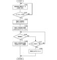
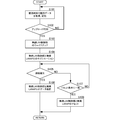
- Block diagram of an observation system according to the first embodiment of the present invention Flowchart of wireless LANAP reset control according to the first embodiment of the present invention Flowchart of reset control of wireless LANAP and wireless LAN control unit according to second embodiment of the present invention The block diagram of the observation system which concerns on the 3rd Embodiment of this invention.
- observation data relay device and the observation system according to the first embodiment of the present invention will be described with reference to the drawings.
- the observation system shown in the present embodiment is used in, for example, a landslide detection system.
- the configuration and method of the present embodiment can be applied to any system that transmits and receives observation data by wireless communication in a system that analyzes a predetermined phenomenon using observation data acquired at a remote location.
- FIG. 1 is a block diagram of an observation system according to the first embodiment of the present invention.
- the observation system 10 includes a slave unit (observation data transmission device) 20, a master unit (observation data relay device) 30, a file server 40, an analysis device 50, and a communication network 100.
- the slave 20 is placed at the observation position. When there are a plurality of observation positions, the slave unit 20 is arranged for each observation position.
- the slave unit 20 includes a control unit 21, a GNSS receiver 22, a GNSS antenna 23, a wireless LAN control unit 24, a wireless LAN antenna 25, a memory 26, and a notification unit 27.
- mobile_unit 20 is arrange
- the control unit 21 performs overall control of the slave unit 20.
- the control unit 21 temporarily stores the observation data, and uploads the stored observation data to the file server 40 via the parent device 30 and the communication network 100 at each upload time.
- the GNSS receiver 22 is connected to the control unit 21.
- the GNSS receiver 22 generates observation data from the GNSS signal received by the GNSS antenna 23.
- the GNSS receiver 22 outputs the generated observation data to the control unit 21.
- GNSS is an abbreviation for Global Navigation Satelite System, and includes GPS (Global Positioning System), GLONASS (Global Navigation Satelite System), Galileo, and the like.
- interval for generating observation data is shorter than the interval of upload time executed by the control unit 21.
- the observation time interval is 1 second
- the upload time interval is 5 minutes.
- the observation data generated by the GNSS receiver 22 is data used for analysis and detection of landslide such as carrier phase.
- the observation data is data obtained from the reception result (data obtained by acquisition and tracking) of the GNSS signal.
- the GNSS receiver 22 demodulates the navigation message from the GNSS signal.
- the GNSS receiver 22 acquires time data from the navigation message.
- the GNSS receiver 22 may measure the slave unit 20 from the tracking result of the GNSS signal.
- the observation data includes a positioning result.
- the wireless LAN control unit 24 is connected to the wireless LAN antenna 25 and the control unit 21.
- the wireless LAN control unit 24 performs wireless communication with the wireless LAN AP 32 via the wireless LAN antenna 25 and the wireless LAN antenna 31 according to a predetermined protocol.
- the wireless LAN control unit 24 converts the observation data given from the control unit 21 into a wireless communication protocol and transmits it from the wireless LAN antenna 25. Further, the wireless LAN control unit 24 converts the remote setting data received from the base unit 30 received by the wireless LAN antenna 25 into a protocol and outputs it to the control unit 21.
- the memory 26 is connected to the control unit 21.
- the memory 26 temporarily stores observation data.
- the notification unit 27 is connected to the control unit 21.
- the notification unit 27 is configured by a simple display element such as an LED.
- the notification unit 27 is driven in a predetermined display mode by a notification signal from the control unit 21.
- Base unit 30 includes wireless LAN antennas 31 and 36, wireless LANAP (access point) 32, router 33, control unit 34, wireless LAN control unit 35, GNSS receiver 37, GNSS antenna 38, memory 39, and power supply 300. Is provided. Similarly to the slave unit 20, the master unit 30 is also arranged at the observation position, and is preferably arranged in an open sky environment as much as possible.
- the control unit 34, the wireless LAN control unit 35, the wireless LAN antenna 36, the GNSS receiver 37, the GNSS antenna 38, and the memory 39 are the control unit 21, the wireless LAN control unit 24, and the wireless LAN antenna 25 of the slave unit 20 described above.
- GNSS receiver 22, GNSS antenna 23, and memory 26 have the same functions.
- control unit 34 monitors the communication state between the wireless LAN control unit 35 and the wireless LAN AP 32.
- the control unit 34 performs reset control on the power supply 300 if the wireless communication needs to be reset. Specific contents of the reset control will be described later.
- the wireless LAN AP 32 performs wireless communication with the wireless LAN control unit 24 via the wireless LAN antenna 31 and the wireless LAN antenna 25 using a predetermined protocol.
- the wireless LAN AP 32 converts the observation data received from the slave unit 20 received by the wireless LAN antenna 31 into a protocol and outputs it to the router 33.
- the wireless LAN AP 32 performs wireless communication with the wireless LAN control unit 35 via the wireless LAN antenna 31 and the wireless LAN antenna 36 in the base unit 30 according to a predetermined protocol. Also, the wireless LAN AP 32 converts the observation data generated by the base unit 30 and received by the wireless LAN antenna 31 into a protocol and outputs it to the router 33.
- the wireless LAN AP 32 converts the remote setting data acquired via the router 33 into a protocol and transmits it from the wireless LAN antenna 31.
- the router 33 connects the wireless LAN AP 32 to the network 100. That is, the router 33 executes protocol conversion between the wireless communication network between the slave device 20 and the portion having the slave function in the master device 30 and the master device 30 and the network 100. The router 33 transmits the observation data output from the wireless LAN AP 32 to the file server 40. The router 33 outputs a setting signal from the analysis device 50 connected via the network 100 to the wireless LAN AP 32.
- the file server 40 stores observation data transmitted from the parent device 30. Further, the file server 40 transmits observation data to the analysis device 50 in response to a read request from the analysis device 50.
- the analysis device 50 generates detection data for the observation target using the observation data read from the file server 40. For example, if the observation system 10 is a landslide detection system, the position change and speed of each observation position are acquired from observation data, and a landslide is detected.
- the analysis device 50 transmits a setting signal to the parent device 30 and the child device 20.
- the setting signal is set by an operator using an operation input unit provided in the analysis device 50.
- the setting signal is set by the analysis device 50 based on the analysis results so far.
- FIG. 2 is a flowchart of wireless LANAP reset control according to the first embodiment of the present invention.
- the control unit 34 acquires the observation data at the observation time and stores it in the memory 39 (S101). The control unit 34 continues to acquire and store observation data until it is detected that the upload time has been reached (S102: NO).
- control unit 34 When the control unit 34 detects that the upload time has come (S102: YES), the control unit 34 wakes up the wireless LAN control unit 35 (S103). As a result, the power is supplied from the power source 300 to the wireless LAN control unit 35 and the wireless LAN control unit 35 is activated.
- the wireless LAN control unit 35 When the wireless LAN control unit 35 is activated, the wireless LAN control unit 35 performs negotiation regarding communication with the wireless LAN AP 32 (S104). The wireless LAN control unit 35 outputs the negotiation result to the control unit 34.
- the control unit 34 detects whether or not the wireless connection between the wireless LAN control unit 35 and the wireless LAN AP 32 is established from the result of the negotiation. If the wireless connection is established (S105: YES), the control unit 34 transmits the observation data through wireless communication between the wireless LAN control unit 35 and the wireless LAN AP 32 (S106).
- the control unit 34 detects whether or not the reset condition is met (S107).
- the reset condition is based on the number of negotiations and the elapsed time from the start of the negotiation. When the number of times is used as a reference, the reset condition is that the number of negotiation failures reaches the threshold number. When the elapsed time is used as a reference, the reset condition is that the elapsed time has reached the threshold time.
- the control unit 34 does not perform reset control during a period that does not match the reset condition (S107: NO). As a result, the wireless LAN control unit 35 continues negotiation regarding communication with the wireless LAN AP 32.
- control unit 34 When the control unit 34 detects that the reset condition is met (S107: YES), the control unit 34 performs reset control of the wireless LAN AP 32. Specifically, the power supply to the wireless LAN AP 32 is stopped.
- the master unit 30 since the master unit 30 has the function of the slave unit 20, the number of slave units prepared as the observation system 10 can be reduced by one. In particular, a landslide detection system always requires a slave unit at a position where it does not move. In addition, since the master unit has a relay function of observation data, it is preferable to arrange it at a position where it does not move. Therefore, by using the child device whose position does not move as the parent device, the child device and the parent device can be used more effectively and effectively.
- observation data relay device and an observation system according to the second embodiment will be described with reference to the drawings.
- the observation data relay device and the observation system according to this embodiment are different from the observation data relay device and the observation system according to the first embodiment only in reset control.
- FIG. 3 is a flowchart of reset control of the wireless LANAP and the wireless LAN control unit according to the second embodiment of the present invention. As shown in FIG. 3, since only the reset control is different in the observation data relay device and the observation system of this embodiment, only different points will be described.
- control unit 34 When the control unit 34 detects that the reset condition is met (S107: YES), the control unit 34 performs reset control of the wireless LAN AP 32 and the wireless LAN control unit 35. Specifically, power supply to the wireless LAN AP 32 and the wireless LAN control unit 35 is stopped.
- wireless communication with the wireless LAN AP 32 and the wireless LAN control unit 35 is caused not by the wireless LAN AP 32 but by the wireless LAN control unit 35. Can be restored. Thereby, the return
- FIG. 4 is a block diagram of an observation system according to the third embodiment of the present invention.
- the observation data relay device 30A according to this embodiment is obtained by omitting the GNSS receiver 37 and the GNSS antenna 38 from the observation data relay device 30 according to the first embodiment.
- the same effects as those of the first embodiment can be obtained. Furthermore, the number of components of the observation data relay device 30A of this embodiment can be reduced. As a result, the observation data relay device 30A can be configured to be small and inexpensive.
- the memory 39 can be further omitted.
- the power supply to the wireless LAN AP 32 or the wireless LAN control unit 35 is stopped as the reset control.
- the control unit 34 may generate a reset signal and force the wireless LAN AP 32 or the wireless LAN control unit 35 to restart by the reset signal.
- Observation system 20 Slave unit (observation data transmitter) 21: Control unit 22: GNSS receiver 23: GNSS antenna 24: Wireless LAN control unit 25: Wireless LAN antenna 26: Memory 27: Notification unit 30, 30A: Master unit (observation data relay device) 31, 36: Wireless LAN antenna 32: Wireless LANAP 33: Router 34: Control unit 35: Wireless LAN control unit 37: GNSS receiver 38: GNSS antenna 39: Memory 40: File server 50: Analysis device 100: Communication network 300: Power supply
Landscapes
- Engineering & Computer Science (AREA)
- Computer Networks & Wireless Communication (AREA)
- Signal Processing (AREA)
- Physics & Mathematics (AREA)
- Electromagnetism (AREA)
- Mobile Radio Communication Systems (AREA)
Abstract
【課題】観測データ中継装置の通信の不具合を自動で検出して、無線通信を復帰する。 【解決手段】親機(観測データ中継装置)30は、無線LANAP32、ルータ33、制御部34、および、無線LAN制御部35を備える。無線LANAP32は、外部から観測データを受信する。ルータ33は、観測データをネットワークに接続された機器に送信する。無線LAN制御部35は、無線LANAP32との間で無線通信を行う制御部34は、無線LANAP32と無線LAN制御部35との無線通信が確立していないことを検出すると、無線LANAP32のリセット制御を行う。
Description
本発明は、地滑り等の物理的な変化を観測する観測データを中継する観測データ中継装置、この観測データ中継装置を含む観測システムに関する。
現在、防災の観点から、地滑り等の観測を行うシステムが各種考案されている。例えば、特許文献1に記載の観測データ回収システムは、複数の解析装置、複数の中継装置、および集約装置を備える。
1つの中継装置には複数の解析装置がリンクしている。各中継装置がリンクする解析装置は異なる。集約装置は、複数の中継装置にリンクしている。
中継装置は、自身がリンクしている複数の解析装置の観測データを取得する。中継装置は、取得した複数の観測データをまとめて、集約装置に送信する。
このように、従来の観測データ回収システムでは、観測データを取得する解析装置は、中継機を介して、集約装置に観測データを送信している。
上述の従来の観測データ回収システムでは、中継機と集約装置との間のデータ通信が確立されていても、観測データを集約装置に送ることができないことがある。このような問題は、中継機の通信機能の不具合によって生じることが多い。
しかしながら、従来の観測データ回収システムでは、このような不具合が生じても、中継機自身がこの不具合を検知することができない。そして、中継機の不具合が生じている期間は、観測データを集約装置に送信することができず、観測データの欠損を生じてしまう。
本発明の目的は、無線通信の不具合を自動検出して、通信を復帰させることである。
この発明の観測データ中継装置は、外部から観測データを受信する無線LANアクセスポイント、観測データをネットワークに接続された機器に送信するルータ、無線LANアクセスポイントとの間で無線通信を行う無線LAN制御部、および、制御部を備える。制御部は、無線LANアクセスポイントと無線LAN制御部との無線通信が確立していないことを検出すると、無線LANアクセスポイントのリセット制御を行う。
この構成では、無線LANアクセスポイントの不具合を、無線LANアクセスポイントを備える観測データ中継装置自身で検出して、リセットすることができる。
また、この発明の観測データ中継装置は、無線LAN制御部および無線LANアクセスポイントに電源を供給するAP用電源を備える。制御部は、リセット制御として、AP用電源から無線LANアクセスポイントへの電力供給を一時的に停止する。
この構成では、無線LANアクセスポイントへの電力供給が切れることで、無線LANアクセスポイントのリセットを確実に行うことができる。
また、この発明の観測データ中継装置は、GNSS信号を受信して観測データを生成するGNSS受信機を、さらに備える。
この構成では、観測データ中継装置で、観測データを生成することができる。
また、この発明の観測データ中継装置では、制御部は、無線LANアクセスポイントと無線LAN制御部との無線通信が確立していないことを検出すると、無線LAN制御部のリセット制御を行う。
この構成では、無線通信が確立していない原因が無線LAN制御部であっても、無線通信をリセットすることができる。
また、この発明の観測システムは、上述のいずれかに記載の観測データ中継装置、観測データ送信装置、および、ファイルサーバを備える。観測データ送信装置は、GNSS信号を受信して観測データを生成し、観測データ中継装置に無線通信によって送信する。ファイルサーバは、観測データ送信装置にネットワークを介して接続し、観測データを保存する。
この構成では、観測データ中継装置の不具合を観測データ中継装置自身で検出して復帰する観測システムを実現できる。これにより、ファイルサーバに保存されるべき観測データの欠損を抑制することできる。また、観測データ中継装置に観測データの生成機能を持たせることによって、ファイルサーバに保存する観測データ数を減らすことなく、単体の観測データ送信装置の個数を減らすことができる。
この発明によれば、観測データ中継装置が自身の通信の不具合を自動で検出して、通信を復帰させることができる。
本発明の第1の実施形態に係る観測データ中継装置、観測システムについて、図を参照して説明する。なお、本実施形態で示す観測システムは、例えば、地滑り検出システム等に用いられる。しかしながら、遠隔地で取得した観測データを用いて、所定の現象について解析を行うシステムにおいて、観測データを無線通信で送受信するシステムであれば、本実施形態の構成および方法を適用することができる。
図1は、本発明の第1の実施形態に係る観測システムのブロック図である。観測システム10は、子機(観測データ送信装置)20、親機(観測データ中継装置)30、ファイルサーバ40、解析装置50、および通信ネットワーク100を備える。
子機20は、観測位置に配置される。観測位置が複数箇所の場合、観測位置毎に子機20が配置される。
子機20は、制御部21、GNSS受信機22、GNSSアンテナ23、無線LAN制御部24、無線LAN用アンテナ25、メモリ26、および、通知部27を備える。子機20は、観測対象位置に配置されている。子機20は、可能な限りオープンスカイな環境に配置されていることが好ましい。
制御部21は、子機20の全体制御を行う。また、制御部21は、観測データを一時記憶し、アップロード時刻毎に、記憶していた観測データを、親機30、通信ネットワーク100を介して、ファイルサーバ40にアップロードする。
GNSS受信機22は、制御部21に接続されている。GNSS受信機22は、GNSSアンテナ23で受信したGNSS信号から観測データを生成する。GNSS受信機22は、生成した観測データを制御部21に出力する。
GNSSとは、Global Navigation Satellite Systemの略語であり、GPS(Global Positioning System)、GLONASS(Global Navigation Satellite System)、Galileo等を含む。
なお、観測データを生成する間隔(観測時刻の間隔)は、制御部21が実行するアップロード時刻の間隔よりも短い。例えば、観測時刻の間隔は、1秒であり、アップロード時刻の間隔は5分である。これらの間隔は、解析装置50等によって変更可能である。
GNSS受信機22で生成される観測データは、搬送波位相等、地滑りの解析、検出に利用されるデータである。観測データは、GNSS信号の受信結果(捕捉、追尾によって得られるデータ)から得られるデータである。
また、GNSS受信機22は、GNSS信号から航法メッセージを復調する。GNSS受信機22は、航法メッセージから時刻データを取得する。なお、GNSS受信機22は、GNSS信号の追尾結果から子機20を測位してもよい。この場合、観測データには、測位結果が含まれる。
無線LAN制御部24は、無線LAN用アンテナ25、制御部21に接続されている。無線LAN制御部24は、無線LAN用アンテナ25および無線LAN用アンテナ31を介した無線LAN用AP32との無線通信を、予め決められたプロトコルによって実行する。無線LAN制御部24は、制御部21から与えられた観測データを、無線通信のプロトコルに変換して、無線LAN用アンテナ25から送信する。また、無線LAN制御部24は、無線LAN用アンテナ25で受信した親機30からの遠隔設定データをプロトコル変換して制御部21に出力する。
メモリ26は、制御部21に接続されている。メモリ26は観測データを一時記憶する。
通知部27は、制御部21に接続されている。通知部27は、LED等の簡易な表示素子によって構成されている。通知部27は、制御部21からの通知信号によって、所定の表示態様に駆動される。
親機30は、無線LAN用アンテナ31,36、無線LANAP(アクセスポイント)32、ルータ33、制御部34、無線LAN制御部35、GNSS受信機37、GNSSアンテナ38、メモリ39、および、電源300を備える。親機30も、子機20と同様に、観測位置に配置されており、可能な限りオープンスカイな環境に配置されていることが好ましい。
制御部34、無線LAN制御部35、無線LAN用アンテナ36、GNSS受信機37、GNSSアンテナ38、メモリ39は、上述の子機20の制御部21、無線LAN制御部24、無線LAN用アンテナ25、GNSS受信機22、GNSSアンテナ23、メモリ26と同じ機能を有する。
さらに、制御部34は、無線LAN制御部35と無線LANAP32との通信状態を監視する。制御部34は、無線通信にリセットが必要な状態であれば、電源300に対するリセット制御を行う。リセット制御の具体的な内容は、後述する。
無線LANAP32は、無線LAN用アンテナ31および無線LAN用アンテナ25を介した無線LAN制御部24との無線通信を、予め決められたプロトコルによって実行する。また、無線LANAP32は、無線LAN用アンテナ31で受信した子機20からの観測データをプロトコル変換してルータ33に出力する。
無線LANAP32は、親機30内において、無線LAN用アンテナ31および無線LAN用アンテナ36を介した無線LAN制御部35との無線通信を、予め決められたプロトコルによって実行する。また、無線LANAP32は、親機30で生成され、無線LAN用アンテナ31で受信した観測データをプロトコル変換してルータ33に出力する。
無線LANAP32は、ルータ33を介して取得した遠隔設定データをプロトコル変換して、無線LAN用アンテナ31から送信する。
ルータ33は、無線LANAP32をネットワーク100に接続する。すなわち、ルータ33は、子機20および親機30内の子機の機能を有する部分と親機30との無線通信網とネットワーク100との間でのプロトコル変換を実行する。ルータ33は、無線LANAP32から出力される観測データを、ファイルサーバ40に送信する。ルータ33は、ネットワーク100を介して接続された解析装置50からの設定信号を、無線LANAP32に出力する。
ファイルサーバ40は、親機30から送信される観測データを記憶する。また、ファイルサーバ40は、解析装置50からの読み出し要求に応じて、観測データを、解析装置50に送信する。
解析装置50は、ファイルサーバ40から読み出した観測データを用いて、観測対象に対する検出データを生成する。例えば、観測システム10が地滑り検出システムであれば、観測データから各観測位置の位置変化および速度を取得して、地滑りを検出する。解析装置50は、親機30および子機20に対して設定信号を送信する。設定信号は、解析装置50に備えられた操作入力部を用いてオペレータによって設定される。また、設定信号は、解析装置50がこれまでの解析結果に基づいて設定される。
このような構成からなる観測システムにおいて、親機(観測データ中継装置)30は、次に示す方法によって、無線LANAP32のリセット制御を行う。図2は、本発明の第1の実施形態に係る無線LANAPのリセット制御のフローチャートである。
制御部34は、観測時刻になると観測データを取得し、メモリ39に記憶する(S101)。制御部34は、アップロード時刻に達したことを検出するまで(S102:NO)、観測データの取得、記憶を継続する。
制御部34は、アップロード時刻になったことを検出すると(S102:YES)、無線LAN制御部35をウェイクアップ制御する(S103)。これにより、無線LAN制御部35に電源300が電力が供給され、無線LAN制御部35が起動する。
無線LAN制御部35は、起動すると、無線LANAP32との通信に関するネゴシエーションを実行する(S104)。無線LAN制御部35は、ネゴシエーションの結果を制御部34に出力する。
制御部34は、ネゴシエーションの結果から、無線LAN制御部35と無線LANAP32との無線接続が確立されているか否かを検出する。制御部34は、無線接続が確立されていれば(S105:YES)、無線LAN制御部35と無線LANAP32との無線通信によって、観測データを送信する(S106)。
制御部34は、無線接続が確立されていなければ(S105:NO)、リセット条件に一致するか否かを検出する(S107)。リセット条件とは、ネゴシエーションの回数、ネゴシエーションを開始してからの経過時間を基準としている。回数を基準とする場合、ネゴシエーションの失敗回数が閾値回数に達したことがリセット条件となる。経過時間を基準とする場合、経過時間が閾値時間に達したことがリセット条件となる。
制御部34は、リセット条件に一致しない期間は(S107:NO)、リセット制御を行わない。これにより、無線LAN制御部35は、無線LANAP32との通信に関するネゴシエーションを継続する。
制御部34は、リセット条件に一致したことを検出すると(S107:YES)、無線LANAP32のリセット制御を行う。具体的には、無線LANAP32に対する電源供給を停止する。
このように、本実施形態の構成を用いることによって、親機30の無線LANAP32の不具合による無線通信障害が生じても、これを確実に検出することができる。さらに、親機30の無線LANAP32による無線通信障害を、自動的に復帰することができる。
さらに、本実施形態の構成では、親機30に子機20の機能を備えているので、観測システム10としての用意する子機単体の個数を一つ減らすことができる。特に、地滑り検出システムでは、動かない位置に子機を必ず必要とする。また、親機は観測データの中継機能を有するため、動かない位置に配置することが好ましい。したがって、この位置が動かない子機を親機に兼用させることによって、より効果的且つ有効に子機および親機を利用することができる。
次に、第2の実施形態に係る観測データ中継装置、観測システムについて、図を参照して説明する。本実施形態に係る観測データ中継装置、および観測システムは、リセット制御のみが、第1の実施形態に係る観測データ中継装置、および観測システムと異なる。
図3は、本発明の第2の実施形態に係る無線LANAPおよび無線LAN制御部のリセット制御のフローチャートである。図3に示すように、本実施形態の観測データ中継装置、観測システムでは、リセット制御のみが異なるので、異なる箇所のみを説明する。
制御部34は、リセット条件に一致したことを検出すると(S107:YES)、無線LANAP32および無線LAN制御部35のリセット制御を行う。具体的には、無線LANAP32および無線LAN制御部35に対する電源供給を停止する。
このような制御を行うことによって、無線LANAP32および無線LAN制御部35との無線通信の不具合が、無線LANAP32に起因するものでなく、無線LAN制御部35に起因するものであっても、無線通信を復帰できる。これにより、無線通信の復帰をより確実実行することができる。
次に、第3の実施形態に係る観測データ中継装置、観測システムについて、図を参照して説明する。本実施形態に係る観測データ中継装置、および観測システムは、観測データ中継装置の構成が第1の実施形態と異なる。図4は、本発明の第3の実施形態に係る観測システムのブロック図である。
本実施形態に係る観測データ中継装置30Aは、第1の実施形態に係る観測データ中継装置30に対して、GNSS受信機37、および、GNSSアンテナ38を省略したものである。
このような構成であっても、第1の実施形態と同様の作用効果を得ることができる。さらに、本実施形態の観測データ中継装置30Aの構成要素を少なくできる。これにより、観測データ中継装置30Aを小型、安価に構成することができる。なお、メモリ39をさらに省略することもできる。
なお、上述の説明では、リセット制御として、無線LANAP32或いは無線LAN制御部35に対する電源供給を停止する態様を示した。しかしながら、リセット制御として他の態様を用いることも可能である。例えば、制御部34は、リセット信号を生成し、当該リセット信号によって、無線LANAP32或いは無線LAN制御部35に対して、再起動を強制的に行わせてもよい。
10:観測システム
20:子機(観測データ送信装置)
21:制御部
22:GNSS受信機
23:GNSSアンテナ
24:無線LAN制御部
25:無線LAN用アンテナ
26:メモリ
27:通知部
30,30A:親機(観測データ中継装置)
31,36:無線LAN用アンテナ
32:無線LANAP
33:ルータ
34:制御部
35:無線LAN制御部
37:GNSS受信機
38:GNSSアンテナ
39:メモリ
40:ファイルサーバ
50:解析装置
100:通信ネットワーク
300:電源
20:子機(観測データ送信装置)
21:制御部
22:GNSS受信機
23:GNSSアンテナ
24:無線LAN制御部
25:無線LAN用アンテナ
26:メモリ
27:通知部
30,30A:親機(観測データ中継装置)
31,36:無線LAN用アンテナ
32:無線LANAP
33:ルータ
34:制御部
35:無線LAN制御部
37:GNSS受信機
38:GNSSアンテナ
39:メモリ
40:ファイルサーバ
50:解析装置
100:通信ネットワーク
300:電源
Claims (5)
- 外部から観測データを受信する無線LANアクセスポイントと、
前記観測データをネットワークに接続された機器に送信するルータと、
前記無線LANアクセスポイントとの間で無線通信を行う無線LAN制御部と、
前記無線LANアクセスポイントと前記無線LAN制御部との無線通信が確立していないことを検出すると、前記無線LANアクセスポイントのリセット制御を行う制御部と、
を備える観測データ中継装置。 - 請求項1に記載の観測データ中継装置であって、
前記無線LAN制御部および前記無線LANアクセスポイントに電源を供給するAP用電源を備え、
前記制御部は、リセット制御として、前記AP用電源から前記無線LANアクセスポイントへの電力供給を一時的に停止する、
観測データ中継装置。 - 請求項2に記載の観測データ中継装置であって、
前記制御部は、前記無線通信が確立していないことを検出すると、前記無線LAN制御部のリセット制御を行う、
観測データ中継装置。 - 請求項1乃至請求項3のいずれかに記載の観測データ中継装置であって、
GNSS信号を受信して観測データを生成するGNSS受信機を、さらに備える、
観測データ中継装置。 - 請求項1乃至請求項4のいずれかに記載の観測データ中継装置と、
GNSS信号を受信して前記観測データを生成し、前記観測データ中継装置に無線通信によって送信する観測データ送信装置と、
前記観測データ送信装置に前記ネットワークを介して接続し、前記観測データが保存されるファイルサーバと、
を備えた観測システム。
Priority Applications (1)
| Application Number | Priority Date | Filing Date | Title |
|---|---|---|---|
| JP2017507559A JP6511131B2 (ja) | 2015-03-24 | 2016-02-03 | 観測データ中継装置、観測システム |
Applications Claiming Priority (2)
| Application Number | Priority Date | Filing Date | Title |
|---|---|---|---|
| JP2015-061051 | 2015-03-24 | ||
| JP2015061051 | 2015-03-24 |
Publications (1)
| Publication Number | Publication Date |
|---|---|
| WO2016152263A1 true WO2016152263A1 (ja) | 2016-09-29 |
Family
ID=56977300
Family Applications (1)
| Application Number | Title | Priority Date | Filing Date |
|---|---|---|---|
| PCT/JP2016/053191 Ceased WO2016152263A1 (ja) | 2015-03-24 | 2016-02-03 | 観測データ中継装置、観測システム |
Country Status (2)
| Country | Link |
|---|---|
| JP (1) | JP6511131B2 (ja) |
| WO (1) | WO2016152263A1 (ja) |
Cited By (1)
| Publication number | Priority date | Publication date | Assignee | Title |
|---|---|---|---|---|
| CN110446245A (zh) * | 2019-06-20 | 2019-11-12 | 广州南方卫星导航仪器有限公司 | 一种原始观测数据的传输方法、终端设备、存储介质 |
Citations (4)
| Publication number | Priority date | Publication date | Assignee | Title |
|---|---|---|---|---|
| JP2004185459A (ja) * | 2002-12-05 | 2004-07-02 | Furuno Electric Co Ltd | 観測データ回収システムおよび観測データの回収方法 |
| JP2005033631A (ja) * | 2003-07-09 | 2005-02-03 | Nec Saitama Ltd | 基地局装置及び基地局装置の自己復帰方法 |
| JP2009248711A (ja) * | 2008-04-04 | 2009-10-29 | Denso Corp | 車載通信システム |
| JP2013110605A (ja) * | 2011-11-21 | 2013-06-06 | Hitachi Ltd | 無線基地局、及び、無線基地局の障害を検出するシステム |
-
2016
- 2016-02-03 JP JP2017507559A patent/JP6511131B2/ja active Active
- 2016-02-03 WO PCT/JP2016/053191 patent/WO2016152263A1/ja not_active Ceased
Patent Citations (4)
| Publication number | Priority date | Publication date | Assignee | Title |
|---|---|---|---|---|
| JP2004185459A (ja) * | 2002-12-05 | 2004-07-02 | Furuno Electric Co Ltd | 観測データ回収システムおよび観測データの回収方法 |
| JP2005033631A (ja) * | 2003-07-09 | 2005-02-03 | Nec Saitama Ltd | 基地局装置及び基地局装置の自己復帰方法 |
| JP2009248711A (ja) * | 2008-04-04 | 2009-10-29 | Denso Corp | 車載通信システム |
| JP2013110605A (ja) * | 2011-11-21 | 2013-06-06 | Hitachi Ltd | 無線基地局、及び、無線基地局の障害を検出するシステム |
Cited By (1)
| Publication number | Priority date | Publication date | Assignee | Title |
|---|---|---|---|---|
| CN110446245A (zh) * | 2019-06-20 | 2019-11-12 | 广州南方卫星导航仪器有限公司 | 一种原始观测数据的传输方法、终端设备、存储介质 |
Also Published As
| Publication number | Publication date |
|---|---|
| JP6511131B2 (ja) | 2019-05-15 |
| JPWO2016152263A1 (ja) | 2017-12-21 |
Similar Documents
| Publication | Publication Date | Title |
|---|---|---|
| JP6183016B2 (ja) | センサ情報処理装置、センサ情報処理方法およびセンサ情報処理プログラム | |
| RU2014124988A (ru) | Беспроводной релейный модуль с функцией аварийного вызова | |
| JP2008306472A5 (ja) | ||
| KR20170118734A (ko) | 레인징 프로토콜을 위한 방법들 및 시스템들 | |
| JP2016102789A (ja) | 変位監視システム及び変位監視方法 | |
| JP2012239137A (ja) | 無線管理システム、無線端末装置および伝送管理方法 | |
| JP6511131B2 (ja) | 観測データ中継装置、観測システム | |
| JP2007327749A (ja) | リアルタイムキネマティックgpsシステム | |
| TW200949282A (en) | Controlling satellite navigation receivers in response to low frequency electromagnetic signals | |
| JP6412326B2 (ja) | 無線式警報システム | |
| JP6554295B2 (ja) | 観測データ送信装置、観測システム、および、観測データ送信方法 | |
| CA2992946C (en) | Satellite modem location tracking | |
| EP2889578A1 (en) | Indoor system for providing navigation data | |
| JP2007312165A (ja) | 位置情報通信端末装置 | |
| JP2016169967A (ja) | 移動体用監視システム、子機、親機、及びプログラム | |
| KR101502400B1 (ko) | 다중 주파수 대역 기반의 의사위성 항법시스템 | |
| JP2001358633A (ja) | 衛星運用システム | |
| US20150271817A1 (en) | Communication device, wireless communication system, communication method, and computer program product | |
| JP4648735B2 (ja) | デジタル無線システム | |
| US10235067B2 (en) | Time shift retransmission systems | |
| JP6637661B2 (ja) | 移動体用監視システム、子機、親機、及びプログラム | |
| KR102331536B1 (ko) | 네트워크 장치 및 그 동작 방법 | |
| JP2011182346A (ja) | 無線テレメータシステム | |
| JP2012165116A (ja) | 通信システム | |
| JP2017175486A (ja) | 位置情報通知機能を有する無線子機 |
Legal Events
| Date | Code | Title | Description |
|---|---|---|---|
| 121 | Ep: the epo has been informed by wipo that ep was designated in this application |
Ref document number: 16768166 Country of ref document: EP Kind code of ref document: A1 |
|
| ENP | Entry into the national phase |
Ref document number: 2017507559 Country of ref document: JP Kind code of ref document: A |
|
| NENP | Non-entry into the national phase |
Ref country code: DE |
|
| 122 | Ep: pct application non-entry in european phase |
Ref document number: 16768166 Country of ref document: EP Kind code of ref document: A1 |