WO2016151893A1 - Endoscope system - Google Patents
Endoscope system Download PDFInfo
- Publication number
- WO2016151893A1 WO2016151893A1 PCT/JP2015/076516 JP2015076516W WO2016151893A1 WO 2016151893 A1 WO2016151893 A1 WO 2016151893A1 JP 2015076516 W JP2015076516 W JP 2015076516W WO 2016151893 A1 WO2016151893 A1 WO 2016151893A1
- Authority
- WO
- WIPO (PCT)
- Prior art keywords
- signal
- unit
- test pattern
- test
- pattern signal
- Prior art date
Links
Images


Classifications
-
- A—HUMAN NECESSITIES
- A61—MEDICAL OR VETERINARY SCIENCE; HYGIENE
- A61B—DIAGNOSIS; SURGERY; IDENTIFICATION
- A61B1/00—Instruments for performing medical examinations of the interior of cavities or tubes of the body by visual or photographical inspection, e.g. endoscopes; Illuminating arrangements therefor
- A61B1/04—Instruments for performing medical examinations of the interior of cavities or tubes of the body by visual or photographical inspection, e.g. endoscopes; Illuminating arrangements therefor combined with photographic or television appliances
-
- G—PHYSICS
- G02—OPTICS
- G02B—OPTICAL ELEMENTS, SYSTEMS OR APPARATUS
- G02B23/00—Telescopes, e.g. binoculars; Periscopes; Instruments for viewing the inside of hollow bodies; Viewfinders; Optical aiming or sighting devices
- G02B23/24—Instruments or systems for viewing the inside of hollow bodies, e.g. fibrescopes
- G02B23/2476—Non-optical details, e.g. housings, mountings, supports
- G02B23/2484—Arrangements in relation to a camera or imaging device
-
- A—HUMAN NECESSITIES
- A61—MEDICAL OR VETERINARY SCIENCE; HYGIENE
- A61B—DIAGNOSIS; SURGERY; IDENTIFICATION
- A61B1/00—Instruments for performing medical examinations of the interior of cavities or tubes of the body by visual or photographical inspection, e.g. endoscopes; Illuminating arrangements therefor
- A61B1/00002—Operational features of endoscopes
- A61B1/00004—Operational features of endoscopes characterised by electronic signal processing
- A61B1/00009—Operational features of endoscopes characterised by electronic signal processing of image signals during a use of endoscope
-
- A—HUMAN NECESSITIES
- A61—MEDICAL OR VETERINARY SCIENCE; HYGIENE
- A61B—DIAGNOSIS; SURGERY; IDENTIFICATION
- A61B1/00—Instruments for performing medical examinations of the interior of cavities or tubes of the body by visual or photographical inspection, e.g. endoscopes; Illuminating arrangements therefor
- A61B1/00002—Operational features of endoscopes
- A61B1/00043—Operational features of endoscopes provided with output arrangements
- A61B1/00045—Display arrangement
-
- A—HUMAN NECESSITIES
- A61—MEDICAL OR VETERINARY SCIENCE; HYGIENE
- A61B—DIAGNOSIS; SURGERY; IDENTIFICATION
- A61B1/00—Instruments for performing medical examinations of the interior of cavities or tubes of the body by visual or photographical inspection, e.g. endoscopes; Illuminating arrangements therefor
- A61B1/00002—Operational features of endoscopes
- A61B1/00057—Operational features of endoscopes provided with means for testing or calibration
-
- A—HUMAN NECESSITIES
- A61—MEDICAL OR VETERINARY SCIENCE; HYGIENE
- A61B—DIAGNOSIS; SURGERY; IDENTIFICATION
- A61B1/00—Instruments for performing medical examinations of the interior of cavities or tubes of the body by visual or photographical inspection, e.g. endoscopes; Illuminating arrangements therefor
- A61B1/00112—Connection or coupling means
- A61B1/00114—Electrical cables in or with an endoscope
-
- A—HUMAN NECESSITIES
- A61—MEDICAL OR VETERINARY SCIENCE; HYGIENE
- A61B—DIAGNOSIS; SURGERY; IDENTIFICATION
- A61B1/00—Instruments for performing medical examinations of the interior of cavities or tubes of the body by visual or photographical inspection, e.g. endoscopes; Illuminating arrangements therefor
- A61B1/00112—Connection or coupling means
- A61B1/00121—Connectors, fasteners and adapters, e.g. on the endoscope handle
-
- A—HUMAN NECESSITIES
- A61—MEDICAL OR VETERINARY SCIENCE; HYGIENE
- A61B—DIAGNOSIS; SURGERY; IDENTIFICATION
- A61B1/00—Instruments for performing medical examinations of the interior of cavities or tubes of the body by visual or photographical inspection, e.g. endoscopes; Illuminating arrangements therefor
- A61B1/04—Instruments for performing medical examinations of the interior of cavities or tubes of the body by visual or photographical inspection, e.g. endoscopes; Illuminating arrangements therefor combined with photographic or television appliances
- A61B1/045—Control thereof
-
- G—PHYSICS
- G02—OPTICS
- G02B—OPTICAL ELEMENTS, SYSTEMS OR APPARATUS
- G02B23/00—Telescopes, e.g. binoculars; Periscopes; Instruments for viewing the inside of hollow bodies; Viewfinders; Optical aiming or sighting devices
- G02B23/24—Instruments or systems for viewing the inside of hollow bodies, e.g. fibrescopes
-
- H—ELECTRICITY
- H04—ELECTRIC COMMUNICATION TECHNIQUE
- H04N—PICTORIAL COMMUNICATION, e.g. TELEVISION
- H04N17/00—Diagnosis, testing or measuring for television systems or their details
- H04N17/002—Diagnosis, testing or measuring for television systems or their details for television cameras
-
- H—ELECTRICITY
- H04—ELECTRIC COMMUNICATION TECHNIQUE
- H04N—PICTORIAL COMMUNICATION, e.g. TELEVISION
- H04N23/00—Cameras or camera modules comprising electronic image sensors; Control thereof
- H04N23/50—Constructional details
- H04N23/555—Constructional details for picking-up images in sites, inaccessible due to their dimensions or hazardous conditions, e.g. endoscopes or borescopes
Definitions
- the present invention relates to an endoscope system, and particularly to an endoscope system capable of performing a bit error rate test.
- an endoscope system including an endoscope for observing a region to be examined and performing various treatments by inserting an elongated endoscope into a body cavity or the like has been widely used.
- an endoscope system for example, in Japanese Patent Application Laid-Open No. 2002-199291, an endoscope in which a head-separated camera device (camera head) having a solid-state imaging device is attached to an eyepiece portion of an endoscope.
- a system is disclosed.
- This camera head has a built-in solid-state image sensor and is connected to an eyepiece of an endoscope, an electric cable extending from the head, and a connector provided at a base end of the electric cable. And is detachably connected to the camera control unit or the video processor via this connector portion.
- An imaging signal from a solid-state imaging device built in the camera head is input to the camera control unit. Then, the camera control unit performs predetermined image processing on the input imaging signal and outputs it to a connected monitor, thereby displaying an endoscopic image on the monitor.
- the camera control unit performs image processing such as video signal enlargement / reduction processing and area extraction so as to match the image pickup signal from the camera head with the performance of the connected monitor, and outputs it to the monitor.
- an object of the present invention is to provide an endoscope system that can reliably determine where an error has occurred when a transmission error occurs.
- An endoscope system includes a head-separated camera device having a head unit having an image sensor, a connector unit integrally connected to the head unit via a cable, and the connector unit.
- An endoscope system including the head-separated camera device and a detachable signal processing device, wherein the head unit includes a first test pattern generation unit that generates a first test pattern signal; A first transmission unit that transmits the first test pattern signal generated by the first test pattern generation unit via the cable, and the connector unit transmits from the first transmission unit.
- a first receiving unit for receiving the first test pattern signal, and a predetermined data pattern detected from the first test pattern signal received by the first receiving unit;
- a first detection circuit that outputs a generation start signal, and a second test pattern generation that generates a second test pattern signal that is the same pattern signal as the first test pattern based on the first generation start signal ,
- a first comparison circuit that outputs a comparison result comparing the first test pattern signal and the second test pattern signal, and a third test pattern generation unit that generates a third test pattern signal
- a second transmission unit that transmits the third test pattern signal generated by the third test pattern generation unit, and the signal processing device is transmitted from the second transmission unit.
- a second receiving unit that receives the third test pattern signal; and a second data generation unit that detects a predetermined data pattern from the third test pattern signal received by the second receiving unit and starts the second generation.
- a second detection circuit that outputs a signal
- a fourth test pattern generation unit that generates a fourth test pattern signal that is the same pattern signal as the third test pattern based on the second generation start signal
- a second comparison circuit for outputting a comparison result obtained by comparing the third test pattern signal and the fourth test pattern signal.
- the connector unit has a control signal generation circuit that instructs the head unit to transmit a test pattern signal.
- the head unit includes a selection circuit that switches a transmission signal between a video signal and a test pattern signal based on the control signal.
- FIG. It is a figure showing composition of an endoscope system concerning a 1st embodiment. It is a figure which shows the detailed circuit structure of the camera head and camera control unit of the endoscope system which concerns on 1st Embodiment.
- 3 is a diagram for explaining a detailed circuit configuration of a compare unit 21.
- FIG. It is a figure for demonstrating the example of the start operation
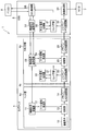
- FIG. 1 is a diagram illustrating a configuration of an endoscope system according to the first embodiment
- FIG. 2 is a detailed circuit configuration of a camera head and a camera control unit of the endoscope system according to the first embodiment.
- an endoscope system 1 includes, for example, an optical endoscope 2, a camera head 4 detachably connected to an eyepiece 3 of the endoscope 2, and a camera head 4.
- a camera control unit (hereinafter referred to as CCU) 5 that is detachably connected, a light source device 6 that supplies illumination light to the endoscope 2, and a video signal generated by an image processing unit (to be described later) of the CCU 5 are input.
- the personal computer 8 has a display unit 8a for displaying the result of the comparison test, and a keyboard 8b and a mouse 8c for instructing the start of the comparison test.
- the personal computer 8 has a recording unit (not shown) for recording the result of the compare test.
- a camera head 4 as a head-separated camera device includes a head part 4a connected to the eyepiece part 3, a cable 4b extending from the head part 4a, and a connector part 4c provided at the base end part of the cable 4b. Have The camera head 4 is connected to the CCU 5 via this connector portion 4c.
- the endoscope 2 is described as being connected to the camera head 4, for example, other camera heads having different specifications such as an enlargement ratio can also be connected.
- the CCU 5 can also be connected to a surgical instrument that is a medical device.
- the head unit 4 a includes an imaging device 10 configured by a CMOS sensor, a control signal receiving unit 11, a test signal generating unit 12, a switching unit 13, and a parasiri / LVDS transmitting unit 14. It is configured.
- the image sensor 10 is not limited to a CMOS sensor, and may be a CCD sensor or the like.
- the connector unit 4c includes a serial / LVDS receiver 20, a compare unit 21, a test signal generator 22, a control signal transmitter / receiver 23, a test signal generator 24, a switching unit 25, and a parallel / LVDS transmission. Part 26.
- the CCU 5 includes a serial / LVDS receiving unit 30, a comparing unit 31, a test signal generating unit 32, a control signal transmitting / receiving unit 33, an image processing unit 34, and a CCU control unit 35. Yes.
- the illumination light from the light source device 6 is transmitted to the endoscope 2 through a light guide (not shown), and is irradiated onto the subject from the distal end surface of the insertion unit through a light guide (not shown) in the insertion unit.
- Return light from the subject is imaged by the image sensor 10 of the head unit 4a.
- An imaging signal imaged by the imaging element 10 is output to the switching unit 13.
- the switching unit 13 outputs an imaging signal from the imaging device 10 to the parallel / LVDS transmission unit 14 of the connector unit 4c during normal endoscope observation. Note that the switching unit 13 outputs the test signal generated by the test signal generation unit 12 to the parallel / LVDS transmission unit 14 based on the switching signal from the control signal reception unit 11 when performing a comparison test described later. .
- the parasiri / LVDS transmission unit 14 converts the input imaging signal from parallel to serial, and transmits it to the serial / LVDS reception unit 20 as LVDS (low voltage differential signal).
- the serial / LVDS receiving unit 20 converts the received imaging signal from serial to parallel and outputs it to the switching unit 25.
- the switching unit 25 outputs the imaging signal from the serial / LVDS reception unit 20 to the parallel / LVDS transmission unit 26 during normal endoscope observation. Note that the switching unit 25 outputs the test signal generated by the test signal generation unit 24 to the parallel / LVDS transmission unit 26 based on the switching signal from the control signal transmission / reception unit 23 when performing a compare test described later. .
- the parasiri / LVDS transmission unit 26 converts the input imaging signal from parallel to serial, and transmits it to the seriali / LVDS reception unit 30 as LVDS.
- the serial / LVDS receiving unit 30 converts the received imaging signal from serial to parallel and outputs the converted image signal to the image processing unit 34.
- the image processing unit 34 performs predetermined image processing on the input imaging signal to generate a video signal, and outputs the generated video signal to the monitor 7, thereby displaying an observation image on the monitor 7.
- the user operates the keyboard 8b or mouse 8c of the personal computer 8, and transmits a command for instructing the CCU control unit 35 to start the comparison test from the personal computer 8.
- the CCU control unit 35 transmits the command transmitted from the personal computer 8 to the control signal transmission / reception unit 33.
- the control signal transmission / reception unit 33 transmits the command transmitted from the CCU control unit 35 to the control signal transmission / reception unit 23 of the connector unit 4c, and the control signal transmission / reception unit 23 transmits the command transmitted from the control signal transmission / reception unit 33 to the head unit. It transmits to the control signal receiving part 11 of 4a.
- the control signal receiving unit 11 of the head unit 4a When the control signal receiving unit 11 of the head unit 4a receives a command for instructing the start of the compare test, the control signal receiving unit 11 transmits a test signal generation start signal to the test signal generating unit 12 and switches the switch unit 13 to the test signal transmission mode. Send a switching signal.
- the test signal generation start signal When the test signal generation start signal is input, the test signal generation unit 12 as the first test pattern generation unit generates a test signal for performing a bit error rate test and outputs the test signal to the switching unit 13.
- the switching unit 13 When the switching signal is input from the control signal receiving unit 11, the switching unit 13 outputs the test signal generated by the test signal generating unit 12 to the parallel / LVDS transmitting unit 14.
- the parallel / LVDS transmission unit 14 as the first transmission unit converts the test signal input from the switching unit 13 from parallel to serial and transmits the test signal to the serial / LVDS reception unit 20 of the connector unit 4c as LVDS.
- the serial / LVDS reception unit 20 as the first reception unit receives the test signal from the parallel / LVDS transmission unit 14, converts it from serial to parallel, and outputs it to the comparison unit 21.
- the compare unit 21 detects a predetermined data pattern from the input test signal
- the compare unit 21 outputs a generation start signal for starting generation of the test signal to the test signal generation unit 22.
- the test signal generation unit 22 as the second test pattern generation unit generates and generates a test signal that is the same pattern signal as the test signal generated by the test signal generation unit 12 A test signal is output to the compare unit 21.
- the compare unit 21 compares the test signal from the serial / LVDS reception unit 20 with the test signal from the test signal generation unit 22 and outputs the comparison result to the control signal transmission / reception unit 23.
- the comparison results match, that is, when the test signal from the serial / LVDS reception unit 20 and the test signal from the test signal generation unit 22 match, between the head unit 4a and the connector unit 4c. It is determined that there is no error in data transmission.
- the comparison results do not match that is, when the test signal from the serial / LVDS receiving unit 20 and the test signal from the test signal generating unit 22 do not match, the head unit 4a and the connector unit 4c It is determined that there is an error in data transmission during
- the control signal transmission / reception unit 23 transmits the comparison result from the comparison unit 21 to the control signal transmission / reception unit 33 of the CCU 5.
- the control signal transmission / reception unit 33 transmits the received comparison result to the CCU control unit 35.
- the personal computer 8 acquires the comparison result by accessing the CCU control unit 35, and displays the acquired comparison result on the display unit 8a or records it in a recording unit such as a memory.
- the user operates the keyboard 8b or mouse 8c of the personal computer 8, and transmits a command for instructing the CCU control unit 35 to start the comparison test from the personal computer 8.
- the CCU control unit 35 transmits the command transmitted from the personal computer 8 to the control signal transmission / reception unit 33, and the control signal transmission / reception unit 33 transmits the command transmitted from the CCU control unit 35 to the control signal transmission / reception unit 23 of the connector unit 4c. Send.
- the control signal transmission / reception unit 23 of the connector unit 4c When the control signal transmission / reception unit 23 of the connector unit 4c receives a command for instructing the start of the comparison test, the control signal transmission / reception unit 23 transmits a test signal generation start signal to the test signal generation unit 24 and switches the switch unit 25 to the test signal transmission mode. Send a switching signal.
- the test signal generation unit 24 as the third test pattern generation unit When the test signal generation start signal is input, the test signal generation unit 24 as the third test pattern generation unit generates a test signal for performing a bit error rate test and outputs the test signal to the switching unit 25.
- the switching unit 25 When the switching signal is input from the control signal transmission / reception unit 23, the switching unit 25 outputs the test signal generated by the test signal generation unit 24 to the parallel / LVDS transmission unit 26.
- the parallel / LVDS transmission unit 26 as the second transmission unit converts the test signal input from the switching unit 25 from parallel to serial and transmits the test signal to the serial / LVDS reception unit 30 of the CCU 5 as LVDS.
- the serial / LVDS reception unit 30 as the second reception unit receives the test signal from the parallel / LVDS transmission unit 26, converts it from serial to parallel, and outputs it to the comparison unit 31.
- the compare unit 31 detects a predetermined data pattern from the input test signal
- the compare unit 31 outputs a generation start signal for starting generation of the test signal to the test signal generation unit 32.
- the test signal generation unit 32 as the fourth test pattern generation unit generates and generates a test signal that is the same pattern signal as the test signal generated by the test signal generation unit 24.
- a test signal is output to the compare unit 31.
- the compare unit 31 compares the test signal from the serial / LVDS receiving unit 30 with the test signal from the test signal generating unit 32 and outputs the comparison result to the CCU control unit 35.
- the determination method is the same as that at the time of data transmission between the head unit 4a and the connector unit 4c described above. If the comparison results match, there is no error in the data transmission between the connector unit 4c and the CCU 5. If the comparison result does not match, it is determined that there is an error in data transmission between the connector unit 4c and the CCU 5.
- the personal computer 8 acquires the comparison result by accessing the CCU control unit 35, and displays the acquired comparison result on the display unit 8a or stores it in a storage unit such as a memory.
- the command for instructing the data transmission compare test between the head unit 4a and the connector unit 4c and the individual mantle instructing the data transmission compare test between the connector unit 4c and the CCU 5 are the same command. There may be different commands or different commands. That is, two compare tests may be performed by one command, a data transmission compare test between the head unit 4a and the connector unit 4c is performed by the first command, and the connector unit 4c is performed by the second command. A comparison test of data transmission with the CCU 5 may be performed.
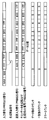
- FIG. 3 is a diagram for explaining a detailed circuit configuration of the compare unit 21
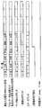
- FIG. 4 is a diagram for explaining an example of a comparison test start operation in the comparison circuit
- FIG. FIG. 6 is a diagram for explaining an example of an end operation when the test of the compare test is passed (Pass) in FIG. 6, and FIG. 6 is an example of an end operation when the test of the compare test is failed in the comparison circuit (Fail).
- FIG. 3 is a diagram for explaining a detailed circuit configuration of the compare unit 21
- FIG. 4 is a diagram for explaining an example of a comparison test start operation in the comparison circuit
- FIG. 6 is a diagram for explaining an example of an end operation when the test of the compare test is passed (Pass) in FIG. 6, and FIG. 6 is an example of an end operation when the test of the compare test is failed in the comparison circuit (Fail).
- FIG. 21 and the compare part 31 perform the operation
- the compare unit 21 includes a detection circuit 40, a delay circuit 41, and a comparison circuit 42.
- a PRBS (Pseudo Random Bit Sequence) 23 signal used for evaluating the transmission quality of a high-speed digital signal is generated as a test signal, and the generated PRBS23 signal is switched to the switching unit. 13, and input to the detection circuit 40 and the delay circuit 41 of the compare unit 21 via the parallel / LVDS transmission unit 14 and the serial / LVDS reception unit 20.
- the detection circuit 40 When the detection circuit 40 detects a predetermined data pattern from the input PRBS23 signal, the detection circuit 40 transmits a generation start signal (trigger signal) for starting generation of a test signal to the test signal generation unit 22.
- a generation start signal trigger signal
- the detection circuit 40 detects a continuous data pattern of “FFF” and “7FF” from the input PRBS23 signal, and generates a generation start signal.
- the test signal generation unit 22 When the generation start signal is input from the detection circuit 40 of the compare unit 21, the test signal generation unit 22 generates and generates a data pattern (PRBS23 signal) in the same order as the PRBS23 signal input to the compare unit 21.
- the PRBS23 signal is output to the comparison circuit 42.
- the delay circuit 41 delays the input PRBS23 signal for a predetermined period, for example, 2 clocks, and outputs the PRBS23 signal delayed by 2 clocks to the comparison circuit 42.
- the comparison circuit 42 compares the PRBS23 signal generated by the test signal generation unit 22 with the PRBS23 signal input from the delay circuit 41 after the generation start signal is generated in the detection circuit 40. Then, it is confirmed whether or not they match with a predetermined amount of data.
- the comparison circuit 42 includes a counter that counts the number of compared data, a counter that counts the number of matched data, and an error counter that counts the number of errors by subtracting the number of matches from the number of compared data.
- the comparison circuit 42 detects whether or not the number of errors of the error counter is 0, and outputs the detection result as a determination signal (comparison result) indicated by 0 (Low) or 1 (High). For example, when the number of errors is 0, the comparison circuit 42 outputs a determination signal of 1 (High) indicating that the test has passed (Pass). When the number of errors is 1 or more, the test fails (Fail). A determination signal of 0 (Low) indicating that the error has occurred is output.
- the comparison circuit 42 determines whether the test has passed (Pass) or failed (Fail) based on whether the number of errors is 0, but the determination is not limited to this, and a determination is made using a predetermined threshold. You may do it. Specifically, for example, when the number of errors in the error counter is less than a predetermined error number (predetermined threshold), the comparison circuit 42 determines that the test has passed and the error number is equal to the predetermined error number ( If it is equal to or greater than a predetermined threshold value, it is determined that the test has failed.
- predetermined threshold a predetermined error number
- a comparison operation completion signal is input to the comparison circuit 42 after the n data comparisons are performed.
- the comparison operation completion signal is output from the counter when the counter for counting the number of data reaches n.
- the comparison circuit 42 confirms the number of errors in the error counter. In the case of the example shown in FIG. 5, the comparison circuit 42 outputs a 1 (High) determination signal indicating that the test has passed (Pass) because the number of errors in the error counter is 0. On the other hand, in the example shown in FIG. 6, the comparison circuit 42 outputs a 0 (Low) determination signal indicating that the test has failed (Fail) because the number of errors in the error counter is 1.
- the endoscope system 1 performs the bit error rate test between the head unit 4a of the camera head 4 and the connector unit 4c in the compare unit 21, and the connector unit 4c and the CCU 5 in the compare unit 31. A bit error rate test is performed during this period. Thereby, the endoscope system 1 determines whether there is a transmission error between the head unit 4a and the connector unit 4c, and whether there is a transmission error between the connector unit 4c and the CCU 5. .
- the endoscope system 1 can perform a bit error rate test between the head unit 4a and the connector unit 4c and between the connector unit 4c and the CCU 5, there is an error when the imaging signal is transmitted. In this case, it is possible to reliably determine where the error has occurred.
- bit error rate test is executed from the personal computer 8
- the specifications of the bit error rate test are prepared in the CCU 5
- the bit error rate test is selected from the menu of the CCU 5
- the test execution, the result display It is good also as a structure which can be recorded.
- FIG. 7 is a diagram showing a detailed circuit configuration of the camera head and camera control unit of the endoscope system according to the second embodiment.
- the same components as those in FIG. 2 are denoted by the same reference numerals and description thereof is omitted.
- the endoscope system 1a is configured using a connector portion 4d instead of the connector portion 4c of FIG.
- the connector unit 4d is configured to include an amplifier 27 in the preceding stage of the serial / LVDS receiving unit 20.
- the signal transmitted from the Parasiri / LVDS transmission unit 14 deteriorates while the cable 4b is transmitted.
- the amplifier 27 amplifies the signal deteriorated during transmission through the cable 4 b and outputs the amplified signal to the serial / LVDS receiver 20.
- the connector part 4d is the structure which has the amplifier 27, it is not limited to this, for example, the structure which the head part 4a has the amplifier 27 may be sufficient. More specifically, an amplifier 27 is provided at the subsequent stage of the parasiri / LVDS transmission unit 14 to amplify the signal transmitted from the parasiri / LVDS transmission unit 14 and then perform transmission using the cable 4b. Other configurations and operations are the same as those in the first embodiment.
- FIG. 8 is a diagram for explaining the configuration of the connector portion 4d.
- the connector portion 4d has a plurality of connection pins 50a, 50b, 50c,... For electrically connecting to the CCU 5.
- ESD electrostatic discharge
- an ESD protection member is provided for protecting internal circuits and ICs from the ESD.
- connection pin 50b is connected to the circuit unit 51, in order to protect the circuit unit 51 from ESD, the connection pin 50b is configured by an ESD protection diode or a varistor or the like in the immediate vicinity of the connection pin 50b.
- An ESD protection member 52 is provided.
- connection pin 50b the circuit unit 51 may not be protected. Further, the ESD applied to the unused connection pin 50 a may wrap around the connection line connecting the connection pin 50 b and the circuit unit 51.
- the circuit unit 51 can be protected even when the size ESD is applied to the connection pin 50b or when the ESD applied to the unused connection pin 50a wraps around the connection line.
- the ESD protection member 53 is provided in the immediate vicinity of the circuit unit 51.
- the ESD protection member 54 is also provided on the unused connection pin 50c.
- illustration is abbreviate
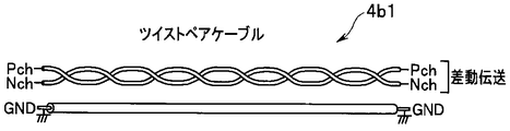
- FIG. 9A is a diagram for explaining the configuration of the twisted pair cable
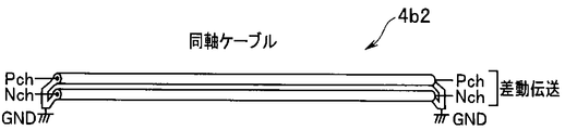
- FIG. 9B is a diagram for explaining the configuration of the coaxial cable.
- a twisted pair cable 4b1 in which two single wires are twisted and paired is used as shown in FIG. 9A.
- Pch is connected to one of the pair and Nch is connected to the other, and the differential impedance between the pair is designed to be 100 ⁇ .
- the twisted pair cable 4b1 requires a single GND line in addition to the two lines of Pch and Nch.
- the image pickup signal from the head portion 4a is transmitted to the connector portion 4d and the CCU 5 by a digital differential signal.
- the increase in the transmission rate due to the increase in the number of pixels of the image pickup device 10 and the increase in the number of plates has become remarkable.
- the technical hurdles of transmission are high. In order to support high-speed transmission, it is a conventional technique to make the cable itself thicker or divide the data to be transmitted, increase the number of lanes, and lower the transmission rate per line.
- the twisting pitch of the twisted pair cable 4b1 is fine, the distance between the pairs does not change, but the twisted pair cable 4b1 itself becomes hard and the handling becomes worse.
- the number of twisted pair cables 4b1 increases accordingly, and the total cable diameter becomes thicker.
- the total cable diameter becomes thick the total cable becomes hard and the handling becomes worse.
- a poor handling leads to a user disadvantage. Therefore, with the camera head 4 that is bent or moved without fixing the cable 4b, the twisted pair cable 4b1 may not be able to exhibit sufficient performance.
- differential transmission is performed using the coaxial cable 4b2 shown in FIG. 9B instead of the twisted pair cable 4b1 shown in FIG. 9A. That is, the digital differential transmission of the camera head 4 is performed by the two coaxial cables 4b2 instead of the twisted pair cable 4b1. Even if the coaxial cable 4b2 is bent, the single characteristic impedance is not disturbed. Moreover, since the coaxial cable 4b2 is shielded for each cable, the disturbance resistance is higher than that of the twisted pair cable 4b1.
- the GND when high-speed transmission is required and the number of lanes is increased, by using the coaxial cable 4b2, the GND can be secured by the shield of the coaxial cable 4b2, and therefore, the single GND line of the twisted pair cable 4b1 can be deleted. As a result, even if the number of lanes is increased, the influence on the total diameter of the cable 4b is small, and the handling property can be ensured.
- the single-wire GND line of the twisted pair cable 4b1 can be eliminated by using the coaxial cable 4b2, and the high-speed transmission and the cable 4b can be eliminated.
- the diameter can be reduced at the same time.
- an error can be identified for each transmission lane by executing a bit error rate test for each transmission lane.
Abstract
Description
図1は、第1の実施形態に係る内視鏡システムの構成を示す図であり、図2は、第1の実施形態に係る内視鏡システムのカメラヘッド及びカメラコントロールユニットの詳細な回路構成を示す図である。 (First embodiment)
FIG. 1 is a diagram illustrating a configuration of an endoscope system according to the first embodiment, and FIG. 2 is a detailed circuit configuration of a camera head and a camera control unit of the endoscope system according to the first embodiment. FIG.
次に、第2の実施形態について説明する。 (Second Embodiment)
Next, a second embodiment will be described.
Claims (4)
- 撮像素子を有するヘッド部と、前記ヘッド部とケーブルを介して一体的に接続されたコネクタ部とを有するヘッド分離型カメラ装置と、前記コネクタ部を介して前記ヘッド分離型カメラ装置と着脱自在な信号処理装置とを有する内視鏡システムであって、
前記ヘッド部は、
第1のテストパターン信号を生成する第1のテストパターン生成部と、
前記第1のテストパターン生成部で生成された前記第1のテストパターン信号を前記ケーブルを介して送信する第1の送信部と、を有し、
前記コネクタ部は、
前記第1の送信部から送信された前記第1のテストパターン信号を受信する第1の受信部と、
前記第1の受信部で受信された前記第1のテストパターン信号から所定のデータパターンを検出し、第1の生成開始信号を出力する第1の検出回路と、
前記第1の生成開始信号に基づいて前記第1のテストパターンと同じパターン信号である第2のテストパターン信号を生成する第2のテストパターン生成部と、
前記第1のテストパターン信号と前記第2のテストパターン信号とを比較した比較結果を出力する第1の比較回路と、
第3のテストパターン信号を生成する第3のテストパターン生成部と、
前記第3のテストパターン生成部で生成された前記第3のテストパターン信号を送信する第2の送信部と、を有し、
前記信号処理装置は、
前記第2の送信部から送信された前記第3のテストパターン信号を受信する第2の受信部と、
前記第2の受信部で受信された前記第3のテストパターン信号から所定のデータパターンを検出し、第2の生成開始信号を出力する第2の検出回路と、
前記第2の生成開始信号に基づいて前記第3のテストパターンと同じパターン信号である第4のテストパターン信号を生成する第4のテストパターン生成部と、
前記第3のテストパターン信号と前記第4のテストパターン信号とを比較した比較結果を出力する第2の比較回路と、
を有することを特徴とする内視鏡システム。 A head-separated camera device having a head unit having an image sensor and a connector unit integrally connected to the head unit via a cable, and detachable from the head-separated camera device via the connector unit An endoscope system having a signal processing device,
The head portion is
A first test pattern generation unit for generating a first test pattern signal;
A first transmitter that transmits the first test pattern signal generated by the first test pattern generator via the cable;
The connector part is
A first receiver for receiving the first test pattern signal transmitted from the first transmitter;
A first detection circuit that detects a predetermined data pattern from the first test pattern signal received by the first reception unit and outputs a first generation start signal;
A second test pattern generation unit that generates a second test pattern signal that is the same pattern signal as the first test pattern based on the first generation start signal;
A first comparison circuit for outputting a comparison result obtained by comparing the first test pattern signal and the second test pattern signal;
A third test pattern generation unit for generating a third test pattern signal;
A second transmission unit for transmitting the third test pattern signal generated by the third test pattern generation unit,
The signal processing device includes:
A second receiver for receiving the third test pattern signal transmitted from the second transmitter;
A second detection circuit that detects a predetermined data pattern from the third test pattern signal received by the second reception unit and outputs a second generation start signal;
A fourth test pattern generation unit that generates a fourth test pattern signal that is the same pattern signal as the third test pattern based on the second generation start signal;
A second comparison circuit for outputting a comparison result obtained by comparing the third test pattern signal and the fourth test pattern signal;
An endoscope system comprising: - 前記ヘッド部は、前記撮像信号と前記第1のテストパターン信号とを切り替えて前記第1の送信部に出力する第1の切替部を有し、
前記コネクタ部は、前記撮像信号と前記第3のテストパターン信号とを切り替えて前記第2の送信部に出力する第2の切替部を有し、
前記第1の送信部は、前記撮像信号または前記第1のテストパターン信号を前記ケーブル介して前記第1の受信部に送信し、
前記第2の送信部は、前記撮像信号または前記第3のテストパターン信号を前記第2の受信部に送信することを特徴とする請求項1に記載の内視鏡システム。 The head unit includes a first switching unit that switches the imaging signal and the first test pattern signal to output to the first transmission unit,
The connector unit includes a second switching unit that switches between the imaging signal and the third test pattern signal and outputs the switched signal to the second transmission unit.
The first transmission unit transmits the imaging signal or the first test pattern signal to the first reception unit via the cable,
The endoscope system according to claim 1, wherein the second transmission unit transmits the imaging signal or the third test pattern signal to the second reception unit. - 前記第1の送信部は、前記撮像信号または前記第1のテストパターン信号を差動シリアルデータに変換し、前記ケーブルを介して出力し、
前記ケーブルは、前記差動シリアルデータを伝送するための2本一対の同軸ケーブルであることを特徴とする請求項2に記載の内視鏡システム。 The first transmission unit converts the imaging signal or the first test pattern signal into differential serial data, and outputs the differential serial data via the cable.
The endoscope system according to claim 2, wherein the cable is a pair of coaxial cables for transmitting the differential serial data. - 前記第1のテストパターン信号は、ビットエラーレート試験用の試験信号であることを特徴とする請求項1に記載の内視鏡システム。 The endoscope system according to claim 1, wherein the first test pattern signal is a test signal for a bit error rate test.
Priority Applications (4)
| Application Number | Priority Date | Filing Date | Title |
|---|---|---|---|
| CN201580033559.7A CN106455953B (en) | 2015-03-26 | 2015-09-17 | Endoscopic system |
| JP2016509179A JP6013650B1 (en) | 2015-03-26 | 2015-09-17 | Endoscope system |
| EP15886445.4A EP3138469A4 (en) | 2015-03-26 | 2015-09-17 | Endoscope system |
| US15/379,750 US9775498B2 (en) | 2015-03-26 | 2016-12-15 | Endoscope system |
Applications Claiming Priority (2)
| Application Number | Priority Date | Filing Date | Title |
|---|---|---|---|
| JP2015-064540 | 2015-03-26 | ||
| JP2015064540 | 2015-03-26 |
Related Child Applications (1)
| Application Number | Title | Priority Date | Filing Date |
|---|---|---|---|
| US15/379,750 Continuation US9775498B2 (en) | 2015-03-26 | 2016-12-15 | Endoscope system |
Publications (1)
| Publication Number | Publication Date |
|---|---|
| WO2016151893A1 true WO2016151893A1 (en) | 2016-09-29 |
Family
ID=56977924
Family Applications (1)
| Application Number | Title | Priority Date | Filing Date |
|---|---|---|---|
| PCT/JP2015/076516 WO2016151893A1 (en) | 2015-03-26 | 2015-09-17 | Endoscope system |
Country Status (5)
| Country | Link |
|---|---|
| US (1) | US9775498B2 (en) |
| EP (1) | EP3138469A4 (en) |
| JP (1) | JP6013650B1 (en) |
| CN (1) | CN106455953B (en) |
| WO (1) | WO2016151893A1 (en) |
Families Citing this family (3)
| Publication number | Priority date | Publication date | Assignee | Title |
|---|---|---|---|---|
| WO2019058637A1 (en) * | 2017-09-19 | 2019-03-28 | オリンパス株式会社 | Endoscope and endoscope system |
| JP2019176334A (en) * | 2018-03-28 | 2019-10-10 | ソニーセミコンダクタソリューションズ株式会社 | Solid-state image sensor, test system, and control method for solid-state image sensor |
| JP7102551B2 (en) * | 2019-01-09 | 2022-07-19 | オリンパス株式会社 | Imaging system and operating method |
Citations (4)
| Publication number | Priority date | Publication date | Assignee | Title |
|---|---|---|---|---|
| JPH07171096A (en) * | 1993-12-17 | 1995-07-11 | Olympus Optical Co Ltd | Automatic regulator of signal processor for endoscope |
| JP2005296467A (en) * | 2004-04-14 | 2005-10-27 | Olympus Corp | Display controller for stereoscopic endoscope |
| JP2011206185A (en) * | 2010-03-29 | 2011-10-20 | Fujifilm Corp | Endoscope system and failure detection method of the same |
| WO2014002732A1 (en) * | 2012-06-27 | 2014-01-03 | オリンパスメディカルシステムズ株式会社 | Imaging device and imaging system |
Family Cites Families (12)
| Publication number | Priority date | Publication date | Assignee | Title |
|---|---|---|---|---|
| JP2002199291A (en) | 2000-12-27 | 2002-07-12 | Olympus Optical Co Ltd | Image pickup device |
| JP4761882B2 (en) * | 2005-08-10 | 2011-08-31 | オプティスキャン ピーティーワイ リミテッド | Scanning confocal endoscope system and image display range adjustment method of the system |
| JP2007215907A (en) * | 2006-02-20 | 2007-08-30 | Pentax Corp | Endoscope processor, endoscopic system and black balance adjustment program |
| JP2009148552A (en) * | 2007-11-27 | 2009-07-09 | Hoya Corp | Radio observation device and endoscope system |
| JP2009201540A (en) * | 2008-02-26 | 2009-09-10 | Fujinon Corp | Imaging system and endoscope system |
| JP5464815B2 (en) * | 2008-03-25 | 2014-04-09 | オリンパスメディカルシステムズ株式会社 | Imaging system and operation method of self-check processing of imaging system |
| JP5162374B2 (en) * | 2008-08-21 | 2013-03-13 | 富士フイルム株式会社 | Endoscopic image deviation amount measuring apparatus and method, electronic endoscope and endoscope image processing apparatus |
| US8040374B2 (en) * | 2009-08-31 | 2011-10-18 | Kabushiki Kaisha Toshiba | Head separated camera apparatus |
| DE102011106386A1 (en) * | 2011-07-04 | 2013-01-10 | Karl Storz Gmbh & Co. Kg | Endoscopic arrangement |
| CN103384492B (en) * | 2011-09-22 | 2015-12-02 | 奥林巴斯株式会社 | Endoscope |
| JP5872911B2 (en) * | 2012-01-16 | 2016-03-01 | オリンパス株式会社 | Imaging unit and imaging system |
| JP5904829B2 (en) * | 2012-03-12 | 2016-04-20 | オリンパス株式会社 | Endoscope system |
-
2015
- 2015-09-17 WO PCT/JP2015/076516 patent/WO2016151893A1/en active Application Filing
- 2015-09-17 JP JP2016509179A patent/JP6013650B1/en active Active
- 2015-09-17 EP EP15886445.4A patent/EP3138469A4/en not_active Withdrawn
- 2015-09-17 CN CN201580033559.7A patent/CN106455953B/en active Active
-
2016
- 2016-12-15 US US15/379,750 patent/US9775498B2/en active Active
Patent Citations (4)
| Publication number | Priority date | Publication date | Assignee | Title |
|---|---|---|---|---|
| JPH07171096A (en) * | 1993-12-17 | 1995-07-11 | Olympus Optical Co Ltd | Automatic regulator of signal processor for endoscope |
| JP2005296467A (en) * | 2004-04-14 | 2005-10-27 | Olympus Corp | Display controller for stereoscopic endoscope |
| JP2011206185A (en) * | 2010-03-29 | 2011-10-20 | Fujifilm Corp | Endoscope system and failure detection method of the same |
| WO2014002732A1 (en) * | 2012-06-27 | 2014-01-03 | オリンパスメディカルシステムズ株式会社 | Imaging device and imaging system |
Non-Patent Citations (1)
| Title |
|---|
| See also references of EP3138469A4 * |
Also Published As
| Publication number | Publication date |
|---|---|
| US9775498B2 (en) | 2017-10-03 |
| JPWO2016151893A1 (en) | 2017-04-27 |
| EP3138469A1 (en) | 2017-03-08 |
| CN106455953B (en) | 2018-01-30 |
| US20170095141A1 (en) | 2017-04-06 |
| CN106455953A (en) | 2017-02-22 |
| JP6013650B1 (en) | 2016-10-25 |
| EP3138469A4 (en) | 2018-01-24 |
Similar Documents
| Publication | Publication Date | Title |
|---|---|---|
| JP6013650B1 (en) | Endoscope system | |
| US8896680B2 (en) | Endoscope with first and second voltage comparing portions | |
| JP5642484B2 (en) | Endoscope system | |
| JP5356632B1 (en) | Imaging system | |
| US9936864B2 (en) | Image pickup apparatus and electronic endoscope system | |
| US20160295141A1 (en) | Endoscope system | |
| US20180296065A1 (en) | Endoscope device | |
| JP5290474B2 (en) | Endoscope device | |
| US20160374538A1 (en) | Electronic endoscope | |
| WO2016088421A1 (en) | Endoscope | |
| WO2017145418A1 (en) | Endoscope system and method for operating endoscope system | |
| JP2005305124A (en) | Electronic endoscope apparatus | |
| JP2005160925A (en) | Electronic endoscope apparatus | |
| JP6033523B1 (en) | Imaging apparatus and electronic endoscope system | |
| JP6833495B2 (en) | Endoscope | |
| JPWO2016117373A1 (en) | Medical equipment and endoscope system | |
| JP2008125590A (en) | Endoscopic apparatus | |
| JP2011254421A (en) | Signal transmitter and electronic endoscope | |
| JP5340854B2 (en) | Endoscope, endoscope device | |
| JPWO2017145418A1 (en) | Endoscope system and operation method of endoscope system | |
| JP2016112175A (en) | Endoscope apparatus | |
| JP2013172766A (en) | Signal cable and endoscope apparatus | |
| JP2019150466A (en) | Medical equipment | |
| JP2003230537A (en) | Processor for electronic endoscopic device |
Legal Events
| Date | Code | Title | Description |
|---|---|---|---|
| ENP | Entry into the national phase |
Ref document number: 2016509179 Country of ref document: JP Kind code of ref document: A |
|
| 121 | Ep: the epo has been informed by wipo that ep was designated in this application |
Ref document number: 15886445 Country of ref document: EP Kind code of ref document: A1 |
|
| REEP | Request for entry into the european phase |
Ref document number: 2015886445 Country of ref document: EP |
|
| WWE | Wipo information: entry into national phase |
Ref document number: 2015886445 Country of ref document: EP |
|
| NENP | Non-entry into the national phase |
Ref country code: DE |