JP2005296467A - Display controller for stereoscopic endoscope - Google Patents
Display controller for stereoscopic endoscope Download PDFInfo
- Publication number
- JP2005296467A JP2005296467A JP2004119484A JP2004119484A JP2005296467A JP 2005296467 A JP2005296467 A JP 2005296467A JP 2004119484 A JP2004119484 A JP 2004119484A JP 2004119484 A JP2004119484 A JP 2004119484A JP 2005296467 A JP2005296467 A JP 2005296467A
- Authority
- JP
- Japan
- Prior art keywords
- display
- signal
- output
- displayed
- display control
- Prior art date
- Legal status (The legal status is an assumption and is not a legal conclusion. Google has not performed a legal analysis and makes no representation as to the accuracy of the status listed.)
- Withdrawn
Links
- 238000012360 testing method Methods 0.000 claims abstract description 55
- 238000003384 imaging method Methods 0.000 claims description 25
- 238000012544 monitoring process Methods 0.000 claims description 14
- 238000012545 processing Methods 0.000 claims description 12
- 238000001444 catalytic combustion detection Methods 0.000 abstract description 57
- 230000003287 optical effect Effects 0.000 abstract description 37
- 230000015654 memory Effects 0.000 description 70
- 235000019557 luminance Nutrition 0.000 description 18
- 238000012937 correction Methods 0.000 description 15
- 238000012986 modification Methods 0.000 description 12
- 230000004048 modification Effects 0.000 description 12
- 238000000926 separation method Methods 0.000 description 12
- 238000003780 insertion Methods 0.000 description 11
- 230000037431 insertion Effects 0.000 description 11
- 238000010586 diagram Methods 0.000 description 9
- 238000005286 illumination Methods 0.000 description 7
- 238000000034 method Methods 0.000 description 5
- 230000000694 effects Effects 0.000 description 4
- 230000005540 biological transmission Effects 0.000 description 2
- 238000006243 chemical reaction Methods 0.000 description 2
- 238000007689 inspection Methods 0.000 description 2
- 125000002066 L-histidyl group Chemical group [H]N1C([H])=NC(C([H])([H])[C@](C(=O)[*])([H])N([H])[H])=C1[H] 0.000 description 1
- 230000002159 abnormal effect Effects 0.000 description 1
- 239000003086 colorant Substances 0.000 description 1
- 238000001816 cooling Methods 0.000 description 1
- 238000001514 detection method Methods 0.000 description 1
- 238000003745 diagnosis Methods 0.000 description 1
- 239000004973 liquid crystal related substance Substances 0.000 description 1
- 230000007774 longterm Effects 0.000 description 1
- 230000001151 other effect Effects 0.000 description 1
- 230000002123 temporal effect Effects 0.000 description 1
Images


Landscapes
- Instruments For Viewing The Inside Of Hollow Bodies (AREA)
- Endoscopes (AREA)
- Closed-Circuit Television Systems (AREA)
- Testing, Inspecting, Measuring Of Stereoscopic Televisions And Televisions (AREA)
Abstract
Description
本発明は、立体観察による内視鏡検査を行うことが可能な立体内視鏡装置に関する。 The present invention relates to a stereoscopic endoscope apparatus capable of performing an endoscopic inspection by stereoscopic observation.
近年、内視鏡は医療用分野及び工業用分野において、広く採用されるようになった。また、立体映像により内視鏡観察或いは内視鏡検査を行うことができるように、左右に対となる2つの撮像光学系を設けた立体内視鏡が提案されている。
この場合、例えば左右の画像を交互に1台のモニタ表示し、左右の画像に対応して、交互に開閉するシャッタを通して観察する事で、立体に観察する方法や、左右別々の画像を表示する2台のモニタを用いて、左右の目で観察する方法などがある。
これらの方法を用いた場合、片側のモニタや、映像ケーブルなどが故障すると、左右の目が異なる画像を観察するため、観察者は、疲労し易くなる事がある。
特開平6−261341号公報では、上記問題を解決するために、映像ケーブルの断線を検知し、断線していない画像により補う方法を開示している。
In this case, for example, the left and right images are alternately displayed on one monitor, and the images are observed through a shutter that opens and closes alternately corresponding to the left and right images. There is a method of observing with the left and right eyes using two monitors.
When these methods are used, if a monitor on one side, a video cable, or the like breaks down, the left and right eyes observe different images, and thus the observer may be easily fatigued.
Japanese Patent Application Laid-Open No. 6-261341 discloses a method for detecting the disconnection of the video cable and compensating for it with an image that is not disconnected in order to solve the above problem.
しかしながら、上記公報の従来例では、左右のモニタでの表示特性が変化した場合における左右の画像のばらつきを解決することができない。そのために、観察者は、違和感を感じたり、疲労し易くなる事がある。
また、上記従来例においては、左右の2つの撮像手段による特性にばらつきが発生すると、やはりモニタ上に表示される左右の画像のばらつきとなってしまい、観察者は、違和感を感じたり、疲労し易くなる事がある。
However, in the conventional example of the above publication, the variation in the left and right images when the display characteristics on the left and right monitors change cannot be solved. Therefore, the observer may feel uncomfortable or easily get tired.
In the above conventional example, if the characteristics of the left and right imaging means vary, the left and right images displayed on the monitor also vary, and the observer feels uncomfortable or tired. It may be easier.
(発明の目的)
発明は上述した点に鑑みてなされたもので、表示装置に表示される左右の画像のばらつきを低減して、違和感の少ない表示を行うことができる立体内視鏡用表示制御装置を提供することを目的とする。
(Object of invention)
The present invention has been made in view of the above-described points, and provides a stereoscopic endoscope display control device capable of reducing a variation in left and right images displayed on a display device and performing a display with less discomfort. With the goal.
本発明は、同一被写体に対して立体内視鏡により撮像された少なくとも左右に視差を有する2つの撮像信号に対する信号処理を行い、表示手段に対して立体観察用の左右の画像を送出する立体内視鏡用表示制御装置において、
前記表示手段における少なくとも一部にテスト信号を表示させるテスト信号発生手段と、
前記表示手段に表示される前記テスト信号の表示状態を監視する監視手段と、
前記監視手段の出力に基づき、前記表示手段による左右の画像表示を制御する表示制御手段と、
を具備したことを特徴とする。
上記構成により、上記表示手段に表示される左右の画像にばらつきが発生しても、上記表示制御手段によりばらつきを軽減する画像表示を行う制御をすることにより、違和感の少ない立体観察用の画像表示を行えるようにしている。
The present invention performs signal processing on at least two imaging signals having parallax on the left and right sides taken by a stereoscopic endoscope with respect to the same subject, and sends left and right images for stereoscopic observation to a display means. In an endoscope display control device,
Test signal generating means for displaying a test signal on at least a part of the display means;
Monitoring means for monitoring a display state of the test signal displayed on the display means;
Display control means for controlling left and right image display by the display means based on the output of the monitoring means;
It is characterized by comprising.
With the above-described configuration, even if the left and right images displayed on the display unit vary, the display control unit controls the image display to reduce the variation, thereby reducing the sense of discomfort for stereoscopic display. Can be done.
本発明によれば、立体観察用の左右の画像を表示する表示手段に表示される左右の画像にばらつきが発生しても、違和感の少ない立体観察用の画像表示を行える。 According to the present invention, even when the left and right images displayed on the display means for displaying the left and right images for stereoscopic observation vary, it is possible to display an image for stereoscopic observation with less sense of incongruity.
以下、図面を参照して本発明の実施例を説明する。 Embodiments of the present invention will be described below with reference to the drawings.
図1ないし図12は本発明の実施例1に係り、図1は本発明の実施例1の立体内視鏡装置の全体構成を示し、図2は信号切替装置の内部構成を示し、図3は信号切替装置の動作説明のタイミングチャ−トを示し、図4は表示制御装置の内部構成を示し、図5は表示装置の内部構成を平面図により示し、図6は図5の側面側から見た概略の構成を示し、図7は図5の接眼部付近の構成及び変形例の構成を示す。
また、図8はワイド用表示素子における通常時の表示画面例を示し、図9はワイド用表示素子における切替時の表示画面例を示し、図10は左右の表示素子における通常時の表示画面例を示し、図11は比較装置の内部構成を示し、図12は変形例における比較装置の内部構成を示す。
1 to 12 relate to the first embodiment of the present invention, FIG. 1 shows the overall configuration of the stereoscopic endoscope apparatus of the first embodiment of the present invention, FIG. 2 shows the internal configuration of the signal switching device, and FIG. Shows a timing chart for explaining the operation of the signal switching device, FIG. 4 shows the internal configuration of the display control device, FIG. 5 shows the internal configuration of the display device in a plan view, and FIG. 6 is a side view of FIG. FIG. 7 shows a schematic configuration as seen, and FIG. 7 shows a configuration in the vicinity of the eyepiece in FIG.
8 shows an example of a normal display screen in the wide display element, FIG. 9 shows an example of a display screen at the time of switching in the wide display element, and FIG. 10 shows an example of a normal display screen in the left and right display elements. FIG. 11 shows the internal configuration of the comparison device, and FIG. 12 shows the internal configuration of the comparison device in the modification.
図1に示すように本発明の実施例1の立体内視鏡装置1は、立体撮像を行う立体内視鏡2と、立体内視鏡2に照明光を供給する光源装置3と、立体内視鏡2の撮像手段に対する信号処理を行う信号処理装置4と、信号切替を行う信号切替装置5と、表示制御を行う表示制御装置部6と、画像表示を行う表示装置7と、左右の画像表示の差異を検出する比較装置8とを有する。
立体内視鏡2は、被写体の光学像を結像する光学系を先端に設けた細長の挿入部11、この挿入部11の後端に設けられ、術者等が把持する把持部12、この把持部12の後端に設けられた接眼部13とを有する光学式内視鏡14と、この接眼部13に着脱自在に装着され、撮像手段を内蔵したテレビカメラ15とから構成される。
図1においては、立体内視鏡2を光学式内視鏡14と、テレビカメラ15とにより構成したものを採用しているが、撮像手段を光学系の結像位置に配置した立体電子内視鏡により構成しても良い。
As shown in FIG. 1, a
The stereoscopic endoscope 2 includes an elongated insertion portion 11 provided with an optical system for forming an optical image of a subject at the tip, a
In FIG. 1, the stereoscopic endoscope 2 is configured by an
立体内視鏡2における挿入部11内には、照明光伝送手段としてのライトガイド16が挿通されており、このライトガイド16の後端のライトガイド口金にはライトガイドケーブル17を介して光源装置3からの照明光が供給される。このライトガイド16は、挿入部11の先端部18に設けた照明窓にその先端面(出射端面)が固定されており(図1では省略)、その先端面からさらに照明レンズを経て照明光を出射し、この照明光により挿入部11が挿入される体腔内の患部等の被写体を照明する。
立体内視鏡2における挿入部11の先端部18には、照明された(同一の)被写体に対して、左右方向において視差をもって結像するように、左右に離間して配置された左用の対物光学系21Lと右用の対物光学系21Rと、これら左右用の対物光学系21L,21Rにより得られる被写体像より広い結像範囲で結像する広角或いはワイド(W)用の対物光学系21Wとが配置されている。
A
At the
左右用及び広角用の対物光学系21L、21R、21Wによる各光学像は、挿入部11内に挿通されたリレー光学系22L、22R、22Wによりそれぞれ後方側に伝送され、接眼部13に配置された接眼光学系23を経て肉眼で観察することができる。なお、図1においては、リレー光学系22L、22R、22Wに対向して配置された3つの接眼レンズを接眼光学系23にて代表して示している。
図1に示すように接眼部13にテレビカメラ15が装着されると、接眼光学系23に対向してテレビカメラ15内に設けられた結像光学系24により、それぞれの結像位置に配置された撮像手段としての電荷結合素子(CCDと略記)25L、25R、25Wに結像される。
つまり、左右用及び広角用の対物光学系21L、21R、21Wによる各光学像は、リレー光学系22L、22R、22W等を介して左右用及び広角用のCCD25L、25R、25Wにそれぞれ結像され、それぞれ光電変換される。
The optical images by the left and right objective
As shown in FIG. 1, when the
That is, the respective optical images by the left and right objective
これらCCD25L、25R、25Wは、信号線を介して、信号処理装置4を形成するカメラコントロールユニット(CCUと略記)26L、26R、26Wにそれぞれ接続される。
左右用及び広角用のCCU26L、26R、26Wは、左右用及び広角用のCCD25L、25R、25Wにより光電変換されて出力される撮像信号に対して、映像信号に変換する信号処理を行う。
これらCCU26L、26R、26Wから出力信号は、信号切替を行う信号切替装置5を介して表示制御装置部6を構成する表示制御装置27L、27R、27Wに入力される。各表示制御装置27L、27R、27Wの出力信号は、表示装置7における映像表示を行う例えば液晶モニタ(LCDと略記)等により形成される表示素子28L、28R、28Wにそれぞれ入力される。
The
The left and right and
Output signals from the
表示制御装置27L、27R、27Wは、信号切替装置5を介してCCU26L、26R、26Wから出力される映像信号を表示素子28L、28R、28Wに適合する信号にそれぞれ変換する。
この表示装置7における表示素子28L及び28Rの表示面付近には、表示素子28Rと表示素子28Lに表示される同一のテスト信号の画像の(表示状態を監視するために)少なくともその一部を撮影するCCD29L、29Rがそれぞれ配置されている。
また、本実施例においては、CCD29Rと、CCD29の出力信号を比較する比較装置8が設けてあり、この比較装置8の出力信号は、信号切替装置5に入力され、比較装置8の比較結果により信号切替装置5から出力される信号を切り替える。
より具体的に説明すると、比較装置8によって、CCD29R及びCCD29の出力信号における輝度信号成分を比較し、その比較による両信号差が所定値以上である場合にはその比較結果の出力信号により、信号切替装置5におけるワイド用の表示素子28Wに表示するための映像信号を切り替える。
The
In the vicinity of the display surfaces of the
In the present embodiment, the
More specifically, the luminance signal components in the output signals of the
つまり、通常時には、信号切替装置5は、ワイド用のCCD25Wで撮像したワイド用の映像信号を出力するが、比較装置8による比較出力によって、左右の映像信号を出力するように切り替え、従ってワイド用の表示素子28Wには左右の画像が隣接して表示される状態に切り替えられる。
このため、以下に説明するように信号切替装置5の内部には、左右の画像が例えば倍速で書き込まれる左右画像メモリを設け、比較装置8の出力信号により、この左右画像メモリに格納された左右の画像を読み出して、表示制御装置27Wを介してワイド用の表示素子28Wに出力する。
That is, in the normal state, the
For this reason, as will be described below, left and right image memories in which left and right images are written at a double speed, for example, are provided inside the
図2は信号切替装置5の内部構成を示す。
この信号切替装置5は、比較装置8の出力信号に基づき切り替えて出力するスイッチ31R、31W、31Lと、CCU26LとCCU29Rからの両映像信号を記録する左右画像メモリ32と、左右画像メモリ32の動作を制御するメモリコントローラ33と、左右画像メモリ32と、メモリコントローラ33の動作クロックを生成するタイミングジェネレータ(TGと略記)34とを有する。
また、スイッチ31Rは、CCU26Rからの出力信号(映像信号)を左右画像メモリ32に出力する場合と、表示制御装置27Rに出力する場合とを切り替える。またスイッチ31Lは、CCU26Lからの出力信号(映像信号)を左右画像メモリ32に出力する場合と、表示制御装置27Lに出力する場合とを切り替える。また、スイッチ31Wは、CCU26Wからの出力信号を表示制御装置27Wに出力する場合と、左右画像メモリ32からの出力信号を表示制御装置27Wに出力する場合とを切り替える。
FIG. 2 shows the internal configuration of the
The
The
TG34のクロックは、CCU26L、26Rから出力される映像信号における水平同期信号の倍速で左右画像メモリ32に左右の画像を書き込むことができるようにしている。そのタイミングチャートを図3に示す。
通常時における左右の映像信号は、図3(A)及び図3(B)のようになるが、CCD29R及びCCD29の出力信号に所定値以上に差があった場合には、左右のCCU26L、26Rからの映像信号は、図3(C)に示すように倍速(図3(A)及び図3(B)における水平1周期の1/2)で左右画像メモリ32に書き込まれる。
つまり、図3(C)に示すようにCCU26Lの映像信号の第1ラインの信号L1は、倍速で左右画像メモリ32に書き込まれ、書き込みが終わった所で、CCU26Rの第1ラインの信号R1が同様に左右画像メモリ32に続けて書き込まれる。
次の第2ラインの信号L2、R2も同様に、表示素子28Wの1/2の水平周期の時間でCCU26L、26Rの順に最終ラインまで左右画像メモリ32に書き込まれる。
The clock of the
The left and right video signals in the normal state are as shown in FIGS. 3A and 3B, but when there is a difference between the output signals of the
That is, as shown in FIG. 3C, the signal L1 of the first line of the video signal of the
Similarly, the signals L2 and R2 of the next second line are written in the left and
左右画像メモリ32に書き込まれた順に、左右画像メモリ32から表示制御装置27Wに出力される。この場合、図3(D)に示すように出力クロックは、映像信号の水平同期信号と同じで、メモリコントローラ125を用いて、1ライン飛ばし(つまり、L1,R2、L3,R3、L5,R5、…)で左右画像メモリ32から表示制御装置27Wに出力される。
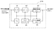
図4は表示制御装置27Rの詳細を示す。表示制御装置27Rは、信号切替装置5から出力されるアナログのビデオ信号をデジタル信号に変換するA/D変換器41と、A/D変換器41の出力を受け表示素子のフォーマットに合致するように、画素補間等の処理によりフォーマット変換を行うスケーラ42と、スケーラ42からの出力を画像1枚分のデータとして記憶する撮像画像メモリ43とを有する。
The images are output from the left and
FIG. 4 shows details of the
また、この表示制御装置27Rは、あらかじめテスト信号として、RGB信号系におけるRGBの出力レベルが同一となるような白色信号を記録したテスト画像メモリ44と、撮像画像メモリ43と、テスト画像メモリ44の動作を制御するメモリコントローラ45と、信号切替え装置5から出力される同期信号に基づいて前記A/D変換器41、スケーラ42、撮像画像メモリ43、テスト画像メモリ44に対して動作用クロックを印加するタイミングジェネレータ(TGと略記)46を有する。
In addition, the
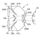
表示装置7の上面図を図5、側面図を図6、正面図を図7(A)に示す。表示装置7には、表示制御装置27Rの出力信号による映像を表示する表示素子28Rと、表示制御装置27Lの出力信号による映像を表示する表示素子28Lを有する。これらの映像は、光学系47R、48及び47L,48を介して接眼部49の接眼光学系50R、50Lに導かれる。
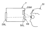
また接眼部49(の接眼光学系50R、50L)の上部には、表示制御装置27Wの出力信号による映像を表示する表示素子28Wが設けてある。この表示素子28Wは、観察者51が視線を上部に動かす事で観察できる位置に配置してある。
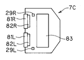
なお、図7(A)のように接眼部49の上部側に表示素子28Wを設けるものに限定されるものでなく、図7(B)に示すように接眼部49の下部側に表示素子28Wを設けるようにしても良い。
A top view of the
A
Note that the
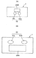
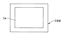
この表示素子28Wには、通常時には図8に示すようにCCU26Wの出力信号によるワイド映像Iwが全画面に表示される。この表示素子28Wには、切替時には、図9に示すようにCCU26L,26Rによる左右の映像Il,Irが左右に2画面表示する状態になる。
On the
さらにこの表示装置7には、左右の表示素子28L、表示素子28Rにおけるテスト信号を表示する表示領域(例えば図5の上面図で符号Itl、Itr、以下の図10の正面図で示す部分)の少なくとも一部を撮影できる位置にCCD29LとCCD29Rとが配置されている。CCD29LとCCD29Rの出力信号は、比較装置8に入力され、比較装置8による比較出力結果により、信号切替装置5の切り替え動作を制御する。
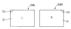
図10は表示素子28L、28Rにおけるテスト信号の表示領域例を示す。この例では表示素子28L、28Rの例えば4隅の1つの部分にテスト信号の表示領域Itl、Itrを設けている。そして、各表示領域Itl、Itrに対向してその表示状態を監視するための監視手段を形成するCCD29L,29Rが配置されている。
比較装置8の詳細を図11に示す。
Further, the
FIG. 10 shows an example of the display area of the test signal in the
Details of the
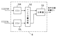
この比較装置8は、CCD29Rの信号を映像信号に変換するCCU51Rと、CCD29Lの信号を映像信号に変換するCCU51Lと、CCU51R、51Lからの出力信号を、輝度信号Yと色信号Cとに分離するY/C分離回路52と、Y/C分離回路52の輝度信号の出力を比較する比較器53とを有する。
この比較器53は、例えばウインドウ型コンパレータにより形成され、両輝度信号の出力差がある値以上になると、切り替えを行う切り替え信号を信号切替装置5に出力し、表示素子28Wには図9に示すように、この共通の表示素子28Wの画面上に、左右の画像の表示を行うようにして、(切り替え前よりも)左右の画像の表示状態の差を減少させるような画像表示を行う。
次に本実施例の作用を説明する。
信号切替装置5は、通常時は図1に示すように、CCU26Rの信号を表示制御装置27Rに、CCU26Lの信号を表示制御装置27Lに、CCU26Wの信号を表示制御装置27Wに出力するようにしてある。
The
The
Next, the operation of this embodiment will be described.
As shown in FIG. 1, the
そして、CCD26Rの信号は、表示素子28Rで、CCU26Lの信号は、表示素子28Lで、CCU26Wの信号は、表示素子28Wで観察できる。これにより、観察者は51は、表示素子28R、28Lを観察することで、立体観察ができ、また表示素子28Wを観察することで、ワイド画像を2次元で観察する事ができる。
図4に示す表示制御装置27R(27L、27Lも同じ構成)により、右CCD25R、左CCD25Lで撮影された映像を記憶する撮像画像メモリ43と、あらかじめテスト画像メモリ44に記憶したテスト信号の白色映像信号を、メモリコントローラ45により撮像画像メモリ43とテスト画像メモリ44の内容を切り替え、表示素子28R、28Lの一部分には白色映像を表示し、残りの部分には、右CCD25R、左CCD25Lで得られた映像を表示する事ができる。
The signal of the
A
テスト画像メモリ44は、RGB等の他の色を記憶しても良いし、輝度を複数変化させられるようにしても良い。
図4に示すように、一部分に表示したテスト信号を表示装置7に内蔵したCCD29R、CCD29Lにより撮影できる。また観察者51が上方に視線を動かすと、表示素子28Wの画像を観察することができる。
図11に示すようにCCU29R、29Lで撮像した白映像信号をCCU51R、51Lと、Y/C分離回路52を介する事で、輝度信号を電圧として得る事ができる。CCU51Rから得られる輝度信号と、CCU51Lから得られる輝度信号との差を求め、差が基準電圧(或いは閾値)より大きい場合は、例えばTTLレベルでHの信号を出力する。 差が基準電圧(或いは閾値)以下の時は、TTLレベルでLの信号が、比較装置8から出力され、スイッチ31R,31L,31Wは切り替わらず、図8に示すように、表示素子28Wは、CCU26Wからの映像信号を表示する。
The test image memory 44 may store other colors such as RGB, or may change a plurality of luminances.
As shown in FIG. 4, the test signal displayed in part can be photographed by the
As shown in FIG. 11, the luminance signal can be obtained as a voltage by passing white video signals captured by the
一方、輝度信号の差がしきい値以上の場合は、TTLレベルでHの信号が、比較装置8から出力され、スイッチ31R,31L,31Wが切り替わり、CCU26Rの信号と、CCU27Lの信号とがメモリコントローラ33によって、図3(C)のように制御される。
つまり、CCD26R、26Lの映像信号は、図3(A)或いは図3(B)に示す映像信号の水平同期信号の場合からその倍速のタイミングで左右画像メモリ32に書き込まれる。
また、左右画像メモリ32のデータは、メモリコントローラ33によって、図3(D)に示すように水平同期信号と同じ速度で、1ライン飛ばしで読み出しされ、表示制御装置27Wに入力される。そして、図9に示すように、アスペクト比が変化せず1つの表示素子28Wで左右の画像が表示され、観察者51が視線をずらせば、この表示素子28Wの画像を観察する事で、立体観察する事ができる。
On the other hand, when the difference between the luminance signals is equal to or greater than the threshold value, the TTL level H signal is output from the
That is, the video signals of the
Further, the data in the left and
本実施例では、一部分に常にテスト画像として、白信号を表示しているが、電源投入時や、チェック時等、限定的なタイミングで、テスト画像を表示し、切り替えを行っても良い。また、Y/C分離にて輝度信号を基準として比較に用いているが、色信号を比較しても良い。
本実施例は以下の効果を有する。
表示素子RとLの差が大きくなった事を検出し、表示素子を切替える事で、差異の大きい画像を観察しなくて良い。1枚の表示素子を代用するので、左右に表示される表示画像の差は減少する。また、画像が切り替わる事から、表示素子の異常と判断できるため、修理や買い替えなどの対応が取れ、差があるまま使用し続けるという事を避けられる。
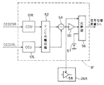
図12は変形例における比較装置8′の構成例を示す。この比較装置8′は、図10の比較装置8において、Y/C分離回路52の出力信号は減算器54を通して比較器56に入力されると共に、インバータ55を通して比較器56に入力される。
In the present embodiment, a white signal is always displayed as a test image in part, but the test image may be displayed and switched at a limited timing such as when the power is turned on or at the time of check. In addition, although the luminance signal is used as a reference in the Y / C separation, the color signal may be compared.
This embodiment has the following effects.
By detecting that the difference between the display elements R and L is increased and switching the display elements, it is not necessary to observe an image having a large difference. Since one display element is substituted, the difference between the display images displayed on the left and right is reduced. In addition, since the image is switched, it can be determined that the display element is abnormal. Therefore, it is possible to take measures such as repair and replacement, and avoid using the device with a difference.
FIG. 12 shows a configuration example of the
また、この比較器56には、基準電圧発生回路57から基準の電圧が印加される。つまり、この比較器56には、基準電圧発生回路57から基準の電圧が印加されており、この比較器56はY/C分離回路52側からの2つの信号における輝度信号のレベル差が、基準の電圧より大きいか否かを比較する。
そして、この比較器56の出力信号は、信号切替装置5に印加され、この比較器56の出力信号が、例えばHレベルになると、上述した実施例1と同様に信号切替装置5によるスイッチ31R、31L、31Wを切り替えるようにする。
また、減算器54の出力信号は、一方のCCU(ここではCCD26R)内の例えばCCD25Rからの(例えば色分離する前の)撮像信号を増幅するオートゲインコントロールアンプ(AGC)58のゲインコントロール端子に印加される。
A reference voltage is applied to the
Then, the output signal of the
The output signal of the
そして、この減算器54の出力信号により、このAGC58のゲインを可変制御し、他方のCCU26Lの信号レベルと一致するように制御する。この場合、AGC58のゲインコントロール端子によるゲイン制御の電圧レベル範囲が所定の値以内に設定されており、その値以上になると、AGC58のゲインは可変できないで最大値或いは最小値のままになる。
つまり、この変形例では、左右の表示素子28L,28Rにおけるテスト信号の例えば白レベルが異なっていると、例えばCCU26R側の信号レベルを(CCU26L側の信号レベルに)一致するようにゲイン調整する。このゲイン調整により、調整しきれない程度に白レベルが異なると、比較器56の出力信号により、実施例1のように信号切り替えを行う。
Then, the gain of the
That is, in this modification, when the white levels of the test signals in the left and
本変形例によれば、時間的或いは経年変化等により、左右のCCU26L,26Rや左右の表示素子28L,28Rの特性変化等により白レベルの差異が発生しても、その差異を補正して立体観察し易い状態で表示できる。その他は、実施例1と同様の効果を有する。
なお、比較装置8′においては、一方のCCU26RのAGC58のゲインを制御する場合で説明したが、他方のCCU26L側も同様に制御しても良い(例えばインバータ55の出力をCCU26L内のAGCのゲインを制御すれば良い)。
According to this modification, even if a difference in white level occurs due to a change in characteristics of the left and
In the
次に本発明の実施例2の立体内視鏡装置を図13から図15を参照して説明する。図13は、実施例2の立体内視鏡装置1Bの全体構成を示す。
この立体内視鏡装置1Bは、立体撮像を行う立体内視鏡2Bと、立体内視鏡2Bに照明光を供給する光源装置3と、立体内視鏡2Bの撮像手段に対する信号処理を行う信号処理装置4Bと、表示制御を行う表示制御装置部6Bと、画像表示を行う表示装置7Bとを有する。
立体内視鏡2Bは、被写体の光学像を結像する光学系を先端に設けた細長の挿入部11、この挿入部11の後端に設けられ、術者等が把持する把持部12、この把持部12の後端に設けられた接眼部13とを有する光学式内視鏡14Bと、この接眼部13に着脱自在に装着され、撮像手段を内蔵したテレビカメラ15Bとから構成される。
Next, a stereoscopic endoscope apparatus according to Embodiment 2 of the present invention will be described with reference to FIGS. FIG. 13 illustrates an overall configuration of the
The
The
この立体内視鏡2Bは、図1の立体内視鏡2において、ワイド用の対物光学系21Wを有しないで、左右用の対物光学系21L,21Rを備えた光学式内視鏡14Bと、やはりワイド用CCD25Wを有しないで、左右用のCCD25L,25Rを備えたテレビカメラ15Bとから構成されている。なお、ワイド用の対物光学系21Wを有しないので、リレー光学系22W等も備えていない。
また、信号処理装置4Bは、図1におけるCCU26Wを有しないで、CCU26L及びCCU26Rとから構成されている。また、同様に、表示制御装置部6Bは、図1の表示制御装置部6において、表示制御装置27Wを有しないで、2つの表示制御装置127L,127Rとから構成されている。
また、表示装置7Bは、図1の表示装置7において、ワイド用の表示素子28Wを有しないで、2つの表示素子28L,28Rと、2つのCCD29L,29Rとを有する。 図14は表示制御装置127R(127Lも同じ構成)の詳細を示す。
This
Further, the
Further, the display device 7B does not include the
表示制御装置127Rは、CCD25Rから出力されるアナログのビデオ信号をデジタル信号に変換するA/D変換器61と、A/D変換器61の出力を受け表示素子のフォーマットに合致するように、画素補間等の処理によりフォーマット変換を行うスケーラ62と、スケーラ62からの出力を画像1枚分のデータとし、RGBデジタルデータとして記憶する撮像画像メモリ63とを有する。
また、この表示制御装置127Rは、あらかじめテスト信号としてRGB信号系における、RGBの出力レベルが同一となるような白映像信号を記録したテスト画像メモリ64と、撮像画像メモリ63及びテスト画像メモリ64の動作を制御するメモリコントローラ65と、CCD29Rに基づく(Y/C分離回路69及びA/D変換器70を経た)出力と、テスト画像メモリ64の出力とを参照するLUT66とを有する。なお、テスト画像メモリ64の出力を、LUT66に入力しない構成にしても良い。
The
The
上記表示制御装置127Rは、CCD25Rから出力される同期信号に基づいて前記A/D変換器61と、スケーラ62と、撮像画像メモリ63と、テスト画像メモリ64と、メモリコントローラ65と、LUT66への動作クロックを生成するTG67とを有する。
さらにこの表示制御装置127Rは、CCD29Rの信号を映像信号に変換するCCU68と、CCU68の映像出力信号を輝度信号と、色信号に分離するY/C分離回路69と、Y/C分離回路69から得られた輝度信号を変換するA/D変換器70と、LUT66の出力及び撮像画像メモリ63の出力とを加算する加算器71とを有する。
The
Further, the
LUT66は、図15に示すような補正値を出力するテーブルである。テスト画像メモリ64には、目標とすべきデータが記録されている。この場合、被写体を撮影した時、最適な見え方をする表示装置7B(の表示素子28R)に対するガンマ特性があらかじめ測定してあり、そのガンマ特性で表示する補正値が上記目標とすべきデータとしてLUT66に記録してある。なお、テスト画像メモリ64の出力は、必ずしもLUT66に入力することが不可欠のものでない。
表示装置7Bの内部においては、表示素子28R、表示素子28Lのテスト信号を表示した部分の少なくとも一部を撮影できる位置にCCD29R及びCCD29Lとが配置されている。
The
In the display device 7B, the
本実施例では、以下に説明するように表示素子28R、表示素子28Lにテスト信号を表示し、それをCCD29R及びCCD29Lにより撮像して、表示制御装置127R、127L内の補正情報を格納したLUT66により補正情報を読み出して最適な見え方となるような表示制御を行うようにしている。
より具体的には、表示素子28R、表示素子28Lにテスト信号を表示し、それをCCD29R及びCCD29Lにより撮像して、表示制御装置127R、127L内のCCU68及びY/C分離回路69によりその輝度信号成分を抽出し、さらにA/D変換器70によりデジタル信号に変換してLUT66から、対応する補正値を読み出す。
そして、(CCD25R,25Lに対する信号処理を行う)CCU26R、26Lからの出力信号に対応する撮像画像メモリ63からの出力信号に対して、例えば補正値を加算することにより、最適な見え方となるような表示を行うように補正を行うことが特徴となる。
In the present embodiment, as described below, a test signal is displayed on the
More specifically, a test signal is displayed on the
Then, for example, by adding a correction value to the output signal from the captured
次に本実施例の作用を説明する。
図14に示す表示制御装置127Rにより、CCD25R、CCD25Lで撮影された画像を記憶する撮像画像メモリ63と、あらかじめテスト画像メモリ64に記憶したテスト映像信号である白色を、メモリコントローラ65により撮像画像メモリ63とテスト画像メモリ64の内容を切り替えることができる。
CCD29R(又はCCD29L)の出力信号と、テスト画像メモリ64に記憶したデータとによりLUT66から補正値を読み出す。
テスト画像メモリ64には、目標とすべきデータが記録されている。図15は、A/D変換器70の出力データが8bits信号で出力されるとして、上位5bitsは、全て1、下位3bitsが変化する場合のそれぞれの補正値をLUT66が出力する場合を示している。
Next, the operation of this embodiment will be described.
A captured
The correction value is read from the
In the
例えば、A/D変換器70の下位3bitsの出力が111の時、LUT66のデータは、000である。
また、A/D変換器70の下位3bitsの出力が110になった場合には、LUT66のデータは001であり、A/D変換器70の下位3bitsの出力が101の場合には、LUT66のデータは010である。これらLUT66の出力信号は、加算器71により撮像画像メモリ63とテスト画像メモリ64の出力であるRGBのデジタルデータにそれぞれ同じ値を加算する。
テスト画像メモリ64の値と、LUT66より補正されたテスト画像メモリ64の出力が一致した時、LUT66の出力は000である。
For example, when the output of the lower 3 bits of the A /
When the output of the lower 3 bits of the A /
When the value of the
これによって、白映像データをCCD29Rで撮影した結果と、テスト画像メモリ64のデータとを常に同じにでき、テスト画像メモリ64に記録した白色データは、被写体を観察した時、最適な表示特性、より具体的には最適なガンマ特性が得られるデータをあらかじめ測定し、テスト画像として、テスト画像メモリ64に記録してあるため、常に最適なガンマ特性に補正する事ができる。
なお、撮像画像メモリ63の出力信号に対してLUT66の補正値を加算器71により加算して補正する構成の代わりに、乗算を行う乗算器を用いて補正を行うようにしても良い。
映像信号をLUT66で補正する以外に、バックライトの出力電圧を変更し、輝度を調整する事もできる。
本実施例では一部分に常にテスト信号として、白信号を表示しているが、電源投入時や、チェック時等、限定的なタイミングで、テスト信号を表示し、調整を実施しても良い。さらに、RGBが同レベルである、白信号をテスト信号に用いているが、RGBにしても良いし、白も単一輝度ではなく、数種類に変更しても良い。
As a result, the result obtained by photographing the white video data with the
Note that correction may be performed using a multiplier that performs multiplication instead of a configuration in which the correction value of the
In addition to correcting the video signal with the
In this embodiment, a white signal is always displayed as a test signal in part, but the test signal may be displayed and adjusted at a limited timing such as when the power is turned on or at the time of check. Further, a white signal having the same RGB level is used as the test signal. However, RGB may be used, and white may be changed to several types instead of a single luminance.
本実施例は以下の効果を有する。
随時、左右に表示される画像信号(映像信号)を適切に補正する事ができ、違和感が少なくできる。また、実施例1の切り替え方式と比較し、余分な表示素子を設ける必要が無く、装置の大型化を避ける事ができる。さらに、最終的に観察者が観察する表示素子を測定して調整を行うため、CCU26R、26Lや右CCD25R、左CCD25Lのばらつきによる差異も含めて補正を行う事ができる。
次に実施例2の変形例を図16から図18を参照して説明する。
図16は実施例2の変形例の立体内視鏡装置1Cを示す。この立体内視鏡装置1Cは、図13の立体内視鏡装置1Bにおいて、表示制御装置部6Bの代わりに表示制御装置227R,227Lからなる表示制御装置部6Cを採用し、かつ表示装置7Bの代わりに表示装置7Cを採用している。
This embodiment has the following effects.
At any time, it is possible to appropriately correct the image signals (video signals) displayed on the left and right, and to reduce the sense of discomfort. Further, as compared with the switching method of the first embodiment, it is not necessary to provide an extra display element, and an increase in the size of the apparatus can be avoided. Further, since the display element that is finally observed by the observer is measured and adjusted, correction can be performed including differences due to variations in the
Next, a modification of the second embodiment will be described with reference to FIGS.
FIG. 16 shows a
この表示装置7Cにおける左右の表示素子81L、81Rとしては、半透過型LCDを用いている。表示素子81R、81Lの前にフロントライト82L、82Rが設けてあり、フロントライト82L、82Rは、表示制御装置227R,227Lからの出力信号により、フロントライト82L、82Rの点灯のON/OFF制御が行われる。この表示装置7Cにおけるその他は表示装置7Bと同様の構成である。
図17は表示制御装置227Rの構成を示す。
図17に示すように、表示制御装置227Rは、図14の表示制御装置127Rにおいて、撮像画像メモリ63とテスト画像メモリ64の出力信号を表示素子81Rに出力する構成にすると共に、LUT66には、TG67からのクロック信号とCCD29Rにより表示素子28Rを撮像した信号が入力されるようにしている。このLUT66には、フロントライト82RをON或いはOFFする情報が記憶されている。
Transflective LCDs are used as the left and
FIG. 17 shows the configuration of the
As shown in FIG. 17, the
そして、このLUT66の出力信号により、フロントライト82L、82Rの点灯のON/OFF制御をする。この場合、例えば、LUT66の出力信号により、フロントライト82L、82Rの点灯信号に利用するようにしても良い。
その他は、図14の表示制御装置127Rと同様の構成である。
次に本変形例の作用を説明する。
バックライトは一般的に古くなると暗くなっていく。LUT66にはフロントライト82RをON/OFFする情報があらかじめ記憶してあり、表示素子81Rを撮像するCCD29Rの信号が暗いとフロントライト82RをONする。それにより、表示素子81R、81Lに内蔵されているバックライトが古くなり、暗くなっても補助的に光を得る事ができる。
Then, on / off control of lighting of the
Other configurations are the same as those of the
Next, the operation of this modification will be described.
The backlight generally gets darker as it gets older. The
このように本変形例によれば、表示素子81R、81Lに用いられるLCDが長期間の使用や寿命によりバックライトの輝度の低下が発生しても、その輝度低下を常にCCD29R、29Lを用いて監視でき、その出力に基づいて輝度不足を解消できる。
またさらに変形例として、図18に示すように表示装置7Cには、その上面に蓋により開閉できる天板開口部83を設けている。
そして、表示制御装置227R、227Lの出力信号により、フロントライト82L、82RのON/OFF制御を行う代わりに、天板開口部83の蓋の開閉制御を行うようにしている。例えば、図17のLUT66の出力により、フロントライト82Rの点灯を行う代わりに天板開口部83の蓋を開くように制御して表示装置7C内に外光を取り入れるようにしても良い。またバックライトは熱くなることがあるが、天板開口部83開口を設ける場合、冷却効果も得られる。
As described above, according to the present modification, even if the LCD used in the
As a further modification, as shown in FIG. 18, the
In addition, instead of performing ON / OFF control of the
なお、上述した各実施例等において、左右の画像をそれぞれ表示する表示素子28L,28R等に表示されるテスト信号の少なくとも一部を撮像してその表示状態を監視するための撮像手段としてCCD29L,29Rを採用した場合で説明したが、テスト信号の少なくとも一部の輝度レベルや色調等を検出するフォトダイオード或いはフォトトランジスタ等の光検出素子を採用しても良い。この場合には、より簡単な構成にできるし、コンパクト化することもできる。
また、光検出素子を採用する場合、色透過フィルタを備えたRGBセンサ等を採用しても良い。
In each of the above-described embodiments, the
In addition, when a light detection element is employed, an RGB sensor or the like provided with a color transmission filter may be employed.
[付記]
1.請求項1において、前記監視手段は、前記表示手段における左右の画像をそれぞれ表示する第1及び第2の表示素子に共通に表示されるテスト信号をそれぞれ撮像する第1及び第2の撮像手段を有し、前記表示制御手段は、前記第1及び第2の撮像手段の出力信号を基準の情報を参照することによって前記第1及び第2の表示素子にそれぞれ表示される左右の画像の表示状態の差を減少させるように制御することを特徴とする請求項1に記載の立体内視鏡用表示制御装置。
2.付記1において、前記基準の情報は、ルックアップテーブルにより形成される。
3.請求項3において、前記第1及び第2の撮像手段の出力信号が比較される前記基準の信号は、それぞれ前記第2及び第1の撮像手段の出力信号である。
[Appendix]
1. 2. The first and second imaging means according to
2. In
3. 4. The reference signal to which the output signals of the first and second imaging means are compared is the output signal of the second and first imaging means, respectively.
4.付記3において、前記表示制御手段は、前記基準の信号との比較結果により、前記第1及び第2の表示素子側にそれぞれ出力される第1及び第2の信号における少なくとも一方の信号のゲインを可変制御する。
5.請求項1において、前記表示制御手段は、前記監視手段の出力により、同一の表示素子の表示画面上に、前記左右の画像を表示するように画像表示の切替制御を行う。
6.付記1において、前記基準の情報は、前記第1及び第2の表示素子における表示特性を補正する補正情報を含む。
7.請求項1において、前記表示手段は、第1、第2及び第3の表示素子を有する。
8.付記7において、前記第3の表示素子は、前記第1及び第2の表示素子とは上下方向に異なる位置に配置される。
9.付記7において、前記第3の表示素子は、左右の画像を表示する表示部を有する。
4). In
5). 3. The display control unit according to
6). In
7). 2. The display device according to
8). In
9. In
立体内視鏡の挿入部を体腔内に挿入して患部等の同一被写体に対して視差のある左右の映像信号を生成し、表示装置における左右の表示素子に表示することにより、立体感のある観察像が得られようになり、診断を行い易くできる。 By inserting the insertion part of the stereoscopic endoscope into the body cavity to generate left and right video signals with parallax for the same subject such as the affected part and displaying them on the left and right display elements in the display device, there is a stereoscopic effect An observation image can be obtained, and diagnosis can be easily performed.
1…立体内視鏡装置
2…立体内視鏡
3…光源装置
4…信号処理装置部
5…信号切替装置
6…表示制御装置部
7…表示装置
8…比較装置
11…挿入部
13…接眼部
14…光学式内視鏡
15…テレビカメラ
16…ライトガイド
21L,21R,21W…対物光学系
23…接眼光学系
25L,25R,25W…CCD
26L,26R,26W…CCU
27R,27R,27W…表示制御装置
28L,28R…表示素子
29L,29R…CCD
31L,31R,31W…スイッチ
32…左右画像メモリ
33…メモリコントローラ
34,46…TG
41…A/D変換器
43…撮像画像メモリ
44…テスト画像メモリ
51L,51R…CCU
52…Y/C分離回路
53、56…比較器
54…減算器
58…AGC
代理人 弁理士 伊藤 進
DESCRIPTION OF
26L, 26R, 26W ... CCU
27R, 27R, 27W ...
31L, 31R, 31W ... switch 32 ... left and
41 ... A /
52 ... Y /
Attorney Susumu Ito
Claims (3)
前記表示手段における少なくとも一部にテスト信号を表示させるテスト信号発生手段と、
前記表示手段に表示される前記テスト信号の表示状態を監視する監視手段と、
前記監視手段の出力に基づき、前記表示手段による左右の画像表示を制御する表示制御手段と、
を具備したことを特徴とする立体内視鏡用表示制御装置。 Stereoscopic display that performs signal processing on at least two imaging signals with parallax on the left and right that are captured by the stereoscopic endoscope for the same subject and sends left and right images for stereoscopic viewing to the display means In the control device,
Test signal generating means for displaying a test signal on at least a part of the display means;
Monitoring means for monitoring a display state of the test signal displayed on the display means;
Display control means for controlling left and right image display by the display means based on the output of the monitoring means;
A display control apparatus for a stereoscopic endoscope, comprising:
Priority Applications (1)
| Application Number | Priority Date | Filing Date | Title |
|---|---|---|---|
| JP2004119484A JP2005296467A (en) | 2004-04-14 | 2004-04-14 | Display controller for stereoscopic endoscope |
Applications Claiming Priority (1)
| Application Number | Priority Date | Filing Date | Title |
|---|---|---|---|
| JP2004119484A JP2005296467A (en) | 2004-04-14 | 2004-04-14 | Display controller for stereoscopic endoscope |
Publications (1)
| Publication Number | Publication Date |
|---|---|
| JP2005296467A true JP2005296467A (en) | 2005-10-27 |
Family
ID=35328720
Family Applications (1)
| Application Number | Title | Priority Date | Filing Date |
|---|---|---|---|
| JP2004119484A Withdrawn JP2005296467A (en) | 2004-04-14 | 2004-04-14 | Display controller for stereoscopic endoscope |
Country Status (1)
| Country | Link |
|---|---|
| JP (1) | JP2005296467A (en) |
Cited By (4)
| Publication number | Priority date | Publication date | Assignee | Title |
|---|---|---|---|---|
| JP2007151125A (en) * | 2005-11-28 | 2007-06-14 | Samsung Electronics Co Ltd | 3D image signal processing apparatus and method |
| WO2016151893A1 (en) * | 2015-03-26 | 2016-09-29 | オリンパス株式会社 | Endoscope system |
| JPWO2020188760A1 (en) * | 2019-03-19 | 2020-09-24 | ||
| US10820784B2 (en) | 2015-05-14 | 2020-11-03 | Olympus Corporation | Stereoscopic endoscope apparatus and video processor using two images formed by objective optical system |
-
2004
- 2004-04-14 JP JP2004119484A patent/JP2005296467A/en not_active Withdrawn
Cited By (10)
| Publication number | Priority date | Publication date | Assignee | Title |
|---|---|---|---|---|
| JP2007151125A (en) * | 2005-11-28 | 2007-06-14 | Samsung Electronics Co Ltd | 3D image signal processing apparatus and method |
| WO2016151893A1 (en) * | 2015-03-26 | 2016-09-29 | オリンパス株式会社 | Endoscope system |
| JP6013650B1 (en) * | 2015-03-26 | 2016-10-25 | オリンパス株式会社 | Endoscope system |
| CN106455953A (en) * | 2015-03-26 | 2017-02-22 | 奥林巴斯株式会社 | Endoscope system |
| US9775498B2 (en) | 2015-03-26 | 2017-10-03 | Olympus Corporation | Endoscope system |
| CN106455953B (en) * | 2015-03-26 | 2018-01-30 | 奥林巴斯株式会社 | Endoscopic system |
| US10820784B2 (en) | 2015-05-14 | 2020-11-03 | Olympus Corporation | Stereoscopic endoscope apparatus and video processor using two images formed by objective optical system |
| JPWO2020188760A1 (en) * | 2019-03-19 | 2020-09-24 | ||
| JP7279151B2 (en) | 2019-03-19 | 2023-05-22 | 株式会社ソニー・インタラクティブエンタテインメント | head mounted display |
| US12117618B2 (en) | 2019-03-19 | 2024-10-15 | Sony Interactive Entertainment Inc. | Head-mounted display |
Similar Documents
| Publication | Publication Date | Title |
|---|---|---|
| US7671888B2 (en) | Stereoscopic-endoscope display control apparatus and stereoscopic endoscope system | |
| US7046270B2 (en) | Stereoscopic observation system | |
| US11159781B2 (en) | Image processing apparatus, camera apparatus, and output control method | |
| WO2017022513A1 (en) | Video signal processing device, method for processing video signal, and display device | |
| US10659756B2 (en) | Image processing apparatus, camera apparatus, and image processing method | |
| US10264236B2 (en) | Camera device | |
| JP7420137B2 (en) | Signal processing device, imaging device, signal processing method | |
| JP2006334323A (en) | Endoscope device | |
| JP2003260028A (en) | Stereoscopic electronic endoscope device | |
| US20160174823A1 (en) | Image signal output apparatus and image signal transmission/reception system | |
| JPH0662438A (en) | Stereoscopic image observation system | |
| JP2005296467A (en) | Display controller for stereoscopic endoscope | |
| JP5289176B2 (en) | Medical video processor | |
| JP2020151090A (en) | Medical light source device and medical observation system | |
| US20250089983A1 (en) | Medical control device and medical observation system | |
| US11864732B2 (en) | Medical image processing device and medical observation system | |
| US11051004B2 (en) | Image processing apparatus, camera apparatus, and image processing method | |
| JP3691634B2 (en) | Electronic endoscope device | |
| JP4594673B2 (en) | Display control device for stereoscopic endoscope | |
| JP2007044153A (en) | Stereoscopic endoscope device | |
| JP2010279457A (en) | Electronic endoscope, electronic endoscopic system, and color adjusting method | |
| KR20110038205A (en) | Multifaceted Video Variable Display System of Multifaceted Endoscope | |
| JP3655679B2 (en) | Endoscope device | |
| JP2008048269A (en) | Observation apparatus equipped with stereoscopic imaging apparatus and stereoscopic imaging method | |
| JP4339625B2 (en) | Endoscope system |
Legal Events
| Date | Code | Title | Description |
|---|---|---|---|
| A300 | Withdrawal of application because of no request for examination |
Free format text: JAPANESE INTERMEDIATE CODE: A300 Effective date: 20070703 |