WO2016151747A1 - Impeller cover, rotary machine, and impeller cover manufacturing method - Google Patents
Impeller cover, rotary machine, and impeller cover manufacturing method Download PDFInfo
- Publication number
- WO2016151747A1 WO2016151747A1 PCT/JP2015/058854 JP2015058854W WO2016151747A1 WO 2016151747 A1 WO2016151747 A1 WO 2016151747A1 JP 2015058854 W JP2015058854 W JP 2015058854W WO 2016151747 A1 WO2016151747 A1 WO 2016151747A1
- Authority
- WO
- WIPO (PCT)
- Prior art keywords
- abradable seal
- axis
- seal portion
- impeller
- abradable
- Prior art date
Links
Images


Classifications
-
- F—MECHANICAL ENGINEERING; LIGHTING; HEATING; WEAPONS; BLASTING
- F01—MACHINES OR ENGINES IN GENERAL; ENGINE PLANTS IN GENERAL; STEAM ENGINES
- F01D—NON-POSITIVE DISPLACEMENT MACHINES OR ENGINES, e.g. STEAM TURBINES
- F01D11/00—Preventing or minimising internal leakage of working-fluid, e.g. between stages
- F01D11/08—Preventing or minimising internal leakage of working-fluid, e.g. between stages for sealing space between rotor blade tips and stator
- F01D11/12—Preventing or minimising internal leakage of working-fluid, e.g. between stages for sealing space between rotor blade tips and stator using a rubstrip, e.g. erodible. deformable or resiliently-biased part
- F01D11/122—Preventing or minimising internal leakage of working-fluid, e.g. between stages for sealing space between rotor blade tips and stator using a rubstrip, e.g. erodible. deformable or resiliently-biased part with erodable or abradable material
-
- F—MECHANICAL ENGINEERING; LIGHTING; HEATING; WEAPONS; BLASTING
- F04—POSITIVE - DISPLACEMENT MACHINES FOR LIQUIDS; PUMPS FOR LIQUIDS OR ELASTIC FLUIDS
- F04D—NON-POSITIVE-DISPLACEMENT PUMPS
- F04D29/00—Details, component parts, or accessories
- F04D29/08—Sealings
- F04D29/16—Sealings between pressure and suction sides
- F04D29/161—Sealings between pressure and suction sides especially adapted for elastic fluid pumps
- F04D29/162—Sealings between pressure and suction sides especially adapted for elastic fluid pumps of a centrifugal flow wheel
-
- F—MECHANICAL ENGINEERING; LIGHTING; HEATING; WEAPONS; BLASTING
- F02—COMBUSTION ENGINES; HOT-GAS OR COMBUSTION-PRODUCT ENGINE PLANTS
- F02B—INTERNAL-COMBUSTION PISTON ENGINES; COMBUSTION ENGINES IN GENERAL
- F02B39/00—Component parts, details, or accessories relating to, driven charging or scavenging pumps, not provided for in groups F02B33/00 - F02B37/00
-
- F—MECHANICAL ENGINEERING; LIGHTING; HEATING; WEAPONS; BLASTING
- F04—POSITIVE - DISPLACEMENT MACHINES FOR LIQUIDS; PUMPS FOR LIQUIDS OR ELASTIC FLUIDS
- F04D—NON-POSITIVE-DISPLACEMENT PUMPS
- F04D29/00—Details, component parts, or accessories
- F04D29/40—Casings; Connections of working fluid
- F04D29/42—Casings; Connections of working fluid for radial or helico-centrifugal pumps
- F04D29/4206—Casings; Connections of working fluid for radial or helico-centrifugal pumps especially adapted for elastic fluid pumps
-
- F—MECHANICAL ENGINEERING; LIGHTING; HEATING; WEAPONS; BLASTING
- F16—ENGINEERING ELEMENTS AND UNITS; GENERAL MEASURES FOR PRODUCING AND MAINTAINING EFFECTIVE FUNCTIONING OF MACHINES OR INSTALLATIONS; THERMAL INSULATION IN GENERAL
- F16J—PISTONS; CYLINDERS; SEALINGS
- F16J15/00—Sealings
- F16J15/02—Sealings between relatively-stationary surfaces
- F16J15/14—Sealings between relatively-stationary surfaces by means of granular or plastic material, or fluid
-
- F—MECHANICAL ENGINEERING; LIGHTING; HEATING; WEAPONS; BLASTING
- F16—ENGINEERING ELEMENTS AND UNITS; GENERAL MEASURES FOR PRODUCING AND MAINTAINING EFFECTIVE FUNCTIONING OF MACHINES OR INSTALLATIONS; THERMAL INSULATION IN GENERAL
- F16J—PISTONS; CYLINDERS; SEALINGS
- F16J15/00—Sealings
- F16J15/16—Sealings between relatively-moving surfaces
- F16J15/34—Sealings between relatively-moving surfaces with slip-ring pressed against a more or less radial face on one member
- F16J15/38—Sealings between relatively-moving surfaces with slip-ring pressed against a more or less radial face on one member sealed by a packing
-
- F—MECHANICAL ENGINEERING; LIGHTING; HEATING; WEAPONS; BLASTING
- F01—MACHINES OR ENGINES IN GENERAL; ENGINE PLANTS IN GENERAL; STEAM ENGINES
- F01D—NON-POSITIVE DISPLACEMENT MACHINES OR ENGINES, e.g. STEAM TURBINES
- F01D9/00—Stators
- F01D9/02—Nozzles; Nozzle boxes; Stator blades; Guide conduits, e.g. individual nozzles
- F01D9/04—Nozzles; Nozzle boxes; Stator blades; Guide conduits, e.g. individual nozzles forming ring or sector
- F01D9/045—Nozzles; Nozzle boxes; Stator blades; Guide conduits, e.g. individual nozzles forming ring or sector for radial flow machines or engines
-
- F—MECHANICAL ENGINEERING; LIGHTING; HEATING; WEAPONS; BLASTING
- F02—COMBUSTION ENGINES; HOT-GAS OR COMBUSTION-PRODUCT ENGINE PLANTS
- F02B—INTERNAL-COMBUSTION PISTON ENGINES; COMBUSTION ENGINES IN GENERAL
- F02B37/00—Engines characterised by provision of pumps driven at least for part of the time by exhaust
-
- F—MECHANICAL ENGINEERING; LIGHTING; HEATING; WEAPONS; BLASTING
- F05—INDEXING SCHEMES RELATING TO ENGINES OR PUMPS IN VARIOUS SUBCLASSES OF CLASSES F01-F04
- F05D—INDEXING SCHEME FOR ASPECTS RELATING TO NON-POSITIVE-DISPLACEMENT MACHINES OR ENGINES, GAS-TURBINES OR JET-PROPULSION PLANTS
- F05D2220/00—Application
- F05D2220/40—Application in turbochargers
-
- F—MECHANICAL ENGINEERING; LIGHTING; HEATING; WEAPONS; BLASTING
- F05—INDEXING SCHEMES RELATING TO ENGINES OR PUMPS IN VARIOUS SUBCLASSES OF CLASSES F01-F04
- F05D—INDEXING SCHEME FOR ASPECTS RELATING TO NON-POSITIVE-DISPLACEMENT MACHINES OR ENGINES, GAS-TURBINES OR JET-PROPULSION PLANTS
- F05D2230/00—Manufacture
- F05D2230/20—Manufacture essentially without removing material
- F05D2230/23—Manufacture essentially without removing material by permanently joining parts together
-
- F—MECHANICAL ENGINEERING; LIGHTING; HEATING; WEAPONS; BLASTING
- F05—INDEXING SCHEMES RELATING TO ENGINES OR PUMPS IN VARIOUS SUBCLASSES OF CLASSES F01-F04
- F05D—INDEXING SCHEME FOR ASPECTS RELATING TO NON-POSITIVE-DISPLACEMENT MACHINES OR ENGINES, GAS-TURBINES OR JET-PROPULSION PLANTS
- F05D2230/00—Manufacture
- F05D2230/60—Assembly methods
- F05D2230/64—Assembly methods using positioning or alignment devices for aligning or centring, e.g. pins
-
- F—MECHANICAL ENGINEERING; LIGHTING; HEATING; WEAPONS; BLASTING
- F05—INDEXING SCHEMES RELATING TO ENGINES OR PUMPS IN VARIOUS SUBCLASSES OF CLASSES F01-F04
- F05D—INDEXING SCHEME FOR ASPECTS RELATING TO NON-POSITIVE-DISPLACEMENT MACHINES OR ENGINES, GAS-TURBINES OR JET-PROPULSION PLANTS
- F05D2300/00—Materials; Properties thereof
- F05D2300/40—Organic materials
- F05D2300/43—Synthetic polymers, e.g. plastics; Rubber
- F05D2300/432—PTFE [PolyTetraFluorEthylene]
Definitions
- the present invention relates to an impeller cover, a rotating machine, and a method for manufacturing an impeller cover.
- the supercharger is a rotating machine that rotates the impeller of the centrifugal compressor by rotating the turbine by the exhaust gas of the engine.
- the air compressed by the rotation of the impeller is pressurized by being decelerated by the diffuser, and is supplied to the engine via the scroll flow path.
- an abradable seal as described in Patent Document 1 below has been put into practical use. Since the abradable seal may come into contact with the impeller, the abradable seal is made of a material that is softer and more machinable than the impeller.
- a suitable material is polytetrafluoroethylene (Teflon (registered trademark)). By injection-molding such a resin material, an abradable seal having a desired shape can be obtained prior to attachment to the housing.
- Patent Document 1 describes a configuration in which an abradable seal formed of Teflon (registered trademark) is press-fitted into a groove portion of a compressor housing and fixed by a curable gasket. At this time, in order to ensure the mounting accuracy of the abradable seal, the above-mentioned device is press-fitted so that one surface (positioning surface) of the abradable seal is flush with the reference surface provided on the housing side. The Thereby, it is supposed that the positioning accuracy of the abradable seal in the axial direction of the supercharger can be increased and the post-processing (cutting) for the abradable seal can be omitted.
- Teflon registered trademark
- the present invention has been made in view of the above circumstances, and an object thereof is to provide an impeller cover that can be easily manufactured, a manufacturing method thereof, and a rotating machine having sufficient efficiency.
- the impeller cover has a shroud surface facing the outer peripheral surface of the impeller that rotates about the axis, and has a machinability that seals between the outer peripheral surface and the shroud surface.
- Ku and also by forming a gap portion comprises a capturing part that captures excess the filler.
- the abradable seal portion when the abradable seal portion is fixed to the seal housing portion, the excess filler is captured in the gap as the capturing portion even if excessive filler is applied. For this reason, the abradable seal portion can be more accurately fixed to the reference surface.
- the capturing part is formed on at least a part of an end surface on one side in the axial direction of the abradable seal part, and the axis is It may be a concave groove extending radially as the center.
- the fitting inner peripheral surface is recessed radially outward and extends in the circumferential direction.
- the outer peripheral surface of the abradable seal part is formed with a second groove part extending in the circumferential direction in a region facing the first groove part and having a larger axial dimension than the first groove part. May be.
- the filler hardened in the second groove portion meshes with the first groove portion, so that the positional deviation of the abradable seal portion in the axial direction can be suppressed.
- the abradable seal portion includes a radially outer end portion of the shroud surface, You may have a connection surface which connects continuously between the inner peripheral surfaces of a cover main body.
- connection surface since an abradable seal part and the internal peripheral surface of a cover main body are continuously connected by the connection surface, when an impeller cover is used for a rotary machine, the connection surface vicinity The generation of vortices and the like can be reduced, and the surge flow rate of the fluid can be reduced.
- the abradable seal portion is formed of a resin material obtained by defluorinating a fluororesin. May be.
- the affinity of the abradable seal portion for the filler can be improved. That is, the abradable seal part can be fixed sufficiently firmly to the impeller cover.
- the rotating machine includes a rotating shaft extending along the axis, a disk fixed to the rotating shaft and extending outward in the radial direction, and a surface facing one side in the axial direction of the disk.
- an impeller cover according to any one of the first to fifth aspects, provided with a plurality of blades that are provided at intervals in the circumferential direction to form a flow path extending radially outward from one side in the axial direction And comprising.
- the abradable seal portion is not less than 1/3 of the dimension in the meridian direction of the blade from one side in the axial direction. You may be comprised so that an area
- the backflow of fluid in the vicinity of the blade can be sufficiently reduced. Thereby, the efficiency of a rotary machine can be improved.
- an impeller cover manufacturing method according to any one of the first to sixth aspects, wherein the abradable seal portion is processed. Forming the shroud surface, applying the filler to the seal housing portion, and fitting the abradable seal portion to the seal housing portion with the filler interposed therebetween. And a step of press-fitting the abradable seal portion from the other side in the axial direction.
- the shroud surface is processed prior to fitting and press-fitting the abradable seal portion into the seal housing portion.
- the impeller cover can be assembled more easily than when the shroud surface is processed with the abradable seal portion assembled to the cover body.
- the accessible range of the tool is limited, and thus sufficient processing accuracy may not be obtained.
- such a possibility can be reduced.
- the rotating machine having sufficient efficiency and the impeller cover thereof can be easily manufactured.
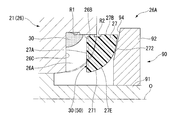
- FIG. 3 is an enlarged view of a main part of the impeller cover according to the first embodiment of the present invention, and is a cross-sectional view taken along line III-III in FIG. 2.
- FIG. 4 is an enlarged view of a main part of the impeller cover according to the first embodiment of the present invention, and is a cross-sectional view taken along line IV-IV in FIG. 2. It is a figure which shows the state before the assembly of the impeller cover which concerns on 1st embodiment of this invention.
- the turbocharger 1 (rotary machine) according to an embodiment of the present invention will be described.
- the turbocharger 1 includes a rotating shaft 2, a turbine 3 and a compressor 4 that rotate together with the rotating shaft 2, and a housing connecting portion 5 that connects the turbine 3 and the compressor 4 and supports the rotating shaft 2.
- the turbine 3 is rotated by exhaust gas G from an engine (not shown), and the air AR compressed by the compressor 4 along with the rotation is supplied to the engine.
- the rotating shaft 2 extends in the direction of the axis O and rotates around the axis O.
- the turbine 3 is disposed on one side in the direction of the axis O (on the right side as viewed in FIG. 1).
- the turbine 3 includes a turbine impeller 14 to which the rotary shaft 2 is attached and a turbine blade 15, and a turbine housing 11 that covers the turbine impeller 14 from the outer peripheral side.
- the turbine impeller 14 is fitted with the rotary shaft 2 and can rotate around the axis O together with the rotary shaft 2.
- the turbine housing 11 covers the turbine impeller 14.
- the turbine housing 11 is formed in an annular shape extending from the front edge portion (radially outer end portion) of the turbine blade 15 toward the radially outer side and centered on the axis O at the radially outer position.
- a scroll passage 12 communicating with the inside and outside of the housing 11 is formed.
- the turbine housing 11 is formed with an exhaust port 13 that opens on one side of the axis O, and the exhaust gas G that has passed through the turbine blade 15 circulates toward one side of the axis O, and the exhaust port 13. To the outside of the turbine housing 11.
- the compressor 4 is disposed on the other side in the direction of the axis O (left side as viewed in FIG. 1).
- a compressor impeller 24 (impeller 24) to which the rotary shaft 2 is attached and a compressor blade 25 (blade 25) is attached to the compressor 4, and a compressor housing 21 (impeller cover) that covers the compressor impeller 24 from the outer peripheral side. 21).
- the compressor impeller 24 has a disk-like disk that projects from the outer peripheral surface of the rotary shaft 2 to the outside in the radial direction of the axis O.
- the compressor impeller 24 has a radial shape about the axis O on the surface on one side of the disk in the axis O direction, and is arranged at intervals in the circumferential direction.
- the rotary shaft 2 is fitted in the compressor impeller 24 and can rotate around the axis O together with the rotary shaft 2.
- the compressor housing 21 covers the compressor impeller 24.
- the compressor housing 21 is formed with a suction port 23 that opens on the other side of the axis O, and the air AR is introduced into the compressor impeller 24 from the outside of the compressor housing 21 through the suction port 23.
- the compressor impeller 24 rotates around the axis O, and the air AR is compressed.
- the compressor housing 21 extends from the rear edge portion (downstream end portion of the flow of the air AR) of the compressor blade 25 toward the radially outer side, and has an annular shape centered on the axis O at the radially outer position.
- a compressor passage 22 is formed to communicate between the inside and outside of the compressor housing 21. The air AR compressed by the compressor impeller 24 is introduced into the compressor passage 22 and discharged to the outside of the compressor housing 21.
- the housing connecting portion 5 is disposed between the compressor housing 21 and the turbine housing 11 and connects them. Further, the housing connecting portion 5 covers the rotating shaft 2 from the outer peripheral side, and the housing connecting portion 5 is provided with a bearing 6 so that the rotating shaft 2 can be rotated relative to the housing connecting portion 5. I support it.
- the compressor housing 21 includes a housing main body (cover main body 26) constituting the outer shape of the compressor housing 21 and an abradable fixed to the housing main body.
- a seal portion 27 and a filler 30 interposed between the cover main body 26 and the abradable seal portion 27 are provided.
- the cover body 26 is formed with a seal accommodating portion 26A for accommodating the abradable seal portion 27 described above.
- 26 A of seal accommodating parts are substantially annular recessed parts formed in the inner peripheral side of the cover main body 26 seeing from the other side in the axis O direction.
- the inner peripheral surface of the seal housing portion 26A (that is, the surface on the outer side in the radial direction of the axis O) is a fitting inner peripheral surface 26B, and the surface on one side in the axis O direction is the axis of the abradable seal portion 27 described later.
- the reference surface 26C is used for positioning in the O direction.
- the fitting inner peripheral surface 26B extends substantially parallel to the axis O and has a substantially circular cross section when viewed from the direction of the axis O.
- the reference surface 26C is a substantially circular surface that spreads in a direction orthogonal to the axis O. Note that the reference surface 26C does not necessarily need to be completely orthogonal to the axis O, and a slight error or the like is allowed as long as it is substantially orthogonal.
- the surface located on the radially outer side of the seal housing portion 26A with respect to the axis O (that is, the surface on the outer peripheral side of the seal housing portion 26A) extends vertically in a plane generally orthogonal to the axis O. It is set as the surface 26D.
- the surface located on the radially inner side of the seal housing portion 26A (that is, the surface located on the radially inner side of the seal housing portion 26A) forms a part of the inner wall of the flow channel communicating with the suction port 23 described above. ing.
- a first groove R1 that is recessed toward the outside in the radial direction of the axis O is formed in a region on one side of the fitting inner peripheral surface 26B in the axis O direction.
- the first groove R1 extends in the circumferential direction of the axis O on the fitting inner peripheral surface 26B.
- the first groove R1 has a substantially rectangular cross section when viewed from the circumferential direction of the axis O.
- first hole portion H1 a plurality of holes (first hole portion H1) are formed on the reference surface 26C of the seal housing portion 26A. As shown in FIG. 3, a positioning pin 40 for inserting the circumferential position of the abradable seal portion 27 is inserted into the first hole H1.
- the abradable seal portion 27 is a member formed integrally with a fluororesin such as PTFE (polytetrafluoroethylene). As a result, the abradable seal portion 27 has a lower hardness than the material constituting the compressor blade 25. For example, when the tip portion (tip portion) of the blade 25 comes into contact with the abradable seal portion 27, the abradable seal portion 27 is cut by the tip portion. That is, the possibility that the tip portion is worn or bent is reduced.
- PTFE polytetrafluoroethylene
- the gap (clearance) between the abradable seal portion 27 and the tip portion of the blade 25 becomes extremely small through the above cutting.
- the abradable seal portion 27 seals leakage (fluid AR) and backflow between the blade 25 and the blade 25.
- the abradable seal portion 27 is generally formed in an annular shape by injection molding or cutting the resin material as described above (see FIG. 2). Further, the abradable seal portion 27 is bonded and fixed via the filler 30 in the seal housing portion 26A.
- the filler 30 is a liquid medicine capable of bonding the abradable seal portion 27, which is a resin, and the cover body 26 (metal material) to each other. As will be described in detail later, after such a filler 30 is filled between the seal housing portion 26A and the abradable seal portion 27 and then cured, the two are fixed to each other.
- the abradable seal portion 27 is fixed to the seal housing portion 26A (an assembled state). That is, in the assembled state, the central axis O of the abradable seal portion 27 is generally coaxial with the axis O of the cover body 26 (turbocharger 1). In such an assembled state, the surface facing the reference surface 26C of the seal housing portion 26A (that is, the end surface on the one side in the axis O direction) is substantially parallel to the reference surface 26C of the seal housing portion 26A. By being formed, the contact surface 27A is formed. Further, as shown in FIG. 2, the contact surface 27A is formed with a plurality of concave grooves (capturing portions 50) extending radially about the axis O.
- twelve concave grooves are formed at intervals in the circumferential direction of the axis O.
- the openings of these concave grooves are closed by the reference surface 26C, so that A gap is formed in.
- excess filler 30 is captured in the gap, and exudation to other regions is suppressed.
- the abradable seal portion 27 is formed with a plurality of (two) holes (second hole portion H2) that are recessed from the contact surface 27A toward the other side in the axis O direction.
- second hole portion H2 are provided at positions corresponding to the first hole portion H1 formed on the reference surface 26C of the seal housing portion 26A in the circumferential direction and the radial direction of the axis O, respectively.
- these 2nd hole parts H2 are formed in the area
- the first hole H1 (the hole on the seal housing portion 26A side) is also formed at a position corresponding to the second hole H2.
- a second groove portion R ⁇ b> 2 that is recessed inward in the radial direction is formed in a region on one side in the axis O direction on the outer peripheral surface of the abradable seal portion 27.
- the second groove R2 has a substantially rectangular cross section when viewed from the circumferential direction of the axis O.
- the dimension in the axis O direction of 2nd groove part R2 is set smaller than said 1st groove part R1. More specifically, when the abradable seal portion 27 is housed in the seal housing portion 26A, the second groove portion R2 as viewed from the radial direction of the axis O is in the direction of the axis O with respect to the first groove R1. It is formed at a position overlapping with the other side region.
- the inner wall surface on the other side in the axis O direction of the first groove R1 and the second groove R2 is flush with the axis O direction.
- a region extending to the other side in the axis O direction from the second groove portion R2 is formed as an inlay portion 27B by extending substantially parallel to the axis O direction.
- the radial dimension (outer diameter dimension) of the inlay portion 27B is substantially the same as the inner diameter dimension of the fitting inner peripheral surface 26B of the seal housing portion 26A. Thereby, the inlay part 27B contacts the fitting inner peripheral surface 26B substantially without a gap.
- a region (insertion portion 27C) extending on one side in the axis O direction from the second groove portion R2 on the outer peripheral surface of the abradable seal portion 27 has a slightly smaller radial dimension than the above-described spigot portion 27B. is doing.
- a slight gap is formed between the insertion portion 27C and the fitting inner peripheral surface 26B.
- an end portion on one side in the axis O direction of the insertion portion 27C is chamfered so as to be inclined with respect to the axis O, thereby forming a tapered surface 27D.
- the other surface (channel surface 27E) of the abradable seal portion 27 in the direction of the axis O is continuous with the shroud surface 271 formed in a curved shape as shown in FIGS. A connecting surface 272 to be connected.
- the shroud surface 271 forms a region on one side of the flow path surface 27E in the direction of the axis O, and is curved from the inner side in the radial direction toward the outer side in the radial direction as it goes from one side of the axis O to the other side.
- the shroud surface 271 faces the tip portion of the compressor blade 25 with a gap of about 0.1 mm in the state where it is incorporated in the cover main body 26. That is, the shroud surface 271 has a shape corresponding to the shape of the tip portion of the impeller 24 when viewed from the circumferential direction of the axis O.
- the broken line inside the shroud surface 271 represents the shroud reference surface Vs.
- the shroud reference surface Vs is a virtual surface that is flush with the vertical surface 26D of the cover body 26 and the inlet-side inner peripheral surface (the inner peripheral surface on one side in the axis O direction) of the cover main body 26.
- the shroud reference surface Vs extends along the tip portion of the blade 25 at a position separated by about 0.3 mm from the compressor blade 25. That is, the shroud surface 271 protrudes 0.2 mm from the shroud reference surface Vs toward the tip portion side.
- connection surface 272 located on the other side in the axis O direction with respect to the shroud surface 271 extends substantially linearly when viewed from the circumferential direction of the axis O. More specifically, the connection surface 272 is inclined so as to go from the inner side to the outer side in the radial direction as it goes from one side of the axis O to the other side.
- the radially outer end of the connection surface 272 is continuously connected to the vertical surface 26D (described above) of the cover body 26.
- the connection surface 272 and the vertical surface 26D are flush with each other so that there is substantially no step or displacement.
- the shape of the shroud surface 271 in the above-described flow path surface 27E is previously formed by cutting or polishing prior to the assembly of the abradable seal portion 27 with respect to the cover body 26.
- the abradable seal part 27 which concerns on this embodiment is the area
- the abradable seal portion 27 configured as described above is fixed in the seal housing portion 26A by the filler 30.
- a filler 30 for example, a silicon or acrylic adhesive is mainly used. These adhesives have a relatively high viscosity and a property of curing after a certain time. Further, those having a small volume shrinkage due to curing are particularly preferably used.
- the polytetrafluoroethylene forming the abradable seal portion 27 exhibits good machinability, but has a fluorine coating and therefore has poor affinity for the adhesive (filler 30) as described above. Therefore, by performing the defluorination treatment, the fluorine component in the extreme surface layer of the abradable seal portion 27 is removed, and the affinity with the adhesive (improving the bonding strength) is achieved.
- the filler 30 is filled in the region shown in FIG. 3 or FIG. As shown in FIG. 3, the filler 30 is filled in the first groove R1 of the seal housing portion 26A with almost no gap. Furthermore, the filler 30 is also filled in the second groove R2 of the abradable seal portion 27 with almost no gap. As a result, the cured filler 30 has a bowl shape inside the first groove R1 and the second groove R2.
- first cured portion 31 a portion (first cured portion 31) surrounded in the radial direction between the insertion portion 27C of the abradable seal portion 27 and the inner peripheral surface (bottom surface) of the second groove portion R2, and the first A portion (second hardened portion 32) surrounded by the radial direction between the bottom surfaces of the groove portion R1 and the second groove portion R2 is formed.
- the 2nd hardening part 32 will be in the state engaged with 2nd groove part R2 of the abradable seal part 27 from the radial direction outer side.
- the filler 30 is slightly interposed between the reference surface 26C of the seal housing portion 26A and the contact surface 27A of the abradable seal portion 27. As will be described in detail later, when the abradable seal portion 27 is press-fitted into the seal housing portion 26A, the filler 30 spreads thinly by the pressure applied between the contact surface 27A and the reference surface 26C, and after curing, Is in the form of a thin film and spreads in the radial direction of the axis O with almost no gap.
- FIG. 5 a pre-curing (liquid) filler 30 is applied in the seal housing portion 26A. More specifically, the filler 30 is applied substantially uniformly over the entire area in the circumferential direction to the corner formed by the fitting inner circumferential surface 26B (second groove portion R2) of the seal housing portion 26A and the reference surface 26C. To do. As described above, since the filler 30 has a relatively high viscosity, it does not flow immediately after application, and is held at the corners for a certain period of time.
- the abradable seal portion 27 in a state in which the shape processing of the flow path surface 27E (the shroud surface 271 and the connection surface 272) is completed is placed on the other side in the axis O direction of the cover body 26.
- a jig press-fit jig 90
- the press-fitting jig 90 includes a center pin 91 that extends in a columnar shape along a linear center axis, and a press-fit ring 92 that can slide in the center axis direction on the outer peripheral side of the center pin 91. ing.
- An end portion on one side in the central axis direction of the center pin 91 is formed as a flange portion 93 by expanding the diameter outward in the radial direction.
- the flange portion 93 is slightly smaller than the inner diameter dimension on one side of the cover main body 26 in the axis O direction, or has substantially the same outer diameter dimension.
- the press-fitting ring 92 has an annular plate shape that spreads radially outward from the central axis of the center pin 91.
- a taper portion 94 is formed on one surface (that is, the surface facing the cover main body 26 during assembly) of both surfaces in the central axial direction of the press-fitting ring 92.
- the taper portion 94 is inclined with respect to the radial direction of the central axis by extending from the other end side in the central axial direction toward the inner side in the radial direction from the radially outer end face of the press-fitting ring 92.
- the tapered portion 94 is formed so as to be substantially parallel to the connection surface 272 of the abradable seal portion 27 in a state where the press-fitting jig 90 is in contact with the abradable seal portion 27.
- a hole having an inner diameter that is substantially the same as the outer dimension of the center pin 91 is formed at the center of the press-fitting ring 92.
- the press-fit ring 92 When assembling, the press-fit ring 92 is moved toward one side in the direction of the axis O in a state where the taper portion 94 of the press-fit ring 92 is in contact with the connection surface 272 of the abradable seal portion 27.
- the double seal portion 27 is press-fitted into the seal housing portion 26A.
- the insertion portion 27C of the abradable seal portion 27 has an outer diameter dimension slightly smaller than the inner diameter dimension of the fitting inner peripheral surface 26B of the seal housing portion 26A, and the axis O A tapered portion 94 is formed on one side in the direction.
- the abradable seal portion 27 is moved to the axis O Inserted in one direction. Thereby, the contact surface 27A of the abradable seal portion 27 contacts the filler 30 applied to the corner portion of the seal housing portion 26A.
- the surplus portion of the filler 30 that does not fit in the first hardened portion 31 and the second hardened portion 32 is pushed out to one side in the axis O direction through the tapered portion 94 of the insertion portion 27C.
- Excess filler 30 extruded is spread along the reference surface 26 ⁇ / b> C on the contact surface 27 ⁇ / b> A side of the abradable seal portion 27.
- the filler 30 is interposed in a thin film between the contact surface 27A and the reference surface 26C.
- the filler 30 pushed out from between the contact surface 27A and the reference surface 26C is guided into the capturing part 50 (concave groove). Further, when surplus filler 30 is generated, the filler 30 slightly flows out radially inward from the capturing portion 50.
- the abradable seal portion 27 is fixed to the cover body 26 (in the seal housing portion 26A) after the filler 30 is cured.
- the abradable seal portion 27 when the abradable seal portion 27 is fixed to the seal housing portion 26 ⁇ / b> A, the excess filler 30 is used as the capturing portion 50 even when the excess filler 30 is applied. Therefore, the abradable seal portion 27 can be more accurately fixed to the reference surface 26C.
- the concave grooves as the capturing portions 50 are radially formed on at least a part of the contact surface 27A of the abradable seal portion 27.
- first groove portion R1 is formed on the fitting inner peripheral surface 26B of the seal housing portion 26A, and a second groove portion R2 facing the first groove portion R1 is formed on the outer peripheral surface of the abradable seal portion 27. Is formed.
- the filler 30 cured in the first groove R1 and the second groove R2 forms the first cured portion 31 and the second cured, respectively.
- the 2nd hardening part 32 engages from the axis O direction with respect to the side surface of the axis O direction one side of 2nd groove part R2.
- the abradable seal portion 27 has an axis line with respect to the seal housing portion 26A. The possibility of displacement in the O direction or dropping off can be reduced.
- the flow path surface 27E of the abradable seal portion 27 is a connection that continuously connects the radially outer end of the shroud surface 271 and the inner peripheral surface of the cover body 26.
- a surface 272 is formed.
- the abradable seal portion 27 and the inner peripheral surface of the cover body 26 are continuously connected by the connection surface 272, when the impeller cover 21 is used for the turbocharger 1.
- the generation of vortices in the vicinity of the connection surface 272 can be reduced, and the surge flow rate of the fluid can be reduced.
- the abradable seal part 27 is formed of a resin material obtained by defluorinating a fluororesin, the affinity of the abradable seal part 27 for the filler 30 can be improved. That is, the abradable seal portion 27 can be fixed sufficiently firmly to the impeller cover 21 (cover body 26).
- the abradable seal portion 27 is configured to cover a region of 1/3 or more from one side in the axis O direction among the dimensions of the compressor blade 25 in the meridian direction.
- the manufacturing method of the impeller cover 21 described above includes a step of forming the shroud surface 271 by processing the abradable seal portion 27, a step of applying the filler 30 to the seal housing portion 26A, A step of fitting the abradable seal portion 27 to the seal housing portion 26A in a state where the filler 30 is interposed, and a step of press-fitting the abradable seal portion 27 from the other side in the axis O direction. (FIG. 10).
- the shroud surface 271 is processed prior to fitting and press-fitting the abradable seal portion 27 into the seal housing portion 26A.
- the impeller cover 21 can be assembled more easily than when the shroud surface 271 is processed with the abradable seal portion 27 assembled to the cover body 26.
- the abradable seal portion 27 is inserted into a first hole H1 formed on the seal housing portion 26A side and a second hole H2 formed in the abradable seal portion 27 itself.
- the positioning pin 40 restricts the displacement of the axis O in the circumferential direction.
- the abradable seal portion 27 is gradually cut while the compressor impeller 24 is rotated forward of the rotation direction. It is assumed that an external force is applied toward the side. According to the above configuration, even when such an external force in the circumferential direction is applied, the positioning pin 40 is provided so that the displacement in the circumferential direction (that is, the rotation of the abradable seal portion 27) is achieved. ) Can be regulated.
- the configuration of the capturing unit 50 is not limited to the above, and other configurations such as those illustrated in FIGS. 6 and 7 may be employed.
- a concave groove is formed in a partial region on the radially outer side in the contact surface 27 ⁇ / b> A of the abradable seal portion 27.
- the abradable seal portion 27 in the assembled state stays in the concave groove on the radially outer side of the contact surface 27A. In other words, even when surplus filler 30 is generated, the possibility of the filler 30 leaching from the contact surface 27A toward the radially inner side of the abradable seal portion 27 can be reduced. .
- the abradable seal portion 27 in FIG. 8 is formed on the radially inner side of the concave groove in addition to the concave groove as the capturing portion 50 formed on a part of the contact surface 27A (a region on the radially outer side). And a protruding portion 27F. Further, a recessed portion 26E having a shape corresponding to the protruding portion 27F is formed in a radially inner region on the reference surface 26C of the seal housing portion 26A.
- the protruding portion 27F is fitted to the recessed portion 26E, so that the radially inner end of the capturing portion 50 (concave groove) is closed by the protruding portion 27F. . Therefore, it is possible to further reduce the possibility that excess filler 30 oozes out radially inward.
- the positioning accuracy of the abradable seal portion 27 in the radial direction can be further improved by the protruding portion 27F formed on the contact surface 27A.
- At least one air vent groove 28 extending in the direction of the axis O may be formed on the spigot portion 27B of the abradable seal portion 27 of FIG. More specifically, the air vent groove 28 is a linear concave groove extending from the first groove portion R1 toward the other side in the axis O direction. Further, the other end of the air vent groove 28 in the direction of the axis O communicates with the outside. With such a configuration, when the abradable seal portion 27 is inserted into the seal housing portion 26A, the air interposed in the capturing portion 50 (concave groove) 50, the first groove portion R1, and the second groove portion R2 becomes the air. Since it is discharged to the outside through the extraction groove 28, the force required for press-fitting the abradable seal portion is reduced, and workability can be improved.
- the abradable seal portion 27 covers at least a part of the dimension in the meridian direction of the compressor blade 25 in the state of being accommodated in the seal accommodating portion 26A. It is configured (see FIG. 3). Further, the connecting portion of the abradable seal portion 27 extends further radially outward than the outlet side (radially outer end portion) of the compressor blade 25.
- the various characteristic values of the compressor 4 were evaluated using a plurality of models in which the position where the abradable seal portion 27 was arranged was different. Specifically, as shown in Table 1 above, the peak efficiency (maximum compression efficiency) under the rated rotational speed (rated flow rate) in a plurality of models with different arrangements of the abradable seal portions 27 and The compression efficiency (small flow rate efficiency) and the choke flow ratio under a rotational speed (small rotational speed) lower than the rated value were measured.
- the rotational speed of the compressor 4 when measuring the peak efficiency was 178000 rpm, and the rotational speed of the compressor 4 when measuring the small flow efficiency was 133,000 rpm.
- the clearance between the tip portion of the compressor impeller 24 and the shroud surface 271 of the abradable seal portion 27 and the position (m) of the shroud surface 271 with respect to the meridian length of the compressor blade 25 are respectively determined. Measurement tests were performed on four different cases. M in Table 1 indicates the relative position of the compressor blade 25 in the meridian direction, the end (inlet) on one side in the axis O direction is represented by 0, and the end (outlet) on the other side in the axis O direction is represented by 1. To express.
- the shroud surface 271 represents a state in which the shroud surface 271 is separated from the tip side of the compressor blade 25 by 0.3 mm over the entire meridian length.
- Case 0 mimics a configuration that does not include the abradable seal portion 27.
- the value of m is different. That is, the separation dimension between the shroud surface 271 and the tip part is partially different over the meridian length of the compressor blade 25.
- Case 1 with respect to the meridian length, the separation dimension is set to 0.1 mm in the region of 0.67 to 1 with reference to the inlet side end of the compressor blade 25. That is, Case 1 simulates a configuration in which the abradable seal portion 27 is unevenly distributed on the outlet side of the compressor blade 25.
- Case 2 has a separation dimension of 0.1 mm in the region from 0.33 to 0.67 with respect to the meridian length, with the inlet side end of the compressor blade 25 as a reference. That is, Case 2 imitates a configuration in which the abradable seal portion 27 is unevenly distributed in an intermediate portion (a central region in the meridian length) of the compressor blade 25.
- Case 3 has a separation dimension of 0.1 mm in an area of 0 to 0.33 with reference to the inlet side end of the compressor blade 25. That is, Case 3 simulates a configuration in which the abradable seal portion 27 is unevenly distributed on the inlet side of the compressor blade 25.
- Table 1 shows the percentage increase / decrease of each measurement result (peak efficiency, small flow efficiency, choke flow) of Case 1 to Case 3 with respect to Case 0 in the above Case 0 to Case 3 configuration.
- Case 1 showed an increase rate of 1.3%
- Case 2 an increase rate of 2.4%
- Case 3 an increase rate of 3.2%.
- Case 3 shows an increase rate of 0.6% with respect to Case 0. Therefore, it can be seen that effective results were obtained compared to Cases 1 and 2.
- the choke flow rate ratio is a percentage change in the choke flow rate under the conditions of Case 1 to Case 3 with reference to the flow rate (choke flow rate) at the time when choke is generated in the Case 0 configuration. That is, it can be seen from the results in Table 1 that the choke flow rate in Case 3 was reduced by 3% with respect to Case 0.
- the manufacturing method of the impeller cover 21, the rotating machine, and the impeller cover 21 described above can be applied to, for example, the compressor 4 of a supercharger. Thereby, a rotating machine having sufficient efficiency can be easily manufactured.
Landscapes
- Engineering & Computer Science (AREA)
- General Engineering & Computer Science (AREA)
- Mechanical Engineering (AREA)
- Chemical & Material Sciences (AREA)
- Combustion & Propulsion (AREA)
- Structures Of Non-Positive Displacement Pumps (AREA)
- Supercharger (AREA)
Abstract
Description
本発明の第一の態様によれば、インペラカバーは、軸線回りに回転するインペラの外周面に対向するシュラウド面を有し、前記外周面と前記シュラウド面との間をシールする被削性のアブレイダブルシール部と、前記インペラを外側から覆うとともに、前記アブレイダブルシール部が収容されるシール収容部を有するカバー本体と、前記アブレイダブルシール部と前記カバー本体との間に介在する充填材と、を備え、前記シール収容部は、軸線に沿って延びることで前記アブレイダブルシール部の外周面が嵌合される嵌合内周面と、前記アブレイダブルシール部に軸線方向一方側から当接することで該アブレイダブルシール部の軸線方向における位置決めをする基準面と、を有し、前記アブレイダブルシール部と前記シール収容部との間の少なくとも一部に隙間を形成することで、余剰な前記充填材を捕捉する捕捉部を有する。 The present invention employs the following means in order to solve the above problems.
According to the first aspect of the present invention, the impeller cover has a shroud surface facing the outer peripheral surface of the impeller that rotates about the axis, and has a machinability that seals between the outer peripheral surface and the shroud surface. An abradable seal part, a cover body that covers the impeller from the outside and has a seal housing part for housing the abradable seal part, and is interposed between the abradable seal part and the cover body A sealing material, and the seal housing portion extends along an axial line so that the outer peripheral surface of the abradable seal portion is fitted to the fitting inner peripheral surface, and the abradable seal portion is axially oriented. A reference surface for positioning the abradable seal portion in the axial direction by abutting from one side, and a small gap between the abradable seal portion and the seal housing portion. Ku and also by forming a gap portion comprises a capturing part that captures excess the filler.
特に、カバー本体に組み付けられた状態のアブレイダブルシール部に切削加工を施す場合、工具のアクセス可能な範囲が限定的となることから、十分な加工精度が得られない可能性がある。しかしながら、上述の方法によればこのような可能性を低減することができる。 According to the above method, the shroud surface is processed prior to fitting and press-fitting the abradable seal portion into the seal housing portion. In other words, the impeller cover can be assembled more easily than when the shroud surface is processed with the abradable seal portion assembled to the cover body.
In particular, when cutting is performed on the abradable seal portion assembled in the cover main body, the accessible range of the tool is limited, and thus sufficient processing accuracy may not be obtained. However, according to the method described above, such a possibility can be reduced.
本発明の第一実施形態について、図面を参照して説明する。
以下、本発明の実施形態に係るターボチャージャ1(回転機械)について説明する。
図1に示すようにターボチャージャ1は、回転軸2と、回転軸2とともに回転するタービン3及び圧縮機4と、タービン3と圧縮機4を連結するとともに回転軸2を支持するハウジング連結部5と、を備えている。
このターボチャージャ1では、図示しないエンジンからの排気ガスGによりタービン3が回転し、当該回転に伴って圧縮機4が圧縮した空気ARをエンジンに供給する。 [First embodiment]
A first embodiment of the present invention will be described with reference to the drawings.
Hereinafter, a turbocharger 1 (rotary machine) according to an embodiment of the present invention will be described.
As shown in FIG. 1, the
In the
このタービン3は、回転軸2が取付けられるとともにタービンブレード15を有するタービンインペラ14と、タービンインペラ14を外周側から覆うタービンハウジング11とを備えている。 The rotating shaft 2 extends in the direction of the axis O and rotates around the axis O. The
The
この圧縮機4には、回転軸2が取付けられるとともに圧縮機ブレード25(ブレード25)を有する圧縮機インペラ24(インペラ24)と、圧縮機インペラ24を外周側から覆う圧縮機ハウジング21(インペラカバー21)とを備えている。より詳細には、この圧縮機インペラ24は、回転軸2の外周面から軸線Oの径方向外側に張り出す円盤状のディスクを有している。圧縮機インペラ24は、このディスクにおける軸線O方向一方側の面上で、軸線Oを中心として放射状をなすとともに、周方向に間隔をあけて配列されている。さらに、圧縮機インペラ24には、回転軸2が嵌り込んでおり、回転軸2とともに軸線O回りに回転可能となっている。 The compressor 4 is disposed on the other side in the direction of the axis O (left side as viewed in FIG. 1).
A compressor impeller 24 (impeller 24) to which the rotary shaft 2 is attached and a compressor blade 25 (blade 25) is attached to the compressor 4, and a compressor housing 21 (impeller cover) that covers the
さらに、図2に示すように、この当接面27Aには、軸線Oを中心として放射状に延びる複数の凹溝(捕捉部50)が形成されている。より具体的には、図2の例では軸線Oの周方向に間隔を空けて、12個の凹溝(捕捉部50)が形成されている。アブレイダブルシール部27がシール収容部26Aに収容されたときに、これら凹溝の開口(軸線O方向一方側の開口)は、基準面26Cによって閉塞されることで、基準面26Cとの間には隙間が形成される。詳しくは後述するが、この隙間が設けられていることで、余剰な充填材30が該隙間に捕捉され、他の領域への滲出が抑制される。 3 or 4 shows a state where the
Further, as shown in FIG. 2, the

Claims (8)
- 軸線回りに回転するインペラの外周面に対向するシュラウド面を有し、前記外周面と前記シュラウド面との間をシールする被削性のアブレイダブルシール部と、
前記インペラを外側から覆うとともに、前記アブレイダブルシール部が収容されるシール収容部を有するカバー本体と、
前記アブレイダブルシール部と前記カバー本体との間に介在する充填材と、
を備え、
前記シール収容部は、軸線に沿って延びることで前記アブレイダブルシール部の外周面が嵌合される嵌合内周面と、前記アブレイダブルシール部に軸線方向一方側から当接することで該アブレイダブルシール部の軸線方向における位置決めをする基準面と、を有し、
前記アブレイダブルシール部と前記シール収容部との間の少なくとも一部に隙間を形成することで、余剰な前記充填材を捕捉する捕捉部を有するインペラカバー。 An abradable seal portion having a shroud surface facing an outer peripheral surface of an impeller rotating around an axis, and sealing between the outer peripheral surface and the shroud surface;
A cover body having a seal housing portion that covers the impeller from the outside and that houses the abradable seal portion;
A filler interposed between the abradable seal portion and the cover body;
With
The seal housing portion extends along the axis so that the outer peripheral surface of the abradable seal portion is fitted to the fitting inner peripheral surface and the abradable seal portion is brought into contact with the abradable seal portion from one side in the axial direction. A reference surface for positioning in the axial direction of the abradable seal portion,
An impeller cover having a capturing portion that captures excess filler by forming a gap in at least a portion between the abradable seal portion and the seal housing portion. - 前記捕捉部は、前記アブレイダブルシール部の軸線方向一方側の端面の少なくとも一部に形成され、軸線を中心として放射状に延びる凹溝である請求項1に記載のインペラカバー。 2. The impeller cover according to claim 1, wherein the capturing part is a concave groove that is formed on at least a part of an end face on one side in the axial direction of the abradable seal part and extends radially about the axis.
- 前記嵌合内周面には、径方向外側に凹没するとともに、周方向に延びる第一溝部が形成され、
前記アブレイダブルシール部の外周面には、前記第一溝部と対向する領域で周方向に延びるとともに、前記第一溝部よりも大きい軸線方向寸法を有する第二溝部が形成されている
請求項1又は2に記載のインペラカバー。 The fitting inner peripheral surface is recessed with a radially outer side and a first groove portion extending in the circumferential direction is formed,
2. A second groove portion extending in a circumferential direction in a region facing the first groove portion and having a larger axial dimension than the first groove portion is formed on an outer peripheral surface of the abradable seal portion. Or the impeller cover of 2. - 前記アブレイダブルシール部は、前記シュラウド面における径方向外側の端部と、前記カバー本体の内周面との間を連続的に接続する接続面を有する請求項1から3のいずれか一項に記載のインペラカバー。 The said abradable seal part has a connection surface which connects continuously between the edge part of the radial direction outer side in the said shroud surface, and the internal peripheral surface of the said cover main body. Impeller cover as described in.
- 前記アブレイダブルシール部は、フッ素樹脂を脱フッ素化処理した樹脂材料で形成される請求項1から4のいずれか一項に記載のインペラカバー。 The impeller cover according to any one of claims 1 to 4, wherein the abradable seal part is formed of a resin material obtained by defluorinating a fluororesin.
- 軸線に沿って延びる回転軸と、
前記回転軸に固定された径方向外側に張り出すディスク、及び該ディスクの軸線方向一方側を向く面に周方向に間隔をあけて複数設けられて、軸線方向一方側から径方向外側に延びる流路を形成するブレードを有するインペラと、
請求項1から5のいずれか一項に記載のインペラカバーと、
を備える回転機械。 A rotation axis extending along the axis;
A disk extending radially outwardly fixed to the rotating shaft, and a plurality of circumferentially spaced surfaces extending from the axially one side to the radially outward side of the disk. An impeller having blades forming a path;
An impeller cover according to any one of claims 1 to 5;
Rotating machine with - 前記アブレイダブルシール部は、前記ブレードの子午線方向における寸法のうち、軸線方向一方側から1/3以上の領域を覆う請求項6に記載の回転機械。 The rotating machine according to claim 6, wherein the abradable seal portion covers a region of 1/3 or more from one side in the axial direction among dimensions of the blade in the meridian direction.
- 請求項1から6のいずれか一項に記載のインペラカバーの製造方法であって、
前記アブレイダブルシール部を加工することで前記シュラウド面を形成する工程と、
前記シール収容部に前記充填材を塗布する工程と、
前記充填材が介在した状態で前記アブレイダブルシール部を前記シール収容部に嵌合する工程と、
前記アブレイダブルシール部を軸線方向他方側から圧入する工程と、
を含むインペラカバーの製造方法。 A method for manufacturing an impeller cover according to any one of claims 1 to 6,
Forming the shroud surface by processing the abradable seal portion;
Applying the filler to the seal housing portion;
Fitting the abradable seal portion to the seal housing portion with the filler interposed therebetween;
Press-fitting the abradable seal portion from the other side in the axial direction; and
Of manufacturing an impeller cover.
Priority Applications (5)
| Application Number | Priority Date | Filing Date | Title |
|---|---|---|---|
| US15/555,683 US10683870B2 (en) | 2015-03-24 | 2015-03-24 | Impeller cover, rotary machine, and impeller cover manufacturing method |
| EP15886300.1A EP3276142B1 (en) | 2015-03-24 | 2015-03-24 | Impeller cover, rotary machine, and impeller cover manufacturing method |
| JP2017507203A JP6565124B2 (en) | 2015-03-24 | 2015-03-24 | Impeller cover, rotating machine, and method of manufacturing impeller cover |
| CN201580076981.0A CN107250507B (en) | 2015-03-24 | 2015-03-24 | The manufacturing method of impeller cover, rotating machinery and impeller cover |
| PCT/JP2015/058854 WO2016151747A1 (en) | 2015-03-24 | 2015-03-24 | Impeller cover, rotary machine, and impeller cover manufacturing method |
Applications Claiming Priority (1)
| Application Number | Priority Date | Filing Date | Title |
|---|---|---|---|
| PCT/JP2015/058854 WO2016151747A1 (en) | 2015-03-24 | 2015-03-24 | Impeller cover, rotary machine, and impeller cover manufacturing method |
Publications (1)
| Publication Number | Publication Date |
|---|---|
| WO2016151747A1 true WO2016151747A1 (en) | 2016-09-29 |
Family
ID=56977177
Family Applications (1)
| Application Number | Title | Priority Date | Filing Date |
|---|---|---|---|
| PCT/JP2015/058854 WO2016151747A1 (en) | 2015-03-24 | 2015-03-24 | Impeller cover, rotary machine, and impeller cover manufacturing method |
Country Status (5)
| Country | Link |
|---|---|
| US (1) | US10683870B2 (en) |
| EP (1) | EP3276142B1 (en) |
| JP (1) | JP6565124B2 (en) |
| CN (1) | CN107250507B (en) |
| WO (1) | WO2016151747A1 (en) |
Cited By (5)
| Publication number | Priority date | Publication date | Assignee | Title |
|---|---|---|---|---|
| JP2018096267A (en) * | 2016-12-12 | 2018-06-21 | 三菱重工エンジン&ターボチャージャ株式会社 | Turbocharger |
| JP6373502B1 (en) * | 2017-05-30 | 2018-08-15 | Tpr株式会社 | Method for manufacturing compressor housing for supercharger and compressor housing for supercharger |
| US20190041061A1 (en) * | 2016-02-16 | 2019-02-07 | Mitsubishi Heavy Industries, Ltd. | Joined structure, combustor, and combustion device |
| KR200492101Y1 (en) * | 2019-09-09 | 2020-08-06 | 변석준 | Blower with maximized wind pressure efficiency |
| KR200492899Y1 (en) * | 2019-09-09 | 2020-12-30 | 변석준 | Blower have a bearing cover for maximum cooling efficiency |
Families Citing this family (4)
| Publication number | Priority date | Publication date | Assignee | Title |
|---|---|---|---|---|
| JP6589217B2 (en) * | 2015-04-17 | 2019-10-16 | 三菱重工コンプレッサ株式会社 | Rotating machine, method of manufacturing rotating machine |
| EP3760851B1 (en) * | 2018-08-07 | 2023-05-03 | Mitsubishi Heavy Industries Engine & Turbocharger, Ltd. | Turbocharger and method for manufacturing a turbocharger |
| JP6867421B2 (en) * | 2019-01-23 | 2021-04-28 | ファナック株式会社 | Robot seal structure and robot |
| JP2022546968A (en) * | 2019-09-06 | 2022-11-10 | ジェイティー インターナショナル エス.エイ. | thin film heater |
Citations (5)
| Publication number | Priority date | Publication date | Assignee | Title |
|---|---|---|---|---|
| JP2005298042A (en) * | 2004-04-15 | 2005-10-27 | Sharp Kagaku Kogyo Kk | Highly viscous fluid container |
| JP2013211337A (en) * | 2012-03-30 | 2013-10-10 | Kyocera Corp | Heat sink |
| JP5364834B1 (en) * | 2012-10-10 | 2013-12-11 | 株式会社ホンダアクセス | Decorative parts for vehicles |
| JP5533060B2 (en) * | 2010-03-12 | 2014-06-25 | 株式会社Ihi | Turbocharger |
| JP5664785B2 (en) * | 2011-07-25 | 2015-02-04 | トヨタ自動車株式会社 | Compressor housing and exhaust turbine supercharger |
Family Cites Families (17)
| Publication number | Priority date | Publication date | Assignee | Title |
|---|---|---|---|---|
| JPS60156420A (en) | 1984-01-26 | 1985-08-16 | 松下電器産業株式会社 | Controller of electric pressure kettle |
| JP3639846B2 (en) | 1997-04-22 | 2005-04-20 | 株式会社協立 | Turbocharger with sliding member |
| JP2004325569A (en) * | 2003-04-22 | 2004-11-18 | Nec Tokin Corp | Receptacle and optical semiconductor element packaging module using the same |
| JP2004324569A (en) * | 2003-04-25 | 2004-11-18 | Ishikawajima Harima Heavy Ind Co Ltd | Supercharger and its manufacturing method |
| JP2008174791A (en) | 2007-01-18 | 2008-07-31 | Plasma Ion Assist Co Ltd | Adhesive surface modification method for fluorine base synthetic resin, and article obtained thereby |
| JP2011052558A (en) * | 2009-08-31 | 2011-03-17 | Toyota Motor Corp | Supercharger |
| JP2011163239A (en) | 2010-02-10 | 2011-08-25 | Toyota Motor Corp | Compressor housing for supercharger |
| WO2012158724A1 (en) * | 2011-05-16 | 2012-11-22 | Seaboard International Inc. | Valve seat and valve |
| JP2014047714A (en) | 2012-08-31 | 2014-03-17 | Toyota Motor Corp | Turbocharger |
| JP5928271B2 (en) | 2012-09-18 | 2016-06-01 | トヨタ自動車株式会社 | Compressor housing for supercharger and method for manufacturing the same |
| JP2014058918A (en) | 2012-09-18 | 2014-04-03 | Otics Corp | Compressor housing for supercharger |
| JP6092562B2 (en) | 2012-10-02 | 2017-03-08 | 株式会社オティックス | Compressor housing for supercharger and method for manufacturing the same |
| JP2014088785A (en) | 2012-10-29 | 2014-05-15 | Otics Corp | Compressor housing for supercharger |
| JP2014152614A (en) | 2013-02-05 | 2014-08-25 | Otics Corp | Compressor housing for supercharger |
| US20180283394A1 (en) | 2015-02-25 | 2018-10-04 | Otics Corporation | Compressor housing for turbocharger |
| JPWO2016136681A1 (en) * | 2015-02-25 | 2017-11-30 | 株式会社オティックス | Compressor housing for supercharger and method for manufacturing the same |
| JP2017082666A (en) * | 2015-10-27 | 2017-05-18 | 株式会社オティックス | Supercharger compressor housing and manufacturing method for the same |
-
2015
- 2015-03-24 US US15/555,683 patent/US10683870B2/en active Active
- 2015-03-24 JP JP2017507203A patent/JP6565124B2/en active Active
- 2015-03-24 EP EP15886300.1A patent/EP3276142B1/en active Active
- 2015-03-24 CN CN201580076981.0A patent/CN107250507B/en active Active
- 2015-03-24 WO PCT/JP2015/058854 patent/WO2016151747A1/en active Application Filing
Patent Citations (5)
| Publication number | Priority date | Publication date | Assignee | Title |
|---|---|---|---|---|
| JP2005298042A (en) * | 2004-04-15 | 2005-10-27 | Sharp Kagaku Kogyo Kk | Highly viscous fluid container |
| JP5533060B2 (en) * | 2010-03-12 | 2014-06-25 | 株式会社Ihi | Turbocharger |
| JP5664785B2 (en) * | 2011-07-25 | 2015-02-04 | トヨタ自動車株式会社 | Compressor housing and exhaust turbine supercharger |
| JP2013211337A (en) * | 2012-03-30 | 2013-10-10 | Kyocera Corp | Heat sink |
| JP5364834B1 (en) * | 2012-10-10 | 2013-12-11 | 株式会社ホンダアクセス | Decorative parts for vehicles |
Non-Patent Citations (1)
| Title |
|---|
| See also references of EP3276142A4 * |
Cited By (10)
| Publication number | Priority date | Publication date | Assignee | Title |
|---|---|---|---|---|
| US20190041061A1 (en) * | 2016-02-16 | 2019-02-07 | Mitsubishi Heavy Industries, Ltd. | Joined structure, combustor, and combustion device |
| JP2018096267A (en) * | 2016-12-12 | 2018-06-21 | 三菱重工エンジン&ターボチャージャ株式会社 | Turbocharger |
| WO2018110032A1 (en) * | 2016-12-12 | 2018-06-21 | 三菱重工エンジン&ターボチャージャ株式会社 | Turbocharger |
| CN109477420A (en) * | 2016-12-12 | 2019-03-15 | 三菱重工发动机和增压器株式会社 | Turbocharger |
| US10954816B2 (en) | 2016-12-12 | 2021-03-23 | Mitsubishi Heavy Industries Engine & Turbocharger, Ltd. | Turbocharger |
| JP6373502B1 (en) * | 2017-05-30 | 2018-08-15 | Tpr株式会社 | Method for manufacturing compressor housing for supercharger and compressor housing for supercharger |
| WO2018220713A1 (en) * | 2017-05-30 | 2018-12-06 | Tpr株式会社 | Method for manufacturing supercharger compressor housing, and supercharger compressor housing |
| EP3584424A4 (en) * | 2017-05-30 | 2020-01-15 | Tpr Co., Ltd. | Method for manufacturing supercharger compressor housing, and supercharger compressor housing |
| KR200492101Y1 (en) * | 2019-09-09 | 2020-08-06 | 변석준 | Blower with maximized wind pressure efficiency |
| KR200492899Y1 (en) * | 2019-09-09 | 2020-12-30 | 변석준 | Blower have a bearing cover for maximum cooling efficiency |
Also Published As
| Publication number | Publication date |
|---|---|
| EP3276142A1 (en) | 2018-01-31 |
| US10683870B2 (en) | 2020-06-16 |
| JPWO2016151747A1 (en) | 2017-12-14 |
| US20180045211A1 (en) | 2018-02-15 |
| CN107250507B (en) | 2019-08-30 |
| CN107250507A (en) | 2017-10-13 |
| JP6565124B2 (en) | 2019-08-28 |
| EP3276142A4 (en) | 2018-12-19 |
| EP3276142B1 (en) | 2020-10-07 |
Similar Documents
| Publication | Publication Date | Title |
|---|---|---|
| JP6565124B2 (en) | Impeller cover, rotating machine, and method of manufacturing impeller cover | |
| US10094391B2 (en) | Compressor housing for supercharger | |
| US9410443B2 (en) | Variable vane damping assembly | |
| JP2018145831A (en) | Turbocharger housing and its process of manufacture | |
| WO1999058857A1 (en) | Electric blower and vacuum cleaner using it | |
| CN107013492B (en) | Compressor housing for air cycle machine | |
| JP6177421B2 (en) | Seal structure and supercharger provided with the seal structure | |
| CN207145228U (en) | Compressor | |
| WO2015066301A1 (en) | Noise attenuation device for compressor inlet duct | |
| CN102537352B (en) | Air cycle machine seal land | |
| JP2018184928A (en) | Housing for turbo charger and manufacturing method therefor | |
| US10527051B2 (en) | Rotary machine and method for manufacturing rotary machine | |
| JP5088493B2 (en) | Seal structure and turbocharger | |
| US10047608B2 (en) | Balancing apparatus, arrangement and method | |
| CN105275883B (en) | The manufacturing method of compressor and compressor | |
| US11486411B2 (en) | Seal assembly | |
| CN111379744B (en) | Centrifugal rotary machine | |
| JP6597780B2 (en) | Seal structure and turbocharger | |
| JP5533060B2 (en) | Turbocharger | |
| RU2425270C1 (en) | Radial end contact seal of support of turbomachine | |
| CN204402646U (en) | Compressor end sealing structure of turbosuperchargers | |
| JP2019078215A (en) | Housing for turbo charger and manufacturing method thereof | |
| CN112074665B (en) | Centrifugal compressor | |
| JP2020172921A (en) | Compressor housing for turbocharger and manufacturing method thereof | |
| KR102010337B1 (en) | A housing for compressing apparatus and compressing apparatus |
Legal Events
| Date | Code | Title | Description |
|---|---|---|---|
| 121 | Ep: the epo has been informed by wipo that ep was designated in this application |
Ref document number: 15886300 Country of ref document: EP Kind code of ref document: A1 |
|
| ENP | Entry into the national phase |
Ref document number: 2017507203 Country of ref document: JP Kind code of ref document: A |
|
| WWE | Wipo information: entry into national phase |
Ref document number: 15555683 Country of ref document: US |
|
| REEP | Request for entry into the european phase |
Ref document number: 2015886300 Country of ref document: EP |
|
| NENP | Non-entry into the national phase |
Ref country code: DE |