JP2005298042A - Highly viscous fluid container - Google Patents
Highly viscous fluid container Download PDFInfo
- Publication number
- JP2005298042A JP2005298042A JP2004120214A JP2004120214A JP2005298042A JP 2005298042 A JP2005298042 A JP 2005298042A JP 2004120214 A JP2004120214 A JP 2004120214A JP 2004120214 A JP2004120214 A JP 2004120214A JP 2005298042 A JP2005298042 A JP 2005298042A
- Authority
- JP
- Japan
- Prior art keywords
- pouch
- container
- extrusion port
- flange portion
- extrusion
- Prior art date
- Legal status (The legal status is an assumption and is not a legal conclusion. Google has not performed a legal analysis and makes no representation as to the accuracy of the status listed.)
- Pending
Links
- 239000012530 fluid Substances 0.000 title claims abstract description 18
- 239000012790 adhesive layer Substances 0.000 claims abstract description 32
- 239000000758 substrate Substances 0.000 claims abstract description 30
- 230000001070 adhesive effect Effects 0.000 claims abstract description 15
- 239000000853 adhesive Substances 0.000 claims abstract description 14
- 230000002093 peripheral effect Effects 0.000 claims abstract description 12
- 239000000463 material Substances 0.000 claims abstract description 11
- 238000000034 method Methods 0.000 claims abstract description 11
- 238000001125 extrusion Methods 0.000 claims description 93
- 229920005989 resin Polymers 0.000 description 22
- 239000011347 resin Substances 0.000 description 22
- 239000010410 layer Substances 0.000 description 9
- 239000004743 Polypropylene Substances 0.000 description 5
- 238000001746 injection moulding Methods 0.000 description 5
- -1 polypropylene Polymers 0.000 description 5
- 229920001155 polypropylene Polymers 0.000 description 5
- 230000004888 barrier function Effects 0.000 description 4
- 230000000694 effects Effects 0.000 description 4
- BZHJMEDXRYGGRV-UHFFFAOYSA-N Vinyl chloride Chemical compound ClC=C BZHJMEDXRYGGRV-UHFFFAOYSA-N 0.000 description 3
- 229920000122 acrylonitrile butadiene styrene Polymers 0.000 description 3
- 229920006122 polyamide resin Polymers 0.000 description 3
- 229920013716 polyethylene resin Polymers 0.000 description 3
- 239000003566 sealing material Substances 0.000 description 3
- 230000002950 deficient Effects 0.000 description 2
- 229920001684 low density polyethylene Polymers 0.000 description 2
- 239000004702 low-density polyethylene Substances 0.000 description 2
- 238000000465 moulding Methods 0.000 description 2
- XAGFODPZIPBFFR-UHFFFAOYSA-N aluminium Chemical compound [Al] XAGFODPZIPBFFR-UHFFFAOYSA-N 0.000 description 1
- 229910052782 aluminium Inorganic materials 0.000 description 1
- 239000011888 foil Substances 0.000 description 1
- 238000010030 laminating Methods 0.000 description 1
- XLYOFNOQVPJJNP-UHFFFAOYSA-N water Chemical compound O XLYOFNOQVPJJNP-UHFFFAOYSA-N 0.000 description 1
Images

Landscapes
- Closures For Containers (AREA)
- Containers And Packaging Bodies Having A Special Means To Remove Contents (AREA)
- Bag Frames (AREA)
Abstract
Description
本発明は、例えば各種シーリング材をはじめとする接着剤等の高粘性流体を収容する容器および、該容器の組立方法に関する。 The present invention relates to a container for containing a highly viscous fluid such as an adhesive including various sealing materials, and a method for assembling the container.
現在、接着剤等の高粘性流体を収容する容器としては、特開平2001−335081に開示されている高粘性流体用容器等がある。 Currently, examples of containers that contain high-viscosity fluids such as adhesives include containers for high-viscosity fluids disclosed in JP-A-2001-335081.
前記高粘性流体用容器15は、フィルム状材料を袋状に形成してなるパウチ16と、該パウチ16の一端部に取り付けられる押出口とからなり、該押出口は、外周面に雄ねじが成形された筒状部12の一端に該パウチ16に対して貼着されるフランジ部13が形成されてなる押出口基体10と、コーン状の筒体の基端内周面に該雄ねじに螺合する雌ねじが形成された押出ノズル11によって構成されている。
The high-
前記押出口基体10は、前記パウチ16に貼着され、押出口として用いられるが、貼着の際、前記押出口基体10のフランジ部13の前記パウチ16に貼着される面に接着剤層14が積層され、前記パウチ16に貼着される。前記容器15を使用する際は、貼着された、前記押出口基体10の内側を適当な突き棒等によって破り穿孔する。そして、同じく樹脂の射出成形により得られた押出しノズル11の雌ねじを、前記押出口基体10の雄ねじにねじ込み固定し、前記押出しノズル11の先端を適当な位置で切断し開放する。前記容器15を市販の押出ガン等にセットし、内容物を押し出して用いる。
前記従来容器は、押出口基体10の接着剤層14が積層されるフランジ部13の表面がフラットであるので、図3に示すように、前記押出口基体10を前記パウチ15に貼着する際、その押圧により、接着剤層14が不規則に広がり、フランジ部13の外側にはみ出たり、フランジ部13の中央の筒状部へとはみ出たりし、押出口基体10の貼着部の見栄えが悪く、強度が弱くなる問題があった。
In the conventional container, since the surface of the
また貼着の際に、不規則に接着剤層14が広がることにより、接着面が均一ではなくなり、接着力の不足する個所が発生し、容器の使用時に、はがれてくるという問題点がある。
Further, the
本発明は、押出口基体を容器に貼着する際、接着剤層が均一で、余分な箇所へのはみ出しが無く、より強固で、均一な接着が可能となる押出口基体を有する高粘性流体用容器および、前記高粘性流体用容器の組立方法を提供することを目的とする。 The present invention provides a high-viscosity fluid having an extrusion port substrate that has a uniform adhesive layer and does not protrude to an extra portion, and is stronger and can be bonded evenly when the extrusion port substrate is bonded to a container. It is an object of the present invention to provide a container for use and a method for assembling the container for a highly viscous fluid.
本発明の容器は、前記目的を達成するために、接着剤等の高粘性流体を収容し、押出し器により所要量ずつ押し出すための容器であって、フィルム状材料を袋状に形成してなるパウチと、該パウチの一端部に取り付けられる押出口とからなり、該押出口は、外周面に雄ねじが成形された筒状部の一端に該パウチに対して貼着されるフランジ部が形成されてなる押出口基体と、コーン状の筒体の基端内周面に該雄ねじに螺合する雌ねじが形成された押出ノズルによって構成されており、該押出口基体が該フランジ部の該パウチに貼着される面に、溝形状を有することを特徴とする。 In order to achieve the above object, the container of the present invention is a container for containing a highly viscous fluid such as an adhesive and extruding it by a required amount by an extruder, and is formed by forming a film-like material into a bag shape. It consists of a pouch and an extrusion port attached to one end of the pouch. The extrusion port is formed with a flange portion that is attached to the pouch at one end of a cylindrical portion having an external thread formed on the outer peripheral surface. And an extrusion nozzle in which a female screw threaded to the male screw is formed on the inner peripheral surface of the base end of the cone-shaped cylinder, and the extrusion port base is formed on the pouch of the flange portion. It has a groove shape on the surface to be attached.
本発明の容器において、前記押出口基体の前記フランジ部が円形であることが好ましい。 In the container of the present invention, it is preferable that the flange portion of the extrusion port base is circular.
さらに、本発明の容器において、前記押出口基体の前記フランジ部の前記パウチに貼着される面に有する前記溝形状が、複数あることが好ましい。 Furthermore, the container of this invention WHEREIN: It is preferable that there are two or more said groove shape which has in the surface stuck to the said pouch of the said flange part of the said extrusion opening base | substrate.
さらに、本発明の容器において、前記フランジ部の前記パウチに貼着される面に有する前記溝形状が、環状に配置されていることが好ましい。 Furthermore, the container of this invention WHEREIN: It is preferable that the said groove shape which has in the surface stuck to the said pouch of the said flange part is arrange | positioned cyclically | annularly.
さらに、本発明の容器において、前記フランジ部の前記パウチに貼着される面に有する前記溝形状の深さが、前記フランジ部の厚さの50%以内であることが好ましい。 Furthermore, in the container according to the present invention, it is preferable that the depth of the groove shape on the surface of the flange portion attached to the pouch is within 50% of the thickness of the flange portion.
また、本発明の容器において、前記フランジ部の前記パウチに貼着される面に、前記溝形状に加えて複数の円形の窪みを有することが好ましい。 Moreover, the container of this invention WHEREIN: It is preferable to have a some circular hollow in addition to the said groove shape in the surface stuck to the said pouch of the said flange part.
さらに、本発明の容器において、前記複数の円形の窪みの深さが、前記フランジ部の厚さの50%以内であることが好ましい。 Furthermore, in the container of the present invention, it is preferable that the depth of the plurality of circular depressions is within 50% of the thickness of the flange portion.
本発明の容器の組立方法は、前記押出口基体の溝形状に接着剤層を積層し、前記押出口基体を前記パウチに貼着することを特徴とする。 The container assembling method of the present invention is characterized in that an adhesive layer is laminated in a groove shape of the extrusion port base, and the extrusion port base is adhered to the pouch.
また、本発明の容器の組立方法は、前記押出口基体の溝形状および前記円形の窪みに接着剤層を積層し、前記押出口基体を前記パウチに貼着することを特徴とする。 The container assembly method of the present invention is characterized in that an adhesive layer is laminated on the groove shape of the extrusion port base and the circular depression, and the extrusion port base is adhered to the pouch.
本発明の容器は、前記目的を達成するために、接着剤等の高粘性流体を収容し、押出し器により所要量ずつ押し出すための容器であって、フィルム状材料を袋状に形成してなるパウチと、該パウチの一端部に取り付けられる押出口とからなり、該押出口は、外周面に雄ねじが成形された筒状部の一端に該パウチに対して貼着されるフランジ部が形成されてなる押出口基体と、コーン状の筒体の基端内周面に該雄ねじに螺合する雌ねじが形成された押出ノズルによって構成されており、該押出口基体が該フランジ部の該パウチに貼着される面に、溝形状を有しており、前記押出口基体の溝形状に接着剤層を積層し、前記押出口基体を前記パウチに貼着することにより、貼着の際に、余分な接着剤層は、前記溝形状の空隙部に押し込められ、フランジ部から接着剤層がはみ出たりすることが少なくなり、工程上不良品の出る確率が減少でき、均一な状態での貼着が可能となり、貼着部の強度が増し、容器の使用時にはがれてくるの防ぐ効果がある。 In order to achieve the above object, the container of the present invention is a container for containing a highly viscous fluid such as an adhesive and extruding it by a required amount by an extruder, and is formed by forming a film-like material into a bag shape. It consists of a pouch and an extrusion port attached to one end of the pouch. The extrusion port is formed with a flange portion that is attached to the pouch at one end of a cylindrical portion having an external thread formed on the outer peripheral surface. And an extrusion nozzle in which a female screw threaded to the male screw is formed on the inner peripheral surface of the base end of the cone-shaped cylinder, and the extrusion port base is formed on the pouch of the flange portion. The surface to be adhered has a groove shape, and an adhesive layer is laminated on the groove shape of the extrusion port base, and the extrusion port base is adhered to the pouch, thereby sticking. The excess adhesive layer is pushed into the groove-shaped gap, and the The adhesive layer is less likely to protrude from the edge, the probability of defective products in the process can be reduced, it can be applied in a uniform state, the strength of the attachment is increased, and when the container is used There is an effect to prevent it.
前記溝形状を、複数設けたり、フランジ部を円形にし、溝形状を環状に配置することにより、より確実に、接着剤層のはみ出たりすることをより少なくし、均一な接着面による、均一な接着が可能とし、容器使用時の貼着部の強度を増加させる効果がある。 By providing a plurality of the groove shapes, or by rounding the flange portion and arranging the groove shape in an annular shape, the adhesive layer can be more reliably prevented from sticking out, and the uniform adhesive surface can provide a uniform surface. Adhesion is possible, and there is an effect of increasing the strength of the sticking part when the container is used.
又、前記押出口基体の前記フランジ部の前記パウチに貼着される面に有する前記溝形状の深さが、前記フランジ部の厚さの50%以内とすることにより、前記フランジ部の強度を確保したまま、より確実に、均一な接着を可能にする効果がある。 Further, the depth of the groove shape on the surface of the flange portion of the extrusion port base to be adhered to the pouch is within 50% of the thickness of the flange portion, whereby the strength of the flange portion is increased. While ensuring, there is an effect that enables uniform adhesion more reliably.
さらに、本発明の容器は、前記フランジ部の前記容器に貼着される面に、前記溝形状に加えて、複数の円形の窪みを有することにより、及び前記押出口基体の溝形状および前記円形の窪みに接着剤層を積層し、前記押出口基体を前記パウチに貼着することにより、フランジ部に接着剤層を積層可能な面積が増加するので、接着剤層がはみ出し量をより少なくし、工程上の不良品発生率をより減少させ、より強固な接着効果が期待でき、より強固な貼着部を有する容器を実現することができる。 Further, the container of the present invention has a plurality of circular depressions in addition to the groove shape on the surface of the flange portion to be adhered to the container, and the groove shape of the extrusion port base and the circular shape. By laminating an adhesive layer in the depression and sticking the extrusion port base to the pouch, the area where the adhesive layer can be laminated on the flange portion increases, so the adhesive layer can be reduced in the amount of protrusion. Further, it is possible to reduce the incidence of defective products in the process, to expect a stronger adhesive effect, and to realize a container having a stronger adhesive portion.
また、本発明の容器は、前記押出口基体の前記フランジ部の前記パウチに貼着される面に有する前記複数の円形の窪みの深さが、前記フランジ部の厚さの50%以内とすることにより、前記フランジ部の強度を確保したまま、より確実に、接着剤層のはみ出る可能性をより少なくする効果がある。 In the container of the present invention, the depth of the plurality of circular depressions on the surface of the flange portion of the extrusion port base that is attached to the pouch is within 50% of the thickness of the flange portion. Thus, there is an effect of reducing the possibility of the adhesive layer protruding more reliably while ensuring the strength of the flange portion.
以下に、図を用いて本発明の高粘性流体用容器の実施形態について説明する。 Below, embodiment of the container for highly viscous fluids of this invention is described using figures.
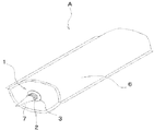
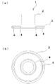
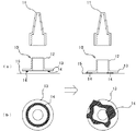
図1は、本発明の実施形態の容器Aの全体構成の斜視図を示し、図2は前記容器押出口基体1の平面図と断面図である。前記押出口基体1の貼着状況を図4に示す。
FIG. 1 is a perspective view of the overall configuration of a container A according to an embodiment of the present invention. FIG. 2 is a plan view and a cross-sectional view of the
図1に示す、パウチ6は、船底形のパウチであり、2枚の略矩形のフィルムの一端部に変形六角形のフィルムを配し、該変形六角形のフィルムの全周を該略矩形のフィルムに対して融着するとともに、両側の縁部において該略矩形のフィルム同士を融着したものである。
A
前記フィルムの材質としては、内容物がシーリング材の場合は、ガスに対するバリア性を有する材質、例えば、アルミ箔をガスバリア層および水蒸気バリア層として、その片側に延伸ポリアミド樹脂を、他方の側には低密度ポリエチレン樹脂層もしくは未延伸ポリプロピレン樹脂層を積層したフィルム等がある。また内容物がガスに対するバリア性を要求しない内容物の場合は、延伸ポリアミド樹脂層の片面に、低密度ポリエチレン樹脂層もしくは未延伸ポリプロピレン樹脂層を積層したフィルム等がある。 As the material of the film, when the content is a sealing material, a material having a gas barrier property, for example, aluminum foil as a gas barrier layer and a water vapor barrier layer, a stretched polyamide resin on one side and a stretched polyamide resin on the other side Examples include a film in which a low density polyethylene resin layer or an unstretched polypropylene resin layer is laminated. When the content does not require gas barrier properties, there is a film in which a low-density polyethylene resin layer or an unstretched polypropylene resin layer is laminated on one side of a stretched polyamide resin layer.
以上の構造よりなるパウチ6内にシーリング材等の高粘性流体を収容して密閉した状態では、押出口基体1を貼着する面のフィルムはほぼ平坦となり、後述する押出口基体1を貼着しやすくなる。
In a state in which a high-viscosity fluid such as a sealing material is accommodated and sealed in the
図2に示すように、前記押出口基体1は、外周面に雄ねじが成形された筒状部2と、容器6に貼着される円形のフランジ部3からなる。樹脂の射出成形により前記筒状部2と前記フランジ部3を一体成形する。この際、前記フランジ部3の前記パウチ6に貼着される面には、前記フランジ部3の中心側および外側の二箇所に、前記フランジ3と同心円の環状に配置された溝形状4を成形する。この際用いる樹脂は、ポリエチレン樹脂、他には、ポリプロピレン樹脂、ABS樹脂、塩ビ樹脂等を使用するが、特に限定するものではない。又樹脂以外の材料で成形することも可能である。
As shown in FIG. 2, the
前記溝形状4の深さは、前記フランジ部3の厚さの50%以内とするのが好ましい。さらに好ましくは、前記フランジ部3の厚さの30%以内とするのがよい。
The depth of the
前記押出口基体1に接着剤層5を積層する。この時前記2個の環状に配置された溝形状4に前記接着剤層5を積層する。そして、高粘性流体を収容し密閉した前記パウチ6に前記押出口基体1を貼着する。
An
貼着の際、従来の押出口基体であれば、接着剤層は押圧されて不規則に広がっていたが、本実施形態の押出口基体1は、図4に示すように、余分な接着剤層5の多くは、前記接着剤層5を積層した際に前記溝形状4生ずる空隙に押し込まれ、前期溝形状4の位置に前記接着剤層5の多くが固定され、前記接着剤層5のはみ出す可能性を少なくすることができる。これにより均一な接着面が成形される。
At the time of sticking, in the case of a conventional extrusion port substrate, the adhesive layer was pressed and spread irregularly, but the
本実施形態の容器Aを使用する際は、貼着された、前記押出口基体1の内側を適当な突き棒等によって破り穿孔する。そして、同じく樹脂の射出成形により得られた押出しノズル7の雌ねじを、前記押出口基体1の雄ねじにねじ込み固定し、前記押出しノズル7の先端を適当な位置で切断し開放する。前記容器Aを市販の押出ガン等にセットし、内容物を押し出して用いる。
When the container A of this embodiment is used, the inside of the stuck
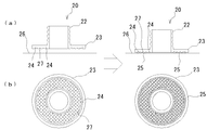
図5に示す、別の実施形態の押出口基体20を有する容器について説明する。
The container which has the extrusion port base |
本実施形態の容器は、前記実施形態の容器Aのパウチ6、押出しノズル7と同じ形状の、パウチ26、押出しノズルを用いる。前記容器Aの押出口基体1と異なる押出口基体20について、ここで説明する。
The container of this embodiment uses the
本実施形態の押出口基体20は、前記実施形態の押出口基体1と異なり、フランジ部23の貼着面に、環状に配置された溝形状24に加え複数の円形の窪み27が成形されている。
Unlike the
本実施形態の容器の押出口基体20の成形方法は、前記実施形態の押出口基体1と同様に、樹脂の射出成形により、外周面に雄ねじが成形された筒状部22と、パウチ26に貼着されるフランジ部23を一体成形する。この際、前記フランジ部23のパウチ26に貼着される面には、前記フランジ部23の中心側および外側の二箇所に、前記フランジ部23と同心円の環状に配置された溝形状24を成形する。また、前記フランジ部23の表面の前記二箇所の環状に配置された前記溝形状24に囲まれた範囲に、複数の円形の窪み27を等間隔で成形する。この際用いる樹脂は、前記実施形態と同様、ポリエチレン樹脂、他には、ポリプロピレン樹脂、ABS樹脂、塩ビ樹脂等を使用するが、特に限定するものではない。又樹脂以外の材料で成形することも可能である。
The molding method of the
前記溝形状24および複数の円形の窪み27の深さは、前記フランジ部23の厚さの50%以内とするのが好ましい。さらに好ましくは、前記フランジ部23の厚さの30%以内とするのがよい。
The depth of the
このようにして得られた前記押出口基体20を、高粘性流体を収容し密閉した前記パウチ26に貼着する時、前記フランジ部23の表面の前記2本の環状の溝形状24で囲まれた範囲に接着剤層25を積層する。そのあと、前記押出口基体20を前記パウチ26に貼着すると、余分な接着剤層25の多くは、前記円形の窪み27および前記2本の溝形状24に生じた空隙に押し込まれ、接着剤層25がはみ出す可能性を減少することができ、均一な接着面が成形される。また本実施形態では、2本の環状の溝形状24に囲まれた範囲が接着面となるので、接着面積が広くなり、より強固な接着が可能となる。
When the
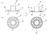
図6に示す、さらに別の実施形態について説明する。本実施形態の説明も他の実施形態と異なる押出口基体30について説明する。
Still another embodiment shown in FIG. 6 will be described. In the description of this embodiment, the
本実施形態の容器は押出口基体30以外は、前記実施形態の容器Aと同じ構成、同じ素材を用いる。本実施形態の容器は押出口基体30は、フランジ部33の貼着面に、2本の環状に配置された溝形状34の間に放射状に配置された溝形状27をさらに有している。
The container of this embodiment uses the same configuration and the same material as the container A of the above embodiment except for the
本実施形態の容器の押出口基体30の成形方法は、他の実施形態と同様に、樹脂の射出成形により、外周面に雄ねじが成形された筒状部32と、パウチ36に貼着されるフランジ部33を一体成形する。この際、前記フランジ部33の前記パウチ36に貼着される面には、前記フランジ部33の中心側および外側の二箇所に、前記フランジ33と同心円の2本の環状に配置された溝形状34を成形する。また、前記フランジ部33の表面の前記2本の環状に配置された溝形状34に囲まれた範囲に、円形フランジ部33の中心から放射状に配置された溝形状37を等間隔に16本成形する。この際用いる樹脂は、前記実施形態と同様、ポリエチレン樹脂、他には、ポリプロピレン樹脂、ABS樹脂、塩ビ樹脂等の樹脂を使用するが、特に限定するものではない。又樹脂以外の材料で成形することも可能である。
As in the other embodiments, the method of molding the
前記溝形状34および放射状に配置された溝形状37の深さは、前記フランジ部33の厚さの50%以内とするのが好ましい。さらに好ましくは、前記フランジ部33の厚さの30%以内とするのがよい。
The depths of the groove shapes 34 and the radially arranged groove shapes 37 are preferably within 50% of the thickness of the
このようにして得られた前記押出口基体30を、高粘性流体を収容し密閉した前記パウチ36に貼着する時、フランジ部33の表面の前記2本の環状に配置された溝形状34および複数の放射状に配置された溝形状37に接着剤層35を積層する。そのあと、前記押出口基体30を前記パウチ36に貼着すると、余分な接着剤層35の多くは、前記2本の環状の溝形状34および前記複数の放射状の溝形状37に生じた空隙に押し込まれ、はみ出す可能性は少なくなり、均一な接着面が成形され、均一でより強固な接着が可能となり、より堅固な接着部を有する容器が得られる。
When the
A 容器
1 押出口基体
2 筒状部
3 フランジ部
4 溝形状
5 接着剤層
6 パウチ
7 押出しノズル
10 押出口基体
11 押出しノズル
12 筒状部
13 フランジ部
14 接着剤層
15 パウチ
20 押出口基体
22 筒状部
23 フランジ部
24 溝形状
25 接着剤層
26 パウチ
27 円形の窪み
30 押出口基体
32 筒状部
33 フランジ部
34 溝形状
35 接着剤層
36 パウチ
37 放射状に配置された溝形状
A
Claims (9)
Priority Applications (1)
| Application Number | Priority Date | Filing Date | Title |
|---|---|---|---|
| JP2004120214A JP2005298042A (en) | 2004-04-15 | 2004-04-15 | Highly viscous fluid container |
Applications Claiming Priority (1)
| Application Number | Priority Date | Filing Date | Title |
|---|---|---|---|
| JP2004120214A JP2005298042A (en) | 2004-04-15 | 2004-04-15 | Highly viscous fluid container |
Publications (1)
| Publication Number | Publication Date |
|---|---|
| JP2005298042A true JP2005298042A (en) | 2005-10-27 |
Family
ID=35330066
Family Applications (1)
| Application Number | Title | Priority Date | Filing Date |
|---|---|---|---|
| JP2004120214A Pending JP2005298042A (en) | 2004-04-15 | 2004-04-15 | Highly viscous fluid container |
Country Status (1)
| Country | Link |
|---|---|
| JP (1) | JP2005298042A (en) |
Cited By (4)
| Publication number | Priority date | Publication date | Assignee | Title |
|---|---|---|---|---|
| JP2007226913A (en) * | 2006-02-24 | 2007-09-06 | Matsushita Electric Ind Co Ltd | Optical device |
| JP2015058972A (en) * | 2013-09-20 | 2015-03-30 | 大王製紙株式会社 | Lid for wet sheet packaging body and wet sheet packaging body |
| WO2016151747A1 (en) * | 2015-03-24 | 2016-09-29 | 三菱重工業株式会社 | Impeller cover, rotary machine, and impeller cover manufacturing method |
| JP2020147295A (en) * | 2019-03-11 | 2020-09-17 | 藤森工業株式会社 | Container and its manufacturing method |
Citations (2)
| Publication number | Priority date | Publication date | Assignee | Title |
|---|---|---|---|---|
| JPH09510422A (en) * | 1994-03-16 | 1997-10-21 | ザ ウエスト カンパニー,インコーポレーテツド | Diaphragm perforation closure and delivery assembly |
| JP2003160182A (en) * | 2001-11-22 | 2003-06-03 | Kaito Kagaku Kogyo Kk | Vessel |
-
2004
- 2004-04-15 JP JP2004120214A patent/JP2005298042A/en active Pending
Patent Citations (2)
| Publication number | Priority date | Publication date | Assignee | Title |
|---|---|---|---|---|
| JPH09510422A (en) * | 1994-03-16 | 1997-10-21 | ザ ウエスト カンパニー,インコーポレーテツド | Diaphragm perforation closure and delivery assembly |
| JP2003160182A (en) * | 2001-11-22 | 2003-06-03 | Kaito Kagaku Kogyo Kk | Vessel |
Cited By (8)
| Publication number | Priority date | Publication date | Assignee | Title |
|---|---|---|---|---|
| JP2007226913A (en) * | 2006-02-24 | 2007-09-06 | Matsushita Electric Ind Co Ltd | Optical device |
| JP2015058972A (en) * | 2013-09-20 | 2015-03-30 | 大王製紙株式会社 | Lid for wet sheet packaging body and wet sheet packaging body |
| WO2016151747A1 (en) * | 2015-03-24 | 2016-09-29 | 三菱重工業株式会社 | Impeller cover, rotary machine, and impeller cover manufacturing method |
| JPWO2016151747A1 (en) * | 2015-03-24 | 2017-12-14 | 三菱重工業株式会社 | Impeller cover, rotating machine, and method of manufacturing impeller cover |
| US10683870B2 (en) | 2015-03-24 | 2020-06-16 | Mitsubishi Heavy Industries Engine & Turbocharger, Ltd. | Impeller cover, rotary machine, and impeller cover manufacturing method |
| JP2020147295A (en) * | 2019-03-11 | 2020-09-17 | 藤森工業株式会社 | Container and its manufacturing method |
| WO2020184558A1 (en) * | 2019-03-11 | 2020-09-17 | 藤森工業株式会社 | Container and production method thereof |
| JP7353045B2 (en) | 2019-03-11 | 2023-09-29 | 藤森工業株式会社 | Container and its manufacturing method |
Similar Documents
| Publication | Publication Date | Title |
|---|---|---|
| US20050006413A1 (en) | Container and pusiier | |
| JP2004231280A (en) | Synthetic resin container | |
| CN116177023A (en) | Tube container and manufacturing method thereof | |
| US9919847B2 (en) | Integrated squeezable dispensing container | |
| US3976217A (en) | Cap liner construction | |
| JP2015145266A (en) | Bag body with pouring tool | |
| CN106794916A (en) | Lamination peel container | |
| JP2022509350A (en) | Multi-piece mounting device for fluid containers | |
| US20180334310A1 (en) | Container with an inner bag | |
| EP1284163B1 (en) | Container | |
| JP6336512B2 (en) | Container with cap | |
| JP2011148512A (en) | Closable tube container | |
| JP2023542173A (en) | Container cap and container assembly to which it is combined | |
| CN111503108A (en) | Nylon glue bonding nut | |
| CN212297185U (en) | Nylon glue bonding nut | |
| JPH0715559U (en) | Discharge container | |
| JP2008239225A (en) | Releasable laminate refill container, manufacturing method of releasable laminate container, and releasable laminate container | |
| JP3973015B2 (en) | container | |
| JP2004231270A (en) | Synthetic resin container | |
| JP5915211B2 (en) | Lid material | |
| JPH11221891A (en) | Tube container | |
| KR100568661B1 (en) | Manufacturing method of high barrier tube | |
| CN104787453A (en) | Packaging hose enabling content to be extruded in quantitative mode and manufacturing method thereof | |
| JP6759854B2 (en) | Tube container | |
| JP2017065104A (en) | Manufacturing method of container, manufacturing of package body, container and package body |
Legal Events
| Date | Code | Title | Description |
|---|---|---|---|
| A621 | Written request for application examination |
Free format text: JAPANESE INTERMEDIATE CODE: A621 Effective date: 20070413 |
|
| A977 | Report on retrieval |
Free format text: JAPANESE INTERMEDIATE CODE: A971007 Effective date: 20091118 |
|
| A131 | Notification of reasons for refusal |
Free format text: JAPANESE INTERMEDIATE CODE: A131 Effective date: 20091201 |
|
| A02 | Decision of refusal |
Free format text: JAPANESE INTERMEDIATE CODE: A02 Effective date: 20100330 |