WO2016151720A1 - 音声補正装置 - Google Patents
音声補正装置 Download PDFInfo
- Publication number
- WO2016151720A1 WO2016151720A1 PCT/JP2015/058677 JP2015058677W WO2016151720A1 WO 2016151720 A1 WO2016151720 A1 WO 2016151720A1 JP 2015058677 W JP2015058677 W JP 2015058677W WO 2016151720 A1 WO2016151720 A1 WO 2016151720A1
- Authority
- WO
- WIPO (PCT)
- Prior art keywords
- correction
- sound
- microphone
- information
- measurement
- Prior art date
- Legal status (The legal status is an assumption and is not a legal conclusion. Google has not performed a legal analysis and makes no representation as to the accuracy of the status listed.)
- Ceased
Links
Images






Classifications
-
- H—ELECTRICITY
- H04—ELECTRIC COMMUNICATION TECHNIQUE
- H04R—LOUDSPEAKERS, MICROPHONES, GRAMOPHONE PICK-UPS OR LIKE ACOUSTIC ELECTROMECHANICAL TRANSDUCERS; ELECTRIC HEARING AIDS; PUBLIC ADDRESS SYSTEMS
- H04R3/00—Circuits for transducers
- H04R3/04—Circuits for transducers for correcting frequency response
Definitions
- the present invention relates to a sound correction device that corrects output sound of an acoustic device or the like.
- sound quality can be adjusted according to the installation environment of the audio equipment.
- the vehicle acoustic device 300 acquires the sound setting information of the external sound source device 100, and the sound setting correction unit 302 performs conversion based on the output characteristics unique to the external sound source device 100, and further, It is described that music or the like is reproduced by performing correction in consideration of the output characteristics of the vehicle acoustic device 300 itself.
- the vehicle audio device 300 to be applied is connected in the case where the vehicle installed such as a car audio marketed at a store or a device to which a speaker to be connected is not specified in advance. It is possible to take into account the sound setting information of a portable music player or the like, but the characteristics of the connected speaker, the echo characteristics in the vehicle, and the characteristics such as attenuation due to the seat and interior materials are not known. Therefore, even if the output characteristics of the vehicular acoustic device 300 itself are known, correction in accordance with the in-vehicle environment may be insufficient.
- a microphone, arithmetic unit, etc. are installed in car audio, etc., the sound from the speaker is recorded with the microphone, the parameter that optimizes the characteristics is calculated, and the parameter is reflected when the sound is played back. Can also be played. In this case, however, a microphone and an advanced arithmetic device are required, which is expensive.
- an object of the present invention is to provide an audio correction device that can correct an output audio suitable for an environment in which an acoustic device is installed.
- the invention according to claim 1 is an audio correction device that includes a microphone and generates correction information for correcting an output sound of an audio device, and causes the audio device to output a measurement sound.
- a measurement unit that measures the measurement sound via the microphone, and a correction information generation unit that generates the correction information based on a measurement result measured by the measurement unit, which is separate from the acoustic device. It is comprised,
- the voice correction device characterized by the above-mentioned.
- the invention according to claim 9 is an audio correction method for an audio correction apparatus that is configured separately from an audio device, includes a microphone, and generates correction information for correcting an output sound of the audio device. Based on the measurement step of outputting the measurement sound to the acoustic device and measuring the measurement sound through the microphone, the characteristics of the microphone acquired in the characteristic information acquisition step, and the measurement result measured in the measurement step And a correction information generation step of generating the correction information.
- the invention described in claim 10 is a sound correction program characterized by causing a computer to execute the sound correction method according to claim 9.
- the invention described in claim 11 is a computer-readable recording medium in which the sound correction program according to claim 10 is stored.
- FIG. 6 It is the block diagram which showed the connection structure of the smart phone concerning one Example of this invention, vehicle equipment, and a server. It is a functional block diagram of the smart phone shown by FIG. It is a function block diagram of the vehicle equipment shown by FIG. It is a function block diagram of the server shown by FIG. It is a flowchart of the sound quality correction
- movement in the smart phone shown by FIG. 6 is a flowchart of a microphone characteristic correction operation shown in FIG. 6 is a flowchart of a measurement direction determination operation shown in FIG. 5.
- 6 is a flowchart of the measurement operation shown in FIG. 6 is a flowchart of a correction information generation operation shown in FIG. It is an example of a screen display of direction designation.
- the sound correction apparatus is configured separately from the acoustic device, and the measurement unit outputs the measurement sound to the acoustic device and measures the measurement sound through the microphone. Then, correction information is generated based on the characteristics of the microphone acquired by the characteristic information acquisition unit and the measurement result measured by the measurement unit in the correction information generation unit. In this way, correction information can be generated using a microphone that is separate from the audio device, and the output sound is corrected to be suitable for the environment in which the audio device such as the car audio is installed. be able to. Moreover, since it is a separate body from the audio equipment, correction in a plurality of environments can be easily performed.
- the microphone itself may not have high performance.
- the output sound of an audio device such as a car audio can be easily corrected using a device such as a smartphone provided with a microphone in advance. be able to.
- a characteristic information acquisition unit that acquires the characteristic information of the microphone is further provided, and the correction information generation unit generates correction information based on the characteristics of the microphone acquired by the characteristic information acquisition unit and the measurement result measured by the measurement unit. Also good. In this way, correction information can be generated in consideration of the characteristics of the microphone that measures the measurement sound, and it is suitable for an environment where an audio device such as a car audio is installed without depending on the characteristics of the microphone. The output sound can be corrected.
- it further comprises a direction information acquisition unit that acquires information about the direction of the microphone, and the measurement unit is based on the information about the direction acquired by the direction information acquisition unit and the direction of the microphone when measuring the characteristic information of the microphone.
- the measurement sound may be output to an acoustic device and the measurement sound may be measured via a microphone. In this way, since the direction of the microphone can be taken into consideration, correction independent of the characteristics of the microphone can be performed.
- the correction information generation unit may generate microphone correction information obtained by correcting the measurement result of the measurement unit based on the characteristic information of the microphone, and may generate correction information based on the microphone correction information. By doing so, it is possible to generate microphone characteristic information that does not depend on the characteristics of the microphone from the measurement result, and correct the output sound to be suitable for an environment in which an audio device such as a car audio is installed based on the information. .
- the measurement unit may record measurement sound
- the correction information generation unit may generate correction information based on the measurement sound recorded by the measurement unit. In this way, since the measurement sound can be recorded, correction information can be generated even when the processing capability is low and real-time processing is difficult.
- an output unit that outputs the correction information to the audio equipment may be further provided. By doing so, the generated correction information can be automatically corrected by the audio equipment.
- the image processing apparatus may further include a correction range information acquisition unit that acquires information regarding the correction range in the audio device, and the correction information generation unit may generate correction information based on the information regarding the correction range acquired by the correction range information acquisition unit. .
- correction information can be generated based on information related to the correction range of the audio device such as the number of bands of the correction unit such as an equalizer included in the audio device, the center frequency, the Q value, and the gain.
- the audio equipment may be provided in the moving body. By doing in this way, it can correct
- the audio correction method is an audio correction apparatus configured separately from an audio device, in which the measurement process causes the audio device to output measurement sound and measures the measurement sound via a microphone. To do. Then, the correction information generation step generates correction information based on the characteristics of the microphone acquired in the characteristic information acquisition step and the measurement result measured in the measurement step. In this way, correction information can be generated using a microphone that is separate from the audio device, and the output sound is corrected to be suitable for the environment in which the audio device such as the car audio is installed. be able to. Moreover, since it is a separate body from the audio equipment, correction in a plurality of environments can be easily performed.
- a sound correction program that causes the above-described sound correction method to be executed by a computer may be used. By doing so, it is possible to generate correction information using a microphone that is a separate device from the acoustic device using a computer, and it is suitable for an environment where an acoustic device such as a car audio is installed. The output sound can be corrected. Moreover, since it is a separate body from the audio equipment, correction in a plurality of environments can be easily performed.
- the above-described audio correction program may be stored in a computer-readable recording medium.
- the program can be distributed as a single unit in addition to being incorporated in the device, and version upgrades can be easily performed.
- FIG. 1 shows a connection configuration of a smartphone 1 as an audio correction device according to the present embodiment, an in-vehicle device 2 as an acoustic device, and a server 4.
- the smartphone 1 can communicate with the in-vehicle device 2 wirelessly.
- communication can be performed wirelessly, but communication may be possible using wired communication such as USB (Universal Serial Bus).
- USB Universal Serial Bus
- the smartphone 1 is configured separately from the in-vehicle device 2.
- the in-vehicle device 2 is a device that is installed in a vehicle interior of a vehicle and that reproduces sound, such as a car audio or a car navigation system.
- the in-vehicle device 2 is connected to speakers 3L and 3R. Note that the number of speakers is not limited to two and may be three or more.
- the smartphone 1 can communicate with the server 4 wirelessly.
- the server 4 can communicate with the smartphone 1 via, for example, the Internet.
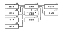
- the smartphone 1 includes a reception unit 11, a transmission unit 12, a calculation unit 13, a white noise generation unit 14, a microphone 15, a recording unit 16, a display unit 17, and a G sensor 18. And an operation unit 19.
- the receiving unit 11 receives from the in-vehicle device 2 acoustic characteristic correction possible range information (information regarding the correction range in the acoustic device) and the like which will be described later.
- the received acoustic characteristic correction possible range information is output to the calculation unit 13.
- the receiving unit 11 receives microphone characteristic information of the smartphone 1 from the server 4.
- the reception unit 11 functions as a correction range information acquisition unit that acquires information about the correction range in the acoustic device and a characteristic information acquisition unit that acquires characteristic information of the microphone 15.
- the transmission unit 12 transmits to the in-vehicle device 2 acoustic characteristic correction amount information, which will be described later, input from the calculation unit 13, white noise voice information input from the white noise generation unit 14, and the like.
- the transmission unit 12 transmits model information of the smartphone 1 to the server 4.
- the reception unit 11 and the transmission unit 12 are configured to communicate with the in-vehicle device 2 (Bluetooth (registered trademark), USB, etc.) and communicate with the server 4 (LTE (Long Term Term Evolution) or wireless LAN (Local Area Network). ) Etc.).
- the server 4 LTE (Long Term Term Evolution) or wireless LAN (Local Area Network).
- the calculation unit 13 estimates the orientation of the smartphone 1 based on the output of the G sensor 18. Further, the calculation unit 13 causes the white noise generation unit 14 to generate white noise sound, and causes the recording unit 16 to record the white noise sound reproduced by the in-vehicle device 2 via the microphone 15. In addition, the arithmetic unit 13 corrects the characteristics of the microphone 15 based on the microphone characteristic information received from the server 4 for the white noise sound recorded in the recording unit 16. And the calculating part 13 produces
- the white noise generation unit 14 generates white noise sound as measurement sound.
- white noise sound is used as the measurement sound.
- the sound is suitable for measuring the frequency characteristics of the vehicle-mounted device 2 such as an impulse response impulse, the speakers 3L and 3R, and the vehicle interior. If it is.
- the microphone 15 collects white noise sound reproduced by the in-vehicle device 2. Note that the microphone 15 is not a dedicated one but may be used for a telephone call or the like.
- the recording unit 16 records white noise sound collected by the microphone 15.
- the recording unit records white noise sound in a storage medium such as a memory (not shown).
- the display unit 17 is composed of, for example, a liquid crystal display, and displays the result of correction related to the characteristics of the microphone 15 calculated by the calculation unit 13, the acoustic characteristic correction amount information generated thereafter, and the like. Of course, the display unit 17 may display other functions (call, mail, etc.) of the smartphone 1.
- the G sensor 18 is a so-called acceleration sensor. For example, if it is a three-axis acceleration sensor, it can measure acceleration in three directions of the XYZ axes.
- the G sensor 18 outputs the measured acceleration to the calculation unit 13. That is, since gravity is applied to the ground direction, the acceleration output from the G sensor 18 becomes information regarding the direction of the microphone 15, and the G sensor 18 functions as a direction information acquisition unit.
- the operation unit 19 includes a push button, a touch panel, and the like, and information related to an operation input by a user or the like is output to the calculation unit 13.
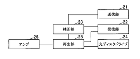
- the in-vehicle device 2 includes a transmission unit 21, a reception unit 22, a correction unit 23, an optical disk drive 24, a reproduction unit 25, and an amplifier 26.
- the transmission unit 21 transmits the acoustic characteristic correction possible range information input from the correction unit 23 to the smartphone 1.
- the receiving unit 22 receives acoustic characteristic correction amount information, white noise voice information, and the like from the smartphone 1.
- the received acoustic characteristic correction amount information is output to the correction unit 23, and the white noise audio information is output to the reproduction unit 25.
- the correction unit 23 corrects the audio signal reproduced by the reproduction unit 25 by setting a gain or the like for each of a plurality of frequency bands based on the acoustic characteristic correction amount information input from the reception unit 22.
- the optical disc drive 24 is a device that reads audio information from an optical disc on which audio information such as music such as a CD (Compact Disc), DVD (Digital Versatile Disc), and Blu-ray disc is recorded.
- an optical disk is used as a recording medium on which audio information such as music is recorded.
- the present invention is not limited to this, and a hard disk, a semiconductor memory, or the like may be used.
- the sound of radio broadcasting or television broadcasting may be used.
- the playback unit 25 plays back the audio information read by the optical disc drive 24 and outputs it to the amplifier 26.
- the amplifier 26 amplifies the audio signal reproduced by the reproducing unit 25 by a predetermined amount and outputs the amplified signal to the speakers 3L and 3R.
- the server 4 includes a transmission unit 41, a reception unit 42, a calculation unit 43, and a microphone characteristic storage unit 44.
- the transmission unit 41 transmits the microphone characteristic information input from the calculation unit 43 to the smartphone 1.
- the receiving unit 42 receives model information and the like from the smartphone 1.
- the receiving unit 42 outputs the received model information and the like to the calculation unit 43.
- the calculation unit 43 reads out the microphone characteristic corresponding to the model from the microphone characteristic storage unit 44 based on the model information received by the reception unit 42 and transmits the microphone characteristic to the smartphone 1 via the transmission unit 41.
- the microphone characteristic storage unit 44 is a recording medium in which microphone characteristics for each model of the plurality of smartphones 1 are stored.
- the microphone characteristic is a frequency characteristic corresponding to the direction of the microphone (direction of the smartphone 1 itself) in the model.
- the smartphone 1 has different recording characteristics due to differences in microphone position and performance depending on the model. Therefore, the frequency characteristics of the microphone 15 of the smartphone 1 are obtained by measuring the speaker and the smartphone 1 whose characteristics are known in advance in an environment where ideal recording is possible such as an anechoic room.
- This microphone characteristic may be measured for each direction of the plurality of smartphones 1 (that is, the direction of the microphone) and stored in the microphone characteristic storage unit 44, or only in one specific direction.
- the model stored in the microphone characteristic storage unit 44 is not limited to the smartphone 1, and a device such as a mobile phone that includes a microphone and can function as an audio correction device may be included.
- step S11 the application is activated and the process proceeds to step S12.
- the application is a sound correction program for executing the sound quality correction method according to the present embodiment. This application is installed in the smartphone 1 in advance or by downloading.
- step S12 as the characteristic information acquisition step, the microphone characteristic of the smartphone 1 is acquired from the server 4 and the process proceeds to step S13.
- the smartphone 1 transmits preset model information to the server 4 via the transmission unit 12 (step S21).
- the calculation unit 43 selects the microphone characteristic of the model stored in the microphone characteristic storage unit 44 based on the model information received by the reception unit 42, and the smartphone via the transmission unit 41 as microphone characteristic information. 1 to send.
- the smartphone 1 acquires the microphone characteristic information by receiving the microphone characteristic information with the receiving unit 11 (step S22). Note that once this step S12 is executed, it may not be executed after the next time, for example, when a correction operation is performed in another vehicle.
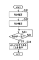
- step S13 the orientation of the smartphone 1 is determined for a measurement operation described later.
- the orientation of the smartphone 1 is determined by the flowchart shown in FIG.
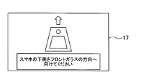
- step S31 of the flowchart of FIG. 7 the orientation of the smartphone 1 is designated to the user of the smartphone 1 or the like, and the process proceeds to step S32.
- the orientation is displayed on a display unit (not shown) of the in-vehicle device 2 or the display unit 17 of the smartphone 1 as shown in FIG.
- the lower side is determined based on the screen display of the smartphone 1.
- the designation of this orientation designates the same orientation as the orientation of the smartphone 1 when measuring the microphone characteristic information.
- the direction of the smartphone 1 is specified, but this is substantially equivalent to specifying the direction of the microphone 15.
- a screen showing the ears of the user who actually listens is displayed on the in-vehicle device 2 and the display portion of the smartphone 1. 17 may be displayed.
- step S32 the orientation of the smartphone 1 is estimated, and the process proceeds to step S33.
- the direction is estimated by a well-known method based on the output (direction information) of the G sensor 18 mounted on the smartphone 1.
- step S33 it is determined whether or not the actual orientation of the smartphone 1 matches the designated orientation. If they match (YES), the process proceeds to step S34, and if they do not match (NO). Repeat this step until they match.
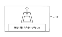
- step S34 for example, the correct orientation is displayed on the screen as shown in FIG. 11, and the flow returns to the flowchart of FIG.
- step S14 measurement is performed in step S14 as a measurement process.
- the measurement is to measure a frequency characteristic at the time of reproduction by the in-vehicle device 2 in a cabin where the in-vehicle device 2 is installed.
- the measurement operation is performed according to the flowchart shown in FIG. That is, the measurement process is performed based on the direction of the microphone (the direction of the smartphone 1) and the direction of the microphone at the time of measuring the characteristic information of the microphone (specified direction).
- a measurement start button or the like is displayed on the display unit 17 of the smartphone 1, and the user or the like operates the button to start measurement, and the process proceeds to step S42. Then, the recording of the sound collected by the microphone 15 is started by the button operation of the user or the like.
- the measurement start button may be displayed not on the smartphone 1 but on the in-vehicle device 2 side, and information indicating the measurement start may be received from the in-vehicle device 2.
- step S42 the white noise generating unit 14 generates white noise sound and transmits the white noise sound information through the transmitting unit 12 as white noise sound information.
- the white noise sound information received by the receiving unit 22 is directly reproduced by the reproduction unit 25, and white noise sound is emitted from the speakers 3 ⁇ / b> L and 3 ⁇ / b> R.
- the sound quality correction operation by the correction unit 23 is not performed on the in-vehicle device 2 side.
- White noise sound radiated from the speakers 3L and 3R is collected from the microphone 15 of the smartphone 1 and recorded in the recording unit 16.
- step S43 after the white noise sound is reproduced by the in-vehicle device 2 for a predetermined time, the measurement (recording) is terminated, and the process returns to the flowchart of FIG. That is, the white noise generation unit 14 stops the generation of white noise sound, and the recording by the recording unit 16 is stopped. The white noise sound recorded by the recording unit 16 becomes the measurement result.
- the calculation unit 13 determines that the direction information acquired by the G sensor 18 (orientation information acquisition unit) matches the direction of the microphone at the time of measuring the characteristic information of the microphone 15. The measurement sound is output to the in-vehicle device 2 (acoustic device), and the measurement sound is measured using the microphone 15.
- the smartphone 1 includes the white noise generation unit 14 and outputs white noise sound to the in-vehicle device 2, but the in-vehicle device 2 generates measurement sound such as white noise sound.
- the smartphone 1 may be configured to transmit a measurement sound output instruction.
- step S15 the measurement result measured in step S14 is corrected based on the microphone characteristic information acquired in step S12, and the process proceeds to step S16.
- the measurement result corrected in this step becomes microphone correction information.
- the measurement performed in step S14 is executed in order to eliminate the influence of the characteristics of the microphone 15.
- the measurement result measured in step S14 is subjected to fast Fourier transform to calculate a frequency characteristic, and correction is performed so that the characteristic of the microphone 15 becomes flat with respect to the frequency characteristic.
- step S16 as the correction information generation step, acoustic characteristic correction amount information for the in-vehicle device 2 is generated, and the process proceeds to step S17.
- the acoustic characteristic correction amount information generation operation is performed according to the flowchart shown in FIG.
- acoustic characteristic correction possible range information (information regarding the correction range) is acquired from the correction unit 23 of the in-vehicle device 2 via the transmission unit 21 and the reception unit 11, and the process proceeds to step S52.
- the acoustic characteristic correction possible information indicates information related to the correction amount of the correction unit 23 included in the in-vehicle device 2. Specifically, it is information related to a sound quality adjustment function such as an equalizer, such as information on the number of bands, center frequency, Q value, upper and lower limits of gain, and the like.
- step S52 based on the acoustic characteristic correction possible range information acquired in step S51 and the measurement result (microphone correction information) after the microphone characteristic is corrected in step S15, the acoustic characteristic for the in-vehicle device 2 is obtained.
- the correction amount information is generated and the process returns to the flowchart of FIG. That is, the calculation unit 13 functions as a correction information generation unit that generates correction information for correcting the output sound of the in-vehicle device 2 based on the characteristics of the microphone 15 and the measurement results.
- step S17 the acoustic characteristic correction amount information is output and the process ends.
- the acoustic characteristic correction amount information is transmitted to the in-vehicle device 2 via the transmission unit 12. That is, the transmission unit 12 functions as an output unit that outputs correction information to the in-vehicle device 2 (acoustic device).
- the correction unit 23 performs a correction operation based on the acoustic characteristic correction amount information received by the reception unit 22.
- acoustic characteristic correction amount information may be displayed on the display part 17 of the smart phone 1, and a user etc. may adjust the vehicle equipment 2 manually.
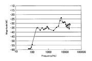
- FIG. 12 shows an example of the frequency characteristic as it is measured (recorded) in step S14.
- the microphone characteristic of 200 Hz or less is difficult to pick up sound. In other words, the bass has been recorded smaller than the actual sound. Therefore, correct correction cannot be performed as it is.
- FIG. 13 is an example of the result of correcting the microphone characteristics in step S15. This state is the actual sound condition in the passenger compartment. However, in FIG. 13, it can be seen that the vehicle-mounted device 2 (speakers 3L and 3R) and the in-vehicle environment have a characteristic in which the vicinity sounds 6 kHz.
- step S16 the acoustic characteristic correction amount information is generated so as to approach the flat frequency characteristic based on the acoustic characteristic correction possible range information of the in-vehicle device 2 and is transmitted to the in-vehicle device 2, and the correction unit 23 of the in-vehicle device 2 Based on the received acoustic characteristic correction amount information, correction is performed as shown in FIG. In the case of FIG. 14, correction was performed so that ⁇ 10 dB centered on 6 kHz, ⁇ 5 dB centered on 10 kHz, and +2 dB centered on 2 kHz. By doing so, it is possible to improve the audibility by making the characteristics close to flat.
- the smartphone 1 is configured separately from the in-vehicle device 2, the characteristic information of the microphone 15 of the smartphone 1 is acquired from the server 4 by the receiving unit 11, and the direction of the smartphone 1 is detected by the G sensor 18. Get information about.
- the calculation unit 13 causes the white noise generation unit 14 to generate white noise sound, causes the vehicle-mounted device 2 to output the white noise sound, and uses the microphone 15 to record the white noise sound to the recording unit 16 and the measurement result. And Then, the calculation unit 13 generates correction information based on the characteristic information of the microphone 15 and the measurement result.
- correction information can be generated in consideration of the characteristics of the microphone of the smartphone 1 and is suitable for an environment in which the vehicle-mounted device 2 such as a car audio is installed without depending on the characteristics of the microphone 15.
- the output sound can be corrected.
- it since it is a separate body from the vehicle-mounted device 2, it can be easily corrected in a plurality of environments such as other vehicles and other acoustic devices.
- the microphone characteristic correction and the generation of correction information are performed after the recording unit 16 has recorded the white noise sound, the correction information can be generated even when real-time processing is difficult due to low processing capability.
- the microphone itself may not have high performance. Therefore, the output of an audio device such as a car audio can be easily performed using a device in which the microphone 15 is provided in advance, such as the smartphone 1. Sound can be corrected.
- the calculation unit 43 causes the in-vehicle device 2 to output white noise sound. Recording from the microphone 15. By doing in this way, since the direction of the microphone 15 can be taken into consideration, correction independent of the characteristics of the microphone 15 can be performed.
- the calculation unit 13 generates microphone correction information in which the measurement result is corrected based on the characteristic information of the microphone 15 and the information related to the orientation of the smartphone 1, and generates correction information based on the microphone correction information.
- the microphone characteristic information which does not depend on the characteristic of the microphone 15 can be produced
- the transmission part 12 which transmits correction information to the vehicle equipment 2 is provided.
- generated can be corrected by the structure of only the vehicle equipment 2 after that the vehicle equipment 2 utilizes.
- the receiving unit 11 acquires the acoustic characteristic correctable range information of the in-vehicle device 2, and the calculation unit 13 generates correction information based on the acoustic characteristic correctable range information acquired by the receiving unit 11.
- correction information can be generated based on the acoustic characteristic correction possible range information of the vehicle-mounted device 2 such as the number of bands of the equalizer, the center frequency, the Q value, and the gain. Accordingly, it is possible to generate correction information optimal for a plurality of types of vehicle-mounted devices using only the smartphone 1.
- the microphone characteristic information for each model is stored in the server 4, it is possible to easily cope with a new model and to easily update the microphone characteristic information.
- the vehicle-mounted device 2 since the vehicle-mounted device 2 is installed in a vehicle such as an automobile, correction can be performed in accordance with the acoustic characteristics of the installed vehicle.
- the in-vehicle device 2 has been described as the acoustic device installed in the vehicle.
- the acoustic device may be installed in a railway vehicle, a ship, an aircraft, or the like. Further, it may be an acoustic device such as a home audio device installed indoors.
- the server 4 is provided, but the smartphone 1 may store characteristic information of the microphone 15.
Landscapes
- Physics & Mathematics (AREA)
- Engineering & Computer Science (AREA)
- Acoustics & Sound (AREA)
- Signal Processing (AREA)
- Circuit For Audible Band Transducer (AREA)
Abstract
音響機器が設置された環境に適した出力音声に補正することができる音声補正装置を提供する。 スマートフォン(1)は車載機(2)とは別体に構成されており、受信部(11)でスマートフォン(1)のマイク(15)の特性情報をサーバ(2)から取得し、Gセンサ(18)でスマートフォン(1)の向きに関する情報を取得する。次に、演算部(13)がホワイトノイズ生成部(14)にホワイトノイズ音声を生成して車載機(2)に当該ホワイトノイズ音声を出力させ、マイク(15)を用いてホワイトノイズ音声を録音部(16)に録音させて測定結果とする。そして、演算部(13)でマイク(15)の特性情報と、スマートフォン(1)の向きに関する情報と、測定結果と、に基づいて補正情報を生成する。
Description
本発明は、音響機器等の出力音声を補正する音声補正装置に関する。
例えばカーオーディオなどの音響機器においては、当該音響機器の設置環境に合わせて音質の調整が可能となっているものが多い。
また、近年では、カーオーディオにおいて、携帯音楽プレーヤ等を接続して、当該携帯音楽プレーヤに記憶されている音楽を再生することも行われている。この際に、携帯音楽プレーヤ等に設定されている音質設定等をカーオーディオが取得して携帯音楽プレーヤで再生した音質に近い音質で再生することが提案されている(例えば特許文献1を参照)。
特許文献1には、車両用音響装置300が、外部音源装置100の音響設定情報を取得し、それを音響設定補正部302が、外部音源装置100に固有の出力特性に基づく変換を行ない、更に車両用音響装置300自体の出力特性を加味した補正を行なって音楽等の再生を行うことが記載されている。
しかしながら、特許文献1に記載された発明では、適用される車両用音響機器300が店頭で市販されているカーオーディオ等の設置される車両や接続されるスピーカが予め特定されない機器の場合、接続された携帯音楽プレーヤ等の音響設定情報を加味することは可能であるが、接続されるスピーカの特性や車内の反響特性及びシートや内装材による減衰などの特性が分からない。従って、車両用音響装置300自体の出力特性が分かっていても、個々の車内環境に合わせた補正は不十分となってしまうことがある。
また、カーオーディオ等にマイクや演算装置等を搭載して、スピーカからの音をマイクで録音し、特性が最適になるようなパラメータを演算して、音声を再生する際に当該パラメータを反映させて再生することも可能である。但し、この場合、マイクと高度な演算装置が必要となりコストがかかる。
そこで、本発明は、上述した問題に鑑み、例えば、音響機器が設置された環境に適した出力音声に補正することができる音声補正装置を提供することを課題とする。
上記課題を解決するために、請求項1に記載の発明は、マイクを備え、音響機器の出力音を補正する補正情報を生成する音声補正装置であって、前記音響機器に測定音を出力させ、前記マイクを介して前記測定音を測定する測定部と、前記測定部が測定した測定結果に基づいて前記補正情報を生成する補正情報生成部と、を備え、前記音響機器とは別体に構成されている、ことを特徴とする音声補正装置である。
また、請求項9に記載の発明は、音響機器とは別体に構成されるとともにマイクを備え、該音響機器の出力音を補正する補正情報を生成する音声補正装置の音声補正方法であって、前記音響機器に測定音を出力させ、前記マイクを介して前記測定音を測定する測定工程と、前記特性情報取得工程で取得した前記マイクの特性及び前記測定工程で測定した測定結果に基づいて前記補正情報を生成する補正情報生成工程と、を含むことを特徴とする音声補正方法である。
また、請求項10に記載の発明は、請求項9に記載の音声補正方法を、コンピュータにより実行させることを特徴とする音声補正プログラムである。
また、請求項11に記載の発明は、請求項10に記載の音声補正プログラムを格納したことを特徴とするコンピュータ読み取り可能な記録媒体である。
以下、本発明の一実施形態にかかる表示装置を説明する。本発明の一実施形態にかかる音声補正装置は、音響機器とは別体に構成されており、測定部で音響機器に測定音を出力させ、マイクを介して測定音を測定する。そして、補正情報生成部で特性情報取得部が取得したマイクの特性及び測定部が測定した測定結果に基づいて補正情報を生成する。このようにすることにより、音響機器とは別体の機器のマイクを利用して、補正情報を生成することができ、カーオーディオ等の音響機器が設置された環境に適した出力音声に補正することができる。また、音響機器とは別体であるので、複数の環境における補正をすることが容易にできる。
また、マイクの特性が取得できればマイク自体が高性能でなくてもよいので、例えばスマートフォン等の予めマイクが設けられている機器を利用して容易にカーオーディオ等の音響機器の出力音を補正することができる。
また、マイクの特性情報を取得する特性情報取得部を更に備え、補正情報生成部は、特性情報取得部が取得したマイクの特性及び測定部が測定した測定結果に基づいて補正情報を生成してもよい。このようにすることにより、測定音を測定するマイクの特性を考慮して、補正情報を生成することができ、マイクの特性に依存しないでカーオーディオ等の音響機器が設置された環境に適した出力音声に補正することができる。
また、マイクの向きに関する情報を取得する向き情報取得部を更に備え、測定部は、向き情報取得部が取得した向きに関する情報と、マイクの特性情報測定時のマイクの向きと、に基づいて、音響機器に測定音を出力させ、マイクを介して測定音を測定してもよい。このようにすることにより、マイクの向きを考慮することができるので、よりマイクの特性に依存しない補正を行うことができる。
また、補正情報生成部は、マイクの特性情報に基づいて測定部の測定結果を補正したマイク補正情報を生成し、該マイク補正情報に基づいて補正情報を生成してもよい。このようにすることにより、測定結果からマイクの特性に依存しないマイク特性情報を生成し、その情報に基づいてカーオーディオ等の音響機器が設置された環境に適した出力音声に補正することができる。
また、測定部は、測定音を録音し、補正情報生成部は、測定部が録音した測定音に基づいて補正情報を生成してもよい。このようにすることにより、測定音を録音することができので、処理能力が低くリアルタイム処理が困難な場合でも補正情報を生成することができる。
また、補正情報を音響機器に出力する出力部を更に備えていてもよい。このようにすることにより、生成された補正情報を音響機器が利用して自動的に補正することができる。
また、音響機器における補正範囲に関する情報を取得する補正範囲情報取得部を更に備え、補正情報生成部は、補正範囲情報取得部が取得した補正範囲に関する情報に基づいて補正情報を生成してもよい。このようにすることにより、音響機器が有するイコライザ等の補正手段のバンド数、中心周波数 、Q値、ゲイン等の音響機器の補正範囲に関する情報に基づいて補正情報を生成することができる。
また、音響機器は移動体に設けられていてもよい。このようにすることにより、自動車等の車両に搭載されるカーオーディオ等の音響機器について、搭載された車両の音響特性に合わせた補正を行うことができる。
また、本発明の一実施形態にかかる音声補正方法は、音響機器とは別体に構成された音声補正装置において、測定工程が音響機器に測定音を出力させ、マイクを介して測定音を測定する。そして、補正情報生成工程が特性情報取得工程で取得したマイクの特性と、測定工程で測定した測定結果と、に基づいて補正情報を生成する。このようにすることにより、音響機器とは別体の機器のマイクを利用して、補正情報を生成することができ、カーオーディオ等の音響機器が設置された環境に適した出力音声に補正することができる。また、音響機器とは別体であるので、複数の環境における補正をすることが容易にできる。
また、上述した音声補正方法をコンピュータにより実行させる音声補正プログラムとしてもよい。このようにすることにより、コンピュータを用いて、音響機器とは別体の機器のマイクを利用して、補正情報を生成することができ、カーオーディオ等の音響機器が設置された環境に適した出力音声に補正することができる。また、音響機器とは別体であるので、複数の環境における補正をすることが容易にできる。
また、上述した音声補正プログラムをコンピュータ読み取り可能な記録媒体に格納してもよい。このようにすることにより、当該プログラムを機器に組み込む以外に単体でも流通させることができ、バージョンアップ等も容易に行える。
本発明の一実施例にかかる音声補正装置を図1乃至図15を参照して説明する。まず、図1に本実施例にかかる音声補正装置としてのスマートフォン1と、音響機器としての車載機2と、サーバ4との接続構成を示す。
スマートフォン1は、車載機2と無線にて通信可能となっている。図1では、無線にて通信可能としているが、USB(Universal Serial Bus)等の有線にて通信可能としてもよい。即ち、スマートフォン1は車載機2とは別体に構成されている。車載機2は、車両の車室内に設置され、例えばカーオーディオやカーナビゲーションシステム等音声の再生が行われる装置である。そして、車載機2はスピーカ3L及び3Rが接続されている。なお、スピーカは2つに限らず3つ以上であってもよい。
また、スマートフォン1は、サーバ4と無線にて通信可能となっている。サーバ4は、例えばインターネットを介してスマートフォン1と通信可能となっている。
スマートフォン1は、図2に示すように、受信部11と、送信部12と、演算部13と、ホワイトノイズ生成部14と、マイク15と、録音部16と、表示部17と、Gセンサ18と、操作部19と、を備えている。
受信部11は、車載機2から後述する音響特性補正可能範囲情報(音響機器における補正範囲に関する情報)等を受信する。受信した音響特性補正可能範囲情報は演算部13に出力する。また、受信部11は、サーバ4からスマートフォン1のマイク特性情報等を受信する。即ち、受信部11は、音響機器における補正範囲に関する情報を取得する補正範囲情報取得部、マイク15の特性情報を取得する特性情報取得部として機能する。
送信部12は、車載機2に対して、演算部13から入力される後述する音響特性補正量情報及びホワイトノイズ生成部14から入力されるホワイトノイズ音声情報等を送信する。また、送信部12は、サーバ4に対してスマートフォン1の機種情報等を送信する。
即ち、受信部11及び送信部12は、車載機2との通信機能(Bluetooth(登録商標)やUSB等)と、サーバ4との通信機能(LTE(Long Term Evolution)や無線LAN(Local Area Network)等)と、を備えている。
演算部13は、Gセンサ18の出力に基づいてスマートフォン1の向きを推定する。また、演算部13は、ホワイトノイズ生成部14にホワイトノイズ音声を生成させ、録音部16に車載機2が再生したホワイトノイズ音声をマイク15を介して録音させる。また、演算部13は、録音部16に録音されたホワイトノイズ音声をサーバ4から受信したマイク特性情報に基づいてマイク15の特性にかかる補正を行う。そして、演算部13は、マイク15の特性にかかる補正の結果に基づいて、車載機2の音響特性補正量情報を生成する。
ホワイトノイズ生成部14は、測定音としてのホワイトノイズ音声を生成する。なお、本実施例では測定音としてホワイトノイズ音声で説明するが、インパルス応答用のインパルス等の車載機2と、スピーカ3L及び3Rと、車室内と、の周波数特性を測定するのに適した音声であればよい。
マイク15は、車載機2で再生したホワイトノイズ音声を集音する。なお、マイク15は、専用のものではなく、通話等に利用されるものでよい。
録音部16は、マイク15が集音したホワイトノイズ音声を録音する。録音部は、図示しないメモリ等の記憶媒体にホワイトノイズ音声を録音する。
表示部17は、例えば液晶ディスプレイ等で構成され、演算部13で演算されたマイク15の特性にかかる補正の結果や、その後生成される音響特性補正量情報等を表示する。勿論表示部17は、スマートフォン1の他の機能(通話、メール等)の表示を行ってもよい。
Gセンサ18は、所謂加速度センサであり、例えば3軸加速度センサであれば、XYZ軸の3方向の加速度を測定できる。Gセンサ18は、測定された加速度を演算部13に出力する。即ち、重力が地面方向にかかっているため、Gセンサ18が出力する加速度が、マイク15の向きに関する情報となり、Gセンサ18は、向き情報取得部として機能する。
操作部19は、押しボタンやタッチパネル等で構成され、ユーザ等が入力した操作に関する情報が演算部13に出力される。
車載機2は、図3に示すように、送信部21と、受信部22と、補正部23と、光ディスクドライブ24と、再生部25と、アンプ26と、を備えている。
送信部21は、スマートフォン1に対して、補正部23から入力される音響特性補正可能範囲情報等を送信する。
受信部22は、スマートフォン1から音響特性補正量情報及びホワイトノイズ音声情報等を受信する。受信した音響特性補正量情報は補正部23に出力され、ホワイトノイズ音声情報は再生部25に出力される。
補正部23は、受信部22から入力された音響特性補正量情報に基づいて、複数の周波数帯域毎にゲイン等を設定して再生部25が再生する音声信号を補正する。
光ディスクドライブ24は、CD(Compact Disc)、DVD(Digital Versatile Disc)、ブルーレイディスク等の音楽等の音声情報が記録された光ディスクから音声情報等を読み出す装置である。なお、本実施例では、音楽等の音声情報が記録された記録媒体として光ディスクとしているが、それに限らず、ハードディスクや半導体メモリ等であってもよい。また、ラジオ放送やテレビ放送の音声であってもよい。或いは、スマートフォン1に格納されている音楽等、外部から通信等により入力される音声情報であってもよい。
再生部25は、光ディスクドライブ24が読み出した音声情報を再生してアンプ26に出力する。
アンプ26は、再生部25で再生された音声信号を所定量増幅してスピーカ3L及び3Rに出力する。
サーバ4は、図4に示すように、送信部41と、受信部42と、演算部43と、マイク特性格納部44と、を備えている。
送信部41は、スマートフォン1に対して、演算部43から入力されたマイク特性情報等を送信する。
受信部42は、スマートフォン1から機種情報等を受信する。受信部42は、受信した機種情報等を演算部43に出力する。
演算部43は、受信部42が受信した機種情報に基づいて、マイク特性格納部44から当該機種に該当するマイク特性を読み出して送信部41を介してスマートフォン1に送信する。
マイク特性格納部44は、複数のスマートフォン1の機種ごとのマイク特性が格納されている記録媒体である。マイク特性は、当該機種におけるマイクの向き(スマートフォン1自体の向き)に応じた周波数特性である。スマートフォン1は機種によってマイク位置や性能の違いから録音特性が異なる。そこで、予め特性の判明しているスピーカとスマートフォン1を無響室など理想的な録音ができる環境で測定し、当該スマートフォン1のマイク15の周波数特性を得たものである。このマイク特性は、複数のスマートフォン1の向き(即ち、マイクの向き)毎に特性を測定してマイク特性格納部44に格納してもよいし、特定の1方向のみであってもよい。
なお、マイク特性格納部44に格納されている機種としてはスマートフォン1に限らず、携帯電話などマイクを備えて音声補正装置として機能できる機器を含めてもよい。
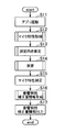
次に、上述した構成のスマートフォン1における音質補正動作を図5乃至図9のフローチャートを参照して説明する。これらのフローチャートは特に記載した場合を除きスマートフォン1の演算部13で実行される。
まず、ステップS11において、アプリを起動してステップS12に進む。ここで、アプリとは、本実施例にかかる音質補正方法を実行させる音声補正プログラムである。このアプリはスマートフォン1に予め或いはダウンロード等によりインストールされる。
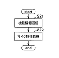
次に、特性情報取得工程としてのステップS12において、スマートフォン1のマイク特性をサーバ4から取得してステップS13に進む。本ステップでは、図6に示したように、まず、スマートフォン1が、予め設定されている機種情報を送信部12を介してサーバ4に送信する(ステップS21)。サーバ4では、受信部42が受信した機種情報に基づいて演算部43がマイク特性格納部44に格納されている当該機種のマイク特性を選択して、マイク特性情報として送信部41を介してスマートフォン1に送信する。スマートフォン1は、そのマイク特性情報を受信部11で受信することにより取得する(ステップS22)。なお、このステップS12は、一度実行すれば、例えば他の車両において補正動作を行う際など次回以降は実行しなくてもよい。
次に、ステップS13において、後述する測定動作のためにスマートフォン1の向きを確定させる。スマートフォン1の向きは、図7に示したフローチャートにより確定させる。
図7のフローチャートのステップS31において、スマートフォン1のユーザ等に、スマートフォン1の向きを指定してステップS32に進む。向きの指定は、例えば図10に示したような画面を車載機2の図示しない表示部やスマートフォン1の表示部17に表示させる。図10の例で下側とは、スマートフォン1の画面表示を基準として定めている。この向きの指定は、マイク特性情報を測定する際のスマートフォン1の向きと同じ向きを指定する。本実施例においては、スマートフォン1の向きを指定しているが、これは実質的にマイク15の向きを指定することと同等である。尚、例えば、実際に聴取するユーザの耳元(運転席、助手席を含む車両のシートのヘッドレストの位置に合わせること等)を示した画面を車載機2の図示しない表示部やスマートフォン1の表示部17に表示してもよい。
次に、ステップS32において、スマートフォン1の向きを推定してステップS33に進む。向きはスマートフォン1に搭載されているGセンサ18の出力(向き情報)に基づいて周知の方法により推定する。
次に、ステップS33において、スマートフォン1の実際の向きと指定した向きが一致したか否かを判断し、一致した場合(YESの場合)はステップS34に進み、一致しない場合(NOの場合)は一致するまで本ステップを繰り返す。
次に、ステップS34において、例えば図11に示したような画面により正しい向きであることを表示して図5のフローチャートに戻る。
図5のフローチャートに戻って、測定工程としてのステップS14において測定を行う。測定とは、車載機2が設置されている車室における当該車載機2による再生時の周波数特性を測定することである。測定動作は図8に示したフローチャートにより行われる。即ち、測定工程は、マイクの向き(スマートフォン1の向き)と、マイクの特性情報測定時のマイクの向き(指定した方向)と、に基づいて行われる。
図8のフローチャートのステップS41において、スマートフォン1の表示部17に測定開始ボタン等を表示して、そのボタンをユーザ等が操作することにより測定を開始してステップS42に進む。そしてユーザ等のボタン操作により、マイク15が集音する音声の録音を開始する。測定開始ボタンはスマートフォン1ではなく車載機2側に表示して、車載機2から測定開始を示す情報を受信するようにしてもよい。
次に、ステップS42において、ホワイトノイズ生成部14にホワイトノイズ音声を生成させホワイトノイズ音声情報として送信部12を介して送信させる。車載機2では、受信部22で受信したホワイトノイズ音声情報を直接再生部25で再生し、スピーカ3L及び3Rからホワイトノイズ音声を放射させる。このとき、車載機2側では補正部23による音質の補正動作を行わないようにする。スピーカ3L及び3Rから放射されたホワイトノイズ音声は、スマートフォン1のマイク15から集音されて録音部16に録音される。
次に、ステップS43において、所定時間ホワイトノイズ音声を車載機2に再生させた後に測定(録音)を終了させ、図5のフローチャートに戻る。つまり、ホワイトノイズ生成部14にホワイトノイズ音声の生成を停止させ、録音部16による録音を停止させる。そして、録音部16で録音されたホワイトノイズ音声が測定結果となる。図8のフローチャートの説明から明らかなように、演算部13は、Gセンサ18(向き情報取得部)が取得した向きに関する情報と、マイク15の特性情報測定時のマイクの向きが一致した場合に、車載機2(音響機器)に測定音を出力させ、マイク15を用いて測定音を測定する。
なお、本実施例では、スマートフォン1がホワイトノイズ生成部14を備えて、車載機2に対してホワイトノイズ音声を出力しているが、車載機2がホワイトノイズ音声等の測定音を生成する機能を備え、スマートフォン1は測定音の出力指示を送信するような構成であってもよい。
図5のフローチャートに戻って、ステップS15において、ステップS14で測定した測定結果に対してステップS12で取得したマイク特性情報に基づいて補正を行いステップS16に進む。本ステップで補正された測定結果がマイク補正情報となる。本ステップでは、ステップS14で行った測定に対して、マイク15の特性による影響を排除するために実行するものである。例えば、ステップS14で測定した測定結果を高速フーリエ変換して周波数特性を算出し、その周波数特性に対してマイク15の特性がフラットになるような補正を行う。
次に、補正情報生成工程としてのステップS16において、車載機2に対する音響特性補正量情報を生成してステップS17に進む。音響特性補正量情報生成動作は図9に示したフローチャートにより行われる。
図9のフローチャートのステップS51において、車載機2の補正部23から送信部21と受信部11を介して音響特性補正可能範囲情報(補正範囲に関する情報)を取得してステップS52に進む。音響特性補正可能情報とは、車載機2が有する補正部23の補正量に関する情報を示す。具体的には、イコライザ等の音質調整機能に関する情報であり、例えばバンド数、中心周波数 、Q値、ゲインの上限下限等の情報である。
次に、ステップS52において、ステップS51で取得した音響特性補正可能範囲情報と、ステップS15でマイク特性の補正がなされた後の測定結果(マイク補正情報)と、に基づいて車載機2に対する音響特性補正量情報を生成して図5のフローチャートに戻る。即ち、演算部13が、車載機2の出力音を補正する補正情報を、マイク15の特性及び測定結果に基づいて生成する補正情報生成部として機能する。
図5のフローチャートに戻って、ステップS17において、音響特性補正量情報を出力して終了する。本ステップでは、送信部12を介して音響特性補正量情報を車載機2に送信する。即ち、送信部12は、補正情報を車載機2(音響機器)に出力する出力部として機能する。車載機2では、受信部22が受信した音響特性補正量情報に基づいて補正部23が補正動作を行う。また、音響特性補正量情報を、スマートフォン1の表示部17に表示し、ユーザ等がマニュアルで車載機2の調整等を行ってもよい。
ここで、上述した測定動作と、マイク特性補正動作と、補正情報生成動作と、においての具体例を示して説明する。
図12は、ステップS14で測定(録音)されたままの状態の周波数特性の例である。図12では、200Hz以下が音声を拾いにくいマイク特性となっている。即ち、実際に鳴っている音よりも低音が小さく録音されてしまっている。従って、このままでは正しい補正ができない。
図13は、ステップS15でマイク特性の補正を行った結果の例である。この状態が実際の車室内の音の状況となる。但し、図13では、6kHz付近が大きく鳴ってしまう特性の車載機2(スピーカ3L及び3R)や車内環境であることが分かる。
そこで、ステップS16で車載機2の音響特性補正可能範囲情報に基づいてフラットな周波数特性に近づけるように音響特性補正量情報を生成し、車載機2に送信し、車載機2の補正部23が受信した音響特性補正量情報に基づいて図14に示すように補正する。図14の場合、6kHzを中心に-10dB、10kHzを中心に-5dB、2kHzを中心に+2dBする補正を行った。このようにすることにより、特性をフラットに近づけて聴感を良くすることができる。
本実施例によれば、スマートフォン1は車載機2とは別体に構成されており、受信部11でスマートフォン1のマイク15の特性情報をサーバ4から取得し、Gセンサ18でスマートフォン1の向きに関する情報を取得する。次に、演算部13がホワイトノイズ生成部14にホワイトノイズ音声を生成して車載機2に当該ホワイトノイズ音声を出力させ、マイク15を用いてホワイトノイズ音声を録音部16に録音させて測定結果とする。そして、演算部13でマイク15の特性情報と、測定結果と、に基づいて補正情報を生成する。このようにすることにより、スマートフォン1のマイクの特性を考慮して、補正情報を生成することができ、マイク15の特性に依存しないでカーオーディオ等の車載機2が設置された環境に適した出力音声に補正することができる。また、車載機2とは別体であるので、他の車両、他の音響機器等の複数の環境における補正をすることが容易にできる。
また、録音部16にホワイトノイズ音声を録音させた後にマイク特性補正や補正情報の生成を行っているので、処理能力の低くリアルタイム処理が困難な場合でも補正情報を生成することができる。
また、マイク15の特性や向きが取得できればマイク自体が高性能でなくてもよいので、スマートフォン1等の予めマイク15が設けられている機器を利用して容易にカーオーディオ等の音響機器の出力音を補正することができる。
また、演算部43は、Gセンサ18が取得したスマートフォン1の向きに関する情報と、マイク15の特性情報測定時のマイク15の向きが一致した場合に、車載機2にホワイトノイズ音声を出力させ、マイク15から録音している。このようにすることにより、マイク15の向きを考慮することができるので、よりマイク15の特性に依存しない補正を行うことができる。
また、演算部13は、マイク15の特性情報及びスマートフォン1の向きに関する情報に基づいて測定結果を補正したマイク補正情報を生成し、該マイク補正情報に基づいて補正情報を生成している。このようにすることにより、測定結果からマイク15の特性に依存しないマイク特性情報を生成し、その情報に基づいて車載機2が設置された環境に適した出力音声に補正することができる。
また、補正情報を車載機2に送信する送信部12を備えていている。このようにすることにより、生成された補正情報を車載機2が利用することで、以降は車載機2のみの構成で補正することができる。
また、受信部11が車載機2の音響特性補正可能範囲情報を取得し、演算部13は、受信部11が取得した音響特性補正可能範囲情報に基づいて補正情報を生成している。このようにすることにより、イコライザのバンド数、中心周波数 、Q値、ゲイン等の車載機2の音響特性補正可能範囲情報に基づいて補正情報を生成することができる。従って、スマートフォン1のみで複数の種類の車載機に最適な補正情報を生成することもできる。
また、サーバ4に機種ごとのマイク特性情報が格納されているので、新機種にも容易に対応することができ、また、マイク特性情報の更新等も容易にすることができる。
また、車載機2は自動車等の車両に設置されているので、設置された車両の音響特性に合わせた補正を行うことができる。
なお、上述した実施例では、車両に設置された音響機器として車載機2で説明したが、移動体であれば、鉄道車両や、船舶、航空機等に設置される音響機器であってもよい。また、屋内に設置される家庭用オーディオ機器等の音響機器であってもよい。
また、上述した実施例では、サーバ4を設けていたが、スマートフォン1にマイク15の特性情報が格納されていてもよい。
また、本発明は上記実施例に限定されるものではない。即ち、当業者は、従来公知の知見に従い、本発明の骨子を逸脱しない範囲で種々変形して実施することができる。かかる変形によってもなお本発明の音声補正装置の構成を具備する限り、勿論、本発明の範疇に含まれるものである。
1 スマートフォン(音声補正装置)
2 車載機(音響機器)
11 受信部(特性情報取得部、補正範囲情報取得部)
12 送信部(出力部)
13 演算部(補正情報生成部)
14 ホワイトノイズ生成部(測定部)
15 マイク
16 録音部(測定部)
18 Gセンサ(向き情報取得部)
S12 マイク特性取得(特性情報取得工程)
S13 測定向き確定(向き情報取得工程)
S14 測定(測定工程)
S15 マイク特性補正(補正情報生成工程)
S16 補正情報生成(補正情報生成工程)
2 車載機(音響機器)
11 受信部(特性情報取得部、補正範囲情報取得部)
12 送信部(出力部)
13 演算部(補正情報生成部)
14 ホワイトノイズ生成部(測定部)
15 マイク
16 録音部(測定部)
18 Gセンサ(向き情報取得部)
S12 マイク特性取得(特性情報取得工程)
S13 測定向き確定(向き情報取得工程)
S14 測定(測定工程)
S15 マイク特性補正(補正情報生成工程)
S16 補正情報生成(補正情報生成工程)
Claims (11)
- マイクを備え、音響機器の出力音を補正する補正情報を生成する音声補正装置であって、
前記音響機器に測定音を出力させ、前記マイクを介して前記測定音を測定する測定部と、
前記測定部が測定した測定結果に基づいて前記補正情報を生成する補正情報生成部と、
を備え、
前記音響機器とは別体に構成されている、
ことを特徴とする音声補正装置。 - 前記マイクの特性情報を取得する特性情報取得部を更に備え、
前記補正情報生成部は、前記特性情報取得部が取得した前記マイクの特性及び前記測定部が測定した測定結果に基づいて前記補正情報を生成する、
ことを特徴とする請求項1に記載の音声補正装置。 - 前記マイクの向きに関する情報を取得する向き情報取得部を更に備え、
前記測定部は、前記向き情報取得部が取得した前記向きに関する情報と、前記マイクの特性情報測定時の前記マイクの向きと、に基づいて、前記音響機器に測定音を出力させ、前記マイクを介して前記測定音を測定することを特徴とする請求項2に記載の音声補正装置。 - 前記補正情報生成部は、前記マイクの特性情報に基づいて前記測定部の測定結果を補正したマイク補正情報を生成し、該マイク補正情報に基づいて前記補正情報を生成することを特徴とする請求項3に記載の音声補正装置。
- 前記測定部は、前記測定音を録音し、
前記補正情報生成部は、前記測定部が録音した前記測定音に基づいて前記補正情報を生成する、
ことを特徴とする請求項1乃至4のうちいずれか一項に記載の音声補正装置。 - 前記補正情報を前記音響機器に出力する出力部を更に備えることを特徴とする請求項1乃至5のうちいずれか一項に記載の音声補正装置。
- 前記音響機器における補正範囲に関する情報を取得する補正範囲情報取得部を更に備え、
前記補正情報生成部は、前記補正範囲情報取得部が取得した前記補正範囲に関する情報に基づいて前記補正情報を生成する、
ことを特徴とする請求項1乃至6のうちいずれか一項に記載の音声補正装置。 - 前記音響機器は移動体に設けられていることを特徴とする請求項1乃至7のうちいずれか一項に記載の音声補正装置。
- 音響機器とは別体に構成されるとともにマイクを備え、該音響機器の出力音を補正する補正情報を生成する音声補正装置の音声補正方法であって、
前記音響機器に測定音を出力させ、前記マイクを介して前記測定音を測定する測定工程と、
前記特性情報取得工程で取得した前記マイクの特性及び前記測定工程で測定した測定結果に基づいて前記補正情報を生成する補正情報生成工程と、
を含むことを特徴とする音声補正方法。 - 請求項9に記載の音声補正方法を、コンピュータにより実行させることを特徴とする音声補正プログラム。
- 請求項10に記載の音声補正プログラムを格納したことを特徴とするコンピュータ読み取り可能な記録媒体。
Priority Applications (2)
| Application Number | Priority Date | Filing Date | Title |
|---|---|---|---|
| JP2017507183A JPWO2016151720A1 (ja) | 2015-03-23 | 2015-03-23 | 音声補正装置 |
| PCT/JP2015/058677 WO2016151720A1 (ja) | 2015-03-23 | 2015-03-23 | 音声補正装置 |
Applications Claiming Priority (1)
| Application Number | Priority Date | Filing Date | Title |
|---|---|---|---|
| PCT/JP2015/058677 WO2016151720A1 (ja) | 2015-03-23 | 2015-03-23 | 音声補正装置 |
Publications (1)
| Publication Number | Publication Date |
|---|---|
| WO2016151720A1 true WO2016151720A1 (ja) | 2016-09-29 |
Family
ID=56978815
Family Applications (1)
| Application Number | Title | Priority Date | Filing Date |
|---|---|---|---|
| PCT/JP2015/058677 Ceased WO2016151720A1 (ja) | 2015-03-23 | 2015-03-23 | 音声補正装置 |
Country Status (2)
| Country | Link |
|---|---|
| JP (1) | JPWO2016151720A1 (ja) |
| WO (1) | WO2016151720A1 (ja) |
Citations (3)
| Publication number | Priority date | Publication date | Assignee | Title |
|---|---|---|---|---|
| JP2006340285A (ja) * | 2005-06-06 | 2006-12-14 | Denso Corp | 車載装置、車載システム、車室内音場調整システムおよび携帯端末 |
| JP2013247456A (ja) * | 2012-05-24 | 2013-12-09 | Toshiba Corp | 音響処理装置、音響処理方法、音響処理プログラムおよび音響処理システム |
| JP2014165762A (ja) * | 2013-02-26 | 2014-09-08 | Nippon Telegr & Teleph Corp <Ntt> | 音量調整装置及び音量調整方法 |
Family Cites Families (1)
| Publication number | Priority date | Publication date | Assignee | Title |
|---|---|---|---|---|
| JP4985198B2 (ja) * | 2007-08-03 | 2012-07-25 | ヤマハ株式会社 | 測定用補助器具 |
-
2015
- 2015-03-23 JP JP2017507183A patent/JPWO2016151720A1/ja active Pending
- 2015-03-23 WO PCT/JP2015/058677 patent/WO2016151720A1/ja not_active Ceased
Patent Citations (3)
| Publication number | Priority date | Publication date | Assignee | Title |
|---|---|---|---|---|
| JP2006340285A (ja) * | 2005-06-06 | 2006-12-14 | Denso Corp | 車載装置、車載システム、車室内音場調整システムおよび携帯端末 |
| JP2013247456A (ja) * | 2012-05-24 | 2013-12-09 | Toshiba Corp | 音響処理装置、音響処理方法、音響処理プログラムおよび音響処理システム |
| JP2014165762A (ja) * | 2013-02-26 | 2014-09-08 | Nippon Telegr & Teleph Corp <Ntt> | 音量調整装置及び音量調整方法 |
Also Published As
| Publication number | Publication date |
|---|---|
| JPWO2016151720A1 (ja) | 2017-12-28 |
Similar Documents
| Publication | Publication Date | Title |
|---|---|---|
| JP2023052739A (ja) | 音声補正装置 | |
| CN104081789B (zh) | 耳机设备、终端设备、信息传送方法、程序和耳机系统 | |
| US20150124989A1 (en) | System for controlling vehicle interior sound using smart phone and method thereof | |
| US10002601B2 (en) | In-vehicle communication signal processing | |
| CN111526467B (zh) | 声学收听区域制图和频率校正 | |
| US10492044B2 (en) | Entertaining system of vehicle, method for connecting wireless, and processing sound using the same | |
| US20070036364A1 (en) | Sound field compensating apparatus and sound field compensating method | |
| JP2015022268A (ja) | オーディオ装置および音質調整方法 | |
| JP2019164357A (ja) | 端末装置、ヘッドホンシステム、ノイズキャンセルモードによる外部ヘッドホン制御方法 | |
| CN113179467A (zh) | 一种车辆环境音频处理方法、装置、设备及存储介质 | |
| JP2018045088A (ja) | ノイズ低減装置、音声認識システム、ノイズ低減方法、及びプログラム | |
| JP5932742B2 (ja) | 自動調整装置 | |
| JP2008245123A (ja) | 音場補正装置、音場補正方法及び制御プログラム | |
| JP2021164109A (ja) | 音場補正方法、音場補正プログラムおよび音場補正システム | |
| JP6536702B2 (ja) | 端末装置、ヘッドホンシステム | |
| WO2016151720A1 (ja) | 音声補正装置 | |
| JP2005352255A (ja) | 雑音消去装置、音響再生システム、および雑音消去方法 | |
| JP6281646B2 (ja) | 端末装置、ヘッドホンシステム | |
| JP6162488B2 (ja) | オーディオシステム及びスピーカモジュールの座標位置測定方法 | |
| JP2019033411A (ja) | 音場補正データ算出装置及び音場補正装置 | |
| JP2017061195A (ja) | 制御装置 | |
| JP2016220066A (ja) | 電子装置、電子システム、音声出力プログラムおよび音声出力方法 | |
| JP5181991B2 (ja) | 無線システムの自動音質測定方法及び音質測定装置 | |
| JP2012129692A (ja) | 携帯端末、オーディオデータ再生システム、オーディオデータ再生方法及びプログラム | |
| WO2011083610A1 (ja) | 車両用音響特性調整装置 |
Legal Events
| Date | Code | Title | Description |
|---|---|---|---|
| 121 | Ep: the epo has been informed by wipo that ep was designated in this application |
Ref document number: 15886275 Country of ref document: EP Kind code of ref document: A1 |
|
| ENP | Entry into the national phase |
Ref document number: 2017507183 Country of ref document: JP Kind code of ref document: A |
|
| NENP | Non-entry into the national phase |
Ref country code: DE |
|
| 122 | Ep: pct application non-entry in european phase |
Ref document number: 15886275 Country of ref document: EP Kind code of ref document: A1 |