WO2016148247A1 - 球状体の回転の測定装置、測定方法、ならびに、プログラム - Google Patents
球状体の回転の測定装置、測定方法、ならびに、プログラム Download PDFInfo
- Publication number
- WO2016148247A1 WO2016148247A1 PCT/JP2016/058545 JP2016058545W WO2016148247A1 WO 2016148247 A1 WO2016148247 A1 WO 2016148247A1 JP 2016058545 W JP2016058545 W JP 2016058545W WO 2016148247 A1 WO2016148247 A1 WO 2016148247A1
- Authority
- WO
- WIPO (PCT)
- Prior art keywords
- spherical body
- image
- clip
- template
- photographed
- Prior art date
- Legal status (The legal status is an assumption and is not a legal conclusion. Google has not performed a legal analysis and makes no representation as to the accuracy of the status listed.)
- Ceased
Links
Images






Classifications
-
- G—PHYSICS
- G06—COMPUTING OR CALCULATING; COUNTING
- G06V—IMAGE OR VIDEO RECOGNITION OR UNDERSTANDING
- G06V20/00—Scenes; Scene-specific elements
- G06V20/40—Scenes; Scene-specific elements in video content
-
- A—HUMAN NECESSITIES
- A63—SPORTS; GAMES; AMUSEMENTS
- A63B—APPARATUS FOR PHYSICAL TRAINING, GYMNASTICS, SWIMMING, CLIMBING, OR FENCING; BALL GAMES; TRAINING EQUIPMENT
- A63B24/00—Electric or electronic controls for exercising apparatus of preceding groups; Controlling or monitoring of exercises, sportive games, training or athletic performances
- A63B24/0003—Analysing the course of a movement or motion sequences during an exercise or trainings sequence, e.g. swing for golf or tennis
- A63B24/0006—Computerised comparison for qualitative assessment of motion sequences or the course of a movement
-
- A—HUMAN NECESSITIES
- A63—SPORTS; GAMES; AMUSEMENTS
- A63B—APPARATUS FOR PHYSICAL TRAINING, GYMNASTICS, SWIMMING, CLIMBING, OR FENCING; BALL GAMES; TRAINING EQUIPMENT
- A63B24/00—Electric or electronic controls for exercising apparatus of preceding groups; Controlling or monitoring of exercises, sportive games, training or athletic performances
- A63B24/0021—Tracking a path or terminating locations
-
- G—PHYSICS
- G01—MEASURING; TESTING
- G01P—MEASURING LINEAR OR ANGULAR SPEED, ACCELERATION, DECELERATION, OR SHOCK; INDICATING PRESENCE, ABSENCE, OR DIRECTION, OF MOVEMENT
- G01P3/00—Measuring linear or angular speed; Measuring differences of linear or angular speeds
- G01P3/36—Devices characterised by the use of optical means, e.g. using infrared, visible, or ultraviolet light
-
- G—PHYSICS
- G01—MEASURING; TESTING
- G01P—MEASURING LINEAR OR ANGULAR SPEED, ACCELERATION, DECELERATION, OR SHOCK; INDICATING PRESENCE, ABSENCE, OR DIRECTION, OF MOVEMENT
- G01P3/00—Measuring linear or angular speed; Measuring differences of linear or angular speeds
- G01P3/36—Devices characterised by the use of optical means, e.g. using infrared, visible, or ultraviolet light
- G01P3/38—Devices characterised by the use of optical means, e.g. using infrared, visible, or ultraviolet light using photographic means
-
- G—PHYSICS
- G01—MEASURING; TESTING
- G01P—MEASURING LINEAR OR ANGULAR SPEED, ACCELERATION, DECELERATION, OR SHOCK; INDICATING PRESENCE, ABSENCE, OR DIRECTION, OF MOVEMENT
- G01P3/00—Measuring linear or angular speed; Measuring differences of linear or angular speeds
- G01P3/42—Devices characterised by the use of electric or magnetic means
- G01P3/44—Devices characterised by the use of electric or magnetic means for measuring angular speed
-
- G—PHYSICS
- G06—COMPUTING OR CALCULATING; COUNTING
- G06F—ELECTRIC DIGITAL DATA PROCESSING
- G06F18/00—Pattern recognition
- G06F18/20—Analysing
- G06F18/22—Matching criteria, e.g. proximity measures
-
- G—PHYSICS
- G06—COMPUTING OR CALCULATING; COUNTING
- G06F—ELECTRIC DIGITAL DATA PROCESSING
- G06F18/00—Pattern recognition
- G06F18/20—Analysing
- G06F18/28—Determining representative reference patterns, e.g. by averaging or distorting; Generating dictionaries
-
- G—PHYSICS
- G06—COMPUTING OR CALCULATING; COUNTING
- G06T—IMAGE DATA PROCESSING OR GENERATION, IN GENERAL
- G06T7/00—Image analysis
- G06T7/10—Segmentation; Edge detection
- G06T7/12—Edge-based segmentation
-
- G—PHYSICS
- G06—COMPUTING OR CALCULATING; COUNTING
- G06T—IMAGE DATA PROCESSING OR GENERATION, IN GENERAL
- G06T7/00—Image analysis
- G06T7/20—Analysis of motion
- G06T7/246—Analysis of motion using feature-based methods, e.g. the tracking of corners or segments
- G06T7/248—Analysis of motion using feature-based methods, e.g. the tracking of corners or segments involving reference images or patches
-
- G—PHYSICS
- G06—COMPUTING OR CALCULATING; COUNTING
- G06T—IMAGE DATA PROCESSING OR GENERATION, IN GENERAL
- G06T7/00—Image analysis
- G06T7/20—Analysis of motion
- G06T7/262—Analysis of motion using transform domain methods, e.g. Fourier domain methods
-
- G—PHYSICS
- G06—COMPUTING OR CALCULATING; COUNTING
- G06V—IMAGE OR VIDEO RECOGNITION OR UNDERSTANDING
- G06V10/00—Arrangements for image or video recognition or understanding
- G06V10/70—Arrangements for image or video recognition or understanding using pattern recognition or machine learning
- G06V10/74—Image or video pattern matching; Proximity measures in feature spaces
- G06V10/75—Organisation of the matching processes, e.g. simultaneous or sequential comparisons of image or video features; Coarse-fine approaches, e.g. multi-scale approaches; using context analysis; Selection of dictionaries
- G06V10/751—Comparing pixel values or logical combinations thereof, or feature values having positional relevance, e.g. template matching
-
- G—PHYSICS
- G06—COMPUTING OR CALCULATING; COUNTING
- G06V—IMAGE OR VIDEO RECOGNITION OR UNDERSTANDING
- G06V10/00—Arrangements for image or video recognition or understanding
- G06V10/70—Arrangements for image or video recognition or understanding using pattern recognition or machine learning
- G06V10/77—Processing image or video features in feature spaces; using data integration or data reduction, e.g. principal component analysis [PCA] or independent component analysis [ICA] or self-organising maps [SOM]; Blind source separation
- G06V10/772—Determining representative reference patterns, e.g. averaging or distorting patterns; Generating dictionaries
-
- A—HUMAN NECESSITIES
- A63—SPORTS; GAMES; AMUSEMENTS
- A63B—APPARATUS FOR PHYSICAL TRAINING, GYMNASTICS, SWIMMING, CLIMBING, OR FENCING; BALL GAMES; TRAINING EQUIPMENT
- A63B2220/00—Measuring of physical parameters relating to sporting activity
- A63B2220/80—Special sensors, transducers or devices therefor
- A63B2220/806—Video cameras
-
- A—HUMAN NECESSITIES
- A63—SPORTS; GAMES; AMUSEMENTS
- A63B—APPARATUS FOR PHYSICAL TRAINING, GYMNASTICS, SWIMMING, CLIMBING, OR FENCING; BALL GAMES; TRAINING EQUIPMENT
- A63B2220/00—Measuring of physical parameters relating to sporting activity
- A63B2220/80—Special sensors, transducers or devices therefor
- A63B2220/807—Photo cameras
-
- G—PHYSICS
- G06—COMPUTING OR CALCULATING; COUNTING
- G06T—IMAGE DATA PROCESSING OR GENERATION, IN GENERAL
- G06T2207/00—Indexing scheme for image analysis or image enhancement
- G06T2207/10—Image acquisition modality
- G06T2207/10016—Video; Image sequence
-
- G—PHYSICS
- G06—COMPUTING OR CALCULATING; COUNTING
- G06T—IMAGE DATA PROCESSING OR GENERATION, IN GENERAL
- G06T2207/00—Indexing scheme for image analysis or image enhancement
- G06T2207/20—Special algorithmic details
- G06T2207/20048—Transform domain processing
- G06T2207/20052—Discrete cosine transform [DCT]
-
- G—PHYSICS
- G06—COMPUTING OR CALCULATING; COUNTING
- G06T—IMAGE DATA PROCESSING OR GENERATION, IN GENERAL
- G06T2207/00—Indexing scheme for image analysis or image enhancement
- G06T2207/20—Special algorithmic details
- G06T2207/20048—Transform domain processing
- G06T2207/20056—Discrete and fast Fourier transform, [DFT, FFT]
-
- G—PHYSICS
- G06—COMPUTING OR CALCULATING; COUNTING
- G06T—IMAGE DATA PROCESSING OR GENERATION, IN GENERAL
- G06T2207/00—Indexing scheme for image analysis or image enhancement
- G06T2207/20—Special algorithmic details
- G06T2207/20048—Transform domain processing
- G06T2207/20061—Hough transform
-
- G—PHYSICS
- G06—COMPUTING OR CALCULATING; COUNTING
- G06T—IMAGE DATA PROCESSING OR GENERATION, IN GENERAL
- G06T2207/00—Indexing scheme for image analysis or image enhancement
- G06T2207/30—Subject of image; Context of image processing
- G06T2207/30221—Sports video; Sports image
- G06T2207/30224—Ball; Puck
Definitions
- the present invention relates to a measuring device for measuring the rotation of a spherical body, a measuring method, and a program for realizing these by a computer.
- Patent Documents 1 and 2 Conventionally, techniques for measuring the rotation of a spherical body such as a ball have been proposed.
- a sensor is attached to the ball
- Patent Document 3 a ball with a marker attached is photographed with a camera. Information such as the direction of the axis is obtained.
- This invention solves the above subject, and it aims at providing the measuring apparatus which measures rotation of a spherical body, the measuring method, and the program for implement
- the measuring device is A circular shape in which the spherical body is photographed from one of a plurality of frames included in the moving picture in which the spherical body is photographed, or from a photographic image in which the spherical body is photographed under photographing conditions common to the photographing conditions of the moving picture.
- the template image is acquired,
- the center position and size of the spherical body are matched within a predetermined error range.
- the present invention it is possible to provide a measuring device and a measuring method for measuring the rotation of a spherical body, and a program for realizing these by a computer.
- the measurement apparatus is typically realized by a computer executing a program.
- the computer is connected to various output devices and input devices, and exchanges information with these devices.
- Programs executed on a computer can be distributed and sold by servers connected to the computer so that they can communicate with each other.
- CD-ROM Compact Disk Read Only Memory
- flash memory flash memory
- EEPROM Electrically Erasable Programmable ROM It is also possible to distribute, sell, etc. the information recording medium after recording it on a non-transitory information recording medium.
- the program is installed on a non-transitory information recording medium such as a hard disk, a solid state drive, a flash memory, an EEPROM, or the like that the computer has. Then, the information processing apparatus in the present embodiment is realized by the computer.
- a computer's CPU Central Processing Unit
- RAM Random Access Memory
- OS Operating System
- the information processing apparatus of the present embodiment can be configured using a dedicated electronic circuit instead of realizing the information processing apparatus of the present embodiment by a general-purpose computer.
- the program can be used as a material for generating a wiring diagram or timing chart of an electronic circuit.
- an electronic circuit that satisfies the specifications defined in the program is configured by an FPGA (Field Programmable Gate Array) or ASIC (Application Specific Integrated Circuit), and the electronic circuit has the functions defined in the program.
- the information processing apparatus of this embodiment is realized by functioning as a dedicated device.
- the measurement apparatus will be described assuming an aspect realized by a computer executing a program.
- FIG. 1 is an explanatory diagram showing a schematic configuration of a measuring apparatus according to an embodiment of the present invention.
- a description will be given with reference to FIG. 1
- the measuring apparatus 101 includes a template unit 102, a clip unit 103, a calculation unit 104, and an estimation unit 105.
- the template unit 102 from any of a plurality of frames included in the moving image in which the spherical body is photographed, or from the photographic image in which the spherical body is photographed under the photographing condition common to the photographing condition of the moving image, A template image is acquired by extracting a circular region where a spherical body is photographed.
- the template image may be extracted based on a user instruction or may be automatically extracted as will be described later.
- the video is taken with a high speed video camera.
- the moving image utilized in this embodiment assumes what was image
- the template image is an area including a circular area in which the spherical body is photographed from either one of the frames of the moving picture in which the spherical body is photographed or from a photographic image photographed under the photographing conditions common to the photographing conditions of the moving picture. Is extracted.
- FIG. 2 is an explanatory diagram showing an example of frames included in a moving image processed by the measurement apparatus according to the embodiment of the present invention. This figure is one of the frames included in a video shot with a high-speed video camera from a baseball pitcher about 20m diagonally behind a baseball pitcher throwing a ball.
- FIG. 3 is an explanatory diagram showing an example of a template image acquired by the measuring apparatus according to the embodiment of the present invention.
- a template image is one of the frames of a moving image. Therefore, an image obtained by cutting out a square area on which a spherical body is drawn is used as it is.
- a template image is extracted from a moving image to be processed or a photographic image shot under common shooting conditions.
- the template image of the present embodiment has other frames in the moving image and the surrounding environment where the image is taken, for example, conditions such as background brightness, lighting direction, brightness, hue, camera definition, and aperture amount. Since they are in line, measurement can be performed with high accuracy.
- conditions such as background brightness, lighting direction, brightness, hue, camera definition, and aperture amount. Since they are in line, measurement can be performed with high accuracy.
- the shooting conditions are common can be determined, for example, based on whether or not the above-described various conditions match, but which conditions are used can be determined through experiments or the like.
- a photographic image may adopt one frame in another video shot under a common shooting condition, or a template image extracted from another video shot under a common shooting condition as it is, It is good also as a template image used for the process of this moving image.
- the clip unit 103 extracts a plurality of similar regions that are similar to the acquired template image from each of the plurality of frames, and expands / contracts the center position and size of the spherical body within a predetermined error range.
- a series of clip images in which spherical bodies are drawn so as to coincide with each other is acquired.
- the measurement apparatus 101 obtains a plurality of clip images in which spherical bodies are drawn with the same size and their centers are common by applying an Hough transform for detecting a circle to appropriately move and scale the image. .
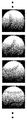
- FIG. 4 is an explanatory diagram showing an example of a clip image acquired by the measurement apparatus according to the embodiment of the present invention.
- the clip images are represented by squares having the same size, and the positions and sizes at which the spherical bodies are drawn in the squares are aligned.
- the calculation unit 104 calculates the similarity between the plurality of clip images, and obtains a matrix in which the calculated similarity is arranged in the shooting order of the frames from which the plurality of clip images are extracted.
- FIG. 5 is an explanatory diagram showing a matrix representing the degree of similarity acquired by the measurement apparatus according to the embodiment of the present invention.
- each element of the similarity matrix is represented by black and white shading.
- Each element of the similarity degree matrix represents the similarity degree between the clip image with the number of rows and the clip image with the number of columns.
- the degree of similarity representing how much the clip images differ may be used, or the degree of similarity representing how similar the clip images may be utilized.
- the degree of difference for example, a weighted average or a weighted sum of differences between pixels can be employed.
- the similarity for example, a cosine of an angle formed by a vector composed of pixel values of each pixel (inner product of vector direction vectors in which pixel values are arranged) can be employed.
- the estimation unit 105 estimates the rotational speed of the spherical body from the distribution of elements in the calculated similarity degree matrix. After the rotation speed is estimated, it is also possible to estimate the rotation axis by applying similarities between clip moving images and techniques relating to perspective projection and rotation in a three-dimensional space. Details of the estimation of the rotation axis will be described later.
- the rotation information it is possible to estimate the rotation number (rotation speed) per unit time, the rotation cycle, the direction of the rotation axis, and the like.
- processing in each of the above parts is executed by a computer CPU, an image processor, a dedicated electronic circuit, or the like.
- Various moving images and images to be processed are stored in a storage device such as a RAM, a hard disk, or a solid state drive.
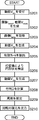
- FIG. 11 is a flowchart showing the procedure of the measurement method executed by the measurement apparatus according to the embodiment of the present invention. Hereinafter, the processing executed by the measuring apparatus 101 will be described in detail.
- the measuring apparatus 101 receives a moving image to be processed (step S201).
- the moving image is a photograph of a spherical body.
- a high-speed video camera can be used to analyze the rotation of the spherical body with high accuracy. Based on the sampling theorem, it is necessary to photograph the spherical body at a frame rate that is at least twice the desired rotational speed. According to experiments, favorable results have been obtained by shooting at a frame rate of about 10 times the assumed rotational speed of the spherical body.
- V src the input moving image to be processed accepted in step S201 is denoted as V src .
- pixels in the horizontal direction u (1 ⁇ u ⁇ W (V)) and vertical direction v (1 ⁇ v ⁇ H (V)) of the t (1 ⁇ t ⁇ N (V)) th frame of the video V The pixel value at the position is expressed as V (u, v, t).
- a value obtained by dividing t by the frame rate corresponds to the actual time elapsed, and a value obtained by dividing N (V) by the frame rate corresponds to the shooting time length of the moving image V.
- W (V) and H (V) are values representing the width and height of each frame of the moving image V in units of pixels.
- N N (V src )
- W W (V src )
- H H (V src )
- the measuring apparatus 101 generates an average image I mean and a mask moving image V mask from the input moving image V src (step S202).
- the mask video V mask is a differential video that has been converted to monochrome by removing the image corresponding to the background from the input video V src and can be defined as follows.
- V mask (u, v, t) 0, if diff (V src (u, v, t), I mean (u, v)) ⁇ BK thresh ;
- V mask (u, v, t) 1, otherwise
- diff (p, q) is an operation for obtaining a difference between the pixel values p and q. If p and q are pixels of a grayscale image, the absolute value of the difference between the pixel values may be calculated. When p and q are pixels of a color image, the sum of squares of differences between elements or the square root thereof may be calculated. Alternatively, the diff () for the grayscale image may be applied after applying a variety of filters to the color image to make it grayscale. In the following, in order to facilitate understanding, a gray scale moving image in which each pixel value is between 0 and 255 will be used as the input moving image V src .
- BK thresh is a threshold value.
- a numerical value of about 12-15 can be applied, but the value can be changed as appropriate.
- the template unit 102 of the measuring apparatus 101 when the mask video V mask is obtained from the input video V src, the template unit 102 of the measuring apparatus 101 generates the template image I temp based on a user instruction or automatically with reference to these pieces of information.
- the template image I temp is an image having a width and height of 2 ⁇ R + 1 obtained by extracting a square area in which a spherical body is drawn from any frame of the input moving image.
- R represents the radius at which the spherical body is drawn in the frame expressed by the number of pixels.
- the pixels of the original frame may be maintained as they are, or a predetermined color different from the color assumed for the transparent color or the spherical body is arranged. May be.
- the template image I temp may be acquired from the input moving image V src based on an instruction of a user who performs processing, but can also be automatically extracted by a method disclosed in an embodiment described later.
- the measuring apparatus 101 refers to the input moving image V src , the mask moving image V mask , and the template image I temp to generate a match moving image V tm (step S204).
- the match video V tm is defined as follows.
- K (u, v, t)
- V tm (u, v, t)
- the measuring apparatus 101 extracts an effective frame, that is, a frame in which a spherical body is captured (step S205). This assumes a situation in which a spherical body enters the screen from the outside of the screen or goes out of the screen from the inside of the screen.
- the measurement apparatus 101 sets an appropriate threshold value TM thresh, and the maximum value of the pixel value of each frame V tm (u, v, t) max 1 ⁇ u ⁇ W max 1 ⁇ v ⁇ H V tm (u, v, t) Calculate
- the measuring apparatus 101 has max 1 ⁇ u ⁇ W max 1 ⁇ v ⁇ H V tm (u, v, S + 1) for frame numbers S + 1, S + 2,..., S + N ′. ) ⁇ TM thresh ; max 1 ⁇ u ⁇ W max 1 ⁇ v ⁇ H V tm (u, v, S + 2) ⁇ TM thresh ; ...; max 1 ⁇ u ⁇ W max 1 ⁇ v ⁇ H V tm (u, v, S + N ') ⁇ TM thresh Among consecutive frames satisfying, a frame having the maximum N ′ is searched. As a result, when the spherical body once goes out of the screen and enters the screen again, the longer continuous frame is selected.
- S + 1 is the first frame number in which the spherical body is photographed in the frame
- N ′ represents the time length in which the spherical body is photographed in the frame by the number of frames.
- the center of the spherical body is drawn at the position (x tm (t), y tm (t)).
- a shift of several pixels occurs due to calculation errors and sampling errors.
- the size of the spherical body drawn in the moving image also changes.
- the measuring apparatus 101 detects each circular shape by using the Hough transform.
- a boundary pixel whose pixel value is a boundary between 0 and non-zero is extracted, and a circle that best fits the boundary pixel is detected by Hough transform (step S206).
- each mask movie V mask There is no need to apply the Hough transform to the entire frame. If the area to be applied is only around (x tm (t), y tm (t)), the calculation time can be greatly reduced.
- Hough transform may be applied under the restriction of belonging.
- the upper limit of r (t) may be left as R if it is extracted from a frame in which a spherical body is drawn as large as possible.
- the clip unit 103 of the measuring device 101 can input the input video V src Clip the circle area with the center position (x (t), y (t)) and radius r (t) from the frame number S + 1, S + 2, ..., S + N ' Is expanded / reduced to a circle with a diameter of 2 ⁇ R + 1, thereby generating a clip video V clip consisting of a square frame with a width and height of 2 ⁇ R + 1 (step S207).
- V clip (u, v, t) V src ((uR-1) / E (t) + x (t), (vR-1) / E (t) + y (t), t + S)
- a circular background pixel may have a pixel value of 0, or the pixel value of the original image may be used as it is, as in the above equation.
- various smoothing processes may be applied. For example, Gaussian smoothing having a kernel with a standard deviation of about 2 pixels can be applied. In this way, a clip image as shown in FIG. 4 is obtained.
- the calculating unit 104 calculates a matrix D representing the similarity between frames as follows (step S208).
- the subscripts i and j represent elements of i rows and j columns in the matrix.
- G ⁇ (uR ⁇ 1, vR ⁇ 1) is a weight based on a two-dimensional Gaussian distribution that is symmetric about the center of each frame of the clip moving image.
- G ⁇ (uR-1, vR-1) exp (-((uR-1) 2 + (vR-1) 2 ] / (2 ⁇ ⁇ 2 ]) That is, the spherical body is photographed more clearly and accurately near the center than near the periphery. Therefore, the weight near the center is increased.
- ⁇ representing the spread of the Gaussian distribution
- a constant such as (2 ⁇ R + 1) / 6 can be adopted.
- the values of each element of the matrix D are expressed by shading, and the shading appears as a diagonal stripe pattern.
- the estimation unit 105 of the measurement apparatus 101 estimates the specifications of the rotation of the spherical body from the distribution of elements of the matrix (step S209).
- a method for obtaining the rotation period will be described.
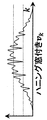
- FIG. 6 is an explanatory diagram showing the dissimilarity graph v k acquired by the measuring apparatus according to the embodiment of the present invention.
- v k represents the change in the average element when the matrix D is viewed from the diagonal axis direction, and values with small differences appear at substantially regular intervals. Recognize.
- This interval corresponds to the number of frames required for one rotation of the spherical body.
- the number of frames required for one rotation of the spherical body that is, the above-described interval is expressed as a cycle T of v k .
- the first method uses discrete cosine transform.
- FIG. 7 is an explanatory diagram showing the obtained dissimilarity graph w k (Hanning windowed dissimilarity graph v k) by the measuring device according to an embodiment of the present invention.
- FIG. 8 is an explanatory diagram showing a result C k of the discrete cosine transform in the measurement apparatus according to the embodiment of the present invention.
- the sequence C k is obtained by performing the discrete cosine transform.
- the second method uses a discrete Fourier transform. That is, the following discrete Fourier transform is performed on the sequence w k .
- FIG. 9 is an explanatory diagram showing the power spectrum of the result Pk of the discrete Fourier transform in the measurement apparatus according to the embodiment of the present invention.
- a complex sequence P k is obtained by discrete Fourier transform.
- T M / k *
- the third method uses an average amplitude difference function.
- the average amplitude difference function a k represents a difference between v i and v i + k obtained by shifting this by k.
- the interval between striped patterns (the period of change in the average value of similarity degrees between clip images having the same difference in shooting order) T is estimated by a plurality of methods. If the same value T is obtained for all methods, this means that the accuracy as a measurement result of the rotation period is high.
- the periods obtained by a plurality of methods may be different. Typically, it is a situation where a value twice as large as a value obtained by a certain method or a value shifted by 0.5 to 1 from a value obtained by a certain method can be obtained by another method. In such a case, it is possible to determine which is the estimated value by majority vote, or to let the user select which is correct.
- T 1 argmin 0 + T / 2 ⁇ k ⁇ (1 + T / 2) v k ;
- T 2 argmin 1 + T / 2 ⁇ k ⁇ (2 + T / 2) v k ;
- T 3 argmin 2 + T / 2 ⁇ k ⁇ (3 + T / 2) v k ;
- T L argmin L-1 + T / 2 ⁇ k ⁇ (L + T / 2) v k
- L is a maximum value satisfying L + T / 2 ⁇ N ′.
- T * (T L -T 1 ) / (L-1)
- the obtained period T * corresponds to the number of frames required for one rotation of the spherical body. Therefore, the estimated value of the rotation period of the spherical body is obtained by dividing T * by the frame rate.
- the rotational speed (rotational speed) of the spherical body is the reciprocal of the rotational period of the spherical body.
- a set A of unit vectors a 1 , a 2 ,..., A Z representing axial direction candidates of the rotation axis is prepared. Since it is desirable that the candidate unit vectors be as equally spaced as possible, they may be generated from the vertices of a regular polyhedron or a quasi-regular polyhedron, or generated by generating random numbers.
- the average image J mean of the clip video V clip is obtained in the same manner as the average image I mean of the input video V src .
- a ball video V ball is created by subtracting the average image J mean from the clip video V clip .
- V ball (u, v, t) V clip (u, v, t) -J mean (u, v)
- the estimation of the rotation axis is considered as follows. That is, if the axis of rotation of the sphere coincides with direction a, (1) From the frame of the ball video V ball frame number t, a transformation f for projecting each pixel of the ball video to the hemisphere is performed, (2) After rotating the hemisphere about k ⁇ ⁇ 0 around the rotation axis in direction a, (3) An image obtained by projecting the rotated hemisphere onto a plane should substantially coincide with the frame of the ball animation V ball with the frame number t + k.
- f (u, v) ((uR-1) / R, (vR-1) / R, (1-((uR-1) / R) 2 -((vR-1) / R) 2 ] 1 / 2 );
- f -1 (x, y, z) (x ⁇ R + R + 1, y ⁇ R + R + 1);
- (u ', v') f -1 ( ⁇ (a, k ⁇ ⁇ 0 ) f (u, v))
- ⁇ (a, k ⁇ ⁇ 0 ) is a rotation matrix representing rotation of an angle k ⁇ ⁇ 0 around the rotation axis in the direction a.
- hemispherical and plane conversion assumes parallel projection.
- an evaluation function E (a) for the rotation axis in the direction a is determined as follows, for example.
- the evaluation function E (a) may be determined as follows.
- E (a) since the coefficient is calculated using the position before and after rotation, the coefficient depends on the rotation axis a and a denominator for normalization is required. .
- an estimated value a * of the rotation axis of the spherical body is obtained as follows.
- the measuring apparatus 101 outputs an estimated value of the rotation specifications (step S210). This process is terminated.
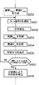
- FIG. 12 is a flowchart showing a procedure for automatically acquiring a template image executed by the measurement apparatus according to the embodiment of the present invention.
- step S202 an appropriate frame (frame number B) is selected from the mask moving image V mask (step S401), and the boundary pixels of the pixel values 0 and 1 in the frame are circled.
- the best fitting circle is detected by applying the Hough transform for detection (step S402).
- the application range of the Hough transform here is the entire frame.
- the diameter of the circle for detection may be about 0.5 to 2 times the diameter in a typical frame when the spherical body is photographed by the camera. This range can be changed as appropriate.
- the narrowing may be performed before applying the Hough transform. That is, select all the polygons whose sides are the boundary between the pixel value 0 and the pixel value 1, or select a polygon having the same width and height (for example, a range of 0.8 times to 1.25 times).
- the Hough transform is applied to the square, and the most suitable circle may be used as the detection result.
- a circle detection method other than the Hough transform or a substantially square detection method may be employed.
- a template image I temp is extracted based on this (step S203).
- step S403 Whether or not N ′ is sufficiently long can be determined, for example, based on whether or not the ratio of N ′ to N is equal to or greater than a threshold (for example, 1/3, 1/4, etc.).
- step S403 If N ′ is too short or the frame number B is not included (step S403; No), it means that the frame number B selected for template extraction is not appropriate. In this case, the frame number is selected again and the template image is extracted again. If the frame number B is appropriate (step S403; Yes), the process proceeds to step S206 and subsequent steps.
- the order of selecting the frame number to be selected first may be regularly determined as follows. For example, if the total number of frames is N, N / 2, N / 3, 2 ⁇ N / 3, N / 4, 2 ⁇ N / 4, 3 ⁇ N / 4, N / 5, 2 ⁇ N / 5, 3 ⁇ N / 5, 4 ⁇ N / 5, ... As described above, it is possible to adopt a method such as reselecting the frame number in order.
- a photographic image may be adopted instead of the frame of frame number B.
- a plurality of frames are selected at random from the input video V src . Then, the center and radius of the circle are detected by applying the Hough transform to each selected frame in the same manner as described above.
- a template candidate is created by extracting a circular region from the frame in which the ellipse is detected based on the center and radius of the detected circle.
- the template candidates are presented to the user, and the user is allowed to select a template image I temp in which the spherical body is clearly photographed among the template candidates.
- ⁇ ⁇ This technique can also be applied to automatic extraction. For example, image parameters such as contrast, clarity, and radius of a circular area are calculated for each template candidate. Then, based on the calculated image parameter value, the template candidates are classified into several (for example, about 3 to 5) clusters. One or more image parameters may be adopted for cluster classification. For cluster classification, for example, known techniques such as k-means and x-means can be applied.
- template candidate is classified in the template candidates having the best image parameters is selected as a template image I temp. This is because an image classified into a cluster having a small number of elements is considered to have a high possibility of noise and erroneous detection.
- the following method can also be adopted. First, an average of all candidate image parameters is obtained. Next, the degree of separation indicating how far each candidate image parameter is from the average is calculated, and the candidates are sorted in ascending order of the degree of separation.
- ⁇ may be a constant of about 2 to 5, and a candidate located at a rank of 1 / ⁇ from the top may be selected as the template image I temp .
- This method is a method that does not deviate greatly from the average and selects a reasonably good candidate.
- the candidates when the template candidates are presented and selected by the user, the candidates can be arranged and presented in ascending order of the separation degree used here. Candidates with a large degree of separation are highly likely to be noise or misdetection, and therefore, the user can easily select a template image by lowering the order of presentation.
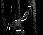
- FIG. 13 is an explanatory diagram illustrating an example of frames included in a moving image shot outdoors that is processed by the measurement apparatus according to the embodiment of the present invention.
- the right arm of the pitcher is photographed from the lower left corner of the image toward the center, and the ball is photographed at the upper center of the image.
- the crescent-shaped highlight On the upper side of the photographed ball, there is a crescent-shaped highlight.
- the highlight portion is generated when light emitted from illumination including the sun is reflected with high intensity, reaches the camera as it is, and saturation occurs in the photographing element.
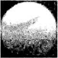
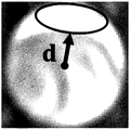
- FIG. 14 is an explanatory diagram showing the highlight direction of a spherical body photographed in a clip image.
- a portion surrounded by an ellipse above the ball photographed in the clip image is a central region of the highlight portion.
- the highlight direction d is a direction from the center of the ball toward the center area of the highlight portion.
- the highlight direction d may be explicitly specified by a user who performs measurement, or may be automatically detected.
- various known techniques can be adopted, but in this embodiment, (1) Since the illumination is above, the highlight portion appears in a crescent or elliptical shape above the ball. (2) In any clip image, highlight portions appear at substantially the same position and direction. it is conceivable that.
- the brightness is expressed in 256 levels from 0 to 255.
- a pixel position (u, v) whose lightness exceeds a predetermined threshold value for example, any positive constant of 250-255 is obtained, and its barycentric position is calculated.
- the center-of-gravity position is the center of the highlight portion.
- pixels having an average brightness H (u, v) equal to or greater than a predetermined area (for example, 20% of the shooting area of the ball) and greater than or equal to the threshold value are spread around the obtained center of gravity position. Find out. This spread represents the size of the highlight portion.
- the highlight direction d is set to the direction of the center of gravity obtained from the center of the clip image. If the area of the highlight portion is small, the following highlight portion omission processing may not be executed.
- the two-dimensional Gaussian distribution G ⁇ (uR-1, vR-1) is used as the weight, but the area of the highlight portion is sufficiently large.
- G ⁇ (uR-1, vR -1) may be weighted as follows.
- the above weighting function G ⁇ (x, y) G ⁇ (uR-1, vR-1 )
- M (x, y) 0, if x 2 + y 2 > R 2 or (x, y) ⁇ d>0;
- M (x, y) G ⁇ (x, y), otherwise
- condition “x 2 + y 2 > R 2 ” means that the information photographed outside the ball in the clip image is ignored in the calculation of the similarity matrix Di , j . This condition can be adopted even when the area of the highlight portion is sufficiently small or does not exist.
- the measuring device in the present embodiment is A circular shape in which the spherical body is photographed from one of a plurality of frames included in the moving picture in which the spherical body is photographed, or from a photographic image in which the spherical body is photographed under photographing conditions common to the photographing conditions of the moving picture.
- a template part that acquires a template image by extracting an area By extracting and enlarging / reducing a plurality of similar regions respectively similar to the acquired template image from each of the plurality of frames, the center position and size of the spherical body are matched within a predetermined error range.
- the estimation unit obtains an average value of similarity levels between clip images having the same difference in shooting order from the distribution of elements in the similarity level matrix, and the period of change of the average value with respect to the difference in shooting order is different. If the estimation is performed by a plurality of methods and the periods estimated by the plurality of methods coincide with each other, the coincident period can be estimated as the rotation period of the spherical body.
- the plurality of methods can be configured to include a method based on a discrete cosine transform, a method based on a discrete Fourier transform, and a method based on an average amplitude difference function.
- the template unit obtains a differential video between the video and the average image of the plurality of frames, detects a circular area drawn on the differential video, and detects the size and position of the detected circular area Can be configured to identify a circular region that continuously changes over time, and to extract the template image from the identified circular region.
- the template part and the clip part can be configured to extract the circular region and the plurality of similar regions by Hough transform.
- the estimator rotates the spherical body by minimizing a difference between the plurality of hypothetical images obtained by assuming that the spherical body rotates around a rotation axis candidate and the plurality of clip images. It can be configured to estimate the axis of rotation.
- the measurement method of this embodiment is The measuring device captures the spherical body from one of a plurality of frames included in the moving image in which the spherical body is photographed or from a photographic image in which the spherical body is photographed under photographing conditions common to the photographing conditions of the moving image.
- a template step of obtaining a template image by extracting the circular region that has been made The measurement apparatus extracts a plurality of similar regions similar to the acquired template image from each of the plurality of frames and expands / contracts the center position and size of the spherical body within a predetermined error range.
- the measuring apparatus includes an estimating step of estimating rotation of the spherical body from a distribution of elements in the calculated similarity degree matrix.
- the program of this embodiment is a computer, A circular shape in which the spherical body is photographed from one of a plurality of frames included in the moving picture in which the spherical body is photographed, or from a photographic image in which the spherical body is photographed under photographing conditions common to the photographing conditions of the moving picture.
- a template part that acquires a template image by extracting an area By extracting and enlarging / reducing a plurality of similar regions respectively similar to the acquired template image from each of the plurality of frames, the center position and size of the spherical body are matched within a predetermined error range.
- a clip unit for obtaining a plurality of clip images in which the spherical body is drawn A calculation unit that calculates the similarity between the plurality of clip images and obtains a matrix in which the calculated similarity is arranged in the shooting order of the frames from which the plurality of clip images are extracted, It functions as an estimation unit for estimating the rotation of the spherical body from the distribution of elements in the calculated similarity degree matrix.
- the present invention it is possible to provide a measuring device and a measuring method for measuring the rotation of a spherical body, and a program for realizing these by a computer.
Landscapes
- Engineering & Computer Science (AREA)
- Physics & Mathematics (AREA)
- Theoretical Computer Science (AREA)
- General Physics & Mathematics (AREA)
- Computer Vision & Pattern Recognition (AREA)
- Multimedia (AREA)
- Health & Medical Sciences (AREA)
- General Health & Medical Sciences (AREA)
- Evolutionary Computation (AREA)
- Artificial Intelligence (AREA)
- Data Mining & Analysis (AREA)
- Databases & Information Systems (AREA)
- Computing Systems (AREA)
- Medical Informatics (AREA)
- Software Systems (AREA)
- Electromagnetism (AREA)
- Power Engineering (AREA)
- Physical Education & Sports Medicine (AREA)
- Bioinformatics & Computational Biology (AREA)
- Mathematical Physics (AREA)
- Bioinformatics & Cheminformatics (AREA)
- Life Sciences & Earth Sciences (AREA)
- Evolutionary Biology (AREA)
- General Engineering & Computer Science (AREA)
- Image Analysis (AREA)
Abstract
Description
球状体が撮影された動画に含まれる複数のフレームのいずれか、もしくは、当該動画の撮影条件と共通する撮影条件により当該球状体が撮影された写真画像から、当該球状体が撮影された円状領域を抽出することにより、テンプレート画像を取得し、
前記複数のフレームのそれぞれから、前記取得されたテンプレート画像にそれぞれ類似する複数の類似領域を抽出して拡縮することにより、前記球状体の中心位置および大きさが所定の誤差範囲内で一致するように前記球状体が描画された複数のクリップ画像を取得し、
前記複数のクリップ画像同士の類否度を算定して、当該算定された類否度を当該複数のクリップ画像同士が抽出されたフレームの撮影順に並べた行列を取得し、
前記算定された類否度の行列における要素の分布から、前記球状体の回転を推定する。
本実施形態に係る測定装置は、典型的には、プログラムをコンピュータが実行することによって実現される。当該コンピュータは、各種の出力装置や入力装置に接続され、これらの機器と情報を送受する。
N = N(Vsrc), W = W(Vsrc), H = H(Vsrc)
のように略記する。
Imean(u,v) = Σt=1 N Vsrc(u,v,t)/N
Vmask(u,v,t) = 0, if diff(Vsrc(u,v,t), Imean(u,v)) < BKthresh;
Vmask(u,v,t) = 1, otherwise
K(u,v,t) = Σi=-R R Σj=-R R 〔Vsrc(u+i,v+j,t) - Itemp(i+R+1,j+R+1)〕2;
Vtm(u,v,t) = 0, if Vmask(u,v,t) = 0;
Vtm(u,v,t) = exp(-〔K(u,v,t)〕2), if Vmask(u,v,t) ≠ 0
なお、テンプレート画像Itempの背景を無視することも可能である。すなわち、
K(u,v,t) = Σi=-R R Σj=-R R fn(i,j,t)2;
fn(i,j,t) = Vsrc(u+i,v+j,t) - Itemp(i+R+1,j+R+1),
if (i+R+1)2+(j+R+1)2≦(R+1)2;
fn(i,j,t) = 0, otherwise
とするのである。これは、テンプレート画像の形状として円形を採用したことに相当する。
max1≦u≦W max1≦v≦H Vtm(u,v,t)
を計算する。
max1≦u≦W max1≦v≦H Vtm(u,v,S+1)≧TMthresh;
max1≦u≦W max1≦v≦H Vtm(u,v,S+2)≧TMthresh;
...;
max1≦u≦W max1≦v≦H Vtm(u,v,S+N')≧TMthresh
を満たす連続フレームのうち、N'が最大となるものを探す。これにより、球状体が一旦画面の外に出て、再度画面内に入ってきたときには、長い方の連続フレームが選ばれることになる。
(xtm(t),ytm(t) = argmax(u,v) | 1≦u≦W, 1≦v≦H Vtm(u,v,t)
のように定義できる。すなわち、フレーム内の画素値の最大値を有する画素を探し、その画素位置を取得すれば良い。
0.5×R ≦ r(t) ≦ R;
xtm(t)-0.5×R ≦ x(t) ≦ xtm(t)+0.5×R;
ytm(t)-0.5×R ≦ y(t) ≦ ytm(t)+0.5×R
なお、球状体が次第にカメラに近付くような向きで撮影を行った場合、たとえば、キャッチャーの背後からピッチャー方向にボールを撮影した場合には、r(t)の上限は、1.5×Rや2×R等、適宜状況に応じて、検索範囲を広げることが可能である。
E(t) = R/r(t)
あるいは
E(t) = (2×R+1)/(2×r(t))
で拡縮した後、原点が(R+1,R+1)へ移動するように座標変換すれば、クリップ動画Vclipのフレーム番号tのフレームが得られる。拡縮率が2通りあるのは、周囲の1ドットを含めるか否かの違いであり、いずれを選択するかは任意である。さて、クリップ動画Vclipと入力動画Vsrcの画素値の最も単純な対応関係は、以下の通りである。
Vclip(u,v,t) = Vsrc((u-R-1)/E(t)+x(t), (v-R-1)/E(t)+y(t), t+S)
クリップ動画Vclip(u,v,t)においては、1≦u≦2×R+1, 1≦v≦2×R+1, 1≦t≦N' が、有効な範囲である。すなわち、
H(Vclip) = W(Vclip) = 2×R+1;
N(Vclip) = N'
Di,j = Σu=1 2×R+1 Σv=1 2×R+1
Gσ(u-R-1,v-R-1)×〔Vclip(u,v,i) - Vclip(u,v,j)〕2
Gσ(u-R-1,v-R-1) = exp(-〔(u-R-1)2+(v-R-1)2〕/〔2×σ2〕)
すなわち、球状体は、周縁付近に比べて中心付近の方が綺麗に精度良く撮影されている。そこで、中心付近の重み付けを大きくするのである。ガウス分布の広がりを表す標準偏差σとしては、たとえば、(2×R+1)/6などの定数を採用することができる。
vk = Σi=1 N'/3 Di,i+k
Ck = Σn=1 M wn×cos〔π×k×(2×n+1)/(2×M)〕;
wk = C1/2 + Σn=2 M Cn×cos〔π×n×(2×k+1)/(2×M)〕
T = 2×M/k* - 0.5
Pf = (1/M)×Σn=1 M wn×exp(-i×2×π×k×n/M)
T = M/k*
ak = 1/〔M-k〕×Σi=1 M-k |vi - vi+k|
平均振幅差関数akは、viと、これをkだけずらしたvi+kとの差分を表すものである。
T = k*
T1 = argmin0+T/2≦k<(1+T/2) vk;
T2 = argmin1+T/2≦k<(2+T/2) vk;
T3 = argmin2+T/2≦k<(3+T/2) vk;
...;
TL = argminL-1+T/2≦k<(L+T/2) vk
ただし、Lは、L+T/2≦N'を満たす最大値とする。
T* = (TL-T1)/(L-1)
ここで、得られた周期T*は、球状体の一回転にかかるフレーム数に相当する。したがって、球状体の回転周期の推測値は、T*をフレームレートで除算することによって得られる。また、球状体の回転数(回転速度)は、球状体の回転周期の逆数である。
Jmean(u,v) = Σt=1 N' Vclip(u,v,t)/N';
Vball(u,v,t) = Vclip(u,v,t) - Jmean(u,v)
ω0 = 2×π/T*
だけ回転することとなる。
(1)ボール動画Vballのフレーム番号tのフレームから、当該ボール動画の各画素を半球面に投影する変換fを施し、
(2)当該半球面を方向aの回転軸周りにk×ω0だけ回転させてから、
(3)回転後の半球面を平面に投影することにより得られる画像は、ボール動画Vballのフレーム番号t+kのフレームと略一致するはずである。
f(u,v) = ((u-R-1)/R, (v-R-1)/R, 〔1-((u-R-1)/R)2-((v-R-1)/R)2〕1/2);
f-1(x,y,z) = (x×R+R+1, y×R+R+1);
(u',v') = f-1(ρ(a,k×ω0)f(u,v))
ここで、ρ(a,k×ω0)は、方向aの回転軸周りの角度k×ω0の回転を表す回転行列である。また、半球面と平面の変換は、平行投影を仮定している。
(u'',v'') = f-1(ρ(a,-k×ω0)f(u,v))
E(a) = Σt=1 T*Σu=1 2×R+1Σv=1 2×R+1
Gσ(u,v) 〔Vball(u,v,t) - Vball(u',v',t+k)〕2
+Σt=1 T*Σu=1 2×R+1Σv=1 2×R+1
Gσ(u,v) 〔Vball(u'',v'',t) - Vball(u,v,t+k)〕2
このほか、評価関数E(a)は、以下のように定めても良い。
E(a) = {Σt=1 T*Σu=1 2×R+1Σv=1 2×R+1Gσ(u,v)Gσ(u',v')〔Vball(u,v,t) - Vball(u',v',t+k)〕2}/
{Σt=1 T*Σu=1 2×R+1Σv=1 2×R+1Gσ(u,v)Gσ(u',v')}
この評価関数E(a)では、回転前と回転後の位置を使って係数を計算しているため、係数が回転軸aに依存することになり正規化のための分母が必要になっている。
a* = argmina∈A E(a)
すなわち、E(a1), E(a2), ..., E(aZ)の最小値が、添字iの単位ベクトルaiに対する評価値E(ai)であれば、a* = aiとするのである。
N/2,
N/3, 2×N/3,
N/4, 2×N/4, 3×N/4,
N/5, 2×N/5, 3×N/5, 4×N/5, ...
のように、順にフレーム番号を選び直してみる、等の手法を採用することが可能である。
(1)照明は上方にあるので、ハイライト部分はボールの上方に三日月状あるいは楕円状に出現する。
(2)どのクリップ画像においても、ほぼ同じ位置、方向にハイライト部分が出現する。
と考えられる。
H(u,v) = Σt=1 N(V) Vclip(u,v,t)/N(V)
M(x,y) = 0, if x2+y2>R2 or (x,y)・d>0;
M(x,y) = Gσ(x,y), otherwise
以上のように、本実施形態における測定装置は、
球状体が撮影された動画に含まれる複数のフレームのいずれか、もしくは、当該動画の撮影条件と共通する撮影条件により当該球状体が撮影された写真画像から、当該球状体が撮影された円状領域を抽出することにより、テンプレート画像を取得するテンプレート部、
前記複数のフレームのそれぞれから、前記取得されたテンプレート画像にそれぞれ類似する複数の類似領域を抽出して拡縮することにより、前記球状体の中心位置および大きさが所定の誤差範囲内で一致するように前記球状体が描画された複数のクリップ画像を取得するクリップ部、
前記複数のクリップ画像同士の類否度を算定して、当該算定された類否度を当該複数のクリップ画像同士が抽出されたフレームの撮影順に並べた行列を取得する算定部、
前記算定された類否度の行列における要素の分布から、前記球状体の回転を推定する推定部
を備える。
前記推定部は、前記類否度の行列における要素の分布から、撮影順の差が等しいクリップ画像同士の類否度の平均値を求め、撮影順の差に対する平均値の変化の周期を、異なる複数の手法により推定し、前記複数の手法により推定された周期が一致すれば、当該一致する周期を前記球状体の回転周期と推定する
ように構成することができる。
前記複数の手法には、離散コサイン変換に基づく手法、離散フーリエ変換に基づく手法、および、平均振幅差関数に基づく手法が含まれる
ように構成することができる。
前記テンプレート部は、前記動画と、前記複数のフレームの平均画像と、の差分動画を求め、当該差分動画に描画された円状領域を検出し、当該検出された円状領域の大きさおよび位置が時間経過とともに継続して変化する円状領域を同定し、前記同定された円状領域により、前記テンプレート画像を抽出する
ように構成することができる。
前記テンプレート部、ならびに、前記クリップ部は、ハフ変換により、前記円状領域ならびに前記複数の類似領域を抽出する
ように構成することができる。
前記推定部は、前記球状体が回転軸の候補周りに回転すると仮定して得られる複数の仮定画像と、前記複数のクリップ画像と、の差分を最小化することにより、前記球状体が回転する回転軸を推定する
ように構成することができる。
測定装置が、球状体が撮影された動画に含まれる複数のフレームのいずれか、もしくは、当該動画の撮影条件と共通する撮影条件により当該球状体が撮影された写真画像から、当該球状体が撮影された円状領域を抽出することにより、テンプレート画像を取得するテンプレート工程、
前記測定装置が、前記複数のフレームのそれぞれから、前記取得されたテンプレート画像にそれぞれ類似する複数の類似領域を抽出して拡縮することにより、前記球状体の中心位置および大きさが所定の誤差範囲内で一致するように前記球状体が描画された複数のクリップ画像を取得するクリップ工程、
前記測定装置が、前記複数のクリップ画像同士の類否度を算定して、当該算定された類否度を当該複数のクリップ画像同士が抽出されたフレームの撮影順に並べた行列を取得する算定工程、
前記測定装置が、前記算定された類否度の行列における要素の分布から、前記球状体の回転を推定する推定工程
を備える。
球状体が撮影された動画に含まれる複数のフレームのいずれか、もしくは、当該動画の撮影条件と共通する撮影条件により当該球状体が撮影された写真画像から、当該球状体が撮影された円状領域を抽出することにより、テンプレート画像を取得するテンプレート部、
前記複数のフレームのそれぞれから、前記取得されたテンプレート画像にそれぞれ類似する複数の類似領域を抽出して拡縮することにより、前記球状体の中心位置および大きさが所定の誤差範囲内で一致するように前記球状体が描画された複数のクリップ画像を取得するクリップ部、
前記複数のクリップ画像同士の類否度を算定して、当該算定された類否度を当該複数のクリップ画像同士が抽出されたフレームの撮影順に並べた行列を取得する算定部、
前記算定された類否度の行列における要素の分布から、前記球状体の回転を推定する推定部
として機能させる。
本願においては、日本国に対して平成27年(2015年)3月18日(水)に出願した特許出願特願2015-054616を基礎とする優先権を主張するものとし、指定国の法令が許す限り、当該基礎出願の内容を本願に取り込むものとする。
102 テンプレート部
103 クリップ部
104 算定部
105 推定部
Claims (8)
- 球状体が撮影された動画に含まれる複数のフレームのいずれか、もしくは、当該動画の撮影条件と共通する撮影条件により当該球状体が撮影された写真画像から、当該球状体が撮影された円状領域を抽出することにより、テンプレート画像を取得するテンプレート部、
前記複数のフレームのそれぞれから、前記取得されたテンプレート画像にそれぞれ類似する複数の類似領域を抽出して拡縮することにより、前記球状体の中心位置および大きさが所定の誤差範囲内で一致するように前記球状体が描画された複数のクリップ画像を取得するクリップ部、
前記複数のクリップ画像同士の類否度を算定して、当該算定された類否度を当該複数のクリップ画像同士が抽出されたフレームの撮影順に並べた行列を取得する算定部、
前記算定された類否度の行列における要素の分布から、前記球状体の回転を推定する推定部
を備えることを特徴とする測定装置。 - 前記推定部は、前記類否度の行列における要素の分布から、撮影順の差が等しいクリップ画像同士の類否度の平均値を求め、撮影順の差に対する平均値の変化の周期を、異なる複数の手法により推定し、前記複数の手法により推定された周期が一致すれば、当該一致する周期を前記球状体の回転周期と推定する
ことを特徴とする請求項1に記載の測定装置。 - 前記複数の手法には、離散コサイン変換に基づく手法、離散フーリエ変換に基づく手法、および、平均振幅差関数に基づく手法が含まれる
ことを特徴とする請求項2に記載の測定装置。 -
前記テンプレート部は、前記動画と、前記複数のフレームの平均画像と、の差分動画を求め、当該差分動画に描画された円状領域を検出し、当該検出された円状領域の大きさおよび位置が時間経過とともに継続して変化する円状領域を同定し、前記同定された円状領域により、前記テンプレート画像を抽出する
ことを特徴とする請求項1に記載の測定装置。 -
前記テンプレート部、ならびに、前記クリップ部は、ハフ変換により、前記円状領域ならびに前記複数の類似領域を抽出する
ことを特徴とする請求項3に記載の測定装置。 -
前記推定部は、前記球状体が回転軸の候補周りに回転すると仮定して得られる複数の仮定画像と、前記複数のクリップ画像と、の差分を最小化することにより、前記球状体が回転する回転軸を推定する
ことを特徴とする請求項1に記載の測定装置。 -
測定装置が、球状体が撮影された動画に含まれる複数のフレームのいずれか、もしくは、当該動画の撮影条件と共通する撮影条件により当該球状体が撮影された写真画像から、当該球状体が撮影された円状領域を抽出することにより、テンプレート画像を取得するテンプレート工程、
前記測定装置が、前記複数のフレームのそれぞれから、前記取得されたテンプレート画像にそれぞれ類似する複数の類似領域を抽出して拡縮することにより、前記球状体の中心位置および大きさが所定の誤差範囲内で一致するように前記球状体が描画された複数のクリップ画像を取得するクリップ工程、
前記測定装置が、前記複数のクリップ画像同士の類否度を算定して、当該算定された類否度を当該複数のクリップ画像同士が抽出されたフレームの撮影順に並べた行列を取得する算定工程、
前記測定装置が、前記算定された類否度の行列における要素の分布から、前記球状体の回転を推定する推定工程
を備えることを特徴とする測定方法。 -
コンピュータを、
球状体が撮影された動画に含まれる複数のフレームのいずれか、もしくは、当該動画の撮影条件と共通する撮影条件により当該球状体が撮影された写真画像から、当該球状体が撮影された円状領域を抽出することにより、テンプレート画像を取得するテンプレート部、
前記複数のフレームのそれぞれから、前記取得されたテンプレート画像にそれぞれ類似する複数の類似領域を抽出して拡縮することにより、前記球状体の中心位置および大きさが所定の誤差範囲内で一致するように前記球状体が描画された複数のクリップ画像を取得するクリップ部、
前記複数のクリップ画像同士の類否度を算定して、当該算定された類否度を当該複数のクリップ画像同士が抽出されたフレームの撮影順に並べた行列を取得する算定部、
前記算定された類否度の行列における要素の分布から、前記球状体の回転を推定する推定部
として機能させることを特徴とするプログラム。
Priority Applications (2)
| Application Number | Priority Date | Filing Date | Title |
|---|---|---|---|
| US15/558,393 US10586339B2 (en) | 2015-03-18 | 2016-03-17 | Device for measuring rotation of spherical body, measurement method, and program |
| JP2017506616A JP6566449B2 (ja) | 2015-03-18 | 2016-03-17 | 球状体の回転の測定装置、測定方法、ならびに、プログラム |
Applications Claiming Priority (2)
| Application Number | Priority Date | Filing Date | Title |
|---|---|---|---|
| JP2015-054616 | 2015-03-18 | ||
| JP2015054616 | 2015-03-18 |
Publications (1)
| Publication Number | Publication Date |
|---|---|
| WO2016148247A1 true WO2016148247A1 (ja) | 2016-09-22 |
Family
ID=56918943
Family Applications (1)
| Application Number | Title | Priority Date | Filing Date |
|---|---|---|---|
| PCT/JP2016/058545 Ceased WO2016148247A1 (ja) | 2015-03-18 | 2016-03-17 | 球状体の回転の測定装置、測定方法、ならびに、プログラム |
Country Status (4)
| Country | Link |
|---|---|
| US (1) | US10586339B2 (ja) |
| JP (1) | JP6566449B2 (ja) |
| TW (1) | TWI687689B (ja) |
| WO (1) | WO2016148247A1 (ja) |
Cited By (3)
| Publication number | Priority date | Publication date | Assignee | Title |
|---|---|---|---|---|
| WO2020261316A1 (ja) * | 2019-06-24 | 2020-12-30 | 日本電信電話株式会社 | 学習データ生成装置、学習データ生成方法、プログラム |
| WO2022162829A1 (ja) * | 2021-01-28 | 2022-08-04 | 日本電信電話株式会社 | 回転状態推定装置、その方法、およびプログラム |
| KR20250018311A (ko) * | 2023-07-28 | 2025-02-05 | (주)에스지엠 | 운동하는 공의 스핀을 파악하는 방법, 이를 이용하는 가상 골프 장치 및 가상 골프 시스템 |
Families Citing this family (9)
| Publication number | Priority date | Publication date | Assignee | Title |
|---|---|---|---|---|
| CN105825228B (zh) * | 2016-03-14 | 2019-04-30 | 百度在线网络技术(北京)有限公司 | 图像识别方法及装置 |
| KR20180002408A (ko) * | 2016-06-29 | 2018-01-08 | 주식회사 크리에이츠 | 공의 회전을 측정하기 위한 방법, 시스템 및 비일시성의 컴퓨터 판독 가능한 기록 매체 |
| CN111345772B (zh) * | 2018-12-20 | 2022-06-10 | 重庆金山医疗技术研究院有限公司 | 一种调节图像采集帧率的方法及胶囊内窥镜系统 |
| US11396352B2 (en) | 2020-04-13 | 2022-07-26 | Eric R. Sirkin | Methods and apparatus for measuring and monitoring an anchoring operation |
| CN111739098B (zh) * | 2020-06-30 | 2024-05-24 | 上海商汤智能科技有限公司 | 测速方法及装置、电子设备及存储介质 |
| WO2022162831A1 (ja) * | 2021-01-28 | 2022-08-04 | 日本電信電話株式会社 | 回転状態推定装置、その方法、およびプログラム |
| TWI764768B (zh) * | 2021-06-25 | 2022-05-11 | 國立高雄科技大學 | 桌球軌跡預測方法及其系統 |
| CN115950774A (zh) * | 2023-01-04 | 2023-04-11 | 上海烟草集团有限责任公司 | 一种烟丝反弹速率的测定方法 |
| CN116277037B (zh) * | 2023-05-19 | 2023-07-25 | 泓浒(苏州)半导体科技有限公司 | 一种晶圆搬运机械臂控制系统及方法 |
Citations (6)
| Publication number | Priority date | Publication date | Assignee | Title |
|---|---|---|---|---|
| JP2002333312A (ja) * | 2001-05-09 | 2002-11-22 | Sumitomo Rubber Ind Ltd | 球体の三次元姿勢測定方法および該方法を用いた球体の回転量と回転軸方向の測定方法 |
| JP2005291824A (ja) * | 2004-03-31 | 2005-10-20 | Yokohama National Univ | 飛翔体の飛翔挙動測定装置および飛翔体の飛翔挙動測定方法 |
| FR2880952A1 (fr) * | 2005-01-19 | 2006-07-21 | Renault Sas | Procede de mesure de rotation de soupapes |
| JP2008522707A (ja) * | 2004-12-06 | 2008-07-03 | ブライアン フランシス ムーニー | スピン測定方法及び装置 |
| WO2013174707A1 (en) * | 2012-05-25 | 2013-11-28 | Marposs Societa' Per Azioni | Method for estimating the rotational speed of a tool mounted on a rotating spindle of a machine tool and such a machine tool |
| JP2014130106A (ja) * | 2012-12-28 | 2014-07-10 | Casio Comput Co Ltd | 画像解析装置、情報報知装置、画像解析方法、情報報知方法、及びプログラム |
Family Cites Families (5)
| Publication number | Priority date | Publication date | Assignee | Title |
|---|---|---|---|---|
| JP3227384B2 (ja) | 1995-06-19 | 2001-11-12 | 住友ゴム工業株式会社 | 飛行球体の回転数測定装置 |
| JP5109221B2 (ja) * | 2002-06-27 | 2012-12-26 | 新世代株式会社 | ストロボスコープを使った入力システムを備える情報処理装置 |
| JP2009042196A (ja) | 2007-08-13 | 2009-02-26 | Yokohama Rubber Co Ltd:The | 回転数検出システムおよび回転数検出装置 |
| JP5681936B2 (ja) | 2010-09-08 | 2015-03-11 | 国立大学法人信州大学 | 球体の回転検出装置及び方法 |
| KR101706200B1 (ko) * | 2011-11-25 | 2017-02-16 | 한국전자통신연구원 | 회전체의 회전 특성 측정 방법 및 장치 |
-
2016
- 2016-03-17 JP JP2017506616A patent/JP6566449B2/ja active Active
- 2016-03-17 US US15/558,393 patent/US10586339B2/en active Active
- 2016-03-17 WO PCT/JP2016/058545 patent/WO2016148247A1/ja not_active Ceased
- 2016-03-18 TW TW105108486A patent/TWI687689B/zh not_active IP Right Cessation
Patent Citations (6)
| Publication number | Priority date | Publication date | Assignee | Title |
|---|---|---|---|---|
| JP2002333312A (ja) * | 2001-05-09 | 2002-11-22 | Sumitomo Rubber Ind Ltd | 球体の三次元姿勢測定方法および該方法を用いた球体の回転量と回転軸方向の測定方法 |
| JP2005291824A (ja) * | 2004-03-31 | 2005-10-20 | Yokohama National Univ | 飛翔体の飛翔挙動測定装置および飛翔体の飛翔挙動測定方法 |
| JP2008522707A (ja) * | 2004-12-06 | 2008-07-03 | ブライアン フランシス ムーニー | スピン測定方法及び装置 |
| FR2880952A1 (fr) * | 2005-01-19 | 2006-07-21 | Renault Sas | Procede de mesure de rotation de soupapes |
| WO2013174707A1 (en) * | 2012-05-25 | 2013-11-28 | Marposs Societa' Per Azioni | Method for estimating the rotational speed of a tool mounted on a rotating spindle of a machine tool and such a machine tool |
| JP2014130106A (ja) * | 2012-12-28 | 2014-07-10 | Casio Comput Co Ltd | 画像解析装置、情報報知装置、画像解析方法、情報報知方法、及びプログラム |
Cited By (8)
| Publication number | Priority date | Publication date | Assignee | Title |
|---|---|---|---|---|
| WO2020261316A1 (ja) * | 2019-06-24 | 2020-12-30 | 日本電信電話株式会社 | 学習データ生成装置、学習データ生成方法、プログラム |
| JPWO2020261316A1 (ja) * | 2019-06-24 | 2020-12-30 | ||
| JP7107440B2 (ja) | 2019-06-24 | 2022-07-27 | 日本電信電話株式会社 | 学習データ生成装置、学習データ生成方法、プログラム |
| WO2022162829A1 (ja) * | 2021-01-28 | 2022-08-04 | 日本電信電話株式会社 | 回転状態推定装置、その方法、およびプログラム |
| JPWO2022162829A1 (ja) * | 2021-01-28 | 2022-08-04 | ||
| JP7598392B2 (ja) | 2021-01-28 | 2024-12-11 | 日本電信電話株式会社 | 回転状態推定装置、その方法、およびプログラム |
| KR20250018311A (ko) * | 2023-07-28 | 2025-02-05 | (주)에스지엠 | 운동하는 공의 스핀을 파악하는 방법, 이를 이용하는 가상 골프 장치 및 가상 골프 시스템 |
| KR102836258B1 (ko) * | 2023-07-28 | 2025-07-22 | (주)에스지엠 | 운동하는 공의 스핀을 파악하는 방법, 이를 이용하는 가상 골프 장치 및 가상 골프 시스템 |
Also Published As
| Publication number | Publication date |
|---|---|
| US10586339B2 (en) | 2020-03-10 |
| JPWO2016148247A1 (ja) | 2018-01-11 |
| US20180174308A1 (en) | 2018-06-21 |
| TW201702600A (zh) | 2017-01-16 |
| JP6566449B2 (ja) | 2019-08-28 |
| TWI687689B (zh) | 2020-03-11 |
Similar Documents
| Publication | Publication Date | Title |
|---|---|---|
| JP6566449B2 (ja) | 球状体の回転の測定装置、測定方法、ならびに、プログラム | |
| KR101819730B1 (ko) | 3차원 객체 검출 및 자세추정 방법 | |
| US9307221B1 (en) | Settings of a digital camera for depth map refinement | |
| US10824895B2 (en) | Image processing apparatus, image processing method, and storage medium | |
| JP5505410B2 (ja) | データ処理装置、画像照合方法、プログラムおよび画像照合システム | |
| US10311595B2 (en) | Image processing device and its control method, imaging apparatus, and storage medium | |
| JP6525635B2 (ja) | 画像処理装置、画像処理方法及びプログラム | |
| US8103055B2 (en) | Detection of blobs in images | |
| US20180039856A1 (en) | Image analyzing apparatus, image analyzing method, and recording medium | |
| US20150055824A1 (en) | Method of detecting a main subject in an image | |
| TWI500904B (zh) | 立體攝影機及用來測量立體攝影機與基準面之距離的自動測距方法 | |
| US10540750B2 (en) | Electronic device with an upscaling processor and associated method | |
| CN111220235B (zh) | 水位监测方法及装置 | |
| JP2015034732A (ja) | 距離算出装置、撮像装置および距離算出方法 | |
| US11741615B2 (en) | Map segmentation method and device, motion estimation method, and device terminal | |
| CN111062954B (zh) | 一种基于差分信息统计的红外图像分割方法、装置及设备 | |
| TW202022802A (zh) | 辨識影像中前景物件的方法與電子裝置 | |
| WO2021051382A1 (zh) | 白平衡处理方法和设备、可移动平台、相机 | |
| CN109510946A (zh) | Hdr场景检测方法及系统 | |
| JP2009069019A (ja) | 目標検出装置および目標検出方法 | |
| CN109948630A (zh) | 靶纸图像的识别方法、装置、系统和存储介质 | |
| JP7511209B2 (ja) | 対象物を3d再構築するための方法 | |
| KR20190079503A (ko) | 얼굴 인식을 위한 얼굴 자세 등록 장치 및 방법 | |
| WO2018078806A1 (ja) | 画像処理装置、画像処理方法及び画像処理プログラム | |
| Matsushita et al. | A probabilistic intensity similarity measure based on noise distributions |
Legal Events
| Date | Code | Title | Description |
|---|---|---|---|
| 121 | Ep: the epo has been informed by wipo that ep was designated in this application |
Ref document number: 16765076 Country of ref document: EP Kind code of ref document: A1 |
|
| ENP | Entry into the national phase |
Ref document number: 2017506616 Country of ref document: JP Kind code of ref document: A |
|
| NENP | Non-entry into the national phase |
Ref country code: DE |
|
| WWE | Wipo information: entry into national phase |
Ref document number: 15558393 Country of ref document: US |
|
| 122 | Ep: pct application non-entry in european phase |
Ref document number: 16765076 Country of ref document: EP Kind code of ref document: A1 |