US10586339B2 - Device for measuring rotation of spherical body, measurement method, and program - Google Patents
Device for measuring rotation of spherical body, measurement method, and program Download PDFInfo
- Publication number
- US10586339B2 US10586339B2 US15/558,393 US201615558393A US10586339B2 US 10586339 B2 US10586339 B2 US 10586339B2 US 201615558393 A US201615558393 A US 201615558393A US 10586339 B2 US10586339 B2 US 10586339B2
- Authority
- US
- United States
- Prior art keywords
- spherical body
- video
- dissimilarities
- measuring device
- similarities
- Prior art date
- Legal status (The legal status is an assumption and is not a legal conclusion. Google has not performed a legal analysis and makes no representation as to the accuracy of the status listed.)
- Active, expires
Links
- 238000000691 measurement method Methods 0.000 title 1
- 239000011159 matrix material Substances 0.000 claims abstract description 45
- 208000019300 CLIPPERS Diseases 0.000 claims abstract description 14
- 208000021930 chronic lymphocytic inflammation with pontine perivascular enhancement responsive to steroids Diseases 0.000 claims abstract description 14
- 239000000284 extract Substances 0.000 claims abstract description 10
- 238000000034 method Methods 0.000 claims description 70
- 238000004364 calculation method Methods 0.000 claims description 8
- 241001137327 Vireo Species 0.000 abstract 1
- 230000006870 function Effects 0.000 description 17
- 239000013598 vector Substances 0.000 description 11
- 238000012545 processing Methods 0.000 description 9
- 238000001514 detection method Methods 0.000 description 7
- 230000010365 information processing Effects 0.000 description 4
- 238000005259 measurement Methods 0.000 description 4
- 238000011156 evaluation Methods 0.000 description 3
- 238000002474 experimental method Methods 0.000 description 3
- 238000001228 spectrum Methods 0.000 description 3
- 230000001174 ascending effect Effects 0.000 description 2
- 238000010586 diagram Methods 0.000 description 2
- 238000009499 grossing Methods 0.000 description 2
- 238000005070 sampling Methods 0.000 description 2
- 239000007787 solid Substances 0.000 description 2
- PEDCQBHIVMGVHV-UHFFFAOYSA-N Glycerine Chemical compound OCC(O)CO PEDCQBHIVMGVHV-UHFFFAOYSA-N 0.000 description 1
- 230000003190 augmentative effect Effects 0.000 description 1
- 230000010339 dilation Effects 0.000 description 1
- 238000006073 displacement reaction Methods 0.000 description 1
- 230000000694 effects Effects 0.000 description 1
- 230000008030 elimination Effects 0.000 description 1
- 238000003379 elimination reaction Methods 0.000 description 1
- 230000003628 erosive effect Effects 0.000 description 1
- 238000000605 extraction Methods 0.000 description 1
- 238000003384 imaging method Methods 0.000 description 1
- 238000013507 mapping Methods 0.000 description 1
- 230000000873 masking effect Effects 0.000 description 1
- 239000000463 material Substances 0.000 description 1
- 238000010606 normalization Methods 0.000 description 1
- 230000000737 periodic effect Effects 0.000 description 1
- 230000001131 transforming effect Effects 0.000 description 1
Images


Classifications
-
- G—PHYSICS
- G06—COMPUTING; CALCULATING OR COUNTING
- G06V—IMAGE OR VIDEO RECOGNITION OR UNDERSTANDING
- G06V20/00—Scenes; Scene-specific elements
- G06V20/40—Scenes; Scene-specific elements in video content
-
- A—HUMAN NECESSITIES
- A63—SPORTS; GAMES; AMUSEMENTS
- A63B—APPARATUS FOR PHYSICAL TRAINING, GYMNASTICS, SWIMMING, CLIMBING, OR FENCING; BALL GAMES; TRAINING EQUIPMENT
- A63B24/00—Electric or electronic controls for exercising apparatus of preceding groups; Controlling or monitoring of exercises, sportive games, training or athletic performances
- A63B24/0003—Analysing the course of a movement or motion sequences during an exercise or trainings sequence, e.g. swing for golf or tennis
- A63B24/0006—Computerised comparison for qualitative assessment of motion sequences or the course of a movement
-
- A—HUMAN NECESSITIES
- A63—SPORTS; GAMES; AMUSEMENTS
- A63B—APPARATUS FOR PHYSICAL TRAINING, GYMNASTICS, SWIMMING, CLIMBING, OR FENCING; BALL GAMES; TRAINING EQUIPMENT
- A63B24/00—Electric or electronic controls for exercising apparatus of preceding groups; Controlling or monitoring of exercises, sportive games, training or athletic performances
- A63B24/0021—Tracking a path or terminating locations
-
- G—PHYSICS
- G01—MEASURING; TESTING
- G01P—MEASURING LINEAR OR ANGULAR SPEED, ACCELERATION, DECELERATION, OR SHOCK; INDICATING PRESENCE, ABSENCE, OR DIRECTION, OF MOVEMENT
- G01P3/00—Measuring linear or angular speed; Measuring differences of linear or angular speeds
- G01P3/36—Devices characterised by the use of optical means, e.g. using infrared, visible, or ultraviolet light
- G01P3/38—Devices characterised by the use of optical means, e.g. using infrared, visible, or ultraviolet light using photographic means
-
- G—PHYSICS
- G01—MEASURING; TESTING
- G01P—MEASURING LINEAR OR ANGULAR SPEED, ACCELERATION, DECELERATION, OR SHOCK; INDICATING PRESENCE, ABSENCE, OR DIRECTION, OF MOVEMENT
- G01P3/00—Measuring linear or angular speed; Measuring differences of linear or angular speeds
- G01P3/42—Devices characterised by the use of electric or magnetic means
- G01P3/44—Devices characterised by the use of electric or magnetic means for measuring angular speed
-
- G—PHYSICS
- G06—COMPUTING; CALCULATING OR COUNTING
- G06F—ELECTRIC DIGITAL DATA PROCESSING
- G06F18/00—Pattern recognition
- G06F18/20—Analysing
- G06F18/22—Matching criteria, e.g. proximity measures
-
- G—PHYSICS
- G06—COMPUTING; CALCULATING OR COUNTING
- G06F—ELECTRIC DIGITAL DATA PROCESSING
- G06F18/00—Pattern recognition
- G06F18/20—Analysing
- G06F18/28—Determining representative reference patterns, e.g. by averaging or distorting; Generating dictionaries
-
- G06K9/00711—
-
- G06K9/6215—
-
- G—PHYSICS
- G06—COMPUTING; CALCULATING OR COUNTING
- G06T—IMAGE DATA PROCESSING OR GENERATION, IN GENERAL
- G06T7/00—Image analysis
- G06T7/10—Segmentation; Edge detection
- G06T7/12—Edge-based segmentation
-
- G—PHYSICS
- G06—COMPUTING; CALCULATING OR COUNTING
- G06T—IMAGE DATA PROCESSING OR GENERATION, IN GENERAL
- G06T7/00—Image analysis
- G06T7/20—Analysis of motion
- G06T7/246—Analysis of motion using feature-based methods, e.g. the tracking of corners or segments
- G06T7/248—Analysis of motion using feature-based methods, e.g. the tracking of corners or segments involving reference images or patches
-
- G—PHYSICS
- G06—COMPUTING; CALCULATING OR COUNTING
- G06T—IMAGE DATA PROCESSING OR GENERATION, IN GENERAL
- G06T7/00—Image analysis
- G06T7/20—Analysis of motion
- G06T7/262—Analysis of motion using transform domain methods, e.g. Fourier domain methods
-
- G—PHYSICS
- G06—COMPUTING; CALCULATING OR COUNTING
- G06V—IMAGE OR VIDEO RECOGNITION OR UNDERSTANDING
- G06V10/00—Arrangements for image or video recognition or understanding
- G06V10/70—Arrangements for image or video recognition or understanding using pattern recognition or machine learning
- G06V10/74—Image or video pattern matching; Proximity measures in feature spaces
- G06V10/75—Organisation of the matching processes, e.g. simultaneous or sequential comparisons of image or video features; Coarse-fine approaches, e.g. multi-scale approaches; using context analysis; Selection of dictionaries
- G06V10/751—Comparing pixel values or logical combinations thereof, or feature values having positional relevance, e.g. template matching
-
- G—PHYSICS
- G06—COMPUTING; CALCULATING OR COUNTING
- G06V—IMAGE OR VIDEO RECOGNITION OR UNDERSTANDING
- G06V10/00—Arrangements for image or video recognition or understanding
- G06V10/70—Arrangements for image or video recognition or understanding using pattern recognition or machine learning
- G06V10/77—Processing image or video features in feature spaces; using data integration or data reduction, e.g. principal component analysis [PCA] or independent component analysis [ICA] or self-organising maps [SOM]; Blind source separation
- G06V10/772—Determining representative reference patterns, e.g. averaging or distorting patterns; Generating dictionaries
-
- A—HUMAN NECESSITIES
- A63—SPORTS; GAMES; AMUSEMENTS
- A63B—APPARATUS FOR PHYSICAL TRAINING, GYMNASTICS, SWIMMING, CLIMBING, OR FENCING; BALL GAMES; TRAINING EQUIPMENT
- A63B2220/00—Measuring of physical parameters relating to sporting activity
- A63B2220/80—Special sensors, transducers or devices therefor
- A63B2220/806—Video cameras
-
- A—HUMAN NECESSITIES
- A63—SPORTS; GAMES; AMUSEMENTS
- A63B—APPARATUS FOR PHYSICAL TRAINING, GYMNASTICS, SWIMMING, CLIMBING, OR FENCING; BALL GAMES; TRAINING EQUIPMENT
- A63B2220/00—Measuring of physical parameters relating to sporting activity
- A63B2220/80—Special sensors, transducers or devices therefor
- A63B2220/807—Photo cameras
-
- G—PHYSICS
- G06—COMPUTING; CALCULATING OR COUNTING
- G06T—IMAGE DATA PROCESSING OR GENERATION, IN GENERAL
- G06T2207/00—Indexing scheme for image analysis or image enhancement
- G06T2207/10—Image acquisition modality
- G06T2207/10016—Video; Image sequence
-
- G—PHYSICS
- G06—COMPUTING; CALCULATING OR COUNTING
- G06T—IMAGE DATA PROCESSING OR GENERATION, IN GENERAL
- G06T2207/00—Indexing scheme for image analysis or image enhancement
- G06T2207/20—Special algorithmic details
- G06T2207/20048—Transform domain processing
- G06T2207/20052—Discrete cosine transform [DCT]
-
- G—PHYSICS
- G06—COMPUTING; CALCULATING OR COUNTING
- G06T—IMAGE DATA PROCESSING OR GENERATION, IN GENERAL
- G06T2207/00—Indexing scheme for image analysis or image enhancement
- G06T2207/20—Special algorithmic details
- G06T2207/20048—Transform domain processing
- G06T2207/20056—Discrete and fast Fourier transform, [DFT, FFT]
-
- G—PHYSICS
- G06—COMPUTING; CALCULATING OR COUNTING
- G06T—IMAGE DATA PROCESSING OR GENERATION, IN GENERAL
- G06T2207/00—Indexing scheme for image analysis or image enhancement
- G06T2207/20—Special algorithmic details
- G06T2207/20048—Transform domain processing
- G06T2207/20061—Hough transform
-
- G—PHYSICS
- G06—COMPUTING; CALCULATING OR COUNTING
- G06T—IMAGE DATA PROCESSING OR GENERATION, IN GENERAL
- G06T2207/00—Indexing scheme for image analysis or image enhancement
- G06T2207/30—Subject of image; Context of image processing
- G06T2207/30221—Sports video; Sports image
- G06T2207/30224—Ball; Puck
Definitions
- the present disclosure relates to a measuring device and a measuring method for measuring the spin of a spherical body and a program for realizing the measuring device and the measuring method by a computer.
- Patent Literature 1 and 2 adds a sensor to a ball and Patent Literature 3 photographs a marker-attached ball with a camera to obtain information of the ball such as the number of spins, the spin rate, the spin period, and the direction of the spin axis.
- the moving speed of a ball is widely measured simply by using a device called the speed gun.
- Patent Literature 1 Unexamined Japanese Patent Application Kokai Publication No. 2012-58066;
- Patent Literature 2 Unexamined Japanese Patent Application Kokai Publication No. 2009-42196;
- Patent Literature 3 Unexamined Japanese Patent Application Kokai Publication No. H09-68539.
- measuring the spin of a spherical body different in morphology from the spherical bodies used in actual ball sports is often less effective on analysis in the ball sports.
- it is convenient to obtain information regarding the spin of a spherical body such as a ball by shooting the ball with a single video camera like a speed gun for observing the ball with a single device.
- the present disclosure solves the above problem and an objective of the disclosure is to provide a measuring device and a measuring method for measuring the spin of a spherical body and a program for realizing the measuring device and the measuring method by a computer.
- the measuring device In the present disclosure, the measuring device
- a template image by extracting a circular region in which a spherical body is captured from any of multiple frames included in a video in which the spherical body is captured or a photographic image in which the spherical body is captured under photographing conditions comparable to shooting conditions of the video,
- the present disclosure can provide a measuring device and a measuring method for measuring the spin of a spherical body and a program for realizing the measuring device and the measuring method by a computer.
- FIG. 1 is an explanatory diagram showing the general configuration of the measuring device according to an embodiment of the present disclosure
- FIG. 2 is an explanatory illustration showing an exemplary frame included in a video processed by the measuring device according to the embodiment of the present disclosure
- FIG. 3 is an explanatory illustration showing an exemplary template image acquired by the measuring device according to the embodiment of the present disclosure
- FIG. 4 is an explanatory illustration showing exemplary clipped images acquired by the measuring device according to the embodiment of the present disclosure
- FIG. 5 is an explanatory illustration showing a matrix presenting the similarities/dissimilarities acquired by the measuring device according to the embodiment of the present disclosure
- FIG. 6 is an explanatory chart showing a dissimilarity graph v k acquired by the measuring device according to the embodiment of the present disclosure
- FIG. 7 is an explanatory chart showing a dissimilarity graph w k (a dissimilarity graph v k with a Hanning window) acquired by the measuring device according to the embodiment of the present disclosure
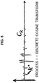
- FIG. 8 is an explanatory chart showing a result C k of the discrete cosine transform in the measuring device according to the embodiment of the present disclosure
- FIG. 9 is an explanatory chart showing the power spectrum of a result P k of the discrete Fourier transform in the measuring device according to the embodiment of the present disclosure.
- FIG. 10 is an explanatory chart showing a result a k of application of an average magnitude difference function in the measuring device according to the embodiment of the present disclosure
- FIG. 11 is a flowchart showing the process of the measuring method executed by the measuring device according to the embodiment of the present disclosure
- FIG. 12 is a flowchart showing the template image automatic acquisition process executed by the measuring device according to an embodiment of the present disclosure
- FIG. 13 is an explanatory illustration showing an exemplary frame included in a video shot outdoor and processed by the measuring device according to the embodiment of the present disclosure.
- FIG. 14 is an explanatory illustration showing a highlighting direction on a spherical body captured in a clipped image.
- the measuring device is typically realized by a computer executing a program.
- the computer is connected to various kinds of output devices and/or input devices and transmits/receives information to/from these devices.
- the program executed by the computer can be distributed/sold by a server to which the computer is communicably connected and besides, can be recorded on a non-transitory information recording medium such as a compact disk read only memory (CD-ROM), a flash memory, and an electrically erasable programmable ROM (EEPROM) and then the information recording medium can be distributed/sold.
- a non-transitory information recording medium such as a compact disk read only memory (CD-ROM), a flash memory, and an electrically erasable programmable ROM (EEPROM) and then the information recording medium can be distributed/sold.
- the program is installed on a non-transitory information recording medium such as a hard disc possessed by a computer, a solid state drive, a flash memory, and an EEPROM.
- the computer realizes the information processing device in this embodiment.
- the central processing unit (CPU) of a computer reads a program into a random access memory (RAM) from an information recording medium and interprets/executes the codes included in the program under the control of the operating system (OS) of the computer.
- OS operating system
- an architecture capable of mapping an information recording medium in a memory space accessible by the CPU explicit loading of a program on an RAM is unnecessary in some cases.
- various kinds of information necessary in the course of executing the program can temporarily be recorded in the RAM.
- the program can be used as a material to generate a wiring chart, a timing chart, or the like of the electronic circuit.
- an electronic circuit fulfilling the specification prescribed in the program is configured by a field programmable gate array (FPGA) or an application specific integrated circuit (ASIC) and the electronic circuit functions as a dedicated device fulfilling the function prescribed in the program to realize the information processing device of this embodiment.
- FPGA field programmable gate array
- ASIC application specific integrated circuit
- the following explanation will be made on the premise that the measuring device is realized by a computer executing the program.
- FIG. 1 is an explanatory diagram showing the general configuration of the measuring device according to an embodiment of the present disclosure. The following explanation will be made with reference to this figure.
- a measuring device 101 comprises a templater 102 , a clipper 103 , a calculator 104 , and an estimator 105 .
- the templater 102 acquires a template image by extracting a circular region in which a spherical body is captured from any of multiple frames included in a video in which the spherical body is captured or a photographic image in which the spherical body is captured under photographing conditions comparable to shooting condition of the video.
- a template image may be extracted based on a user instruction or may be extracted automatically as described later.
- the video is typically one shot with a high speed video camera.
- the video used in this embodiment is assumed to be one shot with a frame rate of 500 FPS or so.
- the frame rate can be changed as appropriate.
- the template image is one obtained by extracting a region including a circular region in which a spherical body is captured from either any frame of a video in which the spherical body is captured or a photographic image captured under photographing conditions comparable to shooting conditions of the video.
- FIG. 2 is an explanatory illustration showing an exemplary frame included in a video processed by the measuring device according to the embodiment of the present disclosure. This figure is one of the frames included in a video in which a baseball pitcher throwing a ball is shot from behind with a high speed video camera approximately 20 m away.
- FIG. 3 is an explanatory illustration showing an exemplary template image acquired by the measuring device according to the embodiment of the present disclosure.
- an image obtained by cutting out a square region in which a spherical body is rendered from any of video frames is used as it is as a template image.
- a template image is extracted from a video to process or a photographic image captured under comparable photographing conditions.
- the template image of this embodiment fulfills the same conditions as other frames in the video with regard to the surrounding environment of shooting such as the brightness of the background, the direction, brightness, and hue of lighting, and the resolution and diaphragm factor of the camera, thereby making highly accurate measurement possible.
- whether the photographing conditions are comparable can be determined by determining whether the above various conditions match. Which condition is to use is determined by experiments or the like.
- the photographic image may be a frame in another video shot under comparable shooting conditions or a template image extracted from another video shot under comparable shooting conditions may be employed as a template image to use in processing a video this time around.
- the clipper 103 acquire a series of clipped images in which a spherical body is rendered so that the spherical body has a center position and a size matched within a given range of errors by extracting from each of multiple frames and enlarging/reducing multiple similar regions each similar to the acquired template image.
- the measuring device 101 obtains multiple clipped images in which the spherical body is rendered in the same size and shares the center by applying masking for removing the background from each frame, template matching for comparing each frame with the template image to extract an area where the spherical body is captured in the frame, and the Hough transform for detecting a circle so as to properly shift and enlarge/reduce the image.
- FIG. 4 is an explanatory illustration showing exemplary clipped images acquired by the measuring device according to the embodiment of the present disclosure. As shown in this figure, the clipped images are expressed in a square of the same size and the spherical body is rendered at the same position and in the same size in the square.
- the calculator 104 calculates similarities/dissimilarities between multiple clipped images and acquires a matrix in which the calculated similarities/dissimilarities are arranged in the shooting order of the frames from which the multiple clipped images are extracted.
- FIG. 5 is an explanatory illustration showing a matrix presenting the similarities/dissimilarities acquired by the measuring device according to the embodiment of the present disclosure.
- the elements of the matrix of similarities/dissimilarities are expressed by black-and-white shading.
- Each element of the matrix of similarities/dissimilarities presents a similarity/dissimilarity between a clipped image having that row number and a clipped image having that column number.
- the dissimilarity may be used which presents how different the clipped images are, as well as the similarity may be used which presents how similar the clipped images are.
- the dissimilarity for example, the weighted average or weighted sum of differences of pixels can be used.
- the similarity for example, the cosine of the angle between the vectors comprising the pixel values of pixels (the inner product of the directional vectors of vectors in which the pixel values are arranged) can be used.
- the shading of the similarities/dissimilarities appears in a diagonal striped pattern.
- the distance between striped patterns corresponds to the spin period.
- the estimator 105 estimates the spin rate of the spherical body from the distribution of elements in the matrix of calculated similarities/dissimilarities. After the spin rate is estimated, it is possible to estimate the spin axis by applying the similarities between clipped images and techniques regarding perspective projection and rotation in a three-dimensional space. Estimation of the spin axis will be described in detail later.
- the spin rate the number of spins per unit time (the spin rate), the spin period, the direction of the spin axis, and the like.
- the above-described processing of each part is executed by the CPU of a computer, an image processor, a dedicated electronic circuit, or the like. Moreover, various kinds of videos and images to process are saved in a storage device such as a RAM, a hard disc, and a solid state drive.
- FIG. 11 is a flowchart showing the process of the measuring method executed by the measuring device according to the embodiment of the present disclosure. The procedure executed by the measuring device 101 will be described in detail below.
- the measuring device 101 receives a video to process (Step S 201 ).
- the video is one in which a spherical body is captured.
- a high speed video camera in shooting makes it possible to analyze the spin of a spherical body with high accuracy. It is necessary based on the sampling theorem to capture a spherical body with a frame rate two or more times higher than a desired spin rate. According to experiments, preferable results are obtained by shooting with a frame rate 10 times or so higher than a presumed spin rate of a spherical body.
- V src the input video to process that is received in the Step S 201 is denoted by V src .
- the pixel value at a pixel position of u (1 ⁇ u ⁇ W (V)) in the width direction and v (1 ⁇ v ⁇ H (V)) in the height direction in a t-th frame (1 ⁇ t ⁇ N (V)) of a video V is denoted by V (u, v, t).
- the value oft divided by the frame rate corresponds to the actual elapsed time and the value of N (V) divided by the frame rate corresponds to the shooting time of the video V.
- W (V) and H (V) are values presenting the width and the height of each frame of the video V in pixels.
- N N ( V src )
- W W ( V src )
- H H ( V src ).
- the measuring device 101 generates an average image I mean and a mask video V mask from the input video V src (Step S 202 ).
- diff (p, q) is an operation to obtain the difference between pixel values p and q.
- p and q are pixels of a gray scale image
- the absolute value of the difference between pixel values may be calculated.
- p and q are pixels of a color image
- the square sum of the differences of elements or the square root thereof may be calculated.
- V src a gray scale video in which the pixel values are 0 to 255.
- BK thresh is a threshold and in the gray scale video of the above specification, for example, a numeric value of 12 to 15 or so is applicable. However, the value can be changed as appropriate.
- noise removal processing it may be possible to apply various kinds of noise removal processing to the mask video V mask and treat the processing result as the mask video V mask .
- an opening process including two times of erosion and two times of dilation per pixel is applied to the mask video V mask .
- the templater 102 of the measuring device 101 obtains a template image I temp based on a user instruction or automatically with reference to this information (Step S 203 ).
- the template image I temp is an image of 2 ⁇ R+1 in width and height obtained by extracting a square region in which the spherical body is rendered from any frame of the input video.
- R is the radius of the spherical body rendered in a frame that is expressed in the number of pixels.
- the pixels in the original frame may be maintained as they are or a transparent color or a predetermined color different from a color assumed for the spherical body may be placed.
- the template image I temp may be acquired from the input video V src based on an instruction from the processing user. However, the template image I temp can be extracted automatically by the method disclosed in the embodiment described later.
- the measuring device 101 After a template image as shown in FIG. 3 is obtained, the measuring device 101 generates a matched video V tm with reference to the input video V src , the mask video V mask , and the template image I temp (Step S 204 ).
- the value of K (u, v, t) may be obtained by multiplying the result of application of the above summation by a proper positive constant or may be the sum of absolute values instead of the square sum.
- the value of V tm (u, v, t) may be obtained by multiplying the result of application of the above exponential function by a proper constant or may be obtained by using some other attenuation function.
- the measuring device 101 extracts useful frames, in other words frames in which the spherical body is captured (Step S 205 ). This is based on the assumption that the spherical body may enter the screen from outside the screen or leave the screen from inside the screen.
- the measuring device 101 sets a proper threshold TM thresh and calculates the maximum value of the pixel values in each frame V tm (u, v, t): max 1 ⁇ u ⁇ W max 1 ⁇ v ⁇ H V tm ( u,v,t ).
- the measuring device 101 searches successions of frames satisfying, with all frame numbers S+1, S ⁇ 2, . . . , and S+N′,
- S+1 is the frame number of a first frame in which the spherical body is captured and N′ is the length of time for which the spherical body is captured in the frames that is expressed in the number of frames.
- the measuring device 101 detects circular shapes by using the Hough transform.
- the measuring device 101 extracts boundary pixels forming a boundary between the pixel values 0 and non-0 in each frame of the mask video V mask and detects a circle fitting most to the boundary pixels by the Hough transform (Step S 206 ).
- the approximate estimated position of the center of a circle detected by comparing with the template image I temp is (x tm (t), y tm (t)); therefore, there is no need of applying the Hough transform to the entire frame of each one of the mask video V mask .
- the calculation time can significantly be reduced.
- the Hough transform may be applied under the condition that assuming that the center position and the radius of a circle detected by the Hough transform in a frame having a frame number t are (x (t), y (t)) and r (t), respectively, these values fall under the following ranges: 0.5 ⁇ R ⁇ r ( t ) ⁇ R; x tm ( t ) ⁇ 0.5 ⁇ R ⁇ x ( t ) ⁇ x tm ( t )+0.5 ⁇ R; y tm ( t ) ⁇ 0.5 ⁇ R ⁇ y ( t ) ⁇ y tm ( t )+0.5 ⁇ R.
- the search range can be extended as appropriate depending on the situation such as the upper limit of r (t) being 1.5 ⁇ R or 2 ⁇ R.
- the upper limit of r (t) may be kept R.
- the clipper 103 of the measuring device 101 clips circular regions having the center position (x (t), y (t)) and the radius r (t) from the frames having the frame numbers S+1, S+2, . . . , and S+N′ of the input video V src and enlarges/reduces the circular regions to a circle of 2 ⁇ R+1 in diameter so as to generate a clipped video V clip comprising square frames of 2 ⁇ R+1 in width and height (Step S 207 ).
- the two factors of enlargement/reduction make a difference in whether to include one surrounding dot, and either one is selected on an arbitrary basis.
- V clip ( u,v,t ) V src (( u ⁇ R ⁇ 1)/ E ( t )+ x ( t ),( v ⁇ R ⁇ 1)/ E ( t )+ y ( t ), t+S ).
- the pixels of the circular background may be assumed to have a pixel value of 0 or the pixel values of the original image may be used as they are as in the above expression.
- various kinds of smoothing processes may be applied. For example, the Gaussian smoothing having a kernel with the standard deviation of two pixels or so is applicable.
- the clipped images as shown in FIG. 4 are obtained.
- the calculator 104 calculates a matrix D presenting the similarities/dissimilarities between frames as follows (Step S 208 ).
- suffixes i and j present an element in a row i and a column j in the matrix.
- G ⁇ (u ⁇ R ⁇ 1, v ⁇ R ⁇ 1) is a weight based on the two-dimensional Gaussian distribution symmetric about the center of each frame of the clipped video.
- G ⁇ ( u ⁇ R ⁇ 1, v ⁇ R ⁇ 1) exp( ⁇ [( u ⁇ R ⁇ 1) 2 +( v ⁇ R ⁇ 1) 2 ]/[2 ⁇ 2 ])
- the spherical body is captured more clearly and accurately near the center than near the edge.
- the weight near the center is augmented.
- a contact such as (2 ⁇ R+1)/6 can be used.
- the values of the elements of the matrix D are expressed by shading and the shading appears in a diagonally striped pattern.
- the similarity/dissimilarity is not restricted to the above calculation formulae and various methods such as the simple squares sum of differences or sum of absolute values of differences can be used.
- the estimator 105 of the measuring device 101 estimates factors of the spin of the spherical body from the distribution of the elements of the matrix (Step S 209 ). First, the method of obtaining the spin period is described below.
- a dissimilarity graph v k corresponding to the average of dissimilarities between frames of which the difference in shooting order is k is obtained by adding the elements in parallel to a diagonal axis of the matrix D.
- FIG. 6 is an explanatory chart showing a dissimilarity graph v k acquired by the measuring device according to the embodiment of the present disclosure.
- v k presents the average element change when the matrix D is seen in the direction of a diagonal axis and it can be seen that low dissimilarity values appear nearly at constant intervals.
- This interval corresponds to the number of frames required for the spherical body to rotate one time.
- the number of frames required for the spherical body to rotate one time is denoted by the cycle T of v k .
- the first method uses the discrete cosine transform.
- FIG. 7 is an explanatory chart showing a dissimilarity graph w k (a dissimilarity graph v k with a Hanning window) acquired by the measuring device according to the embodiment of the present disclosure.
- FIG. 8 is an explanatory chart showing a result C k of the discrete cosine transform in the measuring device according to the embodiment of the present disclosure.
- the second method uses the discrete Fourier transform.
- FIG. 9 is an explanatory chart showing the power spectrum of a result P k of the discrete Fourier transform in the measuring device according to the embodiment of the present disclosure.
- a result of the discrete Fourier transform a sequence of complex numbers P k is obtained. Periodic peaks appear in the power spectrum of the sequence of numbers P k .
- the third method uses an average magnitude difference function.
- the average magnitude difference function a k presents the difference between v i and v i+k that is shifted from v i by k.
- FIG. 10 is an explanatory chart showing a result a k of application of an average magnitude difference function in the measuring device according to the embodiment of the present disclosure.
- the distance between striped patterns (the cycle of change in the average value of similarities/dissimilarities between clipped images equal in the difference of shooting order) T is estimated by multiple methods. Then, if the same value T is obtained by all methods, this means that the measurement result of the spin period is highly accurate.
- the cycles obtained by multiple methods may be different.
- the value obtained by a method may be double the value obtained by another method or may be shifted by 0.5 to 1 from the value obtained by another method.
- which one is employed as the estimated value may be determined by the rule of majority or the user may determine which one is correct.
- T 1 argmin 0 + T / 2 ⁇ k ⁇ ( 1 + T / 2 ) ⁇ v k ;
- T 2 argmin 1 + T / 2 ⁇ k ⁇ ( 1 + T / 2 ) ⁇ v k ;
- T 3 argmin 2 + T / 2 ⁇ k ⁇ ( 3 + T / 2 ) ⁇ v k ; ... ⁇ ;
- T L argmin L - 1 + T / 2 ⁇ k ⁇ ( L + T / 2 ) ⁇ v k in which L is the maximum value satisfying L+T/2 ⁇ N′.
- the obtained cycle T* corresponds to the number of frames necessary for the spherical body to rotate one time.
- the estimated value of the spin period of the spherical body is obtained by dividing T* by the frame rate.
- the number of spins (spin rate) of the spherical body is the inverse of the spin period of the spherical body.
- the spin axis of the spherical body can be estimated.
- a set A of unit vectors a 1 , a 2 , . . . , and a z presenting candidate axis directions of the spin axis is prepared. It is desirable that the unit vectors of the candidates are equally spaced.
- the unit vectors may be obtained from the vertexes of a regular polyhedron or a semiregular polyhedron or by generating random numbers.
- ⁇ (a, k ⁇ 0 ) is a rotation matrix presenting the rotation about a rotation axis in the direction a by an angle k ⁇ 0 .
- the transform between a hemisphere face and a plane is assumed to be parallel projection.
- the measuring device 101 After the spin factors such as the spin period, the number of spins (spin rate), and the direction of the spin axis are obtained, the measuring device 101 outputs the estimated values of the spin factors (Step S 210 ) and ends this procedure.
- FIG. 12 is a flowchart showing the template image automatic acquisition process executed by the measuring device according to an embodiment of the present disclosure.
- Step S 202 a proper frame (a frame number B) is selected from the mask video V mask (Step S 401 ), and the Hough transform for detecting a circle is applied to the boundary pixels between pixel values 0 and 1 within the frame to detect a circle fitting most (Step S 402 ).
- the Hough transform is applied to the entire frame.
- the diameter of a circle used in detection may be 0.5 to 2 times or so larger than the diameter within a typical frame when the spherical body is captured with the camera. This range can be changed as appropriate.
- application of the Hough transform may be preceded by narrowing down. In other words, it may be possible to select all polygons of which the sides are on the boundary between the pixel values 0 and 1 or polygons nearly equal in width and height (for example, 0.8 to 1.25 times), apply the Hough transform to the polygons, and select a circle fitting most as the detection result.
- a circle detection method or a nearly square shape detection method other than the Hough transform may be used. Particularly, there are various high speed algorithms for the method of approximating a captured spherical body to a nearly square shape for detection, and thus it is possible to obtain areas where a spherical body is captured easily and at a high speed.
- a template image I temp is extracted based on those areas (Step S 203 ).
- Step S 403 it is determined whether a frame having a frame number B is included therein and N′ is sufficiently long. Whether N′ is sufficiently long can be determined by, for example, determining whether the ratio of N′ to N is equal to or higher than a threshold (for example, 1 ⁇ 3, 1 ⁇ 4, or the like).
- this determination may be made by measuring an average moving speed of a spherical body, examining by preliminary measurement or the like the length of time for which the spherical body appears in the view of a high speed video camera when the spherical body travels along an average trajectory at that moving speed, and determining whether the ratio of N′ to the number of frames over the length of time of appearance is equal to or higher than a threshold (for example, 1 ⁇ 2, 1 ⁇ 3, or the like).
- a threshold for example, 1 ⁇ 2, 1 ⁇ 3, or the like.
- Step S 403 If N′ is short or the frame number B is not included (Step S 403 ; No), the frame number B selected for extracting a template is improper. In such a case, a frame number is reselected and a temperate image is re-extracted. If the frame number B is proper (Step S 403 ; Yes), the processing proceeds to the Step S 206 and subsequent steps.
- the simplest way of selecting a frame number is to randomly select any frame number. Additionally, it may be possible to set a regular order of frame numbers to select first as below. For example, assuming that the total number of frames is N, a frame number may be reselected in the order of:
- a photographic image may be used instead of a frame having a frame number B.
- multiple frames are randomly selected from the input video V src .
- the Hough transform is applied to each of the selected frames as described above to detect the center and the radius of a circle.
- Template candidates are created by extracting a circular region from frames in which a circle is detected based on the detected center and radius of the circle.
- the template candidates are presented to the user and one in which the spherical body is clearly captured among the template candidates is selected by the user as a template image I temp .
- the above method is applicable to the automatic extraction.
- image parameters such as contrast, clarity, and the radius of a circular region are calculated for each of the template candidates.
- the template candidates are classified into clusters of several candidates (for example, three to five or so) based on the calculated image parameter values.
- One or multiple image parameters may be used for classification into clusters.
- a known technique such as k-means and x-means can be used for classification into clusters.
- a template candidate having best image parameters is selected as a template image I temp from a cluster into which the highest number of template candidates are classified. This is because presumably the images classified into a cluster having a low number of elements are likely to be subjected to noise or false detection.
- the following method can be used. First, averages of the image parameters of all candidates are obtained. Then, divergences presenting how far the image parameters of a candidate are away from the averages are calculated and the candidates are sorted in the ascending order of divergence.
- the candidate ranked in the middle of the sorted order is selected as a template image I temp . It may be possible to select as a template image I temp the candidate ranked not in the middle but 1/ ⁇ down the order from the top in which ⁇ is a constant of 2 to 5 or so. This method is a method of selecting a moderately good candidate that is not far away from the average.
- the candidates may be presented in the ascending order of divergence used in the above.
- a candidate having a large divergence is likely to be subjected to noise or false detection and thus presented down the order, whereby the user can more easily select a template image.
- this embodiment makes it possible to acquire a template image automatically or semiautomatically.
- FIG. 13 is an explanatory illustration showing an exemplary frame included in a video shot outdoor and processed by the measuring device according to the embodiments of the present disclosure.
- the right arm of a pitcher is captured from the bottom left corner to the center of the image and a ball is captured in the top center of the image.
- a crescent moon-shaped highlighted part appears in the upper part of the captured ball.
- the highlighted part occurs when light emitted from lighting including the sun is reflected with a high intensity kept, reaches the camera as it is, and saturates the imaging elements.
- FIG. 14 is an explanatory illustration showing a highlighting direction on a spherical body captured in a clipped image. The following explanation will be made with reference to this figure.
- the part enclosed by an ellipse in the upper part of the ball captured in the clipped image is the center region of the highlighted part.
- the highlighting direction d is the direction from the center of the ball to the center region of the highlighted part.
- the highlighting direction d may be specified explicitly by the user conducting the measurement or may be detected automatically. Various known techniques can be used for automatically detecting the highlighting direction. In this embodiment, it can be assumed that:
- the luminance is expressed in 256 levels from 0 to 255.
- centroid position is the center of the highlighted position.
- pixels having an average luminance H (u, v) equal to or higher than a threshold adjoin and spread over a given or larger area (for example, 20% or more of the captured ball area) around the obtained centroid position. This spread presents the size of the highlighted part.
- the highlighting direction d is determined to be the direction from the center of the clipped image to the obtained centroid position. If the area of the highlighted part is small, the following highlighted part elimination procedure does not need to be executed.
- the two-dimensional Gaussian distribution G ⁇ (u ⁇ R ⁇ 1, v ⁇ R ⁇ 1) is used as a weight in the above explanation.
- the following weight may be used instead of G ⁇ (u ⁇ R ⁇ 1, v ⁇ R ⁇ 1).
- condition “x 2 +y 2 >R 2 ” means that information captured outside the ball in a clipped image may be ignored in calculating the matrix of similarity/dissimilarity D i,j .
- this condition can be used even if the highlighted part has a sufficiently small area or absent.
- condition “(x, y) ⁇ d>0” presents that the inner product of a vector (x, y) and a vector d is positive, in other words the angle between a vector (x, y) and a vector d is smaller than 90 degrees. Therefore, this condition means that that ball is divided at a boundary perpendicular to the highlighting direction d into two, a half in which the highlighted part is present and a half in which the highlighted part is absent and the half in which the highlighted part is present may be ignored in calculating the matrix of similarities/dissimilarities D i,j .
- the measuring device in this embodiment comprises:
- a templater that acquires a template image by extracting a circular region in which a spherical body is captured from any of multiple frames included in a video in which the spherical body is captured or a photographic image in which the spherical body is captured under photographing conditions comparable to shooting conditions of the video;
- a clipper that acquires multiple clipped images in which the spherical body is rendered so that the spherical body has a center position and a size matched within a given range of errors by extracting from each of the multiple frames and enlarges/reduces multiple similar regions each similar to the acquired template image;
- a calculator that calculates similarities/dissimilarities between the multiple clipped images and acquires a matrix in which the calculated similarities/dissimilarities are arranged in the shooting order of the frames from which the multiple clipped images are extracted;
- an estimator that estimates a spin of the spherical body from a distribution of elements in the matrix of calculated similarities/dissimilarities.
- the estimator may obtain an average value of the similarities/dissimilarities between clipped images equal in the difference of shooting order from the distribution of elements in the matrix of similarities/dissimilarities, estimate a change cycle of the average value with respect to the difference of shooting order by multiple different methods, and if the cycles estimated by the multiple methods match, estimate that the matching cycle is a spin period of the spherical.
- the multiple methods may include a method based on the discrete cosine transform, a method based on the discrete Fourier transform, and a method based on an average magnitude difference function.
- the templater may obtain a difference video between the video and an average image of the multiple frames, detect a circular region rendered in the difference video, identifies a circular region in which a size and a position of the detected circular region continuously changes with time, and extract the template image from the identified circular region.
- the templater and the clipper may extract the circular region and the multiple similar regions by the Hough transform.
- the estimator may estimate a spin axis about which the spherical body rotates by minimizing a difference between multiple assumptive images obtained by assuming that the spherical body rotates about a candidate spin axis and the multiple clipped images.
- a template step in which a measuring device acquires a template image by extracting a circular region in which a spherical body is captured from any of multiple frames included in a video in which the spherical body is captured or a photographic image in which the spherical body is captured under photographing conditions comparable to shooting conditions of the video;
- a clipping step in which the measuring device acquires multiple clipped images in which the spherical body is rendered so that the spherical body has a center position and a size matched within a given range of errors by extracting from each of the multiple frames and enlarging/reducing multiple similar regions each similar to the acquired template image;
- a calculation step in which the measuring device calculates similarities/dissimilarities between the multiple clipped images and acquires a matrix in which the calculated similarities/dissimilarities are arranged in the shooting order of the frames from which the multiple clipped images are extracted;
- an estimation step in which the measuring device estimates a spin of the spherical body from a distribution of elements in the matrix of calculated similarities/dissimilarities.
- a templater that acquires a template image by extracting a circular region in which a spherical body is captured from any of multiple frames included in a video in which the spherical body is captured or a photographic image in which the spherical body is captured under photographing conditions comparable to shooting conditions of the video;
- a clipper that acquires multiple clipped images in which the spherical body is rendered so that the spherical body has a center position and a size matched within a given range of errors by extracting from each of the multiple frames and enlarges/reduces multiple similar regions each similar to the acquired template image;
- a calculator that calculates similarities/dissimilarities between the multiple clipped images and acquires a matrix in which the calculated similarities/dissimilarities are arranged in the shooting order of the frames from which the multiple clipped images are extracted;
- an estimator that estimates a spin of the spherical body from a distribution of elements in the matrix of calculated similarities/dissimilarities.
- the present disclosure can provide a measuring device and a measuring method for measuring the spin of a spherical body and a program for realizing the measuring device and the measuring method by a computer.
Abstract
Description
N=N(V src),W=W(V src),H=H(V src).
I mean(u,v)=Σt=1 N V src(u,v,t)/N.
V mask(u,v,t)=0, if diff(V src(u,v,t),I mean(u,v))<BK thresh;
V mask(u,v,t)=1, otherwise.
K(u,v,t)=Σi=−R R[V src(u+i,v+j,t)−I temp(i+R+1,j+R+1)]2;
V tm(u,v,t)=0, if V mask(u,v,t)=0;
V tm(u,v,t)=exp(−[K(u,v,t)]2), if V mask#0.
Here, the background of the template image Itemp can be ignored. In other words,
K(u,v,t)=Σi=−R RΣj=−R R fn·(i,j,t)2;
fn(i,j,t)=V src(u+i,v+j,t)−I temp(i+R+1,j+R+1), if (i+R+ 1)2+(j+R+1)2≤(R+1)2;
fn(i,j,t)=0,otherwise.
This corresponds to use of a circle as the shape of a template image.
max1≤u≤W max1≤v≤H V tm(u,v,t).
for the one of which N′ is the highest. As a result, when the spherical body once leaves the screen and reenters the screen, a longer succession of frames are selected.
(x tm(t),y tm(t))=argmax(u,v)|1≤u≤W,1≤v≤H V tm(u,v,t).
In other words, it may be possible to search for a pixel having the maximum pixel value in a frame and acquire the position of the pixel.
0.5×R≤r(t)≤R;
x tm(t)−0.5×R≤x(t)≤x tm(t)+0.5×R;
y tm(t)−0.5×R≤y(t)≤y tm(t)+0.5×R.
Here, when the spherical body is shot in the direction of gradually approaching the camera, for example a ball is shot from behind the catcher in the direction of the pitcher, the search range can be extended as appropriate depending on the situation such as the upper limit of r (t) being 1.5×R or 2×R.
E(t)=R/r(t)
or
E(t)=(2×R+1)/(2×R(t)),
and then coordinate-transformed so that the origin moves to (R+1, R+1) to obtain a frame having a frame number t of the clipped video Vclip. The two factors of enlargement/reduction make a difference in whether to include one surrounding dot, and either one is selected on an arbitrary basis. The simplest correspondence in pixel value between the clipped video Vclip and the input video Vsrc is as follows:
V clip(u,v,t)=V src((u−R−1)/E(t)+x(t),(v−R−1)/E(t)+y(t),t+S).
In the clipped video Vclip (u, v, t), 1≤u≤2×R+1, 1≤v≤2×R+1, and 1≤t≤N′ are the useful ranges. In other words,
H(V clip)=W(V clip)=2×R+1;
N(V clip)=N′.
D i,j=Σu=1 2×R+1Σv=1 2×R+1 G σ(u−R−1,v−R−1)×[V clip(u,v,i)−V clip(u,v,j)]2
Gσ(u−R−1,v−R−1)=exp(−[(u−R−1)2+(v−R−1)2]/[2×σ2])
In other words, the spherical body is captured more clearly and accurately near the center than near the edge. Then, the weight near the center is augmented. As the standard deviation 6 presenting the spread of the Gaussian distribution, for example, a contact such as (2×R+1)/6 can be used.
v k=Σi=1 N′/3 D i,j+k
C k=Σn=1 M w n×cos [π×k×(2×n+1)/(2×M)];
w k =C 1/2+Σn=2 M C n×cos [(π×n×(2×k+1)/(2×M)].
T=2×M/k*−0.5.
P f=(1/M)×Σn=1 M w n×exp(−i×2×π×k×n/M).
T=M/k*.
a k=1/[M−k]×Σi=1 M−k |v i −v i+k|.
The average magnitude difference function ak presents the difference between vi and vi+k that is shifted from vi by k.
T=k*.
in which L is the maximum value satisfying L+T/2≤N′.
T*=(T L −T 1)/(L−1).
Here, the obtained cycle T* corresponds to the number of frames necessary for the spherical body to rotate one time. Thus, the estimated value of the spin period of the spherical body is obtained by dividing T* by the frame rate. Moreover, the number of spins (spin rate) of the spherical body is the inverse of the spin period of the spherical body.
J mean(u,v)=V clip(u,v,t)/N′;
V ball(u,v,t)=V clip(u,v,t)−J mean(u,v).
ω0=2×π/T*
in one frame.
f(u,v)=((u−R−1)/R,(v−R−1)/R,[1−((u−R−1)/R)2−((v−R−1)/R)2]1/2);
f −1(x,y,z)=(x×R+R+1,y×R+R+1);
(u′,v′)=f −1(ρ(a,k×ω 0)f(u,v)).
in which ρ (a, k×ω0) is a rotation matrix presenting the rotation about a rotation axis in the direction a by an angle k×ω0. Moreover, the transform between a hemisphere face and a plane is assumed to be parallel projection.
(u″,v″)=f −1(ρ(a,−k×ω 0)f(u,v)).
E(a)=Σt=1 T*Σu=1 2×R+1Σv=1 2×R+1 G σ(u,v)[V ball(u,v,t)−V ball(u′,v′,t+k)]2+Σt=1 T*Σu=1 2×R+1Σv=1 2×R+1 G σ(u,v)[V ball(u″,v″,t)−V ball(u′,v′,t+k)]2.
Alternatively, the evaluation function E (a) may be set as follows:
E(a)={Σt=1 T*Σu=1 2×R+1Σv=1 2×R+1 G σ(u,v)Gσ(u′,v′)[V ball(u,v,t)−V ball(u′,v′,t+k)]2}/{Σt=1 T*Σu=1 2×R+1Σv=1 2×R+1 G σ(u,v)G σ(u′,v′)}.
a*=argmina∈A E(a).
H(u,v)=Σt=1 N(V) V clip(u,v,t)/N(V).
M(x,y)=0, if x 2 +y 2 >R 2 or (x,y)□d>0;
M(x,y)=G σ(x,y), otherwise.
- 101 Measuring device
- 102 Templater
- 103 Clipper
- 104 Calculator
- 105 Estimator
Claims (11)
Applications Claiming Priority (3)
| Application Number | Priority Date | Filing Date | Title |
|---|---|---|---|
| JP2015054616 | 2015-03-18 | ||
| JP2015-054616 | 2015-03-18 | ||
| PCT/JP2016/058545 WO2016148247A1 (en) | 2015-03-18 | 2016-03-17 | Device for measuring rotation of spherical body, measurement method, and program |
Publications (2)
| Publication Number | Publication Date |
|---|---|
| US20180174308A1 US20180174308A1 (en) | 2018-06-21 |
| US10586339B2 true US10586339B2 (en) | 2020-03-10 |
Family
ID=56918943
Family Applications (1)
| Application Number | Title | Priority Date | Filing Date |
|---|---|---|---|
| US15/558,393 Active 2036-08-27 US10586339B2 (en) | 2015-03-18 | 2016-03-17 | Device for measuring rotation of spherical body, measurement method, and program |
Country Status (4)
| Country | Link |
|---|---|
| US (1) | US10586339B2 (en) |
| JP (1) | JP6566449B2 (en) |
| TW (1) | TWI687689B (en) |
| WO (1) | WO2016148247A1 (en) |
Cited By (1)
| Publication number | Priority date | Publication date | Assignee | Title |
|---|---|---|---|---|
| US11396352B2 (en) | 2020-04-13 | 2022-07-26 | Eric R. Sirkin | Methods and apparatus for measuring and monitoring an anchoring operation |
Families Citing this family (8)
| Publication number | Priority date | Publication date | Assignee | Title |
|---|---|---|---|---|
| CN105825228B (en) * | 2016-03-14 | 2019-04-30 | 百度在线网络技术(北京)有限公司 | Image-recognizing method and device |
| KR20180002408A (en) * | 2016-06-29 | 2018-01-08 | 주식회사 크리에이츠 | Method, system and non-transitory computer-readable recording medium for measuring ball spin |
| CN111345772B (en) * | 2018-12-20 | 2022-06-10 | 重庆金山医疗技术研究院有限公司 | Method for adjusting image acquisition frame rate and capsule endoscope system |
| JP7107440B2 (en) * | 2019-06-24 | 2022-07-27 | 日本電信電話株式会社 | LEARNING DATA GENERATION DEVICE, LEARNING DATA GENERATION METHOD, AND PROGRAM |
| CN111739098A (en) * | 2020-06-30 | 2020-10-02 | 上海商汤智能科技有限公司 | Speed measuring method and device, electronic equipment and storage medium |
| US20240112346A1 (en) * | 2021-01-28 | 2024-04-04 | Nippon Telegraph And Telephone Corporation | Rotation state estimation apparatus, method thereof, and program |
| TWI764768B (en) * | 2021-06-25 | 2022-05-11 | 國立高雄科技大學 | Method and system for predicting the track of a table tennis |
| CN116277037B (en) * | 2023-05-19 | 2023-07-25 | 泓浒(苏州)半导体科技有限公司 | Wafer handling mechanical arm control system and method |
Citations (10)
| Publication number | Priority date | Publication date | Assignee | Title |
|---|---|---|---|---|
| JPH0968539A (en) | 1995-06-19 | 1997-03-11 | Sumitomo Rubber Ind Ltd | Rotating speed measuring device for flying sphere |
| JP2002333312A (en) | 2001-05-09 | 2002-11-22 | Sumitomo Rubber Ind Ltd | Measurement method for three dimensional posture of sphere and measuring method for revolution rate and direction of revolution axis of sphere using the method |
| JP2005291824A (en) | 2004-03-31 | 2005-10-20 | Yokohama National Univ | Flying behavior measuring apparatus of flying object, and flying behavior measuring method of flying object |
| FR2880952A1 (en) | 2005-01-19 | 2006-07-21 | Renault Sas | Valve`s rotation movement characterizing method for internal combustion engine of motor vehicle, involves establishing variation curve of angular position of valve based on angular position of camshaft controlling valve |
| JP2008522707A (en) | 2004-12-06 | 2008-07-03 | ブライアン フランシス ムーニー | Spin measurement method and apparatus |
| JP2009042196A (en) | 2007-08-13 | 2009-02-26 | Yokohama Rubber Co Ltd:The | Rotation speed detection system and rotation speed detection device |
| JP2012058066A (en) | 2010-09-08 | 2012-03-22 | Shinshu Univ | Device and method for detecting rotation of sphere |
| US20130135466A1 (en) * | 2011-11-25 | 2013-05-30 | Electronics And Telecommunications Research Institute | Method and apparatus for measuring rotation characteristics of rotating body |
| WO2013174707A1 (en) | 2012-05-25 | 2013-11-28 | Marposs Societa' Per Azioni | Method for estimating the rotational speed of a tool mounted on a rotating spindle of a machine tool and such a machine tool |
| US20140185881A1 (en) | 2012-12-28 | 2014-07-03 | Casio Computer Co., Ltd. | Image analysis apparatus to analyze state of predetermined object in image |
Family Cites Families (1)
| Publication number | Priority date | Publication date | Assignee | Title |
|---|---|---|---|---|
| JP5109221B2 (en) * | 2002-06-27 | 2012-12-26 | 新世代株式会社 | Information processing device equipped with an input system using a stroboscope |
-
2016
- 2016-03-17 US US15/558,393 patent/US10586339B2/en active Active
- 2016-03-17 WO PCT/JP2016/058545 patent/WO2016148247A1/en active Application Filing
- 2016-03-17 JP JP2017506616A patent/JP6566449B2/en active Active
- 2016-03-18 TW TW105108486A patent/TWI687689B/en active
Patent Citations (15)
| Publication number | Priority date | Publication date | Assignee | Title |
|---|---|---|---|---|
| JPH0968539A (en) | 1995-06-19 | 1997-03-11 | Sumitomo Rubber Ind Ltd | Rotating speed measuring device for flying sphere |
| GB2319834A (en) | 1995-06-19 | 1998-06-03 | Sumitomo Rubber Ind | Measurement of rotation speed of a flying object |
| JP2002333312A (en) | 2001-05-09 | 2002-11-22 | Sumitomo Rubber Ind Ltd | Measurement method for three dimensional posture of sphere and measuring method for revolution rate and direction of revolution axis of sphere using the method |
| US20030031359A1 (en) | 2001-05-09 | 2003-02-13 | Mitsunori Miki | Method and apparatus of measuring three-dimensional posture of sphere and method of measuring rotational amount of sphere and direction of rotational axis thereof |
| JP2005291824A (en) | 2004-03-31 | 2005-10-20 | Yokohama National Univ | Flying behavior measuring apparatus of flying object, and flying behavior measuring method of flying object |
| US20050233816A1 (en) | 2004-03-31 | 2005-10-20 | Koichi Nishino | Apparatus and method of measuring the flying behavior of a flying body |
| US20090237641A1 (en) | 2004-12-06 | 2009-09-24 | Brian Francis Mooney | Spin measurement method and apparatus |
| JP2008522707A (en) | 2004-12-06 | 2008-07-03 | ブライアン フランシス ムーニー | Spin measurement method and apparatus |
| FR2880952A1 (en) | 2005-01-19 | 2006-07-21 | Renault Sas | Valve`s rotation movement characterizing method for internal combustion engine of motor vehicle, involves establishing variation curve of angular position of valve based on angular position of camshaft controlling valve |
| JP2009042196A (en) | 2007-08-13 | 2009-02-26 | Yokohama Rubber Co Ltd:The | Rotation speed detection system and rotation speed detection device |
| JP2012058066A (en) | 2010-09-08 | 2012-03-22 | Shinshu Univ | Device and method for detecting rotation of sphere |
| US20130135466A1 (en) * | 2011-11-25 | 2013-05-30 | Electronics And Telecommunications Research Institute | Method and apparatus for measuring rotation characteristics of rotating body |
| WO2013174707A1 (en) | 2012-05-25 | 2013-11-28 | Marposs Societa' Per Azioni | Method for estimating the rotational speed of a tool mounted on a rotating spindle of a machine tool and such a machine tool |
| US20140185881A1 (en) | 2012-12-28 | 2014-07-03 | Casio Computer Co., Ltd. | Image analysis apparatus to analyze state of predetermined object in image |
| JP2014130106A (en) | 2012-12-28 | 2014-07-10 | Casio Comput Co Ltd | Image analysis device, information notification device, image analysis method, information notification method and program |
Non-Patent Citations (3)
| Title |
|---|
| Ijiri et al., "Automatic Spin Measurements for Pitched Baseballs via Consumer-Grade High-Speed Cameras (Supplementary Material)", Signal, Image and Video Processing, Manuscript Draft, Manuscript No. SIVP-D-16-00278R2, 1 pages. |
| Ijiri et al., "Automatic Spin Measurements for Pitched Baseballs via Consumer-Grade High-Speed Cameras", Signal, Image and Video Processing, Manuscript Draft, Manuscript No. SIVP-D-16-00278R2,12 pages. |
| International Search Report dated May 31, 2016 from corresponding International PCT Application No. PCT/JP2016/058545, 2 pages. |
Cited By (1)
| Publication number | Priority date | Publication date | Assignee | Title |
|---|---|---|---|---|
| US11396352B2 (en) | 2020-04-13 | 2022-07-26 | Eric R. Sirkin | Methods and apparatus for measuring and monitoring an anchoring operation |
Also Published As
| Publication number | Publication date |
|---|---|
| US20180174308A1 (en) | 2018-06-21 |
| JP6566449B2 (en) | 2019-08-28 |
| JPWO2016148247A1 (en) | 2018-01-11 |
| TW201702600A (en) | 2017-01-16 |
| TWI687689B (en) | 2020-03-11 |
| WO2016148247A1 (en) | 2016-09-22 |
Similar Documents
| Publication | Publication Date | Title |
|---|---|---|
| US10586339B2 (en) | Device for measuring rotation of spherical body, measurement method, and program | |
| JP6863408B2 (en) | Information processing equipment, information processing methods and programs | |
| US9881204B2 (en) | Method for determining authenticity of a three-dimensional object | |
| US8755573B2 (en) | Time-of-flight sensor-assisted iris capture system and method | |
| US9619708B2 (en) | Method of detecting a main subject in an image | |
| US8203602B2 (en) | Depth-aware blur kernel estimation method for iris deblurring | |
| US20210227132A1 (en) | Method for tracking target in panoramic video, and panoramic camera | |
| JP6525635B2 (en) | Image processing apparatus, image processing method and program | |
| US20180039856A1 (en) | Image analyzing apparatus, image analyzing method, and recording medium | |
| US9433345B2 (en) | Cycloduction measurement device, cycloduction measurement method, and cycloduction measurement program | |
| US11074698B2 (en) | Object tracking device and object tracking method | |
| Makinana et al. | Quality parameter assessment on iris images | |
| JP7243372B2 (en) | Object tracking device and object tracking method | |
| US10855918B2 (en) | Image processing device, image processing method, image pickup apparatus, and program storage medium that calculates a matching degree between an estimated target of interest and tracked feature points, then selects a feature point to which tracking is continued according to the matching degree | |
| US9721151B2 (en) | Method and apparatus for detecting interfacing region in depth image | |
| EP3671625B1 (en) | Method, device, and system for enhancing changes in an image captured by a thermal camera | |
| JP7103443B2 (en) | Information processing equipment, information processing methods, and programs | |
| Makinana et al. | Iris image quality assessment based on quality parameters | |
| Schug | Three dimensional edge detection using wavelet and shearlet analysis | |
| Taleb et al. | Stars Detection and Localisation Improvement Based on Image Processing | |
| Langmann et al. | Multiple Camera 2D/3D Tracking | |
| JP2014071664A (en) | Image processor and image processing method |
Legal Events
| Date | Code | Title | Description |
|---|---|---|---|
| FEPP | Fee payment procedure |
Free format text: ENTITY STATUS SET TO UNDISCOUNTED (ORIGINAL EVENT CODE: BIG.); ENTITY STATUS OF PATENT OWNER: LARGE ENTITY |
|
| AS | Assignment |
Owner name: RIKEN, JAPAN Free format text: ASSIGNMENT OF ASSIGNORS INTEREST;ASSIGNORS:IJIRI, TAKASHI;HIMENO, RYUTARO;SIGNING DATES FROM 20171028 TO 20171030;REEL/FRAME:044148/0380 |
|
| STPP | Information on status: patent application and granting procedure in general |
Free format text: DOCKETED NEW CASE - READY FOR EXAMINATION |
|
| STPP | Information on status: patent application and granting procedure in general |
Free format text: NON FINAL ACTION MAILED |
|
| STPP | Information on status: patent application and granting procedure in general |
Free format text: RESPONSE TO NON-FINAL OFFICE ACTION ENTERED AND FORWARDED TO EXAMINER |
|
| STPP | Information on status: patent application and granting procedure in general |
Free format text: NOTICE OF ALLOWANCE MAILED -- APPLICATION RECEIVED IN OFFICE OF PUBLICATIONS |
|
| STPP | Information on status: patent application and granting procedure in general |
Free format text: PUBLICATIONS -- ISSUE FEE PAYMENT VERIFIED |
|
| STCF | Information on status: patent grant |
Free format text: PATENTED CASE |
|
| FEPP | Fee payment procedure |
Free format text: MAINTENANCE FEE REMINDER MAILED (ORIGINAL EVENT CODE: REM.); ENTITY STATUS OF PATENT OWNER: LARGE ENTITY |
|
| FEPP | Fee payment procedure |
Free format text: SURCHARGE FOR LATE PAYMENT, LARGE ENTITY (ORIGINAL EVENT CODE: M1554); ENTITY STATUS OF PATENT OWNER: LARGE ENTITY |
|
| MAFP | Maintenance fee payment |
Free format text: PAYMENT OF MAINTENANCE FEE, 4TH YEAR, LARGE ENTITY (ORIGINAL EVENT CODE: M1551); ENTITY STATUS OF PATENT OWNER: LARGE ENTITY Year of fee payment: 4 |