WO2016148009A1 - Bearing device and machine device - Google Patents
Bearing device and machine device Download PDFInfo
- Publication number
- WO2016148009A1 WO2016148009A1 PCT/JP2016/057560 JP2016057560W WO2016148009A1 WO 2016148009 A1 WO2016148009 A1 WO 2016148009A1 JP 2016057560 W JP2016057560 W JP 2016057560W WO 2016148009 A1 WO2016148009 A1 WO 2016148009A1
- Authority
- WO
- WIPO (PCT)
- Prior art keywords
- bearing
- lubricating oil
- inner ring
- outer ring
- supply unit
- Prior art date
Links
Images

Classifications
-
- F—MECHANICAL ENGINEERING; LIGHTING; HEATING; WEAPONS; BLASTING
- F16—ENGINEERING ELEMENTS AND UNITS; GENERAL MEASURES FOR PRODUCING AND MAINTAINING EFFECTIVE FUNCTIONING OF MACHINES OR INSTALLATIONS; THERMAL INSULATION IN GENERAL
- F16C—SHAFTS; FLEXIBLE SHAFTS; ELEMENTS OR CRANKSHAFT MECHANISMS; ROTARY BODIES OTHER THAN GEARING ELEMENTS; BEARINGS
- F16C33/00—Parts of bearings; Special methods for making bearings or parts thereof
- F16C33/30—Parts of ball or roller bearings
- F16C33/58—Raceways; Race rings
- F16C33/583—Details of specific parts of races
-
- F—MECHANICAL ENGINEERING; LIGHTING; HEATING; WEAPONS; BLASTING
- F16—ENGINEERING ELEMENTS AND UNITS; GENERAL MEASURES FOR PRODUCING AND MAINTAINING EFFECTIVE FUNCTIONING OF MACHINES OR INSTALLATIONS; THERMAL INSULATION IN GENERAL
- F16C—SHAFTS; FLEXIBLE SHAFTS; ELEMENTS OR CRANKSHAFT MECHANISMS; ROTARY BODIES OTHER THAN GEARING ELEMENTS; BEARINGS
- F16C33/00—Parts of bearings; Special methods for making bearings or parts thereof
- F16C33/30—Parts of ball or roller bearings
- F16C33/66—Special parts or details in view of lubrication
- F16C33/6637—Special parts or details in view of lubrication with liquid lubricant
- F16C33/664—Retaining the liquid in or near the bearing
-
- F—MECHANICAL ENGINEERING; LIGHTING; HEATING; WEAPONS; BLASTING
- F16—ENGINEERING ELEMENTS AND UNITS; GENERAL MEASURES FOR PRODUCING AND MAINTAINING EFFECTIVE FUNCTIONING OF MACHINES OR INSTALLATIONS; THERMAL INSULATION IN GENERAL
- F16C—SHAFTS; FLEXIBLE SHAFTS; ELEMENTS OR CRANKSHAFT MECHANISMS; ROTARY BODIES OTHER THAN GEARING ELEMENTS; BEARINGS
- F16C33/00—Parts of bearings; Special methods for making bearings or parts thereof
- F16C33/30—Parts of ball or roller bearings
- F16C33/66—Special parts or details in view of lubrication
- F16C33/6637—Special parts or details in view of lubrication with liquid lubricant
- F16C33/6659—Details of supply of the liquid to the bearing, e.g. passages or nozzles
- F16C33/6674—Details of supply of the liquid to the bearing, e.g. passages or nozzles related to the amount supplied, e.g. gaps to restrict flow of the liquid
-
- F—MECHANICAL ENGINEERING; LIGHTING; HEATING; WEAPONS; BLASTING
- F16—ENGINEERING ELEMENTS AND UNITS; GENERAL MEASURES FOR PRODUCING AND MAINTAINING EFFECTIVE FUNCTIONING OF MACHINES OR INSTALLATIONS; THERMAL INSULATION IN GENERAL
- F16C—SHAFTS; FLEXIBLE SHAFTS; ELEMENTS OR CRANKSHAFT MECHANISMS; ROTARY BODIES OTHER THAN GEARING ELEMENTS; BEARINGS
- F16C33/00—Parts of bearings; Special methods for making bearings or parts thereof
- F16C33/30—Parts of ball or roller bearings
- F16C33/66—Special parts or details in view of lubrication
- F16C33/6637—Special parts or details in view of lubrication with liquid lubricant
- F16C33/6681—Details of distribution or circulation inside the bearing, e.g. grooves on the cage or passages in the rolling elements
-
- F—MECHANICAL ENGINEERING; LIGHTING; HEATING; WEAPONS; BLASTING
- F16—ENGINEERING ELEMENTS AND UNITS; GENERAL MEASURES FOR PRODUCING AND MAINTAINING EFFECTIVE FUNCTIONING OF MACHINES OR INSTALLATIONS; THERMAL INSULATION IN GENERAL
- F16N—LUBRICATING
- F16N7/00—Arrangements for supplying oil or unspecified lubricant from a stationary reservoir or the equivalent in or on the machine or member to be lubricated
- F16N7/38—Arrangements for supplying oil or unspecified lubricant from a stationary reservoir or the equivalent in or on the machine or member to be lubricated with a separate pump; Central lubrication systems
-
- F—MECHANICAL ENGINEERING; LIGHTING; HEATING; WEAPONS; BLASTING
- F16—ENGINEERING ELEMENTS AND UNITS; GENERAL MEASURES FOR PRODUCING AND MAINTAINING EFFECTIVE FUNCTIONING OF MACHINES OR INSTALLATIONS; THERMAL INSULATION IN GENERAL
- F16C—SHAFTS; FLEXIBLE SHAFTS; ELEMENTS OR CRANKSHAFT MECHANISMS; ROTARY BODIES OTHER THAN GEARING ELEMENTS; BEARINGS
- F16C19/00—Bearings with rolling contact, for exclusively rotary movement
- F16C19/02—Bearings with rolling contact, for exclusively rotary movement with bearing balls essentially of the same size in one or more circular rows
- F16C19/14—Bearings with rolling contact, for exclusively rotary movement with bearing balls essentially of the same size in one or more circular rows for both radial and axial load
- F16C19/16—Bearings with rolling contact, for exclusively rotary movement with bearing balls essentially of the same size in one or more circular rows for both radial and axial load with a single row of balls
- F16C19/163—Bearings with rolling contact, for exclusively rotary movement with bearing balls essentially of the same size in one or more circular rows for both radial and axial load with a single row of balls with angular contact
-
- F—MECHANICAL ENGINEERING; LIGHTING; HEATING; WEAPONS; BLASTING
- F16—ENGINEERING ELEMENTS AND UNITS; GENERAL MEASURES FOR PRODUCING AND MAINTAINING EFFECTIVE FUNCTIONING OF MACHINES OR INSTALLATIONS; THERMAL INSULATION IN GENERAL
- F16C—SHAFTS; FLEXIBLE SHAFTS; ELEMENTS OR CRANKSHAFT MECHANISMS; ROTARY BODIES OTHER THAN GEARING ELEMENTS; BEARINGS
- F16C19/00—Bearings with rolling contact, for exclusively rotary movement
- F16C19/54—Systems consisting of a plurality of bearings with rolling friction
- F16C19/546—Systems with spaced apart rolling bearings including at least one angular contact bearing
- F16C19/547—Systems with spaced apart rolling bearings including at least one angular contact bearing with two angular contact rolling bearings
Definitions
- the present invention relates to a bearing device and a mechanical device, and more particularly to a bearing device and a mechanical device in which a lubricating oil supply unit that supplies lubricating oil to the inside of the bearing is installed adjacent to the bearing.
- Patent Document 1 A rolling bearing device in which an oil supply unit is incorporated in a rolling bearing has been known (see Japanese Patent Application Laid-Open No. 2014-37879 (Patent Document 1)).
- the bearing device disclosed in Patent Document 1 is capable of stably supplying lubricant to a bearing for a long period of time by intermittently operating a pump from a lubricant tank disposed in a spacer adjacent to the bearing. .
- the present invention has been made to solve the above-described problems, and a bearing device that can be stably operated for a long period of time by reliably supplying the supplied lubricating oil to the bearing lubrication.
- a mechanical device to which the bearing device is applied is provided.
- a bearing device includes a bearing and a lubricating oil supply unit connected to the bearing.
- the bearing includes an outer ring having an outer ring rolling surface on the inner peripheral surface, an inner ring disposed on the inner side of the outer ring so that the inner ring rolling surface is opposed to the outer ring rolling surface.
- a plurality of rolling elements that are in contact with the outer ring rolling surface and the inner ring rolling surface and arranged side by side on an annular track.
- the lubricating oil supply unit includes a holding unit that holds the lubricating oil supplied to the inside of the bearing, a supplying unit that supplies the lubricating oil from the holding unit to the inside of the bearing, and a power generation unit that generates electric power.
- the supply unit is operated by the electric power generated in the power generation unit, and the outer peripheral surface of the inner ring includes an inclined part that approaches the outer ring as it goes from the end in the axial direction of the bearing toward the inner ring rolling surface. Supply toward the inclined part of the inner ring.
- a mechanical device includes a rotating shaft, a housing disposed on an outer peripheral side of the rotating shaft, and the bearing device that rotatably supports the rotating shaft with respect to the housing.
- FIG. 2 is a schematic cross-sectional view taken along line II-II in FIG. It is a cross-sectional schematic diagram which shows the nozzle member of the bearing apparatus shown in FIG. It is a cross-sectional schematic diagram of the mechanical apparatus to which the bearing apparatus shown in FIG. 1 is applied. It is a cross-sectional schematic diagram of the mechanical apparatus shown in FIG.
- the bearing device 10 according to the present embodiment is a rolling bearing device, and includes a bearing 11 (see FIG. 2) that is a rolling bearing and a lubricating oil supply unit 20 (see FIG. 2).
- the lubricating oil supply unit 20 is incorporated between an outer ring spacer 33 and an inner ring spacer 34 that are abutted against one end of the bearing 11 in the axial direction.
- a bearing device 10 including a bearing 11 and a lubricating oil supply unit 20 is used by being incorporated, for example, between a rotating shaft and a housing of a mechanical device.
- the bearing device 10 When the bearing device 10 is incorporated in a mechanical device, for example, another spacer may be abutted against the other end of the bearing 11.
- the bearing 11 can be positioned in the axial direction by the outer ring spacer 33, the inner ring spacer 34, and other spacers.
- the bearing 11 includes, for example, an inner ring 14 which is a rotating raceway ring, a fixed outer ring 13, a plurality of rolling elements 15 interposed between the inner ring 14 and the outer ring 13, and a plurality of rolling elements 15.
- a retainer 16 that holds a fixed distance at a predetermined interval
- a seal member that is disposed on the outer peripheral side of the retainer 16.
- the bearing 11 for example, an angular ball bearing, a deep groove ball bearing, or a cylindrical roller bearing can be used.
- the bearing 11 is filled with desired grease in advance.
- the seal member is disposed at the end opposite to the side where the outer ring spacer 33 or the like is disposed.
- an inner ring rolling surface with which the rolling element 15 contacts is formed on the outer circumferential surface.
- the outer peripheral surface includes an inclined portion 14a connected to the inner ring rolling surface.
- the inclined portion 14a is inclined with respect to the axial direction so as to approach the outer ring 13 from the end in the axial direction of the inner ring 14 toward the inner ring rolling surface.
- the inclination angle ⁇ 1 with respect to the axial direction of the inclined portion 14a is, for example, not less than 5 ° and not more than 45 °.
- the lower limit of the inclination angle ⁇ 1 may be 10 °.
- the upper limit of the inclination angle ⁇ 1 may be 40 ° or 35 °.
- a concave portion 14b is formed in the inclined portion 14a.
- the recess 14 b is a circumferential groove extending in the circumferential direction of the bearing 11.
- the depth of the recess 14b is, for example, not less than 0.1 mm and not more than 2 mm.
- the lower limit of the depth of the recess 14b may be 0.2 mm or 0.3 mm.
- the upper limit of the depth of the recess 14b may be 1.8 mm, 1.5 mm, or 1.0 mm.
- the shape of the recessed part 14b in the cross section along the axial direction of the bearing 11 may be semicircular, and may be V-shaped.
- the shape of the recess 14b in the cross section may include a curved line or may include a straight line.
- the inner ring spacer 34 and the outer ring spacer 33 constitute a spacer.
- the inner ring spacer 34 is abutted against one end face of the inner ring 14.
- the outer ring spacer 33 is abutted against one end face of the outer ring 13.
- the lubricating oil supply unit 20 mainly includes a power generation unit 25, a power circuit 26, a control circuit 27, a driving circuit 28, a pump 29, and a lubricating oil tank 30 that are arranged in a circumferential direction in an annular housing.
- the power supply circuit 26 may include a charging unit.
- the lubricating oil tank 30 stores the same type of lubricating oil as the base oil of the grease sealed in the bearing 11.
- the power generation unit 25, the power supply circuit 26, the control circuit 27, the drive circuit 28, the pump 29, and the lubricating oil tank 30 are arranged in the circumferential direction in the housing body 21.
- the power generation unit 25 is connected to the power supply circuit 26.
- the power supply circuit 26 is connected to the control circuit 27.
- the control circuit 27 is connected to the drive circuit 28.
- the drive circuit 28 is a circuit for operating a pump 29 such as a micropump. Connected to the pump 29 connected to the drive circuit 28 are a suction tube 31 connected to the bag body of the lubricating oil tank 30 and a discharge tube 32 for supplying lubricating oil from the pump 29 to the inside of the bearing 11. Has been.
- a nozzle member 37 is connected to the distal end of the discharge tube 32 (the end opposite to the root connected to the pump 29) as shown in FIG.
- a nozzle hole 37 a connected to the discharge tube 32 is formed in the nozzle member 37.
- the nozzle member 37 is connected to the annular housing of the lubricating oil supply unit 20.
- the annular housing of the lubricating oil supply unit 20 has a cup-shaped housing main body 21 with the surface opposite to the bearing 11 open, and closes the opening of the housing main body 21.
- the lid body 22 is detachably attached to the housing body 21.
- the nozzle member 37 is connected to a surface of the housing body 21 that faces the bearing 11.
- An annular sealing groove 41 is formed on a surface of the nozzle member 37 connected to the housing body 21 so as to surround the nozzle hole 37a.
- a sealing member 42 is disposed inside the sealing groove 41. The seal member 42 is installed to prevent the lubricating oil supplied from the discharge tube 32 to the nozzle hole 37 a from leaking to the outside from the joint surface between the nozzle member 37 and the housing body 21.
- the nozzle member 37 includes a surface portion that faces the inclined portion 14 a of the inner ring 14 of the bearing 11.
- the tip of the nozzle hole 37a is an opening formed in the surface portion, and is formed so as to face the inclined portion 14a.
- the tip of the nozzle hole 37a is disposed at a position facing the recess 14b of the inclined portion 14a.
- the position of the recess 14b may be a position adjacent to the inner ring rolling surface (for example, a position closer to the inner ring rolling surface than the axial end of the cage 16).
- the surface of the nozzle member 37 facing the inclined portion 14a extends from the end of the inner ring 14 to a position adjacent to the inner ring rolling surface (for example, a position closer to the inner ring rolling surface than the axial end of the cage 16). It may be stretched.
- the inner diameter d of the nozzle hole of the nozzle member 37 can be appropriately set according to the relationship between the surface tension resulting from the viscosity of the base oil and the discharge amount.
- the distance between the surface of the nozzle member 37 facing the inclined portion 14a and the inclined portion 14a also takes into account the gap between the surface of the nozzle member 37 and the inclined portion 14a in consideration of clay of the base oil. It can be set as appropriate so that the base oil can easily flow to the rolling element 15 side by capillary action.
- the distance can be, for example, not less than 0.1 mm and not more than 1 mm.
- the lower limit of the distance may be 0.2 mm or 0.3 mm.
- the upper limit of the distance may be 0.9 mm, 0.7 mm, or 0.6 mm.
- the control circuit 27 shown in FIG. 1 acquires, for example, data relating to the lubricant supply status in the lubricant supply unit 20, and sends the data to the outside of the control circuit 27 (for example, an output board 56 as a receiving unit (see FIG. 5). )) Output is enabled.
- the power generation unit 25 of the lubricating oil supply unit 20 for example, a unit that generates power by the Seebeck effect can be used.
- the power generation unit 25 includes a heat conductor 23a connected to the outer ring spacer 33, a heat conductor 23b disposed in the inner ring spacer 34, and a space between the heat conductor 23a and the heat conductor 23b.
- the thermoelectric elements 24 are disposed so as to be connected to each other, and are closely fixed to the heat conductors 23a and 23b.
- the temperature of the inner ring 14 and the outer ring 13 rises due to frictional heat with the rolling elements 15 (see FIG. 2).
- the outer ring 13 is dissipated by heat conduction because it is incorporated in the housing of the device. Therefore, a temperature difference occurs between the inner ring 14 and the outer ring 13 (the temperature of the inner ring 14 is higher than the temperature of the outer ring 13).
- the temperature is conducted to each heat conductor 23a, 23b.
- the heat conductors 23a and 23b are disposed so as to penetrate the inner peripheral surface and the outer peripheral surface of the housing body 21, respectively.
- thermoelectric element 24 disposed between the heat conductor 23a (heat sink) connected to the outer ring 13 via the outer ring spacer 33 and the heat conductor 23b located on the inner ring spacer 34 side (inner ring 14 side). A temperature difference occurs between both end faces of 24. For this reason, the thermoelectric element 24 can generate power by the Seebeck effect.
- a power generation unit 25 it is not necessary to supply power to the lubricating oil supply unit from the outside, and therefore it is not necessary to attach an electric wire for supplying power to the machine tool spindle 50 from the outside.
- the radius of curvature of the outer peripheral surface of the heat conductor 23a on the outer ring 13 side is preferably substantially the same as the radius of curvature of the inner peripheral surface of the outer ring spacer 33. In this way, since the inner peripheral surface of the outer ring spacer 33 and the outer peripheral surface of the heat conductor 23a can be brought into close contact with each other, heat is efficiently transmitted between the heat conductor 23a and the outer ring spacer 33 and the outer ring 13. Can communicate.
- the inner peripheral surface (surface facing the inner ring spacer 34) of the heat conductor 23b on the inner ring side is not in contact with the inner ring spacer 34. If possible, it is desirable to make the volume of the heat conductors 23a, 23b on the outer ring side and the inner ring side equal. Further, it is desirable to increase the surface area of the heat conductor 23b on the inner ring side.
- a heat dissipating grease or the like is mainly composed of silicone.
- a metal with high heat conductivity is a material of the heat conductors 23a and 23b.
- silver (Ag), copper (Cu), gold (Au) or the like can be used, but it is preferable to use copper from the viewpoint of cost.
- thermoelectric element 24 As a material of the heat conductors 23a and 23b, a copper alloy containing copper as a main component may be used, or a sintered alloy containing copper as a main component may be used.
- the heat conductor connected to the thermoelectric element 24 may be disposed only on the high temperature side, and the thermoelectric element 24 may be tightly fixed to the spacer (outer ring spacer 33) on the low temperature side.
- the electric charge generated (generated) by the power generation unit 25 is stored in the power supply circuit 26.
- the electric charge is stored in a power storage unit such as a storage battery or a capacitor included in the power supply circuit 26 (also referred to as a power storage circuit).
- a capacitor it is preferable to use an electric double layer capacitor (capacitor).
- the control circuit 27 is a control unit for controlling the operation of the pump 29 via the drive circuit 28, and is a program storage unit that holds a control program and an arithmetic operation that is connected to the program storage unit and executes the control program Part (microcomputer).
- the control circuit 27 the supply start timing of lubricant oil to the bearing 11, the supply timing (interval), the driving time of the pump 29 for supplying lubricant, the supply amount of lubricant, and the like can be set in advance. And the lubrication life of a bearing apparatus can be extended by maintaining the supply state of lubricating oil appropriately in this way.
- the drive circuit 28 as the drive unit may include, for example, an arbitrary sensor (a bearing temperature sensor, a bearing rotation sensor, a remaining amount of lubricant sensor, a lubricant temperature sensor, etc.). Signals from these sensors may be input to a calculation unit (microcomputer) of the drive circuit 28, and the pump 29 may be automatically controlled in accordance with the temperature of the bearing 11 and its rotation state to adjust the supply amount of the lubricating oil.
- a bearing temperature sensor a bearing rotation sensor, a remaining amount of lubricant sensor, a lubricant temperature sensor, etc.
- the pump 29 is controlled by the control circuit 27 via the drive circuit 28.
- the pump 29 sucks the lubricating oil in the lubricating oil tank 30 from the suction tube 31, and supplies the sucked lubricating oil to the inside of the bearing 11 through the discharge tube 32 and the nozzle hole 37a.
- the housing main body 21 and the lid 22 constituting the annular housing of the lubricating oil supply unit 20 may be made of any material, but may be made of, for example, a resin material, more preferably a thermoplastic resin. .
- a material constituting the housing for example, polyphenylene sulfide (PPS) can be used.
- PPS polyphenylene sulfide
- the housing body 21 and the lid body 22 may be made of the same kind of material, but may be made of different materials.
- the housing lid 22 may be fixed to the housing main body 21 with a screw as an example of a fixing member.
- a screw as an example of a fixing member.
- the lid 22 can be removed by removing the screw from the tap hole 35 to which the screw as the fixing member is fixed. In this way, the lubricating oil can be replenished to the lubricating oil tank 30 housed in the housing body 21 without removing the entire lubricating oil supply unit 20 from the bearing device 10.
- the outer peripheral surface of the housing body 21 may be fixed to the inner peripheral surface of the outer ring spacer 33.
- the outer peripheral surface of the housing main body 21 and the outer ring spacer 33 may be bonded and fixed by, for example, an adhesive.
- an adhesive for example, an epoxy resin or the like may be used as an adhesive for bonding and fixing the housing body 21.
- the housing body 21 (that is, the lubricating oil supply unit 20) may be fixed to the stationary ring of the bearing 11.
- a gap 36 may be formed between the housing main body 21 and the inner ring spacer 34.
- the lubricating oil tank 30 housed in the housing body 21 may be formed of a flexible resin bag.
- the lubricating oil tank 30 may be arranged in an arc shape along the annular housing body 21.
- the resin bag constituting the lubricating oil tank 30 may be formed by, for example, stacking resin sheets and thermally welding the outer periphery.
- the outer peripheral part of the lubricating oil tank 30 may be a heat-welded part.
- the suction tube 31 connected to the pump 29 is provided in the bag body of the lubricating oil tank 30.
- the suction tube 31 is sandwiched between the stacked resin sheets to form the bag body and heat-welded. In this way, the suction tube 31 can be integrated with the bag.
- the bag body which comprises the lubricating oil tank 30
- the bag body may be formed by blow molding.
- the suction tube 31 may be blow-molded integrally with the bag.
- the bag body of the lubricating oil tank 30 is blow-molded as described above, the bag body is in an expanded shape (bag shape). Therefore, it is desirable to form the bag-like portion flat after the bag body is molded. .
- the lubricating oil can be discharged from the lubricating oil tank 30 to the end even if the amount of the lubricating oil is reduced. That is, the lubricating oil in the lubricating oil tank 30 can be almost used up.
- any material can be used as the material of the bag forming the lubricating oil tank 30, but it is preferable to use, for example, a resin material.
- a material of the lubricating oil tank 30 for example, nylon, polyethylene, polyester, polypropylene or the like can be used, but there is no particular limitation as long as it is a material having durability against the lubricating oil stored in the bag.
- the suction tube 31 provided in the bag body of the lubricating oil tank 30 may be detachably connected to the pump 29. By making the suction tube 31 detachable from the pump 29, when the remaining amount of lubricating oil in the lubricating oil tank 30 runs out, the suction tube 31 is removed from the pump 29 and lubricated from the suction tube 31 into the bag body. Oil can be replenished.
- a spare bag body filled with lubricating oil can be prepared and the bag body can be exchanged. For example, when the lubricating oil in the used lubricating oil tank 30 runs out, remove the used lubricating oil tank 30 bag and replace it with a spare bag (a bag filled with lubricating oil). By doing so, the lubricating oil supply unit 20 can be replenished in a short time.
- the above-described spare bag body can be filled with lubricating oil in a state managed by a lubricating oil manufacturer or the like. In this way, it is possible to reduce the probability of occurrence of problems during filling, such as the entry of foreign matter into the bag.
- bearing device described above is an inner ring rotation. Further, although the rotation center is the horizontal axis, it may be the vertical axis.
- the lubricant can be supplied from the lubricant tank 30 to the bearing 11 by controlling the operation of the pump 29 by the control circuit 27.
- the lubricating oil supplied to the inside of the bearing 11 through the nozzle hole 37a of the nozzle member 37 is first temporarily stored in the recess 14b of the inclined portion 14a. Thereafter, the lubricating oil flows into the gap between the inclined portion 14 a of the inner ring 14 and the surface of the nozzle member 37 due to the centrifugal force generated by the rotation of the inner ring 14. Then, due to the centrifugal force (and capillary action), the lubricating oil flows through the gap toward the rolling element 15 side. In this way, the lubricating oil supplied to the inside of the bearing 11 is supplied to the contact portion between the rolling element 15 and the inner ring 14 and the outer ring 13. As a result, the lubrication performance of the bearing 11 can be maintained for a long time.
- the driving timing of the pump 29 can be performed when the power generated in the power generation unit 25 is stored in a power storage unit (for example, a capacitor) in the power supply circuit 26 and the voltage of the power storage unit reaches a certain voltage. It is. Further, in order to extend the lubrication life of the bearing 11 filled with grease and to increase the time until maintenance, it is desirable to drive the pump 29 every time a predetermined interval time has elapsed.
- a power storage unit for example, a capacitor
- a predetermined accumulation time (delay time) is added (that is, a delay time from the time t1 to the time t2 is added).
- the pump 29 is driven by the electric power stored in the power storage unit at time t2. In this way, it is possible to manage the supply interval of the lubricating oil to be longer than the time when the voltage of the power storage unit reaches a predetermined voltage (for example, full charge).
- the machine tool spindle 50 includes a rotating shaft 51, a spindle housing 52 arranged so as to surround the rotating shaft 51, and the spindle housing 52.
- An outer peripheral housing 53 disposed on the outer periphery and a bearing device that rotatably holds the rotating shaft 51 with respect to the spindle housing 52 are mainly provided.
- Two bearing devices are arranged on the outer periphery of the rotating shaft 51.
- the inner ring 14 and the inner ring spacer 34 of the bearing in the bearing device are fitted and fixed to the side surface of the rotating shaft 51.
- the outer ring 13 of the bearing and the outer ring spacer 33 are fitted and fixed to the inner peripheral surface of the spindle housing 52.
- the bearing including the inner ring 14, the outer ring 13 and the rolling elements 15 that are balls arranged between the inner ring 14 and the outer ring 13 is an angular ball bearing.
- the lubricating oil supply unit 20 is disposed between the inner ring spacer 34 and the outer ring spacer 33 disposed so as to be adjacent to the bearing.
- other spacers are fitted and fixed to the rotating shaft 51 and the spindle housing 52, and are connected to the inner ring 14 and the outer ring 13. It has been hit.
- a through-hole penetrating the housing main body 21 (see FIG. 2), the outer ring spacer 33, the spindle housing 52 and the outer peripheral housing 53 is formed.
- a flat portion is provided on the surface of the outer peripheral housing 53 at the outer peripheral end portion of the through hole, and a pedestal 57 is disposed on the flat portion.
- An output board 56 is disposed on the pedestal 57.
- the output board 56 and the control circuit 27 of the lubricating oil supply unit 20 are electrically connected by, for example, a contact probe 54.
- the contact probe 54 is disposed inside the through hole.
- the contact probe 54 contacts an electrode pad (not shown) of the control circuit 27, and the other end of the contact probe 54 is connected to the output substrate 56 by a conductive line 55.
- the contact probe 54 may be connected and fixed to the output substrate 56 side.
- the output board 56 and the control circuit 27 may be connected by wire as described above, but are connected using other connection means (for example, optical communication means using a light emitting element and a light receiving element). It may be.
- a cover member 58 is fixed to the pedestal 57 so as to cover the output substrate 56 disposed on the pedestal 57.
- a battery as a power source for driving the circuit of the output board 56 and a storage unit are arranged.
- the battery for example, a coin battery or a button battery can be used. It is desirable to use a lithium battery as the battery.
- a holder for fixing such a battery is disposed on the surface of the output substrate 56.
- the storage unit for example, a holding unit (slot) for connecting and fixing a card-type external storage medium and an external storage medium fixed to the holding unit in a removable manner can be used.
- the external storage medium any conventionally known storage medium such as a memory card can be used.
- the cover member 58 is formed with a U-shaped long hole (a hole in which the fixing bolt is disposed) so that the cover member 58 can be removed from the pedestal 57 simply by loosening the fixing bolt as a connecting member to the pedestal 57.
- the battery and the external storage medium can be replaced with the cover member 58 removed from the pedestal 57.
- the output board 56 sealed by the pedestal 57 and the cover member 58 constitutes a main part of the voltage monitoring unit.
- the pedestal 57 and the cover member 58 can be added with an arbitrary waterproof structure in order to prevent intrusion of coolant or the like used during processing using the processing machine spindle.
- As the waterproof structure for example, packing, O-ring, caulking, resin mold or the like can be used.
- the machine tool spindle 50 described above is connected to the bearing 11 (see FIG. 2) including the inner ring 14, the outer ring 13, and the rolling elements 15 as described above, and has a control unit having a control circuit 27 (see FIG. 1). And a lubricating oil supply unit including an external output unit 70 that is a voltage monitoring unit connected to the control unit through a connection line (contact probe 54).
- the unit main body includes a control unit including a control circuit 27, a power supply unit including a power generation unit 25 (see FIG. 1) and a power supply circuit 26 (see FIG. 1), a lubrication including a power supply circuit 26, a drive circuit 28, and a pump 29.
- An oil supply part and a lubricating oil holding part are included.
- the control unit is connected to the power supply unit and the lubricating oil supply unit, controls the supply state of the lubricating oil in the lubricating oil supply unit, and acquires data regarding the supply state of the lubricating oil.
- Examples of the data include the supply timing of the lubricating oil, the supply interval of the lubricating oil, and data on the voltage (power storage voltage) in the power supply circuit (specifically, the power storage unit) when the pump 29 is operated.
- any configuration can be adopted.
- an arithmetic unit microcomputer installed in the control circuit 27 and the output board 56.
- the calculation unit may be connected by a connection line.
- the arithmetic unit of the control circuit 27 is connected to a power source or a ground unit by wiring or the like.
- the output board 56 the calculation unit is connected to the battery and the storage unit.
- a signal indicating data such as voltage (a signal transmitted from the control circuit 27) can be transmitted from the calculation unit to the storage unit.
- the storage unit of the output board 56 stores data relating to the supply state of the lubricating oil transmitted from the control circuit 27.
- Arbitrary timing can be adopted as the timing at which the data is transmitted from the control circuit 27 to the output board 56.
- the data may be transferred from the control circuit 27 to the output board 56 when the memory element or the like provided in the circuit 27 is filled with the data.
- the data includes time change data of the storage voltage of the power supply unit
- the data is stored in an external storage medium via the storage unit of the output board 56, and the data is taken into an external computer or the like using the external storage medium. be able to. In this way, it is possible to check the state of the lubricating oil supply unit (power generation state, operation state of the pump 29, etc.) on an external computer.
- a machine tool spindle 50 which is an example of the mechanical device shown in FIGS. 4 and 5 is configured such that a rotary shaft 51 is connected to a predetermined drive shaft and is rotatable with respect to the spindle housing 52. And in the bearing apparatus which supports the said rotating shaft 51, lubricating oil is regularly supplied with respect to the bearing 11 (refer FIG. 2) by the lubricating oil supply unit. For this reason, the reliability and durability of the machine tool spindle 50 are improved.
- the bearing device 10 includes a bearing 11 and a lubricating oil supply unit 20 connected to the bearing 11.
- the bearing 11 has an outer ring 13 having an outer ring rolling surface on the inner circumferential surface and an inner ring rolling surface on the outer circumferential surface, and is disposed inside the outer ring 13 so that the inner ring rolling surface faces the outer ring rolling surface.
- An inner ring 14 and a plurality of rolling elements 15 in contact with the outer ring rolling surface and the inner ring rolling surface and arranged side by side on an annular track.
- the lubricating oil supply unit 20 includes a holding unit (lubricating oil tank 30) that holds the lubricating oil supplied to the inside of the bearing 11, and a supplying unit that supplies the lubricating oil from the holding unit to the inside of the bearing 11 (the drive circuit 28, The pump 29, the nozzle member 37), and the electric power generation part 25 which generate
- the supply unit is operated by electric power generated in the power generation unit 25, and the outer peripheral surface of the inner ring 14 includes an inclined portion 14a that approaches the outer ring 13 from the end in the axial direction of the bearing 11 toward the inner ring rolling surface. Supplies the lubricating oil toward the inclined portion 14 a of the inner ring 14.
- the inclined portion 14a may be formed with a concave portion 14b, and the supply portion may supply lubricating oil toward the concave portion 14b.
- the lubricating oil supplied from the supply unit can be temporarily stored in the concave portion 14b, and then can be reliably supplied to the contact portion between the inner ring rolling surface and the rolling element 15 through the inclined portion 14a. Further, since the lubricating oil can be stored in the concave portion 14b, the lubricating oil is continuously supplied from the concave portion 14b to the contact portion even when the lubricating oil from the supply portion is intermittently supplied. Is possible.
- the depth of the recess 14b may be not less than 0.1 mm and not more than 2 mm. In this case, the lubricating oil supplied from the supply unit can be reliably stored in the recess 14b.
- the inclination angle ⁇ 1 of the inclined portion 14a with respect to the axial direction of the bearing 11 may be not less than 5 ° and not more than 45 °.
- the lubricating oil can surely flow along the inclined portion 14 a by the centrifugal force generated by the rotation of the inner ring 14. For this reason, lubricating oil can be reliably supplied to the contact portion between the inner ring rolling surface and the rolling element 15.
- the machine device (machine tool spindle 50) according to the present embodiment includes a rotation shaft 51, a housing (spindle housing 52) disposed on the outer peripheral side of the rotation shaft 51, and the rotation shaft 51 rotatable relative to the housing.
- the bearing device 10 is supported. By doing so, the bearing device 10 can operate stably for a long period of time, and as a result, the mechanical apparatus can be operated stably for a long period of time.
- the present invention is particularly advantageously applied to a bearing device including a lubricating oil supply unit having a power generation unit and a mechanical device including the bearing device.
Abstract
A bearing device (10) is provided with a bearing (11) and a lubricating oil supply unit (20) which is connected to the bearing (11). The bearing (11) includes an outer ring (13), an inner ring (14) which has an inner ring rolling surface on the outer peripheral surface thereof and which is disposed inside the outer ring (13), and a plurality of rolling bodies (15) which are in contact with the inner ring rolling surface and which are arranged side by side on an annular raceway. The lubricating oil supply unit (20) includes: a supply section (drive circuit, pump, and nozzle member (37)) which supplies lubricating oil to the inside of the bearing (11); and an electric power generation section which generates electric power. The supply section is operated by electric power generated by the electric power generation section. The outer peripheral surface of the inner ring (14) includes a sloped section (14a), the distance of which to the outer ring (13) decreases as the sloped section (14a) extends from an axial end of the bearing (11) toward the inner ring rolling surface. The supply section supplies lubricating oil toward the sloped section (14a) of the inner ring (14).
Description
この発明は軸受装置および機械装置に関し、より特定的には、軸受に隣接して当該軸受内部に潤滑油を供給する潤滑油供給ユニットが設置された軸受装置および機械装置に関する。
The present invention relates to a bearing device and a mechanical device, and more particularly to a bearing device and a mechanical device in which a lubricating oil supply unit that supplies lubricating oil to the inside of the bearing is installed adjacent to the bearing.
給油ユニットを転がり軸受の内部に組み込んだ転がり軸受装置が従来から知られている(特開2014-37879号公報(特許文献1)参照)。特許文献1に開示された軸受装置は、軸受に隣接する間座内に配置された潤滑油タンクからポンプを間欠的に動作させることにより、軸受に潤滑油を長期間安定して供給できるとしている。
2. Description of the Related Art A rolling bearing device in which an oil supply unit is incorporated in a rolling bearing has been known (see Japanese Patent Application Laid-Open No. 2014-37879 (Patent Document 1)). The bearing device disclosed in Patent Document 1 is capable of stably supplying lubricant to a bearing for a long period of time by intermittently operating a pump from a lubricant tank disposed in a spacer adjacent to the bearing. .
上記特許文献1に開示された装置では、潤滑油の供給を長期間実施できると思われるものの、軸受装置の内部へ潤滑油を供給する位置や、軸受装置の内部に供給された潤滑油を転動体と内輪および外輪との接触部へ効率的に導入し、軸受潤滑に寄与させるための構造などについては特に言及されていない。
In the apparatus disclosed in Patent Document 1, it is considered that the lubricant can be supplied for a long time, but the position where the lubricant is supplied to the inside of the bearing device and the lubricant supplied to the inside of the bearing device are transferred. No particular mention is made of a structure for efficiently introducing the moving body into the contact portion between the inner ring and the outer ring and contributing to bearing lubrication.
この発明は、上記のような課題を解決するためになされたものであり、供給された潤滑油を軸受潤滑に確実に寄与させることにより、長期に安定して動作させることが可能な軸受装置および当該軸受装置を適用した機械装置を提供することである。
The present invention has been made to solve the above-described problems, and a bearing device that can be stably operated for a long period of time by reliably supplying the supplied lubricating oil to the bearing lubrication. A mechanical device to which the bearing device is applied is provided.
本発明の一実施形態に係る軸受装置は、軸受と、当該軸受に接続された潤滑油供給ユニットとを備える。軸受は、内周面に外輪転走面を有する外輪と、外周面に内輪転走面を有し、内輪転走面が外輪転走面に対向するように外輪の内側に配置される内輪と、外輪転走面および内輪転走面に接触し、円環状の軌道上に並べて配置される複数の転動体とを含む。潤滑油供給ユニットは、軸受の内部に供給される潤滑油を保持する保持部と、保持部から軸受の内部に潤滑油を供給する供給部と、電力を発生させる発電部とを含む。供給部は発電部において発生させた電力により作動し、内輪の外周面は、軸受の軸方向における端部から内輪転走面に向かうにつれて外輪に近づく傾斜部を含み、供給部は、潤滑油を内輪の傾斜部に向けて供給する。
A bearing device according to an embodiment of the present invention includes a bearing and a lubricating oil supply unit connected to the bearing. The bearing includes an outer ring having an outer ring rolling surface on the inner peripheral surface, an inner ring disposed on the inner side of the outer ring so that the inner ring rolling surface is opposed to the outer ring rolling surface. A plurality of rolling elements that are in contact with the outer ring rolling surface and the inner ring rolling surface and arranged side by side on an annular track. The lubricating oil supply unit includes a holding unit that holds the lubricating oil supplied to the inside of the bearing, a supplying unit that supplies the lubricating oil from the holding unit to the inside of the bearing, and a power generation unit that generates electric power. The supply unit is operated by the electric power generated in the power generation unit, and the outer peripheral surface of the inner ring includes an inclined part that approaches the outer ring as it goes from the end in the axial direction of the bearing toward the inner ring rolling surface. Supply toward the inclined part of the inner ring.
本発明の一実施形態に係る機械装置は、回転軸と、回転軸の外周側に配置されたハウジングと、ハウジングに対して回転軸を回転可能に支持する、上記軸受装置とを備える。
A mechanical device according to an embodiment of the present invention includes a rotating shaft, a housing disposed on an outer peripheral side of the rotating shaft, and the bearing device that rotatably supports the rotating shaft with respect to the housing.
上記によれば、長期に安定して動作させることが可能な軸受装置および機械装置を提供できる。
According to the above, it is possible to provide a bearing device and a mechanical device that can be stably operated for a long period of time.
以下、図面に基づいて本発明の実施の形態を説明する。なお、以下の図面において同一または相当する部分には同一の参照番号を付しその説明は繰返さない。
Hereinafter, embodiments of the present invention will be described with reference to the drawings. In the following drawings, the same or corresponding parts are denoted by the same reference numerals, and description thereof will not be repeated.
<軸受装置の構成>
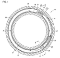
図1~図3を参照して、本実施形態に係る軸受装置を説明する。本実施形態に係る軸受装置10は、転がり軸受装置であって、転がり軸受である軸受11(図2参照)と、潤滑油供給ユニット20(図2参照)とを備える。潤滑油供給ユニット20は、軸受11の軸方向の一端部に突き当てられた外輪間座33と内輪間座34との間に組み込まれている。軸受11と潤滑油供給ユニット20とを備える軸受装置10は、機械装置のたとえば回転軸とハウジングとの間に組み込まれて使用される。機械装置に上記軸受装置10が組込まれる場合、たとえば軸受11の他端部にも他の間座を突き当ててもよい。この場合、上記外輪間座33と内輪間座34および他の間座によって軸受11の軸方向の位置決めを行うことができる。 <Configuration of bearing device>
A bearing device according to this embodiment will be described with reference to FIGS. Thebearing device 10 according to the present embodiment is a rolling bearing device, and includes a bearing 11 (see FIG. 2) that is a rolling bearing and a lubricating oil supply unit 20 (see FIG. 2). The lubricating oil supply unit 20 is incorporated between an outer ring spacer 33 and an inner ring spacer 34 that are abutted against one end of the bearing 11 in the axial direction. A bearing device 10 including a bearing 11 and a lubricating oil supply unit 20 is used by being incorporated, for example, between a rotating shaft and a housing of a mechanical device. When the bearing device 10 is incorporated in a mechanical device, for example, another spacer may be abutted against the other end of the bearing 11. In this case, the bearing 11 can be positioned in the axial direction by the outer ring spacer 33, the inner ring spacer 34, and other spacers.
図1~図3を参照して、本実施形態に係る軸受装置を説明する。本実施形態に係る軸受装置10は、転がり軸受装置であって、転がり軸受である軸受11(図2参照)と、潤滑油供給ユニット20(図2参照)とを備える。潤滑油供給ユニット20は、軸受11の軸方向の一端部に突き当てられた外輪間座33と内輪間座34との間に組み込まれている。軸受11と潤滑油供給ユニット20とを備える軸受装置10は、機械装置のたとえば回転軸とハウジングとの間に組み込まれて使用される。機械装置に上記軸受装置10が組込まれる場合、たとえば軸受11の他端部にも他の間座を突き当ててもよい。この場合、上記外輪間座33と内輪間座34および他の間座によって軸受11の軸方向の位置決めを行うことができる。 <Configuration of bearing device>
A bearing device according to this embodiment will be described with reference to FIGS. The
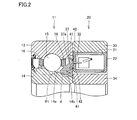
軸受11は、たとえば回転側の軌道輪である内輪14と、たとえば固定側の外輪13と、これらの内輪14と外輪13との間に介在された複数の転動体15と、複数の転動体15を一定間隔に保持する保持器16と、当該保持器16の外周側に配置されたシール部材とを主に備える。軸受11としては、たとえば、アンギュラ玉軸受、深溝玉軸受、あるいは円筒ころ軸受などを用いることができる。軸受11には、予め所望のグリースが封入される。上記シール部材は、外輪間座33などが配置された側と反対側の端部に配置される。
The bearing 11 includes, for example, an inner ring 14 which is a rotating raceway ring, a fixed outer ring 13, a plurality of rolling elements 15 interposed between the inner ring 14 and the outer ring 13, and a plurality of rolling elements 15. Is mainly provided with a retainer 16 that holds a fixed distance at a predetermined interval and a seal member that is disposed on the outer peripheral side of the retainer 16. As the bearing 11, for example, an angular ball bearing, a deep groove ball bearing, or a cylindrical roller bearing can be used. The bearing 11 is filled with desired grease in advance. The seal member is disposed at the end opposite to the side where the outer ring spacer 33 or the like is disposed.
軸受11の内輪14では、外周面に転動体15が接触する内輪転走面が形成されている。また、外周面は当該内輪転走面に連なる傾斜部14aを含む。傾斜部14aは、内輪14の軸方向における端部から内輪転走面に向かうにつれて外輪13に近づくように、軸方向に対して傾斜している。傾斜部14aの軸方向に対する傾斜角度θ1は、たとえば5°以上45°以下である。また、当該傾斜角度θ1の下限は、10°であってもよい。また、傾斜角度θ1の上限は、40°であってもよく、35°であってもよい。
In the inner ring 14 of the bearing 11, an inner ring rolling surface with which the rolling element 15 contacts is formed on the outer circumferential surface. Further, the outer peripheral surface includes an inclined portion 14a connected to the inner ring rolling surface. The inclined portion 14a is inclined with respect to the axial direction so as to approach the outer ring 13 from the end in the axial direction of the inner ring 14 toward the inner ring rolling surface. The inclination angle θ1 with respect to the axial direction of the inclined portion 14a is, for example, not less than 5 ° and not more than 45 °. Further, the lower limit of the inclination angle θ1 may be 10 °. Further, the upper limit of the inclination angle θ1 may be 40 ° or 35 °.
傾斜部14aには、凹部14bが形成されている。凹部14bは、軸受11の周方向に伸びる円周溝である。凹部14bの深さはたとえば0.1mm以上2mm以下である。凹部14bの深さの下限は0.2mmであってもよく、0.3mmであってもよい。凹部14bの深さの上限は1.8mmであってもよく、1.5mmであってもよく、1.0mmであってもよい。また、軸受11の軸方向に沿った断面における凹部14bの形状は、半円状であってもよく、V字状であってもよい。上記断面における凹部14bの形状は、曲線を含んでいてもよいが、直線を含んでいてもよい。
A concave portion 14b is formed in the inclined portion 14a. The recess 14 b is a circumferential groove extending in the circumferential direction of the bearing 11. The depth of the recess 14b is, for example, not less than 0.1 mm and not more than 2 mm. The lower limit of the depth of the recess 14b may be 0.2 mm or 0.3 mm. The upper limit of the depth of the recess 14b may be 1.8 mm, 1.5 mm, or 1.0 mm. Moreover, the shape of the recessed part 14b in the cross section along the axial direction of the bearing 11 may be semicircular, and may be V-shaped. The shape of the recess 14b in the cross section may include a curved line or may include a straight line.
内輪間座34と外輪間座33とから間座が構成されている。内輪間座34は内輪14の一方の端面に突き当てられる。外輪間座33は外輪13の一方の端面に突き当てられる。
The inner ring spacer 34 and the outer ring spacer 33 constitute a spacer. The inner ring spacer 34 is abutted against one end face of the inner ring 14. The outer ring spacer 33 is abutted against one end face of the outer ring 13.
潤滑油供給ユニット20は、円環状のハウジング内において円周方向に配置された、発電部25、電源回路26、制御回路27、駆動回路28、ポンプ29、潤滑油タンク30を主に備える。電源回路26は充電部を含んでいてもよい。潤滑油タンク30は、軸受11に封入されているグリースの基油と同じ種類の潤滑油を貯留する。発電部25、電源回路26、制御回路27、駆動回路28、ポンプ29、潤滑油タンク30は、ハウジング本体21内部において、円周方向に並ぶように配置されている。発電部25は電源回路26に接続されている。電源回路26は制御回路27に接続されている。制御回路27は駆動回路28に接続されている。駆動回路28はマイクロポンプなどのポンプ29を動作させるための回路である。駆動回路28に接続されたポンプ29には、潤滑油タンク30の袋体に接続された吸込みチューブ31と、当該ポンプ29から軸受11の内部に潤滑油を供給するための吐出チューブ32とが接続されている。
The lubricating oil supply unit 20 mainly includes a power generation unit 25, a power circuit 26, a control circuit 27, a driving circuit 28, a pump 29, and a lubricating oil tank 30 that are arranged in a circumferential direction in an annular housing. The power supply circuit 26 may include a charging unit. The lubricating oil tank 30 stores the same type of lubricating oil as the base oil of the grease sealed in the bearing 11. The power generation unit 25, the power supply circuit 26, the control circuit 27, the drive circuit 28, the pump 29, and the lubricating oil tank 30 are arranged in the circumferential direction in the housing body 21. The power generation unit 25 is connected to the power supply circuit 26. The power supply circuit 26 is connected to the control circuit 27. The control circuit 27 is connected to the drive circuit 28. The drive circuit 28 is a circuit for operating a pump 29 such as a micropump. Connected to the pump 29 connected to the drive circuit 28 are a suction tube 31 connected to the bag body of the lubricating oil tank 30 and a discharge tube 32 for supplying lubricating oil from the pump 29 to the inside of the bearing 11. Has been.
吐出チューブ32の先端部(ポンプ29と接続された根元部と反対側の端部)には、図2に示すようにノズル部材37が接続されている。ノズル部材37には、吐出チューブ32に繋がるノズル孔37aが形成されている。
A nozzle member 37 is connected to the distal end of the discharge tube 32 (the end opposite to the root connected to the pump 29) as shown in FIG. A nozzle hole 37 a connected to the discharge tube 32 is formed in the nozzle member 37.
ノズル部材37は、潤滑油供給ユニット20の円環状のハウジングに接続されている。潤滑油供給ユニット20の円環状のハウジングは、図2に示すように、軸受11と反対側の面が開放された断面がカップ形状のハウジング本体21と、このハウジング本体21の開口部を閉塞し、ハウジング本体21に対して着脱自在の蓋体22とによって構成される。ノズル部材37は、ハウジング本体21における軸受11に対向する面に接続されている。また、ノズル部材37においてハウジング本体21に接続される面には、ノズル孔37aを囲むように環状のシール用溝41が形成されている。シール用溝41の内部にはシール部材42が配置されている。当該シール部材42は、吐出チューブ32からノズル孔37aに供給される潤滑油がノズル部材37とハウジング本体21との接合面から外部へ漏れることを防止するために設置されている。
The nozzle member 37 is connected to the annular housing of the lubricating oil supply unit 20. As shown in FIG. 2, the annular housing of the lubricating oil supply unit 20 has a cup-shaped housing main body 21 with the surface opposite to the bearing 11 open, and closes the opening of the housing main body 21. The lid body 22 is detachably attached to the housing body 21. The nozzle member 37 is connected to a surface of the housing body 21 that faces the bearing 11. An annular sealing groove 41 is formed on a surface of the nozzle member 37 connected to the housing body 21 so as to surround the nozzle hole 37a. A sealing member 42 is disposed inside the sealing groove 41. The seal member 42 is installed to prevent the lubricating oil supplied from the discharge tube 32 to the nozzle hole 37 a from leaking to the outside from the joint surface between the nozzle member 37 and the housing body 21.
ノズル部材37は、軸受11の内輪14における傾斜部14aに対向する表面部分を含む。ノズル孔37aの先端部は、当該表面部分形成された開口部であって、傾斜部14aに面するように形成されている。また、ノズル孔37aの先端部は、傾斜部14aの凹部14bと対向する位置に配置されている。凹部14bの位置は、内輪転走面に隣接する位置(たとえば保持器16の軸方向端部より内輪転走面寄りの位置)であってもよい。また、ノズル部材37の傾斜部14aに対向する表面は、内輪14の端部から内輪転走面に隣接する位置(たとえば保持器16の軸方向端部より内輪転走面寄りの位置)にまで伸びていてもよい。
The nozzle member 37 includes a surface portion that faces the inclined portion 14 a of the inner ring 14 of the bearing 11. The tip of the nozzle hole 37a is an opening formed in the surface portion, and is formed so as to face the inclined portion 14a. The tip of the nozzle hole 37a is disposed at a position facing the recess 14b of the inclined portion 14a. The position of the recess 14b may be a position adjacent to the inner ring rolling surface (for example, a position closer to the inner ring rolling surface than the axial end of the cage 16). The surface of the nozzle member 37 facing the inclined portion 14a extends from the end of the inner ring 14 to a position adjacent to the inner ring rolling surface (for example, a position closer to the inner ring rolling surface than the axial end of the cage 16). It may be stretched.
なお、ノズル部材37のノズル孔の内径dは、基油の粘度に起因する表面張力と吐出量との関係により、適宜設定できる。また、ノズル部材37の傾斜部14aに対向する表面と当該傾斜部14aとの間の距離も、基油の粘土などを考慮し、ノズル部材37の当該表面と傾斜部14aとの間の隙間を毛細管現象により基油が転動体15側へ容易に流動できるように、適宜設定することができる。当該距離は、たとえば0.1mm以上1mm以下とすることができる。当該距離の下限は0.2mmであってもよく、0.3mmであってもよい。当該距離の上限は0.9mmであってもよく、0.7mmであってもよく、0.6mmであってもよい。
Note that the inner diameter d of the nozzle hole of the nozzle member 37 can be appropriately set according to the relationship between the surface tension resulting from the viscosity of the base oil and the discharge amount. In addition, the distance between the surface of the nozzle member 37 facing the inclined portion 14a and the inclined portion 14a also takes into account the gap between the surface of the nozzle member 37 and the inclined portion 14a in consideration of clay of the base oil. It can be set as appropriate so that the base oil can easily flow to the rolling element 15 side by capillary action. The distance can be, for example, not less than 0.1 mm and not more than 1 mm. The lower limit of the distance may be 0.2 mm or 0.3 mm. The upper limit of the distance may be 0.9 mm, 0.7 mm, or 0.6 mm.
図1に示す制御回路27は、たとえば潤滑油供給ユニット20における潤滑油の供給状況に関するデータを取得するとともに、当該データを制御回路27の外部へ(たとえば受信部としての出力基板56(図5参照)へ)出力可能になっている。
The control circuit 27 shown in FIG. 1 acquires, for example, data relating to the lubricant supply status in the lubricant supply unit 20, and sends the data to the outside of the control circuit 27 (for example, an output board 56 as a receiving unit (see FIG. 5). )) Output is enabled.
潤滑油供給ユニット20の発電部25としては、例えば、ゼーベック効果によって発電を行うものを使用することができる。具体的には、発電部25は、外輪間座33に接続された熱伝導体23aと、内輪間座34に配置された熱伝導体23bと、熱伝導体23aと熱伝導体23bとの間を接続するように配置され、熱伝導体23a、23bと密着固定された熱電素子24(ペルチェ素子のゼーベック効果を利用した素子)とを有する。
As the power generation unit 25 of the lubricating oil supply unit 20, for example, a unit that generates power by the Seebeck effect can be used. Specifically, the power generation unit 25 includes a heat conductor 23a connected to the outer ring spacer 33, a heat conductor 23b disposed in the inner ring spacer 34, and a space between the heat conductor 23a and the heat conductor 23b. The thermoelectric elements 24 (elements using the Seebeck effect of Peltier elements) are disposed so as to be connected to each other, and are closely fixed to the heat conductors 23a and 23b.
ここで、図2に示すように軸受装置10として転がり軸受装置を使用する場合、転動体15(図2参照)との摩擦熱により内輪14と外輪13の温度が上昇する。通常、外輪13は機器のハウジングに組み込まれるため熱伝導により放熱される。そのため、内輪14と外輪13との間で温度差が生じる(外輪13の温度に対して内輪14の温度の方が高い)。その温度が各熱伝導体23a、23bに伝導される。熱伝導体23a、23bは、それぞれハウジング本体21の内周面と外周面とを貫通するように配置されている。そのため、外輪間座33を介して外輪13と接続された熱伝導体23a(ヒートシンク)と、内輪間座34側(内輪14側)に位置する熱伝導体23bとの間に配置された熱電素子24の両端面には温度差が生じる。このため、熱電素子24ではゼーベック効果により発電を行うことができる。このような発電部25を用いることにより、外部から潤滑油供給ユニットに電力を供給する必要がないため、工作機用スピンドル50へ外部から電力を供給するための電線を取り付ける必要がない。
Here, when a rolling bearing device is used as the bearing device 10 as shown in FIG. 2, the temperature of the inner ring 14 and the outer ring 13 rises due to frictional heat with the rolling elements 15 (see FIG. 2). Normally, the outer ring 13 is dissipated by heat conduction because it is incorporated in the housing of the device. Therefore, a temperature difference occurs between the inner ring 14 and the outer ring 13 (the temperature of the inner ring 14 is higher than the temperature of the outer ring 13). The temperature is conducted to each heat conductor 23a, 23b. The heat conductors 23a and 23b are disposed so as to penetrate the inner peripheral surface and the outer peripheral surface of the housing body 21, respectively. Therefore, a thermoelectric element disposed between the heat conductor 23a (heat sink) connected to the outer ring 13 via the outer ring spacer 33 and the heat conductor 23b located on the inner ring spacer 34 side (inner ring 14 side). A temperature difference occurs between both end faces of 24. For this reason, the thermoelectric element 24 can generate power by the Seebeck effect. By using such a power generation unit 25, it is not necessary to supply power to the lubricating oil supply unit from the outside, and therefore it is not necessary to attach an electric wire for supplying power to the machine tool spindle 50 from the outside.
ハウジング本体21の外周面を貫通する熱伝導体23aにおいて外輪間座33の内周面に接する面には、熱導電性を考慮した接着剤を使用することが好ましい。なお、外輪13側の熱伝導体23aの外周面の曲率半径は、外輪間座33の内周面の曲率半径と実質的に同一にすることが好ましい。このようにすれば、外輪間座33の内周面と熱伝導体23aの外周面とを密着させることができるので、熱伝導体23aと外輪間座33および外輪13との間で熱を効率的に伝えることができる。一方、内輪側の熱伝導体23bの内周面(内輪間座34と対向する面)は、内輪間座34とは接していない。可能であれば、外輪側と内輪側の熱伝導体23a、23bの体積を等しくすることが望ましい。また、内輪側の熱伝導体23bの表面積を大きくすることが望ましい。
It is preferable to use an adhesive in consideration of thermal conductivity on the surface in contact with the inner peripheral surface of the outer ring spacer 33 in the heat conductor 23a penetrating the outer peripheral surface of the housing body 21. The radius of curvature of the outer peripheral surface of the heat conductor 23a on the outer ring 13 side is preferably substantially the same as the radius of curvature of the inner peripheral surface of the outer ring spacer 33. In this way, since the inner peripheral surface of the outer ring spacer 33 and the outer peripheral surface of the heat conductor 23a can be brought into close contact with each other, heat is efficiently transmitted between the heat conductor 23a and the outer ring spacer 33 and the outer ring 13. Can communicate. On the other hand, the inner peripheral surface (surface facing the inner ring spacer 34) of the heat conductor 23b on the inner ring side is not in contact with the inner ring spacer 34. If possible, it is desirable to make the volume of the heat conductors 23a, 23b on the outer ring side and the inner ring side equal. Further, it is desirable to increase the surface area of the heat conductor 23b on the inner ring side.
なお、外輪間座33の内周面と熱伝導体23aとの間、熱伝導体23aと熱電素子24との間、熱電素子24と内輪側の熱伝導体23bとの間には、熱伝導率及び密着性を高めるため、放熱グリースなどを塗布することが好ましい。放熱グリースは、一般的にシリコーンが主成分である。また、熱伝導体23a、23bの材料としては、熱伝導率の高い金属を使用することが好ましい。例えば、銀(Ag)、銅(Cu)、金(Au)などを用いることができるが、コスト面から銅を使用することが好ましい。なお、熱伝導体23a、23bの材料として銅を主成分とする銅合金を用いてもよく、銅を主成分とする焼結合金を用いてもよい。また、熱電素子24に接続される熱伝導体は高温側のみに配置され、低温側については間座(外輪間座33)に熱電素子24を密着固定してもよい。
Note that heat conduction between the inner peripheral surface of the outer ring spacer 33 and the heat conductor 23a, between the heat conductor 23a and the thermoelectric element 24, and between the thermoelectric element 24 and the heat conductor 23b on the inner ring side. In order to increase the rate and adhesion, it is preferable to apply a heat dissipating grease or the like. Generally, the heat dissipating grease is mainly composed of silicone. Moreover, it is preferable to use a metal with high heat conductivity as a material of the heat conductors 23a and 23b. For example, silver (Ag), copper (Cu), gold (Au) or the like can be used, but it is preferable to use copper from the viewpoint of cost. In addition, as a material of the heat conductors 23a and 23b, a copper alloy containing copper as a main component may be used, or a sintered alloy containing copper as a main component may be used. In addition, the heat conductor connected to the thermoelectric element 24 may be disposed only on the high temperature side, and the thermoelectric element 24 may be tightly fixed to the spacer (outer ring spacer 33) on the low temperature side.
発電部25によって発生した(発電された)電荷は、電源回路26に蓄電される。具体的には、当該電荷は電源回路26(蓄電回路とも呼ぶ)に含まれる蓄電池やコンデンサなどの蓄電部に蓄電される。コンデンサとしては、電気二重層コンデンサ(キャパシタ)を使用することが好ましい。
The electric charge generated (generated) by the power generation unit 25 is stored in the power supply circuit 26. Specifically, the electric charge is stored in a power storage unit such as a storage battery or a capacitor included in the power supply circuit 26 (also referred to as a power storage circuit). As a capacitor, it is preferable to use an electric double layer capacitor (capacitor).
制御回路27は、駆動回路28を介してポンプ29の動作を制御するための制御部であって、制御プログラムが保持されるプログラム記憶部および当該プログラム記憶部と接続され当該制御プログラムを実行する演算部(マイコン)とを含む。制御回路27により、軸受11への潤滑油の供給開始時期、供給タイミング(インターバル)、潤滑油の供給のためのポンプ29の駆動時間、潤滑油の供給量などを予め設定することができる。そして、このように潤滑油の供給状態を適切に保つことにより、軸受装置の潤滑寿命を延ばすことができる。
The control circuit 27 is a control unit for controlling the operation of the pump 29 via the drive circuit 28, and is a program storage unit that holds a control program and an arithmetic operation that is connected to the program storage unit and executes the control program Part (microcomputer). By the control circuit 27, the supply start timing of lubricant oil to the bearing 11, the supply timing (interval), the driving time of the pump 29 for supplying lubricant, the supply amount of lubricant, and the like can be set in advance. And the lubrication life of a bearing apparatus can be extended by maintaining the supply state of lubricating oil appropriately in this way.
駆動部としての駆動回路28は、例えば、任意のセンサ(軸受温度センサ、軸受回転センサ、潤滑油残量センサ、潤滑油温度センサ等)を備えていてもよい。これらのセンサからの信号が駆動回路28の演算部(マイコン)に入力され、軸受11の温度及びその回転状況に応じてポンプ29を自動制御し、潤滑油の供給量を調整してもよい。
The drive circuit 28 as the drive unit may include, for example, an arbitrary sensor (a bearing temperature sensor, a bearing rotation sensor, a remaining amount of lubricant sensor, a lubricant temperature sensor, etc.). Signals from these sensors may be input to a calculation unit (microcomputer) of the drive circuit 28, and the pump 29 may be automatically controlled in accordance with the temperature of the bearing 11 and its rotation state to adjust the supply amount of the lubricating oil.
ポンプ29は駆動回路28を介して制御回路27により制御される。ポンプ29は、潤滑油タンク30内の潤滑油を吸込みチューブ31から吸引し、吸引した潤滑油を吐出チューブ32およびノズル孔37aを介して軸受11の内部へ供給する。
The pump 29 is controlled by the control circuit 27 via the drive circuit 28. The pump 29 sucks the lubricating oil in the lubricating oil tank 30 from the suction tube 31, and supplies the sucked lubricating oil to the inside of the bearing 11 through the discharge tube 32 and the nozzle hole 37a.
潤滑油供給ユニット20の円環状のハウジングを構成するハウジング本体21と蓋体22とは、任意の材料により構成してもよいが、たとえば樹脂材料、より好ましくは熱可塑性樹脂により構成してもよい。上記ハウジングを構成する材料としては、たとえばポリフェニレンサルファイド(PPS)等を用いることができる。また、ハウジング本体21と蓋体22とは同種の材料により構成されてもよいが、異なる材料により構成してもよい。
The housing main body 21 and the lid 22 constituting the annular housing of the lubricating oil supply unit 20 may be made of any material, but may be made of, for example, a resin material, more preferably a thermoplastic resin. . As a material constituting the housing, for example, polyphenylene sulfide (PPS) can be used. The housing body 21 and the lid body 22 may be made of the same kind of material, but may be made of different materials.
ハウジングの蓋体22は、ハウジング本体21に対し、固定部材の一例としてのネジにより固定されてもよい。蓋体22をハウジング本体21に固定することにより、ハウジング本体21と蓋体22とにより囲まれたハウジング内部を密閉することができる。なお、固定部材としてのネジが固定されているタップ穴35から当該ネジを外して、蓋体22を取り除くことができる。このようにすれば、潤滑油供給ユニット20全体を軸受装置10から取外すことなく、ハウジング本体21内に収納されている潤滑油タンク30に、潤滑油を補充することができる。
The housing lid 22 may be fixed to the housing main body 21 with a screw as an example of a fixing member. By fixing the lid body 22 to the housing body 21, the inside of the housing surrounded by the housing body 21 and the lid body 22 can be sealed. The lid 22 can be removed by removing the screw from the tap hole 35 to which the screw as the fixing member is fixed. In this way, the lubricating oil can be replenished to the lubricating oil tank 30 housed in the housing body 21 without removing the entire lubricating oil supply unit 20 from the bearing device 10.
ハウジング本体21の外周面は、外輪間座33の内周面に固定されていてもよい。当該ハウジング本体21の外周面と外輪間座33との間はたとえば接着剤によって接着固定されていてもよい。ハウジング本体21を接着固定する接着剤は、たとえばエポキシ樹脂等を使用してもよい。なお、ハウジング本体21(つまり潤滑油供給ユニット20)は軸受11の静止輪に固定されていてもよい。なお、ハウジング本体21と内輪間座34との間には隙間36が形成されていてもよい。
The outer peripheral surface of the housing body 21 may be fixed to the inner peripheral surface of the outer ring spacer 33. The outer peripheral surface of the housing main body 21 and the outer ring spacer 33 may be bonded and fixed by, for example, an adhesive. For example, an epoxy resin or the like may be used as an adhesive for bonding and fixing the housing body 21. The housing body 21 (that is, the lubricating oil supply unit 20) may be fixed to the stationary ring of the bearing 11. A gap 36 may be formed between the housing main body 21 and the inner ring spacer 34.
次に、ハウジング本体21内に収納する潤滑油タンク30は、柔軟性を有する樹脂製の袋体により構成してもよい。潤滑油タンク30は、円環状のハウジング本体21に沿って円弧状に配置されていてもよい。
Next, the lubricating oil tank 30 housed in the housing body 21 may be formed of a flexible resin bag. The lubricating oil tank 30 may be arranged in an arc shape along the annular housing body 21.
潤滑油タンク30を構成する樹脂製の袋体は、例えば、樹脂シートを重ね、外周部を熱溶着して形成して構成してもよい。潤滑油タンク30の外周部が熱溶着された部分となっていてもよい。
The resin bag constituting the lubricating oil tank 30 may be formed by, for example, stacking resin sheets and thermally welding the outer periphery. The outer peripheral part of the lubricating oil tank 30 may be a heat-welded part.
潤滑油タンク30の袋体には、ポンプ29と接続する吸込みチューブ31を設ける。吸込みチューブ31は、潤滑油タンク30の袋体を熱溶着により形成する際に、当該袋体を形成するために重ね合わせた樹脂シートの間に挟み込んで熱溶着する。このようにして、吸込みチューブ31を袋体と一体化することができる。
The suction tube 31 connected to the pump 29 is provided in the bag body of the lubricating oil tank 30. When the bag body of the lubricating oil tank 30 is formed by heat welding, the suction tube 31 is sandwiched between the stacked resin sheets to form the bag body and heat-welded. In this way, the suction tube 31 can be integrated with the bag.
なお、潤滑油タンク30を構成する袋体の構成としては、他の任意の構成を採用することができる。たとえば、袋体をブロー成形により形成してもよい。この場合、吸込みチューブ31を袋体と一体にブロー成形してもよい。また、潤滑油タンク30の袋体を上記のようにブロー成形すると、袋体が膨らんだ形状(袋状)になるため、当該袋体を成形後、袋状の部分を平たく成形することが望ましい。袋状の部分を平たく成形することにより、潤滑油の量が少なくなっても、潤滑油タンク30から潤滑油を最後まで吐出することができる。すなわち、潤滑油タンク30内の潤滑油をほとんど使い切ることができる。
In addition, as a structure of the bag body which comprises the lubricating oil tank 30, other arbitrary structures are employable. For example, the bag body may be formed by blow molding. In this case, the suction tube 31 may be blow-molded integrally with the bag. Further, when the bag body of the lubricating oil tank 30 is blow-molded as described above, the bag body is in an expanded shape (bag shape). Therefore, it is desirable to form the bag-like portion flat after the bag body is molded. . By forming the bag-like portion flat, the lubricating oil can be discharged from the lubricating oil tank 30 to the end even if the amount of the lubricating oil is reduced. That is, the lubricating oil in the lubricating oil tank 30 can be almost used up.
潤滑油タンク30を形成する袋体の素材は、任意の材料を用いることができるが、たとえば樹脂材料を用いることが好ましい。潤滑油タンク30の材料としては、たとえばナイロン、ポリエチレン、ポリエステル、ポリプロピレンなどを用いることができるが、袋体内に収容される潤滑油に対する耐久性を有する材料であれば特に限定されない。
Any material can be used as the material of the bag forming the lubricating oil tank 30, but it is preferable to use, for example, a resin material. As a material of the lubricating oil tank 30, for example, nylon, polyethylene, polyester, polypropylene or the like can be used, but there is no particular limitation as long as it is a material having durability against the lubricating oil stored in the bag.
潤滑油タンク30の袋体に設ける吸込みチューブ31は、ポンプ29に対して取り外し可能に接続されていてもよい。吸込みチューブ31をポンプ29に対して取り外し可能にすることで、潤滑油タンク30内の潤滑油の残量がなくなった場合に、吸込みチューブ31をポンプ29から外し、吸込みチューブ31から袋体内に潤滑油を補充することができる。
The suction tube 31 provided in the bag body of the lubricating oil tank 30 may be detachably connected to the pump 29. By making the suction tube 31 detachable from the pump 29, when the remaining amount of lubricating oil in the lubricating oil tank 30 runs out, the suction tube 31 is removed from the pump 29 and lubricated from the suction tube 31 into the bag body. Oil can be replenished.
また、ポンプ29に対して潤滑油タンク30の袋体を取り外し可能にしておくことで、潤滑油を充填した予備の袋体を準備しておき、当該袋体を交換することができる。たとえば、使用中の潤滑油タンク30内の潤滑油がなくなったときに、使用済みの潤滑油タンク30の袋体を取り外し、予備の袋体(潤滑油が内部に充填された袋体)に交換することにより、潤滑油供給ユニット20における潤滑油の補充を短時間で行うことができる。
Further, by making the bag body of the lubricating oil tank 30 removable with respect to the pump 29, a spare bag body filled with lubricating oil can be prepared and the bag body can be exchanged. For example, when the lubricating oil in the used lubricating oil tank 30 runs out, remove the used lubricating oil tank 30 bag and replace it with a spare bag (a bag filled with lubricating oil). By doing so, the lubricating oil supply unit 20 can be replenished in a short time.
また、上述した予備の袋体への潤滑油の充填は、潤滑油製造メーカなどにおいて管理された状態で実施できる。このようにすれば、袋体内への異物の侵入といった充填時における不具合の発生確率を低減できる。なお、予備の袋体を保管しているときには、予備の袋体の吸込みチューブ31に蓋を装着しておくことが好ましい。このようにすれば、保管中の袋体の内部に異物が混入することを防止できる。
Also, the above-described spare bag body can be filled with lubricating oil in a state managed by a lubricating oil manufacturer or the like. In this way, it is possible to reduce the probability of occurrence of problems during filling, such as the entry of foreign matter into the bag. In addition, when the spare bag body is stored, it is preferable to attach a lid to the suction tube 31 of the spare bag body. If it does in this way, it can prevent that a foreign material mixes in the inside of the bag body in storage.
なお、上記の軸受装置は内輪回転である。また、回転中心を横軸としたが、縦軸としてもよい。
Note that the bearing device described above is an inner ring rotation. Further, although the rotation center is the horizontal axis, it may be the vertical axis.
<軸受装置の動作>
軸受11および潤滑油供給ユニット20を含む軸受装置10では、制御回路27によりポンプ29の動作を制御することにより、潤滑油タンク30から軸受11に潤滑油を供給することができる。 <Operation of bearing device>
In thebearing device 10 including the bearing 11 and the lubricant supply unit 20, the lubricant can be supplied from the lubricant tank 30 to the bearing 11 by controlling the operation of the pump 29 by the control circuit 27.
軸受11および潤滑油供給ユニット20を含む軸受装置10では、制御回路27によりポンプ29の動作を制御することにより、潤滑油タンク30から軸受11に潤滑油を供給することができる。 <Operation of bearing device>
In the
そして、ノズル部材37のノズル孔37aを介して軸受11の内部に供給された潤滑油は、まず傾斜部14aの凹部14b内にいったん貯留される。その後、内輪14の回転による遠心力により、内輪14の傾斜部14aとノズル部材37の表面との間の隙間に当該潤滑油が流動する。そして、上記遠心力(および毛細管現象)によって、当該隙間を転動体15側に向かって潤滑油が流動する。このようにして、軸受11の内部に供給された潤滑油は転動体15と内輪14および外輪13との接触部へ供給される。この結果、軸受11の潤滑性能を長期間維持することができる。
The lubricating oil supplied to the inside of the bearing 11 through the nozzle hole 37a of the nozzle member 37 is first temporarily stored in the recess 14b of the inclined portion 14a. Thereafter, the lubricating oil flows into the gap between the inclined portion 14 a of the inner ring 14 and the surface of the nozzle member 37 due to the centrifugal force generated by the rotation of the inner ring 14. Then, due to the centrifugal force (and capillary action), the lubricating oil flows through the gap toward the rolling element 15 side. In this way, the lubricating oil supplied to the inside of the bearing 11 is supplied to the contact portion between the rolling element 15 and the inner ring 14 and the outer ring 13. As a result, the lubrication performance of the bearing 11 can be maintained for a long time.
なお、ポンプ29の駆動のタイミングは、発電部25で発生した電力が電源回路26における蓄電部(たとえばコンデンサ)に蓄電され、当該蓄電部の電圧が一定の電圧に達した時点で行なうことが可能である。さらに、グリースを封入した軸受11の潤滑寿命を長くし、メンテナンスまでの時間を長くするために、ポンプ29を所定のインターバル時間が経過した時点毎に駆動することが望ましい。
The driving timing of the pump 29 can be performed when the power generated in the power generation unit 25 is stored in a power storage unit (for example, a capacitor) in the power supply circuit 26 and the voltage of the power storage unit reaches a certain voltage. It is. Further, in order to extend the lubrication life of the bearing 11 filled with grease and to increase the time until maintenance, it is desirable to drive the pump 29 every time a predetermined interval time has elapsed.
例えば、ポンプ29を駆動するために必要な電圧に蓄電部の電圧が達する(あるいは満充電になる)までの充電時間が、必要とする潤滑油の供給タイミングよりも早い場合には、蓄電部の電圧が所定の電圧に達した(つまり満充電状態に達した)時点t1の後も、所定時間の蓄電時間(遅延時間)を加えて(つまり時点t1から時点t2までの遅延時間を加えて)、時点t2において蓄電部に蓄積された電力によりポンプ29を駆動する。このようにして、蓄電部の電圧が所定の電圧(たとえば満充電)に達する時間より、潤滑油の供給インターバルを長くするように管理できる。
For example, if the charging time until the voltage of the power storage unit reaches the voltage necessary for driving the pump 29 (or full charge) is earlier than the required supply timing of the lubricating oil, After the time t1 when the voltage reaches the predetermined voltage (that is, when the fully charged state is reached), a predetermined accumulation time (delay time) is added (that is, a delay time from the time t1 to the time t2 is added). Then, the pump 29 is driven by the electric power stored in the power storage unit at time t2. In this way, it is possible to manage the supply interval of the lubricating oil to be longer than the time when the voltage of the power storage unit reaches a predetermined voltage (for example, full charge).
<機械装置の構成>
図4および図5を参照して、本実施形態に係る軸受装置を適用した機械装置の一例である工作機用スピンドルの構成を説明する。 <Configuration of mechanical device>
With reference to FIG. 4 and FIG. 5, the structure of the spindle for machine tools which is an example of the mechanical apparatus to which the bearing apparatus which concerns on this embodiment is applied is demonstrated.
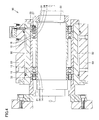
図4および図5に示すように、本実施形態に係る工作機用スピンドル50は、回転軸51と、当該回転軸51の周囲を囲むように配置されたスピンドルハウジング52と、当該スピンドルハウジング52の外周に配置された外周ハウジング53と、回転軸51をスピンドルハウジング52に対して回転可能に保持する軸受装置とを主に備える。回転軸51の外周には2つの軸受装置が配置されている。軸受装置における軸受の内輪14および内輪間座34が回転軸51の側面に嵌合固定されている。また、軸受の外輪13および外輪間座33がスピンドルハウジング52の内周面に嵌合固定されている。なお、上記内輪14、外輪13および当該内輪14と外輪13との間に配置された玉である転動体15を含む軸受はアンギュラ玉軸受である。当該軸受に隣接するように配置された内輪間座34および外輪間座33の間には、潤滑油供給ユニット20が配置されている。また、2つの軸受の間(潤滑油供給ユニットが配置された側と反対側)には他の間座が回転軸51およびスピンドルハウジング52に嵌合固定されるとともに、内輪14と外輪13とに突き当てられている。
As shown in FIGS. 4 and 5, the machine tool spindle 50 according to the present embodiment includes a rotating shaft 51, a spindle housing 52 arranged so as to surround the rotating shaft 51, and the spindle housing 52. An outer peripheral housing 53 disposed on the outer periphery and a bearing device that rotatably holds the rotating shaft 51 with respect to the spindle housing 52 are mainly provided. Two bearing devices are arranged on the outer periphery of the rotating shaft 51. The inner ring 14 and the inner ring spacer 34 of the bearing in the bearing device are fitted and fixed to the side surface of the rotating shaft 51. Further, the outer ring 13 of the bearing and the outer ring spacer 33 are fitted and fixed to the inner peripheral surface of the spindle housing 52. The bearing including the inner ring 14, the outer ring 13 and the rolling elements 15 that are balls arranged between the inner ring 14 and the outer ring 13 is an angular ball bearing. The lubricating oil supply unit 20 is disposed between the inner ring spacer 34 and the outer ring spacer 33 disposed so as to be adjacent to the bearing. In addition, between the two bearings (on the side opposite to the side where the lubricating oil supply unit is disposed), other spacers are fitted and fixed to the rotating shaft 51 and the spindle housing 52, and are connected to the inner ring 14 and the outer ring 13. It has been hit.
潤滑油供給ユニットの制御回路27と対向する領域には、ハウジング本体21(図2参照)、外輪間座33、スピンドルハウジング52および外周ハウジング53を貫通する貫通穴が形成されている。この貫通穴の外周側端部には、外周ハウジング53の表面に平面部が設けられ、当該平面部上に台座57が配置されている。当該台座57上に出力基板56が配置されている。出力基板56と潤滑油供給ユニット20の制御回路27とは、たとえばコンタクトプローブ54により電気的に接続されている。コンタクトプローブ54は上記貫通穴の内部に配置されている。コンタクトプローブ54の一方端は制御回路27の電極パッド(図示せず)に接触するとともに、コンタクトプローブ54の他方端は導電線55により出力基板56と接続されている。コンタクトプローブ54は出力基板56側に接続固定されていてもよい。また、出力基板56と制御回路27とは、上記のように有線接続されていてもよいが、他の接続手段(たとえば発光素子と受光素子とを用いた光通信手段など)を用いて接続されていてもよい。
In a region facing the control circuit 27 of the lubricating oil supply unit, a through-hole penetrating the housing main body 21 (see FIG. 2), the outer ring spacer 33, the spindle housing 52 and the outer peripheral housing 53 is formed. A flat portion is provided on the surface of the outer peripheral housing 53 at the outer peripheral end portion of the through hole, and a pedestal 57 is disposed on the flat portion. An output board 56 is disposed on the pedestal 57. The output board 56 and the control circuit 27 of the lubricating oil supply unit 20 are electrically connected by, for example, a contact probe 54. The contact probe 54 is disposed inside the through hole. One end of the contact probe 54 contacts an electrode pad (not shown) of the control circuit 27, and the other end of the contact probe 54 is connected to the output substrate 56 by a conductive line 55. The contact probe 54 may be connected and fixed to the output substrate 56 side. The output board 56 and the control circuit 27 may be connected by wire as described above, but are connected using other connection means (for example, optical communication means using a light emitting element and a light receiving element). It may be.
台座57上に配置された出力基板56を覆うように、カバー部材58が台座57に固定されている。出力基板56上には、出力基板56の回路を駆動するための電源である電池と、記憶部とが配置されている。電池としては、たとえばコイン型電池やボタン型電池を用いることができる。電池としてリチウム電池を用いることが望ましい。出力基板56の表面にはこのような電池を固定するためのホルダが配置されている。また、記憶部としては、たとえばカード型の外部記憶媒体を接続固定するための保持部(スロット)と当該保持部に着脱可能に固定された外部記憶媒体とを用いることができる。外部記憶媒体としてはメモリカードなど従来周知の任意の記憶媒体を利用できる。
A cover member 58 is fixed to the pedestal 57 so as to cover the output substrate 56 disposed on the pedestal 57. On the output board 56, a battery as a power source for driving the circuit of the output board 56 and a storage unit are arranged. As the battery, for example, a coin battery or a button battery can be used. It is desirable to use a lithium battery as the battery. A holder for fixing such a battery is disposed on the surface of the output substrate 56. Further, as the storage unit, for example, a holding unit (slot) for connecting and fixing a card-type external storage medium and an external storage medium fixed to the holding unit in a removable manner can be used. As the external storage medium, any conventionally known storage medium such as a memory card can be used.
カバー部材58は、台座57との接続部材である固定ボルトを緩めるだけで台座57から取り外せるように、U字形状の長穴部(固定ボルトを配置する穴)が形成されている。上記電池や外部記憶媒体の交換などは、カバー部材58を台座57から取り外した状態で行うことができる。
The cover member 58 is formed with a U-shaped long hole (a hole in which the fixing bolt is disposed) so that the cover member 58 can be removed from the pedestal 57 simply by loosening the fixing bolt as a connecting member to the pedestal 57. The battery and the external storage medium can be replaced with the cover member 58 removed from the pedestal 57.
台座57とカバー部材58とにより密閉された上記出力基板56が電圧監視ユニットの主要部を構成する。台座57とカバー部材58とは、加工機スピンドルを用いた加工時に使用されるクーラントなどの侵入を防ぐため、任意の防水構造を付加することができる。防水構造としては、たとえばパッキング、Oリング、コーキング、樹脂モールドなどを用いることができる。
The output board 56 sealed by the pedestal 57 and the cover member 58 constitutes a main part of the voltage monitoring unit. The pedestal 57 and the cover member 58 can be added with an arbitrary waterproof structure in order to prevent intrusion of coolant or the like used during processing using the processing machine spindle. As the waterproof structure, for example, packing, O-ring, caulking, resin mold or the like can be used.
また、上述した工作機用スピンドル50は、上述のように内輪14、外輪13、転動体15を含む軸受11(図2参照)に接続され、制御回路27(図1参照)を有する制御部を含むユニット本体部と、当該制御部と接続線(コンタクトプローブ54)により接続された電圧監視ユニットである外部出力部70とを含む潤滑油供給ユニットを備えている。ユニット本体部は、制御回路27を含む制御部と、発電部25(図1参照)および電源回路26(図1参照)を含む電源部と、電源回路26、駆動回路28およびポンプ29を含む潤滑油供給部と、潤滑油保持部(潤滑油タンク30)とを含む。制御部は電源部および潤滑油供給部と接続され、潤滑油供給部における潤滑油の供給状態を制御するとともに潤滑油の供給状態に関するデータを取得する。当該データとしては、潤滑油の供給タイミングや潤滑油の供給間隔、またポンプ29などを動作させたときの電源回路(具体的には蓄電部)における電圧(蓄電電圧)のデータなどが挙げられる。
Further, the machine tool spindle 50 described above is connected to the bearing 11 (see FIG. 2) including the inner ring 14, the outer ring 13, and the rolling elements 15 as described above, and has a control unit having a control circuit 27 (see FIG. 1). And a lubricating oil supply unit including an external output unit 70 that is a voltage monitoring unit connected to the control unit through a connection line (contact probe 54). The unit main body includes a control unit including a control circuit 27, a power supply unit including a power generation unit 25 (see FIG. 1) and a power supply circuit 26 (see FIG. 1), a lubrication including a power supply circuit 26, a drive circuit 28, and a pump 29. An oil supply part and a lubricating oil holding part (lubricating oil tank 30) are included. The control unit is connected to the power supply unit and the lubricating oil supply unit, controls the supply state of the lubricating oil in the lubricating oil supply unit, and acquires data regarding the supply state of the lubricating oil. Examples of the data include the supply timing of the lubricating oil, the supply interval of the lubricating oil, and data on the voltage (power storage voltage) in the power supply circuit (specifically, the power storage unit) when the pump 29 is operated.
制御部の制御回路27と外部出力部70の出力基板56との接続部の構成としては、任意の構成を採用できるが、たとえば制御回路27に設置された演算部(マイクロコンピュータ)と出力基板56の演算部とが接続線により接続されていてもよい。制御回路27の演算部は配線などにより電源や接地部と接続されている。また、出力基板56では、演算部は電池および記憶部と接続されている。演算部から記憶部へ電圧などのデータを示す信号(制御回路27から伝送された信号)が送信可能になっている。
As a configuration of a connection portion between the control circuit 27 of the control unit and the output board 56 of the external output unit 70, any configuration can be adopted. For example, an arithmetic unit (microcomputer) installed in the control circuit 27 and the output board 56. The calculation unit may be connected by a connection line. The arithmetic unit of the control circuit 27 is connected to a power source or a ground unit by wiring or the like. In the output board 56, the calculation unit is connected to the battery and the storage unit. A signal indicating data such as voltage (a signal transmitted from the control circuit 27) can be transmitted from the calculation unit to the storage unit.
上記のような構成により、出力基板56の記憶部には制御回路27から伝送された潤滑油の供給状況に関するデータが記憶される。当該データが制御回路27から出力基板56へ伝送されるタイミングとしては、任意のタイミングを採用できるが、たとえば制御回路27の記憶部(演算部に含まれる記憶素子または演算部とは独立して制御回路27に設けられている記憶素子など)が当該データで一杯になった時点で、制御回路27から出力基板56へデータを転送してもよい。当該データが電源部の蓄電電圧の時間変化データを含む場合、当該データを出力基板56の記憶部を介して外部記憶媒体に保存し、外部記憶媒体を用いて当該データを外部のコンピュータなどに取り込むことができる。このようにすれば、外部のコンピュータ上で、潤滑油供給ユニットの状況(発電状態やポンプ29の動作状態など)を確認する事ができる。
With the configuration as described above, the storage unit of the output board 56 stores data relating to the supply state of the lubricating oil transmitted from the control circuit 27. Arbitrary timing can be adopted as the timing at which the data is transmitted from the control circuit 27 to the output board 56. The data may be transferred from the control circuit 27 to the output board 56 when the memory element or the like provided in the circuit 27 is filled with the data. When the data includes time change data of the storage voltage of the power supply unit, the data is stored in an external storage medium via the storage unit of the output board 56, and the data is taken into an external computer or the like using the external storage medium. be able to. In this way, it is possible to check the state of the lubricating oil supply unit (power generation state, operation state of the pump 29, etc.) on an external computer.
<機械装置の動作>
図4および図5に示した機械装置の一例である工作機用スピンドル50は、回転軸51が所定の駆動軸に接続されてスピンドルハウジング52に対して回転可能になっている。そして、当該回転軸51を支持する軸受装置では、潤滑油供給ユニットにより軸受11(図2参照)に対して定期的に潤滑油が供給される。このため、当該工作機用スピンドル50の信頼性および耐久性が向上する。 <Machine operation>
Amachine tool spindle 50 which is an example of the mechanical device shown in FIGS. 4 and 5 is configured such that a rotary shaft 51 is connected to a predetermined drive shaft and is rotatable with respect to the spindle housing 52. And in the bearing apparatus which supports the said rotating shaft 51, lubricating oil is regularly supplied with respect to the bearing 11 (refer FIG. 2) by the lubricating oil supply unit. For this reason, the reliability and durability of the machine tool spindle 50 are improved.
図4および図5に示した機械装置の一例である工作機用スピンドル50は、回転軸51が所定の駆動軸に接続されてスピンドルハウジング52に対して回転可能になっている。そして、当該回転軸51を支持する軸受装置では、潤滑油供給ユニットにより軸受11(図2参照)に対して定期的に潤滑油が供給される。このため、当該工作機用スピンドル50の信頼性および耐久性が向上する。 <Machine operation>
A
上述した説明と一部重複する部分もあるが、本発明の実施形態の特徴的な構成を列挙する。
Although there are portions that partially overlap with the above description, the characteristic configurations of the embodiment of the present invention are listed.
本実施形態に係る軸受装置10は、軸受11と、当該軸受11に接続された潤滑油供給ユニット20とを備える。軸受11は、内周面に外輪転走面を有する外輪13と、外周面に内輪転走面を有し、内輪転走面が外輪転走面に対向するように外輪13の内側に配置される内輪14と、外輪転走面および内輪転走面に接触し、円環状の軌道上に並べて配置される複数の転動体15とを含む。潤滑油供給ユニット20は、軸受11の内部に供給される潤滑油を保持する保持部(潤滑油タンク30)と、保持部から軸受11の内部に潤滑油を供給する供給部(駆動回路28、ポンプ29、およびノズル部材37)と、電力を発生させる発電部25とを含む。供給部は発電部25において発生させた電力により作動し、内輪14の外周面は、軸受11の軸方向における端部から内輪転走面に向かうにつれて外輪13に近づく傾斜部14aを含み、供給部は、潤滑油を内輪14の傾斜部14aに向けて供給する。
The bearing device 10 according to the present embodiment includes a bearing 11 and a lubricating oil supply unit 20 connected to the bearing 11. The bearing 11 has an outer ring 13 having an outer ring rolling surface on the inner circumferential surface and an inner ring rolling surface on the outer circumferential surface, and is disposed inside the outer ring 13 so that the inner ring rolling surface faces the outer ring rolling surface. An inner ring 14 and a plurality of rolling elements 15 in contact with the outer ring rolling surface and the inner ring rolling surface and arranged side by side on an annular track. The lubricating oil supply unit 20 includes a holding unit (lubricating oil tank 30) that holds the lubricating oil supplied to the inside of the bearing 11, and a supplying unit that supplies the lubricating oil from the holding unit to the inside of the bearing 11 (the drive circuit 28, The pump 29, the nozzle member 37), and the electric power generation part 25 which generate | occur | produces electric power are included. The supply unit is operated by electric power generated in the power generation unit 25, and the outer peripheral surface of the inner ring 14 includes an inclined portion 14a that approaches the outer ring 13 from the end in the axial direction of the bearing 11 toward the inner ring rolling surface. Supplies the lubricating oil toward the inclined portion 14 a of the inner ring 14.
このようにすれば、傾斜部14aに潤滑油を供給することができるとともに、内輪14が回転することで遠心力により当該傾斜部14aを潤滑油が流動し、内輪転走面と転動体15との接触部に潤滑油を供給することができる。このため、潤滑油を転動体15と内輪14および外輪13との間の潤滑に確実に寄与させることができるので、長期間安定して軸受装置10を動作させることができる。
If it does in this way, while being able to supply lubricating oil to the inclined part 14a, lubricating oil will flow through the said inclined part 14a with the centrifugal force by rotating the inner ring | wheel 14, and an inner ring rolling surface, the rolling element 15, and Lubricating oil can be supplied to the contact portion. For this reason, since lubricating oil can be reliably contributed to the lubrication between the rolling element 15, the inner ring | wheel 14, and the outer ring | wheel 13, the bearing apparatus 10 can be operated stably for a long period of time.
上記軸受装置10において、傾斜部14aには凹部14bが形成されていてもよく、供給部は、潤滑油を凹部14bに向けて供給してもよい。この場合、供給部から供給された潤滑油を一旦凹部14bにおいて貯留し、その後傾斜部14aを伝って潤滑油を内輪転走面と転動体15との接触部に確実に供給することができる。また、凹部14bに潤滑油を貯留することができるので、供給部からの潤滑油が間欠的に供給される場合であっても、凹部14bから連続的に潤滑油を上記接触部へ供給することが可能になる。
In the bearing device 10, the inclined portion 14a may be formed with a concave portion 14b, and the supply portion may supply lubricating oil toward the concave portion 14b. In this case, the lubricating oil supplied from the supply unit can be temporarily stored in the concave portion 14b, and then can be reliably supplied to the contact portion between the inner ring rolling surface and the rolling element 15 through the inclined portion 14a. Further, since the lubricating oil can be stored in the concave portion 14b, the lubricating oil is continuously supplied from the concave portion 14b to the contact portion even when the lubricating oil from the supply portion is intermittently supplied. Is possible.
上記軸受装置10において、凹部14bの深さは0.1mm以上2mm以下であってもよい。この場合、供給部から供給された潤滑油を凹部14bにおいて確実に貯留することができる。
In the bearing device 10, the depth of the recess 14b may be not less than 0.1 mm and not more than 2 mm. In this case, the lubricating oil supplied from the supply unit can be reliably stored in the recess 14b.
上記軸受装置10において、軸受11の軸方向に対する傾斜部14aの傾斜角度θ1は5°以上45°以下であってもよい。この場合、内輪14の回転により発生する遠心力により、潤滑油を傾斜部14aに沿って確実に流動させることができる。このため、内輪転走面と転動体15との接触部へ潤滑油を確実に供給することができる。
In the bearing device 10, the inclination angle θ1 of the inclined portion 14a with respect to the axial direction of the bearing 11 may be not less than 5 ° and not more than 45 °. In this case, the lubricating oil can surely flow along the inclined portion 14 a by the centrifugal force generated by the rotation of the inner ring 14. For this reason, lubricating oil can be reliably supplied to the contact portion between the inner ring rolling surface and the rolling element 15.
本実施形態に係る機械装置(工作機械用スピンドル50)は、回転軸51と、回転軸51の外周側に配置されたハウジング(スピンドルハウジング52)と、ハウジングに対して回転軸51を回転可能に支持する、上記軸受装置10とを備える。このようにすれば、軸受装置10が長期間安定して動作することができるため、結果的に機械装置を長期に安定して動作させることができる。
The machine device (machine tool spindle 50) according to the present embodiment includes a rotation shaft 51, a housing (spindle housing 52) disposed on the outer peripheral side of the rotation shaft 51, and the rotation shaft 51 rotatable relative to the housing. The bearing device 10 is supported. By doing so, the bearing device 10 can operate stably for a long period of time, and as a result, the mechanical apparatus can be operated stably for a long period of time.
以上のように本発明の実施の形態について説明を行ったが、上述の実施の形態を様々に変形することも可能である。また、本発明の範囲は上述の実施の形態に限定されるものではない。本発明の範囲は、請求の範囲によって示され、請求の範囲と均等の意味および範囲内でのすべての変更を含むことが意図される。
Although the embodiments of the present invention have been described above, the above-described embodiments can be variously modified. The scope of the present invention is not limited to the above-described embodiment. The scope of the present invention is defined by the terms of the claims, and is intended to include any modifications within the scope and meaning equivalent to the terms of the claims.
この発明は、発電部を有する潤滑油供給ユニットを含む軸受装置および当該軸受装置を備える機械装置に特に有利に適用される。
The present invention is particularly advantageously applied to a bearing device including a lubricating oil supply unit having a power generation unit and a mechanical device including the bearing device.
10 軸受装置、11 軸受、13 外輪、14 内輪、14a 傾斜部、14b 凹部、15 転動体、16 保持器、20 潤滑油供給ユニット、21 ハウジング本体、22 蓋体、23a,23b 熱伝導体、24 熱電素子、25 発電部、26 電源回路、27 制御回路、28 駆動回路、29 ポンプ、30 潤滑油タンク、31 吸込みチューブ、32 吐出チューブ、33 外輪間座、34 内輪間座、35 タップ穴、36 隙間、37 ノズル部材、37a ノズル孔、41 シール用溝、42 シール部材、50 工作機用スピンドル、51 回転軸、52 スピンドルハウジング、53 外周ハウジング、54 コンタクトプローブ、55 導電線、56 出力基板、57 台座、58 カバー部材、70 外部出力部。
10 bearing device, 11 bearing, 13 outer ring, 14 inner ring, 14a inclined part, 14b recessed part, 15 rolling element, 16 cage, 20 lubricating oil supply unit, 21 housing body, 22 lid body, 23a, 23b thermal conductor, 24 Thermoelectric element, 25 power generation unit, 26 power supply circuit, 27 control circuit, 28 drive circuit, 29 pump, 30 lubricating oil tank, 31 suction tube, 32 discharge tube, 33 outer ring spacer, 34 inner ring spacer, 35 tap hole, 36 Gap, 37 nozzle member, 37a nozzle hole, 41 sealing groove, 42 sealing member, 50 machine tool spindle, 51 rotating shaft, 52 spindle housing, 53 outer housing, 54 contact probe, 55 conductive wire, 56 output board, 57 Pedestal, 58 cover members, 70 Part output unit.
Claims (4)
- 軸受と、
前記軸受に接続された潤滑油供給ユニットとを備え、
前記軸受は、
内周面に外輪転走面を有する外輪と、
外周面に内輪転走面を有し、前記内輪転走面が前記外輪転走面に対向するように前記外輪の内側に配置される内輪と、
前記外輪転走面および前記内輪転走面に接触し、円環状の軌道上に並べて配置される複数の転動体とを含み、
前記潤滑油供給ユニットは、
軸受の内部に供給される潤滑油を保持する保持部と、
前記保持部から前記軸受の内部に前記潤滑油を供給する供給部と、
電力を発生させる発電部とを含み、
前記供給部は前記発電部において発生させた電力により作動し、
前記内輪の前記外周面は、前記軸受の軸方向における端部から前記内輪転走面に向かうにつれて前記外輪に近づく傾斜部を含み、
前記供給部は、前記潤滑油を前記内輪の前記傾斜部に向けて供給する、軸受装置。 A bearing,
A lubricating oil supply unit connected to the bearing,
The bearing is
An outer ring having an outer ring rolling surface on the inner circumferential surface;
An inner ring disposed on the inner side of the outer ring such that the outer ring has an inner ring rolling surface and the inner ring rolling surface faces the outer ring rolling surface;
A plurality of rolling elements arranged in contact with the outer ring rolling surface and the inner ring rolling surface and arranged side by side on an annular track,
The lubricating oil supply unit is
A holding portion for holding lubricating oil supplied to the inside of the bearing;
A supply unit for supplying the lubricating oil from the holding unit to the inside of the bearing;
A power generation unit that generates electric power,
The supply unit is operated by electric power generated in the power generation unit,
The outer peripheral surface of the inner ring includes an inclined portion that approaches the outer ring as it goes from the end portion in the axial direction of the bearing toward the inner ring rolling surface,
The supply unit is a bearing device that supplies the lubricating oil toward the inclined portion of the inner ring. - 前記傾斜部には凹部が形成され、
前記供給部は、前記潤滑油を前記凹部に向けて供給する、請求項1に記載の軸受装置。 A concave portion is formed in the inclined portion,
The bearing device according to claim 1, wherein the supply unit supplies the lubricating oil toward the recess. - 前記軸受の軸方向に対する前記傾斜部の傾斜角度は5°以上45°以下である、請求項1または2に記載の軸受装置。 The bearing device according to claim 1 or 2, wherein an inclination angle of the inclined portion with respect to an axial direction of the bearing is 5 ° or more and 45 ° or less.
- 回転軸と、
前記回転軸の外周側に配置されたハウジングと、
前記ハウジングに対して前記回転軸を回転可能に支持する、請求項1~3のいずれか1項に記載の軸受装置とを備える、機械装置。 A rotation axis;
A housing disposed on the outer peripheral side of the rotating shaft;
A mechanical device comprising the bearing device according to any one of claims 1 to 3, which rotatably supports the rotating shaft with respect to the housing.
Priority Applications (3)
| Application Number | Priority Date | Filing Date | Title |
|---|---|---|---|
| EP16764839.3A EP3273076B1 (en) | 2015-03-17 | 2016-03-10 | Bearing apparatus and mechanical apparatus |
| CN201680027924.8A CN107614901A (en) | 2015-03-17 | 2016-03-10 | Bearing arrangement and mechanical device |
| KR1020177029667A KR102655632B1 (en) | 2015-03-17 | 2016-03-10 | Bearing devices and mechanical devices |
Applications Claiming Priority (2)
| Application Number | Priority Date | Filing Date | Title |
|---|---|---|---|
| JP2015-053476 | 2015-03-17 | ||
| JP2015053476A JP6495700B2 (en) | 2015-03-17 | 2015-03-17 | Bearing device and mechanical device |
Publications (1)
| Publication Number | Publication Date |
|---|---|
| WO2016148009A1 true WO2016148009A1 (en) | 2016-09-22 |
Family
ID=56918988
Family Applications (1)
| Application Number | Title | Priority Date | Filing Date |
|---|---|---|---|
| PCT/JP2016/057560 WO2016148009A1 (en) | 2015-03-17 | 2016-03-10 | Bearing device and machine device |
Country Status (5)
| Country | Link |
|---|---|
| EP (1) | EP3273076B1 (en) |
| JP (1) | JP6495700B2 (en) |
| CN (1) | CN107614901A (en) |
| TW (1) | TWI700442B (en) |
| WO (1) | WO2016148009A1 (en) |
Cited By (1)
| Publication number | Priority date | Publication date | Assignee | Title |
|---|---|---|---|---|
| WO2019120365A1 (en) * | 2017-12-18 | 2019-06-27 | Schaeffler Technologies AG & Co. KG | Bearing arrangements, and module carrier for them |
Families Citing this family (1)
| Publication number | Priority date | Publication date | Assignee | Title |
|---|---|---|---|---|
| CN109058079A (en) | 2018-09-14 | 2018-12-21 | 珠海格力电器股份有限公司 | Liquid spraying ring and refrigerant lubricate bearing assembly |
Citations (4)
| Publication number | Priority date | Publication date | Assignee | Title |
|---|---|---|---|---|
| JP2011169362A (en) * | 2010-02-17 | 2011-09-01 | Ntn Corp | Rolling bearing lubricating structure |
| JP2013083335A (en) * | 2011-10-12 | 2013-05-09 | Ntn Corp | Bearing device |
| JP2014037878A (en) * | 2012-08-20 | 2014-02-27 | Ntn Corp | Rolling bearing device |
| JP2014062618A (en) * | 2012-09-24 | 2014-04-10 | Ntn Corp | Lubricating structure of bearing device |
Family Cites Families (10)
| Publication number | Priority date | Publication date | Assignee | Title |
|---|---|---|---|---|
| KR20040101268A (en) * | 2002-03-05 | 2004-12-02 | 엔티엔 가부시키가이샤 | Rolling bearing lubricating method and device |
| US7883271B2 (en) * | 2005-01-17 | 2011-02-08 | Jtekt Corporation | Rolling bearing device and rotary apparatus |
| JP2006214505A (en) * | 2005-02-03 | 2006-08-17 | Jtekt Corp | Tapered roller bearing device and pinion shaft support device for vehicle |
| JP2006226311A (en) * | 2005-02-15 | 2006-08-31 | Jtekt Corp | Rolling bearing device |
| JP2008106900A (en) * | 2006-10-27 | 2008-05-08 | Jtekt Corp | Rolling bearing device |
| WO2011102303A1 (en) * | 2010-02-17 | 2011-08-25 | Ntn株式会社 | Rolling bearing lubrication structure and rolling bearing |
| JP2012007681A (en) * | 2010-06-25 | 2012-01-12 | Ntn Corp | Lubricating device of rolling bearing |
| JP2012072851A (en) * | 2010-09-29 | 2012-04-12 | Ntn Corp | Lubricating device for rolling bearing |
| CN103180626B (en) * | 2010-10-19 | 2015-12-02 | Ntn株式会社 | Rolling bearing |
| WO2013042552A1 (en) * | 2011-09-22 | 2013-03-28 | Ntn株式会社 | Roller bearing device |
-
2015
- 2015-03-17 JP JP2015053476A patent/JP6495700B2/en active Active
-
2016
- 2016-03-10 WO PCT/JP2016/057560 patent/WO2016148009A1/en unknown
- 2016-03-10 CN CN201680027924.8A patent/CN107614901A/en active Pending
- 2016-03-10 EP EP16764839.3A patent/EP3273076B1/en active Active
- 2016-03-16 TW TW105108040A patent/TWI700442B/en active
Patent Citations (4)
| Publication number | Priority date | Publication date | Assignee | Title |
|---|---|---|---|---|
| JP2011169362A (en) * | 2010-02-17 | 2011-09-01 | Ntn Corp | Rolling bearing lubricating structure |
| JP2013083335A (en) * | 2011-10-12 | 2013-05-09 | Ntn Corp | Bearing device |
| JP2014037878A (en) * | 2012-08-20 | 2014-02-27 | Ntn Corp | Rolling bearing device |
| JP2014062618A (en) * | 2012-09-24 | 2014-04-10 | Ntn Corp | Lubricating structure of bearing device |
Non-Patent Citations (1)
| Title |
|---|
| See also references of EP3273076A4 * |
Cited By (4)
| Publication number | Priority date | Publication date | Assignee | Title |
|---|---|---|---|---|
| WO2019120365A1 (en) * | 2017-12-18 | 2019-06-27 | Schaeffler Technologies AG & Co. KG | Bearing arrangements, and module carrier for them |
| CN111480015A (en) * | 2017-12-18 | 2020-07-31 | 舍弗勒技术股份两合公司 | Bearing device and module carrier for the bearing device |
| CN111480015B (en) * | 2017-12-18 | 2022-01-18 | 舍弗勒技术股份两合公司 | Bearing device and module carrier for the bearing device |
| US11226005B2 (en) | 2017-12-18 | 2022-01-18 | Schaeffler Technologies AG & Co. KG | Bearing arrangements, and module carrier for them |
Also Published As
| Publication number | Publication date |
|---|---|
| TW201704652A (en) | 2017-02-01 |
| CN107614901A (en) | 2018-01-19 |
| JP2016173151A (en) | 2016-09-29 |
| EP3273076B1 (en) | 2022-11-02 |
| EP3273076A1 (en) | 2018-01-24 |
| KR20170129820A (en) | 2017-11-27 |
| TWI700442B (en) | 2020-08-01 |
| EP3273076A4 (en) | 2019-01-02 |
| JP6495700B2 (en) | 2019-04-03 |
Similar Documents
| Publication | Publication Date | Title |
|---|---|---|
| TWI680239B (en) | Lubricating oil supply unit and bearing device | |
| KR102047399B1 (en) | Rolling bearing device | |
| JP6368170B2 (en) | Lubricating oil supply unit and bearing device | |
| WO2016152555A1 (en) | Bearing device | |
| WO2016148009A1 (en) | Bearing device and machine device | |
| WO2016152797A1 (en) | Bearing device and machinery | |
| WO2017098860A1 (en) | Lubricating oil supplying unit and bearing device | |
| KR102655632B1 (en) | Bearing devices and mechanical devices | |
| KR102657631B1 (en) | Bearing devices and mechanical devices | |
| JP2018076925A (en) | Bearing device | |
| JP5908732B2 (en) | Rolling bearing device | |
| JP2019074040A (en) | Trochoid pump, lubricating oil supply unit, and bearing device | |
| JP6486642B2 (en) | Lubricating oil supply unit | |
| WO2018088226A1 (en) | Bearing device |
Legal Events
| Date | Code | Title | Description |
|---|---|---|---|
| 121 | Ep: the epo has been informed by wipo that ep was designated in this application |
Ref document number: 16764839 Country of ref document: EP Kind code of ref document: A1 |
|
| NENP | Non-entry into the national phase |
Ref country code: DE |
|
| ENP | Entry into the national phase |
Ref document number: 20177029667 Country of ref document: KR Kind code of ref document: A |