WO2016147874A1 - 樹脂製チューブの接合方法 - Google Patents
樹脂製チューブの接合方法 Download PDFInfo
- Publication number
- WO2016147874A1 WO2016147874A1 PCT/JP2016/056527 JP2016056527W WO2016147874A1 WO 2016147874 A1 WO2016147874 A1 WO 2016147874A1 JP 2016056527 W JP2016056527 W JP 2016056527W WO 2016147874 A1 WO2016147874 A1 WO 2016147874A1
- Authority
- WO
- WIPO (PCT)
- Prior art keywords
- tube
- joining
- region
- bonding
- resin
- Prior art date
- Legal status (The legal status is an assumption and is not a legal conclusion. Google has not performed a legal analysis and makes no representation as to the accuracy of the status listed.)
- Ceased
Links
Images




Classifications
-
- B—PERFORMING OPERATIONS; TRANSPORTING
- B29—WORKING OF PLASTICS; WORKING OF SUBSTANCES IN A PLASTIC STATE IN GENERAL
- B29C—SHAPING OR JOINING OF PLASTICS; SHAPING OF MATERIAL IN A PLASTIC STATE, NOT OTHERWISE PROVIDED FOR; AFTER-TREATMENT OF THE SHAPED PRODUCTS, e.g. REPAIRING
- B29C66/00—General aspects of processes or apparatus for joining preformed parts
- B29C66/01—General aspects dealing with the joint area or with the area to be joined
- B29C66/02—Preparation of the material, in the area to be joined, prior to joining or welding
- B29C66/028—Non-mechanical surface pre-treatments, i.e. by flame treatment, electric discharge treatment, plasma treatment, wave energy or particle radiation
-
- A—HUMAN NECESSITIES
- A61—MEDICAL OR VETERINARY SCIENCE; HYGIENE
- A61M—DEVICES FOR INTRODUCING MEDIA INTO, OR ONTO, THE BODY; DEVICES FOR TRANSDUCING BODY MEDIA OR FOR TAKING MEDIA FROM THE BODY; DEVICES FOR PRODUCING OR ENDING SLEEP OR STUPOR
- A61M25/00—Catheters; Hollow probes
- A61M25/0009—Making of catheters or other medical or surgical tubes
- A61M25/0015—Making lateral openings in a catheter tube, e.g. holes, slits, ports, piercings of guidewire ports; Methods for processing the holes, e.g. smoothing the edges
-
- A—HUMAN NECESSITIES
- A61—MEDICAL OR VETERINARY SCIENCE; HYGIENE
- A61M—DEVICES FOR INTRODUCING MEDIA INTO, OR ONTO, THE BODY; DEVICES FOR TRANSDUCING BODY MEDIA OR FOR TAKING MEDIA FROM THE BODY; DEVICES FOR PRODUCING OR ENDING SLEEP OR STUPOR
- A61M25/00—Catheters; Hollow probes
- A61M25/10—Balloon catheters
- A61M25/1025—Connections between catheter tubes and inflation tubes
-
- B—PERFORMING OPERATIONS; TRANSPORTING
- B29—WORKING OF PLASTICS; WORKING OF SUBSTANCES IN A PLASTIC STATE IN GENERAL
- B29C—SHAPING OR JOINING OF PLASTICS; SHAPING OF MATERIAL IN A PLASTIC STATE, NOT OTHERWISE PROVIDED FOR; AFTER-TREATMENT OF THE SHAPED PRODUCTS, e.g. REPAIRING
- B29C59/00—Surface shaping of articles, e.g. embossing; Apparatus therefor
- B29C59/08—Surface shaping of articles, e.g. embossing; Apparatus therefor by flame treatment ; using hot gases
- B29C59/085—Surface shaping of articles, e.g. embossing; Apparatus therefor by flame treatment ; using hot gases of profiled articles, e.g. hollow or tubular articles
-
- B—PERFORMING OPERATIONS; TRANSPORTING
- B29—WORKING OF PLASTICS; WORKING OF SUBSTANCES IN A PLASTIC STATE IN GENERAL
- B29C—SHAPING OR JOINING OF PLASTICS; SHAPING OF MATERIAL IN A PLASTIC STATE, NOT OTHERWISE PROVIDED FOR; AFTER-TREATMENT OF THE SHAPED PRODUCTS, e.g. REPAIRING
- B29C59/00—Surface shaping of articles, e.g. embossing; Apparatus therefor
- B29C59/10—Surface shaping of articles, e.g. embossing; Apparatus therefor by electric discharge treatment
- B29C59/103—Surface shaping of articles, e.g. embossing; Apparatus therefor by electric discharge treatment of profiled articles, e.g. hollow or tubular articles
-
- B—PERFORMING OPERATIONS; TRANSPORTING
- B29—WORKING OF PLASTICS; WORKING OF SUBSTANCES IN A PLASTIC STATE IN GENERAL
- B29C—SHAPING OR JOINING OF PLASTICS; SHAPING OF MATERIAL IN A PLASTIC STATE, NOT OTHERWISE PROVIDED FOR; AFTER-TREATMENT OF THE SHAPED PRODUCTS, e.g. REPAIRING
- B29C59/00—Surface shaping of articles, e.g. embossing; Apparatus therefor
- B29C59/14—Surface shaping of articles, e.g. embossing; Apparatus therefor by plasma treatment
-
- B—PERFORMING OPERATIONS; TRANSPORTING
- B29—WORKING OF PLASTICS; WORKING OF SUBSTANCES IN A PLASTIC STATE IN GENERAL
- B29C—SHAPING OR JOINING OF PLASTICS; SHAPING OF MATERIAL IN A PLASTIC STATE, NOT OTHERWISE PROVIDED FOR; AFTER-TREATMENT OF THE SHAPED PRODUCTS, e.g. REPAIRING
- B29C59/00—Surface shaping of articles, e.g. embossing; Apparatus therefor
- B29C59/14—Surface shaping of articles, e.g. embossing; Apparatus therefor by plasma treatment
- B29C59/142—Surface shaping of articles, e.g. embossing; Apparatus therefor by plasma treatment of profiled articles, e.g. hollow or tubular articles
-
- B—PERFORMING OPERATIONS; TRANSPORTING
- B29—WORKING OF PLASTICS; WORKING OF SUBSTANCES IN A PLASTIC STATE IN GENERAL
- B29C—SHAPING OR JOINING OF PLASTICS; SHAPING OF MATERIAL IN A PLASTIC STATE, NOT OTHERWISE PROVIDED FOR; AFTER-TREATMENT OF THE SHAPED PRODUCTS, e.g. REPAIRING
- B29C59/00—Surface shaping of articles, e.g. embossing; Apparatus therefor
- B29C59/16—Surface shaping of articles, e.g. embossing; Apparatus therefor by wave energy or particle radiation, e.g. infrared heating
-
- B—PERFORMING OPERATIONS; TRANSPORTING
- B29—WORKING OF PLASTICS; WORKING OF SUBSTANCES IN A PLASTIC STATE IN GENERAL
- B29C—SHAPING OR JOINING OF PLASTICS; SHAPING OF MATERIAL IN A PLASTIC STATE, NOT OTHERWISE PROVIDED FOR; AFTER-TREATMENT OF THE SHAPED PRODUCTS, e.g. REPAIRING
- B29C59/00—Surface shaping of articles, e.g. embossing; Apparatus therefor
- B29C59/16—Surface shaping of articles, e.g. embossing; Apparatus therefor by wave energy or particle radiation, e.g. infrared heating
- B29C59/165—Surface shaping of articles, e.g. embossing; Apparatus therefor by wave energy or particle radiation, e.g. infrared heating of profiled articles, e.g. hollow or tubular articles
-
- B—PERFORMING OPERATIONS; TRANSPORTING
- B29—WORKING OF PLASTICS; WORKING OF SUBSTANCES IN A PLASTIC STATE IN GENERAL
- B29C—SHAPING OR JOINING OF PLASTICS; SHAPING OF MATERIAL IN A PLASTIC STATE, NOT OTHERWISE PROVIDED FOR; AFTER-TREATMENT OF THE SHAPED PRODUCTS, e.g. REPAIRING
- B29C65/00—Joining or sealing of preformed parts, e.g. welding of plastics materials; Apparatus therefor
- B29C65/02—Joining or sealing of preformed parts, e.g. welding of plastics materials; Apparatus therefor by heating, with or without pressure
- B29C65/14—Joining or sealing of preformed parts, e.g. welding of plastics materials; Apparatus therefor by heating, with or without pressure using wave energy, i.e. electromagnetic radiation, or particle radiation
- B29C65/1403—Joining or sealing of preformed parts, e.g. welding of plastics materials; Apparatus therefor by heating, with or without pressure using wave energy, i.e. electromagnetic radiation, or particle radiation characterised by the type of electromagnetic or particle radiation
- B29C65/1406—Ultraviolet [UV] radiation
-
- B—PERFORMING OPERATIONS; TRANSPORTING
- B29—WORKING OF PLASTICS; WORKING OF SUBSTANCES IN A PLASTIC STATE IN GENERAL
- B29C—SHAPING OR JOINING OF PLASTICS; SHAPING OF MATERIAL IN A PLASTIC STATE, NOT OTHERWISE PROVIDED FOR; AFTER-TREATMENT OF THE SHAPED PRODUCTS, e.g. REPAIRING
- B29C65/00—Joining or sealing of preformed parts, e.g. welding of plastics materials; Apparatus therefor
- B29C65/02—Joining or sealing of preformed parts, e.g. welding of plastics materials; Apparatus therefor by heating, with or without pressure
- B29C65/14—Joining or sealing of preformed parts, e.g. welding of plastics materials; Apparatus therefor by heating, with or without pressure using wave energy, i.e. electromagnetic radiation, or particle radiation
- B29C65/1429—Joining or sealing of preformed parts, e.g. welding of plastics materials; Apparatus therefor by heating, with or without pressure using wave energy, i.e. electromagnetic radiation, or particle radiation characterised by the way of heating the interface
- B29C65/1432—Joining or sealing of preformed parts, e.g. welding of plastics materials; Apparatus therefor by heating, with or without pressure using wave energy, i.e. electromagnetic radiation, or particle radiation characterised by the way of heating the interface direct heating of the surfaces to be joined
-
- B—PERFORMING OPERATIONS; TRANSPORTING
- B29—WORKING OF PLASTICS; WORKING OF SUBSTANCES IN A PLASTIC STATE IN GENERAL
- B29C—SHAPING OR JOINING OF PLASTICS; SHAPING OF MATERIAL IN A PLASTIC STATE, NOT OTHERWISE PROVIDED FOR; AFTER-TREATMENT OF THE SHAPED PRODUCTS, e.g. REPAIRING
- B29C65/00—Joining or sealing of preformed parts, e.g. welding of plastics materials; Apparatus therefor
- B29C65/02—Joining or sealing of preformed parts, e.g. welding of plastics materials; Apparatus therefor by heating, with or without pressure
- B29C65/14—Joining or sealing of preformed parts, e.g. welding of plastics materials; Apparatus therefor by heating, with or without pressure using wave energy, i.e. electromagnetic radiation, or particle radiation
- B29C65/1429—Joining or sealing of preformed parts, e.g. welding of plastics materials; Apparatus therefor by heating, with or without pressure using wave energy, i.e. electromagnetic radiation, or particle radiation characterised by the way of heating the interface
- B29C65/1454—Joining or sealing of preformed parts, e.g. welding of plastics materials; Apparatus therefor by heating, with or without pressure using wave energy, i.e. electromagnetic radiation, or particle radiation characterised by the way of heating the interface scanning at least one of the parts to be joined
-
- B—PERFORMING OPERATIONS; TRANSPORTING
- B29—WORKING OF PLASTICS; WORKING OF SUBSTANCES IN A PLASTIC STATE IN GENERAL
- B29C—SHAPING OR JOINING OF PLASTICS; SHAPING OF MATERIAL IN A PLASTIC STATE, NOT OTHERWISE PROVIDED FOR; AFTER-TREATMENT OF THE SHAPED PRODUCTS, e.g. REPAIRING
- B29C65/00—Joining or sealing of preformed parts, e.g. welding of plastics materials; Apparatus therefor
- B29C65/02—Joining or sealing of preformed parts, e.g. welding of plastics materials; Apparatus therefor by heating, with or without pressure
- B29C65/14—Joining or sealing of preformed parts, e.g. welding of plastics materials; Apparatus therefor by heating, with or without pressure using wave energy, i.e. electromagnetic radiation, or particle radiation
- B29C65/1496—Joining or sealing of preformed parts, e.g. welding of plastics materials; Apparatus therefor by heating, with or without pressure using wave energy, i.e. electromagnetic radiation, or particle radiation making use of masks
-
- B—PERFORMING OPERATIONS; TRANSPORTING
- B29—WORKING OF PLASTICS; WORKING OF SUBSTANCES IN A PLASTIC STATE IN GENERAL
- B29C—SHAPING OR JOINING OF PLASTICS; SHAPING OF MATERIAL IN A PLASTIC STATE, NOT OTHERWISE PROVIDED FOR; AFTER-TREATMENT OF THE SHAPED PRODUCTS, e.g. REPAIRING
- B29C65/00—Joining or sealing of preformed parts, e.g. welding of plastics materials; Apparatus therefor
- B29C65/82—Testing the joint
- B29C65/8207—Testing the joint by mechanical methods
- B29C65/8215—Tensile tests
-
- B—PERFORMING OPERATIONS; TRANSPORTING
- B29—WORKING OF PLASTICS; WORKING OF SUBSTANCES IN A PLASTIC STATE IN GENERAL
- B29C—SHAPING OR JOINING OF PLASTICS; SHAPING OF MATERIAL IN A PLASTIC STATE, NOT OTHERWISE PROVIDED FOR; AFTER-TREATMENT OF THE SHAPED PRODUCTS, e.g. REPAIRING
- B29C66/00—General aspects of processes or apparatus for joining preformed parts
- B29C66/001—Joining in special atmospheres
- B29C66/0012—Joining in special atmospheres characterised by the type of environment
- B29C66/0014—Gaseous environments
- B29C66/00143—Active gases
-
- B—PERFORMING OPERATIONS; TRANSPORTING
- B29—WORKING OF PLASTICS; WORKING OF SUBSTANCES IN A PLASTIC STATE IN GENERAL
- B29C—SHAPING OR JOINING OF PLASTICS; SHAPING OF MATERIAL IN A PLASTIC STATE, NOT OTHERWISE PROVIDED FOR; AFTER-TREATMENT OF THE SHAPED PRODUCTS, e.g. REPAIRING
- B29C66/00—General aspects of processes or apparatus for joining preformed parts
- B29C66/01—General aspects dealing with the joint area or with the area to be joined
- B29C66/05—Particular design of joint configurations
- B29C66/10—Particular design of joint configurations particular design of the joint cross-sections
- B29C66/11—Joint cross-sections comprising a single joint-segment, i.e. one of the parts to be joined comprising a single joint-segment in the joint cross-section
-
- B—PERFORMING OPERATIONS; TRANSPORTING
- B29—WORKING OF PLASTICS; WORKING OF SUBSTANCES IN A PLASTIC STATE IN GENERAL
- B29C—SHAPING OR JOINING OF PLASTICS; SHAPING OF MATERIAL IN A PLASTIC STATE, NOT OTHERWISE PROVIDED FOR; AFTER-TREATMENT OF THE SHAPED PRODUCTS, e.g. REPAIRING
- B29C66/00—General aspects of processes or apparatus for joining preformed parts
- B29C66/01—General aspects dealing with the joint area or with the area to be joined
- B29C66/05—Particular design of joint configurations
- B29C66/10—Particular design of joint configurations particular design of the joint cross-sections
- B29C66/11—Joint cross-sections comprising a single joint-segment, i.e. one of the parts to be joined comprising a single joint-segment in the joint cross-section
- B29C66/112—Single lapped joints
- B29C66/1122—Single lap to lap joints, i.e. overlap joints
-
- B—PERFORMING OPERATIONS; TRANSPORTING
- B29—WORKING OF PLASTICS; WORKING OF SUBSTANCES IN A PLASTIC STATE IN GENERAL
- B29C—SHAPING OR JOINING OF PLASTICS; SHAPING OF MATERIAL IN A PLASTIC STATE, NOT OTHERWISE PROVIDED FOR; AFTER-TREATMENT OF THE SHAPED PRODUCTS, e.g. REPAIRING
- B29C66/00—General aspects of processes or apparatus for joining preformed parts
- B29C66/40—General aspects of joining substantially flat articles, e.g. plates, sheets or web-like materials; Making flat seams in tubular or hollow articles; Joining single elements to substantially flat surfaces
- B29C66/41—Joining substantially flat articles ; Making flat seams in tubular or hollow articles
- B29C66/43—Joining a relatively small portion of the surface of said articles
-
- B—PERFORMING OPERATIONS; TRANSPORTING
- B29—WORKING OF PLASTICS; WORKING OF SUBSTANCES IN A PLASTIC STATE IN GENERAL
- B29C—SHAPING OR JOINING OF PLASTICS; SHAPING OF MATERIAL IN A PLASTIC STATE, NOT OTHERWISE PROVIDED FOR; AFTER-TREATMENT OF THE SHAPED PRODUCTS, e.g. REPAIRING
- B29C66/00—General aspects of processes or apparatus for joining preformed parts
- B29C66/50—General aspects of joining tubular articles; General aspects of joining long products, i.e. bars or profiled elements; General aspects of joining single elements to tubular articles, hollow articles or bars; General aspects of joining several hollow-preforms to form hollow or tubular articles
- B29C66/51—Joining tubular articles, profiled elements or bars; Joining single elements to tubular articles, hollow articles or bars; Joining several hollow-preforms to form hollow or tubular articles
- B29C66/52—Joining tubular articles, bars or profiled elements
- B29C66/522—Joining tubular articles
- B29C66/5227—Joining tubular articles for forming multi-tubular articles by longitudinally joining elementary tubular articles wall-to-wall (e.g. joining the wall of a first tubular article to the wall of a second tubular article) or for forming multilayer tubular articles
- B29C66/52271—Joining tubular articles for forming multi-tubular articles by longitudinally joining elementary tubular articles wall-to-wall (e.g. joining the wall of a first tubular article to the wall of a second tubular article) or for forming multilayer tubular articles one tubular article being placed inside the other
- B29C66/52272—Joining tubular articles for forming multi-tubular articles by longitudinally joining elementary tubular articles wall-to-wall (e.g. joining the wall of a first tubular article to the wall of a second tubular article) or for forming multilayer tubular articles one tubular article being placed inside the other concentrically, e.g. for forming multilayer tubular articles
-
- B—PERFORMING OPERATIONS; TRANSPORTING
- B29—WORKING OF PLASTICS; WORKING OF SUBSTANCES IN A PLASTIC STATE IN GENERAL
- B29C—SHAPING OR JOINING OF PLASTICS; SHAPING OF MATERIAL IN A PLASTIC STATE, NOT OTHERWISE PROVIDED FOR; AFTER-TREATMENT OF THE SHAPED PRODUCTS, e.g. REPAIRING
- B29C66/00—General aspects of processes or apparatus for joining preformed parts
- B29C66/50—General aspects of joining tubular articles; General aspects of joining long products, i.e. bars or profiled elements; General aspects of joining single elements to tubular articles, hollow articles or bars; General aspects of joining several hollow-preforms to form hollow or tubular articles
- B29C66/51—Joining tubular articles, profiled elements or bars; Joining single elements to tubular articles, hollow articles or bars; Joining several hollow-preforms to form hollow or tubular articles
- B29C66/53—Joining single elements to tubular articles, hollow articles or bars
- B29C66/532—Joining single elements to the wall of tubular articles, hollow articles or bars
-
- B—PERFORMING OPERATIONS; TRANSPORTING
- B29—WORKING OF PLASTICS; WORKING OF SUBSTANCES IN A PLASTIC STATE IN GENERAL
- B29C—SHAPING OR JOINING OF PLASTICS; SHAPING OF MATERIAL IN A PLASTIC STATE, NOT OTHERWISE PROVIDED FOR; AFTER-TREATMENT OF THE SHAPED PRODUCTS, e.g. REPAIRING
- B29C66/00—General aspects of processes or apparatus for joining preformed parts
- B29C66/50—General aspects of joining tubular articles; General aspects of joining long products, i.e. bars or profiled elements; General aspects of joining single elements to tubular articles, hollow articles or bars; General aspects of joining several hollow-preforms to form hollow or tubular articles
- B29C66/51—Joining tubular articles, profiled elements or bars; Joining single elements to tubular articles, hollow articles or bars; Joining several hollow-preforms to form hollow or tubular articles
- B29C66/53—Joining single elements to tubular articles, hollow articles or bars
- B29C66/532—Joining single elements to the wall of tubular articles, hollow articles or bars
- B29C66/5324—Joining single elements to the wall of tubular articles, hollow articles or bars said single elements being substantially annular, i.e. of finite length
- B29C66/53241—Joining single elements to the wall of tubular articles, hollow articles or bars said single elements being substantially annular, i.e. of finite length said articles being tubular and said substantially annular single elements being of finite length relative to the infinite length of said tubular articles
-
- B—PERFORMING OPERATIONS; TRANSPORTING
- B29—WORKING OF PLASTICS; WORKING OF SUBSTANCES IN A PLASTIC STATE IN GENERAL
- B29C—SHAPING OR JOINING OF PLASTICS; SHAPING OF MATERIAL IN A PLASTIC STATE, NOT OTHERWISE PROVIDED FOR; AFTER-TREATMENT OF THE SHAPED PRODUCTS, e.g. REPAIRING
- B29C66/00—General aspects of processes or apparatus for joining preformed parts
- B29C66/50—General aspects of joining tubular articles; General aspects of joining long products, i.e. bars or profiled elements; General aspects of joining single elements to tubular articles, hollow articles or bars; General aspects of joining several hollow-preforms to form hollow or tubular articles
- B29C66/65—General aspects of joining tubular articles; General aspects of joining long products, i.e. bars or profiled elements; General aspects of joining single elements to tubular articles, hollow articles or bars; General aspects of joining several hollow-preforms to form hollow or tubular articles with a relative motion between the article and the welding tool
-
- B—PERFORMING OPERATIONS; TRANSPORTING
- B29—WORKING OF PLASTICS; WORKING OF SUBSTANCES IN A PLASTIC STATE IN GENERAL
- B29C—SHAPING OR JOINING OF PLASTICS; SHAPING OF MATERIAL IN A PLASTIC STATE, NOT OTHERWISE PROVIDED FOR; AFTER-TREATMENT OF THE SHAPED PRODUCTS, e.g. REPAIRING
- B29C66/00—General aspects of processes or apparatus for joining preformed parts
- B29C66/70—General aspects of processes or apparatus for joining preformed parts characterised by the composition, physical properties or the structure of the material of the parts to be joined; Joining with non-plastics material
- B29C66/71—General aspects of processes or apparatus for joining preformed parts characterised by the composition, physical properties or the structure of the material of the parts to be joined; Joining with non-plastics material characterised by the composition of the plastics material of the parts to be joined
- B29C66/712—General aspects of processes or apparatus for joining preformed parts characterised by the composition, physical properties or the structure of the material of the parts to be joined; Joining with non-plastics material characterised by the composition of the plastics material of the parts to be joined the composition of one of the parts to be joined being different from the composition of the other part
-
- B—PERFORMING OPERATIONS; TRANSPORTING
- B29—WORKING OF PLASTICS; WORKING OF SUBSTANCES IN A PLASTIC STATE IN GENERAL
- B29C—SHAPING OR JOINING OF PLASTICS; SHAPING OF MATERIAL IN A PLASTIC STATE, NOT OTHERWISE PROVIDED FOR; AFTER-TREATMENT OF THE SHAPED PRODUCTS, e.g. REPAIRING
- B29C66/00—General aspects of processes or apparatus for joining preformed parts
- B29C66/90—Measuring or controlling the joining process
- B29C66/91—Measuring or controlling the joining process by measuring or controlling the temperature, the heat or the thermal flux
- B29C66/914—Measuring or controlling the joining process by measuring or controlling the temperature, the heat or the thermal flux by controlling or regulating the temperature, the heat or the thermal flux
- B29C66/9141—Measuring or controlling the joining process by measuring or controlling the temperature, the heat or the thermal flux by controlling or regulating the temperature, the heat or the thermal flux by controlling or regulating the temperature
-
- B—PERFORMING OPERATIONS; TRANSPORTING
- B29—WORKING OF PLASTICS; WORKING OF SUBSTANCES IN A PLASTIC STATE IN GENERAL
- B29C—SHAPING OR JOINING OF PLASTICS; SHAPING OF MATERIAL IN A PLASTIC STATE, NOT OTHERWISE PROVIDED FOR; AFTER-TREATMENT OF THE SHAPED PRODUCTS, e.g. REPAIRING
- B29C66/00—General aspects of processes or apparatus for joining preformed parts
- B29C66/90—Measuring or controlling the joining process
- B29C66/91—Measuring or controlling the joining process by measuring or controlling the temperature, the heat or the thermal flux
- B29C66/914—Measuring or controlling the joining process by measuring or controlling the temperature, the heat or the thermal flux by controlling or regulating the temperature, the heat or the thermal flux
- B29C66/9161—Measuring or controlling the joining process by measuring or controlling the temperature, the heat or the thermal flux by controlling or regulating the temperature, the heat or the thermal flux by controlling or regulating the heat or the thermal flux, i.e. the heat flux
-
- B—PERFORMING OPERATIONS; TRANSPORTING
- B29—WORKING OF PLASTICS; WORKING OF SUBSTANCES IN A PLASTIC STATE IN GENERAL
- B29C—SHAPING OR JOINING OF PLASTICS; SHAPING OF MATERIAL IN A PLASTIC STATE, NOT OTHERWISE PROVIDED FOR; AFTER-TREATMENT OF THE SHAPED PRODUCTS, e.g. REPAIRING
- B29C66/00—General aspects of processes or apparatus for joining preformed parts
- B29C66/90—Measuring or controlling the joining process
- B29C66/92—Measuring or controlling the joining process by measuring or controlling the pressure, the force, the mechanical power or the displacement of the joining tools
- B29C66/924—Measuring or controlling the joining process by measuring or controlling the pressure, the force, the mechanical power or the displacement of the joining tools by controlling or regulating the pressure, the force, the mechanical power or the displacement of the joining tools
- B29C66/9241—Measuring or controlling the joining process by measuring or controlling the pressure, the force, the mechanical power or the displacement of the joining tools by controlling or regulating the pressure, the force, the mechanical power or the displacement of the joining tools by controlling or regulating the pressure, the force or the mechanical power
-
- B—PERFORMING OPERATIONS; TRANSPORTING
- B29—WORKING OF PLASTICS; WORKING OF SUBSTANCES IN A PLASTIC STATE IN GENERAL
- B29C—SHAPING OR JOINING OF PLASTICS; SHAPING OF MATERIAL IN A PLASTIC STATE, NOT OTHERWISE PROVIDED FOR; AFTER-TREATMENT OF THE SHAPED PRODUCTS, e.g. REPAIRING
- B29C66/00—General aspects of processes or apparatus for joining preformed parts
- B29C66/90—Measuring or controlling the joining process
- B29C66/94—Measuring or controlling the joining process by measuring or controlling the time
- B29C66/944—Measuring or controlling the joining process by measuring or controlling the time by controlling or regulating the time
-
- A—HUMAN NECESSITIES
- A61—MEDICAL OR VETERINARY SCIENCE; HYGIENE
- A61M—DEVICES FOR INTRODUCING MEDIA INTO, OR ONTO, THE BODY; DEVICES FOR TRANSDUCING BODY MEDIA OR FOR TAKING MEDIA FROM THE BODY; DEVICES FOR PRODUCING OR ENDING SLEEP OR STUPOR
- A61M25/00—Catheters; Hollow probes
- A61M25/10—Balloon catheters
- A61M25/1027—Making of balloon catheters
- A61M25/1034—Joining of shaft and balloon
-
- B—PERFORMING OPERATIONS; TRANSPORTING
- B29—WORKING OF PLASTICS; WORKING OF SUBSTANCES IN A PLASTIC STATE IN GENERAL
- B29C—SHAPING OR JOINING OF PLASTICS; SHAPING OF MATERIAL IN A PLASTIC STATE, NOT OTHERWISE PROVIDED FOR; AFTER-TREATMENT OF THE SHAPED PRODUCTS, e.g. REPAIRING
- B29C35/00—Heating, cooling or curing, e.g. crosslinking or vulcanising; Apparatus therefor
- B29C35/02—Heating or curing, e.g. crosslinking or vulcanizing during moulding, e.g. in a mould
- B29C35/08—Heating or curing, e.g. crosslinking or vulcanizing during moulding, e.g. in a mould by wave energy or particle radiation
- B29C35/0805—Heating or curing, e.g. crosslinking or vulcanizing during moulding, e.g. in a mould by wave energy or particle radiation using electromagnetic radiation
- B29C2035/0827—Heating or curing, e.g. crosslinking or vulcanizing during moulding, e.g. in a mould by wave energy or particle radiation using electromagnetic radiation using UV radiation
-
- B—PERFORMING OPERATIONS; TRANSPORTING
- B29—WORKING OF PLASTICS; WORKING OF SUBSTANCES IN A PLASTIC STATE IN GENERAL
- B29C—SHAPING OR JOINING OF PLASTICS; SHAPING OF MATERIAL IN A PLASTIC STATE, NOT OTHERWISE PROVIDED FOR; AFTER-TREATMENT OF THE SHAPED PRODUCTS, e.g. REPAIRING
- B29C57/00—Shaping of tube ends, e.g. flanging, belling or closing; Apparatus therefor, e.g. collapsible mandrels
- B29C57/02—Belling or enlarging, e.g. combined with forming a groove
-
- B—PERFORMING OPERATIONS; TRANSPORTING
- B29—WORKING OF PLASTICS; WORKING OF SUBSTANCES IN A PLASTIC STATE IN GENERAL
- B29C—SHAPING OR JOINING OF PLASTICS; SHAPING OF MATERIAL IN A PLASTIC STATE, NOT OTHERWISE PROVIDED FOR; AFTER-TREATMENT OF THE SHAPED PRODUCTS, e.g. REPAIRING
- B29C65/00—Joining or sealing of preformed parts, e.g. welding of plastics materials; Apparatus therefor
- B29C65/02—Joining or sealing of preformed parts, e.g. welding of plastics materials; Apparatus therefor by heating, with or without pressure
- B29C65/14—Joining or sealing of preformed parts, e.g. welding of plastics materials; Apparatus therefor by heating, with or without pressure using wave energy, i.e. electromagnetic radiation, or particle radiation
- B29C65/1487—Joining or sealing of preformed parts, e.g. welding of plastics materials; Apparatus therefor by heating, with or without pressure using wave energy, i.e. electromagnetic radiation, or particle radiation making use of light guides
-
- B—PERFORMING OPERATIONS; TRANSPORTING
- B29—WORKING OF PLASTICS; WORKING OF SUBSTANCES IN A PLASTIC STATE IN GENERAL
- B29C—SHAPING OR JOINING OF PLASTICS; SHAPING OF MATERIAL IN A PLASTIC STATE, NOT OTHERWISE PROVIDED FOR; AFTER-TREATMENT OF THE SHAPED PRODUCTS, e.g. REPAIRING
- B29C65/00—Joining or sealing of preformed parts, e.g. welding of plastics materials; Apparatus therefor
- B29C65/56—Joining or sealing of preformed parts, e.g. welding of plastics materials; Apparatus therefor using mechanical means or mechanical connections, e.g. form-fits
- B29C65/565—Joining or sealing of preformed parts, e.g. welding of plastics materials; Apparatus therefor using mechanical means or mechanical connections, e.g. form-fits involving interference fits, e.g. force-fits or press-fits
-
- B—PERFORMING OPERATIONS; TRANSPORTING
- B29—WORKING OF PLASTICS; WORKING OF SUBSTANCES IN A PLASTIC STATE IN GENERAL
- B29C—SHAPING OR JOINING OF PLASTICS; SHAPING OF MATERIAL IN A PLASTIC STATE, NOT OTHERWISE PROVIDED FOR; AFTER-TREATMENT OF THE SHAPED PRODUCTS, e.g. REPAIRING
- B29C65/00—Joining or sealing of preformed parts, e.g. welding of plastics materials; Apparatus therefor
- B29C65/66—Joining or sealing of preformed parts, e.g. welding of plastics materials; Apparatus therefor by liberation of internal stresses, e.g. shrinking of one of the parts to be joined
-
- B—PERFORMING OPERATIONS; TRANSPORTING
- B29—WORKING OF PLASTICS; WORKING OF SUBSTANCES IN A PLASTIC STATE IN GENERAL
- B29C—SHAPING OR JOINING OF PLASTICS; SHAPING OF MATERIAL IN A PLASTIC STATE, NOT OTHERWISE PROVIDED FOR; AFTER-TREATMENT OF THE SHAPED PRODUCTS, e.g. REPAIRING
- B29C66/00—General aspects of processes or apparatus for joining preformed parts
- B29C66/01—General aspects dealing with the joint area or with the area to be joined
- B29C66/05—Particular design of joint configurations
- B29C66/10—Particular design of joint configurations particular design of the joint cross-sections
- B29C66/12—Joint cross-sections combining only two joint-segments; Tongue and groove joints; Tenon and mortise joints; Stepped joint cross-sections
- B29C66/128—Stepped joint cross-sections
- B29C66/1282—Stepped joint cross-sections comprising at least one overlap joint-segment
- B29C66/12821—Stepped joint cross-sections comprising at least one overlap joint-segment comprising at least two overlap joint-segments
-
- B—PERFORMING OPERATIONS; TRANSPORTING
- B29—WORKING OF PLASTICS; WORKING OF SUBSTANCES IN A PLASTIC STATE IN GENERAL
- B29C—SHAPING OR JOINING OF PLASTICS; SHAPING OF MATERIAL IN A PLASTIC STATE, NOT OTHERWISE PROVIDED FOR; AFTER-TREATMENT OF THE SHAPED PRODUCTS, e.g. REPAIRING
- B29C66/00—General aspects of processes or apparatus for joining preformed parts
- B29C66/01—General aspects dealing with the joint area or with the area to be joined
- B29C66/05—Particular design of joint configurations
- B29C66/20—Particular design of joint configurations particular design of the joint lines, e.g. of the weld lines
- B29C66/23—Particular design of joint configurations particular design of the joint lines, e.g. of the weld lines said joint lines being multiple and parallel or being in the form of tessellations
- B29C66/232—Particular design of joint configurations particular design of the joint lines, e.g. of the weld lines said joint lines being multiple and parallel or being in the form of tessellations said joint lines being multiple and parallel, i.e. the joint being formed by several parallel joint lines
-
- B—PERFORMING OPERATIONS; TRANSPORTING
- B29—WORKING OF PLASTICS; WORKING OF SUBSTANCES IN A PLASTIC STATE IN GENERAL
- B29C—SHAPING OR JOINING OF PLASTICS; SHAPING OF MATERIAL IN A PLASTIC STATE, NOT OTHERWISE PROVIDED FOR; AFTER-TREATMENT OF THE SHAPED PRODUCTS, e.g. REPAIRING
- B29C66/00—General aspects of processes or apparatus for joining preformed parts
- B29C66/01—General aspects dealing with the joint area or with the area to be joined
- B29C66/349—Cooling the welding zone on the welding spot
- B29C66/3494—Cooling the welding zone on the welding spot while keeping the welding zone under pressure
-
- B—PERFORMING OPERATIONS; TRANSPORTING
- B29—WORKING OF PLASTICS; WORKING OF SUBSTANCES IN A PLASTIC STATE IN GENERAL
- B29C—SHAPING OR JOINING OF PLASTICS; SHAPING OF MATERIAL IN A PLASTIC STATE, NOT OTHERWISE PROVIDED FOR; AFTER-TREATMENT OF THE SHAPED PRODUCTS, e.g. REPAIRING
- B29C66/00—General aspects of processes or apparatus for joining preformed parts
- B29C66/70—General aspects of processes or apparatus for joining preformed parts characterised by the composition, physical properties or the structure of the material of the parts to be joined; Joining with non-plastics material
- B29C66/71—General aspects of processes or apparatus for joining preformed parts characterised by the composition, physical properties or the structure of the material of the parts to be joined; Joining with non-plastics material characterised by the composition of the plastics material of the parts to be joined
-
- B—PERFORMING OPERATIONS; TRANSPORTING
- B29—WORKING OF PLASTICS; WORKING OF SUBSTANCES IN A PLASTIC STATE IN GENERAL
- B29C—SHAPING OR JOINING OF PLASTICS; SHAPING OF MATERIAL IN A PLASTIC STATE, NOT OTHERWISE PROVIDED FOR; AFTER-TREATMENT OF THE SHAPED PRODUCTS, e.g. REPAIRING
- B29C66/00—General aspects of processes or apparatus for joining preformed parts
- B29C66/80—General aspects of machine operations or constructions and parts thereof
- B29C66/84—Specific machine types or machines suitable for specific applications
- B29C66/843—Machines for making separate joints at the same time in different planes; Machines for making separate joints at the same time mounted in parallel or in series
- B29C66/8432—Machines for making separate joints at the same time mounted in parallel or in series
-
- B—PERFORMING OPERATIONS; TRANSPORTING
- B29—WORKING OF PLASTICS; WORKING OF SUBSTANCES IN A PLASTIC STATE IN GENERAL
- B29C—SHAPING OR JOINING OF PLASTICS; SHAPING OF MATERIAL IN A PLASTIC STATE, NOT OTHERWISE PROVIDED FOR; AFTER-TREATMENT OF THE SHAPED PRODUCTS, e.g. REPAIRING
- B29C66/00—General aspects of processes or apparatus for joining preformed parts
- B29C66/90—Measuring or controlling the joining process
- B29C66/91—Measuring or controlling the joining process by measuring or controlling the temperature, the heat or the thermal flux
- B29C66/919—Measuring or controlling the joining process by measuring or controlling the temperature, the heat or the thermal flux characterised by specific temperature, heat or thermal flux values or ranges
-
- B—PERFORMING OPERATIONS; TRANSPORTING
- B29—WORKING OF PLASTICS; WORKING OF SUBSTANCES IN A PLASTIC STATE IN GENERAL
- B29C—SHAPING OR JOINING OF PLASTICS; SHAPING OF MATERIAL IN A PLASTIC STATE, NOT OTHERWISE PROVIDED FOR; AFTER-TREATMENT OF THE SHAPED PRODUCTS, e.g. REPAIRING
- B29C66/00—General aspects of processes or apparatus for joining preformed parts
- B29C66/90—Measuring or controlling the joining process
- B29C66/92—Measuring or controlling the joining process by measuring or controlling the pressure, the force, the mechanical power or the displacement of the joining tools
- B29C66/929—Measuring or controlling the joining process by measuring or controlling the pressure, the force, the mechanical power or the displacement of the joining tools characterized by specific pressure, force, mechanical power or displacement values or ranges
-
- B—PERFORMING OPERATIONS; TRANSPORTING
- B29—WORKING OF PLASTICS; WORKING OF SUBSTANCES IN A PLASTIC STATE IN GENERAL
- B29C—SHAPING OR JOINING OF PLASTICS; SHAPING OF MATERIAL IN A PLASTIC STATE, NOT OTHERWISE PROVIDED FOR; AFTER-TREATMENT OF THE SHAPED PRODUCTS, e.g. REPAIRING
- B29C66/00—General aspects of processes or apparatus for joining preformed parts
- B29C66/90—Measuring or controlling the joining process
- B29C66/94—Measuring or controlling the joining process by measuring or controlling the time
- B29C66/949—Measuring or controlling the joining process by measuring or controlling the time characterised by specific time values or ranges
-
- B—PERFORMING OPERATIONS; TRANSPORTING
- B29—WORKING OF PLASTICS; WORKING OF SUBSTANCES IN A PLASTIC STATE IN GENERAL
- B29L—INDEXING SCHEME ASSOCIATED WITH SUBCLASS B29C, RELATING TO PARTICULAR ARTICLES
- B29L2031/00—Other particular articles
- B29L2031/753—Medical equipment; Accessories therefor
- B29L2031/7542—Catheters
- B29L2031/7543—Balloon catheters
Definitions
- the present invention relates to a resin tube joining method for joining a first tube and a second tube each made of synthetic resin.
- Patent Document 1 discloses a method for joining resin tubes in which the open ends of two resin tubes are connected by thermal fusion.
- Patent Document 2 in the production of a balloon catheter, as a method of joining a resin tube for a balloon part and a resin tube for a catheter part, a method by thermal fusion or an ultraviolet curable adhesive is used. A method of joining is disclosed.
- JP 2012-101359 A Japanese Patent No. 520124
- the conventional method for producing a resin tube has the following problems.
- the resin constituting one tube and the resin constituting the other tube are limited to those having good compatibility with each other. Therefore, in general, the joining method by heat fusion is difficult to be adopted when the material of one tube and the material of the other tube are different from each other, and there is a problem that the degree of freedom of material selection is small.
- the resin constituting one tube and the resin constituting the other tube have good compatibility with each other, it is necessary to sufficiently melt the surface portion of each tube. There exists a problem that the joined part formed becomes hard and the flexibility of the obtained tube joined body is impaired.
- an object of the present invention is to provide a resin tube joining method that has a high degree of freedom in selecting the material of the tube and that does not cause problems such as hardening and shrinkage at the joined portion of the tube.
- the resin tube joining method of the present invention is a resin tube joining method for joining the first tube and the second tube respectively made of synthetic resin, A surface activation step of activating each of the joining region of the first tube and the joining region of the second tube; A contact step of bringing the bonding region of the first tube and the bonding region of the second tube through the surface activation step into close contact with each other.
- the surface activation step includes an ultraviolet irradiation process for irradiating each of the bonding region of the first tube and the bonding region of the second tube with light including vacuum ultraviolet rays. It is preferable that it is a process.
- the surface activation step is preferably a plasma treatment step in which atmospheric pressure plasma is brought into contact with each of the bonding region of the first tube and the bonding region of the second tube.
- the resin tube joining method of the present invention is a resin tube joining method for joining the first tube and the second tube respectively made of synthetic resin,
- a discharge vessel having a double tube structure in which a discharge space is formed between an inner tube and an outer tube, and using a lamp that radiates light including vacuum ultraviolet rays toward the inner side of the inner tube, during the lighting of the lamp
- a surface activation step of activating each joint region by irradiating light to each joint region of the tube;
- the first tube has the bonding region on its inner peripheral surface
- the second tube has the bonding region on its outer peripheral surface
- the surface activation step before activating the joining region of the first tube and the second tube, the second tube is inserted into the first tube so that the joining regions overlap, Thereafter, the portion including the joining region in the first tube is folded back to expose the joining region of the first tube and the joining region of the second tube.
- the joining of the first tube Activating the region and the junction region of the second tube, Then, it is preferable to perform the said contact
- the first tube has the joining region on its inner peripheral surface
- the second tube has the joining region on its outer peripheral surface
- the adhesion step the second tube is inserted into the first tube so that the bonding region of the first tube and the bonding region of the second tube face each other without contacting each other, and then It is preferable that the bonding region of the first tube and the bonding region of the second tube are in close contact with each other.
- the inner diameter of the first tube is preferably smaller than the outer diameter of the second tube.
- region of a said 2nd tube is hold
- each of the joining region of the first tube and the second tube is activated by activating each of the joining region of the first tube and the joining region of the second tube.
- the material constituting the tube is modified. Therefore, even if the first tube and the second tube are made of different materials, a good joined state can be achieved. Therefore, the degree of freedom in selecting the material of the first tube and the second tube is large, and it is not necessary to heat-melt the first tube and the second tube or use an adhesive. In addition, problems such as hardening and shrinkage do not occur at the joined portion of the tube.
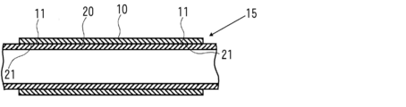
- Method A it is sectional drawing for description which shows the state in which the tube joining intermediate body which consists of a 1st tube and a 2nd tube was formed. It is sectional drawing for description which shows the state by which the part containing the joining area
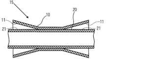
- FIG. It is sectional drawing for description which shows the state by which the joining area
- FIG. It is sectional drawing for description which shows the state by which the whole diameter of each of the 1st tube and the 2nd tube was expanded in the surface activation process of the method B.
- the joining method of the resin tubes of the present invention is a method of joining the first tube and the second tube each made of synthetic resin.
- the material of the 1st tube and the 2nd tube applied to the joining method of the resin tubes of this invention will not be specifically limited if it is a synthetic resin.
- Specific examples of the synthetic resin constituting the first tube and the second tube include a silicone resin and a fluorine-containing silicone resin.
- Each of the first tube and the second tube may be made of the same kind of material or different materials.
- the resin tube joining method of the present invention includes a surface activation step for activating each of a joining region of a first tube and a joining region of a second tube, a joining region of the first tube, and a second tube.
- a bonding step of bringing the bonding regions into close contact with each other.
- the first tube and the second tube are joined in the respective joining regions in a state in which the joining region of the first tube and the joining region of the second tube are brought into close contact with each other by the contact process.
- a joining process is performed.
- the resin tube joining method of the present invention is not particularly limited as long as it is a method having the surface activation step and the adhesion step described above, but the following method A, method B and method C are preferred. .
- the following method A, method B, and method C are examples in which the outer peripheral surface of the first tube has a joining region and the inner peripheral surface of the second tube has a joining region.
- each of the bonding region 11 of the first tube 10 and the bonding region 21 of the second tube 20 is irradiated with light including vacuum ultraviolet light, and the bonding of the first tube 10 is performed. It is preferable that any one of the plasma processing steps in which atmospheric pressure plasma is brought into contact with each of the region 11 and the bonding region 20 of the second tube 20.
- FIG. 3 is an explanatory view showing a configuration of an example of a light irradiation apparatus used in the ultraviolet irradiation treatment process.
- This light irradiation apparatus has a lamp house 30 in which an ultraviolet lamp 35 is disposed.
- the lamp house 30 is provided with an ultraviolet transmission window 31 that transmits ultraviolet rays from the ultraviolet lamp 35 and emits the ultraviolet rays to the outside.
- the ultraviolet transmission window 31 is made of, for example, synthetic quartz glass.
- a mask 40 having a light transmitting part 41 and a light shielding part 42 is disposed between the ultraviolet light transmitting window 31 and the tube bonding intermediate 15.
- the ultraviolet lamp 35 a lamp that emits light L including vacuum ultraviolet rays, that is, ultraviolet rays having a wavelength of 200 nm or less is used.
- the ultraviolet lamp 35 that emits such light include an excimer lamp such as a xenon excimer lamp having an emission line at a wavelength of 172 nm, a low-pressure mercury lamp having an emission line at a wavelength of 185 nm, and a deuterium lamp having an emission line in a wavelength range of 120 to 200 nm. Can be suitably used.
- the illuminance of the vacuum ultraviolet rays applied to the joining region 11 of the first tube 10 and the joining region 21 of the second tube 20 is, for example, 10 to 20 mW / cm 2 .
- region 21 of the 2nd tube 20 is according to the material which comprises the 1st tube 10 and the 2nd tube 20, and the illumination intensity of a vacuum ultraviolet ray. For example, it is 10 to 120 seconds.
- the first tube 10 and the second tube 15 are rotated while rotating the tube bonding intermediate 15 about the central axis C of each of the first tube 10 and the second tube 20.
- the joining regions 11 and 21 of the tube 20 are irradiated with light L from the ultraviolet lamp 35. Thereby, each joining area
- FIG. 4 is an explanatory diagram showing a configuration of an example of an atmospheric pressure plasma apparatus used in the plasma processing step.
- This atmospheric pressure plasma apparatus has a rectangular parallelepiped casing 50 made of, for example, aluminum.
- a plate-like electrode 53 that is electrically connected to a high-frequency power source 55 is disposed horizontally.
- a dielectric layer 54 is formed on the lower surface of the electrode 53.
- the casing 50 is grounded, the electrode 53 constitutes a high-voltage side electrode, and the casing 50 constitutes a ground-side electrode.
- a gas supply port 51 for supplying process gas into the casing 50 is provided on the upper surface of the casing 50.
- a plurality of nozzles 52 that discharge atmospheric pressure plasma generated in the casing 50 to the outside are formed on the lower surface of the casing 50.
- a mask 56 having a passage portion 57 through which atmospheric pressure plasma emitted from the nozzle 52 passes and a shielding portion 58 that shields atmospheric pressure plasma is disposed between the nozzle 50 and the tube bonding intermediate 15. Yes.
- the process gas G is supplied from the gas supply port 51 into the casing 50 under atmospheric pressure or a pressure in the vicinity thereof.
- a high frequency electric field is applied between the electrode 53 and the casing 50 via the dielectric layer 54 by the high frequency power supply 55 in this state, a dielectric barrier discharge is generated between the electrode 53 and the casing 50.
- the process gas G existing between the casing 50 and the dielectric layer 54 is ionized or excited to generate the atmospheric pressure plasma AP.
- the atmospheric pressure plasma AP is discharged to the outside from the nozzle 52 of the casing 50.
- the process gas G containing nitrogen gas, argon gas or the like as a main component and containing 0.01 to 5% by volume of oxygen gas.
- a mixed gas of nitrogen gas and clean dry air (CDA) can be used.
- the power supplied from the high-frequency power source has a frequency of 20 to 70 kHz and a voltage of 5 to 15 kVp-p. Further, the processing time by the plasma processing is, for example, 5 to 30 seconds.
- the first tube 10 and the second tube are rotated while rotating the tube bonding intermediate 15 about the central axis C of each of the first tube 10 and the second tube 20.
- the atmospheric pressure plasma PG from the atmospheric pressure plasma apparatus is brought into contact with each of the 20 junction regions 11 and 21. Thereby, each joining area
- the adhesion state between the bonding region 11 of the first tube 10 and the bonding region 21 of the second tube 20 is maintained for a preset time.
- the holding time of the bonded state of the bonding regions 11 and 21 is preferably 1 to 24 hours, and more preferably 3 to 12 hours. In this way, the bonding state of the bonding regions 11 and 21 is held for a preset time, so that the bonding region 11 of the first tube 10 and the bonding region 21 of the second tube 20 are reliably bonded. Can do.
- the 1st tube 10 and the 2nd tube 20 can be joined by closely_contact
- the portion including the joining regions 11 and 21 in close contact with each other in each of the first tube 10 and the second tube is pressurized in the thickness direction, or the first tube 10 and the second tube It is preferable to heat the portion including the bonded regions 11 and 21 in close contact with each other while pressing in the thickness direction.
- the pressurizing pressure is, for example, 0.1 to 1.0 MPa.
- the first tube 10 having an inner diameter smaller than the outer diameter of the second tube 20 the self-shrinking force generated when the folded portion of the first tube 10 is returned to the original state is used.
- a portion including the joining regions 11 and 21 of the first tube 10 and the second tube 20 may be pressurized.
- the difference between the inner diameter of the first tube and the outer diameter of the second tube is, for example, ⁇ 1.0 to ⁇ 2.0 mm (a value obtained by subtracting the outer diameter of the second tube from the inner diameter of the first tube). is there.
- the heating temperature is 100 to 200 ° C., for example.
- the treatment time by pressurization or heat pressurization is, for example, 100 to 300 seconds.
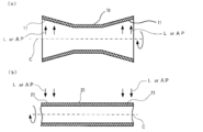
- Method B In the method B, as shown in FIG. 6A, the diameter of the portion including the joining region 11 in the first tube 10 is expanded by appropriate means, and the center of the first tube 10 is expanded. The joining region 11 is activated while rotating about the axis C as a rotation axis. On the other hand, as shown in FIG. 6B, the bonding region 21 is activated while rotating the second tube 20 with the central axis C as a rotation axis. In this way, the surface activation process is individually performed on each of the first tube 10 and the second tube 20.
- the surface activation process is preferably any one of the processes similar to the method A, that is, an ultraviolet irradiation process for irradiating light L including vacuum ultraviolet rays and a plasma treatment process for contacting atmospheric pressure plasma AP.
- Specific treatment conditions in the ultraviolet irradiation treatment step and the plasma treatment step are the same as those in Method A.
- the first tube 10 and the second tube 20 can be subjected to an ultraviolet irradiation process or a plasma process under different conditions.
- the joint region 11 of the first tube 10 and the joint region 21 of the second tube 20 are not in contact with each other while maintaining the expansion of the diameter of the first tube 10.
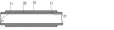
- the second tube 20 is inserted into the first tube 10 so as to face each other. Thereafter, the expansion of the diameter of the first tube 10 is released, thereby bringing the bonding region 11 of the first tube 10 and the bonding region 21 of the second tube 20 into close contact with each other as shown in FIG. In this manner, the adhesion process is performed on the joining region 11 of the first tube 10 and the joining region 21 of the second tube 20.
- the adhesion state between the joining region 11 of the first tube 10 and the joining region 21 of the second tube 20 may be maintained for a preset time. preferable.
- the first tube 10 and the second tube 20 in each of the first tube 10 and the second tube 20 are pressed in the thickness direction in a portion including the bonded regions 11 and 21, or the first tube 10 and the second tube 20. It is preferable to heat the portion including the bonding regions 11 and 21 in close contact with each other in the two tubes 20 while pressing in the thickness direction.
- the diameter of the entire first tube 10 may be expanded when the surface activation step is executed. Further, as shown in FIG. 10, the second tube 20 may be inserted into the first tube 10 in a state where the diameter of the entire first tube 10 is expanded when performing the contact process. .
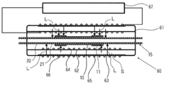
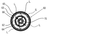
- a discharge vessel 61 having a double tube structure in which a discharge space S is formed between the inner tube 62 and the outer tube 63 is provided.
- An ultraviolet lamp 60 that radiates light including vacuum ultraviolet rays toward the inner side of the inner tube 62 is used.
- the discharge vessel 61 of the ultraviolet lamp 60 includes a straight tubular inner tube 62 made of a dielectric, and an inner tube disposed along the tube axis of the inner tube 62 so as to surround the inner tube 62.
- an outer tube 63 made of a dielectric material having an inner diameter larger than the outer diameter of the tube 62.
- Both end portions of the inner tube 62 and both end portions of the outer tube 63 are airtightly joined. Thereby, a cylindrical discharge space S is formed between the inner tube 62 and the outer tube 63.
- the discharge space S is filled with a discharge gas.
- the inner tube 62 in the discharge vessel 61 is provided with an inner electrode 64 in close contact with the inner peripheral surface thereof.
- the outer tube 63 in the discharge vessel 61 is provided with an outer electrode 65 in close contact with the outer peripheral surface thereof.
- the inner electrode 64 and the outer electrode 65 are each electrically connected to a high frequency power supply 67. Further, an ultraviolet reflection film 66 is formed on the inner peripheral surface of the outer tube 63.
- the inner electrode 64 can pass or transmit the vacuum ultraviolet rays from the discharge space S.
- a conductive wire made of aluminum is spirally wound along the inner peripheral surface of the inner tube 62, a net-like one, or an inner periphery of the inner tube 62. It is possible to use a film in which a film made of a conductive material is formed on a surface in accordance with a pattern having a mesh-like gap, a transparent electrode that transmits vacuum ultraviolet rays, or the like.
- the outer electrode 65 one having the same configuration as that of the inner electrode 64 can be used, and it is not necessary to be able to pass or transmit vacuum ultraviolet rays. it can.
- the ultraviolet reflecting film 66 include calcium pyrophosphate (Ca 2 P 2 O 7 ), calcium phosphate (Ca 3 (PO 4 ) 2 , magnesium pyrophosphate (Mg 2 P 2 O 7 ), and Ba—Na—Si—.
- a material containing any of O, SiO 2 , and Al 2 O 3 can be used, and these materials are preferably contained in a proportion exceeding 50 mass% with respect to the entire ultraviolet reflective film 66.
- the discharge gas for example, a rare gas such as xenon gas, argon gas, or krypton gas can be used.
- the first tube 10 and the second tube are joined using the ultraviolet lamp 60 as described below.
- a tube bonding intermediate 15 composed of the first tube 10 and the second tube 20 is produced. And the joining area
- FIG. Next, during the lighting of the ultraviolet lamp 60, the tube bonding intermediate 15 is passed through the inner tube 62 of the ultraviolet lamp 60. At this time, the joining regions 11 and 21 of the first tube 10 and the second tube 20 are in a state facing the inner peripheral surface of the inner tube 52.
- the light L from the ultraviolet lamp 60 is applied to the joint regions 11 and 21 of the first tube 10 and the second tube 20.
- region 11 and 21 of the 1st tube 10 and the 2nd tube 20 is activated.
- attachment process which adhere
- the first tube 10 and the second tube 20 are not rotated in the ultraviolet irradiation process step without rotating the tube bonding intermediate 15 (the first tube 10 and the second tube 20).
- the light L can be irradiated over the entire surface of each of the junction regions 11 and 21.
- the first tube 10 and the second tube are activated by activating each of the joining region 11 of the first tube 10 and the joining region 21 of the second tube 20.
- the material constituting the tube is modified. Therefore, even if the first tube 10 and the second tube 20 are made of different materials, a good joined state can be achieved. Accordingly, the degree of freedom in selecting the material of the first tube 10 and the second tube 20 is large, and the first tube 10 and the second tube 20 can be melted by heat or an adhesive can be used. Since it is unnecessary, problems such as hardening and shrinkage do not occur at the joined portion of the tube.
- Such a resin tube joining method is suitable as a method for joining a balloon portion tube and a catheter portion tube, for example, in the production of a balloon catheter.
- a resin sheet was prepared by cutting a resin tube for a balloon portion made of silicone resin (manufactured by Shin-Etsu Silicone) in the axial direction. This resin sheet is referred to as “resin sheet a”. A resin sheet for a balloon portion made of silicone resin (manufactured by Performance Materials) was cut in the axial direction to prepare a resin sheet. This resin sheet is referred to as “resin sheet b”. A resin sheet for the catheter part made of silicone resin (manufactured by Wacker Silicones) was cut in the axial direction to prepare a resin sheet. This resin sheet is referred to as “resin sheet c”.
- Condition setting of the surface activation process Each of the resin sheet a, the resin sheet b, and the resin sheet c is fixed on the stage in a flattened state. Light was irradiated by the light irradiation apparatus shown in FIG. 3 (however, a mask is not disposed).
- a xenon excimer lamp that irradiates vacuum ultraviolet light having a center wavelength of 172 nm is used as the ultraviolet lamp, and a glass made of synthetic quartz glass is used as the ultraviolet transmission window.
- the conditions of light irradiation are as follows. Distance from UV transmitting window to resin sheet: 3mm Illuminance on the outer surface of the ultraviolet irradiation window: 40 mW / cm 2 Atmosphere around resin sheet: Air
- the light irradiation time was changed stepwise, the contact angle with pure water on the light irradiation surface of the resin sheet was measured, and the light irradiation time until the change in the contact angle was stabilized was obtained.
- the light irradiation time of the resin sheet a was 60 seconds
- the light irradiation time of the resin sheet b was 75 seconds
- the light irradiation time of the resin sheet c was 45 seconds.
- Casing (50) material Aluminum Electrode (53) material: Super Invar (with 500 ⁇ m alumina coating formed on the surface by thermal spraying)) Dimension of surface of electrode (53): 50mm x 300mm Distance between casing (53) and dielectric layer (54): 0.5 mm Voltage: 7.0kVp-p, Frequency: 60kHz, Rated power: 1100VA
- Process gas Mixed gas of nitrogen gas (flow rate 150 L / min) and clean dry air (flow rate 1 l / min) (oxygen concentration in the process gas is about 0.14 vol%)
- the treatment time was changed stepwise, the contact angle of pure water on the contact surface with the atmospheric pressure plasma in the resin sheet was measured, and the treatment time until the change of the contact angle became stable was obtained.
- the processing time of the resin sheet a was 5 seconds
- the processing time of the resin sheet b was 10 seconds
- the processing time of the resin sheet c was 5 seconds.
- Adhesion process condition setting (Test 1-1) About the resin sheet a and the resin sheet c, light was irradiated similarly to the condition setting of said ultraviolet irradiation process process. The light irradiation time for the resin sheet a was 60 seconds, and the light irradiation time for the resin sheet c was 45 seconds. Next, the resin sheet a and the resin sheet c were brought into close contact with each other so that the respective light irradiation surfaces were in contact with each other, and were pressed with a press machine under conditions of a pressurization pressure of 0.35 MPa and a pressurization time of 150 seconds.
- Evaluation method of bonding state About the joined body consisting of the resin sheet a and the resin sheet c, a tensile shear test was performed in accordance with JIS K6850. Then, when a 0.2 MPa tensile shear force was applied to the bonded body for 10 minutes, the bonded state was evaluated based on whether or not the both resin sheets were peeled off. Specifically, the case where peeling of both resin sheets did not occur in the above test was evaluated as good bonding state ( ⁇ ), and the case where peeling of both resin sheets occurred was evaluated as poor bonding state (x).
- Test 1-2 Resin sheet a and resin sheet a and resin sheet were tested in the same manner as in Test 1-1, except that the resin sheet a and resin sheet c were not held in close contact after the pressure on the resin sheet a and the resin sheet c was released. The joining state with the sheet c was evaluated.
- Test 1-3 The resin sheet a and the resin sheet c were irradiated with light under the same conditions as in Test 1-1. Next, the resin sheet a and the resin sheet c are brought into close contact with each other so that the respective light irradiation surfaces are in contact with each other, and the press pressure is 0.35 MPa, the press time is 150 seconds, and the heating temperature is 100 ° C. After that, the pressure on the resin sheet a and the resin sheet c was released. Then, in the same manner as in Test 1-1, the bonding state between the resin sheet a and the resin sheet c immediately after releasing the pressure was evaluated. The results are shown in Table 1.
- Test 1-4 Except that the light irradiation time for the resin sheet a was changed to 45 seconds, the bonding state between the resin sheet a and the resin sheet c immediately after releasing the pressure was evaluated in the same manner as in Test 1-3. The results are shown in Table 1.
- the resin sheet a and the resin sheet c are brought into close contact with each other to be treated, and are pressed by a press machine under conditions of a pressing pressure of 0.35 MPa and a pressing time of 150 seconds, The pressure applied to the resin sheet a and the resin sheet c was released. Then, in the same manner as in Test 1-1, the bonding state between the resin sheet a and the resin sheet c immediately after releasing the pressure was evaluated. The results are shown in Table 1.
- Test 2-1 The bonding state between the resin sheet b and the resin sheet c was evaluated in the same manner as in Test 1-1 except that the resin sheet b was used instead of the resin sheet a and the light irradiation time for the resin sheet b was 75 seconds. .
- the results are shown in Table 2.
- Test 2-2 The resin sheet b and the resin sheet c were irradiated with light under the same conditions as in Test 2-1. Next, the resin sheet b and the resin sheet c are brought into close contact with each other so that the respective light irradiation surfaces are in contact with each other, and the pressing pressure is 0.35 MPa, the pressing time is 150 seconds, and the heating temperature is 100 ° C. After that, the pressure applied to the resin sheet b and the resin sheet c was released. Then, in the same manner as in Test 1-1, the bonding state between the resin sheet b and the resin sheet c immediately after releasing the pressure was evaluated. The results are shown in Table 2.
- Test 2-3 Except that the light irradiation time for the resin sheet b was changed to 45 seconds, the bonding state between the resin sheet b and the resin sheet c immediately after releasing the pressure was evaluated in the same manner as in Test 2-2. The results are shown in Table 2.
- Test 2-5 Except that the light irradiation time for each of the resin sheet b and the resin sheet c was changed to 30 seconds, the bonding state between the resin sheet b and the resin sheet c immediately after releasing the pressure was performed in the same manner as in Test 2-4. evaluated. The results are shown in Table 2.
- Test 2-6 Except that the light irradiation time for each of the resin sheet b and the resin sheet c was changed to 20 seconds, the bonding state between the resin sheet b and the resin sheet c immediately after releasing the pressure was performed in the same manner as in Test 2-4. evaluated. The results are shown in Table 2.
- Test 2--7 Except that the light irradiation time for each of the resin sheet b and the resin sheet c was changed to 10 seconds, the bonding state between the resin sheet b and the resin sheet c immediately after releasing the pressure was the same as in Test 2-4. evaluated. The results are shown in Table 2.
- the resin sheet b and the resin sheet c were arranged at a position where the distance from the nozzle of the atmospheric pressure plasma apparatus to the surface to be processed was 3 mm. Then, while supplying nitrogen gas having a flow rate of 150 L / min and clean dry air having a flow rate of 1 L / min as the process gas (the oxygen concentration in the plasma gas is about 0.14 vol%), the atmospheric pressure plasma apparatus is operated. Thus, the plasma treatment was performed for 10 seconds for the resin sheet b and for 5 seconds for the resin sheet c. Next, the resin sheet b and the resin sheet c are brought into close contact with each other to be treated, and the pressing pressure is 0.35 MPa, the pressing time is 150 seconds, and the heating temperature is 100 ° C.
- the results of Test 1-2 show that when the resin sheet a and the resin sheet c each made of a silicone resin are to be joined, heating is good without heating. It is understood that a bonded state is obtained. Also, from the results of Test 2-1, when joining the resin sheet b made of silicone resin and the resin sheet c made of silicone resin, heating is performed by maintaining the contact state for 24 hours after releasing the pressure. It is understood that a good bonding state can be obtained without any problems. The reason is not clear, but is estimated as follows.
- the reaction for bonding on the close contact surface has a relatively long reaction life, and when the surfaces activated by ultraviolet irradiation in the resin material are in close contact with each other, the reaction continues and finally close contact Bonding proceeds over the entire surface. Therefore, even if the bonding is not sufficiently advanced immediately after the pressure is released, it is considered that the bonding proceeds over the entire adhesion surface by maintaining the adhesion state for 24 hours. On the other hand, if the materials are relatively susceptible to reaction at the close contact surface, even if the reaction region is unevenly distributed, the reaction region becomes relatively wide, and the two can be joined in a short time. It seems that it will progress sufficiently.
- the respective light irradiation times were 10 seconds or more, and the pressurizing pressure was 0 in the pressurization of the resin sheet b and the resin sheet c.
- the heating temperature is 100 ° C. at 122 MPa or higher, it is understood that a good bonding state can be obtained immediately after the pressure is released.
- the treatment time of each atmospheric pressure plasma is 5 seconds or more.
- the pressurization of the resin sheet b and the resin sheet c it is understood that if the pressurization pressure is 0.35 MPa or more, a good bonded state can be obtained immediately after the pressurization is released.
- the treatment time of the resin sheet b by atmospheric pressure plasma is 10 seconds or more, and the treatment time of the resin sheet c by atmospheric pressure plasma is 5 If the pressurization pressure is 0.35 MPa or more and the heating temperature is 100 ° C. in the pressurization of the resin sheet b and the resin sheet c in a second or more, a good bonding state can be obtained immediately after the pressurization is released. Is understood.
- the following resin tubes were prepared as the first tube and the second tube.
- the first tube is for a balloon portion made of silicone resin (manufactured by Performance Materials), the outer diameter is 5.6 mm, the inner diameter is 5.3 mm, the total length is 40 mm, and the wall thickness is 0.15 mm.
- the second tube is for a catheter portion made of silicone resin (manufactured by Wacker Silicones), and has an outer diameter of 7.3 mm, an inner diameter of 4.3 mm, and a wall thickness of 1.5 mm.
- the first tube has a joining region extending in the circumferential direction on the inner circumferential surface of both end portions thereof, and the second tube is circumferentially positioned at a position corresponding to the connection region of the first tube on the outer circumferential surface.
- a bonding region extending to The axial width in the joining region of each of the first tube and the second tube is 10 mm.
- the tube joining intermediate body was produced by inserting the 2nd tube in the 1st tube so that each joined field may overlap. Then, the joining area
- the ultraviolet irradiation process process was performed.
- a xenon excimer lamp that irradiates vacuum ultraviolet light having a center wavelength of 172 nm is used as the ultraviolet lamp, and a glass made of synthetic quartz glass is used as the ultraviolet transmission window.
- the conditions of light irradiation are as follows. Distance from UV transmitting window to tube junction intermediate: 3mm Illuminance on the outer surface of the ultraviolet irradiation window: 40 mW / cm 2 Light irradiation time: 20 seconds Atmosphere around tube junction intermediate: Air
- the first tube is expanded by injecting air into the gap between the first tube and the second tube in the obtained tube bonded body through a previously formed air injection port. To form a balloon.
- a good joined state was achieved without air leakage.
- a bubble etc. do not exist between the joining area
- Example 2 The following resin tubes were used as the first tube and the second tube, and the same procedure as in Example 1 was performed except that the pressurizing jig was not applied to the portion including the joining region in the adhesion process. Then, the first tube and the second tube were joined.
- the first tube is for a balloon part made of silicone resin (manufactured by Performance Materials), and has an outer diameter of 6.7 mm, an inner diameter of 6.5 mm, an overall length of 40 mm, and a wall thickness of 0.1 mm.
- the second tube is for a catheter portion made of silicone resin (manufactured by Wacker Silicones), and has an outer diameter of 8 mm, an inner diameter of 5.0 mm, and a wall thickness of 1.5 mm.
- the first tube has a joining region extending in the circumferential direction on the inner circumferential surface of both end portions thereof, and the second tube is circumferentially positioned at a position corresponding to the connection region of the first tube on the outer circumferential surface.
- a bonding region extending to The axial width in the joining region of each of the first tube and the second tube is 10 mm.
- the first tube is inflated to form a balloon by injecting air into the gap between the first tube and the second tube in the obtained tube assembly through a previously formed air inlet. did.
- a good joined state was achieved without air leakage.
- a bubble etc. do not exist between the joining area
- Example 3 The following resin tubes were used as the first tube and the second tube, and the same procedure as in Example 1 was performed except that the pressurizing jig was not applied to the portion including the joining region in the adhesion process. Then, the first tube and the second tube were joined.
- the first tube is for a balloon portion made of silicone resin (manufactured by Performance Performance Materials), and has an outer diameter of 7.3 mm, an inner diameter of 7.0 mm, and a wall thickness of 0.15 mm.
- the second tube is for a catheter portion made of silicone resin (manufactured by Wacker Silicones), and has an outer diameter of 8 mm, an inner diameter of 5.0 mm, and a wall thickness of 0.15 mm.
- the first tube has a joining region extending in the circumferential direction on the inner circumferential surface of both end portions thereof, and the second tube is circumferentially positioned at a position corresponding to the connection region of the first tube on the outer circumferential surface.
- a bonding region extending to The axial width in the joining region of each of the first tube and the second tube is 10 mm.
- the first tube is inflated to form a balloon by injecting air into the gap between the first tube and the second tube in the obtained tube assembly through a previously formed air inlet. did.
- a good joined state was achieved without air leakage.
- a bubble exists slightly between the joining area
Landscapes
- Engineering & Computer Science (AREA)
- Mechanical Engineering (AREA)
- Health & Medical Sciences (AREA)
- Physics & Mathematics (AREA)
- Toxicology (AREA)
- Electromagnetism (AREA)
- Plasma & Fusion (AREA)
- Life Sciences & Earth Sciences (AREA)
- Thermal Sciences (AREA)
- Heart & Thoracic Surgery (AREA)
- Biophysics (AREA)
- Pulmonology (AREA)
- Anesthesiology (AREA)
- Biomedical Technology (AREA)
- Hematology (AREA)
- Animal Behavior & Ethology (AREA)
- General Health & Medical Sciences (AREA)
- Public Health (AREA)
- Veterinary Medicine (AREA)
- Child & Adolescent Psychology (AREA)
- Lining Or Joining Of Plastics Or The Like (AREA)
- Treatments Of Macromolecular Shaped Articles (AREA)
Abstract
Description
例えば、特許文献1には、2つの樹脂製チューブの開口端部同士を熱融着により連結させる樹脂製チューブの接合方法が開示されている。また、特許文献2には、バルーンカテーテルの製造において、バルーン部用の樹脂製チューブとカテーテル部用の樹脂製チューブと接合する方法として、熱融着による方法や、紫外線硬化性接着剤を用いて接合する方法が開示されている。
熱融着による接合方法においては、一方のチューブを構成する樹脂と他方のチューブを構成する樹脂が、互いに相溶性が良好なものに限定される。そのため、一般に、熱融着による接合方法は、一方のチューブの材質と他方のチューブの材質とが互いに相違するときには採用されにくく、材料選択の自由度が小さい、という問題がある。
また、一方のチューブを構成する樹脂と他方のチューブを構成する樹脂が、互いに相溶性が良好なものであっても、それぞれのチューブの表面部分を十分に熱溶融することが必要であるため、形成される接合部分が硬くなり、得られるチューブ接合体のフレキシブル性が損なわれる、という問題がある。
また、紫外線硬化性接着剤は、硬化時に収縮を伴うことがあるため、得られるチューブ接合体が変形する、という問題がある。
特に、バルーンカテーテルの製造においては、極めて高レベルの接着力・信頼性が要求されるので、接着力が高い接着剤が選定されるが、このような接着剤は一般に粘度が高いため、チューブ同士を接合する際の作業性が低い、という問題がある。
前記第1のチューブの接合領域および前記第2のチューブの接合領域の各々を活性化する表面活性化工程と、
それぞれ前記表面活性化工程を経由した前記第1のチューブの接合領域および前記第2のチューブの接合領域を互いに密着させる密着工程と
を有することを特徴とする。
また、前記表面活性化工程は、前記第1のチューブの接合領域および前記第2のチューブの接合領域の各々に、大気圧プラズマを接触させるプラズマ処理工程であることが好ましい。
内側管および外側管の間に放電空間が形成された二重管構造の放電容器を有し、当該内側管の内側方向に真空紫外線を含む光を放射するランプを用い、前記ランプの点灯中において、当該ランプの内側管の内に、前記第1のチューブおよび前記第2のチューブの各々を、それぞれ接合領域が前記内側管に向いた状態で通過させることにより、第1のチューブおよび前記第2のチューブの各々の接合領域に光を照射して各接合領域を活性化する表面活性化工程と、
それぞれ前記表面活性化工程を経由した前記第1のチューブの接合領域および前記第2のチューブの接合領域を互いに密着させる密着工程と
を有することを特徴とする。
前記表面活性化工程において、第1のチューブおよび第2のチューブの接合領域を活性化する前に、前記第1のチューブ内に前記第2のチューブを、それぞれの接合領域が重なるよう挿入し、その後、前記第1のチューブにおける接合領域を含む部分を折り返すことにより、前記第1のチューブの接合領域および前記第2のチューブの接合領域を露出させ、この状態で、前記第1のチューブの接合領域および前記第2のチューブの接合領域を活性化し、
その後、前記第1のチューブにおける折り返し部分を元に戻すことにより、前記密着工程を実行することが好ましい。
前記第1のチューブおよび前記第2のチューブの各々に対して、前記表面活性化工程を実行し、
前記密着工程において、前記第1のチューブの接合領域と前記第2のチューブの接合領域とが互いに接触せずに対向するよう、前記第1のチューブ内に前記第2のチューブを挿入し、その後、前記第1のチューブの接合領域と前記第2のチューブの接合領域と密着することが好ましい。
また、前記密着工程において、前記第1のチューブの接合領域と前記第2のチューブの接合領域との密着状態が、予め設定された時間保持されることが好ましい。
また、前記密着工程において、前記第1のチューブおよび前記第2のチューブの各々における互いに密着した接合領域を含む部分を厚み方向に加圧することが好ましい。
また、前記密着工程において、前記第1のチューブおよび前記第2のチューブの各々における互いに密着した接合領域を含む部分を厚み方向に加圧しながら加熱することが好ましい。
本発明の樹脂製チューブの接合方法は、それぞれ合成樹脂らかなる第1のチューブおよび第2のチューブを接合する方法である。本発明の樹脂製チューブの接合方法に適用される第1のチューブおよび第2のチューブの材質は、合成樹脂であれば特に限定されるものではない。第1のチューブおよび第2のチューブを構成する合成樹脂の具体例としては、シリコーン樹脂、フッ素含有シリコーン樹脂などが挙げられる。
また、第1のチューブおよび第2のチューブの各々は、互いに同種の材料よりなるものであっても異なる材料よりなるものであってもよい。
本発明の樹脂製チューブの接合方法は、上記の表面活性化工程および密着工程を有する方法であれば、その他具体的な方法は特に限定されないが、下記の方法A、方法Bおよび方法Cが好ましい。下記の方法A、方法Bおよび方法Cは、第1のチューブの外周面に接合領域を有し、第2のチューブの内周面に接合領域を有する場合の例である。
方法Aにおいては、表面活性化工程において、図1に示すように、第1のチューブ10および第2のチューブ20の接合領域11,21を活性化する前に、第1のチューブ10の管内に第2のチューブ20を、それぞれの接合領域11,21が重なるよう挿入することにより、チューブ接合中間体15を作製する。その後、図2に示すように、チューブ接合中間体15の第1のチューブ10における接合領域11を含む部分を折り返すことにより、第1のチューブ10の接合領域11および第2のチューブ20の接合領域21を露出させる。そして、チューブ接合中間体15を、第1のチューブ10および第2のチューブ20の各々の中心軸Cを回転軸として回転させながら、第1のチューブ10および第2のチューブ20の各々の接合領域11,21を活性化する。このように、方法Aにおいては、第1のチューブ10の接合領域11および第2のチューブ20の接合領域21の各々の活性化を同時に行うことができる。図2において、矢印は真空紫外線を含む光Lまたは大気圧プラズマAPを示す。
表面活性化工程は、第1のチューブ10の接合領域11および第2のチューブ20の接合領域21の各々に、真空紫外線を含む光を照射する紫外線照射処理工程、並びに第1のチューブ10の接合領域11および第2のチューブ20の接合領域20の各々に、大気圧プラズマを接触させるプラズマ処理工程のいずれかであることが好ましい。
図3は、紫外線照射処理工程に用いられる光照射装置の一例における構成を示す説明図である。この光照射装置は、内部に紫外線ランプ35が配置されたランプハウス30を有する。このランプハウス30には、紫外線ランプ35からの紫外線を透過して外部に出射する紫外線透過窓31が設けられている。この紫外線透過窓31は、例えば合成石英ガラスにより構成されている。紫外線透過窓31とチューブ接合中間体15との間には、透光部41および遮光部42を有するマスク40が配置されている。
このような光を放射する紫外線ランプ35としては、波長172nmに輝線を有するキセノンエキシマランプ等のエキシマランプ、波長185nmに輝線を有する低圧水銀ランプ、波長120~200nmの範囲に輝線を有する重水素ランプを好適に用いることができる。
第1のチューブ10の接合領域11および第2のチューブ20の接合領域21に対する光Lの照射時間は、第1のチューブ10および第2のチューブ20を構成する材料や、真空紫外線の照度に応じて適宜設定されるが、例えば10~120秒間である。
図4は、プラズマ処理工程に用いられる大気圧プラズマ装置の一例における構成を示す説明図である。この大気圧プラズマ装置は、例えばアルミニウムからなる直方体状のケーシング50を有する。このケーシング50内には、高周波電源55に電気的に接続された板状の電極53が水平に配置されている。この電極53の下面には、誘電体層54が形成されている。この例の大気圧プラズマ装置においては、ケーシング50が接地されており、電極53によって高圧側電極が構成され、ケーシング50によって接地側電極が構成されている。
ケーシング50の上面には、ケーシング50内にプロセスガスを供給するガス供給口51が設けられている。また、ケーシング50の下面には、ケーシング50内において発生した大気圧プラズマを外部に放出する複数のノズル52が形成されている。
また、ノズル50とチューブ接合中間体15との間には、ノズル52から放出された大気圧プラズマが通過する通過部57および大気圧プラズマが遮蔽される遮蔽部58を有するマスク56が配置されている。
また、高周波電源から供給される電力は、周波数が20~70kHz、電圧が5~15kVp-pである。
また、プラズマ処理による処理時間は、例えば5~30秒間である。
このようにして、表面活性化工程を実行した後、図5に示すように、第1のチューブ10における折り返し部分を元の状態に戻す。これにより、第1のチューブ10の接合領域11および第2のチューブ20の接合領域21を互いに密着させる密着工程を実行する。
このように、接合領域11,21の密着状態が、予め設定された時間保持されることにより、第1のチューブ10の接合領域11と第2のチューブ20の接合領域21と確実に接合することができる。
第1のチューブ10として、その内径が第2のチューブ20の外径より小さいものを用いることにより、第1のチューブ10において折り返し部分を元の状態に戻したときに生ずる自己収縮力によって、第1のチューブ10および第2のチューブ20の接合領域11,21を含む部分を加圧してもよい。第1のチューブの内径と第2のチューブの外径との差は、例えば-1.0~-2.0mm(第1のチューブの内径から第2のチューブの外径を減じた値)である。
また、接合領域11,21を含む部分を加熱する場合においては、加熱温度は、例えば100~200℃である。
また、加圧または加熱加圧による処理時間は、例えば100~300秒間である。
方法Bにおいては、図6(a)に示すように、適宜の手段によって、第1のチューブ10における接合領域11を含む部分の径を拡張させ、当該第1のチューブ10に対して、その中心軸Cを回転軸として回転させながら、接合領域11の活性化を行う。一方、図6(b)に示すように、第2のチューブ20に対して、その中心軸Cを回転軸として回転させながら、接合領域21の活性化を行う。このようにして、第1のチューブ10および第2のチューブ20の各々に対して、個別に表面活性化工程を実行する。
以上において、表面活性化工程は、方法Aと同様の工程、すなわち真空紫外線を含む光Lを照射する紫外線照射処理工程および大気圧プラズマAPを接触させるプラズマ処理工程のいずれかであることが好ましい。
紫外線照射処理工程およびプラズマ処理工程における具体的な処理条件は、方法Aと同様である。また、方法Bにおいては、第1のチューブ10および第2のチューブ20に対して、互いに異なる条件で紫外線照射処理工程またはプラズマ処理工程を行うことができる。
方法Bの密着工程においては、方法Aと同様にして、第1のチューブ10の接合領域11と第2のチューブ20の接合領域21との密着状態が、予め設定された時間保持されることが好ましい。
また、方法Aと同様にして、第1のチューブ10および第2のチューブ20の各々における互いに密着した接合領域11,21を含む部分を厚み方向に加圧する、或いは、第1のチューブ10および第2のチューブ20の各々における互いに密着した接合領域11,21を含む部分を厚み方向に加圧しながら加熱することが好ましい。
方法Cにおいては、表面活性化工程において、図11および図12に示すように、内側管62および外側管63の間に放電空間Sが形成された二重管構造の放電容器61を有し、内側管62の内側方向に真空紫外線を含む光を放射する紫外線ランプ60が用いられる。
具体的に説明すると、この紫外線ランプ60の放電容器61は、誘電体よりなる直管状の内側管62と、この内側管62の管軸に沿って当該内側管62を取り囲むよう配置された、内側管62の外径より大きい内径を有する誘電体よりなる外側管63とを有する。内側管62の両端部と外側管63の両端部とは気密に接合されている。これにより、内側管62と外側管63との間に円筒状の放電空間Sが形成されている。この放電空間Sには、放電用ガスが封入されている。
放電容器61における内側管62には、その内周面に密接して内側電極64が設けられている。一方、放電容器61における外側管63には、その外周面に密接して外側電極65が設けられている。内側電極64および外側電極65は、それぞれ高周波電源67に電気的に接続されている。また、外側管63の内周面には、紫外線反射膜66が形成されている。
内側電極64は、放電空間Sからの真空紫外線を通過若しくは透過し得るものである。このような内側電極64としては、例えば、アルミニウムよりなる導電性素線が内側管62の内周面に沿って螺旋状に巻回された構造のもの、網状のもの、内側管62の内周面に導電性材料からなる膜が網目状などの隙間を有するパターンに従って形成されてなるもの、真空紫外線を透過する透明電極などを用いることができる。
外側電極65としては、内側電極64と同様の構成のものを用いることができ、真空紫外線を通過若しくは透過し得るものであることが不要なため、不透光性の帯状のものも用いることができる。
紫外線反射膜66としては、例えば、ピロリン酸カルシウム(Ca2 P2 O7 )、リン酸カルシウム(Ca3 (PO4 )2 、ピロリン酸マグネシウム(Mg2 P2 O7 )、および、Ba-Na-Si-O、SiO2 、Al2 O3 のいずれかを含む材料を用いることができる。これらの材料は、紫外線反射膜66全体に対して50質量%を超える割合で含有されていることが好ましい。
放電用ガスとしては、例えば、キセノンガス、アルゴンガス、クリプトンガスなどの希ガスを用いることができる。
先ず、方法Aと同様にして、第1のチューブ10および第2のチューブ20よりなるチューブ接合中間体15を作製する。そして、第1のチューブ10における接合領域11を含む部分を折り返すことにより、第1のチューブ10の接合領域11および第2のチューブ20の接合領域21を露出させる。次いで、紫外線ランプ60の点灯中において、紫外線ランプ60の内側管62内に、チューブ接合中間体15を通過させる。このとき、第1のチューブ10および第2のチューブ20の各々の接合領域11,21は、内側管52の内周面に向いた状態である。その結果、第1のチューブ10および第2のチューブ20の各々の接合領域11,21には、紫外線ランプ60からの光Lが照射される。これにより、第1のチューブ10および第2のチューブ20の各々の接合領域11,21が活性化される。その後、方法Aと同様にして第1のチューブ10の接合領域11および第2のチューブ20の接合領域21を互いに密着させる密着工程を実行する。
このような方法によれば、紫外線照射処理工程において、チューブ接合中間体15(第1のチューブ10および第2のチューブ20)を回転させることなしに、第1のチューブ10および第2のチューブ20の各々の接合領域11,21の全面にわたって、光Lを照射することができる。
このような樹脂製チューブの接合方法は、例えばバルーンカテーテルの製造において、バルーン部用チューブとカテーテル部用チューブとを接合するための方法として好適である。
1.試験用試料の作製
シリコーン樹脂(信越シリコーン社製)よりなるバルーン部用の樹脂製チューブを軸方向に切断することにより、樹脂シートを作製した。この樹脂シートを「樹脂シートa」とする。
シリコーン樹脂(Momentive Performance Materials社製)よりなるバルーン部用の樹脂製チューブを軸方向に切断することにより、樹脂シートを作製した。この樹脂シートを「樹脂シートb」とする。
シリコーン樹脂(Wacker Silicones社製)よりなるカテーテル部用の樹脂製チューブを軸方向に切断することにより、樹脂シートを作製した。この樹脂シートを「樹脂シートc」とする。
(1)紫外線照射処理工程の条件設定
樹脂シートa、樹脂シートbおよび樹脂シートcの各々を平坦化させた状態でステージ上に固定し、当該樹脂シートに対して、図3に示す光照射装置(但し、マスクを配置していないもの。)によって光を照射した。
以上において、紫外線ランプとしては、中心波長172nmの真空紫外光を照射するキセノンエキシマランプを使用し、紫外線透過窓としては、合成石英ガラスよりなるものを使用した。また、光照射の条件は下記の通りである。
紫外線透過窓から樹脂シートまでの距離:3mm
紫外線照射窓の外表面における照度:40mW/cm2
樹脂シートの周囲の雰囲気:大気
樹脂シートa、樹脂シートbおよび樹脂シートcの各々を平坦化させた状態でステージ上に固定し、当該樹脂シートに対して、図4に示す大気圧プラズマ装置(但し、マスクを配置していないもの。)によって大気圧プラズマを接触させた。
以上において、大気圧プラズマ装置の仕様および使用したプロセスガスは下記の通りである。
ケーシング(50)の材質:アルミニウム
電極(53)の材質:スーパーインバー(溶射によって表面に500μmのアルミナよりなる被膜が形成されてなるもの))
電極(53)の表面の寸法:50mm×300mm
ケーシング(53)と誘電体層(54)との離間距離:0.5mm
電圧:7.0kVp-p 、周波数:60k Hz、定格電力:1100VA
プロセスガス:窒素ガス(流量150L/min)およびクリーンドライエア(流量1l/min)の混合ガス(プロセスガス中の酸素濃度が約0.14体積%)
(試験1-1)
樹脂シートaおよび樹脂シートcについて、上記の紫外線照射処理工程の条件設定と同様にして光を照射した。樹脂シートaに対する光照射時間を60秒間、樹脂シートcに対する光照射時間を45秒間とした。
次いで、樹脂シートaと樹脂シートcとを、それぞれの光照射面が対接するよう密着させ、プレス機によって、加圧圧力が0.35MPa、加圧時間が150秒間の条件で加圧した。その後、樹脂シートaおよび樹脂シートcに対する加圧を解除し、樹脂シートaと樹脂シートcとの密着状態を24時間保持した。そして、樹脂シートaと樹脂シートcとの接合状態を、下記のようにして評価した。結果を表1に示す。
樹脂シートaおよび樹脂シートcからなる接合体について、JIS K6850に準拠して引張せん断試験を行った。そして、上記接合体に0.2MPaの引張せん断力を10分間作用させたときに、両樹脂シートの剥離が発生したか否かにより接合状態を評価した。
具体的には、上記試験により両樹脂シートの剥離が発生しなかった場合を、接合状態良好(○)とし、両樹脂シートの剥離が発生した場合を接合状態不良(×)として評価した。
樹脂シートaおよび樹脂シートcに対する加圧を解除した後において、樹脂シートaと樹脂シートcとの密着状態の保持を行わなかったこと以外は試験1-1と同様にして、樹脂シートaと樹脂シートcとの接合状態を評価した。
樹脂シートaおよび樹脂シートcについて、試験1-1と同様の条件で光を照射した。 次いで、樹脂シートaと樹脂シートcとを、それぞれの光照射面が対接するよう密着させ、プレス機によって、加圧圧力が0.35MPa、加圧時間が150秒間、加熱温度が100℃の条件で加圧し、その後、樹脂シートaおよび樹脂シートcに対する加圧を解除した。そして、試験1-1と同様にして、加圧を解除した直後における樹脂シートaと樹脂シートcとの接合状態を評価した。結果を表1に示す。
樹脂シートaに対する光照射時間を45秒間に変更したこと以外は試験1-3と同様にして、加圧を解除した直後における樹脂シートaと樹脂シートcとの接合状態を評価した。結果を表1に示す。
樹脂シートaおよび樹脂シートcに対する加圧において、加圧圧力を0.122MPaに変更したこと以外は試験1-4と同様にして、加圧を解除した直後における樹脂シートaと樹脂シートcとの接合状態を評価した。結果を表1に示す。
大気圧プラズマ装置のノズルから被処理面までの距離が3mmとなる位置に、樹脂シートaおよび樹脂シートcを配置した。そして、プロセスガスとして、流量が150L/minの窒素ガスおよび流量が1L/minのクリーンドライエアを供給しながら(プラズマ用ガス中の酸素濃度が約0.14体積%)、大気圧プラズマ装置を作動させことにより、樹脂シートaおよび樹脂シートcに対してそれぞれ5秒間のプラズマ処理を行った。次いで、樹脂シートaと樹脂シートcとを、それぞれの被処理面が対接するよう密着させ、プレス機によって、加圧圧力が0.35MPa、加圧時間が150秒間の条件で加圧し、その後、樹脂シートaおよび樹脂シートcに対する加圧を解除した。そして、試験1-1と同様にして、加圧を解除した直後における樹脂シートaと樹脂シートcとの接合状態を評価した。結果を表1に示す。
樹脂シートaの代わりに樹脂シートbを用い、樹脂シートbに対する光照射時間を75秒間としたこと以外は試験1-1と同様にして、樹脂シートbと樹脂シートcとの接合状態を評価した。結果を表2に示す。
樹脂シートbおよび樹脂シートcについて、試験2-1と同様の条件で光を照射した。 次いで、樹脂シートbと樹脂シートcとを、それぞれの光照射面が対接するよう密着させ、プレス機によって、加圧圧力が0.35MPa、加圧時間が150秒間、加熱温度が100℃の条件で加圧し、その後、樹脂シートbおよび樹脂シートcに対する加圧を解除した。そして、試験1-1と同様にして、加圧を解除した直後における樹脂シートbと樹脂シートcとの接合状態を評価した。結果を表2に示す。
樹脂シートbに対する光照射時間を45秒間に変更したこと以外は試験2-2と同様にして、加圧を解除した直後における樹脂シートbと樹脂シートcとの接合状態を評価した。結果を表2に示す。
樹脂シートbおよび樹脂シートcに対する加圧において、加圧圧力を0.122MPaに変更したこと以外は試験2-3と同様にして、加圧を解除した直後における樹脂シートbと樹脂シートcとの接合状態を評価した。結果を表2に示す。
樹脂シートbおよび樹脂シートcの各々に対する光照射時間を30秒間に変更したこと以外は試験2-4と同様にして、加圧を解除した直後における樹脂シートbと樹脂シートcとの接合状態を評価した。結果を表2に示す。
樹脂シートbおよび樹脂シートcの各々に対する光照射時間を20秒間に変更したこと以外は試験2-4と同様にして、加圧を解除した直後における樹脂シートbと樹脂シートcとの接合状態を評価した。結果を表2に示す。
樹脂シートbおよび樹脂シートcの各々に対する光照射時間を10秒間に変更したこと以外は試験2-4と同様にして、加圧を解除した直後における樹脂シートbと樹脂シートcとの接合状態を評価した。結果を表2に示す。
大気圧プラズマ装置のノズルから被処理面までの距離が3mmとなる位置に、樹脂シートbおよび樹脂シートcを配置した。そして、プロセスガスとして、流量が150L/minの窒素ガスおよび流量が1L/minのクリーンドライエアを供給しながら(プラズマ用ガス中の酸素濃度が約0.14体積%)、大気圧プラズマ装置を作動させことにより、樹脂シートbに対しては10秒間、樹脂シートcに対しては5秒間のプラズマ処理を行った。次いで、樹脂シートbと樹脂シートcとを、それぞれの被処理面が対接するよう密着させ、プレス機によって、加圧圧力が0.35MPa、加圧時間が150秒間、加熱温度が100℃の条件で加圧し、その後、樹脂シートbおよび樹脂シートcに対する加圧を解除した。そして、試験1-1と同様にして、加圧を解除した直後における樹脂シートbと樹脂シートcとの接合状態を評価した。結果を表2に示す。

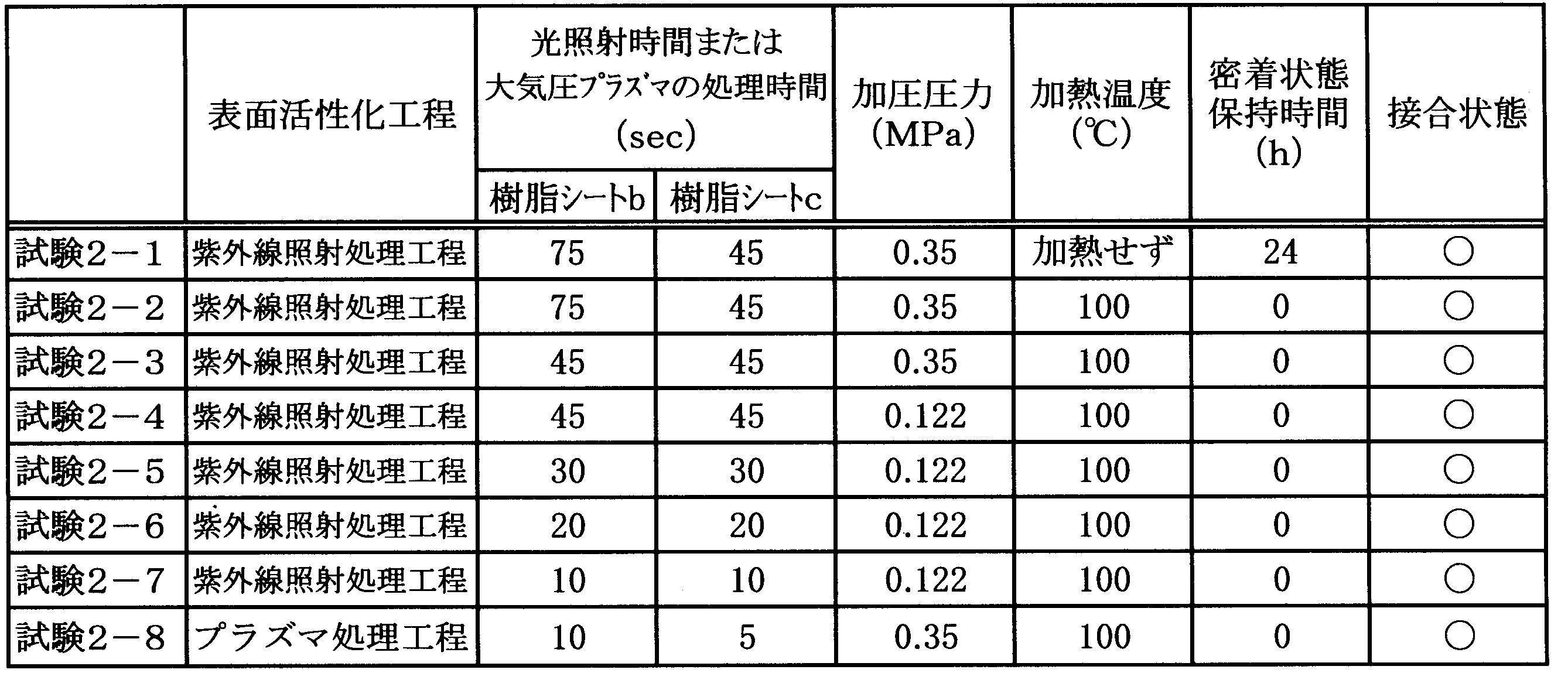
また、試験2-1の結果から、シリコーン樹脂よりなる樹脂シートbおよびシリコーン樹脂よりなる樹脂シートcを接合する場合には、加圧を解除した後に密着状態を24時間保持することにより、加熱することなしに良好な接合状態が得られることが理解される。その理由は明らかではないが,以下のように推測される。
真空紫外線が照射されて活性化された樹脂同士を密着させたとき、密着後加圧して樹脂の光照射面がほぼ均一に密着したとしても、密着直後は密着面における接合のための反応が当該密着面全面にわたって均一に発生しないことがある。このため、密着面における反応が比較的発生しにくい材料同士である場合には、反応領域が比較的狭く、その結果、両者の接合が十分に進行しにくい。従って、加圧を解除した直後においては、接合力が小さくて良好な接合状態が得られない可能性がある。しかしながら、密着面における接合のための反応は、比較的反応寿命が長く、樹脂材料における紫外線照射により活性化された表面同士が密着状態である場合には、反応は継続し、最終的には密着面全域にわたって接合が進行する。従って、仮に、加圧を解除した直後において接合が十分に進行していないときでも、24時間密着状態を保持することにより、密着面全域にわたって接合が進行すると考えられる。
これに対して、密着面における反応が比較的発生しやすい材料同士である場合には、反応領域が不均一に分布していても、反応領域が比較的広くなり、短時間で両者の接合が十分に進行すると考えられる。
また、試験2-8の結果から、樹脂シートbおよび樹脂シートcの接合においては、樹脂シートbの大気圧プラズマによる処理時間が10秒間以上で、樹脂シートcの大気圧プラズマによる処理時間が5秒間以上で、樹脂シートbおよび樹脂シートcの加圧において、加圧圧力が0.35MPa以上で、加熱温度が100℃であれば、加圧を解除した直後において良好な接合状態が得られることが理解される。
1.樹脂製チューブ
第1のチューブおよび第2のチューブとして、下記の樹脂製チューブを用意した。
第1のチューブは、シリコーン樹脂(Momentive Performance Materials社製)よりなるバルーン部用のものであり、外径は5.6mm、内径は5.3mm、全長は40mm、肉厚は0.15mmである。
第2のチューブは、シリコーン樹脂(Wacker Silicones社製)よりなるカテーテル部用のものであり、外径が7.3mm、内径が4.3mm、肉厚が1.5mmである。
また、第1のチューブは、その両端部の内周面に周方向に伸びる接合領域を有し、第2のチューブは、その外周面における第1のチューブの接続領域に対応する位置に周方向に伸びる接合領域を有する。第1のチューブおよび第2のチューブの各々の接合領域における軸方向の幅は10mmである。
第1のチューブ内に第2のチューブを、それぞれの接合領域が重なるよう挿入することにより、チューブ接合中間体を作製した。その後、チューブ接合中間体の第1のチューブにおける接合領域を含む部分を折り返すことにより、第1のチューブおよび第2のチューブの各々の接合領域を露出させた。そして、チューブ接合中間体を、第1のチューブおよび第2のチューブの各々の中心軸を回転軸として、約0.23回/秒の回転速度で回転させながら、図3に示す構成の光照射装置によって、第1のチューブおよび第2のチューブの各々の接合領域に光を照射することにより、紫外線照射処理工程を実行した。
以上において、紫外線ランプとしては、中心波長172nmの真空紫外線を照射するキセノンエキシマランプを使用し、紫外線透過窓としては、合成石英ガラスよりなるものを使用した。また、光照射の条件は下記の通りである。
紫外線透過窓からチューブ接合中間体までの距離:3mm
紫外線照射窓の外表面における照度:40mW/cm2
光照射時間:20秒間
チューブ接合中間体の周囲の雰囲気:大気
チューブ接合中間体における第1のチューブの折り返し部分を元の状態に戻すことにより、第1のチューブの接合領域と第2のチューブの接合領域とを互いに密着させた。そして、チューブ接合中間体を恒温槽内に配置し、加圧用治具を用いて、接合領域を含む部分を0.152MPaの加圧圧力で加圧しながら、100℃、150秒間の条件で加熱し、以て、第1のチューブと第2のチューブとを接合した。
得られたチューブ接合体における第1のチューブと第2のチューブとの間の間隙に、予め形成した空気注入口を介して空気を注入することにより、第1のチューブを膨張させてバルーンを形成した。この状態で、5分間放置したところ、空気が漏れることなく良好な接合状態が達成されていることが確認された。
また、第1のチューブおよび第2のチューブの接合領域を観察したところ、第1のチューブの接合領域と第2のチューブの接合領域との間に気泡等が存在せず、接合領域全域にわたって密着した状態で接合されていることが確認された。
第1のチューブおよび第2のチューブとして下記の樹脂製チューブを用い、密着工程において、接合領域を含む部分に対して加圧用治具による加圧を行わなかったこと以外は実施例1と同様にして、第1のチューブと第2のチューブとを接合した。
第1のチューブは、シリコーン樹脂(Momentive Performance Materials社製)よりなるバルーン部用のものであり、外径は6.7mm、内径は6.5mm、全長は40mm、肉厚は0.1mmである。
第2のチューブは、シリコーン樹脂(Wacker Silicones社製)よりなるカテーテル部用のものであり、外径が8mm、内径が5.0mm、肉厚が1.5mmである。
また、第1のチューブは、その両端部の内周面に周方向に伸びる接合領域を有し、第2のチューブは、その外周面における第1のチューブの接続領域に対応する位置に周方向に伸びる接合領域を有する。第1のチューブおよび第2のチューブの各々の接合領域における軸方向の幅は10mmである。
また、第1のチューブおよび第2のチューブの接合領域を観察したところ、第1のチューブの接合領域と第2のチューブの接合領域との間に気泡等が存在せず、接合領域全域にわたって密着した状態で接合されていることが確認された。
第1のチューブおよび第2のチューブとして下記の樹脂製チューブを用い、密着工程において、接合領域を含む部分に対して加圧用治具による加圧を行わなかったこと以外は実施例1と同様にして、第1のチューブと第2のチューブとを接合した。
第1のチューブは、シリコーン樹脂(Momentive Performance Materials社製)よりなるバルーン部用のものであり、外径は7.3mm、内径は7.0mm、肉厚は0.15mmである。
第2のチューブは、シリコーン樹脂(Wacker Silicones社製)よりなるカテーテル部用のものであり、外径が8mm、内径が5.0mm、肉厚が0.15mmである。
また、第1のチューブは、その両端部の内周面に周方向に伸びる接合領域を有し、第2のチューブは、その外周面における第1のチューブの接続領域に対応する位置に周方向に伸びる接合領域を有する。第1のチューブおよび第2のチューブの各々の接合領域における軸方向の幅は10mmである。
また、第1のチューブおよび第2のチューブの接合領域を観察したところ、第1のチューブの接合領域と第2のチューブの接合領域との間に僅かに気泡が存在することが確認された。
11 接合領域
15 チューブ接合中間体
20 第2のチューブ
21 接合領域
30 ランプハウス
31 紫外線透過窓
35 紫外線ランプ
40 マスク
41 透光部
42 遮光部
50 ケーシング
51 ガス供給口
52 ノズル
53 電極
54 誘電体層
55 高周波電源
56 マスク
57 通過部
58 遮蔽部
60 紫外線ランプ
61 放電容器
62 内側管
63 外側管
64 内側電極
65 外側電極
66 紫外線反射膜
67 高周波電源
AP 大気圧プラズマ
C 中心軸
L 光
S 放電空間
Claims (10)
- それぞれ合成樹脂らかなる第1のチューブおよび第2のチューブを接合する樹脂製チューブの接合方法であって、
前記第1のチューブの接合領域および前記第2のチューブの接合領域の各々を活性化する表面活性化工程と、
それぞれ前記表面活性化工程を経由した前記第1のチューブの接合領域および前記第2のチューブの接合領域を互いに密着させる密着工程と
を有することを特徴とする樹脂製チューブの接合方法。 - 前記表面活性化工程は、前記第1のチューブの接合領域および前記第2のチューブの接合領域の各々に、真空紫外線を含む光を照射する紫外線照射処理工程であることを特徴とする請求項1に記載の樹脂製チューブの接合方法。
- 前記表面活性化工程は、前記第1のチューブの接合領域および前記第2のチューブの接合領域の各々に、大気圧プラズマを接触させるプラズマ処理工程であることを特徴とする請求項1に記載の樹脂製チューブの接合方法。
- それぞれ合成樹脂らかなる第1のチューブおよび第2のチューブを接合する樹脂製チューブの接合方法であって、
内側管および外側管の間に放電空間が形成された二重管構造の放電容器を有し、当該内側管の内側方向に真空紫外線を含む光を放射するランプを用い、前記ランプの点灯中において、当該ランプの内側管内に、前記第1のチューブおよび前記第2のチューブの各々を、それぞれ接合領域が前記内側管に向いた状態で通過させることにより、第1のチューブおよび前記第2のチューブの各々の接合領域に光を照射して各接合領域を活性化する表面活性化工程と、
それぞれ前記表面活性化工程を経由した前記第1のチューブの接合領域および前記第2のチューブの接合領域を互いに密着させる密着工程と
を有することを特徴とする樹脂製チューブの接合方法。 - 前記第1のチューブはその内周面に前記接合領域を有すると共に、前記第2のチューブはその外周面に前記接合領域を有し、
前記表面活性化工程において、第1のチューブおよび第2のチューブの接合領域を表面活性化する前に、前記第1のチューブ内に前記第2のチューブを、それぞれの接合領域が重なるよう挿入し、その後、前記第1のチューブにおける接合領域を含む部分を折り返すことにより、前記第1のチューブの接合領域および前記第2のチューブの接合領域を露出させ、この状態で、前記第1のチューブの接合領域および前記第2のチューブの接合領域を活性化し、
その後、前記第1のチューブにおける折り返し部分を元に戻すことにより、前記密着工程を実行することを特徴とする請求項1乃至請求項4のいずれかに記載の樹脂製チューブの接合方法。 - 前記第1のチューブはその内周面に前記接合領域を有すると共に、前記第2のチューブはその外周面に前記接合領域を有し、
前記第1のチューブおよび前記第2のチューブの各々に対して、前記表面活性化工程を実行し、
前記密着工程において、前記第1のチューブの接合領域と前記第2のチューブの接合領域とが互いに接触せずに対向するよう、前記第1のチューブ内に前記第2のチューブを挿入し、その後、前記第1のチューブの接合領域と前記第2のチューブの接合領域と密着することを特徴とする請求項1乃至請求項4のいずれかに記載の樹脂製チューブの接合方法。 - 前記第1のチューブの内径が前記第2のチューブの外径より小さいものであることを特徴とする請求項5または請求項6に記載の樹脂製チューブの接合方法。
- 前記密着工程において、前記第1のチューブの接合領域と前記第2のチューブの接合領域との密着状態が、予め設定された時間保持されることを特徴とする請求項5乃至請求項7のいずれかに記載の樹脂製チューブの接合方法。
- 前記密着工程において、前記第1のチューブおよび前記第2のチューブの各々における互いに密着した接合領域を含む部分を厚み方向に加圧することを特徴とする請求項5乃至請求項8のいずれかに記載の樹脂製チューブの接合方法。
- 前記密着工程において、前記第1のチューブおよび前記第2のチューブの各々における互いに密着した接合領域を含む部分を厚み方向に加圧しながら加熱することを特徴とする請求項5乃至請求項8のいずれかに記載の樹脂製チューブの接合方法。
Priority Applications (3)
| Application Number | Priority Date | Filing Date | Title |
|---|---|---|---|
| CN201680016668.2A CN107428088B (zh) | 2015-03-19 | 2016-03-03 | 树脂制管的接合方法 |
| JP2016559654A JP6108047B2 (ja) | 2015-03-19 | 2016-03-03 | 樹脂製チューブの接合方法 |
| US15/559,394 US10500794B2 (en) | 2015-03-19 | 2016-03-03 | Method of joining resin tubes |
Applications Claiming Priority (2)
| Application Number | Priority Date | Filing Date | Title |
|---|---|---|---|
| JP2015-055677 | 2015-03-19 | ||
| JP2015055677 | 2015-03-19 |
Publications (1)
| Publication Number | Publication Date |
|---|---|
| WO2016147874A1 true WO2016147874A1 (ja) | 2016-09-22 |
Family
ID=56919835
Family Applications (1)
| Application Number | Title | Priority Date | Filing Date |
|---|---|---|---|
| PCT/JP2016/056527 Ceased WO2016147874A1 (ja) | 2015-03-19 | 2016-03-03 | 樹脂製チューブの接合方法 |
Country Status (4)
| Country | Link |
|---|---|
| US (1) | US10500794B2 (ja) |
| JP (1) | JP6108047B2 (ja) |
| CN (1) | CN107428088B (ja) |
| WO (1) | WO2016147874A1 (ja) |
Cited By (1)
| Publication number | Priority date | Publication date | Assignee | Title |
|---|---|---|---|---|
| JPWO2021176911A1 (ja) * | 2020-03-03 | 2021-09-10 |
Families Citing this family (10)
| Publication number | Priority date | Publication date | Assignee | Title |
|---|---|---|---|---|
| EP3994384B1 (en) | 2019-07-01 | 2025-05-21 | Saint-Gobain Performance Plastics Corporation | Profile connection |
| US11813417B2 (en) * | 2019-08-13 | 2023-11-14 | Medtronic Vascular, Inc. | Catheter modification device |
| BR112022011492A2 (pt) * | 2019-12-12 | 2022-08-23 | Saint Gobain Performance Plastics Corp | Aparelho para soldagem esterilizada |
| WO2021133762A1 (en) * | 2019-12-27 | 2021-07-01 | Saint-Gobain Performance Plastics Corporation | Profile disconnection |
| WO2021133677A1 (en) * | 2019-12-27 | 2021-07-01 | Saint-Gobain Performance Plastics Corporation | Profile connection |
| EP4121277A4 (en) | 2020-03-20 | 2024-04-10 | Saint-Gobain Performance Plastics Corporation | STERILE SEALING DEVICE |
| CN115916510A (zh) | 2020-06-19 | 2023-04-04 | 美国圣戈班性能塑料公司 | 复合制品和形成复合制品的方法 |
| JP7589661B2 (ja) * | 2021-09-10 | 2024-11-26 | ウシオ電機株式会社 | 誘電体バリア放電式プラズマ発生装置 |
| GB202203021D0 (en) * | 2022-03-04 | 2022-04-20 | Specialist Tooling Tech Limited | Method of affixing a sleeve to a rod- or tube-like member and an apparatus therefor |
| EP4574402A1 (de) | 2023-12-20 | 2025-06-25 | Hochschule für Angewandte Wissenschaft und Kunst Hildesheim/Holzminden/Göttingen | Verfahren zum verbinden von verbindungsbereichen aus silikon |
Citations (2)
| Publication number | Priority date | Publication date | Assignee | Title |
|---|---|---|---|---|
| JP2002524597A (ja) * | 1998-09-04 | 2002-08-06 | サイムド ライフ システムズ, インコーポレイテッド | ポリマーを結合させる方法及びこの方法により結合された材料を備えている医療機器 |
| JP2007312942A (ja) * | 2006-05-24 | 2007-12-06 | Terumo Corp | 医療器の製造方法 |
Family Cites Families (4)
| Publication number | Priority date | Publication date | Assignee | Title |
|---|---|---|---|---|
| EP1023913B1 (en) | 1997-10-08 | 2004-12-29 | Kaneka Corporation | Balloon catheter and method of production thereof |
| JP5223741B2 (ja) * | 2009-03-16 | 2013-06-26 | ウシオ電機株式会社 | エキシマランプ |
| JP2012101359A (ja) | 2010-11-05 | 2012-05-31 | Terumo Corp | 樹脂製連結チューブの製造方法、および樹脂製連結チューブ |
| DE102011051108A1 (de) * | 2011-06-16 | 2012-12-20 | Packsys Global (Switzerland) Ltd. | Verfahren zum Herstellen von Rohrkörpern für Verpackungstuben sowie Verpackungstube mit Rohrkörper |
-
2016
- 2016-03-03 US US15/559,394 patent/US10500794B2/en active Active
- 2016-03-03 CN CN201680016668.2A patent/CN107428088B/zh not_active Expired - Fee Related
- 2016-03-03 WO PCT/JP2016/056527 patent/WO2016147874A1/ja not_active Ceased
- 2016-03-03 JP JP2016559654A patent/JP6108047B2/ja not_active Expired - Fee Related
Patent Citations (2)
| Publication number | Priority date | Publication date | Assignee | Title |
|---|---|---|---|---|
| JP2002524597A (ja) * | 1998-09-04 | 2002-08-06 | サイムド ライフ システムズ, インコーポレイテッド | ポリマーを結合させる方法及びこの方法により結合された材料を備えている医療機器 |
| JP2007312942A (ja) * | 2006-05-24 | 2007-12-06 | Terumo Corp | 医療器の製造方法 |
Cited By (4)
| Publication number | Priority date | Publication date | Assignee | Title |
|---|---|---|---|---|
| JPWO2021176911A1 (ja) * | 2020-03-03 | 2021-09-10 | ||
| WO2021176911A1 (ja) * | 2020-03-03 | 2021-09-10 | 東レ株式会社 | 樹脂接合体の製造装置および樹脂接合体の製造方法 |
| US12151440B2 (en) * | 2020-03-03 | 2024-11-26 | Toray Industries, Inc. | Apparatus for producing joined-resin product and method for producing joined-resin product |
| JP7609060B2 (ja) | 2020-03-03 | 2025-01-07 | 東レ株式会社 | 樹脂接合体の製造装置および樹脂接合体の製造方法 |
Also Published As
| Publication number | Publication date |
|---|---|
| JP6108047B2 (ja) | 2017-04-05 |
| CN107428088B (zh) | 2020-07-14 |
| US10500794B2 (en) | 2019-12-10 |
| JPWO2016147874A1 (ja) | 2017-04-27 |
| CN107428088A (zh) | 2017-12-01 |
| US20180161554A1 (en) | 2018-06-14 |
Similar Documents
| Publication | Publication Date | Title |
|---|---|---|
| JP6108047B2 (ja) | 樹脂製チューブの接合方法 | |
| JP4857939B2 (ja) | 放電ランプ | |
| TWI451473B (zh) | Excimer lamp | |
| KR101213350B1 (ko) | 엑시머 램프 | |
| JP2016215183A (ja) | 紫外光照射装置 | |
| WO2014148325A1 (ja) | 蛍光エキシマランプおよび流体処理装置 | |
| JP6411478B2 (ja) | ポリイミドフィルムの製造方法、電子機器の製造方法および塗膜の剥離方法 | |
| JP5861989B2 (ja) | 紫外線放射蛍光ランプ | |
| JP2010027268A (ja) | エキシマランプ | |
| TW200937490A (en) | High-pressure discharge lamp, its manufacturing method, and light irradiation device | |
| CN101533753B (zh) | 高压放电灯以及光照射装置 | |
| KR101271344B1 (ko) | 형광 램프 및 이 형광 램프의 제조 방법 | |
| TWI493596B (zh) | Fluorescent light | |
| CN102214543B (zh) | 荧光灯及该荧光灯的制造方法 | |
| JP5278648B2 (ja) | エキシマランプ | |
| JP4502545B2 (ja) | エキシマランプ | |
| TWI903104B (zh) | 準分子燈、準分子燈之點燈方法以及準分子燈之製造方法 | |
| JP7343839B2 (ja) | フィラメントランプ | |
| US12176244B2 (en) | Method for bonding two substrates | |
| JPH1050269A (ja) | 無電極放電ランプ、無電極放電ランプ装置、無電極放電ランプ点灯装置及び流体処理装置 | |
| CN102709149A (zh) | 荧光灯及其制造方法 | |
| JP3562139B2 (ja) | 希ガス放電灯 | |
| JP4586766B2 (ja) | 光源装置 | |
| JPH10228862A (ja) | アパーチュア蛍光ランプの製造方法 | |
| JP2017069279A (ja) | 固体光源素子パッケージの製造方法 |
Legal Events
| Date | Code | Title | Description |
|---|---|---|---|
| ENP | Entry into the national phase |
Ref document number: 2016559654 Country of ref document: JP Kind code of ref document: A |
|
| 121 | Ep: the epo has been informed by wipo that ep was designated in this application |
Ref document number: 16764704 Country of ref document: EP Kind code of ref document: A1 |
|
| WWE | Wipo information: entry into national phase |
Ref document number: 15559394 Country of ref document: US |
|
| NENP | Non-entry into the national phase |
Ref country code: DE |
|
| 122 | Ep: pct application non-entry in european phase |
Ref document number: 16764704 Country of ref document: EP Kind code of ref document: A1 |