WO2016147865A1 - Two-motor vehicle drive device - Google Patents
Two-motor vehicle drive device Download PDFInfo
- Publication number
- WO2016147865A1 WO2016147865A1 PCT/JP2016/056368 JP2016056368W WO2016147865A1 WO 2016147865 A1 WO2016147865 A1 WO 2016147865A1 JP 2016056368 W JP2016056368 W JP 2016056368W WO 2016147865 A1 WO2016147865 A1 WO 2016147865A1
- Authority
- WO
- WIPO (PCT)
- Prior art keywords
- casing
- spacer
- bearing
- drive device
- motor vehicle
- Prior art date
Links
Images


Classifications
-
- B—PERFORMING OPERATIONS; TRANSPORTING
- B60—VEHICLES IN GENERAL
- B60K—ARRANGEMENT OR MOUNTING OF PROPULSION UNITS OR OF TRANSMISSIONS IN VEHICLES; ARRANGEMENT OR MOUNTING OF PLURAL DIVERSE PRIME-MOVERS IN VEHICLES; AUXILIARY DRIVES FOR VEHICLES; INSTRUMENTATION OR DASHBOARDS FOR VEHICLES; ARRANGEMENTS IN CONNECTION WITH COOLING, AIR INTAKE, GAS EXHAUST OR FUEL SUPPLY OF PROPULSION UNITS IN VEHICLES
- B60K1/00—Arrangement or mounting of electrical propulsion units
- B60K1/02—Arrangement or mounting of electrical propulsion units comprising more than one electric motor
-
- B—PERFORMING OPERATIONS; TRANSPORTING
- B60—VEHICLES IN GENERAL
- B60K—ARRANGEMENT OR MOUNTING OF PROPULSION UNITS OR OF TRANSMISSIONS IN VEHICLES; ARRANGEMENT OR MOUNTING OF PLURAL DIVERSE PRIME-MOVERS IN VEHICLES; AUXILIARY DRIVES FOR VEHICLES; INSTRUMENTATION OR DASHBOARDS FOR VEHICLES; ARRANGEMENTS IN CONNECTION WITH COOLING, AIR INTAKE, GAS EXHAUST OR FUEL SUPPLY OF PROPULSION UNITS IN VEHICLES
- B60K7/00—Disposition of motor in, or adjacent to, traction wheel
-
- F—MECHANICAL ENGINEERING; LIGHTING; HEATING; WEAPONS; BLASTING
- F16—ENGINEERING ELEMENTS AND UNITS; GENERAL MEASURES FOR PRODUCING AND MAINTAINING EFFECTIVE FUNCTIONING OF MACHINES OR INSTALLATIONS; THERMAL INSULATION IN GENERAL
- F16H—GEARING
- F16H1/00—Toothed gearings for conveying rotary motion
- F16H1/02—Toothed gearings for conveying rotary motion without gears having orbital motion
- F16H1/04—Toothed gearings for conveying rotary motion without gears having orbital motion involving only two intermeshing members
- F16H1/06—Toothed gearings for conveying rotary motion without gears having orbital motion involving only two intermeshing members with parallel axes
-
- F—MECHANICAL ENGINEERING; LIGHTING; HEATING; WEAPONS; BLASTING
- F16—ENGINEERING ELEMENTS AND UNITS; GENERAL MEASURES FOR PRODUCING AND MAINTAINING EFFECTIVE FUNCTIONING OF MACHINES OR INSTALLATIONS; THERMAL INSULATION IN GENERAL
- F16H—GEARING
- F16H57/00—General details of gearing
- F16H57/02—Gearboxes; Mounting gearing therein
- F16H57/021—Shaft support structures, e.g. partition walls, bearing eyes, casing walls or covers with bearings
- F16H57/022—Adjustment of gear shafts or bearings
Definitions
- the present invention relates to a two-motor vehicle drive device including two electric motors and a reduction gear for independently driving left and right drive wheels.
- a two-motor vehicle drive device in which two electric motors for independently driving left and right drive wheels and a speed reducer are integrated is disclosed in Patent Document 1.
- the left driving force is transmitted from the left motor to the drive shaft via the left row gear
- the right driving force is transmitted from the right motor to the drive shaft via the right row gear. Communicated.
- this type of two-motor vehicle drive device includes an electric motor for driving independently for each of the left and right drive wheels, it is used in a one-motor vehicle drive device that drives the left and right drive wheels with one electric motor.
- a differential gear or the like that distributes the driving force of one electric motor to the left and right is unnecessary.
- the two-motor vehicle drive device is provided with an electric motor for driving independently for each of the left and right drive wheels, it is easy to vary the drive force of the left and right drive wheels. By generating a large amount of driving force on the wheels on the outside of the turn, it is easy to improve running performance such as turning performance.
- the present applicant is examining the two-motor vehicle drive device 100 shown in FIG.
- the configuration of the two-motor vehicle drive device 100 is centered on a reduction gear casing 120 that houses two reduction gears 102L and 102R in parallel in the left and right directions, and two electric motors 101L and 101R on the left and right sides of the reduction gear casing 120.
- the left and right electric motors 101L and 101R are accommodated in the motor casings 103L and 103R.
- the reduction gear casing 120 in the two-motor vehicle drive device 100 has a structure divided into three casings, a central casing 120a and left and right side casings 120bL and 120bR, in order to hold the left and right rows of gears therein. Yes.
- a partition wall 121 is provided in the center of the center casing 120a.
- the reduction gear casing 120 is divided into left and right by the partition wall 121, and independent left and right accommodation chambers 122L and 122R for accommodating the two reduction gears 102L and 102R are provided in parallel.
- the reduction gears 102L and 102R are provided symmetrically and have an input shaft 123 having an input gear 123a to which power is transmitted from a motor shaft 112a, a large diameter gear 124a meshed with the input gear 123a, and a small diameter meshed with an output gear 125a.
- Both ends of the input shaft 123 of the speed reducers 102L and 102R are respectively connected to boss portions 127a formed on the left and right sides of the partition wall 121 of the central casing 120a and boss portions 127b formed on the side casings 120bL and 120bR via rolling bearings 128a and 128b. It is supported by rotation.
- the intermediate shaft 124 has a large-diameter gear 124a meshing with the input gear 123a and a small-diameter gear 124b meshing with the output gear 125a on the outer peripheral surface. Both ends of the intermediate shaft 124 are supported by rolling bosses 134a and 134b on bosses 132 formed on both surfaces of the partition wall 121 of the central casing 120a and bosses 133 formed on the side casings 120bL and 120bR.
- the output shaft 125 has a large-diameter output gear 125a and is supported by rolling bearings 137a and 137b on a boss portion 135 formed on both surfaces of the partition wall 121 of the central casing 120a and a boss portion 136 formed on the side casings 120bL and 120bR. Has been.
- the end of the output shaft 125 on the outboard side is drawn to the outside of the reduction gear casing 120 from the opening formed in the side casings 120bL and 120bR, and is drawn to the outer peripheral surface of the end of the output shaft 125 on the outboard side.
- the outer ring member of the constant velocity joint 115 is splined.
- the input shaft 123, the intermediate shaft 124, and the output shaft 125 which are the gear shafts of the speed reducers 102L and 102R, are supported by bearings.
- Each bearing is fitted in a bearing hole of each boss portion provided in the reduction gear casing 120.
- the inner ring of the bearing and the gear shafts 123, 124, and 125 are fitted with tightness (tight fitting) so that the gear shaft can rotate at the center of rotation, and the outer ring of the bearing and the bearing hole of each boss portion.
- the left and right input shafts 123 and 123 are arranged coaxially, but the most adjacent bearings 128 a and 128 a are processed independently of the boss portion 127 a provided on the partition wall 121.
- the bearing holes 127c and 127c are fitted.
- the spacer 150 is inserted into each bearing hole 127c, and the input shaft 123 to which the bearing 128a is attached is fitted into the bearing hole 127c of the boss 127a, and the wall of the bearing hole 127c and the outer ring end surface of the bearing 128a are fitted.
- the spacer 150 is sandwiched between and the axial play is adjusted.
- the thickness of the end play adjusting spacer 150 described above is the distance between the boss portion 127b provided on the side casing 120bL (or 120bR) and the boss portion 127a provided on the central casing 120a, that is, the bearing is applied. It is determined by the distance between contact and the axial length of the input shaft 123.
- the width (the length in the axial direction) of the gear / gear shaft is defined as a dimension a, and this dimension is measured.
- the width of the gear / gear shaft can be substituted by the assembly of the input shaft 123 and the bearings 128a and 128b and the bearing end face distance. Specifically, as shown in FIG. 14, with the input shaft 123 upright, the outer ring of the lower bearing 128a is supported from below, and the axial internal clearances of the bearings 128a and 128b are zero, The distance between the outer rings of the upper bearing 128b is measured, and this is defined as a dimension a.
- a spacer 150 having a suitable thickness is selected from the spacers 150 having different thicknesses and prepared.
- the spacer 150 for adjusting the end play of the input shaft 123 has been described as an example.
- the thickness of the spacer for adjusting the end play is calculated in the same manner for the intermediate shaft 124 and the output shaft 125.
- a spacer having a suitable thickness is used among the plurality of spacers having different thicknesses.
- the measurement of the dimension a can be easily performed by measuring the assembled input shaft 123 or the like.
- the thickness of the spacers for each six spacers are necessary, and there is a concern that wrong insertion of the spacers or selection errors may occur.
- the left and right bearing holes provided in the partition wall 121 have to be processed from both sides, and the processing cycle time becomes long, for example, by performing the processing by inverting the central casing 120a.
- This invention makes it a subject to provide the apparatus which can perform an operation
- the present invention includes two electric motors that independently drive the left and right drive wheels, and two speed reducers that individually decelerate the power of the two electric motors and transmit them to the left and right drive wheels.
- the speed reducer casing is a central casing.
- left and right side casings fixed to both side surfaces of the central casing.
- the central casing is provided with a partition wall in the center, and the reduction gear casing is divided into two storage chambers on the left and right by the partition wall.
- the shafts of the left and right speed reducers are coaxially arranged, and the axes of the speed reducers are respectively arranged on the partition walls of the side casing and the central casing.
- the boss portion of the partition wall of the central casing is supported by a bearing fitted in the bearing hole of the provided boss portion, and a bearing hole including through holes communicating with the left and right accommodation chambers is provided.
- a spacer is disposed between the bearings attached to the left and right shafts that are fitted into the bearing holes, and the end play adjustment is performed by sandwiching the spacers between the two bearings.
- the bearing hole provided in the boss portion of the partition wall is formed in a straight hole shape having a constant inner diameter.
- the spacer may be formed in a concave portion on the surface other than the portion that contacts the outer ring of the bearing.
- the spacer may be formed in a penetrating ring shape except for the abutting portion that abuts the outer ring of the bearing.
- the spacer can be configured by combining a disc-shaped member and a ring-shaped member formed in a penetrating ring shape except for a contact portion that contacts the outer ring of the bearing.
- end play can be adjusted by inserting spacers that also adjust the axial play between the left and right bearings fitted in the bearing holes provided in the partition wall of the central casing,
- One end play adjusting spacer can be used as one, and the number of parts can be reduced, the time required for measurement and assembly can be shortened, and further, work errors can be reduced, and the cost can be reduced.
- FIG. 1 It is a cross-sectional top view which shows embodiment of the 2 motor vehicle drive device which concerns on this invention. It is the cross-sectional top view to which the part of the reduction gear of embodiment of FIG. 1 was expanded. It is a top view of embodiment of FIG. It is a side view which shows the internal structure of the reduction gear on the right side in embodiment of FIG. It is a cross-sectional top view which shows the input shaft part of embodiment of FIG. It is sectional drawing to which some reduction gear casings of FIG. 1 were expanded, (a) has shown the left side casing, (b) has shown the center casing. It is explanatory drawing which shows the state which inserts a spacer and a bearing in the boss
- the spacer used for embodiment of FIG. 1 is shown, (a) is a perspective view, (b) is sectional drawing cut
- the other example of the spacer used for embodiment of FIG. 1 is shown, (a) is a perspective view, (b) is sectional drawing cut
- 1 shows still another example of the spacer used in the embodiment of FIG. 1, (a) is a perspective view, (b) is a cross-sectional view showing each part cut at the central part, and (c) is a center where each part is assembled. It is sectional drawing cut
- FIG. 13 is a transverse plan view showing an input shaft portion of the reference example of FIG. 12. It is sectional drawing to which some reduction gear casings of FIG. 12 were expanded, (a) has shown the left side casing, (b) has shown the center casing. It is explanatory drawing which shows the state which fits a spacer and a bearing in the boss
- the electric vehicle B shown in FIG. 11 is a rear wheel drive system, and drives the chassis 51, front wheels 52 as steering wheels, drive wheels (rear wheels) 53, and left and right drive wheels 53 independently.
- the two-motor vehicle drive device A is mounted on the chassis 51 at the center position of the left and right drive wheels 53 on the rear wheel side, and the drive force of the two-motor vehicle drive device A is constant speed. It is transmitted to the left and right drive wheels 53 via the joint 15 and the drive shaft 16.
- An inverter 9 that supplies electric power to the two-motor vehicle drive device A is installed at the center of the chassis 51.
- a front-wheel drive system and a four-wheel drive system may be used in addition to the rear-wheel drive system shown in FIG.
- the two-motor vehicle drive device A has a reduction gear casing 20 that houses two reduction gears 2L and 2R in parallel in the left and right directions.
- a structure in which motor casings 3L and 3R of two electric motors 1L and 1R are fixedly arranged on the left and right is adopted.
- the left and right electric motors 1L, 1R are accommodated in motor casings 3L, 3R as shown in FIG.
- the motor casings 3L and 3R include cylindrical motor casing bodies 3aL and 3aR, outer walls 3bL and 3bR that close the outer surfaces of the motor casing bodies 3aL and 3aR, and reduction gears on the inner surfaces of the motor casing bodies 3aL and 3aR. It consists of inner walls 3cL and 3cR separated from 2L and 2R.
- the electric motors 1 ⁇ / b> L and 1 ⁇ / b> R are of a radial gap type in which a stator 11 is provided on the inner peripheral surface of the motor casing body 3 aL and 3 aR, and a rotor 12 is provided on the inner periphery of the stator 11. I am using something.
- the electric motors 1L and 1R may be axial gap types.
- the rotor 12 has a motor shaft 12a at the center, and the motor shaft 12a is drawn from the openings of the inner side walls 3cL and 3cR of the motor casing bodies 3aL and 3aR to the speed reducers 2L and 2R, respectively.
- a seal member 13 is provided between the openings of the motor casing bodies 3aL and 3aR and the motor shaft 12a to prevent dust and muddy water from entering the electric motors 1L and 1R from the outside.
- the motor shaft 12a is rotatably supported by the rolling bearings 14a and 14b on the inner side walls 3cL and 3cR and the outer side walls 3bL and 3bR of the motor casing main bodies 3aL and 3aR (FIG. 1).
- the speed reducer casing 20 that accommodates two speed reducers 2L and 2R provided in parallel in the left and right has a three-piece structure of a central casing 20a and left and right side casings 20bL and 20bR fixed to both side surfaces of the central casing 20a. It has become.
- the left and right side casings 20bL and 20bR are formed in a right / left target shape.
- the left and right side casings 20bL and 20bR are fixed to the openings on both sides of the central casing 20a by a plurality of bolts 26L and 26R.
- the reduction gear Two electric motors 1L and 1R are fixedly arranged on the left and right sides of the casing 20 (FIGS. 1 and 3).
- the central casing 20a is provided with a partition wall 21 in the center.
- the reduction gear casing 20 is divided into two left and right by the partition wall 21, and independent left and right accommodation chambers 22L and 22R for accommodating the two reduction gears 2L and 2R are provided in parallel.
- the speed reducers 2L and 2R are provided symmetrically and have an input shaft 23 having an input gear 23a to which power is transmitted from the motor shaft 12a, and a large meshing with the input gear 23a.
- An intermediate shaft 24 having a small-diameter gear 24b meshing with the radial gear 24a and the output gear 25a, and an output gear 25a, which is pulled out from the speed reducer casing 20 and driven through the constant velocity joint 15 and the drive shaft 16 (see FIG. 11) and a parallel shaft gear reducer provided with an output shaft 25 for transmitting a driving force.
- the left and right input shafts 23, the intermediate shaft 24, and the output shaft 25 are arranged coaxially.
- Both ends of the input shaft 23 of the speed reducers 2L and 2R are connected to boss portions 27a formed on the left and right surfaces of the partition wall 21 of the central casing 20a and boss portions 27b formed on the side casings 20bL and 20bR via rolling bearings 28a and 28b. It is supported by rotation.
- the spacer 10 also serves to adjust the axial backlash between the left and right rolling bearings 28a, 28a fitted in the bearing holes 27c provided in the boss portions 27a formed in the partition wall 21 of the central casing 20a. Is inserted and the rolling bearings 28a, 28a are separated from each other. The end play is adjusted by the spacer 10.
- the end of the input shaft 23 on the outboard side is drawn out from the opening provided in the side casings 20bL and 20bR, and a seal member 31 is provided between the opening and the outer end of the input shaft 23.
- a seal member 31 is provided between the opening and the outer end of the input shaft 23.
- the input shaft 23 has a hollow structure, and the motor shaft 12a is inserted into the hollow input shaft 23.
- the input shaft 23 and the motor shaft 12a are spline-coupled (including serration coupling).
- the intermediate shaft 24 is a stepped gear having a large diameter gear 24a meshing with the input gear 23a and a small diameter gear 24b meshing with the output gear 25a on the outer peripheral surface. Both ends of the intermediate shaft 24 are supported by rolling bosses 34a and 34b on boss portions 32 formed on both surfaces of the partition wall 21 of the central casing 20a and boss portions 33 formed on the side casings 20bL and 20bR. As will be described later, the spacer 10 also serves to adjust the axial backlash between the left and right rolling bearings 34a, 34a fitted in the bearing holes 32c provided in the boss portion 32 formed in the partition wall 21 of the central casing 20a. Is inserted, and the rolling bearings 34a, 34a are separated from each other. The end play is adjusted by the spacer 10.
- the output shaft 25 has a large-diameter output gear 25a and is supported by rolling bearings 37a and 37b on a boss portion 35 formed on both surfaces of the partition wall 21 of the central casing 20a and a boss portion 36 formed on the side casings 20bL and 20bR.
- the spacer 10 also serves to adjust the axial backlash between the left and right rolling bearings 37a, 37a fitted in the bearing holes 35c provided in the boss portions 35 formed in the partition wall 21 of the central casing 20a. Is inserted, and the rolling bearings 37a and 37a are separated from each other. The end play is adjusted by the spacer 10.
- the end portion on the outboard side of the output shaft 25 is drawn to the outside of the speed reducer casing 20 from the opening formed in the side casings 20bL and 20bR, and the inner peripheral surface of the end portion on the outboard side of the output shaft 25 drawn out.
- the outer ring member of the constant velocity joint 15 is splined (including serration coupling).
- the constant velocity joint 15 coupled to the output shaft 25 is connected to the drive wheel 53 via the drive shaft 16 (see FIG. 11).
- a seal member 39 is provided between the end of the output shaft 25 on the outboard side and the openings formed in the side casings 20bL and 20bR to prevent leakage of the lubricating oil sealed in the speed reducers 2L and 2R. This prevents dust and muddy water from entering the reducers 2L and 2R from the outside.
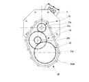
- FIG. 4 shows the right speed reducer 2R.
- the motor casings 3L and 3R of the left and right electric motors 1L and 1R have left and right motor casings on the outer surface of the end of the motor casing 3L and 3R on the outboard side (outside of the vehicle).
- a terminal box 5 for pulling out the UVW three-phase power line 4 is installed (see FIG. 11).
- the bearing hole 27c of each boss portion 27a provided in the partition wall 21 of the central casing 20a has an inner diameter that eliminates the flange where the rolling bearings 28a and 28a abut. It is formed in a certain straight hole shape, and is formed so that the accommodating chambers 22L and 22R communicate with each other.
- the spacer 10 is inserted into a straight hole-shaped bearing hole 27c provided in the partition wall 21 of the central casing 20a, and the rolling bearings 28a and 28a attached to the input shafts 23 and 23 are used as bearing holes.
- 27c is inserted from the left and right respectively.
- the end play is adjusted by sandwiching the spacer 10 between the rolling bearings 28a and 28a attached to the left and right input shafts 23 fitted in the bearing holes 27c.
- the thickness of the spacer 10 is determined by the dimensions of the parts to be assembled.
- the spacer 10 is inserted between the most adjacent rolling bearings 28a, 28a of the left and right input shafts 23, 23.
- the rolling bearings 28a, 28a are separated by a spacer 10 that also serves to adjust the axial play, and the end play is adjusted.
- the processing of the bearing holes 27d (see FIG. 2) provided in the boss portions 27b of the left and right casings 20bL and 20bR can be performed from one direction. Further, the processing of the bearing hole 27c provided in the partition wall 21 of the central casing 20a can also be performed from one direction because it has a straight hole shape with a constant inner diameter.
- the depth of the bearing hole of the boss portion 27a provided in the partition wall 21 can be substituted by the casing width of the central casing 20a. If the central casing 20a has an accurate overall width dimension, that is, if the parallelism of the left and right surfaces is good and the perpendicularity of the bearing hole 27c is good, the rolling bearings 28a and 28a will abut only by measuring the width dimension. It can be used to calculate the thickness of the spacer 10 that adjusts the end play that also serves as a part. When calculating the thickness of the spacer 10, the width of the central casing 20a is set as the dimension c (see FIG. 6B).
- the width of the gear / gear shaft of the input shaft 23 (length in the axial direction) is measured.
- the bearing end surface distance (a) obtained by assembling the input shaft 23 and the rolling bearings 28 a and 28 b is measured as the width between the rolling bearings.
- the input shaft 23 is upright, the outer ring of the lower rolling bearing 28a is supported from below, and the lower internal rolling is set with the axial internal clearance of the rolling bearings 28a, 28b being zero.
- the distance between the outer rings of the bearing 28a and the upper rolling bearing 28b is measured, and this is defined as a.
- the width of the left and right input shafts 23 is measured, the value measured on the right side is defined as a dimension aR, and the value measured on the left side is defined as a dimension aL.
- the distance between the end surfaces of the rolling bearings of the left and right casings 20bL (or 20bR) is defined as a dimension b1, and the respective lengths are measured.
- the value obtained by measuring the left side casing 20bL is defined as the dimension b1L
- the value obtained by measuring the right side casing 20bR is defined as the dimension b1R.
- the thickness of the spacer 10 can be determined based on the following equation.
- the central casing 20a can calculate the thickness of the spacer 10 that adjusts the end play that also serves as the flange portion against which the rolling bearings 28a and 28a abut only by measuring the width dimension.
- the measurement of the depth of the bearing hole 27c located in the central casing 20a can be omitted, and the number of measurement for measuring the thickness of the spacer 10 is also halved.
- the spacer 10 for adjustment is only provided between the bearings 28a and 28a, which reduces the number of parts, shortens the measurement and assembly time, and further reduces work errors, leading to cost reduction.
- the spacers 10 and 10 for adjusting the end play of the intermediate shaft 24 and the output shaft 25 are also provided in the same manner.
- the outer diameter of the spacer 10 is made slightly smaller than the inner diameter of the bearing hole of each shaft such as the bearing hole 27c, and is positioned concentrically within each bearing hole. If the spacer 10 has a disk shape, that is, if the end face is formed in a single plane, the rotating bearing inner ring and the output shaft may come into contact with each other, and rotation may be hindered or worn. Therefore, in the embodiment shown in FIG. 8, the end surface 10b other than the portion 10a that contacts the outer ring of the spacer end surface is formed as a recess so that the spacer 10 contacts only the outer ring of the rolling bearings 28a and 28a. As shown in b), the cross section is formed in an “I” shape.
- the spacer 10 shown in FIG. 9 is formed in a ring shape in which the portions other than the portion 10a contacting the outer ring of the rolling bearings 28a, 28a are formed so as to connect the receiving chambers 22L, 22R of the left and right speed reducers. ing.
- the ring shape so as to connect the left and right accommodation chambers 22L and 22R, the oil flowing into the vicinity of the bearing portion due to the splashing of the lubricating oil from the gears is allowed to flow to the left and right rolling bearings 28a. , 28a.
- a lubricating oil communication port (not shown) for communicating the speed reducers 2L, 2R is provided below the storage chambers 22L, 22R so that the lubricating oil is not biased to either of the two speed reducers 2L, 2R. . Further, even if the lubricating oil is biased to one of the speed reducers 2L, 2R due to centrifugal force or the like due to turning, the lubricating oil and the air are contained in the storage chamber 22L through the through hole of the lubricating oil communication port and the spacer 10 if the straight traveling state is achieved. The oil level of the left and right speed reducers 2L, 2R quickly becomes equal after moving back and forth through 22R.
- the thickness of the spacer 10 is adjusted by changing the type of combination, which is a combination of a disk-shaped spacer 10 c at the center and a ring-shaped spacer 10 d on both sides thereof. Can do.
- the disc-shaped spacer 10c and the ring-shaped spacer 10d can be cut out from a pipe and a round bar machined to a predetermined outer diameter, and combined into a spacer 10 by machining the end face.
- a through hole may be provided in the spacer 10 having the shape shown in FIG. 8 or the spacer 10 having the shape shown in FIG.
- Each bearing hole provided in the partition wall 21 of the central casing 20a, the outer diameter of the rolling bearing that supports each gear shaft fitted therein, and the spacer 10 of each shaft need to have different diameters for each gear shaft. No, two or more locations may have the same diameter.
- the spacers 10 having the same outer diameter can be used for a plurality of gear shafts, the types of spacers prepared with different outer diameters are reduced, management becomes easier, and further cost reduction can be achieved. it can.
Abstract
The present invention addresses the problem of providing a device with which end play can be easily adjusted, the number of components can be reduced, and labor can be easily performed. The device is provided with two electric motors 1L, 1R for independently driving left and right drive wheels, and two reduction gears 2L, 2R for individually reducing the motive power of the two electric motors 1L, 1R and transmitting said power to the left and right drive wheels. A reduction gear casing 20 houses the two reduction gears 2L, 2R in a left-right parallel layout, and the two electric motors are securely arranged to the left and right of the reduction gear casing 20. The reduction gear casing 20 comprises a center casing 20a, and left and right side-surface casings 20bL, 20bR secured to the side surfaces of the center casing 20a. The center casing 20a is provided with a partitioning wall 21 at the center thereof, and is divided by the partitioning wall 21 into two left-right housing chambers 22L, 22R. A bearing hole comprising a through-hole is provided to a boss part of the partitioning wall 21 of the center casing 20a. A spacer 10 is disposed between bearings 28a, 28a attached to left and right shafts fitted into the bearing holes of the center casing. The spacer 10 is sandwiched between the bearings 28a, 28a.
Description
この発明は、左右の駆動輪をそれぞれ独立して駆動させる2基の電動モータと減速機を備える2モータ車両駆動装置に関するものである。
The present invention relates to a two-motor vehicle drive device including two electric motors and a reduction gear for independently driving left and right drive wheels.
左右の駆動輪をそれぞれ独立して駆動させる2基の電動モータと減速機を一体化した2モータ車両駆動装置は、特許文献1に開示されている。この2モータ車両駆動装置は、左用の駆動力は、左側モータから左列の歯車を介してドライブシャフトまで伝達され、右用の駆動力は、右側モータから右列の歯車を介してドライブシャフトまで伝達される。
A two-motor vehicle drive device in which two electric motors for independently driving left and right drive wheels and a speed reducer are integrated is disclosed in Patent Document 1. In this two-motor vehicle drive device, the left driving force is transmitted from the left motor to the drive shaft via the left row gear, and the right driving force is transmitted from the right motor to the drive shaft via the right row gear. Communicated.
この種の2モータ車両駆動装置は、左右の駆動輪のそれぞれについて独立に駆動用の電動モータを備えるので、一つの電動モータによって左右の駆動輪を駆動させる1モータ車両駆動装置で使用される、一つの電動モータの駆動力を左右に振り分けるデファレンシャルギア等が不要になる、という利点を有する。
Since this type of two-motor vehicle drive device includes an electric motor for driving independently for each of the left and right drive wheels, it is used in a one-motor vehicle drive device that drives the left and right drive wheels with one electric motor. There is an advantage that a differential gear or the like that distributes the driving force of one electric motor to the left and right is unnecessary.
また、2モータ車両駆動装置は、左右の駆動輪のそれぞれについて独立に駆動用の電動モータを備えるので、左右の駆動輪の駆動力を異ならせることが容易であり、旋回時に旋回内側の車輪より旋回外側の車輪に多くの駆動力を発生させることで、旋回性能が向上する等の走行性能の向上が容易である。
In addition, since the two-motor vehicle drive device is provided with an electric motor for driving independently for each of the left and right drive wheels, it is easy to vary the drive force of the left and right drive wheels. By generating a large amount of driving force on the wheels on the outside of the turn, it is easy to improve running performance such as turning performance.
本出願人は、2モータ車両駆動装置100として、図12に示すものを検討している。この2モータ車両駆動装置100の構成は、2基の減速機102L、102Rを左右並列に収容する減速機ケーシング120を中央にして、その減速機ケーシング120の左右に2基の電動モータ101L、101Rのモータケーシング103L、103Rを固定配置する構造を採用し、左右の電動モータ101L、101Rは、モータケーシング103L、103R内に収容されている。
The present applicant is examining the two-motor vehicle drive device 100 shown in FIG. The configuration of the two-motor vehicle drive device 100 is centered on a reduction gear casing 120 that houses two reduction gears 102L and 102R in parallel in the left and right directions, and two electric motors 101L and 101R on the left and right sides of the reduction gear casing 120. The left and right electric motors 101L and 101R are accommodated in the motor casings 103L and 103R.
この2モータ車両駆動装置100における減速機ケーシング120は、内部に左右列の歯車を保持するために、中央ケーシング120aと、左右の側面ケーシング120bL、120bRの3つのケーシングに分割された構造になっている。
The reduction gear casing 120 in the two-motor vehicle drive device 100 has a structure divided into three casings, a central casing 120a and left and right side casings 120bL and 120bR, in order to hold the left and right rows of gears therein. Yes.
中央ケーシング120aには、中央に仕切り壁121が設けられている。減速機ケーシング120は、この仕切り壁121によって左右に2分割され、2基の減速機102L、102Rを収容する独立した左右の収容室122L、122Rが並列に設けられている。
A partition wall 121 is provided in the center of the center casing 120a. The reduction gear casing 120 is divided into left and right by the partition wall 121, and independent left and right accommodation chambers 122L and 122R for accommodating the two reduction gears 102L and 102R are provided in parallel.
減速機102L、102Rは、左右対称形に設けられ、モータ軸112aから動力が伝達される入力歯車123aを有する入力軸123と、この入力歯車123aに噛み合う大径歯車124aと出力歯車125aに噛み合う小径歯車124bを有する中間軸124と、出力歯車125aを有し、減速機ケーシング120から引き出されて駆動輪に駆動力を伝達する出力軸125とを備える。
The reduction gears 102L and 102R are provided symmetrically and have an input shaft 123 having an input gear 123a to which power is transmitted from a motor shaft 112a, a large diameter gear 124a meshed with the input gear 123a, and a small diameter meshed with an output gear 125a. An intermediate shaft 124 having a gear 124b and an output shaft 125 having an output gear 125a, which is pulled out from the reduction gear casing 120 and transmits driving force to driving wheels.
減速機102L、102Rの入力軸123の両端は、中央ケーシング120aの仕切り壁121の左右両面に形成したボス部127aと側面ケーシング120bL、120bRに形成したボス部127bに転がり軸受128a、128bを介して回転自在によって支持されている。
Both ends of the input shaft 123 of the speed reducers 102L and 102R are respectively connected to boss portions 127a formed on the left and right sides of the partition wall 121 of the central casing 120a and boss portions 127b formed on the side casings 120bL and 120bR via rolling bearings 128a and 128b. It is supported by rotation.
中間軸124は、外周面に入力歯車123aに噛み合う大径歯車124aと出力歯車125aに噛み合う小径歯車124bを有する。この中間軸124の両端は、中央ケーシング120aの仕切り壁121の両面に形成したボス部132と側面ケーシング120bL、120bRに形成したボス部133とに転がり軸受134a、134bを介して支持されている。
The intermediate shaft 124 has a large-diameter gear 124a meshing with the input gear 123a and a small-diameter gear 124b meshing with the output gear 125a on the outer peripheral surface. Both ends of the intermediate shaft 124 are supported by rolling bosses 134a and 134b on bosses 132 formed on both surfaces of the partition wall 121 of the central casing 120a and bosses 133 formed on the side casings 120bL and 120bR.
出力軸125は、大径の出力歯車125aを有し、中央ケーシング120aの仕切り壁121の両面に形成したボス部135と側面ケーシング120bL、120bRに形成したボス部136に転がり軸受137a、137bによって支持されている。
The output shaft 125 has a large-diameter output gear 125a and is supported by rolling bearings 137a and 137b on a boss portion 135 formed on both surfaces of the partition wall 121 of the central casing 120a and a boss portion 136 formed on the side casings 120bL and 120bR. Has been.
出力軸125のアウトボード側の端部は、側面ケーシング120bL、120bRに形成した開口部から減速機ケーシング120の外側に引き出され、引き出された出力軸125のアウトボード側の端部の外周面に、等速ジョイント115の外輪部材がスプライン結合されている。
The end of the output shaft 125 on the outboard side is drawn to the outside of the reduction gear casing 120 from the opening formed in the side casings 120bL and 120bR, and is drawn to the outer peripheral surface of the end of the output shaft 125 on the outboard side. The outer ring member of the constant velocity joint 115 is splined.
上記したように、減速機102L、102Rの歯車軸である入力軸123、中間軸124、出力軸125は、それぞれ軸受で支持される。各軸受は、減速機ケーシング120に設けられた各ボス部の軸受穴に嵌め込まれる。軸受の内輪と各歯車軸123、124、125は、歯車軸が回転中心で回転できるよう、締代を持って嵌合(タイト嵌合)しており、軸受の外輪と各ボス部の軸受穴は、各歯車軸の組込作業を容易となるよう、すきまを持って嵌合(ルーズ嵌合)している。
As described above, the input shaft 123, the intermediate shaft 124, and the output shaft 125, which are the gear shafts of the speed reducers 102L and 102R, are supported by bearings. Each bearing is fitted in a bearing hole of each boss portion provided in the reduction gear casing 120. The inner ring of the bearing and the gear shafts 123, 124, and 125 are fitted with tightness (tight fitting) so that the gear shaft can rotate at the center of rotation, and the outer ring of the bearing and the bearing hole of each boss portion. Are fitted with a clearance (loose fitting) to facilitate the assembling of each gear shaft.
ここで各歯車軸支持軸受の外輪がルーズ嵌合であることより、駆動時の騒音や振動の低減、軸受穴の摩耗防止などの観点から、歯車軸の軸方向のガタつき、即ち、エンドプレイを小さくする必要がある。このため、図13で示すように、ボス部127aの軸受穴127cに軸受128aの外輪端面と挟み込むようにスペーサ150を入れ、エンドプレイを調整している。図13は、入力軸123の仕切り壁121に形成したボス部127a部分を拡大して示しているが、中間軸124、出力軸125についても同様に、エンドプレイ調整用のスペーサが挿入されている。
Here, since the outer ring of each gear shaft support bearing is loosely fitted, from the viewpoint of reducing noise and vibration during driving and preventing wear of the bearing hole, the play of the gear shaft in the axial direction, that is, end play is achieved. Need to be small. For this reason, as shown in FIG. 13, the spacer 150 is inserted into the bearing hole 127c of the boss portion 127a so as to be sandwiched between the outer ring end face of the bearing 128a and the end play is adjusted. 13 shows an enlarged view of the boss portion 127a formed on the partition wall 121 of the input shaft 123. Similarly, end play adjusting spacers are also inserted in the intermediate shaft 124 and the output shaft 125. FIG. .
図12、図13に示すように、左右の入力軸123、123が同軸に配置されているが、最も隣接した軸受128a、128aは、仕切り壁121に設けられたボス部127aに独立して加工された軸受穴127c、127cに嵌め込まれる。図16に示すように、各軸受穴127cにそれぞれスペーサ150を挿入し、軸受128aが取り付けられた入力軸123をボス部127aの軸受穴127cに嵌め込み、軸受穴127cの壁と軸受128aの外輪端面とでスペーサ150を挟み込み、軸方向ガタを調整している。
As shown in FIGS. 12 and 13, the left and right input shafts 123 and 123 are arranged coaxially, but the most adjacent bearings 128 a and 128 a are processed independently of the boss portion 127 a provided on the partition wall 121. The bearing holes 127c and 127c are fitted. As shown in FIG. 16, the spacer 150 is inserted into each bearing hole 127c, and the input shaft 123 to which the bearing 128a is attached is fitted into the bearing hole 127c of the boss 127a, and the wall of the bearing hole 127c and the outer ring end surface of the bearing 128a are fitted. The spacer 150 is sandwiched between and the axial play is adjusted.
上記したエンドプレイ調整用のスペーサ150の厚さは、側面ケーシング120bL(又は120bR)に設けられたボス部127bと中央ケーシング120aに設けられたボス部127aとの間の距離、即ち、軸受が当接する間の距離と、入力軸123の軸方向長さとにより決められる。
The thickness of the end play adjusting spacer 150 described above is the distance between the boss portion 127b provided on the side casing 120bL (or 120bR) and the boss portion 127a provided on the central casing 120a, that is, the bearing is applied. It is determined by the distance between contact and the axial length of the input shaft 123.
図14及び図15に従い、これら測定すべき箇所について説明する。歯車・歯車軸の幅(軸方向の長さ)を寸法aとし、この寸法を測定する。この歯車・歯車軸の幅は、図14で示すように、入力軸123と軸受128a、128bを組み立て、その軸受端面距離でも代用することができる。詳しくは、図14に示すように入力軸123を直立させ、下部となる軸受128aの外輪を下方より支持し、軸受128a、128bの軸方向内部すきまを0とした状態で、下部の軸受128aと上部の軸受128bの外輪間距離を測定し、これを寸法aとする。そして、図15(a)(b)に示すように、側面ケーシング120bL(又は120bR)に設けられたボス部127bの軸受が当接する部分とケーシング端面間寸法b1、中央ケーシング120aに設けられたボス部127aのスペーサ150を介して軸受が当接する部分とケーシング端面間寸法b2を測定する。
Referring to FIGS. 14 and 15, these measurement points will be described. The width (the length in the axial direction) of the gear / gear shaft is defined as a dimension a, and this dimension is measured. As shown in FIG. 14, the width of the gear / gear shaft can be substituted by the assembly of the input shaft 123 and the bearings 128a and 128b and the bearing end face distance. Specifically, as shown in FIG. 14, with the input shaft 123 upright, the outer ring of the lower bearing 128a is supported from below, and the axial internal clearances of the bearings 128a and 128b are zero, The distance between the outer rings of the upper bearing 128b is measured, and this is defined as a dimension a. And as shown to Fig.15 (a) (b), the part which the bearing of the boss | hub part 127b provided in the side casing 120bL (or 120bR) contact | abuts, the dimension b1 between casing end surfaces, and the boss | hub provided in the center casing 120a The dimension b2 between the portion where the bearing abuts through the spacer 150 of the portion 127a and the casing end surface is measured.
これらの測定結果から以下の式により、スペーサ150の厚さが算出される。スペーサの厚さ=(b1+b2)-a-α(α:許容すきま)
From the measurement results, the thickness of the spacer 150 is calculated by the following equation. Spacer thickness = (b1 + b2)-a-α (α: Allowable clearance)
許容すきまαには範囲があり、厚さ違いで複数種類が用意されたスペーサ150の中から、適した厚さのものを選択し使用する。
¡There is a range in the allowable clearance α, and a spacer 150 having a suitable thickness is selected from the spacers 150 having different thicknesses and prepared.
上記では、入力軸123のエンドプレイ調整用のスペーサ150を例に挙げて説明したが、中間軸124、出力軸125についても同様にして、エンドプレイ調整用のスペーサの厚さが算出され、用意された厚さ違いの複数のスペーサの中から、適した厚さのものが使用される。
In the above description, the spacer 150 for adjusting the end play of the input shaft 123 has been described as an example. However, the thickness of the spacer for adjusting the end play is calculated in the same manner for the intermediate shaft 124 and the output shaft 125. A spacer having a suitable thickness is used among the plurality of spacers having different thicknesses.
ところで、上記の寸法aの測定は、組み立てた入力軸123等を立てて測定すれば容易に行える。しかし、上記した寸法b1、b2の測定については、ケーシングの接合面を基準にそれぞれの穴深さを測る必要があり、例えば、減速機が三軸あるものでは、片輪で6箇所、左右合わせて12箇所を精度よく測定せねばならず、その測定の難易度も高く、時間も嵩む。更に、それぞれにスペーサの厚さを設定するために、6枚のスペーサが必要であり、スペーサの入れ間違いや選択間違いを生じる懸念がある。
By the way, the measurement of the dimension a can be easily performed by measuring the assembled input shaft 123 or the like. However, for the measurement of the above dimensions b1 and b2, it is necessary to measure the depth of each hole with reference to the joint surface of the casing. 12 locations must be measured with high accuracy, and the measurement is difficult and time consuming. Furthermore, in order to set the thickness of the spacers for each, six spacers are necessary, and there is a concern that wrong insertion of the spacers or selection errors may occur.
また、仕切り壁121に設けられた左右の軸受穴は、両側から加工しなければならず、中央ケーシング120aを反転させて加工を行うなど、その加工サイクルタイムが長くなる。
Also, the left and right bearing holes provided in the partition wall 121 have to be processed from both sides, and the processing cycle time becomes long, for example, by performing the processing by inverting the central casing 120a.
この発明は、上記した点に鑑み、エンドプレイの調整を容易にすると共に、部品点数を減らし、作業を容易に行うことができる装置を提供することを課題とする。
This invention makes it a subject to provide the apparatus which can perform an operation | work easily, making it easy to adjust an end play and reducing the number of parts in view of the above-mentioned point.
この発明は、左右の駆動輪をそれぞれ独立に駆動させる2基の電動モータと、この2基の電動モータの動力を個別に減速して左右の駆動輪に伝達する2基の減速機とを備え、この2基の減速機を左右並列に収容する減速機ケーシングを中央にしてその左右に2基の電動モータのモータケーシングを固定配置した2モータ車両駆動装置において、前記減速機ケーシングは、中央ケーシングとこの中央ケーシングの両側面に固定される左右の側面ケーシングからなり、前記中央ケーシングには、中央に仕切り壁が設けられ、前記減速機ケーシングは、この仕切り壁によって左右に2つの収容室に分割され、前記左右の減速機の各軸同士がそれぞれ同軸に配置され、前記減速機の各軸は、前記側面ケーシングと中央ケーシングの仕切り壁にそれぞれ設けられたボス部の軸受穴に嵌め込まれた軸受で支持され、前記中央ケーシングの仕切り壁のボス部には、左右の収容室と連通する貫通穴からなる軸受穴が設けられ、前記中央ケーシングの軸受穴に嵌め込まれる左右の軸に取り付けられた軸受間にスペーサを配し、このスペーサを両軸受で挟み込んで、エンドプレイ調整が行われることを特徴とする。
The present invention includes two electric motors that independently drive the left and right drive wheels, and two speed reducers that individually decelerate the power of the two electric motors and transmit them to the left and right drive wheels. In the two-motor vehicle drive device in which the motor casings of the two electric motors are fixedly arranged on the left and right sides of the speed reducer casing that accommodates the two speed reducers in parallel in the left and right, the speed reducer casing is a central casing. And left and right side casings fixed to both side surfaces of the central casing. The central casing is provided with a partition wall in the center, and the reduction gear casing is divided into two storage chambers on the left and right by the partition wall. The shafts of the left and right speed reducers are coaxially arranged, and the axes of the speed reducers are respectively arranged on the partition walls of the side casing and the central casing. The boss portion of the partition wall of the central casing is supported by a bearing fitted in the bearing hole of the provided boss portion, and a bearing hole including through holes communicating with the left and right accommodation chambers is provided. A spacer is disposed between the bearings attached to the left and right shafts that are fitted into the bearing holes, and the end play adjustment is performed by sandwiching the spacers between the two bearings.
前記仕切り壁のボス部に設けられる軸受穴は、内径が一定のストレート穴形状に形成されていることを特徴とする。
The bearing hole provided in the boss portion of the partition wall is formed in a straight hole shape having a constant inner diameter.
また、前記スペーサは、軸受の外輪と当接する部分以外の面は、凹部に形成すればよい。
Further, the spacer may be formed in a concave portion on the surface other than the portion that contacts the outer ring of the bearing.
また、前記スペーサは、軸受の外輪と当接する当接部以外は貫通しているリング形状に形成すればよい。
Further, the spacer may be formed in a penetrating ring shape except for the abutting portion that abuts the outer ring of the bearing.
前記スペーサは、円板状部材と、軸受の外輪と当接する当接部以外は貫通しているリング形状に形成されたリング状部材を組み合わせて構成することができる。
The spacer can be configured by combining a disc-shaped member and a ring-shaped member formed in a penetrating ring shape except for a contact portion that contacts the outer ring of the bearing.
この発明では、中央ケーシングの仕切り壁に設けられた軸受穴に嵌め込まれる左右の軸受の間に、軸方向ガタの調整も兼ねるスペーサを挿入して、エンドプレイを調整することできるので、左右の軸のエンドプレイ調整用のスペーサを1つで兼ねることができ、部品点数を削減でき、計測、組立時間の短縮、更に、作業ミスの低減となり、コストを低減することができる。
In this invention, since the end play can be adjusted by inserting spacers that also adjust the axial play between the left and right bearings fitted in the bearing holes provided in the partition wall of the central casing, One end play adjusting spacer can be used as one, and the number of parts can be reduced, the time required for measurement and assembly can be shortened, and further, work errors can be reduced, and the cost can be reduced.
以下、この発明の実施の形態を添付図面に基づいて説明する。
Hereinafter, embodiments of the present invention will be described with reference to the accompanying drawings.
図11に示す電気自動車Bは、後輪駆動方式であり、シャーシ51と、操舵輪としての前輪52と、駆動輪(後輪)53と、左右の駆動輪53をそれぞれに独立に駆動する2モータ車両駆動装置Aとを備え、2モータ車両駆動装置Aは、後輪側の左右の駆動輪53の中央位置のシャーシ51上に搭載され、2モータ車両駆動装置Aの駆動力は、等速ジョイント15とドライブシャフト16を介して左右の駆動輪53に伝達される。シャーシ51の中央部には、2モータ車両駆動装置Aに電力を供給するインバータ9が設置されている。
The electric vehicle B shown in FIG. 11 is a rear wheel drive system, and drives the chassis 51, front wheels 52 as steering wheels, drive wheels (rear wheels) 53, and left and right drive wheels 53 independently. The two-motor vehicle drive device A is mounted on the chassis 51 at the center position of the left and right drive wheels 53 on the rear wheel side, and the drive force of the two-motor vehicle drive device A is constant speed. It is transmitted to the left and right drive wheels 53 via the joint 15 and the drive shaft 16. An inverter 9 that supplies electric power to the two-motor vehicle drive device A is installed at the center of the chassis 51.
2モータ車両駆動装置Aの搭載形態としては、図11に示す後輪駆動方式、以外に前輪駆動方式、四輪駆動方式でもよい。
As a mounting form of the two-motor vehicle drive device A, a front-wheel drive system and a four-wheel drive system may be used in addition to the rear-wheel drive system shown in FIG.
この発明に係る2モータ車両駆動装置Aは、図1~図4に示すように、2基の減速機2L、2Rを左右並列に収容する減速機ケーシング20を中央にし、その減速機ケーシング20の左右に2基の電動モータ1L、1Rのモータケーシング3L、3Rを固定配置した構造を採用する。
As shown in FIGS. 1 to 4, the two-motor vehicle drive device A according to the present invention has a reduction gear casing 20 that houses two reduction gears 2L and 2R in parallel in the left and right directions. A structure in which motor casings 3L and 3R of two electric motors 1L and 1R are fixedly arranged on the left and right is adopted.
左右の電動モータ1L、1Rは、図1に示すように、モータケーシング3L、3R内に収容されている。
The left and right electric motors 1L, 1R are accommodated in motor casings 3L, 3R as shown in FIG.
モータケーシング3L、3Rは、円筒形のモータケーシング本体3aL、3aRと、このモータケーシング本体3aL、3aRの外側面を閉塞する外側壁3bL、3bRと、モータケーシング本体3aL、3aRの内側面に減速機2L、2Rと隔てる内側壁3cL、3cRとからなる。
The motor casings 3L and 3R include cylindrical motor casing bodies 3aL and 3aR, outer walls 3bL and 3bR that close the outer surfaces of the motor casing bodies 3aL and 3aR, and reduction gears on the inner surfaces of the motor casing bodies 3aL and 3aR. It consists of inner walls 3cL and 3cR separated from 2L and 2R.
電動モータ1L、1Rは、図1に示すように、モータケーシング本体3aL、3aRの内周面にステータ11を設け、このステータ11の内周に間隔をおいてロータ12を設けたラジアルギャップタイプのものを使用している。なお、図示はしなかったが電動モータ1L、1Rは、アキシャルギャップタイプのものを使用してもよい。
As shown in FIG. 1, the electric motors 1 </ b> L and 1 </ b> R are of a radial gap type in which a stator 11 is provided on the inner peripheral surface of the motor casing body 3 aL and 3 aR, and a rotor 12 is provided on the inner periphery of the stator 11. I am using something. Although not shown, the electric motors 1L and 1R may be axial gap types.
ロータ12は、モータ軸12aを中心部に有し、そのモータ軸12aはモータケーシング本体3aL、3aRの内側壁3cL、3cRの開口部からそれぞれ減速機2L、2R側に引き出されている。モータケーシング本体3aL、3aRの開口部とモータ軸12aとの間にはシール部材13が設けられ、外部から電動モータ1L、1Rの内部への埃や泥水の侵入を防止している。
The rotor 12 has a motor shaft 12a at the center, and the motor shaft 12a is drawn from the openings of the inner side walls 3cL and 3cR of the motor casing bodies 3aL and 3aR to the speed reducers 2L and 2R, respectively. A seal member 13 is provided between the openings of the motor casing bodies 3aL and 3aR and the motor shaft 12a to prevent dust and muddy water from entering the electric motors 1L and 1R from the outside.
モータ軸12aは、モータケーシング本体3aL、3aRの内側壁3cL、3cRと外側壁3bL、3bRとに転がり軸受14a、14bによって回転自在に支持されている(図1)。
The motor shaft 12a is rotatably supported by the rolling bearings 14a and 14b on the inner side walls 3cL and 3cR and the outer side walls 3bL and 3bR of the motor casing main bodies 3aL and 3aR (FIG. 1).
左右並列に設けられた2基の減速機2L、2Rを収容する減速機ケーシング20は、中央ケーシング20aとこの中央ケーシング20aの両側面に固定される左右の側面ケーシング20bL、20bRの3ピース構造になっている。左右の側面ケーシング20bL、20bRは、左右対象形状に形成されている。
The speed reducer casing 20 that accommodates two speed reducers 2L and 2R provided in parallel in the left and right has a three-piece structure of a central casing 20a and left and right side casings 20bL and 20bR fixed to both side surfaces of the central casing 20a. It has become. The left and right side casings 20bL and 20bR are formed in a right / left target shape.
左右の側面ケーシング20bL、20bRは、図3に示すように、中央ケーシング20aの両側面の開口部に、複数のボルト26L、26Rによって固定されている。
As shown in FIG. 3, the left and right side casings 20bL and 20bR are fixed to the openings on both sides of the central casing 20a by a plurality of bolts 26L and 26R.
減速機ケーシング20の側面ケーシング20bL、20bRのアウトボード側の側面と電動モータ1L、1Rのモータケーシング本体3aL、3aRの内側壁3cL、3cRとを、複数のボルト29によって固定することにより、減速機ケーシング20の左右に2基の電動モータ1L、1Rが固定配置されている(図1及び図3)。
By fixing the side surface of the side casings 20bL and 20bR of the reduction gear casing 20 on the outboard side and the inner side walls 3cL and 3cR of the motor casing bodies 3aL and 3aR of the electric motors 1L and 1R by a plurality of bolts 29, the reduction gear Two electric motors 1L and 1R are fixedly arranged on the left and right sides of the casing 20 (FIGS. 1 and 3).
中央ケーシング20aには、中央に仕切り壁21が設けられている。減速機ケーシング20は、この仕切り壁21によって左右に2分割され、2基の減速機2L、2Rを収容する独立した左右の収容室22L、22Rが並列に設けられている。
The central casing 20a is provided with a partition wall 21 in the center. The reduction gear casing 20 is divided into two left and right by the partition wall 21, and independent left and right accommodation chambers 22L and 22R for accommodating the two reduction gears 2L and 2R are provided in parallel.
減速機2L、2Rは、図1及び図2に示すように、左右対称形に設けられ、モータ軸12aから動力が伝達される入力歯車23aを有する入力軸23と、この入力歯車23aに噛み合う大径歯車24aと出力歯車25aに噛み合う小径歯車24bを有する中間軸24と、出力歯車25aを有し、減速機ケーシング20から引き出されて等速ジョイント15、ドライブシャフト16を介して駆動輪53(図11参照)に駆動力を伝達する出力軸25とを備える平行軸歯車減速機である。左右の入力軸23、中間軸24、出力軸25はそれぞれ同軸に配置されている。
As shown in FIGS. 1 and 2, the speed reducers 2L and 2R are provided symmetrically and have an input shaft 23 having an input gear 23a to which power is transmitted from the motor shaft 12a, and a large meshing with the input gear 23a. An intermediate shaft 24 having a small-diameter gear 24b meshing with the radial gear 24a and the output gear 25a, and an output gear 25a, which is pulled out from the speed reducer casing 20 and driven through the constant velocity joint 15 and the drive shaft 16 (see FIG. 11) and a parallel shaft gear reducer provided with an output shaft 25 for transmitting a driving force. The left and right input shafts 23, the intermediate shaft 24, and the output shaft 25 are arranged coaxially.
減速機2L、2Rの入力軸23の両端は、中央ケーシング20aの仕切り壁21の左右両面に形成したボス部27aと側面ケーシング20bL、20bRに形成したボス部27bに転がり軸受28a、28bを介して回転自在によって支持されている。中央ケーシング20aの仕切り壁21に形成されたボス部27aに設けられた軸受穴27cに嵌め込まれる左右の転がり軸受28a、28aの間には、後述するように、軸方向ガタの調整も兼ねるスペーサ10が挿入され、互いの転がり軸受28a、28aは離間されている。このスペーサ10によりエンドプレイが調整される。
Both ends of the input shaft 23 of the speed reducers 2L and 2R are connected to boss portions 27a formed on the left and right surfaces of the partition wall 21 of the central casing 20a and boss portions 27b formed on the side casings 20bL and 20bR via rolling bearings 28a and 28b. It is supported by rotation. As will be described later, the spacer 10 also serves to adjust the axial backlash between the left and right rolling bearings 28a, 28a fitted in the bearing holes 27c provided in the boss portions 27a formed in the partition wall 21 of the central casing 20a. Is inserted and the rolling bearings 28a, 28a are separated from each other. The end play is adjusted by the spacer 10.
入力軸23のアウトボード側の端部は、側面ケーシング20bL、20bRに設けた開口部から外側に引き出されており、開口部と入力軸23の外側端部との間にはシール部材31を設け、減速機2L、2Rに封入された潤滑油の漏洩を防止するとともに、外部から減速機2L、2Rの内部への埃や泥水の侵入を防止している。
The end of the input shaft 23 on the outboard side is drawn out from the opening provided in the side casings 20bL and 20bR, and a seal member 31 is provided between the opening and the outer end of the input shaft 23. In addition, leakage of the lubricating oil sealed in the speed reducers 2L and 2R is prevented, and entry of dust and muddy water from the outside into the speed reducers 2L and 2R is prevented.
入力軸23は、中空構造であり、この中空の入力軸23にモータ軸12aが挿入されている。入力軸23とモータ軸12aとは、スプライン結合(セレーション結合も含む)されている。
The input shaft 23 has a hollow structure, and the motor shaft 12a is inserted into the hollow input shaft 23. The input shaft 23 and the motor shaft 12a are spline-coupled (including serration coupling).
中間軸24は、外周面に入力歯車23aに噛み合う大径歯車24aと出力歯車25aに噛み合う小径歯車24bを有する段付き歯車である。この中間軸24の両端は、中央ケーシング20aの仕切り壁21の両面に形成したボス部32と側面ケーシング20bL、20bRに形成したボス部33とに転がり軸受34a、34bを介して支持されている。中央ケーシング20aの仕切り壁21に形成されたボス部32に設けられた軸受穴32cに嵌め込まれる左右の転がり軸受34a、34aの間には、後述するように、軸方向ガタの調整も兼ねるスペーサ10が挿入され、互いの転がり軸受34a、34aは離間されている。このスペーサ10によりエンドプレイが調整される。
The intermediate shaft 24 is a stepped gear having a large diameter gear 24a meshing with the input gear 23a and a small diameter gear 24b meshing with the output gear 25a on the outer peripheral surface. Both ends of the intermediate shaft 24 are supported by rolling bosses 34a and 34b on boss portions 32 formed on both surfaces of the partition wall 21 of the central casing 20a and boss portions 33 formed on the side casings 20bL and 20bR. As will be described later, the spacer 10 also serves to adjust the axial backlash between the left and right rolling bearings 34a, 34a fitted in the bearing holes 32c provided in the boss portion 32 formed in the partition wall 21 of the central casing 20a. Is inserted, and the rolling bearings 34a, 34a are separated from each other. The end play is adjusted by the spacer 10.
出力軸25は、大径の出力歯車25aを有し、中央ケーシング20aの仕切り壁21の両面に形成したボス部35と側面ケーシング20bL、20bRに形成したボス部36に転がり軸受37a、37bによって支持されている。中央ケーシング20aの仕切り壁21に形成されたボス部35に設けられた軸受穴35cに嵌め込まれる左右の転がり軸受37a、37aの間には、後述するように、軸方向ガタの調整も兼ねるスペーサ10が挿入され、互いの転がり軸受37a、37aは離間されている。このスペーサ10によりエンドプレイが調整される。
The output shaft 25 has a large-diameter output gear 25a and is supported by rolling bearings 37a and 37b on a boss portion 35 formed on both surfaces of the partition wall 21 of the central casing 20a and a boss portion 36 formed on the side casings 20bL and 20bR. Has been. As will be described later, the spacer 10 also serves to adjust the axial backlash between the left and right rolling bearings 37a, 37a fitted in the bearing holes 35c provided in the boss portions 35 formed in the partition wall 21 of the central casing 20a. Is inserted, and the rolling bearings 37a and 37a are separated from each other. The end play is adjusted by the spacer 10.
出力軸25のアウトボード側の端部は、側面ケーシング20bL、20bRに形成した開口部から減速機ケーシング20の外側に引き出され、引き出された出力軸25のアウトボード側の端部の内周面に、等速ジョイント15の外輪部材がスプライン結合(セレーション結合を含む)されている。
The end portion on the outboard side of the output shaft 25 is drawn to the outside of the speed reducer casing 20 from the opening formed in the side casings 20bL and 20bR, and the inner peripheral surface of the end portion on the outboard side of the output shaft 25 drawn out. In addition, the outer ring member of the constant velocity joint 15 is splined (including serration coupling).
出力軸25に結合された等速ジョイント15は、ドライブシャフト16を介して駆動輪53に接続される(図11参照)。
The constant velocity joint 15 coupled to the output shaft 25 is connected to the drive wheel 53 via the drive shaft 16 (see FIG. 11).
出力軸25のアウトボード側の端部と側面ケーシング20bL、20bRに形成した開口部との間には、シール部材39を設け、減速機2L、2Rに封入された潤滑油の漏洩を防止するとともに、外部から減速機2L、2Rの内部への埃や泥水の侵入を防止している。
A seal member 39 is provided between the end of the output shaft 25 on the outboard side and the openings formed in the side casings 20bL and 20bR to prevent leakage of the lubricating oil sealed in the speed reducers 2L and 2R. This prevents dust and muddy water from entering the reducers 2L and 2R from the outside.
減速機2L、2Rの入力軸23、中間軸24、出力軸25の歯車の配置は、図4に示すとおりである。図4は、右側の減速機2Rを示している。
The arrangement of the gears of the input shaft 23, the intermediate shaft 24, and the output shaft 25 of the speed reducers 2L and 2R is as shown in FIG. FIG. 4 shows the right speed reducer 2R.
左右2基の電動モータ1L、1Rのモータケーシング3L、3Rには、図1に示すように、モータケーシング3L、3Rのアウトボード側(車両の外側)の端部外面には、左右のモータケーシングからUVWの3相の動力線4を引き出す端子ボックス5が設置されている(図11参照)。
As shown in FIG. 1, the motor casings 3L and 3R of the left and right electric motors 1L and 1R have left and right motor casings on the outer surface of the end of the motor casing 3L and 3R on the outboard side (outside of the vehicle). A terminal box 5 for pulling out the UVW three-phase power line 4 is installed (see FIG. 11).
次に、中央ケーシング20aの仕切り壁21に形成された各ボス部に設けられた軸受穴に挿入されるスペーサについて説明する。ここでは、入力軸23が支持される仕切り壁21に形成したボス部27aを中心として説明するが、中間軸24、出力軸25を支持するボス部も同様であるので、ここでは、説明を割愛する。
Next, the spacer inserted into the bearing hole provided in each boss part formed in the partition wall 21 of the central casing 20a will be described. Here, the description will focus on the boss portion 27a formed on the partition wall 21 on which the input shaft 23 is supported, but the boss portion supporting the intermediate shaft 24 and the output shaft 25 is also the same, so the description is omitted here. To do.
この発明においては、図2及び図7に示すように、中央ケーシング20aの仕切り壁21に設けられた各ボス部27aの軸受穴27cを、転がり軸受28a、28aが突き当たる鍔部をなくした内径が一定のストレートの穴形状に形成し、収容室22L、22Rが連通するように形成されている。
In the present invention, as shown in FIGS. 2 and 7, the bearing hole 27c of each boss portion 27a provided in the partition wall 21 of the central casing 20a has an inner diameter that eliminates the flange where the rolling bearings 28a and 28a abut. It is formed in a certain straight hole shape, and is formed so that the accommodating chambers 22L and 22R communicate with each other.
図7に示すように、中央ケーシング20aの仕切り壁21に設けられるストレートの穴形状の軸受穴27cに、スペーサ10を挿入し、入力軸23、23に取り付けられた転がり軸受28a、28aを軸受穴27cに左右からそれぞれ嵌め込む。軸受穴27cに嵌め込まれる左右の入力軸23にそれぞれ取り付けられた転がり軸受28a、28aの間に、スペーサ10を挟み込むことで、エンドプレイを調整している。このスペーサ10の厚さは、組み付ける各部品の寸法により決められる。
As shown in FIG. 7, the spacer 10 is inserted into a straight hole-shaped bearing hole 27c provided in the partition wall 21 of the central casing 20a, and the rolling bearings 28a and 28a attached to the input shafts 23 and 23 are used as bearing holes. 27c is inserted from the left and right respectively. The end play is adjusted by sandwiching the spacer 10 between the rolling bearings 28a and 28a attached to the left and right input shafts 23 fitted in the bearing holes 27c. The thickness of the spacer 10 is determined by the dimensions of the parts to be assembled.
このように、左右の入力軸23、23の最も隣接した転がり軸受28a、28aの間には、スペーサ10が挿入されることになる。転がり軸受28a、28aの間は、軸方向ガタの調整も兼ねるスペーサ10により離間され、そしてエンドプレイが調整されている。
Thus, the spacer 10 is inserted between the most adjacent rolling bearings 28a, 28a of the left and right input shafts 23, 23. The rolling bearings 28a, 28a are separated by a spacer 10 that also serves to adjust the axial play, and the end play is adjusted.
そして、左右のケーシング20bL、20bRのボス部27bに設けられる軸受穴27d(図2参照)の加工は、一方向から行える。また、中央ケーシング20aの仕切り壁21に設けられる軸受穴27cの加工も、内径が一定のストレートの穴形状であるので、一方向から加工を行うことができる。
And the processing of the bearing holes 27d (see FIG. 2) provided in the boss portions 27b of the left and right casings 20bL and 20bR can be performed from one direction. Further, the processing of the bearing hole 27c provided in the partition wall 21 of the central casing 20a can also be performed from one direction because it has a straight hole shape with a constant inner diameter.
次に、スペーサ10の厚さを決めるための各部品の寸法の算出につき説明する。仕切り壁21に設けられたボス部27aの軸受穴の深さは、中央ケーシング20aのケーシング幅で代用することできる。中央ケーシング20aは全体の幅寸法が精度よく形成されている、即ち、左右面の平行度が良く、軸受穴27cの直角度が良ければ、幅寸法測定のみで、転がり軸受28a、28aが突き当たる鍔部を兼ねたエンドプレイを調整するスペーサ10の厚さの算出に使用できる。スペーサ10の厚さを算出する際には、中央ケーシング20aの幅を寸法cとしている(図6(b)参照)。
Next, calculation of the dimensions of each component for determining the thickness of the spacer 10 will be described. The depth of the bearing hole of the boss portion 27a provided in the partition wall 21 can be substituted by the casing width of the central casing 20a. If the central casing 20a has an accurate overall width dimension, that is, if the parallelism of the left and right surfaces is good and the perpendicularity of the bearing hole 27c is good, the rolling bearings 28a and 28a will abut only by measuring the width dimension. It can be used to calculate the thickness of the spacer 10 that adjusts the end play that also serves as a part. When calculating the thickness of the spacer 10, the width of the central casing 20a is set as the dimension c (see FIG. 6B).
図5に示すように、入力軸23の歯車・歯車軸の幅(軸方向の長さ)を計測する。この図5では、転がり軸受間の幅として、入力軸23と転がり軸受28a、28bを組み立てた軸受端面距離(a)を計測する。詳しくは、図5に示すように入力軸23を直立させ、下部となる転がり軸受28aの外輪を下方より支持し、転がり軸受28a、28bの軸方向内部すきまを0とした状態で、下部の転がり軸受28aと上部の転がり軸受28bの外輪間距離を測定し、これをaとする。この発明では、左右の入力軸23の幅を計測するので、右側を計測した値を寸法aR、左側を計測した値を寸法aLとする。
As shown in FIG. 5, the width of the gear / gear shaft of the input shaft 23 (length in the axial direction) is measured. In FIG. 5, the bearing end surface distance (a) obtained by assembling the input shaft 23 and the rolling bearings 28 a and 28 b is measured as the width between the rolling bearings. Specifically, as shown in FIG. 5, the input shaft 23 is upright, the outer ring of the lower rolling bearing 28a is supported from below, and the lower internal rolling is set with the axial internal clearance of the rolling bearings 28a, 28b being zero. The distance between the outer rings of the bearing 28a and the upper rolling bearing 28b is measured, and this is defined as a. In the present invention, since the width of the left and right input shafts 23 is measured, the value measured on the right side is defined as a dimension aR, and the value measured on the left side is defined as a dimension aL.
そして、図6(a)に示すように、左右のケーシング20bL(または20bR)の転がり軸受の端面間距離を寸法b1とし、それぞれの長さを測定する。この発明では、左右のケーシング20bL(または20bR)の長さを計測するので、左の側面ケーシング20bLを計測した値を寸法b1L、右の側面ケーシング20bRを計測した値を寸法b1Rとしている。
Then, as shown in FIG. 6 (a), the distance between the end surfaces of the rolling bearings of the left and right casings 20bL (or 20bR) is defined as a dimension b1, and the respective lengths are measured. In this invention, since the length of the left and right casings 20bL (or 20bR) is measured, the value obtained by measuring the left side casing 20bL is defined as the dimension b1L, and the value obtained by measuring the right side casing 20bR is defined as the dimension b1R.
これら計測した測定値に基づき、スペーサ10の厚さを、以下の式に基づき決定することができる。
Based on these measured values, the thickness of the spacer 10 can be determined based on the following equation.
スペーサの厚さ=(c+b1L+b1R)-aL-aR-α(α:許容すきま)
Spacer thickness = (c + b1L + b1R) -aL-aR-α (α: Allowable clearance)
この発明では、左右の側面ケーシング20bLおよび20bRの軸受穴深さ寸法b1L、b1Rの測定と、左右の入力軸23の軸受端面距離の寸法aL、aRの測定は必要である。しかし、中央ケーシング20aは、幅寸法測定のみで、転がり軸受28a、28aが突き当たる鍔部を兼ねたエンドプレイを調整するスペーサ10の厚さを算出することができる。
In the present invention, measurement of the bearing hole depth dimensions b1L and b1R of the left and right side casings 20bL and 20bR and measurement of the bearing end surface distance dimensions aL and aR of the left and right input shafts 23 are necessary. However, the central casing 20a can calculate the thickness of the spacer 10 that adjusts the end play that also serves as the flange portion against which the rolling bearings 28a and 28a abut only by measuring the width dimension.
そして、中央ケーシング20aに位置する軸受穴27cの深さの測定を省略することができ、スペーサ10の厚さを測定するための計測回数も半分になる。また、調整のためのスペーサ10も軸受28a、28aの間に設けるだけであり、部品点数の削減、計測、組立時間の短縮、更に、作業ミスの低減となり、コスト低減につながる。
And the measurement of the depth of the bearing hole 27c located in the central casing 20a can be omitted, and the number of measurement for measuring the thickness of the spacer 10 is also halved. Moreover, the spacer 10 for adjustment is only provided between the bearings 28a and 28a, which reduces the number of parts, shortens the measurement and assembly time, and further reduces work errors, leading to cost reduction.
中間軸24、出力軸25のエンドプレイ調整用のスペーサ10、10も同様にして設けられる。
The spacers 10 and 10 for adjusting the end play of the intermediate shaft 24 and the output shaft 25 are also provided in the same manner.
次に、スペーサ10の形状につき、図8から図10を参照して説明する。スペーサ10の外径は、軸受穴27c等の各軸の軸受穴の内径に対し、僅かに小さく作られており、各軸受穴内で同心良く位置するようになっている。スペーサ10を円板形状とすると、即ち、端面が単一平面に形成されていると、回転する軸受内輪や出力軸とも接触し、回転を阻害したり、摩耗したりする虞がある。そこで、図8に示す実施形態では、スペーサ10は転がり軸受28a、28aの外輪のみと当接するように、スペーサ端面の外輪と当接する部分10a以外の端面10bは凹部に形成され、同図8(b)に示すように、断面「I」型に形成している。
Next, the shape of the spacer 10 will be described with reference to FIGS. The outer diameter of the spacer 10 is made slightly smaller than the inner diameter of the bearing hole of each shaft such as the bearing hole 27c, and is positioned concentrically within each bearing hole. If the spacer 10 has a disk shape, that is, if the end face is formed in a single plane, the rotating bearing inner ring and the output shaft may come into contact with each other, and rotation may be hindered or worn. Therefore, in the embodiment shown in FIG. 8, the end surface 10b other than the portion 10a that contacts the outer ring of the spacer end surface is formed as a recess so that the spacer 10 contacts only the outer ring of the rolling bearings 28a and 28a. As shown in b), the cross section is formed in an “I” shape.
図9に示すスペーサ10は、転がり軸受28a、28aの外輪と当接する部分10a以外の部分は貫通しているリング状に形成し、左右の減速機の収容室22L、22Rを繋ぐように形成されている。このように、左右の収容室22L、22Rを繋ぐように貫通するリング状に形成することで、歯車からの潤滑油の跳ね掛けにより、軸受部近傍へ流入してきた油を、左右の転がり軸受28a、28aのどちらにも流し入れることができる。この場合は、潤滑油が2基の減速機2L、2Rのどちらかに偏らないように、収容室22L、22Rの下部に減速機2L、2Rを連通する潤滑油連通口(図示省略)を設ける。また、旋回走行による遠心力等で減速機2L、2Rのどちらかに潤滑油が偏っても、直進状態となれば潤滑油連通口とスペーサ10の貫通穴により潤滑油と空気が収容室22L、22Rを行き来し、速やかに左右の減速機2L、2Rの油面は等しくなる。
The spacer 10 shown in FIG. 9 is formed in a ring shape in which the portions other than the portion 10a contacting the outer ring of the rolling bearings 28a, 28a are formed so as to connect the receiving chambers 22L, 22R of the left and right speed reducers. ing. In this way, by forming the ring shape so as to connect the left and right accommodation chambers 22L and 22R, the oil flowing into the vicinity of the bearing portion due to the splashing of the lubricating oil from the gears is allowed to flow to the left and right rolling bearings 28a. , 28a. In this case, a lubricating oil communication port (not shown) for communicating the speed reducers 2L, 2R is provided below the storage chambers 22L, 22R so that the lubricating oil is not biased to either of the two speed reducers 2L, 2R. . Further, even if the lubricating oil is biased to one of the speed reducers 2L, 2R due to centrifugal force or the like due to turning, the lubricating oil and the air are contained in the storage chamber 22L through the through hole of the lubricating oil communication port and the spacer 10 if the straight traveling state is achieved. The oil level of the left and right speed reducers 2L, 2R quickly becomes equal after moving back and forth through 22R.
図10に示す実施形態は、中央部に円板状のスペーサ10cと、その両側にリング状のスペーサ10dを組み合わせたものである、組合せの種類を変えることで、スペーサ10の厚みを調整することができる。
In the embodiment shown in FIG. 10, the thickness of the spacer 10 is adjusted by changing the type of combination, which is a combination of a disk-shaped spacer 10 c at the center and a ring-shaped spacer 10 d on both sides thereof. Can do.
円板状のスペーサ10cと、リング状のスペーサ10dは、所定外径に加工されたパイプと丸棒から切り出して、端面の加工で組合せてスペーサ10とすることができる。
The disc-shaped spacer 10c and the ring-shaped spacer 10d can be cut out from a pipe and a round bar machined to a predetermined outer diameter, and combined into a spacer 10 by machining the end face.
図8に示す形状のスペーサ10、あるいは図10に示す形状のスペーサ10に、貫通穴を設けてもよい。
A through hole may be provided in the spacer 10 having the shape shown in FIG. 8 or the spacer 10 having the shape shown in FIG.
中央ケーシング20aの仕切り壁21に設けられた各軸受穴、そこへ嵌合する各歯車軸を支持する転がり軸受の外径、および各軸のスペーサ10は、それぞれの歯車軸で異なる径である必要は無く、2か所以上が同じ径であってもよい。この場合には、複数の歯車軸に外径が同じスペーサ10を使用することが可能となり、異なる外径で用意するスペーサの種類が削減され、管理が容易となり、更なるコスト低減とすることができる。
Each bearing hole provided in the partition wall 21 of the central casing 20a, the outer diameter of the rolling bearing that supports each gear shaft fitted therein, and the spacer 10 of each shaft need to have different diameters for each gear shaft. No, two or more locations may have the same diameter. In this case, the spacers 10 having the same outer diameter can be used for a plurality of gear shafts, the types of spacers prepared with different outer diameters are reduced, management becomes easier, and further cost reduction can be achieved. it can.
この発明は前述した実施形態に何ら限定されるものではなく、この発明の要旨を逸脱しない範囲において、更に種々の形態で実施し得ることは勿論のことであり、この発明の範囲は、特許請求の範囲によって示され、更に特許請求の範囲に記載の均等の意味、および範囲内の全ての変更を含む。
The present invention is not limited to the above-described embodiments, and can of course be implemented in various forms without departing from the gist of the present invention. The scope of the present invention is claimed. And the equivalent meanings recited in the claims, and all modifications within the scope are included.
1L、1R 電動モータ
2L、2R 減速機
3L、3R モータケーシング
10 スペーサ
11 ステータ
12 ロータ
12a モータ軸
13 シール部材
14a、14b 転がり軸受
15 等速ジョイント
16 ドライブシャフト
20 減速機ケーシング
20a 中央ケーシング
20bL、20bR 側面ケーシング
21 仕切り壁
22L、22R 収容室
23 入力軸
23a 入力歯車
24 中間軸
24a 大径歯車
24b 小径歯車
25 出力軸
25a 出力歯車
26L、26R、29 ボルト
27a、27b、32、33、35、36 ボス部
27c、27d、32c、35c 軸受穴
28a、28b、34a、34b、37a、37b 転がり軸受
31,39 シール部材
53 駆動輪 1L, 1R Electric motor 2L, 2R Reducer 3L, 3R Motor casing 10 Spacer 11 Stator 12 Rotor 12a Motor shaft 13 Seal member 14a, 14b Rolling bearing 15 Constant velocity joint 16 Drive shaft 20 Reducer casing 20a Central casing 20bL, 20bR Side surface Casing 21 Partition walls 22L, 22R Storage chamber 23 Input shaft 23a Input gear 24 Intermediate shaft 24a Large diameter gear 24b Small diameter gear 25 Output shaft 25a Output gear 26L, 26R, 29 Bolts 27a, 27b, 32, 33, 35, 36 Boss 27c, 27d, 32c, 35c Bearing holes 28a, 28b, 34a, 34b, 37a, 37b Rolling bearings 31, 39 Seal member 53 Drive wheel
2L、2R 減速機
3L、3R モータケーシング
10 スペーサ
11 ステータ
12 ロータ
12a モータ軸
13 シール部材
14a、14b 転がり軸受
15 等速ジョイント
16 ドライブシャフト
20 減速機ケーシング
20a 中央ケーシング
20bL、20bR 側面ケーシング
21 仕切り壁
22L、22R 収容室
23 入力軸
23a 入力歯車
24 中間軸
24a 大径歯車
24b 小径歯車
25 出力軸
25a 出力歯車
26L、26R、29 ボルト
27a、27b、32、33、35、36 ボス部
27c、27d、32c、35c 軸受穴
28a、28b、34a、34b、37a、37b 転がり軸受
31,39 シール部材
53 駆動輪 1L,
Claims (5)
- 左右の駆動輪をそれぞれ独立に駆動させる2基の電動モータと、この2基の電動モータの動力を個別に減速して左右の駆動輪に伝達する2基の減速機とを備え、この2基の減速機を左右並列に収容する減速機ケーシングを中央にしてその左右に2基の電動モータのモータケーシングを固定配置した2モータ車両駆動装置において、
前記減速機ケーシングは、中央ケーシングとこの中央ケーシングの両側面に固定される左右の側面ケーシングからなり、
前記中央ケーシングには、中央に仕切り壁が設けられ、前記減速機ケーシングは、この仕切り壁によって左右に2つの収容室に分割され、
前記左右の減速機の各軸同士がそれぞれ同軸に配置され、前記減速機の各軸は、前記側面ケーシングと中央ケーシングの仕切り壁にそれぞれ設けられたボス部の軸受穴に嵌め込まれた軸受で支持され、
前記中央ケーシングの仕切り壁のボス部には、左右の収容室と連通する貫通穴からなる軸受穴が設けられ、
前記中央ケーシングの軸受穴に嵌め込まれる左右の軸に取り付けられた軸受間にスペーサを配し、このスペーサを両軸受で挟み込んで、エンドプレイ調整が行われることを特徴とする2モータ車両駆動装置。 Two electric motors for independently driving the left and right driving wheels, and two reduction gears for individually decelerating the power of the two electric motors and transmitting them to the left and right driving wheels. A two-motor vehicle drive device in which a motor casing of two electric motors is fixedly arranged on the left and right sides of a speed reducer casing that accommodates the speed reducers in parallel in the left and right,
The reduction gear casing is composed of a central casing and left and right side casings fixed to both side surfaces of the central casing.
The central casing is provided with a partition wall in the center, and the speed reducer casing is divided into two storage chambers on the left and right by the partition wall,
The shafts of the left and right speed reducers are arranged coaxially, and each axis of the speed reducer is supported by a bearing fitted in a bearing hole of a boss portion provided in each of the partition walls of the side casing and the central casing. And
The boss portion of the partition wall of the central casing is provided with a bearing hole composed of a through hole communicating with the left and right accommodation chambers,
A two-motor vehicle drive device characterized in that end play adjustment is performed by arranging a spacer between the bearings attached to the left and right shafts fitted in the bearing holes of the central casing, and sandwiching the spacer between the two bearings. - 前記仕切り壁のボス部に設けられる軸受穴は、内径が一定のストレート穴形状に形成されていることを特徴とする請求項1に記載の2モータ車両駆動装置。 The two-motor vehicle drive device according to claim 1, wherein the bearing hole provided in the boss portion of the partition wall is formed in a straight hole shape having a constant inner diameter.
- 前記スペーサは、軸受の外輪と当接する部分以外の面は、凹部に形成されていることを特徴とする請求項1又は2に記載の2モータ車両駆動装置。 3. The two-motor vehicle drive device according to claim 1, wherein a surface of the spacer other than a portion in contact with the outer ring of the bearing is formed as a recess.
- 前記スペーサは、軸受の外輪と当接する当接部以外は貫通しているリング形状に形成されていることを特徴とする請求項1又は2に記載の2モータ車両駆動装置。 3. The two-motor vehicle drive device according to claim 1, wherein the spacer is formed in a ring shape that penetrates except for a contact portion that contacts the outer ring of the bearing.
- 前記スペーサは、円板状部材と、軸受の外輪と当接する当接部以外は貫通しているリング形状に形成されたリング状部材を組み合わせた構成したことを特徴とする請求項1又は2に記載の2モータ車両駆動装置。 3. The spacer according to claim 1, wherein the spacer is formed by combining a disc-shaped member and a ring-shaped member formed in a penetrating ring shape except for a contact portion that contacts the outer ring of the bearing. The two-motor vehicle drive device described.
Applications Claiming Priority (2)
| Application Number | Priority Date | Filing Date | Title |
|---|---|---|---|
| JP2015055841A JP6449061B2 (en) | 2015-03-19 | 2015-03-19 | Two-motor vehicle drive device |
| JP2015-055841 | 2015-03-19 |
Publications (1)
| Publication Number | Publication Date |
|---|---|
| WO2016147865A1 true WO2016147865A1 (en) | 2016-09-22 |
Family
ID=56920363
Family Applications (1)
| Application Number | Title | Priority Date | Filing Date |
|---|---|---|---|
| PCT/JP2016/056368 WO2016147865A1 (en) | 2015-03-19 | 2016-03-02 | Two-motor vehicle drive device |
Country Status (2)
| Country | Link |
|---|---|
| JP (1) | JP6449061B2 (en) |
| WO (1) | WO2016147865A1 (en) |
Cited By (5)
| Publication number | Priority date | Publication date | Assignee | Title |
|---|---|---|---|---|
| CN108116219A (en) * | 2017-11-17 | 2018-06-05 | 深圳先进技术研究院 | A kind of electric power device |
| DE202019103781U1 (en) * | 2019-07-09 | 2020-10-12 | Hofer Powertrain Innovation Gmbh | Twin gearbox with a double input shaft |
| DE202019103770U1 (en) * | 2019-07-09 | 2020-10-14 | Hofer Powertrain Innovation Gmbh | Double gear with advantageous overhang |
| DE102020118194A1 (en) * | 2019-07-09 | 2021-01-14 | Hofer Powertrain Innovation Gmbh | Twin gearbox with a double input shaft |
| WO2021005175A1 (en) | 2019-07-09 | 2021-01-14 | Hofer Powertrain Innovation Gmbh | Double gearbox |
Citations (3)
| Publication number | Priority date | Publication date | Assignee | Title |
|---|---|---|---|---|
| JP2000324767A (en) * | 1999-05-12 | 2000-11-24 | Honda Motor Co Ltd | Motor, and front and rear-wheeled vehicle |
| JP2001025289A (en) * | 1999-07-09 | 2001-01-26 | Honda Motor Co Ltd | Method for checking energizing of motor |
| JP2010048379A (en) * | 2008-08-22 | 2010-03-04 | Aisin Aw Co Ltd | Vehicle drive device |
-
2015
- 2015-03-19 JP JP2015055841A patent/JP6449061B2/en not_active Expired - Fee Related
-
2016
- 2016-03-02 WO PCT/JP2016/056368 patent/WO2016147865A1/en active Application Filing
Patent Citations (3)
| Publication number | Priority date | Publication date | Assignee | Title |
|---|---|---|---|---|
| JP2000324767A (en) * | 1999-05-12 | 2000-11-24 | Honda Motor Co Ltd | Motor, and front and rear-wheeled vehicle |
| JP2001025289A (en) * | 1999-07-09 | 2001-01-26 | Honda Motor Co Ltd | Method for checking energizing of motor |
| JP2010048379A (en) * | 2008-08-22 | 2010-03-04 | Aisin Aw Co Ltd | Vehicle drive device |
Cited By (7)
| Publication number | Priority date | Publication date | Assignee | Title |
|---|---|---|---|---|
| CN108116219A (en) * | 2017-11-17 | 2018-06-05 | 深圳先进技术研究院 | A kind of electric power device |
| DE202019103781U1 (en) * | 2019-07-09 | 2020-10-12 | Hofer Powertrain Innovation Gmbh | Twin gearbox with a double input shaft |
| DE202019103770U1 (en) * | 2019-07-09 | 2020-10-14 | Hofer Powertrain Innovation Gmbh | Double gear with advantageous overhang |
| DE102020118194A1 (en) * | 2019-07-09 | 2021-01-14 | Hofer Powertrain Innovation Gmbh | Twin gearbox with a double input shaft |
| WO2021005175A1 (en) | 2019-07-09 | 2021-01-14 | Hofer Powertrain Innovation Gmbh | Double gearbox |
| CN114144602A (en) * | 2019-07-09 | 2022-03-04 | 浩夫尔动力总成有限公司 | Dual transmission |
| US11865908B2 (en) | 2019-07-09 | 2024-01-09 | Hofer Powertrain Innovation Gmbh | Dual transmission with triangularly arranged gear center positions |
Also Published As
| Publication number | Publication date |
|---|---|
| JP2016176502A (en) | 2016-10-06 |
| JP6449061B2 (en) | 2019-01-09 |
Similar Documents
| Publication | Publication Date | Title |
|---|---|---|
| WO2016147865A1 (en) | Two-motor vehicle drive device | |
| EP3260736B1 (en) | Two-motor vehicle drive device | |
| US11155161B2 (en) | Motor drive device for automobile and equipped with speed reducer | |
| CN110566651B (en) | Torque transmitting device and collar with concave tooth side surface | |
| JP6449066B2 (en) | Motor drive unit with reduction gear for automobile | |
| US20180172138A1 (en) | Power system | |
| US5735765A (en) | Differential apparatus | |
| WO2017138312A1 (en) | Vehicle driving device | |
| JP2020028136A (en) | Vehicle motor drive device | |
| JP2017019319A (en) | Vehicle driving device with two motors | |
| JP2018039396A (en) | Two motor vehicle drive device | |
| JP2012241755A (en) | Housing of rotating electric machine | |
| WO2017057442A1 (en) | Electric motor | |
| JP2016180492A (en) | Two-motor vehicle drive device | |
| JP2016180424A (en) | Vehicle driving device | |
| JP2017129205A (en) | Vehicle drive unit | |
| JP2016175563A (en) | Two-motor vehicle drive device | |
| JP2016168956A (en) | Vehicle driving device | |
| JP4832284B2 (en) | Power transmission device | |
| JP2016217460A (en) | Double-motor vehicle drive device | |
| JP2011153680A (en) | Power transmission device | |
| JP2018053996A (en) | Two-motor vehicle drive device | |
| JP2016182879A (en) | Vehicle drive device | |
| JP5613419B2 (en) | Power transmission device | |
| JP2017061959A (en) | Vehicle drive unit |
Legal Events
| Date | Code | Title | Description |
|---|---|---|---|
| 121 | Ep: the epo has been informed by wipo that ep was designated in this application |
Ref document number: 16764695 Country of ref document: EP Kind code of ref document: A1 |
|
| NENP | Non-entry into the national phase |
Ref country code: DE |
|
| 122 | Ep: pct application non-entry in european phase |
Ref document number: 16764695 Country of ref document: EP Kind code of ref document: A1 |