WO2016147377A1 - 端子付きケーブル及びその製造方法 - Google Patents
端子付きケーブル及びその製造方法 Download PDFInfo
- Publication number
- WO2016147377A1 WO2016147377A1 PCT/JP2015/058224 JP2015058224W WO2016147377A1 WO 2016147377 A1 WO2016147377 A1 WO 2016147377A1 JP 2015058224 W JP2015058224 W JP 2015058224W WO 2016147377 A1 WO2016147377 A1 WO 2016147377A1
- Authority
- WO
- WIPO (PCT)
- Prior art keywords
- cable
- terminal
- fitting
- conductor
- ultrasonic
- Prior art date
- Legal status (The legal status is an assumption and is not a legal conclusion. Google has not performed a legal analysis and makes no representation as to the accuracy of the status listed.)
- Ceased
Links
Images





Classifications
-
- H—ELECTRICITY
- H01—ELECTRIC ELEMENTS
- H01R—ELECTRICALLY-CONDUCTIVE CONNECTIONS; STRUCTURAL ASSOCIATIONS OF A PLURALITY OF MUTUALLY-INSULATED ELECTRICAL CONNECTING ELEMENTS; COUPLING DEVICES; CURRENT COLLECTORS
- H01R13/00—Details of coupling devices of the kinds covered by groups H01R12/70 or H01R24/00 - H01R33/00
- H01R13/02—Contact members
- H01R13/10—Sockets for co-operation with pins or blades
- H01R13/11—Resilient sockets
-
- H—ELECTRICITY
- H01—ELECTRIC ELEMENTS
- H01R—ELECTRICALLY-CONDUCTIVE CONNECTIONS; STRUCTURAL ASSOCIATIONS OF A PLURALITY OF MUTUALLY-INSULATED ELECTRICAL CONNECTING ELEMENTS; COUPLING DEVICES; CURRENT COLLECTORS
- H01R4/00—Electrically-conductive connections between two or more conductive members in direct contact, i.e. touching one another; Means for effecting or maintaining such contact; Electrically-conductive connections having two or more spaced connecting locations for conductors and using contact members penetrating insulation
- H01R4/02—Soldered or welded connections
-
- H—ELECTRICITY
- H01—ELECTRIC ELEMENTS
- H01R—ELECTRICALLY-CONDUCTIVE CONNECTIONS; STRUCTURAL ASSOCIATIONS OF A PLURALITY OF MUTUALLY-INSULATED ELECTRICAL CONNECTING ELEMENTS; COUPLING DEVICES; CURRENT COLLECTORS
- H01R43/00—Apparatus or processes specially adapted for manufacturing, assembling, maintaining, or repairing of line connectors or current collectors or for joining electric conductors
- H01R43/02—Apparatus or processes specially adapted for manufacturing, assembling, maintaining, or repairing of line connectors or current collectors or for joining electric conductors for soldered or welded connections
Definitions
- the present invention relates to a cable with a terminal having a terminal connected to an end, and a method for manufacturing the cable with a terminal.
- a cable described in Patent Document 1 is known as a cable with a terminal for supplying a current to an electric motor that generates a driving force for driving a vehicle.
- the thing of patent document 2 is known as a wire harness provided with two or more such cables with a terminal.
- a conductor portion composed of a plurality of strands is connected to the terminal by ultrasonic welding.
- This ultrasonic welding is performed by sandwiching the plate-like base portion of the terminal and the conductor portion of the cable between the ultrasonic horn and the anvil of the ultrasonic connecting device, and applying ultrasonic vibration from the ultrasonic horn to the conductor portion. Done.
- the conductor part of the cable and the terminal are connected by welding, even if a large current flows, the electrical resistance at this connection part can be reduced.
- the fitting direction with the mating terminal is orthogonal to the direction of drawing the cable (electric wire) from the connector.
- the terminal (female terminal) built in the connector is bent so that the central axis of the connecting portion with the mating terminal and the central axis of the electric wire connecting portion connected to the cable are orthogonal to each other. Is connected to the wire connection portion by caulking.
- the thickness of the connector in the fitting direction with the counterpart terminal can be reduced, and the mountability to the vehicle can be improved.
- the inventors of the present application can connect the cable at one end of the terminal so that the cable can be extended in a direction orthogonal to the fitting direction with the mating terminal while facilitating the manufacture of the terminal.
- the conductor part of the cable was considered to be connected by ultrasonic welding in a direction perpendicular to the fitting direction with the side terminal.
- the conductor part of the cable is composed of a plurality of strands
- an ultrasonic horn is pressed against this conductor portion, some of the strands move away from the connecting portion with the mating member due to the pressing force.
- ultrasonic vibration from the ultrasonic horn may not be applied to some of the strands.
- Such a strand may be separated from the bundle of strands that are welded as a broken wire and may affect, for example, insulation in the connector.
- the present invention extends the cable in a direction orthogonal to the fitting direction with the mating member, and may affect the insulation property while connecting the conductor portion of the cable to the terminal by ultrasonic welding.
- An object of the present invention is to provide a cable with a terminal capable of suppressing the occurrence of a broken wire and a manufacturing method thereof.
- the present invention provides a cable having a conductor portion formed of a plurality of strands, a covering portion made of an insulator covering the conductor portion, and a mating member to be connected.
- a fitting portion electrically connected to the mating member by fitting, and a terminal having a cable connecting portion to which the conductor portion of the cable is connected by ultrasonic welding, and the cable is connected to the cable
- the terminal extends in a direction perpendicular to the fitting direction of the terminal with the mating member, and the cable connecting portion has a pressing force of an ultrasonic horn on the end opposite to the fitting portion.
- a cable with a terminal provided with a restriction projection for restricting movement of the element wire in a direction away from the fitting portion.
- the present invention provides a cable having a conductor part formed of a plurality of strands and a covering part made of an insulator covering the conductor part, and a counterpart to be connected.
- Production of a cable with a terminal provided with a fitting part electrically connected to the mating member by fitting with a member, and a terminal having a cable connection part to which the conductor part of the cable is connected by ultrasonic welding The cable extends in a direction orthogonal to a fitting direction of the terminal with the mating member at the cable connecting portion, and the cable connecting portion is opposite to the fitting portion.
- a restriction projection for restricting movement of the wire away from the fitting portion by the pressing force of the ultrasonic horn is provided at the end on the side, and the conductor portion of the cable is connected to the cable connection portion.
- a method for manufacturing a cable with a terminal in which when the ultrasonic welding is performed, the conductor portion is vibrated by the ultrasonic horn in a state where movement of the element wire in a direction away from the fitting portion is restricted by the restriction protrusion. .
- the cable with a terminal and the method for manufacturing a cable with a terminal according to the present invention the cable is extended in a direction orthogonal to the fitting direction with the mating member, and the conductor portion of the cable is ultrasonically welded to the terminal. It is possible to suppress the occurrence of a stray line that may affect the insulating property while being connected by the above.
- FIG. 1B is a sectional view taken along line AA in FIG. 1A. It is the schematic which shows an ultrasonic connection apparatus. It is explanatory drawing which looked at the terminal and cable which were arrange
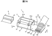
- FIG. 1A is a perspective view showing a cable with a terminal according to the first embodiment of the present invention.
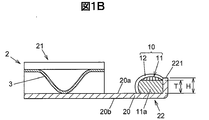
- 1B is a cross-sectional view taken along line AA in FIG. 1A.
- This terminal-attached cable is used, for example, to supply a current to an electric motor that generates a driving force for running the vehicle.
- the cable with terminal 1 includes a cable 10 having a conductor portion 11 formed by a plurality of strands 110 and a covering portion 12 made of an insulator covering the conductor portion 11, and a terminal connected to the conductor portion 11 of the cable 10. 2 are provided.
- the conductor portion 11 of the cable 10 is exposed from the covering portion 12 at the end portion on the terminal 2 side, and the exposed portion is connected to the terminal 2 by ultrasonic welding.
- the terminal 2 is a female terminal, and a counterpart terminal 4 that is a male terminal is connected to the terminal 2.
- the mating terminal 4 is a connection target of the terminal 2 and is an aspect of the mating member in the present invention. However, this male-female relationship may be reversed.
- the terminal 2 is formed by bending a single plate-like metal conductor obtained by punching a material made of a conductive metal plate into a predetermined shape.
- the terminal 2 has a fitting portion 21 that is electrically connected to the counterpart terminal 4 by fitting with the counterpart terminal 4, and a cable connection portion 22 to which the conductor portion 11 of the cable 10 is connected by ultrasonic welding. Is integrated.
- the fitting portion 21 is formed in a cylindrical shape into which the connection portion 41 of the mating terminal 4 is fitted, and the spring member 3 that elastically contacts the connection portion 41 of the mating terminal 4 is accommodated therein.
- the spring member 3 has four engagement protrusions 31 (only two engagement protrusions 31 are shown in FIG. 1), and these engagement protrusions 31 are formed in four fitting windows 21.
- the portions 21a are respectively engaged and fixed.
- the fitting portion 21 and the cable connecting portion 22 are arranged along the fitting direction with the counterpart terminal 4. More specifically, the terminal 2 has a flat rectangular flat plate portion 20, a cylindrical fitting portion 21 is formed at one end portion in the long side direction, and the other end portion becomes a cable connection portion 22. ing. Assuming that the surface of the flat plate portion 20 on the side shown in FIG. 1 is the upper surface 20 a and the opposite surface is the lower surface 20 b, the upper surface 20 a of the flat plate portion 20 in the fitting portion 21 faces the spring member 3 and the cable connection portion 22. The conductor portion 11 of the cable 10 is welded to the upper surface 20a of the flat plate portion 20 in FIG.
- the cable 10 extends in a direction orthogonal to the fitting direction of the terminal 2 with the mating terminal 4 at the cable connection portion 22 of the terminal 2.
- this fitting direction is indicated by an arrow X
- the extending direction of the cable 10 at the cable connecting portion 22 is indicated by an arrow Y.
- the arrow X direction corresponds to the long side direction of the flat plate portion 20
- the arrow Y direction corresponds to the short side direction of the flat plate portion 20.
- the long side direction of the flat plate portion 20 may be referred to as the longitudinal direction of the terminal 2
- the short side direction of the flat plate portion 20 may be referred to as the short direction of the terminal 2.
- the movement of the plurality of strands 110 in the direction away from the fitting portion 21 in the welding process to be described later is restricted at the end opposite to the fitting portion 21 in the longitudinal direction of the terminal 2.
- a regulating protrusion 221 is provided.
- the restricting protrusion 221 is formed by bending a plate-like metal conductor serving as the terminal 2 at the end opposite to the fitting portion 21.
- the regulation protrusion 221 is bent at a right angle toward the upper surface 20 a side of the flat plate portion 20.
- the height H of the restricting protrusion 221 in the direction perpendicular to the upper surface 20a of the flat plate portion 20 is formed to be higher than the thickness T of the conductor portion 11 in the ultrasonic welded portion.
- the conductor portion 11 of the cable 10 is welded to the cable connection portion 22 of the terminal 2 at the welded portion 11a.
- this welded part 11a by receiving ultrasonic vibration from an ultrasonic horn 53 of the ultrasonic connecting device 5 described later, the plurality of strands 110 are melted and welded to the upper surface 20a of the flat plate part 20 in the cable connecting part 22. ing.
- FIG. 2 is a schematic diagram showing an ultrasonic connection device 5 for ultrasonic welding of the conductor portion 11 of the cable 10 to the cable connection portion 22 of the terminal 2.
- the ultrasonic connection device 5 includes an ultrasonic oscillator 50 and a main body 51 connected to the ultrasonic oscillator 50.
- the main body 51 includes an anvil 52 on which the terminal 2 is placed, an ultrasonic horn 53 having a horn chip 531 at its tip, a horn support 54 that supports the ultrasonic horn 53, an anvil 52, and a horn support 54. And a base 55 for fixing the frame.
- the ultrasonic horn 53 can be moved in the vertical direction (arrow Z direction) by a drive mechanism (not shown) provided in the horn support 54.
- the base end portion of the ultrasonic horn 53 is supported in the horn support portion 54, and an ultrasonic coil connected to the ultrasonic oscillator 50 is provided at the base end portion.
- an ultrasonic signal from the ultrasonic oscillator 50 is supplied to the ultrasonic coil, the ultrasonic horn 53 is excited.
- the ultrasonic vibration of the ultrasonic horn 53 is transmitted to the conductor portion 11 of the cable 10 via the horn chip 531, and the element wire 110 of the conductor portion 11 in the portion in contact with the horn chip 531 is vibrated.
- the manufacturing method of the cable 1 with a terminal includes a disposing step of disposing the terminal 2 and the conductor portion 11 at the tip of the cable 10 between the anvil 52 of the ultrasonic connecting device 5 and the horn chip 531 of the ultrasonic horn 53, The ultrasonic horn 53 is ultrasonically vibrated in a state where the chip 531 is pressed against the conductor portion 11 of the cable 10, and the welding step is performed to weld the conductor portion 11 of the cable 10 to the cable connecting portion 22 of the terminal 2.
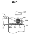
- FIG. 3A and 3B are explanatory diagrams showing the terminal 2 arranged on the anvil 52 in the arranging step and the conductor part 11 of the cable 10 arranged on the upper surface 20a side of the flat plate part 20 in the cable connecting part 22 of the terminal 2.
- FIG. 3A shows a state in which a part of the terminal 2 and the conductor portion 11 is broken and viewed from the short direction of the terminal 2.
- FIG. 3B shows a state in which the terminal 2 and the cable 10 are viewed from the regulation protrusion 221 side along the longitudinal direction of the terminal 2.
- inner side (fitting part 21 side) of the control protrusion 221 is shown with the broken line.
- the conductor part 11 of the cable 10 is arranged so as to be in contact with the upper surface 20a of the flat plate part 20 in the cable connecting part 22 of the terminal 2.
- the cable 10 is supported by a support member (not shown) so that the conductor portion 11 exposed from the covering portion 12 extends in the short direction of the terminal 2.
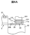
- FIGS. 3A and 3B are explanatory views showing a state in which the terminal 2 and the cable 10 in the welding process are viewed from the same direction as FIGS. 3A and 3B.
- the horn chip 531 presses the conductor portion 11 of the cable 10 against the cable connection portion 22 of the terminal 2 by moving the ultrasonic horn 53 downward.
- the ultrasonic horn 53 vibrates ultrasonically to vibrate a plurality of strands 110 of the conductor portion 11, thereby removing oxide films on the metal surface of the conductor portion 11 and the cable connection portion 22 and impurities on the surface layer. Scattered and clean activated metal molecules appear on the joint surface.
- a solid-phase welding state is created using attractive force between metal atoms, and the conductor portion 11 and the connection portion 22 are welded.
- the movement of the wire 110 in the direction away from the fitting portion 21 due to the pressing force of the ultrasonic horn 53 is restricted by the restriction protrusion 221 of the terminal 2. That is, when the conductor portion 11 of the cable 10 is ultrasonically welded to the cable connection portion 22, the conductor is connected by the ultrasonic horn 53 while the movement in the direction away from the fitting portion 21 of the element wire 110 is restricted by the restriction protrusion 221. The part 11 is vibrated.
- FIG. 5 is a perspective view showing a terminal-equipped cable 1 ′ according to a comparative example.
- the conductor portion 11 at the end of the cable 10 is ultrasonically welded to the terminal 2 ′ similarly to the terminal-attached cable 1 according to the first embodiment.
- the same components as those described in the first embodiment are denoted by the same reference numerals as those in FIG.
- FIG. 6A is a perspective view showing a terminal-attached cable 1A according to the present embodiment.
- 6B is a front view of the terminal 2 of the cable with terminal 1A as viewed from the upper surface 20a side of the flat plate portion 20.
- FIG. 6C is a side view of the terminal 2 of the cable with terminal 1A as viewed from the regulation protrusion 221 side along the longitudinal direction.
- 6A to 6C the same components as those described in the first embodiment are denoted by the same reference numerals as those in FIG. 1, and redundant descriptions are omitted.
- the restricting protrusion 221 of the terminal 2 is formed by cutting and raising the plate-shaped metal conductor serving as the terminal 2 at the end opposite to the fitting portion 21.
- the cut-and-raised portion is a portion corresponding to the outer side (opposite to the fitting portion 21) of the slit 2a in the longitudinal direction of the terminal 2 provided with a slit-like cut 2a along the short direction of the terminal 2 on the metal conductor. Is bent and protruded toward the upper surface 20 a of the flat plate portion 20.
- the regulation protrusion 221 is formed at one end portion in the short direction of the terminal 2 corresponding to the distal end side of the wire 110 exposed from the covering portion 12 of the cable 10.
- the cut 2a is formed from the end portion in the short side direction of the flat plate portion 20 corresponding to the tip end side of the strand 110 toward the end portion on the opposite side (the covering portion 12 side), and the cut length L is The width of the flat plate portion 20 in the short direction of the terminal 2 is shorter.
- the height H of the restricting protrusion 221 in the direction perpendicular to the upper surface 20a of the flat plate portion 20 is the conductor portion of the ultrasonic welded portion. 11 and higher than the thickness T (see FIG. 1B).
- the same effect as that of the first embodiment can be obtained.
- the formation of the cut 2a and the process of bending the portion corresponding to the outside of the cut 2a can be performed simultaneously by one press work, the regulation protrusion 221 can be easily formed.
- FIG. 7A is a perspective view showing a terminal-equipped cable 1B according to the present embodiment.
- FIG. 7B is a front view of the terminal 2 of the cable with terminal 1 ⁇ / b> B as viewed from the upper surface 20 a side of the flat plate portion 20.
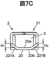
- FIG. 7C is a side view of the terminal 2 of the cable with terminal 1 ⁇ / b> B as viewed from the regulation protrusion 221 side along the longitudinal direction of the terminal 2.
- 7A to 7C the same components as those described in the first embodiment are denoted by the same reference numerals as those in FIG. 1, and redundant descriptions are omitted.
- the terminal 2 is formed with a first restricting protrusion 221A and a second restricting protrusion 221B.
- the first restricting protrusions 221A and the second restricting protrusions 221B are formed by cutting and raising a plate-like metal conductor serving as the terminal 2 at the end opposite to the fitting portion 21.
- the flat plate portion 20 of the terminal 2 is formed with a slit-like first cut 2b and a second cut 2c for cutting and raising.
- the first restricting protrusion 221A is formed at the end of the plurality of strands 110 in the cable connecting portion 22 in the extending direction of the cable 10, and the second restricting protrusion 221B is at the opposite end. Is formed.
- a pair of restricting protrusions (first restricting protrusion 221 ⁇ / b> A and second restricting protrusion 221 ⁇ / b> B) are formed at both ends of the cable connecting portion 22 in the short direction of the terminal 2.
- the first restricting protrusion 221A bends a portion corresponding to the outside of the slit-like first notch 2b (on the opposite side to the fitting portion 21 in the longitudinal direction of the terminal 2) and protrudes toward the upper surface 20a side of the flat plate portion 20.
- the second restricting protrusion 221B is formed by bending the portion corresponding to the outer side (opposite to the fitting portion 21 in the longitudinal direction of the terminal 2) from the slit-like second notch 2c. It is formed by projecting to the upper surface 20a side.
- the first cut 2b is formed from an end portion in the short side direction of the flat plate portion 20 corresponding to the tip side of the strand 110 exposed from the covering portion 12 toward an end portion on the opposite side (the covering portion 12 side).
- the second notch 2b is formed from the end portion in the short side direction of the flat plate portion 20 corresponding to the base side of the strand 110 exposed from the covering portion 12 toward the end portion on the opposite side (the tip end side of the strand 110).
- the conductor portion 11 of the cable 10 is ultrasonically welded to the cable connecting portion 22, the first and second regulating protrusions 221A. , 221 ⁇ / b> B, the conductor portion 11 is vibrated by the ultrasonic horn 53 in a state where the movement of the element wire 110 in the direction away from the fitting portion 21 is restricted.
- the same effect as in the first and second embodiments can be obtained. Further, since the first restricting protrusion 221A and the second restricting protrusion 221B are formed on the cable connecting portion 22 of the terminal 2, the opposite side to the fitting portion 21 of the strand 110 due to the pressing force of the ultrasonic horn 53 Is restricted at both ends of the terminal 2 in the short direction, and the generation of the stray line can be more reliably suppressed as compared with the second embodiment.
- the fitting part (21) electrically connected to the mating member (4) by fitting with the mating member (4) and the conductor part (11) of the cable (10) are connected by ultrasonic welding.
- the regulation protrusion (221) is formed by cutting and raising a plate-like metal conductor at an end opposite to the fitting portion (21). Cable (1A).
- the fitting part (21) electrically connected to the mating member (4) by fitting with the mating member (4) and the conductor part (11) of the cable (10) are connected by ultrasonic welding.
- a terminal-equipped cable (1, 1A, 1B) comprising a terminal (2) having a cable connection portion (22), wherein the cable (10) is connected to the cable connection portion (22).
- the terminal (2) extends in a direction (Y) perpendicular to the fitting direction (X) with the mating member (4), and the cable connecting portion (22) has the fitting portion (21).
Landscapes
- Engineering & Computer Science (AREA)
- Manufacturing & Machinery (AREA)
- Manufacturing Of Electrical Connectors (AREA)
- Connections Effected By Soldering, Adhesion, Or Permanent Deformation (AREA)
Abstract
相手側端子(4)との嵌合方向に対して直交する方向にケーブル(10)を延在させ、かつケーブル(10)の導体部(11)を端子(2)に超音波溶接によって接続しながらも、逸れ線の発生を抑制することを課題とする。端子付きケーブル(1)は、複数の素線(110)からなる導体部(11)及び被覆部(12)を有するケーブル(10)と、相手側端子(4)と接続される嵌合部(21)及びケーブル(10)の導体部(11)が超音波溶接によって接続されるケーブル接続部(22)を有する端子(2)とを備える。ケーブル(10)は、ケーブル接続部(22)において前記嵌合方向に対して直交する方向に延在し、ケーブル接続部(22)には、嵌合部(21)とは反対側の端部に、超音波ホーン(53)の押し付け力による素線(110)の嵌合部(21)から離間する方向への移動を規制する規制突起(221)が設けられる。
Description
本発明は、端部に端子が接続された端子付きケーブル、及び端子付きケーブルの製造方法に関する。
従来、例えば車両の走行用の駆動力を発生する電気モータに電流を供給するための端子付きケーブルとして、特許文献1に記載のものが知られている。また、このような端子付きケーブルを複数本備えたワイヤハーネスとして、特許文献2に記載のものが知られている。
特許文献1に記載の端子付きケーブルは、複数の素線からなる導体部が超音波溶接によって端子に接続されている。この超音波溶接は、超音波接続装置の超音波ホーンとアンビルとの間に端子の板状基部とケーブルの導体部とを挟み、超音波ホーンからの超音波振動を導体部に付与することで行われる。この端子付きケーブルでは、ケーブルの導体部と端子とが溶接によって接続されるので、大きな電流を流しても、この接続部における電気抵抗を小さくすることができる。
一方、特許文献2に記載のワイヤハーネスのコネクタでは、相手側端子(オス端子)との嵌合方向が、コネクタからのケーブル(電線)の引き出し方向に対して直交している。このため、コネクタに内蔵された端子(メス端子)は、相手側端子との接続部の中心軸線とケーブルに接続される電線接続部の中心軸線とが直交するように折り曲げられ、ケーブルの導体部が電線接続部に加締めによって接続されている。このワイヤハーネスによれば、相手側端子との嵌合方向におけるコネクタの厚みを薄くすることができ、車両への搭載性を向上させることができる。
特許文献2に記載のワイヤハーネスでは、相手側端子との接続部の中心軸線と電線接続部の中心軸線とが直交するように端子を折り曲げる必要となるので、端子の製造工程が複雑化してしまう。そこで、本願の発明者らは、端子の製造を容易としながらも相手側端子との嵌合方向に対して直交する方向にケーブルを延在させることが出来るように、端子の一端部において、相手側端子との嵌合方向に対して直交する方向にケーブルの導体部を超音波溶接によって接続することを考えた。
しかし、ケーブルの導体部が複数の素線からなる場合に、この導体部に超音波ホーンを押し付けると、その押し付け力によって一部の素線が相手部材との接続部から離間する方向に移動してしまい、この一部の素線に超音波ホーンからの超音波振動が付与されなくなる場合があった。このような素線は、逸れ線(はぐれせん)となって溶接された素線の束から遊離し、例えばコネクタ内における絶縁性に影響を与えてしまうおそれがある。
そこで、本発明は、相手部材との嵌合方向に対して直交する方向にケーブルを延在させ、かつケーブルの導体部を端子に超音波溶接によって接続しながらも、絶縁性に影響を与えるおそれのある逸れ線の発生を抑制することが可能な端子付きケーブル、及びその製造方法を提供することを目的とする。
本発明は、上記課題を解決することを目的として、複数の素線により形成された導体部、及び前記導体部を被覆する絶縁体からなる被覆部を有するケーブルと、接続対象となる相手部材との嵌合によって前記相手部材と電気的に接続される嵌合部、及び前記ケーブルの前記導体部が超音波溶接によって接続されるケーブル接続部を有する端子とを備え、前記ケーブルは、前記ケーブル接続部において前記端子の前記相手部材との嵌合方向に対して直交する方向に延在し、前記ケーブル接続部には、前記嵌合部とは反対側の端部に、超音波ホーンの押し付け力による前記素線の前記嵌合部から離間する方向への移動を規制する規制突起が設けられている、端子付きケーブルを提供する。
また、本発明は、上記課題を解決することを目的として、複数の素線により形成された導体部、及び前記導体部を被覆する絶縁体からなる被覆部を有するケーブルと、接続対象となる相手部材との嵌合により前記相手部材と電気的に接続される嵌合部、及び前記ケーブルの前記導体部が超音波溶接によって接続されるケーブル接続部を有する端子とを備えた端子付きケーブルの製造方法であって、前記ケーブルは、前記ケーブル接続部において前記端子の前記相手部材との嵌合方向に対して直交する方向に延在し、前記ケーブル接続部には、前記嵌合部とは反対側の端部に、超音波ホーンの押し付け力による前記素線の前記嵌合部から離間する方向の移動を規制する規制突起が設けられ、前記ケーブルの前記導体部を前記ケーブル接続部に超音波溶接する際、前記規制突起によって前記素線の前記嵌合部から離間する方向の移動を規制した状態で前記超音波ホーンによって前記導体部を加振する、端子付きケーブルの製造方法を提供する。
本発明に係る端子付きケーブル、及び端子付きケーブルの製造方法によれば、相手部材との嵌合方向に対して直交する方向にケーブルを延在させ、かつケーブルの導体部を端子に超音波溶接によって接続しながらも、絶縁性に影響を与えるおそれのある逸れ線の発生を抑制することが可能となる。
[第1の実施の形態]
図1Aは、本発明の第1の実施の形態に係る端子付きケーブルを示す斜視図である。図1Bは、図1AのA-A線断面図である。この端子付きケーブルは、例えば車両の走行用の駆動力を発生する電気モータに電流を供給するために用いられる。
図1Aは、本発明の第1の実施の形態に係る端子付きケーブルを示す斜視図である。図1Bは、図1AのA-A線断面図である。この端子付きケーブルは、例えば車両の走行用の駆動力を発生する電気モータに電流を供給するために用いられる。
(端子付きケーブルの構成)
端子付きケーブル1は、複数の素線110により形成された導体部11、及び導体部11を被覆する絶縁体からなる被覆部12を有するケーブル10と、ケーブル10の導体部11に接続された端子2とを備えている。ケーブル10の導体部11は、端子2側の端部において被覆部12から露出し、この露出した部分が端子2に超音波溶接によって接続されている。
端子付きケーブル1は、複数の素線110により形成された導体部11、及び導体部11を被覆する絶縁体からなる被覆部12を有するケーブル10と、ケーブル10の導体部11に接続された端子2とを備えている。ケーブル10の導体部11は、端子2側の端部において被覆部12から露出し、この露出した部分が端子2に超音波溶接によって接続されている。
本実施の形態では、端子2がメス端子であり、この端子2にオス端子である相手側端子4が接続される。この相手側端子4は、端子2の接続対象であり、本発明における相手部材の一態様である。ただし、この雄雌関係は逆であってもよい。
端子2は、導電性の金属板からなる素材を所定の形状に打ち抜いて得られた一枚の板状の金属導体を屈曲して形成されている。また、端子2は、相手側端子4との嵌合によって相手側端子4と電気的に接続される嵌合部21、及びケーブル10の導体部11が超音波溶接によって接続されるケーブル接続部22を一体に有している。嵌合部21は、相手側端子4の接続部41が嵌入する筒状に形成され、その内部には相手側端子4の接続部41に弾性的に接触するバネ部材3が収容されている。このバネ部材3は、4つの係合突起31(図1には、2つの係合突起31のみを示す)を有し、これらの係合突起31が嵌合部21に形成された4つの窓部21aにそれぞれ係合して固定されている。
端子2において、嵌合部21とケーブル接続部22とは、相手側端子4との嵌合方向に沿って並んでいる。より具体的には、端子2は平坦な長方形状の平板部20を有し、この長辺方向の一端部に筒状の嵌合部21が形成され、他端部がケーブル接続部22となっている。図1に示す側の平板部20の面を上面20aとし、その反対側の面を下面20bとすると、嵌合部21における平板部20の上面20aはバネ部材3と対向し、ケーブル接続部22における平板部20の上面20aにはケーブル10の導体部11が溶着される。
ケーブル10は、端子2のケーブル接続部22において、端子2の相手側端子4との嵌合方向に対して直交する方向に延在している。図1では、この嵌合方向を矢印Xで示し、ケーブル接続部22におけるケーブル10の延在方向を矢印Yで示している。矢印X方向は平板部20の長辺方向にあたり、矢印Y方向は平板部20の短辺方向にあたる。なお、以下の説明では、平板部20の長辺方向を端子2の長手方向といい、平板部20の短辺方向を端子2の短手方向ということがある。
ケーブル接続部22には、端子2の長手方向における嵌合部21とは反対側の端部に、後述する溶接工程において嵌合部21から離間する方向への複数の素線110の移動を規制する規制突起221が設けられている。この規制突起221は、端子2となる板状の金属導体を嵌合部21とは反対側の端部で折り曲げることにより形成されている。本実施の形態では、規制突起221が平板部20の上面20a側に直角に折り曲げられている。平板部20の上面20aに対して垂直な方向の規制突起221の高さHは、超音波溶接された部分の導体部11の厚みTよりも高く形成されている。
ケーブル10の導体部11は、溶接部11aにおいて端子2のケーブル接続部22に溶着している。この溶接部11aでは、後述する超音波接続装置5の超音波ホーン53から超音波振動を受けることにより、複数の素線110同士が溶け合い、ケーブル接続部22における平板部20の上面20aに溶着している。
(超音波接続装置の構成)
図2は、ケーブル10の導体部11を端子2のケーブル接続部22に超音波溶接するための超音波接続装置5を示す概略図である。
図2は、ケーブル10の導体部11を端子2のケーブル接続部22に超音波溶接するための超音波接続装置5を示す概略図である。
図2に示すように、本実施の形態に係る超音波接続装置5は、超音波発振器50と、超音波発振器50に接続される本体部51とを備えて構成されている。本体部51は、端子2が載置されるアンビル52と、ホーンチップ531を先端部に有する超音波ホーン53と、超音波ホーン53を支持するホーン支持部54と、アンビル52及びホーン支持部54を固定する基台55とを備えて構成されている。超音波ホーン53は、ホーン支持部54に設けられた図示しない駆動機構によって、上下方向(矢印Z方向)に移動可能である。
超音波ホーン53の基端部はホーン支持部54内で支持され、この基端部には、超音波発振器50に接続された超音波コイルが設けられている。この超音波コイルに超音波発振器50からの超音波信号が供給されると、超音波ホーン53が励振される。超音波ホーン53の超音波振動は、ホーンチップ531を介してケーブル10の導体部11に伝達され、ホーンチップ531に接する部分における導体部11の素線110が加振される。
(端子付きケーブルの製造方法)
次に、図3A,図3B,図4A,及び図4Bを参照して、端子付きケーブル1の製造方法について説明する。端子付きケーブル1の製造方法は、超音波接続装置5のアンビル52と超音波ホーン53のホーンチップ531との間に端子2及びケーブル10の先端部における導体部11を配置する配置工程と、ホーンチップ531をケーブル10の導体部11に押し付けた状態で超音波ホーン53を超音波振動させ、ケーブル10の導体部11を端子2のケーブル接続部22に溶接する溶接工程とを有している。
次に、図3A,図3B,図4A,及び図4Bを参照して、端子付きケーブル1の製造方法について説明する。端子付きケーブル1の製造方法は、超音波接続装置5のアンビル52と超音波ホーン53のホーンチップ531との間に端子2及びケーブル10の先端部における導体部11を配置する配置工程と、ホーンチップ531をケーブル10の導体部11に押し付けた状態で超音波ホーン53を超音波振動させ、ケーブル10の導体部11を端子2のケーブル接続部22に溶接する溶接工程とを有している。
図3A及び図3Bは、配置工程においてアンビル52上に配置された端子2、及び端子2のケーブル接続部22における平板部20の上面20a側に配置されたケーブル10の導体部11を示す説明図である。図3Aは、端子2及び導体部11の一部を破断して、端子2の短手方向から見た状態を示している。図3Bは、端子2及びケーブル10を、端子2の長手方向に沿って規制突起221側から見た状態を示している。図3Bでは、規制突起221の奥側(嵌合部21側)における導体部11の素線110を破線で示している。
配置工程において、ケーブル10の導体部11は、端子2のケーブル接続部22における平板部20の上面20aに接するように配置される。ケーブル10は、図示しない支持部材によって、被覆部12から露出した導体部11が端子2の短手方向に延在するように支持される。
図4A及び図4Bは、溶接工程における端子2及びケーブル10を図3A及び図3Bと同方向から見た状態を示す説明図である。
溶接工程では、超音波ホーン53の下方への移動によって、ホーンチップ531がケーブル10の導体部11を端子2のケーブル接続部22に押し付ける。そして、この状態で超音波ホーン53が超音波振動することにより導体部11の複数の素線110が加振され、導体部11及びケーブル接続部22の金属表面の酸化被膜や表面層の不純物を飛散させ、接合面に清浄な活性化した金属分子が現れる。更に超音波振動を与えることで、金属原子間の引力を利用して固相溶接状態を作り出し、導体部11と接続部22が溶接される。
この溶接工程では、超音波ホーン53の押し付け力による素線110の嵌合部21から離間する方向への移動が、端子2の規制突起221によって規制される。すなわち、ケーブル10の導体部11をケーブル接続部22に超音波溶接する際、規制突起221によって素線110の嵌合部21から離間する方向の移動を規制した状態で、超音波ホーン53によって導体部11を加振する。
これにより、複数の素線110のうちの一部の素線110が逸れ線となって嵌合部21とは反対側に突き出てしまうことを防ぐことができ、端子付きケーブル1の絶縁性が確保される。なお、嵌合部21側に突き出る逸れ線が発生したとしても、このような逸れ線は、端子2の周辺におけるコネクタハウジング等の導電性部材に接触しないので、端子付きケーブル1の絶縁性に影響しない。
(比較例)
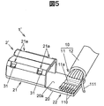
図5は、比較例に係る端子付きケーブル1´を示す斜視図である。この端子付きケーブル1´は、第1の実施の形態に係る端子付きケーブル1と同様に、端子2´にケーブル10の端部における導体部11が超音波溶接されているが、この端子2´には、第1の実施の形態に係る端子2の規制突起221が設けられていない。図5において、上記第1の実施の形態において説明したものと共通する構成要素については、図1と同一の符号を付して重複した説明を省略する。
図5は、比較例に係る端子付きケーブル1´を示す斜視図である。この端子付きケーブル1´は、第1の実施の形態に係る端子付きケーブル1と同様に、端子2´にケーブル10の端部における導体部11が超音波溶接されているが、この端子2´には、第1の実施の形態に係る端子2の規制突起221が設けられていない。図5において、上記第1の実施の形態において説明したものと共通する構成要素については、図1と同一の符号を付して重複した説明を省略する。
このような端子2´に対して上記と同様の方法によりケーブル10の導体部11を超音波溶接すると、超音波ホーン53の押し付け力によって複数の素線110のうちの一部が素線110の束から外れ、嵌合部21側とは反対側に突出する逸れ線となる場合がある。図5では、逸れ線となった素線110を符号111で示している。このような逸れ線111は、超音波ホーン53が超音波振動しても加振されないので、端子2´に溶着されず、例えば車両の走行中の振動を受けると、その先端部が大きく振れてしまう。そして、この逸れ線111の振れによって絶縁性が損なわれてしまうおそれがある。
(第1の実施の形態の効果)
以上説明した第1の実施の形態によれば、溶接工程における超音波ホーン53の押し付け力による素線110の嵌合部21とは反対側への移動が規制突起221によって規制されるので、比較例について図5を参照して説明した逸れ線111の発生が抑制される。これにより、端子付きケーブル1の絶縁性が確保される。また、規制突起221は、端子2となる板状の金属導体を嵌合部21とは反対側の端部で折り曲げることにより形成されるので、その形成が容易である。
以上説明した第1の実施の形態によれば、溶接工程における超音波ホーン53の押し付け力による素線110の嵌合部21とは反対側への移動が規制突起221によって規制されるので、比較例について図5を参照して説明した逸れ線111の発生が抑制される。これにより、端子付きケーブル1の絶縁性が確保される。また、規制突起221は、端子2となる板状の金属導体を嵌合部21とは反対側の端部で折り曲げることにより形成されるので、その形成が容易である。
[第2の実施の形態]
次に、本発明の第2の実施の形態について図6A~図6Cを参照して説明する。
次に、本発明の第2の実施の形態について図6A~図6Cを参照して説明する。
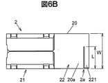
図6Aは、本実施の形態に係る端子付きケーブル1Aを示す斜視図である。図6Bは、端子付きケーブル1Aの端子2を平板部20の上面20a側から見た正面図である。図6Cは、端子付きケーブル1Aの端子2をその長手方向に沿って規制突起221側から見た側面図である。図6A~図6Cにおいて、第1の実施の形態において説明したものと共通する構成要素については、図1と同一の符号を付して重複した説明を省略する。
本実施の形態では、端子2の規制突起221が、端子2となる板状の金属導体を嵌合部21とは反対側の端部で切り起こすことにより形成されている。ここで、切り起こしとは、金属導体に端子2の短手方向に沿うスリット状の切れ込み2aを設け、端子2の長手方向における切れ込み2aよりも外側(嵌合部21とは反対側)にあたる部分を屈曲して平板部20の上面20a側に突出させることをいう。
本実施の形態では、規制突起221が、ケーブル10の被覆部12から露出した素線110の先端側にあたる端子2の短手方向の一端部に形成されている。このため、切れ込み2aは、素線110の先端側にあたる平板部20の短辺方向の端部から、その反対側(被覆部12側)の端部に向かって形成され、その切れ込み長さLは、端子2の短手方向における平板部20の幅Wよりも短い。
また、本実施の形態においても、第1の実施の形態と同様に、平板部20の上面20aに対して垂直な方向の規制突起221の高さHが、超音波溶接された部分の導体部11の厚みT(図1B参照)よりも高く形成されている。
この端子付きケーブル1Aの溶接工程では、第1の実施の形態と同様に、ケーブル10の導体部11をケーブル接続部22に超音波溶接する際、規制突起221によって素線110の嵌合部21から離間する方向の移動を規制した状態で、超音波ホーン53によって導体部11を加振する。
本実施の形態によっても、第1の実施の形態と同様の効果が得られる。また、切れ込み2aの形成と、切れ込み2aよりも外側にあたる部分を屈曲させる加工とは、1回のプレス加工によって同時に行うことができるので、規制突起221を容易に形成することができる。
[第3の実施の形態]
次に、本発明の第3の実施の形態について図7A~図7Cを参照して説明する。
次に、本発明の第3の実施の形態について図7A~図7Cを参照して説明する。
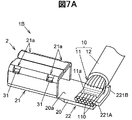
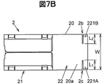
図7Aは、本実施の形態に係る端子付きケーブル1Bを示す斜視図である。図7Bは、端子付きケーブル1Bの端子2を平板部20の上面20a側から見た正面図である。図7Cは、端子付きケーブル1Bの端子2を端子2の長手方向に沿って規制突起221側から見た側面図である。図7A~図7Cにおいて、第1の実施の形態において説明したものと共通する構成要素については、図1と同一の符号を付して重複した説明を省略する。
本実施の形態では、端子2に第1の規制突起221A及び第2の規制突起221Bが形成されている。これら第1の規制突起221A及び第2の規制突起221Bは、端子2となる板状の金属導体を嵌合部21とは反対側の端部で切り起こすことにより形成されている。端子2の平板部20には、この切り起こしのためのスリット状の第1の切れ込み2b及び第2の切れ込み2cが形成されている。第1の規制突起221Aは、ケーブル接続部22におけるケーブル10の延在方向の複数の素線110の先端側の端部に形成され、第2の規制突起221Bは、その反対側の端部に形成されている。すなわち、本実施の形態では、一対の規制突起(第1の規制突起221A及び第2の規制突起221B)が、端子2の短手方向におけるケーブル接続部22の両端部に形成されている。
第1の規制突起221Aは、スリット状の第1の切れ込み2bよりも外側(端子2の長手方向における嵌合部21とは反対側)にあたる部分を屈曲して平板部20の上面20a側に突出させることにより形成され、第2の規制突起221Bは、スリット状の第2の切れ込み2cよりも外側(端子2の長手方向における嵌合部21とは反対側)にあたる部分を屈曲して平板部20の上面20a側に突出させることにより形成されている。第1の切れ込み2bは、被覆部12から露出した素線110の先端側にあたる平板部20の短辺方向の端部から、その反対側(被覆部12側)の端部に向かって形成され、第2の切れ込み2bは、被覆部12から露出した素線110の根元側にあたる平板部20の短辺方向の端部から、その反対側(素線110の先端側)の端部に向かって形成されている。
第1の切れ込み2bの切れ込み長さL1と第2の切れ込み2cの切れ込み長さL2とは同等であり、切れ込み長さL1と切れ込み長さL2との和(=L1+L2)は、端子2の短手方向における平板部20の幅Wよりも短い。また、平板部20の上面20aに対して垂直な方向の第1の規制突起221Aの高さH1及び第2の規制突起221Bの高さH2は、超音波溶接された部分の導体部11の厚みT(図1B参照)よりも高く形成されている。
この端子付きケーブル1Bの溶接工程では、第1及び第2の実施の形態と同様に、ケーブル10の導体部11をケーブル接続部22に超音波溶接する際、第1及び第2の規制突起221A,221Bによって素線110の嵌合部21から離間する方向の移動を規制した状態で、超音波ホーン53によって導体部11を加振する。
本実施の形態によっても、第1及び第2の実施の形態と同様の効果が得られる。また、端子2のケーブル接続部22に第1の規制突起221A及び第2の規制突起221Bが形成されているので、超音波ホーン53の押し付け力による素線110の嵌合部21とは反対側への移動が端子2の短手方向の両端部で規制され、第2の実施の形態に比較してより確実に逸れ線の発生を抑制することができる。
(実施の形態のまとめ)
次に、以上説明した実施の形態から把握される技術思想について、実施の形態における符号等を援用して記載する。ただし、以下の記載における各符号は、特許請求の範囲における構成要素を実施の形態に具体的に示した部材等に限定するものではない。
次に、以上説明した実施の形態から把握される技術思想について、実施の形態における符号等を援用して記載する。ただし、以下の記載における各符号は、特許請求の範囲における構成要素を実施の形態に具体的に示した部材等に限定するものではない。
[1]複数の素線(110)により形成された導体部(11)、及び前記導体部(11)を被覆する絶縁体からなる被覆部(12)を有するケーブル(10)と、接続対象となる相手部材(4)との嵌合によって前記相手部材(4)と電気的に接続される嵌合部(21)、及び前記ケーブル(10)の前記導体部(11)が超音波溶接によって接続されるケーブル接続部(22)を有する端子(2)とを備え、前記ケーブル(10)は、前記ケーブル接続部(22)において前記端子(2)の前記相手部材(4)との嵌合方向に対して直交する方向に延在し、前記ケーブル接続部(22)には、前記嵌合部(21)とは反対側の端部に、超音波ホーン(53)の押し付け力による前記素線(110)の前記嵌合部(21)から離間する方向への移動を規制する規制突起(221/221A,221B)が設けられている、端子付きケーブル(1,1A,1B)。
[2]前記規制突起(221)は、板状の金属導体を前記嵌合部(21)とは反対側の端部で折り曲げることにより形成されている、前記[1]に記載の端子付きケーブル(1)。
[3]前記規制突起(221)は、板状の金属導体を前記嵌合部(21)とは反対側の端部で切り起こすことにより形成されている、前記[1]に記載の端子付きケーブル(1A)。
[4]前記規制突起(221A,221B)は、前記ケーブル接続部(22)における前記ケーブル(10)の延在方向の両端部に形成されている、前記[3]に記載の端子付きケーブル(1B)。
[5]複数の素線(110)により形成された導体部(21)、及び前記導体部(21)を被覆する絶縁体からなる被覆部(12)を有するケーブル(10)と、接続対象となる相手部材(4)との嵌合により前記相手部材(4)と電気的に接続される嵌合部(21)、及び前記ケーブル(10)の前記導体部(11)が超音波溶接によって接続されるケーブル接続部(22)を有する端子(2)とを備えた端子付きケーブル(1,1A,1B)の製造方法であって、前記ケーブル(10)は、前記ケーブル接続部(22)において前記端子(2)の前記相手部材(4)との嵌合方向(X)に対して直交する方向(Y)に延在し、前記ケーブル接続部(22)には、前記嵌合部(21)とは反対側の端部に、超音波ホーン(53)の押し付け力による前記素線(110)の前記嵌合部(21)から離間する方向の移動を規制する規制突起(221/221A,221B)が設けられ、前記ケーブル(10)の前記導体部(11)を前記ケーブル接続部(22)に超音波溶接する際、前記規制突起(221/221A,221B)によって前記素線(110)の前記嵌合部(21)から離間する方向の移動を規制した状態で前記超音波ホーン(53)によって前記導体部(11)を加振する、端子付きケーブル(1,1A,1B)の製造方法。
以上、本発明の実施の形態を説明したが、上記に記載した実施の形態は特許請求の範囲に係る発明を限定するものではない。また、実施の形態の中で説明した特徴の組合せの全てが発明の課題を解決するための手段に必須であるとは限らない点に留意すべきである。
1,1A,1B…端子付きケーブル
10…ケーブル
11…導体部
110…素線
12…被覆部
2…端子
21…嵌合部
22…ケーブル接続部
221,221A,221B…規制突起
4…相手側端子(相手部材)
53…超音波ホーン
10…ケーブル
11…導体部
110…素線
12…被覆部
2…端子
21…嵌合部
22…ケーブル接続部
221,221A,221B…規制突起
4…相手側端子(相手部材)
53…超音波ホーン
Claims (5)
- 複数の素線により形成された導体部、及び前記導体部を被覆する絶縁体からなる被覆部を有するケーブルと、
接続対象となる相手部材との嵌合によって前記相手部材と電気的に接続される嵌合部、及び前記ケーブルの前記導体部が超音波溶接によって接続されるケーブル接続部を有する端子とを備え、
前記ケーブルは、前記ケーブル接続部において前記端子の前記相手部材との嵌合方向に対して直交する方向に延在し、
前記ケーブル接続部には、前記嵌合部とは反対側の端部に、超音波ホーンの押し付け力による前記素線の前記嵌合部から離間する方向への移動を規制する規制突起が設けられている、
端子付きケーブル。 - 前記規制突起は、板状の金属導体を前記嵌合部とは反対側の端部で折り曲げることにより形成されている、
請求項1に記載の端子付きケーブル。 - 前記規制突起は、板状の金属導体を前記嵌合部とは反対側の端部で切り起こすことにより形成されている、
請求項1に記載の端子付きケーブル。 - 前記規制突起は、前記ケーブル接続部における前記ケーブルの延在方向の両端部に形成されている、
請求項3に記載の端子付きケーブル。 - 複数の素線により形成された導体部、及び前記導体部を被覆する絶縁体からなる被覆部を有するケーブルと、接続対象となる相手部材との嵌合により前記相手部材と電気的に接続される嵌合部、及び前記ケーブルの前記導体部が超音波溶接によって接続されるケーブル接続部を有する端子とを備えた端子付きケーブルの製造方法であって、
前記ケーブルは、前記ケーブル接続部において前記端子の前記相手部材との嵌合方向に対して直交する方向に延在し、
前記ケーブル接続部には、前記嵌合部とは反対側の端部に、超音波ホーンの押し付け力による前記素線の前記嵌合部から離間する方向の移動を規制する規制突起が設けられ、
前記ケーブルの前記導体部を前記ケーブル接続部に超音波溶接する際、前記規制突起によって前記素線の前記嵌合部から離間する方向の移動を規制した状態で前記超音波ホーンによって前記導体部を加振する、
端子付きケーブルの製造方法。
Priority Applications (2)
| Application Number | Priority Date | Filing Date | Title |
|---|---|---|---|
| JP2017505972A JP6481752B2 (ja) | 2015-03-19 | 2015-03-19 | 端子付きケーブル及びその製造方法 |
| PCT/JP2015/058224 WO2016147377A1 (ja) | 2015-03-19 | 2015-03-19 | 端子付きケーブル及びその製造方法 |
Applications Claiming Priority (1)
| Application Number | Priority Date | Filing Date | Title |
|---|---|---|---|
| PCT/JP2015/058224 WO2016147377A1 (ja) | 2015-03-19 | 2015-03-19 | 端子付きケーブル及びその製造方法 |
Publications (1)
| Publication Number | Publication Date |
|---|---|
| WO2016147377A1 true WO2016147377A1 (ja) | 2016-09-22 |
Family
ID=56918507
Family Applications (1)
| Application Number | Title | Priority Date | Filing Date |
|---|---|---|---|
| PCT/JP2015/058224 Ceased WO2016147377A1 (ja) | 2015-03-19 | 2015-03-19 | 端子付きケーブル及びその製造方法 |
Country Status (2)
| Country | Link |
|---|---|
| JP (1) | JP6481752B2 (ja) |
| WO (1) | WO2016147377A1 (ja) |
Cited By (1)
| Publication number | Priority date | Publication date | Assignee | Title |
|---|---|---|---|---|
| JP2023131499A (ja) * | 2022-03-09 | 2023-09-22 | 古河電気工業株式会社 | 端子、端子付き電線及び端子付き電線の製造方法 |
Citations (6)
| Publication number | Priority date | Publication date | Assignee | Title |
|---|---|---|---|---|
| JPH0645258U (ja) * | 1992-11-25 | 1994-06-14 | 株式会社東海理化電機製作所 | ターミナルと電線の接続構造 |
| JPH10149843A (ja) * | 1996-11-19 | 1998-06-02 | Harness Sogo Gijutsu Kenkyusho:Kk | 溶接端子 |
| JPH11219757A (ja) * | 1998-01-30 | 1999-08-10 | Yazaki Corp | シールド電線の端末処理構造及び端末処理方法 |
| JP2004071480A (ja) * | 2002-08-08 | 2004-03-04 | Furukawa Electric Co Ltd:The | 撚線用端子 |
| WO2014109287A1 (ja) * | 2013-01-09 | 2014-07-17 | パナソニック株式会社 | 誘導加熱体および誘導加熱調理器 |
| JP2014222645A (ja) * | 2013-05-14 | 2014-11-27 | 矢崎総業株式会社 | 電線と端子の接合構造及び接合方法 |
Family Cites Families (2)
| Publication number | Priority date | Publication date | Assignee | Title |
|---|---|---|---|---|
| JPS58182369U (ja) * | 1982-05-31 | 1983-12-05 | 松下電工株式会社 | リ−ド線接続装置 |
| JP3097840B2 (ja) * | 1997-09-16 | 2000-10-10 | 矢崎総業株式会社 | レーザによる電気接続部の溶着構造 |
-
2015
- 2015-03-19 JP JP2017505972A patent/JP6481752B2/ja not_active Expired - Fee Related
- 2015-03-19 WO PCT/JP2015/058224 patent/WO2016147377A1/ja not_active Ceased
Patent Citations (6)
| Publication number | Priority date | Publication date | Assignee | Title |
|---|---|---|---|---|
| JPH0645258U (ja) * | 1992-11-25 | 1994-06-14 | 株式会社東海理化電機製作所 | ターミナルと電線の接続構造 |
| JPH10149843A (ja) * | 1996-11-19 | 1998-06-02 | Harness Sogo Gijutsu Kenkyusho:Kk | 溶接端子 |
| JPH11219757A (ja) * | 1998-01-30 | 1999-08-10 | Yazaki Corp | シールド電線の端末処理構造及び端末処理方法 |
| JP2004071480A (ja) * | 2002-08-08 | 2004-03-04 | Furukawa Electric Co Ltd:The | 撚線用端子 |
| WO2014109287A1 (ja) * | 2013-01-09 | 2014-07-17 | パナソニック株式会社 | 誘導加熱体および誘導加熱調理器 |
| JP2014222645A (ja) * | 2013-05-14 | 2014-11-27 | 矢崎総業株式会社 | 電線と端子の接合構造及び接合方法 |
Cited By (1)
| Publication number | Priority date | Publication date | Assignee | Title |
|---|---|---|---|---|
| JP2023131499A (ja) * | 2022-03-09 | 2023-09-22 | 古河電気工業株式会社 | 端子、端子付き電線及び端子付き電線の製造方法 |
Also Published As
| Publication number | Publication date |
|---|---|
| JP6481752B2 (ja) | 2019-03-13 |
| JPWO2016147377A1 (ja) | 2017-12-28 |
Similar Documents
| Publication | Publication Date | Title |
|---|---|---|
| KR101505883B1 (ko) | 전선 접속 방법 | |
| KR101343229B1 (ko) | 전선 말단 처리 방법 | |
| CN107453182B (zh) | 具有端子的电线的制造方法 | |
| JP6813630B2 (ja) | 機器用配線集合体 | |
| JP6598525B2 (ja) | 超音波接合装置及び超音波接合方法 | |
| JP6481752B2 (ja) | 端子付きケーブル及びその製造方法 | |
| JP7648570B2 (ja) | 端子付き電線の接合方法 | |
| JP7022360B2 (ja) | 機器用配線集合体 | |
| JP6719873B2 (ja) | 車両用の機器用配線集合体 | |
| CN113437607A (zh) | 带端子的电线的制造方法以及带端子的电线 | |
| JP7609592B2 (ja) | 端子、ワイヤハーネス、及び、端子付き電線 | |
| JP7140797B2 (ja) | 端子接続構造 | |
| WO2014109287A1 (ja) | 誘導加熱体および誘導加熱調理器 | |
| WO2018012235A1 (ja) | 電気接続アセンブリの製造方法 | |
| WO2018012238A1 (ja) | 電気接続アセンブリの製造方法 | |
| JP2019003869A (ja) | 電線束と端子との接続構造及び接続方法 | |
| CN105449915B (zh) | 电动机及通电压接方法 | |
| JP7389086B2 (ja) | 端子、ワイヤハーネス、及び、端子付き電線 | |
| JP7401569B2 (ja) | 接続端子 | |
| JP2025042118A (ja) | 端子及び端子付き電線 | |
| WO2024062864A1 (ja) | 端子および端子とバスバーとの接続構造 | |
| JP2025040696A (ja) | 端子及び端子付き電線 | |
| JP2022163250A (ja) | 端子付き電線、及び、金属端子 | |
| JP2026032832A (ja) | 端子付き電線 | |
| JP2024012770A (ja) | 端子付電線 |
Legal Events
| Date | Code | Title | Description |
|---|---|---|---|
| 121 | Ep: the epo has been informed by wipo that ep was designated in this application |
Ref document number: 15885473 Country of ref document: EP Kind code of ref document: A1 |
|
| ENP | Entry into the national phase |
Ref document number: 2017505972 Country of ref document: JP Kind code of ref document: A |
|
| NENP | Non-entry into the national phase |
Ref country code: DE |
|
| 122 | Ep: pct application non-entry in european phase |
Ref document number: 15885473 Country of ref document: EP Kind code of ref document: A1 |