WO2016143596A1 - 洗濯乾燥機、洗濯乾燥機の制御装置、乾き度検出装置、及び、乾燥機 - Google Patents
洗濯乾燥機、洗濯乾燥機の制御装置、乾き度検出装置、及び、乾燥機 Download PDFInfo
- Publication number
- WO2016143596A1 WO2016143596A1 PCT/JP2016/056176 JP2016056176W WO2016143596A1 WO 2016143596 A1 WO2016143596 A1 WO 2016143596A1 JP 2016056176 W JP2016056176 W JP 2016056176W WO 2016143596 A1 WO2016143596 A1 WO 2016143596A1
- Authority
- WO
- WIPO (PCT)
- Prior art keywords
- washing
- doppler sensor
- drying
- laundry
- drum
- Prior art date
- Legal status (The legal status is an assumption and is not a legal conclusion. Google has not performed a legal analysis and makes no representation as to the accuracy of the status listed.)
- Ceased
Links
Images




Classifications
-
- D—TEXTILES; PAPER
- D06—TREATMENT OF TEXTILES OR THE LIKE; LAUNDERING; FLEXIBLE MATERIALS NOT OTHERWISE PROVIDED FOR
- D06F—LAUNDERING, DRYING, IRONING, PRESSING OR FOLDING TEXTILE ARTICLES
- D06F58/00—Domestic laundry dryers
- D06F58/32—Control of operations performed in domestic laundry dryers
- D06F58/34—Control of operations performed in domestic laundry dryers characterised by the purpose or target of the control
- D06F58/36—Control of operational steps, e.g. for optimisation or improvement of operational steps depending on the condition of the laundry
- D06F58/38—Control of operational steps, e.g. for optimisation or improvement of operational steps depending on the condition of the laundry of drying, e.g. to achieve the target humidity
-
- D—TEXTILES; PAPER
- D06—TREATMENT OF TEXTILES OR THE LIKE; LAUNDERING; FLEXIBLE MATERIALS NOT OTHERWISE PROVIDED FOR
- D06F—LAUNDERING, DRYING, IRONING, PRESSING OR FOLDING TEXTILE ARTICLES
- D06F25/00—Washing machines with receptacles, e.g. perforated, having a rotary movement, e.g. oscillatory movement, the receptacle serving both for washing and for centrifugally separating water from the laundry and having further drying means, e.g. using hot air
-
- D—TEXTILES; PAPER
- D06—TREATMENT OF TEXTILES OR THE LIKE; LAUNDERING; FLEXIBLE MATERIALS NOT OTHERWISE PROVIDED FOR
- D06F—LAUNDERING, DRYING, IRONING, PRESSING OR FOLDING TEXTILE ARTICLES
- D06F34/00—Details of control systems for washing machines, washer-dryers or laundry dryers
- D06F34/14—Arrangements for detecting or measuring specific parameters
- D06F34/18—Condition of the laundry, e.g. nature or weight
-
- D—TEXTILES; PAPER
- D06—TREATMENT OF TEXTILES OR THE LIKE; LAUNDERING; FLEXIBLE MATERIALS NOT OTHERWISE PROVIDED FOR
- D06F—LAUNDERING, DRYING, IRONING, PRESSING OR FOLDING TEXTILE ARTICLES
- D06F2103/00—Parameters monitored or detected for the control of domestic laundry washing machines, washer-dryers or laundry dryers
- D06F2103/02—Characteristics of laundry or load
- D06F2103/08—Humidity
-
- D—TEXTILES; PAPER
- D06—TREATMENT OF TEXTILES OR THE LIKE; LAUNDERING; FLEXIBLE MATERIALS NOT OTHERWISE PROVIDED FOR
- D06F—LAUNDERING, DRYING, IRONING, PRESSING OR FOLDING TEXTILE ARTICLES
- D06F2103/00—Parameters monitored or detected for the control of domestic laundry washing machines, washer-dryers or laundry dryers
- D06F2103/28—Air properties
- D06F2103/32—Temperature
-
- D—TEXTILES; PAPER
- D06—TREATMENT OF TEXTILES OR THE LIKE; LAUNDERING; FLEXIBLE MATERIALS NOT OTHERWISE PROVIDED FOR
- D06F—LAUNDERING, DRYING, IRONING, PRESSING OR FOLDING TEXTILE ARTICLES
- D06F2103/00—Parameters monitored or detected for the control of domestic laundry washing machines, washer-dryers or laundry dryers
- D06F2103/28—Air properties
- D06F2103/34—Humidity
-
- D—TEXTILES; PAPER
- D06—TREATMENT OF TEXTILES OR THE LIKE; LAUNDERING; FLEXIBLE MATERIALS NOT OTHERWISE PROVIDED FOR
- D06F—LAUNDERING, DRYING, IRONING, PRESSING OR FOLDING TEXTILE ARTICLES
- D06F2105/00—Systems or parameters controlled or affected by the control systems of washing machines, washer-dryers or laundry dryers
- D06F2105/16—Air properties
- D06F2105/24—Flow or velocity
-
- D—TEXTILES; PAPER
- D06—TREATMENT OF TEXTILES OR THE LIKE; LAUNDERING; FLEXIBLE MATERIALS NOT OTHERWISE PROVIDED FOR
- D06F—LAUNDERING, DRYING, IRONING, PRESSING OR FOLDING TEXTILE ARTICLES
- D06F2105/00—Systems or parameters controlled or affected by the control systems of washing machines, washer-dryers or laundry dryers
- D06F2105/62—Stopping or disabling machine operation
-
- D—TEXTILES; PAPER
- D06—TREATMENT OF TEXTILES OR THE LIKE; LAUNDERING; FLEXIBLE MATERIALS NOT OTHERWISE PROVIDED FOR
- D06F—LAUNDERING, DRYING, IRONING, PRESSING OR FOLDING TEXTILE ARTICLES
- D06F34/00—Details of control systems for washing machines, washer-dryers or laundry dryers
- D06F34/08—Control circuits or arrangements thereof
Definitions
- the technology described in the present specification relates to a washing / drying machine, a control device for the washing / drying machine, a dryness detection device, and a drying machine.
- drying process There is known a bathroom drying device for drying laundry in the bathroom.
- drying operation of the bathroom drying apparatus (which may be referred to as “drying process”) is controlled by irradiating the laundry with radio waves using a radio wave sensor such as a microwave sensor to detect the moisture content of the laundry.
- a radio wave sensor such as a microwave sensor
- the amount of reflection of radio waves applied to the laundry changes according to the amount of moisture contained in the laundry, so the received power of the reflected wave was periodically acquired, and the time derivative of the received power changed from positive to negative. Later, it is determined that the laundry has been dried, and the drying fan and the heater are stopped.
- the conventional technique may not be able to accurately determine the dryness of the laundry. If the determination accuracy of the dryness of the laundry is lowered, as a result, the control accuracy of the drying operation is lowered, and the excess or deficiency of the drying operation may occur. The occurrence of excess or deficiency in the drying operation leads to a reduction in the efficiency of the drying operation, which may hinder energy saving in the drying operation, for example.
- one of the purposes of the technology described in this specification is to improve the efficiency of the drying process.
- the washing and drying machine may include a Doppler sensor and a control unit.
- the Doppler sensor transmits radio waves into a space in which a dry object is accommodated.
- the control unit starts transmission of radio waves to the Doppler sensor in response to switching from an operation in accordance with a laundry process to an operation in accordance with a drying process, and the drying process is performed in accordance with a reflected wave received by the Doppler sensor. You may control the operation.
- control device for the washing / drying machine accommodates an object to be dried by the drying process in accordance with switching from the operation according to the washing process of the washing / drying machine to the operation according to the drying process.
- a Doppler sensor that transmits radio waves in a space to start transmission of the radio waves, and a control unit that controls the operation of the drying process according to reflected waves received by the Doppler sensor.
- the dryness detection device may include a Doppler sensor and a detection unit.
- the Doppler sensor transmits radio waves into a space in which a dry object is accommodated.
- the detection unit may detect the dryness of the dry object based on the amplitude and frequency of the reflected wave received by the Doppler sensor in response to the transmission of the radio wave.
- the dryer may include a Doppler sensor, a detection unit, and a control unit.
- the Doppler sensor transmits radio waves into a space in which a dry object is accommodated.
- the detection unit may detect the dryness of the dry object based on the amplitude and frequency of the reflected wave received by the Doppler sensor in response to the transmission of the radio wave.
- the control unit may control the drying process of the object to be dried according to the degree of dryness detected by the detection unit.
- the efficiency of the drying process can be improved.
- FIG. 2 is a block diagram illustrating a configuration example of a Doppler sensor illustrated in FIG. 1. It is a block diagram which shows the structural example of the washing-drying machine paying attention to the controller illustrated in FIG.
- FIG. 4 is a block diagram illustrating a functional configuration example of a controller illustrated in FIGS. 1 to 3;
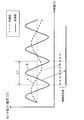
- FIG. 5 is a schematic diagram for explaining a concept of “wavelength during extension” calculated by the controller illustrated in FIG. 4. It is a figure for demonstrating the example of calculation of the wavelength at the time of extension.
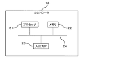
- FIG. 5 is a block diagram illustrating a hardware configuration example of a controller illustrated in FIGS.
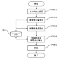
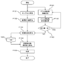
- FIG. 9 It is a flowchart explaining the operation example of the washing-drying machine illustrated in FIG. 9 is a flowchart for explaining an operation example of the signal calculation processing illustrated in FIG. 8. 10 is a flowchart for explaining a modification of the signal calculation process illustrated in FIG. 9. It is a typical longitudinal cross-sectional view of the drum type washing-drying machine which concerns on one Embodiment. It is a typical longitudinal cross-sectional view of the drum type washing-drying machine which concerns on one Embodiment.
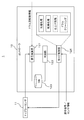
- FIG. 1 is a block diagram illustrating a configuration example of a washing / drying machine 1 according to an embodiment.
- the washing / drying machine 1 illustrated in FIG. 1 may include, for example, a Doppler sensor 11, a controller 12, and a drive mechanism 13.
- the washing / drying machine 1 may be for home use or business use.
- controller 12 may be rephrased as “control unit 12”.
- the Doppler sensor 11 exemplarily transmits a radio wave (may be referred to as “irradiation”) toward the object to be dried under the control of the controller 12 and receives the reflected wave.
- a radio wave may be referred to as “irradiation”
- a non-limiting example of an object to be dried is moisture-containing laundry, and a non-limiting example of the laundry is clothing.
- the object to be dried is accommodated in the washing / drying tank of the washing / drying machine 1.
- the washing / drying tank may be shared by the laundry washing process and the drying process, and may correspond to the “drum” of the drum-type washing / drying machine 1 exemplarily. Focusing on the drying process, the space in the “drum” in which the laundry is stored is an example of a space for drying the object to be dried (may be referred to as “drying space” for convenience).
- the “drying space” may be a space where an object to be dried is placed.
- the “drying space” may correspond to a space in a bathroom where a bathroom dryer is installed.
- the “drying space” may correspond to a space in which an object to be dried is dried by a dryer specialized for the drying process.
- the dryer specialized in the drying process may be for home use or for business use.
- the “drum” arrangement of the washing / drying machine 1 may be a so-called “oblique drum” in which the rotation axis of the drum is shifted obliquely upward with respect to the bottom surface of the washing / drying machine 1, or the rotation axis of the drum is in a direction along the vertical direction.
- Some so-called “vertical placement” may be used, or so-called “horizontal placement” in which the rotation axis of the drum is in a direction perpendicular to the vertical direction.
- the Doppler sensor 11 should just be provided in the position which can irradiate an electromagnetic wave toward the laundry accommodated in the drum of the washing dryer 1 irrespective of drum arrangement
- the Doppler sensor 11 may be installed in the washing / drying machine 1 such that when the drum is in a non-rotating state, the radio wave is irradiated toward a place where the laundry accommodated in the drum is likely to gather due to gravity.
- a specific installation location of the Doppler sensor 11 with respect to the washing / drying machine 1 will be described later with reference to FIGS. 11 and 12.
- the Doppler sensor 11 generates a beat signal by phase-detecting the transmitted radio wave and the reflected wave reflected by the dry object.
- a beat signal is given to the controller 12 as an output signal of the Doppler sensor 11.
- FIG. 2 shows a configuration example of the Doppler sensor 11.
- the Doppler sensor 11 includes, for example, an antenna 111, a local oscillator (Oscillator, OSC) 112, an MCU (Micro Control Unit) 113, a detection circuit 114, an operational amplifier (OP) 115, and a battery 116. May be provided.
- OSC local oscillator
- MCU Micro Control Unit
- OP operational amplifier
- the antenna 111 transmits the radio wave having the oscillation frequency generated by the local oscillator 112 toward the dry object, and receives the radio wave (reflected wave) reflected by the dry object.
- the antenna 111 is shared for transmission and reception, but may be individual for transmission and reception.
- the OSC 112 illustratively oscillates according to the control of the MCU 113 and outputs a signal of a predetermined frequency (may be referred to as a “local signal” for convenience).
- the local signal is transmitted as a transmission radio wave from the antenna 111 and input to the detection circuit 114.
- the oscillation frequency of the OSC 112 (in other words, the frequency of the radio wave transmitted by the Doppler sensor 11) may be, for example, a frequency in the microwave band.
- the microwave band may be a 2.4 GHz band or a 24 GHz band.
- These frequency bands are examples of frequency bands that are allowed to be used indoors by the Japanese Radio Law.
- a frequency band not subject to regulations of the Radio Law may be used for the transmission radio wave of the Doppler sensor 11.
- the MCU 113 controls the oscillation operation of the OSC 112 according to the control of the controller 12.
- the detection circuit 114 detects the phase of the reflected wave received by the antenna 111 and the local signal from the OSC 112 (in other words, the transmission radio wave), and outputs a beat signal.
- the detection circuit 114 may be replaced with a mixer that mixes the transmission radio wave and the reflected wave. Mixing by the mixer may be regarded as equivalent to phase detection.
- the operational amplifier 115 amplifies the beat signal output from the detection circuit 114.
- the amplified beat signal is input to the controller 12.
- the battery 116 illustratively supplies drive power to the MCU 113, the detection circuit 114, and the operational amplifier 115.
- the beat signal obtained by the detection circuit 114 includes an amplitude change according to a change in the moisture content of the dry object (in other words, “dryness”), and a frequency change according to the movement of the dry object. , Appears.
- the reflected wave attenuates.
- the amplitude value of the reflected wave tends to increase as the laundry is dried, and therefore the amplitude value of the beat signal also tends to increase.
- the Doppler effect causes a change in frequency and amplitude value corresponding to the movement to appear in the reflected wave.
- the frequency and amplitude value of the beat signal tend to increase as the amount of movement of the laundry (in other words, the relative speed with respect to the Doppler sensor 11) increases.
- the reflected wave of the radio wave applied to the laundry changes in both amplitude and frequency as the moisture-containing laundry is dried, so that the change appears as a change in the amplitude and frequency of the beat signal.
- the beat signal includes information indicating changes in both the amount of moisture and the amount of movement of the laundry.
- the “dryness” of the laundry can be determined (may be referred to as “detection” or “measurement”) based on changes in the amplitude and frequency of the beat signal obtained by the Doppler sensor 11.
- the “dryness” of the laundry may be rephrased as the “wetness” of the laundry. Further, the “dryness” or “wetness” of the laundry may be collectively referred to as “dry state” of the laundry for convenience.
- the amplitude value of the beat signal increases as the laundry is dried, and the amplitude value remains high if the laundry dries to a certain extent. Moreover, since the weight of the laundry becomes lighter as the laundry is dried, the speed of movement of the laundry is increased and the frequency of the beat signal is increased even at the same drum rotation speed and air blowing rate. If the laundry dries more than a certain amount, the frequency will stay high.
- the controller 12 may control the drive mechanism 13 of the washing / drying machine 1 as illustrated in FIGS. 1 and 3.
- the drive mechanism 13 may include, for example, electrical and mechanical elements such as a fan 131, a heater 132, a motor 133, a drain valve 134, and a water supply valve 135.
- the fan 131 sends air to the space in the drum, which is an example of the drying space.
- the start, stop, and rotation speed of the fan 131 may be controlled by the controller 12.
- the heater 132 illustratively heats the air sent to the drum by the fan 131. Thereby, for example, it is possible to blow warm air to the drum during the drying operation of the washing / drying machine 1.
- the start, stop, temperature, etc. of the heater 132 may be controlled by the controller 12.
- the blowing of warm air to the drum is an example of controlling the inflow of air into the drum, and is an example of controlling the operation of the drying process by the washing / drying machine 1.
- the motor 133 is exemplarily attached to the drum rotation shaft and rotates the drum rotation shaft.
- the rotation direction of the motor 133 may be reversible.
- the start, stop, rotation direction, rotation speed, and the like of the motor 133 may be controlled by the controller 12.
- the drain valve 134 is, for example, opened when the washing / drying machine 1 is dehydrated, and drains from the drum.
- the water supply valve 135 is opened during the washing operation of the washing / drying machine 1 to supply water to the drum.
- the opening degree of the drain valve 134 and the water supply valve 135 may be controlled by actuators not shown.
- the actuator may be controlled by the controller 12.
- an operation unit 141 may be connected to the controller 12.
- the operation unit 141 is operated by a user of the washing / drying machine 1, and a signal corresponding to the operation (may be referred to as an “operation signal” for convenience) is input to the controller 12. Control according to the operation signal is performed by the controller 12.
- one or more physical quantity sensors may be connected to the controller 12 in addition to the Doppler sensor 11 described above.
- the physical quantity sensor are a water level sensor 142, a temperature sensor 143, a humidity sensor 144, a door opening / closing sensor 145, a mass sensor 146, a rotation speed sensor 147, and the like.
- the water level sensor 142 illustratively senses the water level in the drum.
- the temperature sensor 143 illustratively senses the temperature in the drum.
- the humidity sensor 144 illustratively senses the humidity in the drum.
- the door opening / closing sensor 145 senses opening / closing of the door of the washing / drying machine 1.
- the mass sensor 146 senses the mass (or weight) of the laundry contained in the drum.
- the rotation speed sensor 147 illustratively senses the rotation speed of the drum rotation shaft (in other words, the drum rotation speed).
- the controller 12 controls the drive mechanism 13 on the basis of information sensed by the various physical quantity sensors as described above (which may be referred to as “sensor information” for convenience) to operate the washing / drying machine 1 (“ It may be referred to as “processing” or “operation”).
- one or both of the drain valve 134 and the water supply valve 135 may be controlled based on the sensor information of the water level sensor 142. With this control, it is possible to automate the water supply and drainage of the washing / drying machine 1.
- any of the fan 131, the heater 132, and the motor 133 may be controlled based on the sensor information of the temperature sensor 143 and the humidity sensor 144.
- the drying operation of the washing / drying machine 1 can be automated.
- the start and stop of the motor 133 may be controlled based on the sensor information of the door opening / closing sensor 145.
- the controller 12 may stop driving the motor 133 when the sensor information of the door opening / closing sensor 145 indicates the open state of the door of the washing / drying machine 1.
- any one of the fan 131, the heater 132, the motor 133, the drain valve 134, and the water supply valve 135 is selected according to the mass of the laundry stored in the drum. It may be controlled manually or in combination.
- the water supply amount, the drum rotation speed, and the like may be adaptively controlled so that an efficient washing operation is realized.
- the air flow rate, the heater temperature, the drum rotation speed, and the like may be adaptively controlled so that an efficient drying process is realized.
- FIG. 4 shows a functional configuration example of the controller 12.
- the controller 12 may include, for example, a signal calculation unit 121, a determination unit 122, a database (DB) 123, and a mode control unit 124.
- DB database
- the signal calculation unit 121 illustratively calculates the “wavelength during extension” of the beat signal output from the Doppler sensor 11 (which may be referred to as “Doppler sensor output” for convenience).
- the “wavelength at extension” is, for example, the length when the signal waveform per unit time of the Doppler sensor output is linearly extended. Therefore, the “wavelength during extension” is a different concept from the normal “wavelength”.
- FIG. 5 schematically illustrates the concept of “wavelength during extension”.
- the horizontal axis in FIG. 5 indicates time [t], and the vertical axis in FIG. 5 indicates the output voltage [V] of the Doppler sensor 11.
- the change in the output voltage of the Doppler sensor 11 may be regarded as corresponding to the change in the amplitude of the reflected wave from the laundry.
- the signal waveform indicated by the dotted line A illustratively represents an amplitude change with respect to time of the reflected wave when the laundry is not yet dried.
- a signal waveform indicated by a solid line B represents a change in amplitude with respect to time of the reflected wave when it may be determined that the laundry is dry.
- the “wavelength during extension” corresponds to the length when the signal waveform per unit time ( ⁇ T) indicated by the dotted line A and the solid line B is linearly extended in the time direction. To do.
- the “wavelength during extension” corresponds to the length of the locus drawn in the time domain according to the change of the output amplitude value of the Doppler sensor 11 in the unit time ⁇ T.
- the unit time ⁇ T may be a “second” unit or a “minute” unit.
- the amplitude and frequency of the Doppler sensor output will not change, or even if it changes, it will fall within a certain range. Therefore, the “wavelength during extension” will be a certain value or a value within the certain range. Converge (may be paraphrased as “becomes stable”).
- the laundry is dry” according to the convergence of the “wavelength during extension”. For example, if the state in which the “wavelength during extension” converges continues for a certain time (for example, several tens of seconds to several minutes), it can be determined that “the laundry is dry”.
- the “wavelength during extension” is illustratively stored in the DB 123 sequentially with the amplitude value of the Doppler sensor output received by the signal calculation unit 121 in a certain period (which may be referred to as “sampling period”). Then, it can be calculated by adding the amount of change in the amplitude value over a unit time.
- the horizontal axis of FIG. 6 represents time [t], and the vertical axis of FIG. 6 represents the output amplitude (voltage, [V]) of the Doppler sensor 11.
- N is an integer representing a timing label.
- A is a real number that the voltage value [V] can take, and “ ⁇ ” is an integer representing a label of the voltage value.
- the sampling timing interval may be constant or different.
- the signal calculation unit 121 illustratively obtains the amount of amplitude change between sampling timings based on the amplitude value (voltage value) obtained at each sampling timing. For example, the signal calculation unit 121 may obtain a difference between amplitude values at adjacent sampling timings as an amplitude change amount between the sampling timings.
- the signal calculation unit 121 repeatedly performs such calculation over the number of samplings per unit time, and the obtained amplitude change amount is expressed as
- the “wavelength during extension” can be calculated.
- the unit of the “wavelength during extension” is, for example, “voltage / time” (V / min). expressed.
- the accuracy of the amplitude change amount obtained will decrease, and if it is too large, the calculation load will increase and calculation delay may occur, so it is set in a realistic range. It's okay.
- the “wavelength during extension” may be time averaged over a predetermined time. For example, the average of 60 “wavelengths during extension” obtained per minute with a unit time of 1 second may be taken. By taking the average, the noise component of the amplitude value can be removed or reduced.
- the DB 123 stores the amplitude value used for calculating the “extension wavelength” in the signal calculation unit 121 and the “extension wavelength” calculated by the signal calculation unit 121.
- the DB 123 may be realized by a storage medium such as a memory.
- a RAM Random Access Memory
- a flash memory or the like may be applied as the storage medium.
- the signal calculation unit 121 may compare the “wavelength during extension” stored in the DB 123 and calculate the change over time. If there is no time change of the “wavelength during extension” over a certain time (for example, several tens of seconds to several minutes) (or if it can be ignored even if there is a time change or is within an allowable range), the determination of FIG. The unit 122 may determine that the “wavelength at extension” has converged.
- the determination unit 122 determines whether or not the laundry has dried by determining whether or not the “wavelength during extension” has converged as described above (in other words, whether or not the drying process may be terminated). judge. The determination result may be given to the mode control unit 124.
- the mode control unit 124 exemplarily controls the operation of the washing / drying machine 1 (may be referred to as “operation mode”).
- the “driving mode” may include a washing mode for performing a washing process and a drying mode for performing a drying process.
- the “operation mode” may include a finishing mode in which the laundry is finished, a drum cleaning mode in which the laundry dryer 1 autonomously performs cleaning of the drum, and the like.
- the control of the “operation mode” by the mode control unit 124 may be performed based on an operation signal corresponding to an operation on the operation unit 141 and sensor information of various sensors 142 to 147.
- the control of the “operation mode” may include drive control of the Doppler sensor 11.
- the mode control unit 124 may start transmission of radio waves by the Doppler sensor 11 in response to the start of the drying mode. Further, the mode control unit 124 may stop the transmission of radio waves by the Doppler sensor 11 in accordance with the end of the drying mode. However, the timing for stopping the radio wave transmission may not be the same as the end of the drying mode.
- the Doppler sensor 11, the signal calculation unit 121, and the determination unit 122 may be regarded as forming a “dryness detection device” for laundry, which is an example of an object to be dried.
- the signal calculation unit 121 and the determination unit 122 may be regarded as forming a “detection unit” that detects the “dryness” of the laundry based on the amplitude and frequency of the Doppler sensor output.
- the mode control unit 124 may be regarded as a “control unit” that controls the drying process based on the detection result of the “detection unit”.
- FIG. 7 shows a hardware configuration example of the controller 12 described above.
- the controller 12 may include a processor 21, a memory 22, and an input / output interface (IF) 23.
- the processor 21, the memory 22, and the input / output IF 23 may be connected to each other via a bus 24 so that they can communicate with each other.
- the processor 21 exemplarily functions as the signal calculation unit 121, the determination unit 122, and the mode control unit 124 illustrated in FIG. 4 by appropriately reading and operating programs and data stored in the memory 22.
- the “program” may be referred to as “software” or “application”.
- the processor 21 is an example of an arithmetic device, an arithmetic circuit, or an arithmetic device having an arithmetic capability.
- a CPU Central Processing Unit
- DSP Digital Signal Processor
- the controller 12 including the arithmetic device may be realized, for example, by an IC (Integrated Circuit), an LSI (Large Scale Integration), an FPGA (Field Programmable Gate Array), or the like.
- the memory 22 stores a program and data read by the processor 21 or generated by the processor 21.
- the memory 22 is an example of a storage medium, and may be a RAM, a flash memory, or the like.
- the DB 123 illustrated in FIG. 4 may be implemented.
- the input / output IF 23 is an example of an interface that enables connection and communication between the controller 12 and an external device. As illustrated in FIGS. 1 and 3, the Doppler sensor 11, the drive mechanism 13, the operation unit 141, and Various sensors 142 to 147 may be connected.
- the input / output IF 23 may include a wireless or wired communication IF.
- the communication IF may be connected to the bus 24 as an IF different from the input / output IF 23.
- the washer / dryer 1 may be able to communicate with an external communication device wirelessly or by wire.
- the external communication device may correspond to a user terminal such as a mobile phone (including a “smart phone”), a personal computer (PC), or a tablet PC held by the user of the washing / drying machine 1.
- the external communication device may correspond to a server provided in a LAN (Local Area Network) or the Internet.
- the server may be a cloud server provided in a cloud data center.
- the mode control unit 124 starts the drying process. Good (processing P11).
- the mode control unit 124 may switch the operation mode of the washing / drying machine 1 from the washing operation mode to the drying operation mode.
- the drying process may be automatically started according to the end of the washing process as in this example, or may be manually started according to the user's operation on the operation unit 141 (see FIG. 3). .
- the mode control unit 124 illustratively controls the fan 131 and the heater 132 to start supplying hot air to the drum (in other words, “air blowing”). Good (processing P12).
- the Doppler sensor output is not affected by the temperature change or hardly affected by the temperature change. It may be considered that it does not affect the calculation of.
- the mode control unit 124 may control the driving of the Doppler sensor 11 to start radio wave transmission into the drum (process P13). Note that the processing order of the processing P12 and the processing P13 is reversible. Further, the process P12 and the process P13 may be performed in parallel by the mode control unit 124.
- the Doppler sensor 11 receives a reflected wave of the transmission radio wave (process P14). Therefore, as described above, a beat signal corresponding to the reflected wave of the transmission radio wave is generated by the Doppler sensor 11 and input to the controller 12 (for example, the signal calculation unit 121).
- the signal calculation unit 121 performs, for example, an extension wavelength calculation and a drying process end determination based on the calculated extension wavelength by operating according to the flowchart shown in FIG.
- the signal calculation unit 121 calculates an amplitude change amount as described in FIG. 6 (process P152), and calculates the calculated amplitude change amount. Based on this, the extension wavelength is calculated (process P153).
- the signal calculation unit 121 calculates the time change of the extension wavelength over a certain threshold time (process P154). Based on the calculated time change, the determination unit 122 may determine the end of the drying process (process P155).
- the determination unit 122 converges the “wavelength at extension” if the time change of the “wavelength at extension” does not exist for a certain threshold time (or can be ignored even if there is a time change). It may be determined that the laundry has been dried. If it is determined that the “wavelength during extension” has not converged, the determination unit 122 determines that drying of the laundry has not been completed.
- the determination result by the determination unit 122 is given to the mode control unit 124, and the mode control unit 124 checks whether or not the determination result indicates “drying completion” as illustrated in FIG. 8 (process P16). .
- the mode control unit 124 continues the drying process until a determination result indicating “drying complete” is received. It's okay.
- the mode control unit 124 may perform a drying end process (process P17). For example, the mode control unit 124 may stop the supply of hot air into the drum by controlling the fan 131 and the heater 132 (Process P18). In addition, the mode control unit 124 may stop the rotation of the drum by stopping the driving of the motor 133.
- the mode control unit 124 may finish the processing, but may additionally perform finishing processing or drum cleaning automatically or in response to an operation signal from the operation unit 141. .
- the dryness of the laundry whose amount of movement changes according to the change in the moisture content is accurately detected based on the change in the amplitude value and frequency of the Doppler sensor output. be able to.
- the “wavelength during extension” that changes according to changes in the amplitude value and frequency of the Doppler sensor output includes information on both the amount of movement of the laundry and the amount of radio wave absorption. It can be determined that the laundry is dry by the convergence of the “wavelength”.
- the laundry in the drum is moved by the rotation of the drum, and the amount of movement also changes depending on the progress of drying. For example, when the rotational speed of the drum is higher than a certain level, the laundry easily rotates together with the drum while being stuck to the inner wall surface of the drum due to centrifugal force.
- the laundry may fall vertically downward within the drum at around 1/4 to 1/2 rotation of the drum. Even if the rotation speed of the drum is slow, it may be less likely that the laundry falls vertically downward in the drum as the laundry is dried and lightens.
- the amount of movement of the laundry changes depending on the rotation speed of the drum, and also changes depending on the progress of the drying of the laundry (content of water content).
- the amount of movement of the laundry may vary depending on a combination of the wetness of the laundry and the rotational speed of the drum. Further, the drum rotation speed is not always kept constant during the drying process.
- washing in the drying process of the washing dryer 1 is performed based on the information “wavelength during extension” including both information of the amplitude value change and the frequency change of the Doppler sensor output. It is possible to accurately detect the dryness of an object.
- the control accuracy of the drying operation by the mode control unit 124 can be improved, and excessive or insufficient drying operation can be prevented or suppressed. Therefore, it is possible to improve the efficiency of the drying operation. For example, it is possible to save energy in the drying operation and, in turn, save energy in the washing dryer 1.
- the signal calculation unit 121 (see FIG. 4) of the controller 12 may additionally perform processes P161 to P163 in parallel with the processes P151 to P155 illustrated in FIG.
- the signal calculation unit 121 calculates the amount of change in the drum rotation speed per unit time (process P162). ), It is determined whether or not the amount of change is constant (processing P163).
- the signal calculation unit 121 If the change amount of the drum rotation number is constant (YES in process P163), the signal calculation unit 121 returns to process P161 without correcting the “wavelength during extension”, and monitors the change amount of the drum rotation number. You may continue.
- the signal calculation unit 121 excludes the amplitude change amount obtained in process P152 from the candidates for addition to the “extension wavelength”. It's okay.
- the signal calculation unit 121 determines the amplitude change amount.
- the amplitude change amount that is considered to decrease the reliability according to the control is excluded from the candidates for addition to the ⁇ extension wavelength '' and is The “wavelength” is corrected. Therefore, it is possible to prevent or suppress a decrease in determination accuracy as to whether or not the “stretching wavelength” has converged stably.
- FIG.11 and FIG.12 are schematic longitudinal sectional views of the drum type laundry dryer 1 which is an example of the laundry dryer 1.
- the drum type washing and drying machine 1 may include a housing 2 that is a main body and a drum 3 that is an example of a washing and drying tank provided in the housing 2. .
- the drum 3 is attached to the drum rotation shaft 8 and is rotatable around the drum rotation shaft 8 in the housing 2.
- the drum rotation shaft 8 may be rotationally driven by the motor 133 illustrated in FIGS. 1 and 3.
- the motor 133 may be rotatable in both forward and reverse directions.
- the drum 3 may be disposed so that the opening 3a faces the upper surface obliquely (for example, about 45 degrees) with respect to the bottom surface 2a of the housing 2.
- the drum 3 may be installed in the housing 2 such that the drum rotation shaft 8 forms an angle of about 45 degrees obliquely upward with respect to the bottom surface 2 a of the housing 2.
- the opening / closing door (door) 4 of the washing / drying machine 1 may be provided in the housing 2 in the direction in which the opening 3a of the drum 3 faces. With the door 4 opened, the laundry to be washed or dried is accommodated in the drum 3 through the opening 3 a of the drum 3.
- a water supply pipe 5, a drain pipe 6, and a blower pipe 7 may be provided as an example.
- the water supply pipe 5 forms a water supply path in the washing / drying machine 1.
- a water supply valve 135 illustrated in FIGS. 1 and 3 may be provided in the water supply pipe 5. When the water supply valve 135 is controlled to be in the open state, water is supplied to the drum 3 through the water supply pipe 5.
- the drainage pipe 6 forms a drainage channel in the washing / drying machine 1.
- the drain pipe 6 may be provided with the drain valve 134 illustrated in FIGS. 1 and 3. When the drain valve 134 is controlled to be opened, drainage from the drum 3 is performed through the drain pipe 6.
- the blower pipe 7 forms a blower passage in the washing / drying machine 1.
- warm air generated by the fan 131 and the heater 132 illustrated in FIGS. 1 and 3 may flow through the air pipe 7.
- the warm air may be supplied to the space in the drum 3 from one opening of the blower pipe 7 and then sent out again to the space in the drum 3 through the other opening of the blower pipe 7.
- the warm air may circulate through the space in the drum 3 and the blower pipe 7.
- the Doppler sensor 11 emits radio waves from the vicinity of the center of the bottom surface of the drum 3 toward the side surface in the drum 3 where the laundry is likely to gather by gravity. It may be installed at a position.
- the Doppler is arranged so that the irradiation direction of the radio wave is directed to the side wall in the drum 3 where the laundry is easily gathered on the drum rotation shaft 8 partially protruding at the center of the bottom surface of the drum 3.
- a sensor 11 may be installed.
- subjects shading in FIG. 11 has shown typically the irradiation area
- the Doppler sensor 11 may be attached to the drum rotation shaft by a structure or member that can support the Doppler sensor 11 in a non-rotating manner even when the drum 3 rotates.
- the Doppler sensor 11 may be covered with a cover made of a material that can transmit radio waves to be irradiated.
- the drum rotating shaft 8 to which the Doppler sensor 11 is attached may illustratively have a hollow structure.
- a wire that electrically connects the Doppler sensor 11 and the controller 12 may be provided in a hollow portion of the hollow structure. By providing the wiring in the hollow portion, it is possible to prevent the wiring from being twisted or tangled by the rotation of the drum 3.
- the Doppler sensor 11 attaching the Doppler sensor 11 to the drum rotating shaft 8, the influence of the vibration of the washing / drying machine 1 transmitted to the Doppler sensor 11 when the drum 3 rotates can be suppressed or alleviated.
- the influence of the vibration of the washing / drying machine 1 on the reflected wave received by the Doppler sensor 11 can be suppressed or reduced. Therefore, it can suppress that the precision of the dryness determination of the laundry based on the wavelength at the time of extension using the Doppler sensor 11 falls.
- the Doppler sensor 11 may set the irradiation direction of the radio waves so that the radio waves are irradiated obliquely downward from the drum rotation shaft 8.
- the radio wave irradiation direction of the Doppler sensor 11 is set obliquely downward, it is possible to suppress or alleviate radio waves passing through the door 4 and leaking outside the washing / drying machine 1.
- the door 4 of the washing / drying machine 1 may be provided with a “view window” made of transparent reinforced plastic so that the state of the washing operation and the drying operation can be visually recognized from the outside.
- a “view window” made of transparent reinforced plastic so that the state of the washing operation and the drying operation can be visually recognized from the outside.
- the radio wave irradiation direction (“directivity” of the Doppler sensor 11 is transmitted so that the radio wave is transmitted in a direction avoiding the direction from the drum rotation shaft 8 toward the door 4 of the washing / drying machine 1. May be referred to as “sex”.) May be set.
- the Doppler sensor 11 is installed on the door 4 side of the washing / drying machine 1.
- the Doppler sensor 11 may be installed at a position where radio waves are irradiated from the door 4 side of the washing / drying machine 1 toward the side wall of the drum 3 where the laundry is likely to gather by gravity. .
- the Doppler sensor 11 may be attached to the bearing of the door 4 or the vicinity thereof so that the irradiation direction of the radio wave faces the side wall of the drum 3 where the laundry is easily collected.
- the Doppler sensor 11 may be attached to the door 4 itself.
- subjects shading in FIG. 12 has shown typically the irradiation area
- radio waves As schematically illustrated in FIG. 12, by radiating radio waves from the door 4 side toward the space in the drum 3, from the door 4 side of the washing / drying machine 1 (for example, the above-described “view window”).
- the leakage of radio waves can be suppressed or alleviated.
- the movement affects the reflected wave received by the Doppler sensor 11. Can be suppressed or mitigated. Therefore, it can suppress that the precision of the dryness determination of the laundry based on the wavelength at the time of extension using the Doppler sensor 11 falls.
- the “wavelength during extension” includes information indicating a change in the reflected wave according to the vibration of the washing / drying machine 1.
- extension wavelength correction may be performed in the same manner as the above-described modification. For example, if it can be understood that the change in the frequency depends on the change in the drum rotation speed, the amplitude change amount added to the “wavelength during extension” may be selected and excluded according to the change in the drum rotation speed.
- the controller 12 may wait for the calculation of the “wavelength during extension” for a predetermined time after starting the transmission of radio waves by the Doppler sensor 11 in response to the start of the drying operation.
- the controller 12 may wait for several seconds to several tens of seconds from the start of radio wave transmission by the Doppler sensor 11 and then start calculating the “wavelength during extension”. As a result, even if the “wavelength during extension” is calculated, it is possible to avoid unnecessary calculation of the “wavelength during extension” during the time when the reliability is considered to be low. Therefore, for example, the power consumption of the controller 12 can be reduced, which contributes to energy saving of the washing / drying machine 1.
- the degree of dryness of the laundry is estimated by detecting changes in the interior temperature and intake / exhaust temperature of the washing / drying machine 1 with a temperature sensor, and using an optical sensor. It may be estimated based on a change in the amount of absorbed light.
- the estimation using the temperature sensor is based on the premise that the heater temperature is controlled to be constant during the drying operation. If the heater temperature is controlled, the estimation accuracy of the dryness is greatly reduced. In addition, in the estimation using the optical sensor, moisture and dust are likely to adhere to the washer / dryer 1, so that moisture and dust are attached to the light emitting surface and the light receiving surface of the optical sensor, and the sensing sensitivity is increased. It tends to decline.
- the Doppler sensor 11 is more resistant to environmental changes in the washing / drying machine 1 than a temperature sensor or an optical sensor. For this reason, it is possible to improve the detection accuracy of the dryness, and to improve the efficiency of the drying operation.
- the signal calculation unit 121 of the controller 12 may calculate the “wavelength during extension” by averaging beat signals obtained by the plurality of Doppler sensors 11 or applying weighting according to, for example, installation locations.
- the drying state of the laundry in the drum 3 of the laundry dryer 1 is detected, and the drying operation of the laundry dryer 1 is controlled based on the detection result (for example, An example of stopping) has been described.
- the detection result for example, An example of stopping
- the example in which the detection result by the dryness detection device using the Doppler sensor 11 is linked to the control of the drying operation of the washing dryer 1 has been described.
- the dryness detection device using the Doppler sensor 11 may be provided in a bathroom dryer, for example.
- the dryness detection result of the laundry in the bathroom by the dryness detection device may be linked to the control of the drying operation of the bathroom dryer (for example, control of a dehumidifier, a ventilation fan, etc.). .
- the dryness detection device using the Doppler sensor 11 can be widely applied to the detection of the dryness (or wetness) of an object to be dried that may cause movement in the drying process, and the device or product that uses the detection result for control. Can be widely applied or applied to.
- the “dryness detection device” may be referred to as “dryness measurement device” or “dryness determination device”, or may be referred to as “dryness sensor”.
Landscapes
- Engineering & Computer Science (AREA)
- Textile Engineering (AREA)
- Control Of Washing Machine And Dryer (AREA)
Abstract
洗濯乾燥機(1)は、ドップラーセンサ(11)と、制御部(12)と、を備えてよい。ドップラーセンサ(11)は、乾燥の対象物が収容される空間内に電波を送信する。制御部(12)は、洗濯処理に応じた動作から乾燥処理に応じた動作への切り替わりに応じて、ドップラーセンサ(11)に電波の送信を開始させ、ドップラーセンサ(11)が受信した反射波に応じて、前記乾燥処理の動作を制御してよい。
Description
本明細書に記載する技術は、洗濯乾燥機、洗濯乾燥機の制御装置、乾き度検出装置、及び、乾燥機に関する。
洗濯物を浴室において乾燥させる浴室乾燥装置が知られている。また、マイクロ波センサ等の電波センサによって洗濯物に電波を照射して洗濯物の水分量を検知することで、浴室乾燥装置の乾燥運転(「乾燥処理」と称してもよい。)を制御する技術も知られている。
例えば、洗濯物に照射した電波の反射量は洗濯物に含まれる水分量に応じて変化するため、反射波の受信電力を周期的に取得し、受信電力の時間微分が正から負になった後に、洗濯物の乾燥が完了したと判定して、乾燥ファン及び加熱ヒータを停止する。
洗濯物の乾燥が進むにつれて洗濯物に含まれる水分量が減少すると、洗濯物の重量は軽くなるため、洗濯物は動きやすくなる。従来技術は、洗濯物の乾燥が進むにつれて洗濯物が動きやすくなる点に着眼していない。
そのため、従来技術では、洗濯物の乾き度を精度良く判定できないことがある。洗濯物の乾き度の判定精度が低下すると、結果的に、乾燥運転の制御精度が低下し、乾燥運転の過不足が生じ得る。乾燥運転に過不足が生じることは、乾燥運転の効率低下につながるため、例えば、乾燥運転の省エネ化の妨げになり得る。
1つの側面では、本明細書に記載する技術の目的の1つは、乾燥処理の効率化を図ることにある。
1つの側面において、洗濯乾燥機は、ドップラーセンサと、制御部と、を備えてよい。ドップラーセンサは、乾燥の対象物が収容される空間内に電波を送信する。制御部は、洗濯処理に応じた動作から乾燥処理に応じた動作への切り替わりに応じて、前記ドップラーセンサに電波の送信を開始させ、前記ドップラーセンサが受信した反射波に応じて、前記乾燥処理の動作を制御してよい。
また、1つの側面において、洗濯乾燥機の制御装置は、洗濯乾燥機の洗濯処理に応じた動作から乾燥処理に応じた動作への切り替わりに応じて、前記乾燥処理による乾燥の対象物が収容される空間内に電波を送信するドップラーセンサに、前記電波の送信を開始させ、前記ドップラーセンサが受信した反射波に応じて、前記乾燥処理の動作を制御する制御部を備えてよい。
更に、1つの側面において、乾き度検出装置は、ドップラーセンサと、検出部と、を備えてよい。ドップラーセンサは、乾燥対象物が収容される空間内に電波を送信する。検出部は、前記電波の送信に応じて前記ドップラーセンサが受信した反射波の振幅及び周波数に基づいて、前記乾燥対象物の乾き度を検出してよい。
また、1つの側面において、乾燥機は、ドップラーセンサと、検出部と、制御部と、を備えてよい。ドップラーセンサは、乾燥対象物が収容される空間内に電波を送信する。検出部は、前記電波の送信に応じて前記ドップラーセンサが受信した反射波の振幅及び周波数に基づいて、前記乾燥対象物の乾き度を検出してよい。制御部は、前記検出部によって検出された乾き度に応じて、前記乾燥対象物の乾燥処理を制御してよい。
1つの側面として、乾燥処理の効率化を図ることができる。
以下、図面を参照して実施の形態を説明する。ただし、以下に説明する実施形態は、あくまでも例示であり、以下に明示しない種々の変形や技術の適用を排除する意図はない。また、以下に説明する各種の例示的態様は、適宜に組み合わせて実施しても構わない。なお、以下の実施形態で用いる図面において、同一符号を付した部分は、特に断らない限り、同一若しくは同様の部分を表す。
図1は、一実施形態に係る洗濯乾燥機1の構成例を示すブロック図である。図1に示す洗濯乾燥機1は、例示的に、ドップラーセンサ11と、コントローラ12と、駆動機構13と、を備えてよい。洗濯乾燥機1は、家庭用でもよいし業務用でもよい。なお、「コントローラ12」は、「制御部12」と言い換えてもよい。
ドップラーセンサ11は、例示的に、コントローラ12の制御に応じて、乾燥対象物に向けて電波を送信(「照射」と称してもよい。)し、その反射波を受信する。乾燥対象物の非限定的な一例は、水分を含んだ洗濯物であり、洗濯物の非限定的な一例は、衣類である。乾燥対象物は、洗濯乾燥機1の洗濯乾燥槽に収容される。
洗濯乾燥槽は、洗濯物の洗濯処理と乾燥処理とに共用であってよく、例示的に、ドラム式洗濯乾燥機1の「ドラム」に対応してよい。乾燥処理に着目すれば、洗濯物が収容される「ドラム」内の空間は、乾燥対象物を乾燥させる空間(便宜的に「乾燥空間」と称してもよい。)の一例である。
なお、「乾燥空間」は、乾燥対象物が置かれる空間であればよい。例えば、「乾燥空間」は、浴室乾燥機の設置された浴室内の空間に対応してもよい。また、「乾燥空間」は、乾燥処理に特化した乾燥機によって乾燥対象物が乾燥される空間に対応してもよい。乾燥処理に特化した乾燥機は、家庭用でもよいし業務用でもよい。
洗濯乾燥機1の「ドラム」配置は、ドラムの回転軸が洗濯乾燥機1の底面に対して斜め上方にずれた所謂「斜めドラム」でもよいし、ドラムの回転軸が鉛直方向に沿う方向である所謂「縦置き」でもよいし、ドラムの回転軸が鉛直方向と直交する方向である所謂「横置き」でもよい。
ドップラーセンサ11は、ドラム配置に関わらず、洗濯乾燥機1のドラム内に収容される洗濯物に向けて電波を照射できる位置に設けられればよい。例えば、ドップラーセンサ11は、ドラムが非回転状態のときに、ドラム内に収容された洗濯物が重力によって集まり易い箇所に向けて電波が照射されるように洗濯乾燥機1に設置されてよい。ドップラーセンサ11の洗濯乾燥機1に対する具体的な設置箇所については、図11及び図12により後述する。
ドップラーセンサ11は、送信した電波と、当該電波が乾燥対象物で反射した反射波と、を位相検波してビート信号を生成する。ビート信号がドップラーセンサ11の出力信号としてコントローラ12に与えられる。
図2に、ドップラーセンサ11の構成例を示す。図2に示すように、ドップラーセンサ11は、例示的に、アンテナ111、ローカル発振器(Oscillator, OSC)112、MCU(Micro Control Unit)113、検波回路114、オペアンプ(OP)115、及び、バッテリ116を備えてよい。
アンテナ111は、ローカル発振器112で生成された発振周波数をもつ電波を乾燥対象物に向けて送信し、また、乾燥対象物で反射した電波(反射波)を受信する。なお、図2の例において、アンテナ111は、送受信に共用であるが、送受信に個別であってもよい。
OSC112は、例示的に、MCU113の制御に応じて発振動作して、所定周波数の信号(便宜的に「ローカル信号」と称してよい。)を出力する。ローカル信号は、アンテナ111から送信電波として送信されると共に、検波回路114に入力される。
OSC112の発振周波数(別言すると、ドップラーセンサ11が送信する電波の周波数)は、例示的に、マイクロ波帯の周波数であってよい。マイクロ波帯は、例示的に、2.4GHz帯でもよいし、24GHz帯でもよい。これらの周波数帯は、日本の電波法で屋内での使用が認められている周波数帯の一例である。電波法の規制を受けない周波数帯を、ドップラーセンサ11の送信電波に用いても構わない。
MCU113は、コントローラ12の制御に応じてOSC112の発振動作を制御する。
検波回路114は、アンテナ111で受信された反射波とOSC112からのローカル信号(別言すると、送信電波)と、を位相検波してビート信号を出力する。なお、検波回路114は、送信電波と反射波とをミキシングするミキサに置換されてもよい。ミキサによるミキシングは、位相検波と等価であると捉えてよい。
オペアンプ115は、検波回路114から出力されるビート信号を増幅する。増幅されたビート信号は、コントローラ12に入力される。
バッテリ116は、例示的に、MCU113、検波回路114及びオペアンプ115に駆動電力を供給する。
ここで、検波回路114によって得られるビート信号には、乾燥対象物の水分含有量(別言すると「乾き度」)の変化に応じた振幅変化と、乾燥対象物の動きに応じた周波数変化と、が現われる。
例えば、洗濯物が濡れている状態では水分量が多いため、電波は洗濯物に吸収されやすく反射量が減る(別言すると、反射波が減衰する)傾向にある。これに対し、洗濯物が乾いている状態では水分量が少ないため電波は洗濯物に吸収されにくくなり反射量が増える傾向にある。したがって、洗濯物の乾燥が進むにつれて反射波の振幅値は大きくなる傾向にあり、故に、ビート信号の振幅値も大きくなる傾向にある。
その一方で、洗濯物の乾燥が進んで水分量が減るにつれて、洗濯物の重量が軽くなるため、洗濯物は動きやすくなる。洗濯物が動くと、ドップラー効果によって、その動きに応じた周波数及び振幅値の変化が反射波に現われる。
そのため、ビート信号にも洗濯物の動きに応じた周波数及び振幅値の変化が現われる。例えば、洗濯物の動き量(別言すると、ドップラーセンサ11に対する相対速度)が大きくなるほど、ビート信号の周波数及び振幅値は大きくなる傾向にある。
簡潔に云えば、洗濯物に照射した電波の反射波は、水分を含んだ洗濯物の乾燥が進むにつれて振幅及び周波数の双方が変化するため、当該変化がビート信号の振幅及び周波数の変化として現われる。別言すると、ビート信号には、洗濯物の水分量と動き量との双方の変化を示す情報が含まれる。
したがって、ドップラーセンサ11で得られるビート信号の振幅及び周波数の変化を基に、洗濯物の「乾き度」を判定(「検出」あるいは「測定」と称してもよい。)することができる。なお、洗濯物の「乾き度」は、洗濯物の「濡れ度」と言い換えてもよい。また、洗濯物の「乾き度」あるいは「濡れ度」は、便宜的に、洗濯物の「乾燥状態」と総称してもよい。
例えば、洗濯物の乾燥が進むにつれてビート信号の振幅値は大きくなり、洗濯物がある程度以上乾けば、振幅値は高止まりする。また、洗濯物の乾燥が進むにつれて、洗濯物の重量が軽くなるため、同じドラム回転数及び送風量でも、洗濯物の動く速度が速くなり、ビート信号の周波数が高くなる。洗濯物がある程度以上乾けば、周波数も高止まりする。
したがって、ビート信号の振幅値及び周波数が高止まりした状態が、或る時間にわたって継続すれば、「洗濯物が乾いた」と判定してよい。以上のような乾き度の判定は、例示的に、コントローラ12で行なってよい。
コントローラ12は、図1及び図3に例示するように、洗濯乾燥機1の駆動機構13を制御してよい。駆動機構13には、例示的に、ファン131、ヒータ132、モータ133、排水弁134、及び、給水弁135等の電気的要素や機械的要素が含まれてよい。
例示的に、ファン131は、乾燥空間の一例であるドラム内の空間に風を送り出す。ファン131の始動、停止、及び、回転数等が、コントローラ12によって制御されてよい。
ヒータ132は、例示的に、ファン131によってドラムに送り出される空気を加熱する。これにより、例えば、洗濯乾燥機1の乾燥運転時に、ドラムへ温風を送風することが可能である。ヒータ132の始動、停止、温度等が、コントローラ12によって制御されてよい。なお、ドラムへの温風の送風は、ドラムへの空気の流入を制御することの一例であり、また、洗濯乾燥機1による乾燥処理の動作を制御することの一例である。
モータ133は、例示的に、ドラム回転軸に取り付けられて、ドラム回転軸を回転させる。モータ133は、回転方向が可逆であってよい。モータ133の始動、停止、回転方向、及び、回転数等が、コントローラ12によって制御されてよい。
排水弁134は、例示的に、洗濯乾燥機1の脱水運転時に開状態となりドラムからの排水を行なう。給水弁135は、例示的に、洗濯乾燥機1の洗濯運転時に開状態となりドラムへの給水を行なう。
排水弁134及び給水弁135の開度は、それぞれ、図示を省略したアクチュエータによって制御されてよい。アクチュエータは、コントローラ12によって制御されてよい。
コントローラ12には、図3に例示するように、操作部141が接続されてよい。操作部141は、洗濯乾燥機1のユーザによって操作され、その操作に応じた信号(便宜的に「操作信号」と称してよい。)がコントローラ12に入力される。操作信号に応じた制御がコントローラ12によって実施される。
また、図3に例示するように、コントローラ12には、既述のドップラーセンサ11の他に、1又は複数の物理量センサが接続されてよい。物理量センサの一例は、水位センサ142や、温度センサ143、湿度センサ144、扉開閉センサ145、質量センサ146、回転数センサ147等である。
水位センサ142は、例示的に、ドラム内の水位をセンシングする。温度センサ143は、例示的に、ドラム内の温度をセンシングする。湿度センサ144は、例示的に、ドラム内の湿度をセンシングする。
扉開閉センサ145は、洗濯乾燥機1のドアの開閉をセンシングする。質量センサ146は、例示的に、ドラムに収容された洗濯物の質量(あるいは重量)をセンシングする。回転数センサ147は、例示的に、ドラム回転軸の回転数(別言すると、ドラム回転数)をセンシングする。
コントローラ12は、以上様な各種の物理量センサでセンシングされた情報(便宜的に「センサ情報」と称してよい。)を基に、駆動機構13を制御して、洗濯乾燥機1の動作(「処理」又は「運転」と称してもよい。)を制御してよい。
例えば、水位センサ142のセンサ情報を基に、排水弁134及び給水弁135の一方又は双方が制御されてよい。当該制御によって、洗濯乾燥機1の給水及び排水を自動化することが可能である。
また、例えば、温度センサ143及び湿度センサ144のセンサ情報を基に、ファン131、ヒータ132及びモータ133のいずれかが制御されてよい。当該制御によって、例えば、洗濯乾燥機1の乾燥運転を自動化することが可能である。
更に、例えば、扉開閉センサ145のセンサ情報を基に、モータ133の始動及び停止が制御されてよい。例えば、コントローラ12は、扉開閉センサ145のセンサ情報が洗濯乾燥機1のドアの開状態を示す場合には、モータ133の駆動を停止してよい。
また、例えば、質量センサ146のセンサ情報を基に、ドラムに収容された洗濯物の質量に応じて、ファン131やヒータ132、モータ133、排水弁134、及び、給水弁135のいずれかが選択的あるいは複合的に制御されてよい。
例えば、質量センサ146のセンサ情報が示す洗濯物の質量に応じて、効率的な洗濯運転が実現されるように、給水量やドラム回転数等が適応的に制御されてよい。また、質量センサ146のセンサ情報が示す洗濯物の質量に応じて、効率的な乾燥処理が実現されるように、送風量、ヒータ温度、ドラム回転数等が適応的に制御されてよい。
次に、図4に、コントローラ12の機能的な構成例を示す。図4に示すように、コントローラ12は、例示的に、信号演算部121、判定部122、データベース(DB)123、及び、モード制御部124を備えてよい。
信号演算部121は、例示的に、ドップラーセンサ11から出力されるビート信号(便宜的に「ドップラーセンサ出力」と称してよい。)の「伸展時波長」を算出する。「伸展時波長」とは、例示的に、ドップラーセンサ出力の単位時間あたりの信号波形を直線に伸ばした時の長さである。したがって、「伸展時波長」は、通常の「波長」とは異なる概念である。
図5に「伸展時波長」の概念を模式的に例示する。図5の横軸は時間[t]を示し、図5の縦軸はドップラーセンサ11の出力電圧[V]を示す。ドップラーセンサ11の出力電圧変化は、洗濯物からの反射波の振幅変化に対応すると捉えてよい。
図5において、点線Aで示す信号波形は、例示的に、洗濯物が未だ乾いていない時の、反射波の時間に対する振幅変化を表す。これに対し、実線Bで示す信号波形は、洗濯物が乾いたと判断してよい時の、反射波の時間に対する振幅変化を表す。
「伸展時波長」は、図5の下部に例示するように、点線A及び実線Bで示される、単位時間(ΔT)あたりの信号波形を、時間方向に直線に伸ばした時の長さに相当する。別言すると、「伸展時波長」は、単位時間ΔTにおいて、ドップラーセンサ11の出力振幅値がその変化に応じて時間領域で描く軌跡の長さに相当する。なお、単位時間ΔTは、「秒」単位でもよいし、「分」単位でもよい。
図5の点線Aの信号波形と実線Bの信号波形との比較から、洗濯物の乾燥処理が進むにつれて、既述のとおり、ドップラーセンサ出力の振幅及び周波数は、大きくなる傾向にあることが理解できる。したがって、「伸展時波長」は、洗濯物の乾燥処理が進むにつれて長くなる傾向にある。
洗濯物が乾くと、ドップラーセンサ出力の振幅及び周波数には変化が生じなくなるか、変化しても或る一定範囲内に収まるため、「伸展時波長」は、一定値あるいは一定範囲内の値に収束する(「安定状態になる」と言い換えてもよい。)。
したがって、「伸展時波長」の収束に応じて、「洗濯物が乾いた」と判断してよい。例えば、「伸展時波長」の収束した状態が或る時間(例えば、数十秒~数分等)にわたって継続すれば、「洗濯物が乾いた」と判断できる。
「伸展時波長」は、例示的に、信号演算部121にて受信されるドップラーセンサ出力の振幅値を、或る周期(「サンプリング周期」と称してよい。)で逐次的に、DB123に記憶してゆき、単位時間にわたって振幅値の変化量を加算することで算出できる。
「伸展時波長」の算出例について、図6を参照して説明する。図6の横軸は、時間[t]を表し、図6の縦軸は、ドップラーセンサ11の出力振幅(電圧、[V])を表す。
図6に例示する信号波形では、或るタイミングt=TN+2、t=TN+1、及び、t=TNにおいて、それぞれ、ドップラーセンサ11の出力電圧値は、「Aα+2」、「Aα+1」、及び、「Aα」である。
なお、「N」はタイミングのラベルを表す整数である。「A」は電圧値[V]がとり得る実数であり、「α」は電圧値のラベルを表す整数である。各タイミングt=TN+2、t=TN+1、及び、t=TNは、それぞれ「サンプリングタイミング」と称してよい。サンプリングタイミングの間隔は、一定でもよいし異なっていてもよい。
信号演算部121は、例示的に、各サンプリングタイミングで得られた振幅値(電圧値)を基に、サンプリングタイミング間の振幅変化量を求める。例えば、信号演算部121は、隣り合うサンプリングタイミングでの振幅値の差分を、サンプリングタイミング間の振幅変化量として求めてよい。
例示的に、信号演算部121は、サンプリングタイミングt=TN+2と、次のサンプリングタイミングt=TN+1との間の振幅変化量を絶対値|Aα+1-Aα+2|として求めてよい。同様に、信号演算部121は、サンプリングタイミングt=TN+1と次のサンプリングタイミングt=TNとの間の振幅変化量を絶対値|Aα-Aα+1|として求めてよい。
信号演算部121は、このような演算を、単位時間あたりのサンプリング回数にわたって繰り返し実施し、得られた振幅変化量を、|Aα-Aα+1|+|Aα+1-Aα+2|+…のように、加算することで、「伸展時波長」を算出できる。
なお、図5に例示するように、ドップラーセンサ11の出力振幅値が電圧値[V]で表される場合、「伸展時波長」の単位は、例えば「電圧/時間」(V/min)で表される。
また、単位時間あたりの振幅値のサンプリング数は、少なすぎると得られる振幅変化量の精度が低下し、多すぎると演算負荷が高くなり演算遅延等が生じ得るから、現実的なレンジで設定されてよい。非限定的な一例として、1秒あたりに1000回の振幅値がサンプリングされてよい(サンプリング周期=1kHz)。
更に、「伸展時波長」は、所定時間にわたって時間平均されてよい。例えば、単位時間を1秒として1分間に得られた60個の「伸展時波長」の平均をとってよい。平均をとることで、振幅値の雑音成分等を除去あるいは低減することができる。
DB123は、既述のように信号演算部121での「伸展時波長」の算出に用いられる振幅値や、信号演算部121によって算出された「伸展時波長」を記憶する。DB123は、メモリ等の記憶媒体によって実現されてよい。記憶媒体には、RAM(Random Access Memory)やフラッシュメモリ等が適用されてよい。
また、信号演算部121は、DB123に記憶された「伸展時波長」を比較して、その時間変化を算出してよい。「伸展時波長」の時間変化が或る時間(例えば、数十秒~数分等)にわたって無ければ(あるいは、時間変化があっても無視できるか許容範囲内であれば)、図4の判定部122において、「伸展時波長」が収束したと判定してよい。
判定部122は、上述のように「伸展時波長」が収束したか否かを判定することで、洗濯物が乾いたか否か(別言すると、乾燥処理を終了してよいか否か)を判定する。その判定結果は、モード制御部124に与えられてよい。
モード制御部124は、例示的に、洗濯乾燥機1の動作(「運転モード」と称してもよい。)を制御する。「運転モード」には、洗濯処理を行なう洗濯モードや乾燥処理を行なう乾燥モードが含まれてよい。オプションとして、「運転モード」には、洗濯物の仕上げ処理を行なう仕上げモードや、ドラムのクリーニングを洗濯乾燥機1が自律的に行なうドラムクリーニングモード等が含まれてよい。
モード制御部124による「運転モード」の制御は、操作部141に対する操作に応じた操作信号や、各種センサ142~147のセンサ情報に基づいて実施されてよい。また、「運転モード」の制御には、ドップラーセンサ11の駆動制御が含まれてもよい。
例えば、モード制御部124は、乾燥モードの開始に応じて、ドップラーセンサ11による電波の送信を開始させてよい。また、モード制御部124は、乾燥モードの終了に応じて、ドップラーセンサ11による電波の送信を停止させてよい。ただし、電波送信を停止させるタイミングは、乾燥モードの終了と同時でなくてもよい。
なお、ドップラーセンサ11、信号演算部121、及び、判定部122は、乾燥対象物の一例である洗濯物の「乾き度検出装置」を成すと捉えてもよい。信号演算部121及び判定部122は、ドップラーセンサ出力の振幅及び周波数に基づいて、洗濯物の「乾き度」を検出する「検出部」を成すと捉えてもよい。この場合、モード制御部124は、「検出部」の検出結果に基づいて、乾燥処理を制御する「制御部」に該当すると捉えてよい。
次に、図7に、上述したコントローラ12のハードウェア構成例を示す。図7に例示するように、コントローラ12は、プロセッサ21と、メモリ22と、入出力インタフェース(IF)23と、を備えてよい。プロセッサ21、メモリ22、及び、入出力IF23は、バス24によって相互通信可能に接続されてよい。
プロセッサ21は、例示的に、メモリ22に記憶されたプログラムやデータを適宜に読み取って動作することで、図4に例示した信号演算部121、判定部122、及び、モード制御部124としての機能を具現する。「プログラム」は、「ソフトウェア」あるいは「アプリケーション」と称してもよい。
プロセッサ21は、演算能力を備えた演算装置、演算回路あるいは演算デバイスの一例である。演算装置には、CPU(Central Processing Unit)を適用してもよいし、DSP(Digital Signal Processor)を適用してもよい。演算装置を含むコントローラ12は、例示的に、IC(Integrated Circuit)や、LSI(Large Scale Integration)、FPGA(Field Programmable Gate Array)等によって実現されてよい。
メモリ22は、プロセッサ21によって読み取られる、あるいは、プロセッサ21が生成したプログラムやデータを記憶する。メモリ22は、記憶媒体の一例であり、RAMやフラッシュメモリ等であってよい。メモリ22において、図4に例示したDB123が具現されてよい。
入出力IF23は、コントローラ12と外部デバイスとの接続及び通信を可能にするインタフェースの一例であり、図1及び図3に例示したように、ドップラーセンサ11、駆動機構13、操作部141、及び、各種センサ142~147が接続されてよい。
また、入出力IF23には、無線あるいは有線による通信IFが含まれてよい。ただし、通信IFは、入出力IF23とは別のIFとしてバス24に接続されてもよい。通信IFによって、洗濯乾燥機1は、無線あるいは有線にて外部通信機器と通信が可能であってよい。
外部通信機器は、洗濯乾燥機1のユーザが保有する携帯電話機(「スマートフォン」を含んでよい。)や、パーソナルコンピュータ(PC)、タブレットPC等のユーザ端末に該当してよい。あるいは、外部通信機器は、LAN(Local Area Network)やインターネットに備えられたサーバに該当してもよい。サーバは、例えば、クラウドデータセンタに備えられたクラウドサーバであってもよい。
(動作例)
以下、上述の構成を有する洗濯乾燥機1の動作例について、図8及び図9に例示するフローチャートを参照して説明する。
以下、上述の構成を有する洗濯乾燥機1の動作例について、図8及び図9に例示するフローチャートを参照して説明する。
図8に例示するように、洗濯乾燥機1による洗濯処理の終了がコントローラ12の例えばモード制御部124(図4参照)にて検出されると、モード制御部124は、乾燥処理を開始してよい(処理P11)。
別言すると、モード制御部124は、洗濯乾燥機1の運転モードを洗濯運転モードから乾燥運転モードに切り替えてよい。なお、乾燥処理は、本例のように洗濯処理の終了に応じて自動的に開始されてもよいし、ユーザの操作部141(図3参照)に対する操作に応じて手動で開始されてもよい。
以下では、便宜的に、洗濯処理の終了に応じて自動的に乾燥処理が開始される例について説明する。洗濯処理から乾燥処理の切り替わりに応じて、モード制御部124は、例示的に、ファン131及びヒータ132を制御して、ドラムへの温風の供給(別言すると「送風」)を開始してよい(処理P12)。
なお、モード制御部124によってヒータ温度が制御されて送風温度が制御されたとしても、ドップラーセンサ出力は、温度変化の影響を受けないか、温度変化の影響を受けにくいため、「伸展時波長」の算出には影響しないと考えてよい。
乾燥処理の開始に応じて、モード制御部124は、ドップラーセンサ11の駆動を制御して、ドラム内への電波送信を開始させてよい(処理P13)。なお、処理P12及び処理P13の処理順序は、可逆である。また、処理P12と処理P13とは、モード制御部124によって並行して実施されてもよい。
電波の送信開始に応じて、ドップラーセンサ11にて送信電波の反射波が受信される(処理P14)。したがって、既述のとおり、送信電波の反射波に応じたビート信号がドップラーセンサ11にて生成されてコントローラ12(例えば、信号演算部121)に入力される。
信号演算部121は、例えば図9に示すフローチャートに従って動作することにより、伸展時波長の算出と、算出した伸展時波長に基づく乾燥処理終了判定と、を実施する。
例えば、信号演算部121は、ドップラーセンサ11からビート信号が受信されると(処理P151)、図6にて説明したとおりに、振幅変化量を算出し(処理P152)、算出した振幅変化量を基に伸展時波長を算出する(処理P153)。
更に、信号演算部121は、或る閾値時間にわたる伸展時波長の時間変化を算出する(処理P154)。算出された時間変化を基に、判定部122が、乾燥処理の終了判定を行なってよい(処理P155)。
例えば、判定部122は、「伸展時波長」の時間変化が或る閾値時間にわたって無ければ(あるいは、時間変化があっても無視できるか許容範囲内であれば)、「伸展時波長」が収束したと判定し、洗濯物の乾燥が完了したと判定してよい。「伸展時波長」が収束していないと判定すれば、判定部122は、洗濯物の乾燥が未完了であると判定する。
判定部122による判定結果は、モード制御部124に与えられ、モード制御部124は、図8に例示するように、判定結果が「乾燥完了」を示しているか否かをチェックする(処理P16)。
判定部122による判定結果が「乾燥完了」を示していなければ(処理P16でNOの場合)、モード制御部124は、「乾燥完了」を示す判定結果が受信されるまで、乾燥処理を継続してよい。
判定部122による判定結果が「乾燥完了」を示していれば(処理P16でYESの場合)、モード制御部124は、乾燥終了処理を実施してよい(処理P17)。例えば、モード制御部124は、ファン131及びヒータ132を制御して、ドラム内への温風の供給を停止してよい(処理P18)。併せて、モード制御部124は、モータ133の駆動を停止してドラムの回転を停止してもよい。
乾燥終了処理の後、モード制御部124は、処理を終えてよいが、自動的に、あるいは、操作部141からの操作信号に応じて、仕上げ処理やドラムクリーニングを追加的に実施してもよい。
以上のように、上述した実施形態によれば、ドップラーセンサ出力の振幅値及び周波数の変化に基づいて、含有水分量の変化に応じて動き量が変化する洗濯物の乾き度を精度良く検出することができる。
例えば、ドップラーセンサ出力の振幅値及び周波数の変化に応じて変化する「伸展時波長」には、洗濯物の動き量と電波の吸収量との両方の情報が含まれているから、「伸展時波長」の収束によって洗濯物が乾いたと判断することができる。
動きのある洗濯物の含有水分量を、直接に検出することは難しいが、照射した電波の反射波の振幅値及び周波数の変化を検出することで、間接的ではあるが、検出することが可能となる。
ドラム式洗濯乾燥機1では、ドラムの回転によってドラム内の洗濯物が動かされ、その動き量も乾燥の進み具合によって変化する。例えば、ドラムの回転速度がある程度以上速いと、遠心力により洗濯物は、ドラムの内側壁面に張り付いたままドラムと一緒に回転しやすくなる。
ドラムの回転速度が遅くなるにつれて、例えば、ドラムが1/4回転~1/2回転した辺りで、洗濯物がドラム内で鉛直下方に落ちることがある。ドラムの回転速度が遅くなっても、洗濯物の乾燥が進んで重量が軽くなると、洗濯物がドラム内で鉛直下方に落ちることは少なくなるかもしれない。
このように、洗濯物の動き量は、ドラムの回転速度によって変化するし、また、洗濯物の乾燥の進み具合(含有水分量)によっても変化する。別言すると、洗濯物の動き量は、洗濯物の濡れ度と、ドラムの回転速度と、の複合的な要因によって変化し得る。また、乾燥処理中に、ドラムの回転速度が一定に保たれるとも限らない。
したがって、前掲の特許文献1や特許文献2のように、単純にドップラーセンサ出力の振幅値の大きさや変化だけを検出しても、洗濯物の乾き度を精度良く検出できるとは云い難い。
これに対し、上述した実施形態によれば、ドップラーセンサ出力の振幅値変化と周波数変化との双方の情報が含まれる「伸展時波長」という情報を基に、洗濯乾燥機1の乾燥処理における洗濯物の乾き度を精度良く検出することが可能である。
ドラム式洗濯乾燥機1の乾燥処理中に、例えばモード制御部124によって、ドラムの回転数が制御されたとしても、「伸展時波長」が収束したか否かで判定を行なうため、一定の確度をもって洗濯物の乾き度を検出できる。
乾き度の検出精度が向上するため、例えばモード制御部124による乾燥運転の制御精度を向上でき、乾燥運転に過不足が生じることを防止あるいは抑制できる。したがって、乾燥運転の効率化を図ることができ、例えば、乾燥運転の省エネ化、ひいては、洗濯乾燥機1の省エネ化を図ることができる。
(変形例)
なお、洗濯乾燥機1の乾燥運転中に、ドラム回転数が例えばモード制御部124によって制御される場合、「伸展時波長」は、ドラム回転数の変化に応じて補正されてもよい。
なお、洗濯乾燥機1の乾燥運転中に、ドラム回転数が例えばモード制御部124によって制御される場合、「伸展時波長」は、ドラム回転数の変化に応じて補正されてもよい。
例えば図10に示すように、コントローラ12の信号演算部121(図4参照)は、図9に例示した処理P151~P155と並行して、処理P161~P163を追加的に実施してよい。
例示的に、信号演算部121は、回転数センサ147(図3参照)からドラム回転数情報を受信すると(処理P161)、或る単位時間あたりのドラム回転数の変化量を演算し(処理P162)、当該変化量が一定か否かを判定する(処理P163)。
ドラム回転数の変化量が一定であれば(処理P163でYESの場合)、信号演算部121は、「伸展時波長」の補正は行なわずに処理P161へ戻り、ドラム回転数の変化量の監視を継続してよい。
一方、ドラム回転数の変化量が一定でなければ(処理P163でNOの場合)、信号演算部121は、処理P152で得られた振幅変化量を「伸展時波長」への加算候補から除外してよい。
例えば図6において、サンプリングタイミングt=TN+2と、次のサンプリングタイミングt=TN+1との間で、ドラム回転数の変化量が一定でないと判定されると、信号演算部121は、振幅変化量|Aα+1-Aα+2|を「伸展時波長」には加算しない。これにより、「伸展時波長」が補正される。
このように、乾燥運転中にドラム回転数が制御されたとしても、その制御に応じて信頼度が低下すると考えられる振幅変化量が「伸展時波長」への加算候補から除外されて「伸展時波長」が補正される。したがって、「伸展時波長」が安定的に収束したか否かの判定精度の低下を防止あるいは抑制することができる。
(ドップラーセンサの設置箇所)
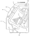
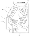
次に、図11及び図12を参照して、ドップラーセンサ11の洗濯乾燥機1に対する設置箇所の一例について説明する。図11及び図12は、いずれも、洗濯乾燥機1の一例であるドラム式洗濯乾燥機1の模式的な縦断面図である。
次に、図11及び図12を参照して、ドップラーセンサ11の洗濯乾燥機1に対する設置箇所の一例について説明する。図11及び図12は、いずれも、洗濯乾燥機1の一例であるドラム式洗濯乾燥機1の模式的な縦断面図である。
図11及び図12に例示するドラム式洗濯乾燥機1は、所謂「斜めドラム」式の洗濯乾燥機1である。図11及び図12に例示するように、ドラム式洗濯乾燥機1は、本体である筐体2と、筐体2内に設けられた洗濯乾燥槽の一例であるドラム3と、を備えてよい。
ドラム3は、ドラム回転軸8に取り付けられて筐体2内でドラム回転軸8を中心に回転自在である。ドラム回転軸8は、例示的に、図1及び図3に例示したモータ133によって回転駆動されてよい。モータ133は、順方向及び逆方向の双方向に回転可能であってよい。
ドラム3は、例示的に、筐体2の底面2aに対して斜め(例えば、約45度)上方に開口部3aが向くように配置されてよい。別言すると、ドラム回転軸8が筐体2の底面2aに対して斜め上方に約45度の角度を成すように、筐体2内にドラム3が設置されてよい。
ドラム3の開口部3aが向く方向に、洗濯乾燥機1の開閉扉(ドア)4が筐体2に設けられてよい。ドア4を開いた状態で、ドラム3の開口部3aを通じて、洗濯又は乾燥の対象である洗濯物がドラム3内に収容される。
また、筐体2内には、例示的に、給水パイプ5、排水パイプ6、及び、送風パイプ7が備えられてよい。給水パイプ5は、洗濯乾燥機1内の給水路を形成する。給水パイプ5に、図1及び図3に例示した給水弁135が設けられてよい。給水弁135が開状態に制御されると、給水パイプ5を通じてドラム3への給水が行なわれる。
排水パイプ6は、洗濯乾燥機1内の排水路を形成する。排水パイプ6には、図1及び図3に例示した排水弁134が設けられてよい。排水弁134が開状態に制御されると、排水パイプ6を通じてドラム3からの排水が行なわれる。
送風パイプ7は、洗濯乾燥機1内の送風路を形成する。送風パイプ7には、例示的に、乾燥運転時に、図1及び図3に例示したファン131及びヒータ132によって生成された温風が流れてよい。温風は、送風パイプ7の一方の開口からドラム3内の空間へ供給された後、送風パイプ7の他方の開口を経由してドラム3内の空間へ再び送り出されてよい。別言すると、温風は、ドラム3内の空間と送風パイプ7とを循環してよい。
「斜めドラム」式の洗濯乾燥機1では、ドップラーセンサ11は、非限定的な一例として、電波がドラム3の底面中心付近から洗濯物が重力によって集まり易いドラム3内の側面に向けて照射される位置に設置されてよい。
例えば図11に模式的に示すように、ドラム3の底面中心に部分的に突出したドラム回転軸8に、電波の照射方向が洗濯物の集まり易い、ドラム3内の側壁に向くように、ドップラーセンサ11が設置されてよい。なお、図11において網がけを付して示す領域又は範囲は、ドップラーセンサ11による電波の照射領域又は照射範囲を模式的に示している。
図11の例において、ドップラーセンサ11は、ドラム3が回転しても非回転でドップラーセンサ11を支持可能な構造あるいは部材によってドラム回転軸に取り付けられてよい。ドップラーセンサ11は、照射する電波を透過できる材質のカバーで覆われてもよい。
ドップラーセンサ11が取り付けられるドラム回転軸8は、例示的に、中空構造を有していてよい。中空構造の中空部分に、ドップラーセンサ11とコントローラ12とを電気的に接続する配線が設けられてよい。中空部分に、配線を設けることで、ドラム3の回転によって配線がねじれたり絡まったりすることを防止できる。
また、ドップラーセンサ11をドラム回転軸8に取り付けることで、ドラム3回転時の洗濯乾燥機1の振動がドップラーセンサ11に伝わることによる影響を抑制あるいは緩和できる。
例えば、洗濯乾燥機1の振動がドップラーセンサ11で受信される反射波に与える影響を抑制あるいは緩和できる。したがって、ドップラーセンサ11を用いた、伸展時波長に基づく洗濯物の乾き度判定の精度が低下することを抑制できる。
また、ドップラーセンサ11は、図11に模式的に例示するように、ドラム回転軸8から斜め下方に向けて電波が照射されるように、電波の照射方向が設定されてよい。ドップラーセンサ11の電波照射方向を斜め下方に設定すると、電波がドア4を通り抜けて洗濯乾燥機1の外部に漏れることを抑制あるいは緩和できる。
例えば、洗濯乾燥機1のドア4には、洗濯運転や乾燥運転の状態を外部から視認できるように、透明な強化プラスチック製の「のぞき窓」が設けられることがある。ドップラーセンサ11の送信電波が、「のぞき窓」を通じて洗濯乾燥機1の外部に漏れると、例えば、「のぞき窓」から内部の様子を覗く人物の動き等が、ドップラーセンサ11の受信反射波の変化として現われてしまう。
そのため、図11に例示するように、ドラム回転軸8から洗濯乾燥機1のドア4に向かう方向を避けた方向に向けて電波が送信されるように、ドップラーセンサ11の電波照射方向(「指向性」と称してもよい。)が設定されてよい。
当該電波照射方向の設定により、洗濯乾燥機1内のドップラーセンサ11が受信する反射波に、洗濯乾燥機1外部の人物や物体の動きが影響することを抑制あるいは緩和できる。したがって、ドップラーセンサ11を用いた、伸展時波長に基づく洗濯物の乾き度判定の精度が低下することを抑制できる。
ドップラーセンサ11の設置箇所の他の非限定的な一例は、洗濯乾燥機1のドア4側である。例えば図12に示すように、洗濯乾燥機1のドア4側から、洗濯物が重力によって集まりやすいドラム3の側壁に向けて、電波が照射される位置に、ドップラーセンサ11が設置されてもよい。
例えば、ドア4の軸受け又はその近傍に、電波の照射方向が洗濯物の集まりやすい、ドラム3の側壁に向くように、ドップラーセンサ11が取り付けられてよい。ただし、ドア4そのものに、ドップラーセンサ11が取り付けられてもよい。なお、図12において網がけを付して示す領域又は範囲が、ドップラーセンサ11による電波の照射領域又は照射範囲を模式的に示している。
図12に模式的に例示するように、ドア4側からドラム3内の空間に向けて電波を照射することで、洗濯乾燥機1のドア4側(例えば、既述の「のぞき窓」)から電波が漏れることを抑制あるいは緩和できる。
洗濯乾燥機1のドア4側から電波が漏れにくくなることで、洗濯乾燥機1外部の人物や物体の動きがあっても、ドップラーセンサ11が受信する反射波に、その動きが影響することを抑制あるいは緩和できる。したがって、ドップラーセンサ11を用いた、伸展時波長に基づく洗濯物の乾き度判定の精度が低下することを抑制できる。
なお、図12に例示するようにドップラーセンサ11をドア4側に取り付けると、図11の例のようにドップラーセンサ11をドラム回転軸8に取り付ける場合よりも、ドラム回転時の振動の影響をドップラーセンサ11が受けやすい、と云える。
しかし、ドラム回転時の振動に応じて、ドップラーセンサ11の受信する反射波の信号波形に変化が生じたとしても、振動数が一定の期間において「伸展時波長」が安定的に収束すれば、「洗濯物が乾いた」と判定してよい。別言すると、「伸展時波長」には、洗濯乾燥機1の振動に応じた反射波の変化を示す情報が含まれている、と捉えてもよい。
振動数が一定でない期間では、既述の変形例と同様にして「伸展時波長の補正」を行なってよい。例えば、振動数の変化は、ドラム回転数の変化に依存すると捉えてよければ、ドラム回転数の変化に応じて、「伸展時波長」に加算する振幅変化量を選定、除外してよい。
また、乾燥運転の開始直後から暫くの間は、洗濯乾燥機1の振動数が安定しないことが想定される。したがって、乾燥運転の開始に応じてドップラーセンサ11による電波の送信を開始させてから所定時間は、コントローラ12において「伸展時波長」の算出は待機するようにしてもよい。
例えば、コントローラ12は、ドップラーセンサ11による電波の送信開始から数秒~数十秒の間を待ってから、「伸展時波長」の算出を開始するようにしてもよい。これにより、「伸展時波長」を算出しても、その信頼度が低いと考えられる時間に、無駄に「伸展時波長」が算出されることを回避できる。したがって、例えば、コントローラ12の消費電力の低減を図ることができ、ひいては、洗濯乾燥機1の省エネ化に寄与する。
なお、洗濯物の乾き度は、洗濯乾燥機1の庫内温度や吸排気温度の変化を温度センサにより検出して、その変化点や変化率を基に推定したり、光学式センサを用いて光の吸収量の変化を基に推定したりすることも考えられる。
しかし、温度センサを用いた推定では、乾燥運転時にヒータ温度が一定に制御されることが前提であり、ヒータ温度が制御されると乾き度の推定精度が大きく低下する。また、光学式センサを用いた推定では、洗濯乾燥機1内には水分やほこり等が付着しやすいため、光学式センサの発光面や受光面に水分やほこり等が付着して、センシング感度が低下しやすい。
これに対し、上述したドップラーセンサ11を用いた乾き度の検出方法によれば、洗濯乾燥機1内の温度変化や、水分やほこり等の汚れによる影響を受けないか、受けにくい。別言すると、ドップラーセンサ11は、温度センサや光学式センサに比して、洗濯乾燥機1内の環境変化に対する耐性が高い。そのため、乾き度の検出精度の向上、ひいては、乾燥運転の効率化を図ることができる。
(その他)
上述した変形例を含む実施形態では、洗濯乾燥機1に対して1つのドップラーセンサ11を設ける例について説明したが、複数のドップラーセンサ11が、洗濯乾燥機1に設けられてもよい。例えば、図11及び図12に例示した、ドラム回転軸8及びドア4側の双方にドップラーセンサ11が備えられてもよい。
上述した変形例を含む実施形態では、洗濯乾燥機1に対して1つのドップラーセンサ11を設ける例について説明したが、複数のドップラーセンサ11が、洗濯乾燥機1に設けられてもよい。例えば、図11及び図12に例示した、ドラム回転軸8及びドア4側の双方にドップラーセンサ11が備えられてもよい。
コントローラ12の例えば信号演算部121は、複数のドップラーセンサ11で得られるビート信号を平均化して、あるいは、例えば設置箇所に応じた重み付けを施して、「伸展時波長」を算出してよい。
また、上述した変形例を含む実施形態では、洗濯乾燥機1のドラム3内での洗濯物の乾燥状態を検出して、その検出結果を基に洗濯乾燥機1の乾燥運転を制御(例えば、停止)する例について説明した。別言すると、ドップラーセンサ11を用いた乾き度検出装置による検出結果を、洗濯乾燥機1の乾燥運転の制御に連携させる例について説明した。
しかし、ドップラーセンサ11を用いた乾き度検出装置は、例えば、浴室乾燥機に備えられてもよい。この場合、乾き度検出装置による、浴室内の空間内での洗濯物の乾燥状態の検出結果は、浴室乾燥機の乾燥運転の制御(例えば、除湿機や換気扇等の制御)に連携させてよい。
また、ドップラーセンサ11を用いた乾き度検出装置は、乾燥処理において動きが生じ得る乾燥対象物の乾き度(あるいは濡れ度)の検出に広く適用でき、その検出結果を制御に利用する装置や製品に広く適用あるいは応用できる。なお、「乾き度検出装置」は、「乾き度測定装置」あるいは「乾き度判定装置」と称してもよいし、「乾き度センサ」と称してもよい。
1 洗濯乾燥機
2 本体(筐体)
2a 底面
3 ドラム(洗濯乾燥槽)
3a 開口部
4 開閉扉(ドア)
5 給水パイプ
6 排水パイプ
7 送風パイプ
8 ドラム回転軸
11 ドップラーセンサ
111 アンテナ
112 ローカル発振器(Oscillator, OSC)
113 MCU(Micro Control Unit)
114 検波回路
115 オペアンプ(OP)
116 バッテリ
12 コントローラ
121 信号演算部 122 判定部
123 データベース(DB)
124 モード制御部
13 駆動機構
131 ファン
132 ヒータ
133 モータ
134 排水弁
135 給水弁
21 プロセッサ
22 メモリ
23 入出力インタフェース(IF)
24 バス
141 操作部
142 水位センサ
143 温度センサ
144 湿度センサ
145 扉開閉センサ
146 質量センサ
147 回転数センサ
2 本体(筐体)
2a 底面
3 ドラム(洗濯乾燥槽)
3a 開口部
4 開閉扉(ドア)
5 給水パイプ
6 排水パイプ
7 送風パイプ
8 ドラム回転軸
11 ドップラーセンサ
111 アンテナ
112 ローカル発振器(Oscillator, OSC)
113 MCU(Micro Control Unit)
114 検波回路
115 オペアンプ(OP)
116 バッテリ
12 コントローラ
121 信号演算部 122 判定部
123 データベース(DB)
124 モード制御部
13 駆動機構
131 ファン
132 ヒータ
133 モータ
134 排水弁
135 給水弁
21 プロセッサ
22 メモリ
23 入出力インタフェース(IF)
24 バス
141 操作部
142 水位センサ
143 温度センサ
144 湿度センサ
145 扉開閉センサ
146 質量センサ
147 回転数センサ
Claims (15)
- 乾燥の対象物が収容される空間内に電波を送信するドップラーセンサと、
洗濯処理に応じた動作から乾燥処理に応じた動作への切り替わりに応じて、前記ドップラーセンサに電波の送信を開始させ、前記ドップラーセンサが受信した反射波に応じて、前記乾燥処理の動作を制御する制御部と、
を備えた、洗濯乾燥機。 - 前記乾燥処理の動作の制御は、前記乾燥処理の動作を停止する制御を含む、請求項1記載の洗濯乾燥機。
- 前記乾燥処理の動作の制御は、前記空間への空気の流入制御を含む、請求項1記載の洗濯乾燥機。
- 前記空間は、前記洗濯乾燥機のドラム内の空間である、請求項1記載の洗濯乾燥機。
- 前記乾燥処理の動作を停止するタイミングは、前記反射波の振幅と周波数とに基づいて決定される、請求項2に記載の洗濯乾燥機。
- 前記決定は、前記反射波の振幅と周波数とを基に算出される、単位時間あたりに前記振幅の変化が時間領域で描く軌跡に相当する信号波形の長さが、一定値又は一定範囲内に収束することに応じてなされる、請求項5に記載の洗濯乾燥機。
- 前記信号波形の長さの算出は、前記電波の送信の開始後の所定時間を待機してから、開始される、請求項6に記載の洗濯乾燥機。
- 前記ドップラーセンサは、前記洗濯乾燥機のドラムの回転軸に取り付けられた、請求項1~7のいずれか1項に記載の洗濯乾燥機。
- 前記ドップラーセンサは、前記回転軸から前記洗濯乾燥機の開閉扉に向かう方向を避けた方向に向けて前記電波が送信されるように、前記電波の送信方向が設定された、請求項8に記載の洗濯乾燥機。
- 前記ドップラーセンサは、前記洗濯乾燥機の開閉扉の側に取り付けられた、請求項1~7のいずれか1項に記載の洗濯乾燥機。
- 前記乾燥の対象物は、洗濯物であり、
前記ドップラーセンサは、前記洗濯乾燥機のドラム内で前記洗濯物が重力によって集まりやすい位置に向けて前記電波が送信されるように、前記電波の送信方向が設定された、請求項8~10のいずれか1項に記載の洗濯乾燥機。 - 洗濯乾燥機の洗濯処理に応じた動作から乾燥処理に応じた動作への切り替わりに応じて、前記乾燥処理による乾燥の対象物が収容される空間内に電波を送信するドップラーセンサに、前記電波の送信を開始させ、前記ドップラーセンサが受信した反射波に応じて、前記乾燥処理の動作を制御する制御部を備えた、洗濯乾燥機の制御装置。
- 乾燥対象物が収容される空間内に電波を送信するドップラーセンサと、
前記電波の送信に応じて前記ドップラーセンサが受信した反射波の振幅及び周波数に基づいて、前記乾燥対象物の乾き度を検出する検出部と、
を備えた、乾き度検出装置。 - 前記検出部は、
前記反射波の振幅及び周波数に基づいて、単位時間あたりに前記振幅の変化が時間領域で描く軌跡に相当する信号波形の長さを求める信号演算部と、
前記信号波形の長さが一定値又は一定範囲内に収束すると、前記乾燥対象物が乾燥したと判定する判定部と、を備えた、請求項13に記載の乾き度検出装置。 - 乾燥対象物が収容される空間内に電波を送信するドップラーセンサと、
前記電波の送信に応じて前記ドップラーセンサが受信した反射波の振幅及び周波数に基づいて、前記乾燥対象物の乾き度を検出する検出部と、
前記検出部によって検出された乾き度に応じて、前記乾燥対象物の乾燥処理を制御する制御部と、
を備えた、乾燥機。
Applications Claiming Priority (2)
| Application Number | Priority Date | Filing Date | Title |
|---|---|---|---|
| JP2015045478A JP2016165328A (ja) | 2015-03-09 | 2015-03-09 | 洗濯乾燥機、洗濯乾燥機の制御装置、乾き度検出装置、及び、乾燥機 |
| JP2015-045478 | 2015-03-09 |
Publications (1)
| Publication Number | Publication Date |
|---|---|
| WO2016143596A1 true WO2016143596A1 (ja) | 2016-09-15 |
Family
ID=56879470
Family Applications (1)
| Application Number | Title | Priority Date | Filing Date |
|---|---|---|---|
| PCT/JP2016/056176 Ceased WO2016143596A1 (ja) | 2015-03-09 | 2016-03-01 | 洗濯乾燥機、洗濯乾燥機の制御装置、乾き度検出装置、及び、乾燥機 |
Country Status (2)
| Country | Link |
|---|---|
| JP (1) | JP2016165328A (ja) |
| WO (1) | WO2016143596A1 (ja) |
Families Citing this family (2)
| Publication number | Priority date | Publication date | Assignee | Title |
|---|---|---|---|---|
| JP7496054B2 (ja) * | 2020-07-22 | 2024-06-06 | 株式会社ノーリツ | 浴室暖房乾燥機 |
| JP7671141B2 (ja) * | 2020-12-17 | 2025-05-01 | 東芝ライフスタイル株式会社 | 乾燥システム |
Citations (3)
| Publication number | Priority date | Publication date | Assignee | Title |
|---|---|---|---|---|
| JPH02249958A (ja) * | 1989-03-24 | 1990-10-05 | Hiroshi Azuma | 物体中に含まれる水分量の計測方法及びその計測装置 |
| EP1321565A1 (de) * | 2001-12-21 | 2003-06-25 | BSH Bosch und Siemens Hausgeräte GmbH | Wäschepflegeeinrichtung mit Feuchtsensor und Verfahren zur Messung der Feuchte in einer Wäschepflegeeinrichtung |
| JP2014018608A (ja) * | 2012-07-24 | 2014-02-03 | Panasonic Corp | 衣類乾燥機 |
-
2015
- 2015-03-09 JP JP2015045478A patent/JP2016165328A/ja active Pending
-
2016
- 2016-03-01 WO PCT/JP2016/056176 patent/WO2016143596A1/ja not_active Ceased
Patent Citations (3)
| Publication number | Priority date | Publication date | Assignee | Title |
|---|---|---|---|---|
| JPH02249958A (ja) * | 1989-03-24 | 1990-10-05 | Hiroshi Azuma | 物体中に含まれる水分量の計測方法及びその計測装置 |
| EP1321565A1 (de) * | 2001-12-21 | 2003-06-25 | BSH Bosch und Siemens Hausgeräte GmbH | Wäschepflegeeinrichtung mit Feuchtsensor und Verfahren zur Messung der Feuchte in einer Wäschepflegeeinrichtung |
| JP2014018608A (ja) * | 2012-07-24 | 2014-02-03 | Panasonic Corp | 衣類乾燥機 |
Also Published As
| Publication number | Publication date |
|---|---|
| JP2016165328A (ja) | 2016-09-15 |
Similar Documents
| Publication | Publication Date | Title |
|---|---|---|
| CN106574418B (zh) | 控制洗衣机的方法 | |
| CN101688354B (zh) | 控制滚筒式干衣机的方法 | |
| JP7257632B2 (ja) | 乾燥機、制御装置、及び制御プログラム | |
| US11821125B2 (en) | Laundry treating apparatus and sanitation managing method for laundry using the same | |
| US20160053427A1 (en) | Clothes dryer wireless moisture data transfer systems and energy-efficient methods of operation | |
| JP2011239990A (ja) | 乾燥機 | |
| US20220002932A1 (en) | Method and device for an air-guiding domestic appliance | |
| WO2013088830A1 (ja) | 衣類乾燥機 | |
| WO2020080365A1 (ja) | 乾燥機、制御装置、制御プログラム、および乾燥機の制御方法 | |
| US20160201253A1 (en) | Recharging of nfc system and algorithms to conserve power supply of nfc system designed for clothes dryer | |
| CN114717824A (zh) | 衣物处理装置的控制方法及衣物处理装置 | |
| US6928749B2 (en) | Laundry dryer | |
| WO2016143596A1 (ja) | 洗濯乾燥機、洗濯乾燥機の制御装置、乾き度検出装置、及び、乾燥機 | |
| JP6571921B2 (ja) | 洗濯機 | |
| US20170037563A1 (en) | Dryer appliances and methods for operating dryer appliances utilizing wireless moisture data transfer systems | |
| JPH119897A (ja) | 衣類乾燥度判断方法及び衣類乾燥機 | |
| JP7352888B2 (ja) | 乾燥機、制御装置、及び制御プログラム | |
| US20250257510A1 (en) | Clothes treatment apparatus and method of controlling the same | |
| WO2020007229A1 (zh) | 衣物处理设备及其衣物温度控制方法 | |
| JP6493720B2 (ja) | 衣類乾燥機 | |
| US12467178B2 (en) | Washing machine and control method thereof | |
| US20260043565A1 (en) | Controlled humidity release system | |
| KR101711836B1 (ko) | 세탁기의 동결 관리 시스템 | |
| JP2019188251A (ja) | 洗濯機 | |
| JP2010240181A (ja) | 乾燥装置、同装置の制御方法、およびプログラム |
Legal Events
| Date | Code | Title | Description |
|---|---|---|---|
| 121 | Ep: the epo has been informed by wipo that ep was designated in this application |
Ref document number: 16761566 Country of ref document: EP Kind code of ref document: A1 |
|
| NENP | Non-entry into the national phase |
Ref country code: DE |
|
| 122 | Ep: pct application non-entry in european phase |
Ref document number: 16761566 Country of ref document: EP Kind code of ref document: A1 |