WO2016143521A1 - 接合構造体の製造方法および接合構造体 - Google Patents
接合構造体の製造方法および接合構造体 Download PDFInfo
- Publication number
- WO2016143521A1 WO2016143521A1 PCT/JP2016/055468 JP2016055468W WO2016143521A1 WO 2016143521 A1 WO2016143521 A1 WO 2016143521A1 JP 2016055468 W JP2016055468 W JP 2016055468W WO 2016143521 A1 WO2016143521 A1 WO 2016143521A1
- Authority
- WO
- WIPO (PCT)
- Prior art keywords
- sub
- pulse
- laser
- peak output
- metal member
- Prior art date
- Legal status (The legal status is an assumption and is not a legal conclusion. Google has not performed a legal analysis and makes no representation as to the accuracy of the status listed.)
- Ceased
Links
Images

Classifications
-
- B—PERFORMING OPERATIONS; TRANSPORTING
- B29—WORKING OF PLASTICS; WORKING OF SUBSTANCES IN A PLASTIC STATE IN GENERAL
- B29C—SHAPING OR JOINING OF PLASTICS; SHAPING OF MATERIAL IN A PLASTIC STATE, NOT OTHERWISE PROVIDED FOR; AFTER-TREATMENT OF THE SHAPED PRODUCTS, e.g. REPAIRING
- B29C65/00—Joining or sealing of preformed parts, e.g. welding of plastics materials; Apparatus therefor
- B29C65/02—Joining or sealing of preformed parts, e.g. welding of plastics materials; Apparatus therefor by heating, with or without pressure
- B29C65/14—Joining or sealing of preformed parts, e.g. welding of plastics materials; Apparatus therefor by heating, with or without pressure using wave energy, i.e. electromagnetic radiation, or particle radiation
- B29C65/16—Laser beams
- B29C65/1629—Laser beams characterised by the way of heating the interface
- B29C65/1635—Laser beams characterised by the way of heating the interface at least passing through one of the parts to be joined, i.e. laser transmission welding
-
- B—PERFORMING OPERATIONS; TRANSPORTING
- B23—MACHINE TOOLS; METAL-WORKING NOT OTHERWISE PROVIDED FOR
- B23K—SOLDERING OR UNSOLDERING; WELDING; CLADDING OR PLATING BY SOLDERING OR WELDING; CUTTING BY APPLYING HEAT LOCALLY, e.g. FLAME CUTTING; WORKING BY LASER BEAM
- B23K26/00—Working by laser beam, e.g. welding, cutting or boring
- B23K26/02—Positioning or observing the workpiece, e.g. with respect to the point of impact; Aligning, aiming or focusing the laser beam
- B23K26/06—Shaping the laser beam, e.g. by masks or multi-focusing
- B23K26/062—Shaping the laser beam, e.g. by masks or multi-focusing by direct control of the laser beam
- B23K26/0622—Shaping the laser beam, e.g. by masks or multi-focusing by direct control of the laser beam by shaping pulses
-
- B—PERFORMING OPERATIONS; TRANSPORTING
- B23—MACHINE TOOLS; METAL-WORKING NOT OTHERWISE PROVIDED FOR
- B23K—SOLDERING OR UNSOLDERING; WELDING; CLADDING OR PLATING BY SOLDERING OR WELDING; CUTTING BY APPLYING HEAT LOCALLY, e.g. FLAME CUTTING; WORKING BY LASER BEAM
- B23K26/00—Working by laser beam, e.g. welding, cutting or boring
- B23K26/20—Bonding
- B23K26/32—Bonding taking account of the properties of the material involved
- B23K26/324—Bonding taking account of the properties of the material involved involving non-metallic parts
-
- B—PERFORMING OPERATIONS; TRANSPORTING
- B23—MACHINE TOOLS; METAL-WORKING NOT OTHERWISE PROVIDED FOR
- B23K—SOLDERING OR UNSOLDERING; WELDING; CLADDING OR PLATING BY SOLDERING OR WELDING; CUTTING BY APPLYING HEAT LOCALLY, e.g. FLAME CUTTING; WORKING BY LASER BEAM
- B23K26/00—Working by laser beam, e.g. welding, cutting or boring
- B23K26/36—Removing material
- B23K26/38—Removing material by boring or cutting
- B23K26/382—Removing material by boring or cutting by boring
- B23K26/384—Removing material by boring or cutting by boring of specially shaped holes
-
- B—PERFORMING OPERATIONS; TRANSPORTING
- B29—WORKING OF PLASTICS; WORKING OF SUBSTANCES IN A PLASTIC STATE IN GENERAL
- B29C—SHAPING OR JOINING OF PLASTICS; SHAPING OF MATERIAL IN A PLASTIC STATE, NOT OTHERWISE PROVIDED FOR; AFTER-TREATMENT OF THE SHAPED PRODUCTS, e.g. REPAIRING
- B29C65/00—Joining or sealing of preformed parts, e.g. welding of plastics materials; Apparatus therefor
- B29C65/02—Joining or sealing of preformed parts, e.g. welding of plastics materials; Apparatus therefor by heating, with or without pressure
- B29C65/14—Joining or sealing of preformed parts, e.g. welding of plastics materials; Apparatus therefor by heating, with or without pressure using wave energy, i.e. electromagnetic radiation, or particle radiation
- B29C65/16—Laser beams
-
- B—PERFORMING OPERATIONS; TRANSPORTING
- B29—WORKING OF PLASTICS; WORKING OF SUBSTANCES IN A PLASTIC STATE IN GENERAL
- B29C—SHAPING OR JOINING OF PLASTICS; SHAPING OF MATERIAL IN A PLASTIC STATE, NOT OTHERWISE PROVIDED FOR; AFTER-TREATMENT OF THE SHAPED PRODUCTS, e.g. REPAIRING
- B29C66/00—General aspects of processes or apparatus for joining preformed parts
- B29C66/01—General aspects dealing with the joint area or with the area to be joined
- B29C66/02—Preparation of the material, in the area to be joined, prior to joining or welding
- B29C66/024—Thermal pre-treatments
- B29C66/0246—Cutting or perforating, e.g. burning away by using a laser or using hot air
-
- B—PERFORMING OPERATIONS; TRANSPORTING
- B29—WORKING OF PLASTICS; WORKING OF SUBSTANCES IN A PLASTIC STATE IN GENERAL
- B29C—SHAPING OR JOINING OF PLASTICS; SHAPING OF MATERIAL IN A PLASTIC STATE, NOT OTHERWISE PROVIDED FOR; AFTER-TREATMENT OF THE SHAPED PRODUCTS, e.g. REPAIRING
- B29C66/00—General aspects of processes or apparatus for joining preformed parts
- B29C66/01—General aspects dealing with the joint area or with the area to be joined
- B29C66/05—Particular design of joint configurations
- B29C66/10—Particular design of joint configurations particular design of the joint cross-sections
- B29C66/11—Joint cross-sections comprising a single joint-segment, i.e. one of the parts to be joined comprising a single joint-segment in the joint cross-section
- B29C66/112—Single lapped joints
- B29C66/1122—Single lap to lap joints, i.e. overlap joints
-
- B—PERFORMING OPERATIONS; TRANSPORTING
- B29—WORKING OF PLASTICS; WORKING OF SUBSTANCES IN A PLASTIC STATE IN GENERAL
- B29C—SHAPING OR JOINING OF PLASTICS; SHAPING OF MATERIAL IN A PLASTIC STATE, NOT OTHERWISE PROVIDED FOR; AFTER-TREATMENT OF THE SHAPED PRODUCTS, e.g. REPAIRING
- B29C66/00—General aspects of processes or apparatus for joining preformed parts
- B29C66/01—General aspects dealing with the joint area or with the area to be joined
- B29C66/05—Particular design of joint configurations
- B29C66/303—Particular design of joint configurations the joint involving an anchoring effect
- B29C66/3032—Particular design of joint configurations the joint involving an anchoring effect making use of protrusions or cavities belonging to at least one of the parts to be joined
- B29C66/30325—Particular design of joint configurations the joint involving an anchoring effect making use of protrusions or cavities belonging to at least one of the parts to be joined making use of cavities belonging to at least one of the parts to be joined
-
- B—PERFORMING OPERATIONS; TRANSPORTING
- B29—WORKING OF PLASTICS; WORKING OF SUBSTANCES IN A PLASTIC STATE IN GENERAL
- B29C—SHAPING OR JOINING OF PLASTICS; SHAPING OF MATERIAL IN A PLASTIC STATE, NOT OTHERWISE PROVIDED FOR; AFTER-TREATMENT OF THE SHAPED PRODUCTS, e.g. REPAIRING
- B29C66/00—General aspects of processes or apparatus for joining preformed parts
- B29C66/70—General aspects of processes or apparatus for joining preformed parts characterised by the composition, physical properties or the structure of the material of the parts to be joined; Joining with non-plastics material
- B29C66/74—Joining plastics material to non-plastics material
- B29C66/742—Joining plastics material to non-plastics material to metals or their alloys
-
- B—PERFORMING OPERATIONS; TRANSPORTING
- B29—WORKING OF PLASTICS; WORKING OF SUBSTANCES IN A PLASTIC STATE IN GENERAL
- B29C—SHAPING OR JOINING OF PLASTICS; SHAPING OF MATERIAL IN A PLASTIC STATE, NOT OTHERWISE PROVIDED FOR; AFTER-TREATMENT OF THE SHAPED PRODUCTS, e.g. REPAIRING
- B29C66/00—General aspects of processes or apparatus for joining preformed parts
- B29C66/70—General aspects of processes or apparatus for joining preformed parts characterised by the composition, physical properties or the structure of the material of the parts to be joined; Joining with non-plastics material
- B29C66/71—General aspects of processes or apparatus for joining preformed parts characterised by the composition, physical properties or the structure of the material of the parts to be joined; Joining with non-plastics material characterised by the composition of the plastics material of the parts to be joined
-
- B—PERFORMING OPERATIONS; TRANSPORTING
- B29—WORKING OF PLASTICS; WORKING OF SUBSTANCES IN A PLASTIC STATE IN GENERAL
- B29C—SHAPING OR JOINING OF PLASTICS; SHAPING OF MATERIAL IN A PLASTIC STATE, NOT OTHERWISE PROVIDED FOR; AFTER-TREATMENT OF THE SHAPED PRODUCTS, e.g. REPAIRING
- B29C66/00—General aspects of processes or apparatus for joining preformed parts
- B29C66/70—General aspects of processes or apparatus for joining preformed parts characterised by the composition, physical properties or the structure of the material of the parts to be joined; Joining with non-plastics material
- B29C66/72—General aspects of processes or apparatus for joining preformed parts characterised by the composition, physical properties or the structure of the material of the parts to be joined; Joining with non-plastics material characterised by the structure of the material of the parts to be joined
- B29C66/721—Fibre-reinforced materials
-
- B—PERFORMING OPERATIONS; TRANSPORTING
- B29—WORKING OF PLASTICS; WORKING OF SUBSTANCES IN A PLASTIC STATE IN GENERAL
- B29C—SHAPING OR JOINING OF PLASTICS; SHAPING OF MATERIAL IN A PLASTIC STATE, NOT OTHERWISE PROVIDED FOR; AFTER-TREATMENT OF THE SHAPED PRODUCTS, e.g. REPAIRING
- B29C66/00—General aspects of processes or apparatus for joining preformed parts
- B29C66/70—General aspects of processes or apparatus for joining preformed parts characterised by the composition, physical properties or the structure of the material of the parts to be joined; Joining with non-plastics material
- B29C66/72—General aspects of processes or apparatus for joining preformed parts characterised by the composition, physical properties or the structure of the material of the parts to be joined; Joining with non-plastics material characterised by the structure of the material of the parts to be joined
- B29C66/721—Fibre-reinforced materials
- B29C66/7212—Fibre-reinforced materials characterised by the composition of the fibres
-
- B—PERFORMING OPERATIONS; TRANSPORTING
- B29—WORKING OF PLASTICS; WORKING OF SUBSTANCES IN A PLASTIC STATE IN GENERAL
- B29C—SHAPING OR JOINING OF PLASTICS; SHAPING OF MATERIAL IN A PLASTIC STATE, NOT OTHERWISE PROVIDED FOR; AFTER-TREATMENT OF THE SHAPED PRODUCTS, e.g. REPAIRING
- B29C66/00—General aspects of processes or apparatus for joining preformed parts
- B29C66/70—General aspects of processes or apparatus for joining preformed parts characterised by the composition, physical properties or the structure of the material of the parts to be joined; Joining with non-plastics material
- B29C66/73—General aspects of processes or apparatus for joining preformed parts characterised by the composition, physical properties or the structure of the material of the parts to be joined; Joining with non-plastics material characterised by the intensive physical properties of the material of the parts to be joined, by the optical properties of the material of the parts to be joined, by the extensive physical properties of the parts to be joined, by the state of the material of the parts to be joined or by the material of the parts to be joined being a thermoplastic or a thermoset
- B29C66/739—General aspects of processes or apparatus for joining preformed parts characterised by the composition, physical properties or the structure of the material of the parts to be joined; Joining with non-plastics material characterised by the intensive physical properties of the material of the parts to be joined, by the optical properties of the material of the parts to be joined, by the extensive physical properties of the parts to be joined, by the state of the material of the parts to be joined or by the material of the parts to be joined being a thermoplastic or a thermoset characterised by the material of the parts to be joined being a thermoplastic or a thermoset
- B29C66/7392—General aspects of processes or apparatus for joining preformed parts characterised by the composition, physical properties or the structure of the material of the parts to be joined; Joining with non-plastics material characterised by the intensive physical properties of the material of the parts to be joined, by the optical properties of the material of the parts to be joined, by the extensive physical properties of the parts to be joined, by the state of the material of the parts to be joined or by the material of the parts to be joined being a thermoplastic or a thermoset characterised by the material of the parts to be joined being a thermoplastic or a thermoset characterised by the material of at least one of the parts being a thermoplastic
-
- B—PERFORMING OPERATIONS; TRANSPORTING
- B29—WORKING OF PLASTICS; WORKING OF SUBSTANCES IN A PLASTIC STATE IN GENERAL
- B29C—SHAPING OR JOINING OF PLASTICS; SHAPING OF MATERIAL IN A PLASTIC STATE, NOT OTHERWISE PROVIDED FOR; AFTER-TREATMENT OF THE SHAPED PRODUCTS, e.g. REPAIRING
- B29C66/00—General aspects of processes or apparatus for joining preformed parts
- B29C66/70—General aspects of processes or apparatus for joining preformed parts characterised by the composition, physical properties or the structure of the material of the parts to be joined; Joining with non-plastics material
- B29C66/73—General aspects of processes or apparatus for joining preformed parts characterised by the composition, physical properties or the structure of the material of the parts to be joined; Joining with non-plastics material characterised by the intensive physical properties of the material of the parts to be joined, by the optical properties of the material of the parts to be joined, by the extensive physical properties of the parts to be joined, by the state of the material of the parts to be joined or by the material of the parts to be joined being a thermoplastic or a thermoset
- B29C66/739—General aspects of processes or apparatus for joining preformed parts characterised by the composition, physical properties or the structure of the material of the parts to be joined; Joining with non-plastics material characterised by the intensive physical properties of the material of the parts to be joined, by the optical properties of the material of the parts to be joined, by the extensive physical properties of the parts to be joined, by the state of the material of the parts to be joined or by the material of the parts to be joined being a thermoplastic or a thermoset characterised by the material of the parts to be joined being a thermoplastic or a thermoset
- B29C66/7394—General aspects of processes or apparatus for joining preformed parts characterised by the composition, physical properties or the structure of the material of the parts to be joined; Joining with non-plastics material characterised by the intensive physical properties of the material of the parts to be joined, by the optical properties of the material of the parts to be joined, by the extensive physical properties of the parts to be joined, by the state of the material of the parts to be joined or by the material of the parts to be joined being a thermoplastic or a thermoset characterised by the material of the parts to be joined being a thermoplastic or a thermoset characterised by the material of at least one of the parts being a thermoset
-
- B—PERFORMING OPERATIONS; TRANSPORTING
- B29—WORKING OF PLASTICS; WORKING OF SUBSTANCES IN A PLASTIC STATE IN GENERAL
- B29C—SHAPING OR JOINING OF PLASTICS; SHAPING OF MATERIAL IN A PLASTIC STATE, NOT OTHERWISE PROVIDED FOR; AFTER-TREATMENT OF THE SHAPED PRODUCTS, e.g. REPAIRING
- B29C66/00—General aspects of processes or apparatus for joining preformed parts
- B29C66/70—General aspects of processes or apparatus for joining preformed parts characterised by the composition, physical properties or the structure of the material of the parts to be joined; Joining with non-plastics material
- B29C66/74—Joining plastics material to non-plastics material
- B29C66/742—Joining plastics material to non-plastics material to metals or their alloys
- B29C66/7422—Aluminium or alloys of aluminium
-
- B—PERFORMING OPERATIONS; TRANSPORTING
- B29—WORKING OF PLASTICS; WORKING OF SUBSTANCES IN A PLASTIC STATE IN GENERAL
- B29C—SHAPING OR JOINING OF PLASTICS; SHAPING OF MATERIAL IN A PLASTIC STATE, NOT OTHERWISE PROVIDED FOR; AFTER-TREATMENT OF THE SHAPED PRODUCTS, e.g. REPAIRING
- B29C66/00—General aspects of processes or apparatus for joining preformed parts
- B29C66/70—General aspects of processes or apparatus for joining preformed parts characterised by the composition, physical properties or the structure of the material of the parts to be joined; Joining with non-plastics material
- B29C66/74—Joining plastics material to non-plastics material
- B29C66/742—Joining plastics material to non-plastics material to metals or their alloys
- B29C66/7428—Transition metals or their alloys
- B29C66/74281—Copper or alloys of copper
-
- B—PERFORMING OPERATIONS; TRANSPORTING
- B29—WORKING OF PLASTICS; WORKING OF SUBSTANCES IN A PLASTIC STATE IN GENERAL
- B29C—SHAPING OR JOINING OF PLASTICS; SHAPING OF MATERIAL IN A PLASTIC STATE, NOT OTHERWISE PROVIDED FOR; AFTER-TREATMENT OF THE SHAPED PRODUCTS, e.g. REPAIRING
- B29C66/00—General aspects of processes or apparatus for joining preformed parts
- B29C66/70—General aspects of processes or apparatus for joining preformed parts characterised by the composition, physical properties or the structure of the material of the parts to be joined; Joining with non-plastics material
- B29C66/74—Joining plastics material to non-plastics material
- B29C66/742—Joining plastics material to non-plastics material to metals or their alloys
- B29C66/7428—Transition metals or their alloys
- B29C66/74283—Iron or alloys of iron, e.g. steel
-
- B—PERFORMING OPERATIONS; TRANSPORTING
- B29—WORKING OF PLASTICS; WORKING OF SUBSTANCES IN A PLASTIC STATE IN GENERAL
- B29K—INDEXING SCHEME ASSOCIATED WITH SUBCLASSES B29B, B29C OR B29D, RELATING TO MOULDING MATERIALS OR TO MATERIALS FOR MOULDS, REINFORCEMENTS, FILLERS OR PREFORMED PARTS, e.g. INSERTS
- B29K2105/00—Condition, form or state of moulded material or of the material to be shaped
- B29K2105/0079—Liquid crystals
Definitions
- the present invention relates to a method for manufacturing a bonded structure and a bonded structure.
- a joint structure in which a metal member and a resin member are joined is known.
- the joint strength is often increased by the so-called anchor effect generated by filling the perforated part. Therefore, in order to further increase the bonding strength, it is effective to control the shape of the perforated part during laser processing to form a shape that enhances the anchor effect.
- Patent Document 1 discloses a laser processing method for shortening the piercing time by reducing the diameter of the piercing hole and reducing the amount of sputtering. Is disclosed. Specifically, the thing of this patent document 1 is between the 1st process of irradiating a beam on the 1st piercing condition, and the 3rd process of irradiating a beam on the 2nd piercing condition, By providing the second step of temporarily stopping the beam irradiation and the assist gas injection, the oxidation combustion reaction is interrupted to prevent the hole diameter from expanding due to an excessive oxidation combustion reaction.
- the method of irradiating a laser pulse composed of a plurality of sub-pulses makes it easy to concentrate the laser energy in the depth direction, for example, a plurality of sub-pulses in which one pulse has the same peak output and the same pulse width.
- the shape of the perforated part can be controlled by irradiating the surface of the metal member with a laser pulse (hereinafter also referred to as a laser pulse group) configured by adjusting the number of subpulses included in one laser pulse group. Conceivable.
- some metal materials have a high surface reflectance or a high melting point. At the start of drilling in a metal material having such a high surface reflectance or melting point, metal melting is started (the processing threshold is exceeded). ) High peak power is required. Since the laser energy (time integration value of the subpulse) of one laser pulse group is limited by the performance of the laser light source, if the laser pulse group is composed only of subpulses having a high peak output, the subpulses included in the laser pulse group There is a risk that it will be difficult to control the shape of the perforated part.
- the present invention has been made in view of the above points, and an object of the present invention is to form a bonded structure by a laser beam by efficiently using limited laser energy in the manufacturing method of the bonded structure and the bonded structure. It is to provide a technique for controlling the shape of the perforated part.
- the laser pulse group irradiated on the metal member is configured by combining a plurality of sub-pulse trains having different pulse waveforms.
- the present invention relates to a method for manufacturing a bonded structure in which a metal member and a resin member are bonded, and a laser light source capable of repeatedly oscillating a laser pulse group each composed of a plurality of subpulses at a constant period.
- Preparing a plurality of perforations using the laser light source on the surface of the metal member constituting the joint surface with the resin member, and filling the plurality of perforations with the resin member A joining step of joining the metal member and the resin member, wherein each of the laser pulse groups includes a plurality of subpulses, and at least one of the peak output and the pulse width of the subpulses is different from each other. It is characterized by combining sub-pulse trains in the time axis direction.
- a plurality of different sub-pulse trains are combined to form one laser pulse group.
- it is composed of a sub-pulse train composed of sub-pulses with high peak output and a sub-pulse with low peak output.
- a sub-pulse train composed of sub-pulses with a high peak output is arranged at the start of drilling, and a sub-pulse train composed of a number of sub-pulses with a low peak output is arranged after the start of melting.
- the shape of the perforated part can be controlled by actively controlling the peak output, the pulse width, and the number of subpulses by combining the subpulse trains according to the processing stage of the part.
- the peak output of the subpulse may increase or decrease unintentionally in the process of amplifying the pulsed light (seed light) with an optical amplification fiber, for example.
- the peak output and pulse width are “actively” controlled with the intention of optimizing the shape of the part.
- the laser pulse group includes a first sub-pulse train composed of a peak output equal to or higher than a processing threshold of the metal member and the number of sub-pulses, and a sub-pulse constituting the first sub-pulse train. And a second sub-pulse train composed of sub-pulses with a low peak output and a large number, and the first sub-pulse train and the second sub-pulse train are preferably combined in this order in the time axis direction.
- the first sub-pulse train composed of the peak output equal to or higher than the processing threshold of the metal member and the number of sub-pulses (normally high peak output and a small number) sub-pulses resists surface reflection loss. Melting of the metal member surface can be started. After the start of melting, the metal member is melted and evaporated in the deep part of the drilled part in the middle of formation by the second sub-pulse train composed of sub-pulses having a lower peak output than the sub-pulses constituting the first sub-pulse train and having a larger number. By doing so, the perforation can be advanced in the depth direction.
- the metal evaporant produced by melting and evaporating the metal member can re-solidify in the perforated part, thereby forming a projecting part projecting inwardly on the hole wall of the perforated part. Since the protruding portion formed in this way becomes a resistance to slipping out of the resin member filled in the perforated portion, it is possible to improve the bonding strength in the peeling direction.
- the metal vaporized matter scattered from the drilled part in the process of forming adheres to the hole wall of the drilled part in the process of forming and resolidifies. It is preferable that the peak output of the sub-pulses constituting the second sub-pulse train is changed in multiple stages so as to control the shape of the protruding portion formed inward and protruding inward.
- the punching step it is preferable to form one punched portion by irradiating one laser pulse group.
- the perforated part can be formed by a single shot (single laser pulse group irradiation), the manufacturing time of the bonded structure can be shortened.
- one punched portion is formed by irradiating a plurality of laser pulse groups having different sub-pulse train configurations.
- the first laser pulse group is configured by a sub-pulse train having a relatively high peak output and a sub-pulse train having an intermediate peak output
- the second laser pulse group is By configuring with an intermediate peak output sub-pulse train and a sub-pulse train with a relatively low peak output, it is possible to form a perforated portion whose shape is controlled by irradiation with two laser pulse groups.
- the shape of the perforated portion is controlled by utilizing the limited laser energy to the maximum. It becomes possible.
- the present invention is also directed to a bonded structure in which a metal member and a resin member are bonded.
- the present invention is a bonded structure in which a metal member and a resin member are bonded to each other, and each of the surface portions of the metal member constituting the bonding surface with the resin member is configured by sub-pulses. Further, by projecting a laser pulse group formed by combining a plurality of subpulse trains having different peak pulse outputs and pulse widths different from each other in the time axis direction, a projecting portion projecting inward from the hole wall is formed. A plurality of perforated portions are formed, and the resin member is filled in the plurality of perforated portions.
- the limited laser energy is efficiently used, and the protrusion is provided.
- a perforated part can be formed, and the bonding strength can be increased by filling and solidifying the melted or softened resin member in the perforated part.
- the shape of the perforated portion formed by the laser beam is controlled by efficiently using the limited laser energy. be able to.
- FIG. 9A is a diagram schematically illustrating a repetitive waveform of a laser pulse group
- FIG. 9A relates to the embodiment
- FIG. 9B relates to the second modification.
- FIG. 9A shows typically the time structure of the laser pulse group which concerns on other embodiment.
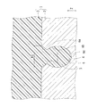
- FIG. 1 is an enlarged cross-sectional view schematically showing a joint portion in the joint structure 1 according to the present embodiment.
- the joint structure 1 is obtained by joining a metal member 2 and a resin member 3.
- a perforated portion 4 that opens on the surface of the metal member 2 is formed.
- the resin member 3 filled in the perforated part 4 in a molten or softened state is solidified in the perforated part 4, whereby the metal member 2 and the resin member 3 are joined. Yes.
- FIG. 1 only one perforated portion 4 is shown to make the drawing easier to see, but actually, a plurality of perforated portions 4 are formed.
- the metal material constituting the metal member 2 examples include iron metal, stainless steel metal, copper metal, aluminum metal, magnesium metal and alloys thereof. Further, the metal member 2 may be a metal molded body, or may be zinc die casting, aluminum die casting, powder metallurgy, or the like.
- the resin constituting the resin member 3 is preferably a thermoplastic resin or a thermosetting resin.
- thermoplastic resins include PVC (polyvinyl chloride), PS (polystyrene), AS (acrylonitrile styrene), ABS (acrylonitrile butadiene styrene), PMMA (polymethyl methacrylate), PE (polyethylene), PP ( Polypropylene), PC (polycarbonate), m-PPE (modified polyphenylene ether), PA6 (polyamide 6), PA66 (polyamide 66), POM (polyacetal), PET (polyethylene terephthalate), PBT (polybutylene terephthalate), PSF (polysulfone) ), PAR (polyarylate), PEI (polyetherimide), PPS (polyphenylene sulfide), PES (polyethersulfone), PEEK (polyetheretherketone), PAI ( Riamidoimido
- the resin member 3 may be TPE (thermoplastic elastomer), and examples of TPE include TPO (olefin-based), TPS (styrene-based), TPEE (ester-based), TPU (urethane-based), and TPA. (Nylon type) and TPVC (vinyl chloride type).
- thermosetting resins examples include EP (epoxy), PUR (polyurethane), UF (urea formaldehyde), MF (melamine formaldehyde), PF (phenol formaldehyde), UP (unsaturated polyester) and SI (silicone). Is mentioned.
- the resin member 3 may be FRP (fiber reinforced plastic).
- a filler may be added to the thermoplastic resin and the thermosetting resin.
- the filler include inorganic fillers (glass fibers, inorganic salts, etc.), metal fillers, organic fillers, and carbon fibers.
- the perforated part 4 is a non-through hole having a substantially circular cross section that opens on the surface of the metal member 2, and a plurality of perforated parts 4 are formed on the surface part of the metal member 2.
- the perforated portion 4 is formed by irradiating the surface portion of the metal member 2 with laser light (laser pulse group) using a laser processing apparatus 50 (see FIG. 5) described later.
- the opening diameter R1 of the perforated part 4 is preferably 30 ⁇ m or more and 100 ⁇ m or less. This is because if the opening diameter R1 is less than 30 ⁇ m, the filling property of the resin member 3 melted or softened at the time of joining into the perforated portion 4 may deteriorate and the joining strength may decrease. On the other hand, if the opening diameter R1 exceeds 100 ⁇ m, the number of perforated portions 4 per unit area may be reduced, and a desired bonding strength may not be obtained.
- the interval between the perforated portions 4 (the distance between the center of a certain perforated portion 4 and the center of the perforated portion 4 adjacent to the certain perforated portion 4) is preferably 200 ⁇ m or less. This is because if the interval between the perforated portions 4 exceeds 200 ⁇ m, the number of perforated portions 4 per unit area may decrease and a desired bonding strength may not be obtained.
- the processing depth of the perforated part 4 is preferably more than 30.0 ⁇ m. This is because if the processing depth of the perforated part 4 is 30.0 ⁇ m or less, the anchor effect obtained by the resin member 3 biting into the perforated part 4 decreases, and the desired joint strength may not be obtained. In addition to this, it is substantially difficult to form the protrusion 5 described later.
- the perforated part 4 has a hole wall 6 narrowed inward in the vicinity of the opening.
- the perforated part 4 extends over the entire circumference of the hole wall 6 of the perforated part 4 having a substantially circular cross section.
- a protruding portion 5 protruding inward from the hole wall 6 is formed.
- the hole wall 6 of the perforated part 4 has a first wall part 6a that inclines inward in the depth direction (Z direction) from the surface side to the back side, and a back side of the first wall part 6a.
- the second wall portion 6b that increases in diameter as it goes from the end portion toward the back side and the third wall portion 6c that decreases in diameter as it goes from the end portion on the back side of the second wall portion 6b to the back side are formed to be continuous.
- a portion where the first wall portion 6a and the second wall portion 6b are connected constitutes the protruding portion 5.
- the dashed-dotted line in FIG. 1 is a virtual line which shows the division
- the protruding portion 5 in the perforated portion 4, the protruding portion of the resin member 3 filled in the perforated portion 4 even when a force that peels the resin member 3 from the metal member 2 is applied. Since the protruding portion 5 is pulled out and becomes a resistance with respect to a portion on the back side from 5, the bonding strength in the peeling direction can be improved. Thereby, in addition to the improvement of the joining strength in the shear direction by filling the perforated part 4 with the resin member 3, the joining strength can be improved also in the peeling direction.
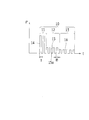
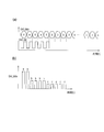
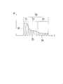
- FIG. 2 is a diagram schematically showing a temporal configuration of the laser pulse group 10.
- the vertical axis P represents the output
- the horizontal axis t represents the time axis.
- Each of the perforated portions 4 irradiates the surface portion of the metal member 2 once with a laser pulse group 10 composed of sub-pulses 14, 15 and 16 each having a period T as shown in FIG. One shot). Therefore, as shown in FIG. 9A, it is possible to form a plurality of perforations 4 on the surface of the metal member 2 by repeatedly irradiating the laser pulse group 10 with a constant period.
- one pulse one laser pulse group 10
- irradiates a laser composed of a plurality of sub-pulses 14, 15 16 easily concentrates laser energy in the depth direction (Z-axis direction). It is suitable for forming the perforated part 4.
- a fiber laser, a YAG laser, a YVO 4 laser, a semiconductor laser, a carbon dioxide laser, an excimer laser, or the like can be selected.
- a semiconductor laser a carbon dioxide laser, an excimer laser, or the like.
- the wavelength of the laser, the fiber laser, the YAG laser, and the YVO 4 laser Each fundamental wave, second, third and fourth harmonics, a semiconductor laser and the like are preferable.
- one cycle T of the subpulses 14, 15, 16 is 15 ns or less. This is because if one cycle T of the subpulses 14, 15, 16 exceeds 15 ns, energy is easily diffused by heat conduction, and it becomes difficult to form the perforated part 4 having the protruding part 5.
- one period T of the subpulses 14, 15 and 16 includes the irradiation time for one time of the subpulses 14, 15, 16 and the next subpulses 14, 15, 16 after the irradiation of the subpulses 14, 15, 16 is completed. The total time with the interval until the start of irradiation.
- the number of subpulses in the laser pulse group 10 is preferably 2 or more and 50 or less. This is because when the number of subpulses exceeds 50, the output per unit of the subpulses 14, 15, and 16 becomes small and it becomes difficult to form the perforated part 4.
- each laser pulse group 10 is configured by combining three subpulse trains 11, 12, and 13 each including subpulses 14, 15, and 16 in the time axis direction.
- the three sub-pulse trains 11, 12, and 13 constituting one laser pulse group 10 are different from each other in peak output and number of sub-pulses 14, 15, and 16 constituting each sub-pulse train 11, 12, and 13. Is set to
- the laser pulse group 10 is a combination of the first sub-pulse train 11, the second sub-pulse train 12, and the third sub-pulse train 13 in this order in the time axis direction.
- the first sub-pulse train 11 is composed of two sub-pulses 14 having a relatively high peak output.
- “relatively high peak output” means a peak output capable of realizing laser energy that is equal to or higher than the processing threshold of the metal member 2 by two subpulses 14.
- the second sub-pulse train 12 is composed of four sub-pulses 15 having a lower peak output (intermediate) than the sub-pulses 14 constituting the first sub-pulse train 11.
- the third sub-pulse train 13 is composed of five sub-pulses 16 having a peak output lower than that of the sub-pulse 15 constituting the second sub-pulse train 12. Note that the pulse width B of each of the subpulses 14, 15, 16 (the irradiation time for one subpulse 14, 15, 16) is set to the same value.
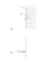
- FIG. 3 is a diagram schematically illustrating a machining state by a sub-pulse train composed of sub-pulses with high peak output.
- the reaction melting or the like
- the reaction does not occur unless the energy of the irradiated laser light is higher than the processing threshold specific to each metal member 2, and in particular, perforation in the metal member 2 having a high surface reflectance and melting point.
- a high peak power is required to start the metal melting.
- FIG. 3 (a) if a sub-pulse having a high peak output is used, even a metal member 2 having a high surface reflectance and a high melting point is 1 as shown in FIG. 3 (b).
- the processing threshold on the surface of the metal member 2 can be exceeded with one or a few (two in FIG. 3A) subpulses.
- the first sub-pulse train 11 composed of the sub-pulses 14 having a relatively high peak output is arranged first, the surface reflectance and the melting point are high. Also for the metal member 2, the surface portion of the metal member 2 can be melted against the surface reflection loss. Further, the laser energy (time integration value of subpulses) of one laser pulse group 10 is limited by the performance of the laser light source 51 (see FIG. 5), but the peak output is high, but a small number (two) of subpulses 14 are used. Since the first sub-pulse train 11 is configured, the laser energy of the entire first sub-pulse train 11 can be kept low within a range that is equal to or greater than the processing threshold of the metal member 2. Therefore, the remaining laser energy can be efficiently used in the second sub-pulse train 12 and the third sub-pulse train 13.
- FIG. 4 is a diagram schematically illustrating a machining state by a subpulse train composed of a number of subpulses having an intermediate peak output.
- the “intermediate peak output” means a peak output lower than the peak output that exceeds the processing threshold.
- the peak output of the subpulse 14 constituting the first subpulse train 11 is set as a high peak output
- the peak output of the sub-pulse 16 constituting the third sub-pulse train 13 is a low peak output, it means the peak output between these.
- the sub-pulse train as shown in FIG. 4A has high energy as a whole because the number of sub-pulses is large. Therefore, when the metal member 2 is irradiated with a sub-pulse train composed of a large number of sub-pulses having an intermediate peak output, a gentle ablation occurs on the surface of the metal member 2 as shown in FIG. As the hole volume of the processed hole 8 increases, the drilling proceeds in the depth direction.
- the second subpulse train 12 constituted by four subpulses 15 having an intermediate peak output is arranged next to the first subpulse train 11. Therefore, since the processed hole 8 after melting formed in the wedge shape by the first sub-pulse train 11, in other words, the processed hole 8 having an increased laser absorption rate is irradiated with high energy laser light. It becomes possible to form the perforated part 4 having a large volume and a deep depth.
- the thermal diffusion effect due to continuous laser irradiation (FIG. 4B).
- the metal on the inner surface of the processed hole 8 is formed by the repeated reflection of the laser light in the processed hole 8 (the perforated portion 4 in the middle of formation) (see the black arrow in FIG. 4B). Melt and evaporate. Thereby, while the volume of the drilling part 4 in the middle of formation increases, drilling advances in the depth direction.
- the metal evaporant 7 from the inner surface of the processed hole 8 scatters as shown by the broken line arrow in FIG.
- the protruding portion 5 that protrudes inward is formed in the hole wall 6 of the portion 4.
- the third sub-pulse train 13 composed of the five sub-pulses 16 having relatively low peak outputs causes further gentle ablation on the surface portion of the metal member 2, and the shape and depth of the perforated portion 4 are reduced. It will be arranged.
- the peak outputs of the subpulses 14, 15, and 16 may increase or decrease unintentionally in the process of amplifying pulsed light (seed light) by optical amplification fibers 61 and 71, which will be described later, for example.
- the present invention controls the peak output and the pulse width B “actively” with the intention of optimizing the shape of the perforated portion 4. Then, when a subpulse with an unintended high peak output and a subpulse with a low peak output are generated, it is possible to feed back this and control the waveform of the laser pulse group 10 "actively".
- the second sub-pulse train 12 is configured by four sub-pulses 15 having the same peak output.
- the shape of the protrusion 5 should be controlled more precisely.
- the peak output of the subpulse 15 may be changed in multiple stages.
- the thermal diffusion length of stainless steel is 0.52 ⁇ m and the thermal diffusion length of copper is 2.6 ⁇ m.
- the region where the laser light intensity is high and the perforation is concentrated is about 10 ⁇ m. Therefore, if the peak output (heat input amount) of the sub-pulse 15 is changed on the order, the reaching of the melting point and boiling point of the metal member 2 in the region where the puncturing is performed intensively will affect the scattering distance. A different metal transpiration 7 will result. Therefore, by controlling the peak output of the subpulse 15 constituting the second subpulse train 12 in consideration of the scattering distance, the shape of the protruding portion 5 can be controlled more precisely.
- a laser processing apparatus 50 using a fiber laser as the laser light source 51 will be described below.
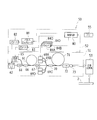
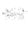
- FIG. 5 is a configuration diagram of the laser processing apparatus 50 including the laser light source 51.
- the laser processing device 50 irradiates a laser light source 51, a control device 52 for controlling the laser light source 51, and laser light emitted from the laser light source 51 toward the metal member 2 to be processed, and A scanning optical system 53 for scanning the laser beam on the surface of the metal member 2.
- LD represents a semiconductor laser.
- the laser light source 51 of this embodiment is a fiber laser whose oscillation method is a MOPA (Master Oscillator Power Amplifier) method.
- the MOPA method is a method in which seed light from a seed light source is amplified by an amplifier.
- a semiconductor laser (LD) capable of high-speed modulation is used as a seed light source, and an optical amplification fiber is used as an amplifier.
- the MOPA method makes it possible to obtain a sufficient peak output even at a high repetition rate. In addition, an optimum output can be obtained regardless of the repetition frequency.
- the laser light source 51 includes an optical amplification fiber 61, a seed LD 62, an isolator 64, an excitation LD 65, a coupler 66, an isolator 67, excitation LDs 69A, 69B, 69C, and 69D, and a coupler 70. And an optical amplifying fiber 71, an isolator 72, and an end cap 73.
- Each of the optical amplification fibers 61 and 71 has a core (not shown) to which a rare earth element as an optical amplification component is added, and a clad (not shown) provided around the core.
- the kind of rare earth element added to the core is not particularly limited, and examples thereof include Er (erbium), Yb (ytterbium), Nd (neodymium), and the like.
- the rare earth element contained in the cores of the optical amplification fibers 61 and 71 absorbs the excitation light, thereby exciting the rare earth element.
- stimulated emission is caused by the excited rare earth element.
- This stimulated emission acts as optical amplification of the seed light, so that the seed light is amplified.
- Each of the optical amplifying fibers 61 and 71 may be a double clad fiber in which two layers of clads are arranged around the core, or a single clad fiber having only one clad. In the case of a single clad fiber, amplification of pulsed light is realized by allowing both pulsed light and pumping light to enter the core.
- the seed LD 62 is a light source that emits seed light.
- the seed LD 62 performs pulse oscillation under the control of the control device 52 and emits pulsed light as seed light.
- the wavelength of the seed light is, for example, a wavelength selected from a range of 1000 nm to 1100 nm.
- the seed light emitted from the seed LD 62 passes through the isolator 64.
- the isolator 64 transmits the seed light from the seed LD 62 and blocks the return light from the optical amplification fiber 61. Thereby, it is possible to prevent the return light from the optical amplifying fiber 61 from entering the seed LD 62.
- the excitation LD 65 is an excitation light source that emits excitation light for exciting the rare earth element added to the core of the optical amplification fiber 61.
- the excitation LD 65 emits excitation light under the control of the control device 52.
- the coupler 66 couples the seed light and the excitation light so that the seed light from the seed LD 62 and the excitation light from the excitation LD 65 enter the optical amplification fiber 61.
- the seed light and the excitation light are incident on the optical amplification fiber 61, the seed light, that is, the pulsed light incident on the optical amplification fiber 61 is amplified.
- the isolator 67 allows the pulse light amplified by the optical amplifying fiber 61 and emitted from the optical amplifying fiber 61 to pass, and blocks light returning to the optical amplifying fiber 61.
- Each of the excitation LDs 69 ⁇ / b> A, 69 ⁇ / b> B, 69 ⁇ / b> C, 69 ⁇ / b> D emits excitation light for exciting rare earth elements contained in the core of the optical amplification fiber 71 under the control of the control device 52.
- four pumping LDs 69A, 69B, 69C, and 69D are provided corresponding to the optical amplification fiber 71, but the number of pumping LDs is not particularly limited.
- the coupler 70 combines the pulsed light and the pumping light so that the pulsed light that has passed through the isolator 67 and the pumped light from the pumping LDs 69A, 69B, 69C, and 69D enter the optical amplification fiber 71. Is. When the pulsed light and the pumping light are incident on the optical amplification fiber 71, the optical amplification fiber 71 amplifies the pulsed light.
- the isolator 72 allows the pulse light emitted from the optical amplification fiber 71 to pass therethrough and blocks light returning to the optical amplification fiber 71.
- the end cap 73 is provided to prevent damage that occurs at the interface between the end face of the optical fiber and the atmosphere when pulsed light with a high peak output is emitted from the optical fiber into the atmosphere.
- control device 52 includes a control unit 80, a pulse generator 81, and drivers 82, 83, 84A, 84B, 84C, and 84D.
- the control unit 80 controls the operation of the laser light source 51 by comprehensively controlling the pulse generator 81 and the drivers 82, 83, 84A, 84B, 84C, and 84D.
- the control unit 80 receives various types of information regarding the processing of the metal member 2 via the personal computer (PC) 55, and based on the information, the pulse generator 81 and the drivers 82, 83, 84A, 84B, 84C, 84D. To control.
- One of the functions of the control unit 80 is to control the operation timing of each of the pulse generator 81 and the drivers 82, 83, 84A, 84B, 84C, and 84D.
- the pulse generator 81 generates a pulse signal and transmits the pulse signal to the driver 82.
- the driver 82 modulates the drive current supplied to the seed LD 62 according to the pulse signal from the pulse generator 81.
- the intensity waveform of the seed light emitted from the seed LD 62 reflects the waveform of the pulse signal generated by the pulse generator 81.
- the driver 83 supplies a drive current to the excitation LD 65 in response to a command from the control unit 80. As a result, the excitation LD 65 emits excitation light.
- Drivers 84A, 84B, 84C, and 84D are provided corresponding to each of the excitation LDs 69A, 69B, 69C, and 69D. Each driver supplies a drive current to the corresponding excitation LD in response to a command from the control unit 80. As a result, each of the excitation LDs 69A, 69B, 69C, and 69D emits excitation light.
- the controller 52 includes a temperature controller for keeping the temperature of these elements constant.
- the scanning optical system 53 is for scanning light from the laser light source 51 on the surface of the metal member 2.
- the scanning direction may be either a one-dimensional direction or a two-dimensional direction.
- the scanning optical system 53 includes, for example, a collimator lens for adjusting the diameter of the laser beam emitted from the laser light source 51 to a predetermined size, and the laser beam after passing through the collimator lens.
- a scanning device for example, a galvano scanner
- a lens for example, an f ⁇ lens
- a metal member 2 that is a workpiece may be moved using a stage (not shown) that can move in a two-dimensional direction.
- various parameters such as the repetition frequency, peak output, and pulse width of the pulsed light emitted from the seed LD 62 are independent of each other. Can be changed. Since the pulsed light is amplified by the optical amplification fibers 61 and 71, the repetition frequency of the laser pulse group 10 emitted from the laser light source 51 and the peak output of the subpulses 14, 15 and 16 constituting the subpulse trains 11, 12 and 13. Various parameters such as the pulse width B and the number can be changed independently of each other.
- the wavelength of the laser light emitted from the fiber laser is substantially the same as the wavelength of the seed light, for example, a wavelength selected from a range of 1000 nm to 1100 nm.
- the pulse width of the seed light can be increased.
- the seed LD 62 is controlled by the pulse generator 81 and the driver 82. Specifically, the driver 82 modulates the drive current applied to the seed LD 62 based on the signal from the pulse generator 81. Thereby, the laser pulse group 10 shown in FIG. 2 is realized.
- a configuration example of the pulse generator 81 and the driver 82 capable of realizing such control will be described below.
- FIG. 6 is a diagram illustrating an example of the configuration of the pulse generator 81 and the driver 82.
- the pulse generator 81 includes a storage unit 91, an FPGA (Field Programmable Gate Array) 92, and a D / A converter 93.
- the driver 82 includes an amplifier 94, a transistor 95, and a resistor 96.
- the storage unit 91 stores waveform data in a nonvolatile manner.
- the FPGA 92 is a digital signal generator and outputs the waveform data read from the storage unit 91 as digital data.
- the FPGA 92 reads the waveform data from the storage unit 91 and outputs the clock signal DAC_clk and the data signal DAC_data (digital data) based on the waveform data.
- the FPGA 92 stops its operation in response to a stop signal from the control unit 80.
- the D / A converter 93 receives the clock signal DAC_clk and the data signal DAC_data, and converts the digital data indicated by the data signal DAC_data into analog data.
- the D / A converter 93 is preferably a D / A converter (high-speed D / A converter) suitable for high-speed signal processing.
- the amplifier 94 converts the current Idac, which is an analog signal from the D / A converter 93, into a signal necessary for controlling the transistor 95.
- a voltage V LD corresponding to the signal output from the amplifier 94 is applied to the control electrode of the transistor 95.
- the drive current I LD flows through the seed LD 62.
- the seed LD 62 oscillates and seed light is emitted from the seed LD 62. Since the current flowing through the transistor 95 is controlled by the voltage V LD , the strength of the drive current I LD is controlled. Thereby, the intensity of the seed light is controlled.
- the storage unit 91 preferably stores a plurality of waveform data. Furthermore, it is preferable that the FPGA 92 can select data according to the application from among a plurality of waveform data included in the storage unit 91.
- a digital signal generator is realized by the FPGA 92. However, for the digital signal generator, a microprocessor, an ASIC (Application Specific Integrated Circuit), or the like may be used.
- FIG. 7 is a diagram for explaining the operation of the pulse generator 81 and the driver 82 having the configuration shown in FIG.
- the D / A converter 93 reads the digital data indicated by the data signal DAC_data in accordance with the rise and fall of the clock signal DAC_clk, and converts the read digital data into analog data.
- An input value of 0 is inserted between a certain value (for example, a) of the input values a, b, and c and the next value (for example, b).
- the input values a, b, c to the D / A converter 93 become smaller from a to c.
- the D / A converter 93, the amplifier 94, and the transistor 95 operate based on this input value, and the drive current I LD is supplied to the seed LD 62, whereby the laser pulse group 10 shown in FIG. 2 can be realized.
- the laser processing unit 50 is used to irradiate the surface of the metal member 2 with the laser pulse group 10 shown in FIG. 2 and, as shown in FIG. In the same manner as shown in FIG. 4B, the perforated portion 4 is formed while forming the protruding portion 5 (perforating step).
- the surface of the metal member 2 is irradiated with a laser beam in a state where the metal member 2 and the resin member 3 are overlapped to melt or soften the resin member 3 (laser irradiation), or the metal member 2 is molded into a mold (
- the perforated portion 4 is filled with the resin member 3 by injecting (injection molding) the molten resin member 3 set in a not-shown state.
- the metal member 2 and the resin member 3 may be joined by hot pressing.
- the resin member 3 filled in the perforated part 4 is solidified in the perforated part 4, whereby the metal member 2 and the resin member 3 are joined to form a joined structure 1 as shown in FIG. Is done.
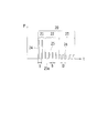
- FIG. 8 is a diagram schematically showing a temporal structure of the laser pulse group 20 according to this modification.
- the pulse widths B of the sub-pulses 14, 15, and 16 are set to the same value.
- the pulse widths of the sub-pulses 24 and 25 constituting the first sub-pulse train 21 and the second sub-pulse train 22 are used.
- b is set to be narrower than the pulse width B of the sub-pulse 26 constituting the third sub-pulse train 23.
- the laser pulse group 20 is a combination of the first sub-pulse train 21, the second sub-pulse train 22, and the third sub-pulse train 23 in this order in the time axis direction.
- the first sub-pulse train 21 is composed of two sub-pulses 24 having a relatively high peak output and a relatively narrow pulse width b.
- the second subpulse train 22 includes four subpulses 25 having a peak output lower than that of the subpulse 24 and having the same pulse width b as that of the subpulse 24.
- the third sub-pulse train 23 is composed of five sub-pulses 26 having a peak output lower than that of the sub-pulse 25 and a wider pulse width B than the pulse width b of the sub-pulses 24 and 25. Note that one period T of the subpulses 24, 25, and 26 is the same as one period T of the subpulses 14, 15, and 16.
- the subpulse 14 is not changed for the first subpulse train 21 without changing the laser energy of the entire first subpulse train 21 (time integration value of the subpulse 24).
- a sub-pulse 24 having a higher peak power can be realized. Thereby, even for the metal member 2 having a higher surface reflectance and melting point, metal melting can be started without increasing the laser energy.
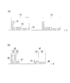
- FIG. 9 is a diagram schematically showing repetitive waveforms of the laser pulse groups 10, 40, and 43.
- FIG. 9A relates to the embodiment
- FIG. 9B relates to the second modification. It is.
- the same laser pulse group 10 is repeated at a constant period, and one perforation 4 is formed by a single shot. The perforated part 4 was formed.
- FIG. 9B two different laser pulse groups 40 and 43 are repeated at a constant period, and one perforated portion 4 is divided into two different laser pulse groups 40 and 43. Try to form.
- the first laser pulse group 40 is divided into a first sub-pulse train 41 composed of sub-pulses 46 having a relatively high peak output, and a second sub-pulse train composed of sub-pulses 47 having an intermediate peak output. 42 in this order in the time axis direction.
- the second laser pulse group 43 is divided into a first sub-pulse train 44 composed of sub-pulses 47 and a second sub-pulse train 45 composed of sub-pulses 48 having a relatively low peak output in the time axis direction. It is composed by combining in order.
- the second laser pulse group 43 is continuously irradiated at the same position to form one perforated portion 4.
- a plurality of perforations 4 are formed by repeating a plurality of times while changing the position on the surface of the metal member 2.
- the shape of the perforated part 4 is controlled by using the limited laser energy to the maximum. Is possible.
- the perforated portion 4 may be formed by repeatedly irradiating only the second laser pulse group 43 at a predetermined period to a plurality of positions irradiated with the first laser pulse group 40.
- the number of subpulses 14 is two, the number of subpulses 15 is four, and the number of subpulses 16 is five.
- the present invention is not limited to this example.
- the number of subpulses 14, 15, 16 may be appropriately determined according to the shape of the part 4.
- each of the sub-pulse trains 11, 12, 13 is composed of a plurality of sub-pulses 14, 15, 16 having the same peak output and pulse width B. Or you may make it comprise with several subpulses from which pulse width B differs.
- a first sub-pulse train 31 composed of two sub-pulses 34 with different peak outputs and a second sub-pulse train 32 composed of four sub-pulses 35 with different peak outputs.
- a third sub-pulse train 33 composed of five sub-pulses 36 having different peak outputs, so as to set a laser pulse group 30 in which the peak output changes not continuously but continuously. May be.
- the present invention it is possible to control the shape of the perforated part formed by the laser beam by efficiently using the limited laser energy. Therefore, the present invention is extremely applicable when applied to the manufacturing method of the bonded structure and the bonded structure. It is beneficial.
Landscapes
- Physics & Mathematics (AREA)
- Engineering & Computer Science (AREA)
- Optics & Photonics (AREA)
- Mechanical Engineering (AREA)
- Plasma & Fusion (AREA)
- Health & Medical Sciences (AREA)
- Electromagnetism (AREA)
- Toxicology (AREA)
- Thermal Sciences (AREA)
- Laser Beam Processing (AREA)
- Lining Or Joining Of Plastics Or The Like (AREA)
Abstract
レーザパルス群を一定周期で繰り返し発振可能なレーザ光源を用意し、樹脂部材(3)との接合面を構成する金属部材(2)の表面部に、レーザ光源を用いて複数の穿孔部(4)を形成する穿孔工程と、複数の穿孔部(4)に樹脂部材(3)を充填することにより、金属部材(2)と樹脂部材(3)とを接合する接合工程と、を含み、レーザパルス群は、サブパルスのピーク出力が互いに異なる複数のサブパルス列を、時間軸方向に組合せることで構成することで、制限されたレーザエネルギを効率的に用いて、レーザ光によって形成される穿孔部(4)の形状を制御する。
Description
本発明は、接合構造体の製造方法および接合構造体に関するものである。
従来から、金属部材と樹脂部材とを接合させた接合構造体が知られている。このような接合構造体では、樹脂部材との接合面を構成する金属部材の表面部に、レーザ光を照射することで穿孔部を形成し、両者を接合する際に溶融または軟化した樹脂部材が穿孔部に充填されることで生じる所謂アンカー効果によって、接合強度を高めることが多い。それ故、接合強度をより一層高めるには、レーザ加工時に穿孔部の形状を制御して、アンカー効果を高めるような形状に形成することが有効となる。
ここで、接合構造体における穿孔部の形成を目的としたものではないが、例えば特許文献1には、ピアシング穴径を小さくし、スパッタ量を低減させることで、ピアシング時間を短縮するレーザ加工方法が開示されている。具体的には、この特許文献1のものは、第1のピアシング条件にてビームを照射する第1の工程と、第2のピアシング条件にてビームを照射する第3の工程との間に、ビーム照射およびアシストガス噴射を一旦停止させる第2の工程を設けることで、酸化燃焼反応を遮断して、過剰の酸化燃焼反応による穴径拡大を防止するようにしている。
しかしながら、金属部材の表面部に穿孔部を形成する際に、上記特許文献1のもののようにビーム照射を一旦停止しただけでは、穿孔部の孔径拡大を抑えることができたとしても、穿孔部の形状を制御することは困難である。
そこで、複数のサブパルスから構成されるレーザパルスを照射する方式が、レーザエネルギを深さ方向に集中させ易いことに着目し、例えば、1パルスが同じピーク出力且つ同じパルス幅を有する複数本のサブパルスで構成されるレーザパルス(以下、レーザパルス群ともいう)を金属部材の表面に照射し、1つのレーザパルス群に含まれるサブパルスの本数を調整することで、穿孔部の形状を制御することが考えられる。
もっとも、金属材料の中には表面反射率が高いものや融点の高いものがあるところ、このような表面反射率や融点の高い金属材料における穿孔開始時には、金属溶融を開始させる(加工閾値を超える)ための高いピーク出力が必要となる。そして、1つのレーザパルス群のレーザエネルギ(サブパルスの時間積分値)にはレーザ光源の性能による制限があるため、ピーク出力の高いサブパルのみでレーザパルス群を構成すると、レーザパルス群に含まれるサブパルスの本数が減少し、穿孔部の形状を制御することが困難になるおそれがある。
一方、穿孔部の形状の制御を優先してサブパルスの本数を増やすと、レーザエネルギの制限により、一本一本のサブパルスのピーク出力が低下するため、表面反射率や融点の高い金属材料に対しては、金属溶融を開始させることが困難になるおそれがある。
本発明はかかる点に鑑みてなされたものであり、その目的とするところは、接合構造体の製造方法および接合構造体において、制限されたレーザエネルギを効率的に用いて、レーザ光によって形成される穿孔部の形状を制御する技術を提供することにある。
前記目的を達成するため、本発明では、金属部材に照射されるレーザパルス群を、互いにパルス波形の異なる複数のサブパルス列を組み合わせることで構成するようにしている。
具体的には、本発明は、金属部材と樹脂部材とが接合された接合構造体の製造方法であって、各々複数のサブパルスで構成されるレーザパルス群を一定周期で繰り返し発振可能なレーザ光源を用意し、前記樹脂部材との接合面を構成する前記金属部材の表面部に、前記レーザ光源を用いて複数の穿孔部を形成する穿孔工程と、前記複数の穿孔部に前記樹脂部材を充填することにより、前記金属部材と当該樹脂部材とを接合する接合工程と、を含み、前記各レーザパルス群は、各々サブパルスで構成され且つサブパルスのピーク出力およびパルス幅の少なくとも一方が互いに異なる複数のサブパルス列を、時間軸方向に組合せることで構成されていることを特徴とするものである。
この構成によれば、互いに異なる複数のサブパルス列を組み合わせて、1つのレーザパルス群を構成することから、例えば、ピーク出力の高いサブパルスで構成されるサブパルス列と、ピーク出力の低いサブパルスで構成されるサブパルス列とを組み合わせたり、パルス幅の狭いサブパルスで構成されるサブパルス列と、パルス幅の広いサブパルスで構成されるサブパルス列とを組み合わせたりすることで、制限されたレーザエネルギを効率的に利用することができる。また、レーザエネルギを効率的に利用することで、複数の穿孔部を形成する際のレーザ加工速度を高めることが可能となる。
そうして、例えば、穿孔開始時にはピーク出力の高いサブパルスで構成されるサブパルス列を配置し、溶融開始後はピーク出力は低いが多数のサブパルスで構成されるサブパルス列を配置するといった具合に、穿孔部の加工段階に応じてサブパルス列を組み合わせてピーク出力やパルス幅やサブパルス本数を能動的に制御することにより、穿孔部の形状を制御することができる。
なお、サブパルスのピーク出力は、例えば、光増幅ファイバによってパルス光(シード光)を増幅する過程で、意図せず高くなったり低くなったりする場合があるが、本発明はこれとは異なり、穿孔部の形状を最適化するという意図のもとに、ピーク出力やパルス幅を「能動的」に制御するものである。
前記接合構造体の製造方法において、前記レーザパルス群は、前記金属部材の加工閾値以上のピーク出力および本数のサブパルスで構成される第1サブパルス列と、当該第1サブパルス列を構成するサブパルスよりもピーク出力が低く且つ本数が多いサブパルスで構成される第2サブパルス列と、を含み、これら第1サブパルス列および第2サブパルス列を時間軸方向にこの順で組み合わせたものであることが好ましい。
この構成によれば、穿孔開始時には、金属部材の加工閾値以上のピーク出力および本数(通常、ピーク出力が高く且つ少数)のサブパルスで構成される第1サブパルス列によって、表面反射ロスに抗しながら金属部材表面の溶融を開始させることができる。また、溶融開始後は、第1サブパルス列を構成するサブパルスよりもピーク出力が低く且つ本数の多いサブパルスで構成される第2サブパルス列によって、形成途中の穿孔部の深部で金属部材を溶融、蒸散させることにより、穿孔を深さ方向に進行させることができる。また、金属部材を溶融、蒸散させることにより生じた金属蒸散物が、穿孔部内で再凝固することにより穿孔部の孔壁に内側に突出する突出部を形成することができる。このようにして形成された突出部は、穿孔部に充填された樹脂部材に対して抜け出し抵抗となることから、剥離方向の接合強度の向上を図ることができる。
前記接合構造体の製造方法において、前記第2サブパルス列を照射した際に、形成途中の前記穿孔部から飛散する金属蒸散物が、当該形成途中の穿孔部の孔壁に付着し再凝固することによって形成される、内側に突出する突出部の形状を制御するように、前記第2サブパルス列を構成するサブパルスのピーク出力を多段階に変化させることが好ましい。
サブパルスのピーク出力を変化させると、金属部材の融点や沸点への到達具合が変化することから、飛散距離の異なる金属蒸散物が生じることになる。それ故、この構成によれば、飛散距離を考慮してサブパルス列を構成するサブパルスのピーク出力を多段階に変化させることで、突出部の形状を最適化することが可能となる。
前記接合構造体の製造方法において、前記穿孔工程では、1つの前記穿孔部を、1つのレーザパルス群を照射することによって形成することが好ましい。
この構成によれば、単一ショット(1回のレーザパルス群の照射)で穿孔部を形成することができるので、接合構造体の製造時間を短縮することができる。
前記接合構造体の製造方法において、前記穿孔工程では、1つの前記穿孔部を、サブパルス列の構成が異なる複数のレーザパルス群を照射することによって形成することが好ましい。
この構成によれば、例えば、1つ目のレーザパルス群を、相対的にピーク出力が高いサブパルス列と中間的なピーク出力のサブパルス列とによって構成するとともに、2つ目のレーザパルス群を、中間的なピーク出力のサブパルス列と相対的にピーク出力が低いサブパルス列とによって構成することで、2回のレーザパルス群の照射で形状が制御された穿孔部を形成するが可能となる。つまり、この構成によれば、1つのレーザパルス群のレーザエネルギでは所望の穿孔部を形成することが困難な場合でも、制限されたレーザエネルギを最大限に利用して穿孔部の形状を制御することが可能となる。
また、本発明は、金属部材と樹脂部材とが接合された接合構造体をも対象としている。
具体的には、本発明は、金属部材と樹脂部材とが接合された接合構造体であって、前記樹脂部材との接合面を構成する前記金属部材の表面部には、各々サブパルスで構成され且つサブパルスのピーク出力およびパルス幅の少なくとも一方が互いに異なる複数のサブパルス列を、時間軸方向に組合せることで構成されたレーザパルス群を照射することにより、孔壁から内側に突出する突出部を有する穿孔部が形成されており、前記複数の穿孔部に前記樹脂部材が充填されていることを特徴とするものである。
この構成によれば、穿孔部の加工段階に応じてサブパルス列を組み合わせて、ピーク出力やパルス幅を能動的に制御することにより、制限されたレーザエネルギを効率的に用いて、突出部を有する穿孔部を形成することができるとともに、かかる穿孔部に溶融または軟化した樹脂部材を充填し固化させることで接合強度を高めることができる。
以上、説明したように本発明に係るに接合構造体の製造方法および接合構造体によれば、制限されたレーザエネルギを効率的に用いて、レーザ光によって形成される穿孔部の形状を制御することができる。
-接合構造体の全体構成-
以下、本発明を実施するための形態を図面に基づいて説明する。
以下、本発明を実施するための形態を図面に基づいて説明する。
図1は、本実施形態に係る接合構造体1における接合部を模式的に示す拡大断面図である。この接合構造体1は、図1に示すように、金属部材2と樹脂部材3とが接合されたものである。接合構造体1における金属部材2と樹脂部材3との接合界面を構成する金属部材2の表面部には、当該金属部材2の表面で開口する穿孔部4が形成されている。そうして、接合構造体1では、溶融または軟化した状態で穿孔部4に充填された樹脂部材3が、穿孔部4内で固化することで、金属部材2と樹脂部材3とが接合されている。なお、図1では、図を見易くするために、穿孔部4を1つだけ示しているが、実際には穿孔部4は複数形成されている。
金属部材2を構成する金属材料の一例としては、鉄系金属、ステンレス系金属、銅系金属、アルミニウム系金属、マグネシウム系金属およびそれらの合金が挙げられる。また、金属部材2は、金属成型体であってもよく、亜鉛ダイカスト、アルミダイカスト、粉末冶金等であってもよい。
一方、樹脂部材3を構成する樹脂は、熱可塑性樹脂または熱硬化性樹脂であることが好ましい。熱可塑性樹脂の一例としては、PVC(ポリ塩化ビニル)、PS(ポリスチレン)、AS(アクリロニトリル・スチレン)、ABS(アクリロニトリル・ブタジエン・スチレン)、PMMA(ポリメチルメタクリレート)、PE(ポリエチレン)、PP(ポリプロピレン)、PC(ポリカーボネート)、m-PPE(変性ポリフェニレンエーテル)、PA6(ポリアミド6)、PA66(ポリアミド66)、POM(ポリアセタール)、PET(ポリエチレンテレフタレート)、PBT(ポリブチレンテレフタレート)、PSF(ポリサルホン)、PAR(ポリアリレート)、PEI(ポリエーテルイミド)、PPS(ポリフェニレンサルファイド)、PES(ポリエーテルサルホン)、PEEK(ポリエーテルエーテルケトン)、PAI(ポリアミドイミド)、LCP(液晶ポリマー)、PVDC(ポリ塩化ビニリデン)、PTFE(ポリテトラフルオロエチレン)、PCTFE(ポリクロロトリフルオロエチレン)およびPVDF(ポリフッ化ビニリデン)が挙げられる。また、樹脂部材3は、TPE(熱可塑性エラストマ)であってもよく、TPEの一例としては、TPO(オレフィン系)、TPS(スチレン系)、TPEE(エステル系)、TPU(ウレタン系)、TPA(ナイロン系)およびTPVC(塩化ビニル系)が挙げられる。
また、熱硬化性樹脂の一例としては、EP(エポキシ)、PUR(ポリウレタン)、UF(ユリアホルムアルデヒド)、MF(メラミンホルムアルデヒド)、PF(フェノールホルムアルデヒド)、UP(不飽和ポリエステル)およびSI(シリコーン)が挙げられる。また、樹脂部材3は、FRP(繊維強化プラスチック)であってもよい。
なお、熱可塑性樹脂および熱硬化性樹脂には、充填剤が添加されていてもよい。充填剤の一例としては、無機系充填剤(ガラス繊維、無機塩類等)、金属系充填剤、有機系充填剤および炭素繊維等が挙げられる。
-穿孔部-
穿孔部4は、金属部材2の表面で開口する、横断面略円形の非貫通孔であり、金属部材2の表面部に複数形成されている。この穿孔部4は、金属部材2の表面部に、後述するレーザ加工装置50(図5参照)を用いてレーザ光(レーザパルス群)を照射することによって形成される。
穿孔部4は、金属部材2の表面で開口する、横断面略円形の非貫通孔であり、金属部材2の表面部に複数形成されている。この穿孔部4は、金属部材2の表面部に、後述するレーザ加工装置50(図5参照)を用いてレーザ光(レーザパルス群)を照射することによって形成される。
穿孔部4の開口径R1は、30μm以上、100μm以下が好ましい。これは、開口径R1が30μm未満では、接合時に溶融または軟化した樹脂部材3の穿孔部4への充填性が悪化して接合強度が低下する場合があるからである。一方、開口径R1が100μmを超えると、単位面積あたりの穿孔部4の数が減少して所望の接合強度が得られない場合があるからである。
また、穿孔部4の間隔(或る穿孔部4の中心と、当該或る穿孔部4と隣接する穿孔部4の中心との距離)は、200μm以下であることが好ましい。これは、穿孔部4の間隔が200μmを超えると、単位面積あたりの穿孔部4の数が減少して所望の接合強度が得られない場合があるからである。
さらに、穿孔部4の加工深さは、30.0μmを超えることが好ましい。これは、穿孔部4の加工深さが30.0μm以下であると、樹脂部材3が穿孔部4に食い込むことで得られるアンカー効果が減少し、所望の接合強度が得られない場合があることに加え、後述する突出部5を形成することが実質的に困難となるからである。
この穿孔部4には、図1に示すように、開口部の近傍に孔壁6を内側に絞ったような、換言すると、横断面略円形の穿孔部4の孔壁6の全周に亘って当該孔壁6から内側に突出する突出部5が形成されている。より詳しくは、穿孔部4の孔壁6は、深さ方向(Z方向)において、表面側から奥側に行くほど内側に傾斜する第1壁部6aと、第1壁部6aの奥側の端部から奥側に行くほど拡径する第2壁部6bと、第2壁部6bの奥側の端部から奥側に行くほど縮径する第3壁部6cとが連なるように形成されていて、第1壁部6aと第2壁部6bとが繋がる部分が突出部5を構成している。なお、図1における一点鎖線は、第2壁部6bと第3壁部6cとの区分を示す仮想線である。
このように、突出部5を穿孔部4に形成することにより、樹脂部材3を金属部材2から剥離するような力が作用した場合でも、穿孔部4に充填された樹脂部材3のうち突出部5よりも奥側の部位に対して、突出部5が抜け出し抵抗となることから、剥離方向の接合強度の向上を図ることができる。これにより、穿孔部4に樹脂部材3を充填することによるせん断方向の接合強度の向上に加え、剥離方向についても接合強度の向上を図ることができる。さらに、熱サイクル環境下において、金属部材2および樹脂部材3の線膨張係数差に起因する剥離応力が発生しても、接合強度を維持することができ、これにより、熱サイクル環境下における耐久性の向上を図ることができる。以下、このような突出部5を有する穿孔部4を形成するためのレーザ加工方法について説明する。
-レーザ加工方法-
図2は、レーザパルス群10の時間的構成を模式的に示す図である。なお、図2の縦軸Pは出力を示し、横軸tは時間軸を示している。各穿孔部4は、図2に示すような、各々1周期がTであるサブパルス14,15,16によって構成されるレーザパルス群10を、金属部材2の表面部に1回照射すること(単一ショット)によって形成される。それ故、図9(a)に示すように、レーザパルス群10を一定周期で繰り返し照射することで、金属部材2の表面部に複数の穿孔部4を形成することが可能となっている。このような1パルス(1つのレーザパルス群10)が複数のサブパルス14,15,16から構成されるレーザを照射する方式は、レーザエネルギを深さ方向(Z軸方向)に集中させ易いので、穿孔部4を形成するのに好適である。
図2は、レーザパルス群10の時間的構成を模式的に示す図である。なお、図2の縦軸Pは出力を示し、横軸tは時間軸を示している。各穿孔部4は、図2に示すような、各々1周期がTであるサブパルス14,15,16によって構成されるレーザパルス群10を、金属部材2の表面部に1回照射すること(単一ショット)によって形成される。それ故、図9(a)に示すように、レーザパルス群10を一定周期で繰り返し照射することで、金属部材2の表面部に複数の穿孔部4を形成することが可能となっている。このような1パルス(1つのレーザパルス群10)が複数のサブパルス14,15,16から構成されるレーザを照射する方式は、レーザエネルギを深さ方向(Z軸方向)に集中させ易いので、穿孔部4を形成するのに好適である。
レーザの種類としては、ファイバレーザ、YAGレーザ、YVO4レーザ、半導体レーザ、炭酸ガスレーザ、エキシマレーザ等を選択することができ、レーザの波長を考慮すると、ファイバレーザおよびYAGレーザおよびYVO4レーザの、それぞれの基本波並びに第2、第3および第4高調波、半導体レーザ等が好ましい。
また、サブパルス14,15,16の1周期Tは15ns以下であることが好ましい。これは、サブパルス14,15,16の1周期Tが15nsを超えると、熱伝導によりエネルギが拡散し易くなり、突出部5を有する穿孔部4を形成し難くなるためである。なお、サブパルス14,15,16の1周期Tは、サブパルス14,15,16の1回分の照射時間と、そのサブパルス14,15,16の照射が終了されてから次回のサブパルス14,15,16の照射が開始されるまでの間隔との合計時間である。
また、レーザパルス群10のサブパルス数は、2以上50以下であることが好ましい。これは、サブパルス数が50を超えると、サブパルス14,15,16の単位あたりの出力が小さくなり、穿孔部4を形成し難くなるためである。
各レーザパルス群10は、図2に示すように、各々サブパルス14,15,16で構成される3つのサブパルス列11,12,13を、時間軸方向に組合せることで構成されている。そうして、1つのレーザパルス群10を構成する3つのサブパルス列11,12,13は、各サブパルス列11,12,13を構成するサブパルス14,15,16のピーク出力および本数が互いに異なるように設定されている。
具体的には、レーザパルス群10は、第1サブパルス列11、第2サブパルス列12および第3サブパルス列13を、時間軸方向にこの順で組み合わせたものである。第1サブパルス列11は、相対的にピーク出力が高い2本のサブパルス14によって構成されている。ここで、「相対的にピーク出力が高い」とは、2本のサブパルス14によって金属部材2の加工閾値以上となるようなレーザエネルギを実現できるピーク出力をいう。また、第2サブパルス列12は、第1サブパルス列11を構成するサブパルス14よりもピーク出力が低い(中間的な)4本のサブパルス15によって構成されている。さらに、第3サブパルス列13は、第2サブパルス列12を構成するサブパルス15よりもピーク出力が低い5本のサブパルス16によって構成されている。なお、各サブパルス14,15,16のパルス幅B(サブパルス14,15,16の1回分の照射時間)は同じ値に設定されている。
図3は、ピーク出力の高いサブパルスで構成されるサブパルス列による加工状態を模式的に説明する図である。レーザ加工では、照射されるレーザ光のエネルギが、各金属部材2に固有の加工閾値以上に強くなければ反応(溶融等)は起こらず、特に、表面反射率や融点の高い金属部材2における穿孔開始時には、金属溶融を開始させるための高いピーク出力が必要となる。逆に言えば、図3(a)に示すように、ピーク出力の高いサブパルスを用いれば、表面反射率や融点の高い金属部材2に対しても、図3(b)に示すように、1つまたは少数(図3(a)では2本)のサブパルスで金属部材2の表面における加工閾値を超えることが可能となる。
この点、本実施形態では、図2に示すように、相対的にピーク出力の高いサブパルス14で構成される第1サブパルス列11を最初に配置していることから、表面反射率や融点の高い金属部材2に対しても、表面反射ロスに抗しながら金属部材2の表面部を溶融させることができる。また、1つのレーザパルス群10のレーザエネルギ(サブパルスの時間積分値)にはレーザ光源51(図5参照)の性能による制限があるが、ピーク出力は高いものの少数(2本)のサブパルス14で第1サブパルス列11を構成していることから、金属部材2の加工閾値以上となる範囲で第1サブパルス列11全体のレーザエネルギを低く抑えることができる。したがって、残りのレーザエネルギを第2サブパルス列12や第3サブパルス列13において効率的に用いることが可能となる。
そうして、相対的にピーク出力の高いサブパルス14を金属部材2の表面に照射すると、図3(b)に示すのと同様に、金属部材2の表面部に急激なアブレーション(材料の表面が蒸発によって分解する現象)が生じる。この際、膨張圧により溶融金属(金属蒸散物)7が、図3(b)の破線矢印で示すように、レーザ光照射箇所の周辺部に飛び散ることで、穿孔の取っ掛かりとなる楔形状の加工穴8が形成される。
図4は、中間的なピーク出力を有する多数のサブパルスで構成されるサブパルス列による加工状態を模式的に説明する図である。なお、「中間的なピーク出力」とは、加工閾値を超えるようなピーク出力よりも低いピーク出力を意味し、例えば、第1サブパルス列11を構成するサブパルス14のピーク出力を高いピーク出力とし、第3サブパルス列13を構成するサブパルス16のピーク出力を低いピーク出力とした場合における、これらの間のピーク出力を意味する。
図4(a)に示すようなサブパルス列は、加工閾値を超えるようなピーク出力よりもピーク出力が低いものの、サブパルスの本数が多いことから、全体として高エネルギとなっている。それ故、中間的なピーク出力を有する多数のサブパルスで構成されるサブパルス列を金属部材2に照射すると、図4(b)に示すように、金属部材2の表面部に緩やかなアブレーションが生じて、加工穴8の穴体積が増加するとともに、穿孔が深さ方向に進行することになる。
この点、本実施形態では、図2に示すように、中間的なピーク出力を有する4本のサブパルス15によって構成される第2サブパルス列12を、第1サブパルス列11の次に配置していることから、第1サブパルス列11によって楔形状に形成された溶融後の加工穴8に、換言すると、レーザ吸収率が増加した加工穴8に高エネルギのレーザ光が照射されることになるので、体積が大きく且つ深い穿孔部4を形成することが可能になる。
具体的には、図4(b)に示すのと同様に、中間的なピーク出力の多数のサブパルス15を加工穴8に照射すると、持続的なレーザ照射による熱拡散効果(図4(b)の白抜き矢印参照)と、加工穴8(形成途中の穿孔部4)内でのレーザ光の繰り返し反射(図4(b)の黒塗り矢印参照)とにより、加工穴8内表面の金属が溶融、蒸散する。これにより、形成途中の穿孔部4の体積が増加するとともに、穿孔が深さ方向に進行することになる。
その一方で、加工穴8内表面からの金属蒸散物7が、図4(b)の破線矢印で示すように飛散し、形成途中の穿孔部4の開口部付近で再凝固することにより、穿孔部4の孔壁6に内側に突出する突出部5を形成することになる。
その後、相対的に低いピーク出力を有する5本のサブパルス16によって構成される第3サブパルス列13によって、金属部材2の表面部にさらに緩やかなアブレーションが生じて、穿孔部4の形状および深さが整えられることになる。
なお、サブパルス14,15,16のピーク出力は、例えば、後述する光増幅ファイバ61,71によってパルス光(シード光)を増幅する過程で、意図せず高くなったり低くなったりする場合があるが、本発明はこれとは異なり、穿孔部4の形状を最適化するという意図のもとに、ピーク出力やパルス幅Bを「能動的」に制御するものである。そうして、意図しないピーク出力が高いサブパルスとピーク出力が低いサブパルスとが生じる場合には、これをフィードバックして、レーザパルス群10の波形を「能動的」に制御することも可能である。
また、本実施形態では、同じピーク出力を有する4本のサブパルス15によって第2サブパルス列12を構成したが、より強固な突出部を実現するために突出部5の形状をより精密に制御するべく、サブパルス15のピーク出力を多段階に変化させるようにしてもよい。より詳しくは、形成途中の穿孔部4内では、(1)レーザ光が集中的に照射される箇所での金属表面によるレーザ光の吸収、(2)金属表面の局所的温度上昇、(3)金属表面における金属の溶融、(4)金属の気化、というプロセスにより穿孔が進行し、気化した金属蒸散物7等は、上述の如く、形成途中の穿孔部4内で再凝固して突出部5を形成する。このとき、サブパルス15が繰り返されると、レーザ光が集中的に照射される箇所での金属表面の温度は、入熱により上昇する一方、入熱の一時的な停止(図2の符号15a参照)による熱拡散により低下する。この温度サイクルは金属部材2の融点や沸点への到達具合に影響することになる。
実際、例えばサブパルスの1周期Tが15nsの場合には、ステンレスの熱拡散長は0.52μmであり、銅の熱拡散長は2.6μmである。また、例えば開口径R1が30μmの穿孔部4の場合には、レーザ光強度が高く集中的に穿孔が行われるのは10μm程度の領域である。それ故、オーダ的に、サブパルス15のピーク出力(入熱量)を変化させると、集中的に穿孔が行われる領域における金属部材2の融点や沸点への到達具合に影響が生じるため、飛散距離の異なる金属蒸散物7が生じることになる。したがって、飛散距離を考慮して第2サブパルス列12を構成するサブパルス15のピーク出力を制御することで、突出部5の形状をより精密に制御することが可能となる。
-レーザ加工装置-
上述したレーザパルス群を一定周期で繰り返し発振可能なレーザ加工装置の一例として、以下では、レーザ光源51としてファイバレーザを用いたレーザ加工装置50について説明する。
上述したレーザパルス群を一定周期で繰り返し発振可能なレーザ加工装置の一例として、以下では、レーザ光源51としてファイバレーザを用いたレーザ加工装置50について説明する。
図5は、レーザ光源51を含むレーザ加工装置50の構成図である。このレーザ加工装置50は、レーザ光源51と、レーザ光源51を制御するための制御装置52と、レーザ光源51から発せられたレーザ光を、加工対象である金属部材2に向けて照射し、かつ金属部材2の表面上でレーザ光を走査するための走査光学系53と、を備えている。なお、以下の説明中の「LD」は、半導体レーザを表わしている。
本実施形態のレーザ光源51は、発振方式がMOPA(Master Oscillator Power Amplifier)方式のファイバレーザであ。MOPA方式とは、シード光源からのシード光をアンプにより増幅する方式である。本実施形態では、シード光源として高速での変調が可能な半導体レーザ(LD)を利用するとともに、アンプとして光増幅ファイバを利用する。MOPA方式によって、高繰り返し時にも充分なピーク出力を得ることが可能になる。加えて、その繰り返し周波数に関わらず最適な出力を得ることができる。
具体的には、レーザ光源51は、光増幅ファイバ61と、シードLD62と、アイソレータ64と、励起LD65と、結合器66と、アイソレータ67と、励起LD69A,69B,69C,69Dと、結合器70と、光増幅ファイバ71と、アイソレータ72と、エンドキャップ73と、を有している。
各光増幅ファイバ61,71は、光増幅成分である希土類元素が添加されたコア(図示せず)と、当該コアの周囲に設けられるクラッド(図示せず)と、を有している。コアに添加される希土類元素の種類は、特に限定されず、例えばEr(エルビウム)、Yb(イッテルビウム)、Nd(ネオジム)等が挙げられる。
このレーザ加工装置50では、光増幅ファイバ61,71のコアに含まれる希土類元素が励起光を吸収することによって、当該希土類元素が励起される。この状態においてシード光が光増幅ファイバ61,71のコアを伝播すると、励起された希土類元素による誘導放出が生じる。この誘導放出がシード光の光増幅として作用することでシード光が増幅される。なお、各光増幅ファイバ61,71は、コアの周囲に2層のクラッドが配置されたダブルクラッドファイバでも、クラッドが1層のみであるシングルクラッドファイバでもよい。なおシングルクラッドファイバの場合には、パルス光および励起光がともにコアに入射することによってパルス光の増幅が実現される。
シードLD62は、シード光を発する光源である。シードLD62は、制御装置52の制御によりパルス発振して、パルス光をシード光として発する。なおシード光の波長は、例えば1000nm以上1100nm以下の範囲から選択された波長である。
シードLD62から出射されたシード光は、アイソレータ64を通過する。アイソレータ64は、シードLD62からのシード光を透過させるとともに光増幅ファイバ61からの戻り光を遮断する。これによって光増幅ファイバ61からの戻り光がシードLD62に入射するのを防ぐことができる。
励起LD65は、光増幅ファイバ61のコアに添加された希土類元素を励起するための励起光を発する励起光源である。励起LD65は、制御装置52の制御により励起光を発する。
結合器66は、シードLD62からのシード光および励起LD65からの励起光を光増幅ファイバ61に入射させるために、シード光および励起光を結合する。シード光と励起光とが光増幅ファイバ61に入射されることにより、シード光すなわち光増幅ファイバ61に入射したパルス光が増幅される。
アイソレータ67は、光増幅ファイバ61によって増幅されて光増幅ファイバ61から出射されたパルス光を通過させるとともに、光増幅ファイバ61に戻る光を遮断する。
励起LD69A,69B,69C,69Dの各々は、制御装置52の制御により、光増幅ファイバ71のコアに含まれる希土類元素を励起するための励起光を発する。なお、図5では光増幅ファイバ71に対応して4個の励起LD69A,69B,69C,69Dが設けられているが、励起LDの個数は特に限定されるものではない。
結合器70は、アイソレータ67を通過したパルス光と、励起LD69A,69B,69C,69Dからの励起光とを光増幅ファイバ71に入射させるために、当該パルス光と励起光とを結合するためのものである。パルス光と励起光とが光増幅ファイバ71に入射されることにより、光増幅ファイバ71は、当該パルス光を増幅する。
アイソレータ72は光増幅ファイバ71から出射されたパルス光を通過させるとともに、光増幅ファイバ71に戻る光を遮断する。エンドキャップ73は、ピーク出力の高いパルス光が光ファイバから大気中に出射される際に、光ファイバの端面と大気との境界面で生じるダメージを防止するために設けられている。
一方、制御装置52は、制御部80と、パルスジェネレータ81と、ドライバ82,83,84A,84B,84C,84Dとを有している。
制御部80は、パルスジェネレータ81およびドライバ82,83,84A,84B,84C,84Dを統括的に制御することにより、レーザ光源51の動作を制御する。制御部80は、パーソナルコンピュータ(PC)55を介して、金属部材2の加工に関する各種の情報を受けるとともに、その情報に基づいて、パルスジェネレータ81およびドライバ82,83,84A,84B,84C,84Dを制御する。制御部80の機能の一つとしては、パルスジェネレータ81およびドライバ82,83,84A,84B,84C,84Dの各々の動作タイミングの制御が挙げられる。
パルスジェネレータ81は、パルス信号を発生させるとともに、そのパルス信号をドライバ82に送信する。ドライバ82は、パルスジェネレータ81からのパルス信号に応じて、シードLD62に供給する駆動電流を変調させる。シードLD62に供給される駆動電流が変調されることにより、シードLD62から発せられるシード光の強度波形は、パルスジェネレータ81により発生したパルス信号の波形を反映したものとなる。
ドライバ83は、制御部80の指令に応答して、励起LD65に駆動電流を供給する。これにより励起LD65は励起光を発する。
ドライバ84A,84B,84C,84Dは、励起LD69A,69B,69C,69Dの各々に対応して設けられる。各ドライバは、制御部80の指令に応答して、対応する励起LDに駆動電流を供給する。これにより励起LD69A,69B,69C,69Dの各々は励起光を発する。
なお、シードLD62、励起LD69A,69B,69C,69D、アイソレータ64,67,72等、ファイバレーザを構成する素子の特性は、温度に応じて変化し得る。したがって、これらの素子の温度を一定に保つための温度コントローラが制御装置52に含まれていることが、より好ましい。
走査光学系53は、金属部材2の表面上でレーザ光源51からの光を走査するためのものである。走査方向は1次元方向および2次元方向のいずれでもよい。図示しないが、走査光学系53は、たとえばレーザ光源51から出射されるレーザ光のビームの径を所定の大きさに調整するためのコリメータレンズ、および、コリメータレンズを通過した後のレーザ光を金属部材2の表面上で二次元方向に走査するための走査装置(例えばガルバノスキャナ)、その走査装置により走査されたレーザ光を集光するためのレンズ(例えばfθレンズ)等により構成される。なお、走査装置に代えて、二次元方向に移動可能なステージ(図示せず)を用いて、ワークである金属部材2を移動させるようにしてもよい。
以上のように構成されたレーザ加工装置50では、シードLD62に供給されるパルス電流を制御することによって、シードLD62から発せられるパルス光の繰り返し周波数、ピーク出力、パルス幅等の各種パラメータを互いに独立に変更できる。そのパルス光が光増幅ファイバ61,71により増幅されるので、レーザ光源51から出射されるレーザパルス群10の繰り返し周波数、サブパルス列11,12,13を構成するサブパルス14,15,16のピーク出力、パルス幅B、本数等の各種パラメータを互いに独立に変更することができることになる。
また、ファイバレーザ(光増幅ファイバ71)から出射されるレーザ光の波長は、実質的に、シード光の波長と同じであり、たとえば1000nm以上1100nm以下の範囲から選択された波長となる。
さらに、パルス幅Bが広いサブパルス14,15,16を照射するには、シード光のパルス幅を長くする必要があるが、この場合には、ドライバ82からシードLD62に供給されるパルス電流のパルス幅を長くすることによって、シード光のパルス幅を長くすることができる。
[シードLDの制御回路の構成例]
本実施形態では、パルスジェネレータ81およびドライバ82によりシードLD62が制御される。具体的には、ドライバ82は、パルスジェネレータ81からの信号に基づいて、シードLD62に与える駆動電流を変調する。これにより、図2に示すレーザパルス群10が実現される。このような制御を実現可能なパルスジェネレータ81およびドライバ82の構成例を以下に説明する。
本実施形態では、パルスジェネレータ81およびドライバ82によりシードLD62が制御される。具体的には、ドライバ82は、パルスジェネレータ81からの信号に基づいて、シードLD62に与える駆動電流を変調する。これにより、図2に示すレーザパルス群10が実現される。このような制御を実現可能なパルスジェネレータ81およびドライバ82の構成例を以下に説明する。
図6は、パルスジェネレータ81およびドライバ82の構成の一例を示す図である。パルスジェネレータ81は、記憶部91と、FPGA(Field Programmable Gate Array)92と、D/Aコンバータ93とを有している。ドライバ82は、アンプ94と、トランジスタ95と、抵抗96とを有している。
記憶部91は、波形データを不揮発的に記憶する。FPGA92はデジタル信号発生器であり、記憶部91から読み出した波形データをデジタルデータとして出力する。FPGA92は、制御部80からの動作信号を受けると、記憶部91から波形データを読み出すとともに、その波形データに基づいてクロック信号DAC_clkと、データ信号DAC_data(デジタルデータ)とを出力する。FPGA92は、制御部80からの停止信号に応じてその動作を停止する。
D/Aコンバータ93は、クロック信号DAC_clkと、データ信号DAC_dataとを受けて、データ信号DAC_dataにより示されるデジタルデータをアナログデータに変換する。D/Aコンバータ93は、高速の信号処理に適したD/Aコンバータ(高速D/Aコンバータ)であることが好ましい。
アンプ94は、D/Aコンバータ93からのアナログ信号である電流Idacをトランジスタ95の制御に必要な信号に変換する。トランジスタ95の制御電極には、アンプ94から出力された信号に対応する電圧VLDが与えられる。
トランジスタ95が電圧VLDに応じて導通するとシードLD62に駆動電流ILDが流れる。駆動電流ILDが閾値電流より大きくなるとシードLD62がレーザ発振してシードLD62からシード光が発せられる。電圧VLDによってトランジスタ95に流れる電流が制御されるので駆動電流ILDの強度が制御される。これによりシード光の強度が制御される。
なお、記憶部91は複数の波形データを保存することが望ましい。さらに、FPGA92は、記憶部91に含まれる複数の波形データの中から、用途に応じたデータを選択できることが好ましい。また、図6に示した構成では、FPGA92によってデジタル信号発生器が実現される。ただし、デジタル信号発生器には、マイクロプロセッサやASIC(Application Specific Integrated Circuit)などを用いてもよい。
図7は、図6に示した構成を有するパルスジェネレータ81およびドライバ82の動作を説明するための図である。図7(a)に示すように、D/Aコンバータ93は、クロック信号DAC_clkの立ち上がりおよび立下りに応じて、データ信号DAC_dataが示すデジタルデータを読み込み、その読み込んだデジタルデータをアナログデータに変換する。入力値a,b,cのある値(たとえばa)とその次の値(たとえばb)との間には、入力値として0が挟まれる。
図7(b)に示すように、D/Aコンバータ93への入力値a,b,cは、aからcの順に小さくなる。この入力値に基づいてD/Aコンバータ93、アンプ94およびトランジスタ95が動作し、駆動電流ILDをシードLD62に供給することで、図2に示すレーザパルス群10を実現することができる。
-接合構造体の製造方法-
次に、上記レーザ加工装置50を用いた本実施形態に係る接合構造体1の製造方法について説明する。
次に、上記レーザ加工装置50を用いた本実施形態に係る接合構造体1の製造方法について説明する。
先ず、レーザ加工装置50を用いて、図2に示すレーザパルス群10を、金属部材2の表面に照射して、図3(b)に示すのと同様に、穿孔の取っ掛かりとなる楔形状の加工穴8するとともに、図4(b)に示すのと同様に、突出部5を形成しながら穿孔部4を形成する(穿孔工程)。
その後、例えば、金属部材2と樹脂部材3とを重ねた状態で金属部材2の表面にレーザ光を照射して樹脂部材3を溶融または軟化させたり(レーザ照射)、金属部材2を金型(図示せず)にセットして溶融した樹脂部材3を射出したり(射出成型)することにより、樹脂部材3を穿孔部4に充填する。なお、金属部材2と樹脂部材3とは熱プレスによって接合してもよい。そうして、穿孔部4に充填された樹脂部材3が、穿孔部4内で固化することによって、金属部材2と樹脂部材3とが接合され、図1に示すような接合構造体1が形成される。
-変形例-
次に、上記実施形態に係る接合構造体1の製造方法の変形例について説明する。
次に、上記実施形態に係る接合構造体1の製造方法の変形例について説明する。
[変形例1]
図8は、本変形例に係るレーザパルス群20の時間的構成を模式的に示す図である。上記実施形態では、各サブパルス14,15,16のパルス幅Bを同じ値に設定したが、本変形例では、第1サブパルス列21および第2サブパルス列22を構成するサブパルス24,25のパルス幅b(サブパルス24,25の1回分の照射時間)を、第3サブパルス列23を構成するサブパルス26のパルス幅Bよりも狭く設定している。
図8は、本変形例に係るレーザパルス群20の時間的構成を模式的に示す図である。上記実施形態では、各サブパルス14,15,16のパルス幅Bを同じ値に設定したが、本変形例では、第1サブパルス列21および第2サブパルス列22を構成するサブパルス24,25のパルス幅b(サブパルス24,25の1回分の照射時間)を、第3サブパルス列23を構成するサブパルス26のパルス幅Bよりも狭く設定している。
具体的には、レーザパルス群20は、図8に示すように、第1サブパルス列21、第2サブパルス列22および第3サブパルス列23を、時間軸方向にこの順で組み合わせたものである。第1サブパルス列21は、相対的にピーク出力が高く且つ相対的にパルス幅bが狭い2本のサブパルス24によって構成されている。第2サブパルス列22は、サブパルス24よりもピーク出力が低く且つサブパルス24と同じパルス幅bの4本のサブパルス25によって構成されている。第3サブパルス列23は、サブパルス25よりもピーク出力が低く且つサブパルス24,25のパルス幅bよりもパルス幅Bの広い5本のサブパルス26によって構成されている。なお、サブパルス24,25,26の1周期Tは、サブパルス14,15,16の1周期Tと同じである。
このように、サブパルス24,25のパルス幅bを狭くすることで、第1サブパルス列21については、第1サブパルス列21全体のレーザエネルギ(サブパルス24の時間積分値)を変えずに、サブパルス14よりも高いピーク出力を有するサブパルス24を実現することができる。これにより、表面反射率や融点のより高い金属部材2に対しても、レーザエネルギを増やすことなく、金属溶融を開始させることができる。
一方、第2サブパルス列22については、ピーク出力およびサブパルス25の本数の制御に加え、入熱が一時的に停止する期間(図8の符号25a参照)を増やす制御を加えることで、金属蒸散物7の状態をさらに細かく制御することが可能になる。
[変形例2]
図9は、レーザパルス群10,40,43の繰り返し波形を模式的に示す図であり、図9(a)は実施形態に係るものであり、図9(b)は変形例2に係るものである。上記実施形態では、図9(a)に示すように、同じレーザパルス群10を一定周期で繰り返し、1つの穿孔部4を単一ショットによって形成することで、金属部材2の表面部に複数の穿孔部4を形成するようにした。これに対し、本変形例では、図9(b)に示すように、異なる2つのレーザパルス群40,43を一定周期で繰り返し、1つの穿孔部4を異なる2つのレーザパルス群40,43によって形成するようにしている。
図9は、レーザパルス群10,40,43の繰り返し波形を模式的に示す図であり、図9(a)は実施形態に係るものであり、図9(b)は変形例2に係るものである。上記実施形態では、図9(a)に示すように、同じレーザパルス群10を一定周期で繰り返し、1つの穿孔部4を単一ショットによって形成することで、金属部材2の表面部に複数の穿孔部4を形成するようにした。これに対し、本変形例では、図9(b)に示すように、異なる2つのレーザパルス群40,43を一定周期で繰り返し、1つの穿孔部4を異なる2つのレーザパルス群40,43によって形成するようにしている。
具体的には、第1のレーザパルス群40を、相対的にピーク出力が高いサブパルス46で構成される第1サブパルス列41と、中間的なピーク出力のサブパルス47で構成される第2サブパルス列42と、を時間軸方向にこの順で組み合わせることで構成している。また、第2のレーザパルス群43を、サブパルス47で構成される第1サブパルス列44と、相対的にピーク出力が低いサブパルス48で構成される第2サブパルス列45と、を時間軸方向にこの順で組み合わせることで構成している。そうして、金属部材2の表面に第1のレーザパルス群40を照射した後、同じ位置に第2のレーザパルス群43を続けて照射することで1つの穿孔部4を形成し、これを金属部材2の表面における位置を変えながら複数回繰り返すことで複数の穿孔部4を形成する。
この変形例によれば、1つのレーザパルス群のレーザエネルギでは穿孔部4を形成することが困難な場合でも、制限されたレーザエネルギを最大限に利用して穿孔部4の形状を制御することが可能となる。
なお、図9(b)に示す繰り返し波形とは異なり、金属部材2の表面における複数の位置(穿孔部4の形成予定位置)に、第1のレーザパルス群40のみを一定周期で繰り返して照射した後、第1のレーザパルス群40が照射された複数の位置に、第2のレーザパルス群43のみを一定周期で繰り返して照射することにより、穿孔部4を形成するようにしてもよい。
(その他の実施形態)
本発明は、実施形態に限定されず、その精神または主要な特徴から逸脱することなく他の色々な形で実施することができる。
本発明は、実施形態に限定されず、その精神または主要な特徴から逸脱することなく他の色々な形で実施することができる。
上記実施形態では、サブパルス14を2本とし、サブパルス15を4本とし、サブパルス16を5本としたが、これは例示であり、これに限らず、例えば金属部材2の材種や形成する穿孔部4の形状等に応じてサブパルス14,15,16の本数を適宜決定してもよい。
上記実施形態では、各サブパルス列11,12,13を、ピーク出力およびパルス幅Bを同じくする複数のサブパルス14,15,16で構成したが、これに限らず、1つのサブパルス列を、ピーク出力またはパルス幅Bが異なる複数のサブパルスで構成するようにしてもよい。具体的には、図10に示すように、ピーク出力の異なる2本のサブパルス34で構成される第1サブパルス列31と、ピーク出力の異なる4本のサブパルス35で構成される第2サブパルス列32と、ピーク出力の異なる5本のサブパルス36で構成される第3サブパルス列33とを組み合わせて、ピーク出力が段階的ではなく、連続的に近い形で変化するレーザパルス群30を設定するようにしてもよい。
このように、上述の実施形態はあらゆる点で単なる例示に過ぎず、限定的に解釈してはならない。さらに、特許請求の範囲の均等範囲に属する変形や変更は、全て本発明の範囲内のものである。この出願は、日本特許出願の特願2015-049390号に基づく優先権を請求する。これに言及することにより、その全ての内容は本出願に組み込まれるものである。
本発明によると、制限されたレーザエネルギを効率的に用いて、レーザ光によって形成される穿孔部の形状を制御することができるので、接合構造体の製造方法および接合構造体に適用して極めて有益である。
1 接合構造体
2 金属部材
3 樹脂部材
4 穿孔部
5 突出部
6 孔壁
7 金属蒸散物
10,20,30,40,43 レーザパルス群
11,21,31,41,44 第1サブパルス列
12,22,32,42,45 第2サブパルス列
13,23,33 第3サブパルス列
14,15,16,24,25,26,34,35,36,46,47,48 サブパルス
51 レーザ光源
2 金属部材
3 樹脂部材
4 穿孔部
5 突出部
6 孔壁
7 金属蒸散物
10,20,30,40,43 レーザパルス群
11,21,31,41,44 第1サブパルス列
12,22,32,42,45 第2サブパルス列
13,23,33 第3サブパルス列
14,15,16,24,25,26,34,35,36,46,47,48 サブパルス
51 レーザ光源
Claims (6)
- 金属部材と樹脂部材とが接合された接合構造体の製造方法であって、
各々複数のサブパルスで構成されるレーザパルス群を一定周期で繰り返し発振可能なレーザ光源を用意し、
前記樹脂部材との接合面を構成する前記金属部材の表面部に、前記レーザ光源を用いて複数の穿孔部を形成する穿孔工程と、
前記複数の穿孔部に前記樹脂部材を充填することにより、前記金属部材と当該樹脂部材とを接合する接合工程と、を含み、
前記各レーザパルス群は、各々サブパルスで構成され且つサブパルスのピーク出力およびパルス幅の少なくとも一方が互いに異なる複数のサブパルス列を、時間軸方向に組合せることで構成されていることを特徴とする接合構造体の製造方法。 - 請求項1に記載の接合構造体の製造方法において、
前記レーザパルス群は、前記金属部材の加工閾値以上のピーク出力および本数のサブパルスで構成される第1サブパルス列と、当該第1サブパルス列を構成するサブパルスよりもピーク出力が低く且つ本数が多いサブパルスで構成される第2サブパルス列と、を含み、これら第1サブパルス列および第2サブパルス列を時間軸方向にこの順で組み合わせたものであることを特徴とする接合構造体の製造方法。 - 請求項2に記載の接合構造体の製造方法において、
前記第2サブパルス列を照射した際に、形成途中の前記穿孔部から飛散する金属蒸散物が、当該形成途中の穿孔部の孔壁に付着し再凝固することによって形成される、内側に突出する突出部の形状を制御するように、前記第2サブパルス列を構成するサブパルスのピーク出力を多段階に変化させることを特徴とする接合構造体の製造方法。 - 請求項1~3のいずれか1つに記載の接合構造体の製造方法において、
前記穿孔工程では、1つの前記穿孔部を、1つのレーザパルス群を照射することによって形成することを特徴とする接合構造体の製造方法。 - 請求項1に記載の接合構造体の製造方法において、
前記穿孔工程では、1つの前記穿孔部を、サブパルス列の構成が異なる複数のレーザパルス群を照射することによって形成することを特徴とする接合構造体の製造方法。 - 金属部材と樹脂部材とが接合された接合構造体であって、
前記樹脂部材との接合面を構成する前記金属部材の表面部には、各々サブパルスで構成され且つサブパルスのピーク出力およびパルス幅の少なくとも一方が互いに異なる複数のサブパルス列を、時間軸方向に組合せることで構成されたレーザパルス群を照射することにより、孔壁から内側に突出する突出部を有する穿孔部が形成されており、
前記複数の穿孔部に前記樹脂部材が充填されていることを特徴とする接合構造体。
Applications Claiming Priority (2)
| Application Number | Priority Date | Filing Date | Title |
|---|---|---|---|
| JP2015-049390 | 2015-03-12 | ||
| JP2015049390A JP6451421B2 (ja) | 2015-03-12 | 2015-03-12 | 接合構造体の製造方法 |
Publications (1)
| Publication Number | Publication Date |
|---|---|
| WO2016143521A1 true WO2016143521A1 (ja) | 2016-09-15 |
Family
ID=56880319
Family Applications (1)
| Application Number | Title | Priority Date | Filing Date |
|---|---|---|---|
| PCT/JP2016/055468 Ceased WO2016143521A1 (ja) | 2015-03-12 | 2016-02-24 | 接合構造体の製造方法および接合構造体 |
Country Status (2)
| Country | Link |
|---|---|
| JP (1) | JP6451421B2 (ja) |
| WO (1) | WO2016143521A1 (ja) |
Cited By (5)
| Publication number | Priority date | Publication date | Assignee | Title |
|---|---|---|---|---|
| EP3184283A4 (en) * | 2014-08-22 | 2018-04-18 | Omron Corporation | Bonding structure manufacturing method and bonding structure |
| WO2021180711A1 (de) * | 2020-03-12 | 2021-09-16 | Precitec Gmbh & Co. Kg | Verfahren und vorrichtung zum einstechen in ein werkstück mittels eines laserstrahls |
| JPWO2020067022A1 (ja) * | 2018-09-25 | 2021-09-30 | 株式会社ヒロテック | 金属材の接合方法及び金属接合体 |
| CN116174945A (zh) * | 2023-03-30 | 2023-05-30 | 淮阴工学院 | 一种激光加工异形孔装置及其打孔工艺 |
| US12666554B2 (en) * | 2023-04-27 | 2026-06-23 | Samsung Display Co., Ltd. | Window and display device |
Families Citing this family (4)
| Publication number | Priority date | Publication date | Assignee | Title |
|---|---|---|---|---|
| TWI856985B (zh) | 2018-10-30 | 2024-10-01 | 日商濱松赫德尼古斯股份有限公司 | 雷射加工裝置及雷射加工方法 |
| JP7120904B2 (ja) | 2018-10-30 | 2022-08-17 | 浜松ホトニクス株式会社 | レーザ加工装置及びレーザ加工方法 |
| US11897056B2 (en) | 2018-10-30 | 2024-02-13 | Hamamatsu Photonics K.K. | Laser processing device and laser processing method |
| JP2023059624A (ja) * | 2021-10-15 | 2023-04-27 | 日本軽金属株式会社 | 金属部材及び金属樹脂接合体並びにそれらの製造方法 |
Citations (4)
| Publication number | Priority date | Publication date | Assignee | Title |
|---|---|---|---|---|
| JP2006015405A (ja) * | 2004-06-02 | 2006-01-19 | Nagoya Industrial Science Research Inst | レーザを用いた部材の接合方法、レーザ光照射による接合加工物及び接合形成認識装置 |
| EP2251133A1 (en) * | 2009-05-15 | 2010-11-17 | Swiss Micro Laser GmbH | Surface structure and method for generating a surface structure |
| JP2010274279A (ja) * | 2009-05-27 | 2010-12-09 | Nagoya Industrial Science Research Inst | レーザを用いた部材の接合方法 |
| JP2013529137A (ja) * | 2010-05-04 | 2013-07-18 | イ−エスアイ−パイロフォトニクス レーザーズ インコーポレイテッド | レーザパルスの系列を用いて穿孔する方法及び装置 |
Family Cites Families (1)
| Publication number | Priority date | Publication date | Assignee | Title |
|---|---|---|---|---|
| JP6317064B2 (ja) * | 2013-02-28 | 2018-04-25 | ダイセルポリマー株式会社 | 複合成形体とその製造方法 |
-
2015
- 2015-03-12 JP JP2015049390A patent/JP6451421B2/ja active Active
-
2016
- 2016-02-24 WO PCT/JP2016/055468 patent/WO2016143521A1/ja not_active Ceased
Patent Citations (4)
| Publication number | Priority date | Publication date | Assignee | Title |
|---|---|---|---|---|
| JP2006015405A (ja) * | 2004-06-02 | 2006-01-19 | Nagoya Industrial Science Research Inst | レーザを用いた部材の接合方法、レーザ光照射による接合加工物及び接合形成認識装置 |
| EP2251133A1 (en) * | 2009-05-15 | 2010-11-17 | Swiss Micro Laser GmbH | Surface structure and method for generating a surface structure |
| JP2010274279A (ja) * | 2009-05-27 | 2010-12-09 | Nagoya Industrial Science Research Inst | レーザを用いた部材の接合方法 |
| JP2013529137A (ja) * | 2010-05-04 | 2013-07-18 | イ−エスアイ−パイロフォトニクス レーザーズ インコーポレイテッド | レーザパルスの系列を用いて穿孔する方法及び装置 |
Cited By (8)
| Publication number | Priority date | Publication date | Assignee | Title |
|---|---|---|---|---|
| EP3184283A4 (en) * | 2014-08-22 | 2018-04-18 | Omron Corporation | Bonding structure manufacturing method and bonding structure |
| US10471660B2 (en) | 2014-08-22 | 2019-11-12 | Omron Corporation | Manufacturing method of bonding structure and bonding structure |
| JPWO2020067022A1 (ja) * | 2018-09-25 | 2021-09-30 | 株式会社ヒロテック | 金属材の接合方法及び金属接合体 |
| JP7264406B2 (ja) | 2018-09-25 | 2023-04-25 | 株式会社ヒロテック | 金属材の接合方法及び金属接合体 |
| WO2021180711A1 (de) * | 2020-03-12 | 2021-09-16 | Precitec Gmbh & Co. Kg | Verfahren und vorrichtung zum einstechen in ein werkstück mittels eines laserstrahls |
| CN115279540A (zh) * | 2020-03-12 | 2022-11-01 | 普雷茨特两合公司 | 用于借助激光束刺入到工件中的方法和设备 |
| CN116174945A (zh) * | 2023-03-30 | 2023-05-30 | 淮阴工学院 | 一种激光加工异形孔装置及其打孔工艺 |
| US12666554B2 (en) * | 2023-04-27 | 2026-06-23 | Samsung Display Co., Ltd. | Window and display device |
Also Published As
| Publication number | Publication date |
|---|---|
| JP2016168606A (ja) | 2016-09-23 |
| JP6451421B2 (ja) | 2019-01-16 |
Similar Documents
| Publication | Publication Date | Title |
|---|---|---|
| JP6451421B2 (ja) | 接合構造体の製造方法 | |
| US20090180500A1 (en) | Method and device for controlling optical output of laser diode | |
| JP6628939B1 (ja) | レーザ加工方法およびレーザ加工装置 | |
| US6683893B2 (en) | Q-switching method for pulse train generation | |
| CN101442178B (zh) | 激光振荡装置及其控制方法 | |
| JPWO2016027775A1 (ja) | 接合構造体および接合構造体の製造方法 | |
| TW200838069A (en) | Methods and systems for generating pulse trains for material processing | |
| US9707622B2 (en) | Method for manufacturing three-dimensional shaped object | |
| EP3220492A1 (en) | Light amplification device and laser processing device | |
| JP2016141092A (ja) | 接合構造体の製造方法および接合構造体 | |
| Hengesbach et al. | Brightness and average power as driver for advancements in diode lasers and their applications | |
| EP2646223B1 (en) | Stereolithography systems and methods using internal laser modulation | |
| WO2008087453A2 (en) | Laser systems and material processing | |
| EP3238921A1 (en) | Method for modifying surface of composite material, method for bonding composite material, composite material, and bonded structure | |
| ES3036954T3 (en) | Method and device for cutting into a workpiece using a laser beam | |
| JP2008055478A (ja) | 仕上げ加工方法 | |
| EP3552793A1 (en) | Method for producing composite moulded body, and composite moulded body | |
| WO2016117502A1 (ja) | 接合構造体及び接合構造体の製造方法 | |
| JP6347676B2 (ja) | ファイバレーザ装置及び被加工物の加工方法 | |
| EP4122711A2 (en) | Universal laser for polymeric material processing | |
| JP7449836B2 (ja) | レーザ発振器、レーザ加工機、及び誘導ラマン散乱抑制方法 | |
| JP6745072B2 (ja) | レーザマーカ装置 | |
| JP6876083B2 (ja) | 金属製部品の破断開始部形成方法 | |
| JP2016159354A (ja) | 金属部材のレーザ加工方法およびその方法を用いて製造される接合構造体 | |
| Hashimura et al. | Comparison of thermal effects to atherosclerotic plaques by the change of pulse structure of a quantum cascade laser in the 5.7 μm wavelength range |
Legal Events
| Date | Code | Title | Description |
|---|---|---|---|
| 121 | Ep: the epo has been informed by wipo that ep was designated in this application |
Ref document number: 16761492 Country of ref document: EP Kind code of ref document: A1 |
|
| NENP | Non-entry into the national phase |
Ref country code: DE |
|
| 122 | Ep: pct application non-entry in european phase |
Ref document number: 16761492 Country of ref document: EP Kind code of ref document: A1 |