WO2016143210A1 - 有機性排水の処理装置 - Google Patents
有機性排水の処理装置 Download PDFInfo
- Publication number
- WO2016143210A1 WO2016143210A1 PCT/JP2015/084438 JP2015084438W WO2016143210A1 WO 2016143210 A1 WO2016143210 A1 WO 2016143210A1 JP 2015084438 W JP2015084438 W JP 2015084438W WO 2016143210 A1 WO2016143210 A1 WO 2016143210A1
- Authority
- WO
- WIPO (PCT)
- Prior art keywords
- flow rate
- reactor
- water
- carrier
- anaerobic
- Prior art date
- Legal status (The legal status is an assumption and is not a legal conclusion. Google has not performed a legal analysis and makes no representation as to the accuracy of the status listed.)
- Ceased
Links
Images



Classifications
-
- C—CHEMISTRY; METALLURGY
- C02—TREATMENT OF WATER, WASTE WATER, SEWAGE, OR SLUDGE
- C02F—TREATMENT OF WATER, WASTE WATER, SEWAGE, OR SLUDGE
- C02F3/00—Biological treatment of water, waste water, or sewage
- C02F3/02—Aerobic processes
- C02F3/10—Packings; Fillings; Grids
-
- C—CHEMISTRY; METALLURGY
- C02—TREATMENT OF WATER, WASTE WATER, SEWAGE, OR SLUDGE
- C02F—TREATMENT OF WATER, WASTE WATER, SEWAGE, OR SLUDGE
- C02F3/00—Biological treatment of water, waste water, or sewage
- C02F3/28—Anaerobic digestion processes
-
- C—CHEMISTRY; METALLURGY
- C12—BIOCHEMISTRY; BEER; SPIRITS; WINE; VINEGAR; MICROBIOLOGY; ENZYMOLOGY; MUTATION OR GENETIC ENGINEERING
- C12N—MICROORGANISMS OR ENZYMES; COMPOSITIONS THEREOF; PROPAGATING, PRESERVING, OR MAINTAINING MICROORGANISMS; MUTATION OR GENETIC ENGINEERING; CULTURE MEDIA
- C12N1/00—Microorganisms; Compositions thereof; Processes of propagating, maintaining or preserving microorganisms or compositions thereof; Processes of preparing or isolating a composition containing a microorganism; Culture media therefor
-
- Y—GENERAL TAGGING OF NEW TECHNOLOGICAL DEVELOPMENTS; GENERAL TAGGING OF CROSS-SECTIONAL TECHNOLOGIES SPANNING OVER SEVERAL SECTIONS OF THE IPC; TECHNICAL SUBJECTS COVERED BY FORMER USPC CROSS-REFERENCE ART COLLECTIONS [XRACs] AND DIGESTS
- Y02—TECHNOLOGIES OR APPLICATIONS FOR MITIGATION OR ADAPTATION AGAINST CLIMATE CHANGE
- Y02W—CLIMATE CHANGE MITIGATION TECHNOLOGIES RELATED TO WASTEWATER TREATMENT OR WASTE MANAGEMENT
- Y02W10/00—Technologies for wastewater treatment
- Y02W10/10—Biological treatment of water, waste water, or sewage
Definitions
- Embodiment of this invention is related with the processing apparatus of organic waste_water
- anaerobic treatment has the following advantages.
- anaerobic microorganisms generally have slower growth and slower organic intake rates than anaerobic microorganisms, and anaerobic treatment has the following disadvantages.
- Treatment methods using anaerobic microorganisms include anaerobic filter bed method, upward flow type anaerobic sludge bed method (Upflow Anaerobic Sludge Blanket, hereinafter referred to as UASB method), expanded granular sludge bed method (ExpandExpGranular Sludge Blanket, hereinafter referred to as EGSB) And anaerobic fluidized bed method.
- UASB method Upflow Anaerobic Sludge Blanket, hereinafter referred to as UASB method
- EGSB expanded granular sludge Blanket
- One is a treatment method that uses granules that have been collected by anaerobic microorganisms and granulated by self-granulation, as in the UASB and EGSB methods.
- the other is a treatment method in which anaerobic microorganisms are attached to a carrier for holding the microorganisms, such as an anaerobic filter bed method or an anaerobic fluidized bed method.
- the shape includes a spherical shape, a cylindrical shape, a string shape, and the like, and a carrier whose surface is processed so as to increase the adhesion surface of the microorganism is often used.
- the former processing method using granule has the advantage that the initial cost is low because no carrier is used. On the other hand, depending on the conditions of the raw water, the granulated granule collapses and becomes smaller. Thereby, microorganisms may flow out of the reactor and the processing may deteriorate.
- the problem to be solved by the present invention is to provide an organic wastewater treatment apparatus capable of appropriately controlling the amount of biofilm deposited on a carrier.
- the organic wastewater treatment apparatus of the embodiment has an anaerobic treatment reactor, a microorganism adhesion amount determination mechanism, a flow rate control mechanism, and a microorganism amount control mechanism.
- anaerobic treatment reactor a carrier to which anaerobic microorganisms are attached is stored, and treated water is passed therethrough.
- the microorganism adhesion amount determination mechanism determines the adhesion amount of the anaerobic microorganisms to the carrier.
- the flow rate control mechanism controls the flow rate of treated water to the anaerobic treatment reactor based on the determination result of the microorganism adhesion amount determination unit.
- the microorganism amount control mechanism supplies an accelerator for promoting the adhesion of anaerobic microorganisms to the carrier to the anaerobic treatment reactor based on the determination result of the microorganism adhesion amount determination unit.
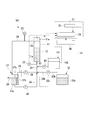
- the organic wastewater treatment apparatus 1 of the present embodiment stores an anaerobic microorganism 11 to which an anaerobic microorganism is attached and an anaerobic treatment reactor 11 through which treated water is passed.
- a microorganism adhesion amount determination mechanism 21 that determines the adhesion amount of anaerobic microorganisms
- a flow rate control mechanism 31 that controls the flow rate of treated water to the anaerobic treatment reactor 11, and an accelerator that promotes adhesion of anaerobic microorganisms to the carrier 12.
- a microorganism amount control mechanism 41 to be supplied.
- the processing apparatus 1 is provided with a supply path 33 and a discharge path 34 respectively connected to the anaerobic treatment reactor 11, and a circulation path 35 that bypasses the supply path 33 and the discharge path 34.
- the flow rate control mechanism 31 is provided with a raw water supply unit 32.
- raw water of treated water is sent from the raw water supply unit 32 to the anaerobic treatment reactor 11 via the supply path 33.
- the treated water that has been anaerobically treated in the anaerobic treatment reactor 11 is discharged to the discharge passage 34.
- a part of the treated water is returned to the supply path 33 via the circulation path 35, and the remaining treated water is discharged out of the system.
- the flow rate control mechanism 31 is operated to separate the microorganisms from the carrier 12.
- the microorganism amount control mechanism 41 is operated to attach the microorganisms to the carrier 12.
- the anaerobic treatment reactor 11 (hereinafter sometimes referred to as the reactor 11) is a hollow cylindrical container that stores the carrier 12.
- a treated water inflow port 11a is provided at the lower end of the reactor 11, and a treated water discharge port 11b is provided at the upper part.
- an exhaust port 11c for gas generated with anaerobic processing is provided at the upper end of the reactor 11.
- the reactor 11 stores a carrier 12 to which microorganisms are attached.
- the treated water is configured to flow from the lower part of the reactor 11 toward the upper part.
- the treated water introduced from the inflow port 11a is anaerobically treated by anaerobic microorganisms when passing through the carrier 12.
- the treated water that has passed through the carrier 12 is discharged to the outside from the discharge port 11b.
- the gas generated during the anaerobic treatment is discharged from the exhaust port 11c.
- the carrier 12 for example, various materials such as activated carbon, plastic, ceramic, carbon fiber, gel polymer, and the like are used.
- the shape include a spherical shape, a cylindrical shape, and a string shape.
- the filling amount of the carrier 12 in the reactor 11 in the anaerobic filter bed method in which the carrier 12 is fixed, is preferably 50% or more with respect to the inner volume of the reactor 11, and 60% or more. It is more preferable to make it 75% or more.
- the upper limit value of the filling amount is not particularly limited, but is 80%, for example.
- the filling amount is preferably between 30% and 80% with respect to the internal volume of the reactor 11 for the carrier flow, and between 40% and 70%. More preferably, it is more preferably between 55% and 60%.
- the microorganism adhesion amount determination mechanism 21 was measured by a pressure gauge 22 that measures the pressure of treated water on the inlet side of the reactor 11, a pressure gauge 23 that measures the pressure of treated water on the outlet side, and the pressure gauges 22, 23.
- An adhesion amount determination unit 24 that determines the amount of anaerobic microorganisms adhering to the carrier 12 based on the difference in water pressure is provided.
- the pressure gauge 22 is provided in the supply path 33 near the inlet 11a of the reactor 11 so that the water pressure of the treated water flowing into the reactor 11 can be measured.
- the pressure gauge 23 is provided in the discharge path 34 near the discharge port 11b of the reactor 11, and can measure the water pressure of the treated water discharged from the reactor 11.
- Each of the pressure gauges 22 and 23 is connected to an adhesion amount determination unit 24 via a signal line, and can output a measurement result to the adhesion amount determination unit 24.
- the adhesion amount determination unit 24 calculates the water pressure difference of the treated water on the inlet side and the outlet side of the reactor 11 based on the measured value of the water pressure output from the pressure gauges 22, 23, and applies to the carrier 12 based on the water pressure difference.
- the amount of attached anaerobic microorganisms is determined.
- the amount of microorganisms attached to the carrier 12 is small, the passage resistance of the treated water is low and the water pressure difference is small.
- the amount of microorganisms attached to the carrier 12 is large, the passage resistance of the treated water increases and the water pressure difference increases. By measuring the water pressure difference, the amount of microorganisms attached to the carrier 12 can be determined.
- a differential pressure determination value setting unit 25 is connected to the adhesion amount determination unit 24.
- data on the relationship between the water pressure difference and the microorganism adhesion amount is stored in advance for each flow rate of the treated water.
- the flow rate of treated water in the reactor 11 is X
- the amount of microorganisms attached is appropriate, and if the water pressure difference is less than P1, the amount of adhesion is There are few data, and when P2 is exceeded, there is data that the amount of adhesion is excessive.
- the lower limit value P1 and the upper limit value P2 of the appropriate range are output from the differential pressure determination value setting unit 25 to the adhesion amount determination unit 24 in accordance with the flow rate X in the reactor 11.
- the flow rate control mechanism 31 includes a raw water supply unit 32 that supplies raw water to the reactor 11, a raw water pump 32 c that sends raw water from the raw water supply unit 32 to the reactor 11, and treated water discharged from the reactor 11.
- a circulation pump 38 that returns a part to the reactor 11 through the supply path 33 and a flow rate adjusting unit 36 are configured.
- the flow rate control mechanism 31 adjusts the flow rates of raw water and circulating water passing through the reactor 11.
- the raw water supply unit 32 includes a raw water tank 32a that stores the raw water of the treated water, a raw water path 32b that sends the raw water from the raw water tank 32a to the supply path 33, and a raw water pump 32c that is provided in the middle of the raw water path 32b. ing.
- a raw water tank 32a wastewater discharged from a source of organic wastewater is stored.
- the raw water pump 32 c is connected to the flow rate adjustment unit 36 via a communication line or the like, and can adjust the supply flow rate of the raw water based on a command from the flow rate adjustment unit 36.
- a raw water path 32b, a circulation path 35, and a return path 39 described later are connected.
- the other end of the supply path 33 is connected to the inlet 11 a of the reactor 11.
- a separation tank 37 is provided in the middle of the discharge path 34. In the separation tank 37, a circulation path 35 is branched from the discharge path 34.
- a circulation pump 38 is provided in the middle of the circulation path 35. The circulation pump 38 is connected to the flow rate adjustment unit 36 via a communication line or the like, and can adjust the flow rate of the treated water flowing through the circulation path 35 based on a command from the flow rate adjustment unit 36.
- the separation tank 37 is disposed between the reactor 11 and the circulation pump 38, and a solid-liquid separation tank 37a for precipitating solids contained in the treated water, a supernatant water storage tank 37b, a solid-liquid separation tank 37a, and a supernatant.
- a partition plate 37c that partitions the water storage tank 37b is provided.
- the solid-liquid separation tank 37a is connected to a discharge path 34 for discharging the treated water out of the system of the processing apparatus 1.
- the connection position of the solid-liquid separation tank 37a and the discharge path 34 is a position substantially the same height as the upper end of the partition plate 37c.
- a circulation path 35 is connected to the supernatant water storage tank 37b.
- a return path 39 is connected to the bottom of the solid-liquid separation tank 37a.
- the other end of the return path 39 is connected to the supply path 33.
- a return pump 40 that operates based on a command from the flow rate adjusting unit 36 is provided. The solid content can be returned to the reactor 11 by the return path 39.
- the flow rate adjustment unit 36 controls the flow rate of the treated water flowing through the circulation path 35 by the circulation pump 38 based on the determination result of the adhesion amount determination unit 24, and controls the supply amount of the raw water flowing through the raw water channel 32b by the raw water pump 32c. Further, the supply amount of the accelerator is also controlled as necessary.
- the microorganism amount control mechanism 41 includes a promoter tank 42 in which the promoter is stored, and a promoter pump 44 that controls the amount of promoter supplied to the reactor 11 based on a command from the flow rate adjusting unit 36. ing.
- the accelerator tank 42 stores an accelerator that increases the amount of microorganisms attached to the carrier 12.
- AHL N-acyl-L-homoserine lactone
- quorum sensing promoters such as AHLs
- Gram-negative anaerobic bacteria can communicate with each other and release viscous substances from the cells. This viscous material promotes the formation of anaerobic bacteria biofilm on the carrier 12.
- the promoter is supplied to the reactor 11 via the promoter supply path 43.
- Organic wastewater collected from a source of organic wastewater is stored in the raw water tank 32a to be treated raw water.
- the raw water of the treated water stored in the raw water tank 32a flows into the supply channel 33 through the raw water channel 32b.
- treated water from the circulation path 35 also flows into the supply path 33.
- the treated water merged in the supply path 33 flows into the reactor 11 and is subjected to anaerobic treatment by anaerobic microorganisms attached to the surface of the carrier 12 in the reactor 11.
- the treated water after the anaerobic treatment is discharged from the reactor 11 to the discharge path 34.
- the gas generated in accordance with the anaerobic process is discharged to the outside of the reactor 11 through the exhaust port 11c.
- the treated water discharged to the discharge path 34 is solid-liquid separated in the solid-liquid separation tank 37a, and a part of the treated water is discharged again to the outside of the processing apparatus 1 through the discharge path 34.
- the remainder of the treated water flows as supernatant water over the partition plate 37c and into the supernatant water storage tank 37b.
- the supernatant water of the treated water that has flowed into the supernatant water storage tank 37 b is sent from the circulation path 35 to the supply path 33 by the circulation pump 38.
- the solid concentration of the treated water flowing into the circulation path 35 is reduced by the solid-liquid separation tank 37a.
- Biogas contains 60% or more of methane. Biogas is used as a heat source for boilers and an energy source for generators after gas treatment of corrosive components in biogas.
- the treatment efficiency of the anaerobic treatment can be improved by circulating the treated water and passing the water through the reactor 11 many times.
- the circulation flow rate and the raw water flow rate are set to appropriate flow rates according to the sedimentation and fluidity of the carrier 12 and the type of carrier. If the circulation flow rate and the raw water flow rate are appropriate flow rates, the carrier 12 flowing out from the reactor 11 is hardly generated, but biogas adheres to some of the carriers 12 and floats due to the lighter specific gravity of the carrier 12. .
- the floated carrier 12 is discharged from the reactor 11 through the discharge path 34 and then separated by a solid-liquid separation tank 37 a installed in the separation tank 37. Thereafter, when a certain amount of the carrier 12 is accumulated, it is returned to the reactor 11 through the return path 39.
- the pressure difference between the treated water on the entry side and the exit side of the reactor 11 is always measured by the pressure gauges 22 and 23. If the sum of the flow rate of the treated water flowing through the circulation path 35 and the flow rate of the raw water is constant and the amount of carrier and the amount of organisms inside the reactor 11 are constant, the pressure of the water pressure of the treated water on the inlet side and the outlet side of the reactor 11 The difference is constant. This pressure difference increases as the amount of biofilm adhering to the carrier 12 increases, and the pressure difference decreases as the amount of biofilm decreases. As long as the pressure difference of the treated water is within a predetermined range, normal operation can be continued.
- the adhesion amount determination unit 24 detects this, and the processing apparatus 1 operates normally.
- the case where the pressure difference deviates from the predetermined range is, for example, a case where the pressure difference is less than the lower limit value P1 or the upper limit value P2 of the appropriate range of the water pressure difference at the flow rate X.
- the adhesion amount determination unit 24 corresponds to the comparison result between the water pressure difference between the treated water on the inlet side and the outlet side of the reactor 11 and the lower limit value and the upper limit value of the water pressure difference preset in the differential pressure determination value setting unit 25. 2 operates according to the procedure shown in FIG.
- the adhesion amount determination unit 24 determines that “adhesion is excessive” and proceeds to step 2 to enter the cleaning process of the carrier 12.
- the adhesion amount determination unit 24 instructs the flow rate adjustment unit 36 to shift to the cleaning process.
- the flow rate adjusting unit 36 stops the raw water pump 32c of the raw water supply unit 32 and increases the flow rate of the circulation pump 38 from the normal flow rate. Thereby, the rising line flow velocity of the treated water in the reactor 11 is improved, and the detachment of microorganisms from the carrier 12 is promoted.
- the ascending linear flow rate necessary for detachment of microorganisms varies depending on the properties of the carrier 12, but the detachment can be achieved by operating for a predetermined time (about 1 to 10 minutes) at a flow rate more than 5 times the flow rate in the reactor 11 during normal operation. Is promoted.
- the peeled microorganisms are transported to the separation tank 37 together with the treated water as a solid content and stored in the bottom of the solid-liquid separation tank 37a. The stored solid content is finally discharged as sludge.
- the flow rate of the treated water flowing through the reactor 11 is set to the value before the start of washing. Return to standard. Thereafter, the water pressure difference is measured again. More specifically, with the raw water pump 32c stopped, the flow rate of the circulation pump 38 is adjusted so that the flow rate of the treated water flowing through the reactor 11 becomes the flow rate when the water pressure difference is measured before the start of cleaning. . Or you may restart the action
- the reason for controlling the flow rate in this way is that the water pressure difference between the inlet side and the outlet side of the reactor 11 is affected by the flow rate of the treated water, and therefore it is necessary to measure the water pressure difference at a constant flow rate.
- the adhesion amount determination unit 24 returns to Step 1 of FIG. 2 to measure the water pressure difference of the treated water between the inlet side and the outlet side of the reactor 11, and the water pressure difference of the treated water exceeds the upper limit value of the appropriate range. Re-determine whether or not.
- the process proceeds to step 2 again, and the treated water flow rate by the circulation pump 38 is increased to the same level as the first time or higher than the first time, The time carrier 12 is washed. In this manner, the operations of Step 1 and Step 2 are alternately repeated until the water pressure difference of the treated water becomes equal to or less than the upper limit value P2.
- the adhesion amount determination unit 24 proceeds to Step 3.
- the processing apparatus 1 returns to normal operation. Specifically, the supply amount of raw water and the circulation flow rate are returned to the normal operation state.
- Step 3 of FIG. 2 when the water pressure difference of the treated water between the inlet side and the outlet side of the reactor 11 becomes less than the lower limit value of the appropriate range. Then, the adhesion amount determination unit 24 determines that the adhesion amount of microorganisms to the carrier 12 is “insufficient adhesion”, and proceeds to step 5.
- the adhesion amount determination unit 24 instructs the flow rate adjustment unit 36 to shift to the adhesion promotion process.
- the flow rate adjustment unit 36 sets the raw water pump 32c and the circulation pump 38 to normal operation flow rates. Further, the flow rate adjusting unit 36 operates the promoter pump 44 to supply the promoter to the reactor 11 and promote biofilm adhesion to the carrier 12.
- the injection rate of AHL as an accelerator is preferably on the order of several micromoles / L to several nanomoles / L.
- the injection amount of AHL is very small compared to the flow rate of the raw water pump 32c and the flow rate of the circulation pump 38, the influence of the flow rate of the accelerator on the water pressure difference is almost negligible. Accordingly, the water pressure difference is continuously measured even during the injection of the accelerator, and when the water pressure difference exceeds the lower limit value of the appropriate range, the accelerator pump 44 is stopped and the adhesion promoting process is terminated. You may transfer to normal operation.
- the amount of anaerobic microorganisms attached to the carrier 12 is determined by the microorganism attachment amount determination mechanism 21.
- the result is transmitted from the adhesion amount determination unit 24 to the flow rate control mechanism 31, and the flow rate control mechanism 31 increases the flow rate of treated water to the reactor 11.
- the shear water is applied to the carrier by the treated water whose flow rate is increased, the microorganisms attached to the carrier 12 are removed, and the attached amount of microorganisms becomes an appropriate amount.
- the microorganism adhesion amount determination mechanism 21 determines that the microorganism adhesion amount is insufficient, the result is transmitted from the microorganism adhesion amount determination mechanism 21 to the microorganism amount control mechanism 41, and the microorganism amount control mechanism 41 is transferred to the carrier 12. Accelerating the adhesion of anaerobic microorganisms. Thereby, the amount of microorganisms adhering to the carrier 12 increases, and the amount of microorganisms attached becomes an appropriate amount.
- the amount of microorganisms attached to the carrier 12 is always appropriately determined by the flow rate control mechanism 31 or the microorganism amount control mechanism 41 based on the determination result of the microorganism adhesion amount determination mechanism 21. Since the amount is controlled, the treatment efficiency of the organic waste water can be kept constant.
- the microorganism adhesion amount determination mechanism 21 includes pressure gauges 22 and 23 and an adhesion amount determination unit 24, and the microorganism adhesion amount determination mechanism 21 supplies the carrier 12 to the carrier 12 based on the water pressure difference between the treated water on the inlet side and the outlet side of the reactor 11. Since the adhesion amount of anaerobic microorganisms is determined, the adhesion amount of microorganisms can be determined quickly and easily at any time.
- the adhesion amount determination unit 24 determines that the amount of microorganisms is an appropriate amount, the flow rate of raw water and the flow rate of treated water in the circulation path 35 are set to a steady state and normal operation is continued. .
- the flow rate of treated water flowing through the circulation path 35 is adjusted so that the flow rate of treated water flowing through the reactor 11 is always constant.
- the adhesion amount determination unit 24 determines that the microorganisms are excessive, the flow rate of the treated water flowing through the circulation path 35 is increased from the steady state by a command from the flow rate adjusting unit 36 to thereby increase the flow rate of the treated water in the reactor 11.
- the microorganisms are detached from the carrier, so that the amount of the microorganisms attached to the carrier becomes an appropriate amount.
- the adhesion amount determination unit 24 determines that the number of microorganisms is insufficient, by supplying an accelerator in accordance with a command from the flow rate adjustment unit 36, the microorganisms are grown and the amount of microorganisms attached to the carrier 12 is set to an appropriate amount.
- the flow rate adjustment unit 36 controls the flow rate of the treated water flowing through the circulation path 35, the supply amount of the raw water, and the supply amount of the promoter. The anaerobic treatment of the treated water can be carried out while maintaining an appropriate amount.
- the flow rate adjusting unit 36 always controls the total flow rate of the treated water flow rate, the raw water supply amount, and the promoter supply amount flowing through the circulation path 35 to be constant in the normal operation and maintenance operation microorganism attachment processes. Therefore, the adhesion amount of microorganisms can be appropriately monitored based on the water pressure difference between the inlet side and the outlet side of the anaerobic treatment reactor.
- the separation tank 37 in the middle of the discharge path 34, the microorganisms in the treated water discharged from the reactor 11 can be recovered as a solid content.
- the concentration of solids in the treated water can be reduced, and excess return of microorganisms to the reactor 11 can be prevented.
- the organic wastewater treatment apparatus 1 of the present embodiment is provided with a return path 39 for returning a part of the solid separated by the separation tank 37 to the reactor 11 via the supply path 33. .
- the solid content stored in the separation tank 37 is returned to the return path. 39 is returned to the reactor 11. Thereby, the amount of microorganisms in the reactor 11 can be quickly recovered, and the anaerobic treatment can be restarted at an early stage.
- microorganism amount control mechanism 41 is provided with an accelerator tank 42 and an accelerator pump 44, and based on the state of excess or deficiency of microorganisms notified from the microorganism adhesion amount determination unit 24 via the flow rate adjustment unit 36, Since the supply amount of the accelerator is controlled by the accelerator pump 44, the accelerator can be appropriately supplied.
- the microorganism amount control mechanism 41 of the present embodiment is configured to supply the promoter within a range not exceeding the upper limit of the processing load of the reactor 11.
- the microorganism is eutrophied and the quality of the treated water deteriorates rapidly. Therefore, in this embodiment, the accelerator is supplied so as not to exceed the upper limit of the processing load of the reactor 11. Thereby, the deterioration of the quality of the treated water by eutrophication can be prevented.
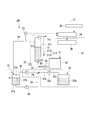
- the processing apparatus 101 of 2nd Embodiment differs from the processing apparatus 1 of the first embodiment in the type of accelerator stored in the promoter tank of the microorganism amount control mechanism.
- the structure of the processing apparatus of this embodiment is the same as the structure of the processing apparatus 1 of 1st Embodiment except that the kind of promoter is different. Therefore, in the following description, among the configurations of the processing apparatus 101 illustrated in FIG. 3, the same reference numerals are given to the same configurations as those of the processing apparatus 1 of the first embodiment, and description thereof is omitted.
- the processing apparatus 101 of this embodiment includes a reactor 11, a microorganism adhesion amount determination mechanism 21, a flow rate control mechanism 31, and a microorganism amount control mechanism 141 that supplies a promoter.
- the microorganism amount control mechanism 141 of the present embodiment includes a promoter tank 142 in which the promoter is stored, a promoter pump 44 that controls the amount of promoter supplied to the reactor 11 based on a command from the flow rate adjustment unit 36, Is provided.
- the accelerator tank 142 stores an accelerator that increases the amount of microorganisms attached to the carrier 12.
- a liquid mainly composed of carbohydrates or saccharides is used.
- emitted in a soft drink manufacturing process can be illustrated.
- a liquid having a chemical oxygen demand more than 10 times the chemical oxygen demand (CODcr) (organic concentration) of potassium dichromate in the raw water of the treated water is desirable.
- the cleaning process of the normal operation and the maintenance operation is the same as that of the first embodiment, and the operation of the adhesion promoting process is different from that of the first embodiment.
- the adhesion promotion process of this embodiment will be described.
- the adhesion amount of microorganisms to the carrier 12 is determined to be “adhesion insufficient”.
- the adhesion amount determination unit 24 instructs the flow rate adjustment unit 36 to shift to the adhesion promotion step.
- the flow rate adjusting unit 36 stops the raw water pump 32 c and operates the circulation pump 38 and the accelerator pump 44.
- the promoter pump 44 By actuating the promoter pump 44, the promoter is supplied to the reactor 11 to promote biofilm adhesion to the carrier 12.
- the supply flow rate of the promoter is set to be equal to or lower than the flow rate calculated by the following formula, and the adhesion of the biofilm is promoted with an organic load lower than the normal processing load.
- Qa, Qin, Sin and Sa in Formula 1 are as follows.
- Qa Accelerator supply flow [m 3 / min]
- Qin Flow rate of raw water during normal operation [m 3 / min]
- Sa Accelerator chemical oxygen demand (CODcr) [g / m 3 ]
- Sin Chemical oxygen demand of treated water (CODcr) [g / m 3 ]
- the operation flow rate of the circulation pump in this step is set as shown in the following equation (2) so that the flow rate of treated water on the entry side and the exit side of the reactor 11 is the same as the flow rate during normal operation. . If the flow rate of the treated water flowing into the reactor 11 is constant and the amount of biofilm in the reactor 11 is constant, the differential pressure becomes constant. Therefore, the amount of attached microbial membrane can be determined from the differential pressure.
- Qa_cir and Qcir in Equation 2 are as follows. Qin and Qa are the same as in equation (1).
- Qa_cir Circulation flow rate in the adhesion promotion process [m 3 / min]
- Qcir Circulation flow rate during normal operation [m 3 / min]
- the accelerator pump 44 is stopped and the operation of the raw water pump 32c is restarted. Further, the circulation flow rate is returned to the circulation flow rate in the normal operation, and the processing apparatus 101 is returned to the normal operation.
- the accelerator is introduced while monitoring the water pressure difference, and the reactor 11 flows to enable control to stop the injection of the accelerator when the water pressure difference falls within an appropriate range. It is necessary to set the flow rate of treated water to the same level as that of normal operation.
- the flow rate of the accelerator needs to be larger than that in the first embodiment. Therefore, in this embodiment, the flow rate of the treated water flowing through the circulation path 35 is adjusted according to the above equation (2). Thereby, it becomes possible to make the flow volume of the treated water etc. which flows through the reactor 11 comparable as the flow volume of normal driving
- the waste liquid is used as the accelerator, the cost of the accelerator can be suppressed.
- the timing of stopping the adhesion promotion process can be determined only by monitoring the water differential pressure Can be judged.
- a processing apparatus 201 according to the third embodiment will be described with reference to FIG.
- the reactor of the processing apparatus 201 shown in FIG. 4 is provided with a gas supply unit for stirring the carrier 12 with gas.
- the processing apparatus 201 is different from the processing apparatus 1 of the first embodiment.
- a gas supply unit is provided, the configuration of the processing apparatus of the present embodiment is the same as the configuration of the processing apparatus 1 of the first embodiment. Therefore, in the following description, among the configurations of the processing apparatus 201 illustrated in FIG. 4, the same reference numerals are given to the same configurations as the processing apparatus 1 of the first embodiment, and description thereof is omitted.
- the processing apparatus 201 of the present embodiment includes a reactor 211, a microorganism adhesion amount determination mechanism 21, a flow rate control mechanism 31, and a microorganism amount control mechanism 41 that supplies a promoter.
- the reactor 211 of this embodiment is provided with a gas supply unit 212.
- the gas supply unit 212 includes a bypass pipe 213 and a valve 214 provided in the middle of the bypass pipe 213.
- the bypass pipe 213 is a pipe for blowing a part of the biogas discharged from the exhaust port 11 c into the reactor 211 from the lower part of the reactor 211.
- the valve 214 may be a flow rate adjustment valve capable of adjusting the flow rate of the biogas flowing through the bypass pipe 213, or may be a shutoff valve capable of shutting off the supply of biogas.
- the valve 214 is connected to the flow rate adjustment unit 36 via a communication line or the like.
- the adhesion promotion process of the normal operation and the maintenance operation is the same as that of the first embodiment, and the operation of the cleaning process is different from that of the first embodiment.
- the cleaning process of this embodiment will be described.
- the adhesion amount of microorganisms to the carrier 12 is determined to be “excessive adhesion”.
- the adhesion amount determination unit 24 instructs the flow rate adjustment unit 36 to shift to the cleaning process.
- the flow rate adjusting unit 36 stops the raw water pump 32c of the raw water supply unit 32 and increases the flow rate of the circulation pump 38 from the flow rate during normal operation. Thereby, the rising line flow velocity of the treated water in the reactor 11 is improved, and the detachment of microorganisms from the carrier 12 is promoted.
- a command to open the valve 214 is issued from the flow rate adjusting unit 36, and biogas is blown from the lower part of the reactor 11 by the gas supply unit 212.
- the gas blowing part of the gas supply part 212 is a pipe having a plurality of holes, and the carrier 12 is washed by a bubble flow. After cleaning for several minutes (1 to 5 minutes), the valve 214 is closed. Thereafter, the processing device 201 is returned to the normal operation. The peeled solid content flows out of the reactor 11 and is collected in the separation tank 37.
- the present embodiment is not limited thereto.
- the inflow of treated water from the circulation path 35 to the reactor 11 is temporarily stopped, and biogas is blown from the gas supply unit 212 in the meantime to promote separation of the microbial membrane.
- the inflow of treated water from 35 may be resumed. In this manner, gas blowing and treatment water inflow may be alternately performed.
- the gas supplied by the gas supply unit 212 is not limited to biogas, and may be any kind of gas as long as it does not contain oxygen. Further, the gas supply unit 212 may be applied to the processing apparatus 101 of the second embodiment.
- gas is supplied from the gas supply unit into the reactor and the carrier 12 is agitated, whereby the microorganisms attached to the carrier 12 are separated. Can be promoted.
- the processing apparatus 301 of 4th Embodiment is demonstrated with reference to FIG.
- the imaging data of the carrier is used as an index for determining the amount of attached microorganisms, not the difference in water pressure of the treated water. That is, the processing apparatus 301 is different from the processing apparatus 1 of the first embodiment in the configuration of the microorganism adhesion amount determination mechanism.
- Other configurations of the processing apparatus 301 are the same as the configurations of the processing apparatus 1 of the first embodiment. In the following description, among the configurations of the processing apparatus 301 shown in FIG. 5, the same reference numerals are given to the same configurations as the processing apparatus 1 of the first embodiment, and description thereof is omitted.
- the processing apparatus 301 of the present embodiment includes the reactor 11, a microorganism adhesion amount determination mechanism 321, a flow rate control mechanism 31, and a microorganism amount control mechanism 41 that supplies an accelerator.
- the microorganism adhesion amount determination mechanism 321 of the present embodiment includes a sampling channel 322 that extracts a part of the carrier 12 from the reactor 11, an imaging device 323 that is provided in the sampling channel 322 and images the carrier 12, and an imaging device 323. And an adhesion amount determination unit 324 that determines the amount of anaerobic microorganisms adhering to the carrier 12 based on the analysis result.
- the sampling channel 322 is a pipe that guides the carrier 12 stored in the reactor 11 to the imaging device 323, and one end is connected to the side wall of the reactor 11 and the other end is connected to the supply channel 33.
- the sampling flow path 322 is provided with a shutoff valve 322a.
- the shut-off valve 322a is connected to the flow rate adjustment unit 36 via a communication line or the like.
- the sampling flow path 322 is provided with a sampling pump 322b.
- the sampling pump 322b is connected to the flow rate adjustment unit 324 via a communication line or the like.
- the sampling pump 322b operates while the shut-off valve 322a is released, and draws the carrier 12 into the sampling flow path 322.
- the sampling pump 322b only needs to be operated periodically. In consideration of the growth rate of microorganisms, the sampling pump 322b may be operated only for a time necessary for determination, for example, at intervals of several hours to one day.
- the imaging device 323 includes an imaging camera 323a and an image analysis unit 323b.
- the imaging camera 323a may capture either a still image or a moving image.
- the image analysis unit 323b analyzes the shape and color of several tens to several hundreds of carriers 12, and outputs the analysis result to the adhesion amount determination unit 324 via a communication line or the like.
- the image analysis unit 323b calculates a determination value for determining the amount of attached microorganisms. Examples of the determination value include the following two types of determination value a and determination value b.
- the image analysis unit 323b calculates the determination values a and b, and outputs the result to the adhesion amount determination unit 324.
- the determination value a is a determination value focusing on the change in the size of the carrier.
- the percentage of the number in which the size (diameter) of the carrier 12 with the microorganisms attached is 1 mm or more larger than the size of the original carrier 12 is defined as a judgment value a.
- the determination value b is a determination value focusing on the change in the color of the carrier.
- the percentage of the number of carriers that have changed to black due to the adhesion of microorganisms is taken as a judgment value b. As the amount of attached microorganisms increases, both the determination values a and b increase.
- the adhesion amount determination unit 324 determines the adhesion amount of the anaerobic microorganisms to the carrier 12 based on the determination values a and b output from the image analysis unit 323b.
- a determination value setting unit 325 is connected to the adhesion amount determination unit 324.
- the lower limit value and the upper limit value of the appropriate range of the determination value a or the determination value b are stored in advance, and these upper limit value and lower limit value are transferred from the determination value setting unit 325 to the adhesion amount determination unit 324. Is output.
- the determination value a when the determination value a is less than the lower limit value a1, it is determined that the amount of attached microorganisms is insufficient, and when the determination value a exceeds the upper limit value a2, the amount of attached microorganisms is determined to be excessive. Similarly, when the determination value b is less than the lower limit value b1, it is determined that the amount of attached microorganisms is insufficient, and when the determination value b exceeds the upper limit value b2, the amount of attached microorganisms is determined to be excessive.
- the lower limit value a1 of the determination value a using the size of the carrier 12 as an index can be set to 50%, for example, and the upper limit value a2 can be set to 80%, for example. Further, the lower limit value b1 of the determination value b using the change in the color of the carrier 12 as an index can be set to 50%, for example, and the upper limit value b2 can be set to 95%, for example.
- both determination values a and b may be used. Further, both determination values a and b may be output to the adhesion amount determination unit 324, and the determination value a may be used for determination of the lower limit value a1, and the determination value b may be used for determination of the upper limit value b2, or vice versa. Good.
- the determination frequency of the amount of adhered microorganisms may be set according to the operation time of the sampling pump 322b, and may be performed at intervals of several hours to one day, for example.
- the flow rate of the treated water is a flow rate (flow velocity) that is five times or more the normal operation flow rate (flow velocity) for a predetermined time (about 1 to 10 minutes). Just flow away.
- the carrier 12 is sampled and imaged again. If the determination value a or b is in an appropriate range, the processing device 301 returns to normal operation. If the determination value a or b exceeds the upper limit value, the cleaning process is performed again.
- an accelerator may be added as in the first embodiment. If the determination value a or b is in an appropriate range at the next sampling after adding the accelerator, the processing device 301 returns to normal operation. If the judgment value a or b is less than the lower limit value, the adhesion promoting step is performed again.
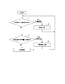
- FIG. 6 shows a control flow when the determination value a is used.
- step 1 when the determination value a exceeds the upper limit value a2, the adhesion amount determination unit 324 proceeds to step 2 to perform a cleaning process. After completion of the cleaning process, the adhesion amount determination unit 324 returns to Step 1 again, and if the determination value a exceeds the upper limit value a2, the process proceeds to Step 2 again to perform the cleaning process, and the determination value a is equal to or less than the upper limit value a2. If so, go to Step 3.
- step 3 if the determination value a is equal to or greater than the lower limit value a1, the adhesion amount determination unit 324 proceeds to step 4, and the processing device 301 returns from the maintenance operation to the normal operation.
- Step 3 if the determination value a is less than the lower limit value a1, the adhesion amount determination unit 324 proceeds to Step 5 and performs an adhesion promotion process. After completion of the adhesion promotion process, the adhesion amount determination unit 324 returns to Step 1 again. What is necessary is just to implement the above control flow.
- the amount of microorganisms attached to the carrier is determined by directly observing the carrier 12, the flow rate of the treated water in the reactor 11 at the time of determination is compared with a case where the difference in water pressure is determined as an index. There are few restrictions. Therefore, the determination of the amount of attached microorganisms can be performed at any time during normal operation or during maintenance operation. Therefore, in this embodiment, it is possible to determine the amount of adhesion even during the cleaning process or the adhesion promotion process.
- the amount of anaerobic microorganisms attached to the carrier 12 is determined based on the imaging result of the carrier 12, the amount of microorganisms attached can be determined quickly and easily at any time.
- microorganism adhesion amount determination mechanism 321 of the present embodiment may be applied to the second embodiment or the third embodiment.
- the amount of microorganisms attached to the carrier can always be controlled to an appropriate amount by the flow rate control mechanism or the microorganism amount control mechanism based on the determination result of the microorganism adhesion amount determination mechanism. Thereby, the processing efficiency of organic waste water can be maintained constant.
Landscapes
- Life Sciences & Earth Sciences (AREA)
- Microbiology (AREA)
- Biodiversity & Conservation Biology (AREA)
- Hydrology & Water Resources (AREA)
- Engineering & Computer Science (AREA)
- Environmental & Geological Engineering (AREA)
- Water Supply & Treatment (AREA)
- Chemical & Material Sciences (AREA)
- Organic Chemistry (AREA)
- Purification Treatments By Anaerobic Or Anaerobic And Aerobic Bacteria Or Animals (AREA)
- Micro-Organisms Or Cultivation Processes Thereof (AREA)
- Biological Treatment Of Waste Water (AREA)
Abstract
実施形態の有機性排水の処理装置は、嫌気処理リアクタと、微生物付着量判定機構と、流量制御機構と、微生物量制御機構とを持つ。嫌気処理リアクタにおいては、嫌気性微生物を付着させる担体が貯留され、かつ処理水が通水される。微生物付着量判定機構は、担体に対する嫌気性微生物の付着量を判定する。流量制御機構は、微生物付着量判定部の判定結果に基づき、嫌気処理リアクタに対する処理水の流量を制御する。微生物量制御機構は、微生物付着量判定部の判定結果に基づき、担体への嫌気性微生物の付着を促進させる促進剤を嫌気処理リアクタに供給する。
Description
本発明の実施形態は、有機性排水の処理装置に関する。
従来、有機性排水を浄化処理する手段として、経済性の観点より微生物による処理が多く用いられている。大別すると、酸素を必要としない嫌気性微生物を利用する嫌気処理と酸素必要とする好気微生物を利用する好気処理に分けられる。一般に嫌気処理には、以下のメリットがある。
・有機汚濁物質を分解する際に酸素を必要としない嫌気性微生物により水処理を行うため、水中に空気を送り込む動力が不要である。そのため、嫌気処理は、好気微生物を利用した処理方法よりも低コストで処理できる。
・好気微生物は有機物1g除去あたり約0.4~0.6g増殖するのに対し、嫌気性微生物は有機物1g除去あたり約0.1g程度の増殖であることから、有機物除去あたりの汚泥発生量を大幅に削減できる。
・有機物をメタン生成菌の働きでメタンまで分解するため、出てきた発生ガスからのエネルギー回収が可能である。
・好気微生物は有機物1g除去あたり約0.4~0.6g増殖するのに対し、嫌気性微生物は有機物1g除去あたり約0.1g程度の増殖であることから、有機物除去あたりの汚泥発生量を大幅に削減できる。
・有機物をメタン生成菌の働きでメタンまで分解するため、出てきた発生ガスからのエネルギー回収が可能である。
一方で、嫌気性微生物は好気微生物に比べ、一般的に増殖が遅く、有機物の摂取速度が遅いことから、嫌気処理には以下のデメリットがある。
・水処理の立上げに時間がかかる。
・一旦、系外に微生物が流出すると、処理の回復に時間がかかる。
・菌体あたりの有機物除去量は好気微生物よりも少なく、リアクタ内に多くの微生物を確保する必要がある。
・一旦、系外に微生物が流出すると、処理の回復に時間がかかる。
・菌体あたりの有機物除去量は好気微生物よりも少なく、リアクタ内に多くの微生物を確保する必要がある。
嫌気性微生物を利用した処理方法としては、嫌気性ろ床法、上向流式嫌気汚泥床法(Upflow Anaerobic Sludge Blanket,以下UASB法という)、膨張粒状汚泥床法(Expand Granular Sludge Blanket,以下EGSB法という)、嫌気流動床法などがある。
これらの方法は、嫌気性微生物をできるだけ反応リアクタ内に多く確保するために開発されたものであり、以下の2つに大別される。一つは、UASB法やEGSB法のように嫌気性微生物が集積し、自己造粒作用によって造粒したグラニュールを利用した処理方式である。もう一つは、嫌気性ろ床法や嫌気流動床法のように微生物を保持するための担体に嫌気性微生物を付着させて処理する処理方式である。
後者の処理方式の担体としては、活性炭、プラスチック、セラミック、炭素繊維、ゲル状のポリマー等様々なものが用いられる。形状としては、球状、円柱状、ひも状などがあり、また、微生物の付着面が大きくなるように表面が加工された担体が用いられる場合も多い。
前者のグラニュールを利用した処理方式に関しては、担体を利用しないため、初期コストが安価であるというメリットがある。一方、原水の条件によっては、造粒したグラニュールの崩壊、小粒化が発生する。これにより、微生物がリアクタから流出し、処理が悪化する場合がある。
また、後者の担体を利用した処理方式に関しては、担体に微生物を担持しているために付着量を適正管理すれば、安定処理が可能であり、かつ廃水種類の適用性が広いというメリットがある。
担体を利用した処理方式において、安定処理を実現するためには、担体に付着している生物量を適正管理する必要がある。担体への過剰な生物膜の付着は、処理水の濁度低下の要因になる。また、生物の付着過剰により水の流れが不均一になり、担体と被処理液の接触効率が低下し、有機物除去性能が低下する場合がある。一方で、付着している生物膜量が不十分であると、生物の絶対量が不足するため、有機物の処理性能が悪化する。
しかしながら担体への生物膜の付着状況の確認は容易ではなく、従来は、処理悪化を招いてから初めて、生物膜の適正な付着量のための対処を行う場合があった。
本発明が解決しようとする課題は、担体への生物膜の付着量を適切に制御することができる有機性排水の処理装置を提供することである。
実施形態の有機性排水の処理装置は、嫌気処理リアクタと、微生物付着量判定機構と、流量制御機構と、微生物量制御機構とを持つ。
嫌気処理リアクタにおいては、嫌気性微生物を付着させる担体が貯留され、かつ処理水が通水される。
微生物付着量判定機構は、担体に対する嫌気性微生物の付着量を判定する。
流量制御機構は、微生物付着量判定部の判定結果に基づき、嫌気処理リアクタに対する処理水の流量を制御する。
微生物量制御機構は、微生物付着量判定部の判定結果に基づき、担体への嫌気性微生物の付着を促進させる促進剤を嫌気処理リアクタに供給する。
嫌気処理リアクタにおいては、嫌気性微生物を付着させる担体が貯留され、かつ処理水が通水される。
微生物付着量判定機構は、担体に対する嫌気性微生物の付着量を判定する。
流量制御機構は、微生物付着量判定部の判定結果に基づき、嫌気処理リアクタに対する処理水の流量を制御する。
微生物量制御機構は、微生物付着量判定部の判定結果に基づき、担体への嫌気性微生物の付着を促進させる促進剤を嫌気処理リアクタに供給する。
以下、実施形態の有機性排水の処理装置を、図面を参照して説明する。
(第1の実施形態)
本実施形態の有機性排水の処理装置1は、図1に示すように、嫌気性微生物を付着させる担体12が貯留され、かつ処理水が通水される嫌気処理リアクタ11と、担体12への嫌気性微生物の付着量を判定する微生物付着量判定機構21と、嫌気処理リアクタ11に対する処理水の流量を制御する流量制御機構31と、嫌気性微生物の担体12への付着を促進させる促進剤を供給する微生物量制御機構41と、から構成されている。また、処理装置1には、嫌気処理リアクタ11にそれぞれ接続された供給路33及び排出路34と、供給路33と排出路34をバイパスする循環路35とが備えられている。さらに、流量制御機構31には、原水供給部32が備えられている。
本実施形態の有機性排水の処理装置1は、図1に示すように、嫌気性微生物を付着させる担体12が貯留され、かつ処理水が通水される嫌気処理リアクタ11と、担体12への嫌気性微生物の付着量を判定する微生物付着量判定機構21と、嫌気処理リアクタ11に対する処理水の流量を制御する流量制御機構31と、嫌気性微生物の担体12への付着を促進させる促進剤を供給する微生物量制御機構41と、から構成されている。また、処理装置1には、嫌気処理リアクタ11にそれぞれ接続された供給路33及び排出路34と、供給路33と排出路34をバイパスする循環路35とが備えられている。さらに、流量制御機構31には、原水供給部32が備えられている。
図1に示す処理装置1においては、処理水の原水が原水供給部32から供給路33を介して嫌気処理リアクタ11に送られる。嫌気処理リアクタ11において嫌気処理された処理水が排出路34に排出される。処理水の一部が循環路35を介して供給路33に戻され、処理水の残部は系外に排出される。また、微生物付着量判定機構21の判定結果に基づき、担体12への微生物の付着量が過剰な場合は流量制御機構31を作動させて担体12から微生物を剥離させる。微生物の付着量が不足する場合は微生物量制御機構41を作動させて担体12に微生物を付着させる。以下、処理装置1の構成について詳細に説明する。
嫌気処理リアクタ11(以下、リアクタ11という場合がある)は、担体12を貯留する中空筒状の容器である。リアクタ11の下端に処理水の流入口11aが設けられ、上部に処理水の排出口11bが設けられている。また、リアクタ11の上端には嫌気処理に伴って発生したガスの排気口11cが設けられている。リアクタ11には、微生物を付着させる担体12が貯留されている。処理水は、リアクタ11の下部から上部に向けて流れるように構成されている。流入口11aから流入された処理水は、担体12を通過する際に嫌気性微生物によって嫌気処理される。担体12を通過した処理水は排出口11bから外部に排出される。嫌気処理時に発生したガスは、排気口11cから排出される。
担体12としては、例えば、活性炭、プラスチック、セラミック、炭素繊維、ゲル状のポリマー等様々なものが用いられる。形状としては、球状、円柱状、ひも状などが例示される。また、微生物の付着面が大きくなるように表面が加工された担体12を用いることが好ましい。
リアクタ11内の担体12の充填量に関しては、担体12を固定化して使う嫌気ろ床法の場合は、充填量をリアクタ11の内容積に対して50%以上にすることが好ましく、60%以上にすることがより好ましく、75%以上にすることがより好ましい。なお、充填量の上限値は特に限定されないが、例えば80%である。担体を流動させて使う流動床法の場合は、担体流動のために充填量をリアクタ11の内容積に対して30%~80%の間にすることが好ましく、40%~70%の間にすることがより好ましく、55%~60%の間にすることがより好ましい。
微生物付着量判定機構21は、リアクタ11の入側における処理水の水圧を測定する圧力計22と、出側における処理水の水圧を測定する圧力計23と、圧力計22、23によって測定された水圧の差に基づいて担体12への嫌気性微生物の付着量を判定する付着量判定部24と、が備えられている。
圧力計22は、リアクタ11の流入口11a近くの供給路33に備えられており、リアクタ11に流入する処理水の水圧を測定できるようになっている。また、圧力計23は、リアクタ11の排出口11b近くの排出路34に備えられており、リアクタ11から排出される処理水の水圧を測定できるようになっている。各圧力計22、23は、信号回線を介して付着量判定部24に接続されており、測定結果を付着量判定部24に出力できるようになっている。
付着量判定部24は、圧力計22、23から出力された水圧の測定値に基づき、リアクタ11の入側及び出側における処理水の水圧差を算出し、この水圧差に基づき、担体12への嫌気性微生物の付着量を判定する。担体12への微生物の付着量が少ないと、処理水の通過抵抗が低くなり、水圧差が小さくなる。一方、担体12への微生物の付着量が多いと、処理水の通過抵抗が高くなり、水圧差が高まる。水圧差を計測することで、担体12への微生物の付着量を判定できる。
また、付着量判定部24には、差圧判定値設定部25が接続されている。差圧判定値設定部25には、水圧差と微生物付着量との関係のデータが処理水の流量別に予め記憶されている。このデータとしては、例えば、リアクタ11における処理水の流量がXである場合に、水圧差がP1~P2の範囲内であれば微生物の付着量は適切であり、水圧差がP1未満では付着量が少なく、P2を超えている場合は付着量が過剰であるといったデータが挙げられる。リアクタ11における流量Xに応じて、適正範囲の下限値P1及び上限値P2が差圧判定値設定部25から付着量判定部24に出力される。
次に、流量制御機構31は、リアクタ11に処理水の原水を供給する原水供給部32と、原水供給部32からリアクタ11に原水を送る原水ポンプ32cと、リアクタ11から排出された処理水の一部を、供給路33を介してリアクタ11に戻す循環ポンプ38と、流量調整部36と、から構成されている。
流量制御機構31は、リアクタ11を通過する原水と循環水の流量を調整する。
流量制御機構31は、リアクタ11を通過する原水と循環水の流量を調整する。
原水供給部32は、処理水の原水を貯留する原水槽32aと、原水槽32aから供給路33に原水を送る原水路32bと、原水路32bの途中に設けられた原水ポンプ32cとから構成されている。原水槽32aには、有機性排水の発生源から排出された排水が貯留される。原水ポンプ32cは、通信回線等を介して流量調整部36に接続されており、流量調整部36の指令に基づき原水の供給流量を調整できるようになっている。
供給路33の一端には、原水路32bと、循環路35と、後述する返送路39とが接続されている。また、供給路33の他端は、リアクタ11の流入口11aに接続されている。この構成により、原水供給部32から供給された原水と、循環路35から供給された処理水とが供給路33において合流され、リアクタ11に供給できるようになっている。
排出路34の一端は、リアクタ11の排出口11bに接続されている。また、排出路34の途中には、分離槽37が備えられている。この分離槽37において、排出路34から循環路35が分岐されている。循環路35の途中には、循環ポンプ38が備えられている。循環ポンプ38は、通信回線等を介して流量調整部36に接続されており、流量調整部36の指令に基づき循環路35を流れる処理水の流量を調整できるようになっている。
分離槽37は、リアクタ11と循環ポンプ38の間に配置されており、処理水に含まれる固形分を沈降させる固液分離槽37aと、上澄み水貯留槽37bと、固液分離槽37a及び上澄み水貯留槽37bを仕切る仕切り板37cとが備えられている。固液分離槽37aには、処理水を処理装置1の系外に排出する排出路34が接続されている。固液分離槽37aと排出路34の接続位置は、仕切り板37cの上端とほぼ同じ高さの位置である。また、上澄み水貯留槽37bには循環路35が接続されている。
固液分離槽37aの底部には、返送路39の一端が接続されている。返送路39の他端は、供給路33に接続されている。返送路39の途中には、流量調整部36の指令に基づき作動する返送ポンプ40が備えられている。返送路39によって、固形分をリアクタ11に返送できるようになっている。
流量調整部36は、付着量判定部24の判定結果に基づき、循環ポンプ38によって循環路35を流れる処理水の流量を制御し、原水ポンプ32cによって原水路32bを流れる原水の供給量を制御し、更に必要に応じて、促進剤の供給量をも制御する。
微生物量制御機構41には、促進剤が貯留される促進剤タンク42と、流量調整部36の指令に基づいてリアクタ11への促進剤の供給量を制御する促進剤ポンプ44と、が備えられている。
促進剤タンク42には、担体12に対する微生物の付着量を増大させる促進剤が貯留されている。促進剤としては、クオラムセンシング促進剤であるAHL(N-アシル-L-ホモセリンラクトン)類を用いることが好ましい。AHL類のようなクオラムセンシング促進剤を用いることで、グラム陰性の嫌気性菌の相互コミュニケーションが活発となり、菌体からの粘性物質の放出が促進される。この粘性物質によって、担体12への嫌気性菌バイオフィルムの形成が促進される。促進剤は、促進剤供給路43を経由してリアクタ11に供給される。
次に、図1に示す処理装置1の動作を説明する。本実施形態の処理水の動作は、通常運転と、保守運転に分けられる。以下、各動作について説明する。
まず、通常運転について説明する。
通常運転では、流量調整部36からの指令に基づいて原水供給部32の原水ポンプ32c及び循環ポンプ38が運転状態になっている。一方、返送ポンプ40及び促進剤ポンプ44は停止状態になっている。
通常運転では、流量調整部36からの指令に基づいて原水供給部32の原水ポンプ32c及び循環ポンプ38が運転状態になっている。一方、返送ポンプ40及び促進剤ポンプ44は停止状態になっている。
有機性排水の発生源から集められた有機性排水は、原水槽32aに貯留されて処理水の原水とされる。原水槽32aに貯留された処理水の原水は、原水路32bを通って供給路33に流入する。また、供給路33には、循環路35からの処理水も流入する。供給路33において合流した処理水はリアクタ11に流入し、リアクタ11内の担体12表面に付着した嫌気性微生物によって嫌気処理がなされる。嫌気処理後の処理水は、リアクタ11から排出路34に排出される。嫌気処理に伴って発生したガスは、排気口11cからリアクタ11の外部に排出される。
排出路34に排出された処理水は、固液分離槽37aにおいて固液分離され、処理水の一部は再び排出路34を通って処理装置1の系外に排出される。処理水の残部は上澄み水として仕切り板37cを越えて上澄み水貯留槽37bに流入される。上澄み水貯留槽37bに流入した処理水の上澄み水は、循環ポンプ38によって循環路35から供給路33に送られる。固液分離槽37aによって、循環路35に流入する処理水の固形分濃度が低減される。
処理水中の有機物は、リアクタ11中の担体12に付着した嫌気性菌の働きにより、メタンと二酸化炭素まで分解されてバイオガスとなる。発生したバイオガスは排気口11cから排出される。バイオガスはメタンを60%以上含有するものである。バイオガスは、バイオガス中の腐食性成分のガス処理をした後に、ボイラの熱源や発電機のエネルギー源として利用される。
原水の供給とともに循環路35によって処理水を循環させることで、リアクタ11における処理水の通水量を増大させて、リアクタ11内で担体12を流動させる。担体12を流動させることで、嫌気処理が効率よく行なわれ、また、担体12同士の凝集が防止される。更に、処理水を循環させてリアクタ11に何度も通水させることで、嫌気処理の処理効率が高められる。
循環流量及び原水の流量は、担体12の沈降性と流動性や担体の種類等に応じて、適正な流量に設定される。循環流量及び原水の流量が適正流量であれば、リアクタ11から流出する担体12はほとんど発生しないが、一部の担体12にはバイオガスが付着し、担体12の比重が軽くなることにより浮上する。この浮上した担体12は、排出路34によってリアクタ11から排出された後、分離槽37に設置された固液分離槽37aにより分離される。その後、ある程度の量の担体12が溜められたところで返送路39を介してリアクタ11に戻される。
通常運転の間、圧力計22、23によってリアクタ11の入り側及び出側での処理水の水圧差が常に計測される。循環路35を流れる処理水の流量と原水の流量との和が一定であり、リアクタ11内部の担体量・生物量が一定であれば、リアクタ入側と出側での処理水の水圧の圧力差は一定である。担体12に付着する生物膜量が多くなるとこの圧力差は上昇し、生物膜量が少なくなると圧力差は低下する。処理水の圧力差が所定の範囲にある限り、通常運転を続けることができる。
次に、保守運転について説明する。
リアクタ11の入側での処理水の水圧と出側での処理水の水圧との圧力差が所定の範囲から外れた場合、付着量判定部24がこれを検知し、処理装置1は通常運転から保守運転に移行する。圧力差が所定の範囲から外れた場合とは、例えば流量Xにおける水圧差の適正範囲の下限値P1未満になるか、上限値P2を超える場合である。
リアクタ11の入側での処理水の水圧と出側での処理水の水圧との圧力差が所定の範囲から外れた場合、付着量判定部24がこれを検知し、処理装置1は通常運転から保守運転に移行する。圧力差が所定の範囲から外れた場合とは、例えば流量Xにおける水圧差の適正範囲の下限値P1未満になるか、上限値P2を超える場合である。
付着量判定部24は、リアクタ11の入側と出側の処理水の水圧差と、差圧判定値設定部25にあらかじめ設定された水圧差の下限値及び上限値との比較結果に応じて、図2に示す手順で動作する。
図2のステップ1において、水圧差が適正範囲の上限値P2を超えた場合は、付着量判定部24が「付着過剰」と判断してステップ2に進み、担体12の洗浄工程に入る。
ステップ2における担体12の洗浄工程では、まず、付着量判定部24が流量調整部36に対して洗浄工程に移行するように指令する。流量調整部36は、原水供給部32の原水ポンプ32cを停止させるとともに、循環ポンプ38の流量を通常の流量より増大させる。これにより、リアクタ11内の処理水の上昇線流速を向上させて、担体12からの微生物の剥離を促進させる。
微生物の剥離に必要な上昇線流速は担体12の性状により異なるが、通常運転時のリアクタ11における流速に対して、5倍以上の流速で所定時間(1~10分程度)運転することで剥離が促進される。剥離された微生物は固形分として処理水とともに分離槽37に搬送され、固液分離槽37aの底部に貯留される。貯留された固形分は最終的に、汚泥として排出処理される。
循環ポンプ38の流量を通常運転量より増大させてから所定時間の経過後、水圧差が適切な範囲内に戻ったかどうかを確認するために、リアクタ11を流れる処理水の流量を洗浄開始前の水準に戻す。その後、水圧差の再測定を行う。より具体的には、原水ポンプ32cを停止させたまま、リアクタ11を流れる処理水の流量が、洗浄開始前に水圧差を測定した際の流量になるように、循環ポンプ38の流量を調整する。あるいは、原水ポンプ32cの作動を再開させ、循環ポンプ38の流量及び原水ポンプ32cの流量を洗浄開始前の水準に戻してもよい。
このように流量を制御する理由は、リアクタ11の入り側と出側の水圧差が処理水の流量の影響を受けるため、一定の流量で水圧差を測定する必要があるためである。
次いで、付着量判定部24は図2のステップ1に戻り、リアクタ11の入側と出側の間における処理水の水圧差を計測し、処理水の水圧差が適正範囲の上限値を超えているかどうかを再判定する。
ステップ1において処理水の水圧差が適正範囲の上限値P2より高い場合は、再びステップ2に進み、循環ポンプ38による処理水の流量を1回目と同程度若しくは1回目よりも上昇させて、所定時間担体12の洗浄工程を行う。このように、処理水の水圧差が上限値P2以下になるまで、ステップ1とステップ2の動作を交互に繰り返す。
ステップ1において処理水の水圧差が適正範囲の上限値P2より高い場合は、再びステップ2に進み、循環ポンプ38による処理水の流量を1回目と同程度若しくは1回目よりも上昇させて、所定時間担体12の洗浄工程を行う。このように、処理水の水圧差が上限値P2以下になるまで、ステップ1とステップ2の動作を交互に繰り返す。
一方、ステップ1において処理水の水圧差が適正範囲の上限値P2以下であった場合は、付着量判定部24はステップ3に進む。ステップ3において処理水の水圧差が適正範囲の下限値P1以上であった場合は、付着量判定部24はステップ4に進んで、処理装置1は通常運転に復帰する。具体的には、原水の供給量及び循環流量を通常運転の状態に戻す。
次に、洗浄工程の終了後、または通常運転中に、図2のステップ3において、リアクタ11の入側と出側の間における処理水の水圧差が適正範囲の下限値未満になった場合は、付着量判定部24は、担体12に対する微生物の付着量が「付着不足」であると判断し、ステップ5に進む。
ステップ5においては、付着量判定部24が流量調整部36に対して付着促進工程に移行することを指令する。流量調整部36は、原水ポンプ32c及び循環ポンプ38を通常運転の流量にする。また、流量調整部36は、促進剤ポンプ44を作動させて、促進剤をリアクタ11に供給し、担体12への生物膜付着を促進する。促進剤であるAHLの注入率は、数マイクロモル/L~数ナノモル/Lのオーダーであることが望ましい。付着促進工程の終了後、付着量判定部24はステップ1に戻り、制御フローを継続する。
なお、AHLの注入量は、原水ポンプ32cの流量や循環ポンプ38の流量に比べ非常に少量であるため、促進剤の流量が水圧差に与える影響はほとんど無視できる。従って、促進剤の注入中も水圧差を継続して測定し、水圧差が適正範囲の下限値を超えた時点で、促進剤ポンプ44を停止させて付着促進工程を終了し、処理装置1は通常運転に移行してもよい。
以上説明したように、嫌気性微生物が担体12に過剰に付着していると、リアクタ11における処理水の通水量が低下して処理効率が低下するか、または、担体12の層を通過する処理水の通水箇所が特定の箇所に限定されてしまう。その結果、担体12の全体を嫌気処理に利用できなくなる。一方、担体12への嫌気性微生物の付着量が不足すると、処理効率が低下する。
そこで、本実施形態の有機性排水の処理装置1では、微生物付着量判定機構21により、担体12に対する嫌気性微生物の付着量が判定される。付着量が過剰と判定された場合は、その結果が付着量判定部24から流量制御機構31に伝達され、流量制御機構31はリアクタ11に対する処理水の流量を増大させる。流量が増大された処理水によって担体に剪断応力が印加され、担体12に付着された微生物が除去され、微生物の付着量が適量になる。
一方、微生物付着量判定機構21によって微生物の付着量が不足すると判定された場合は、その結果が微生物付着量判定機構21から微生物量制御機構41に伝達され、微生物量制御機構41は担体12への嫌気性微生物の付着を促進させる促進剤を供給する。これにより、担体12に付着する微生物量が増大し、微生物の付着量が適量になる。
このように本実施形態の処理装置1によれば、微生物付着量判定機構21の判定結果に基づき、流量制御機構31または微生物量制御機構41によって、担体12への微生物の付着量を常に適切な量に制御するので、有機性排水の処理効率を一定に維持することができる。
また、微生物付着量判定機構21には、圧力計22、23と付着量判定部24とが備えられており、リアクタ11の入側及び出側における処理水の水圧差に基づいて担体12への嫌気性微生物の付着量を判定するので、いつでも迅速かつ容易に、微生物の付着量を判定できる。
また、本実施形態の処理装置1では、付着量判定部24において微生物が適量と判定された場合は、原水の流量と循環路35における処理水の流量を定常状態にして、通常運転を継続する。原水の供給量が変動する場合は、循環路35を流れる処理水の流量を調整して、リアクタ11を流れる処理水の通水量を常に一定にする。
付着量判定部24において微生物が過剰と判定された場合は、流量調整部36の指令により循環路35を流れる処理水の流量を定常状態よりも増大させることで、リアクタ11における処理水の通水量を増大させ、微生物を担体から剥離させて、担体への微生物の付着量を適量にする。
付着量判定部24において微生物が不足と判定された場合は、流量調整部36からの指令により促進剤を供給させることで、微生物を増殖させて、担体12への微生物の付着量を適量にする。
以上のように、付着量判定部24の判定結果に基づき、流量調整部36が、循環路35を流れる処理水の流量、原水の供給量、及び促進剤の供給量を制御するので、微生物の量を適量に維持しながら処理水の嫌気処理を進めることができる。
付着量判定部24において微生物が過剰と判定された場合は、流量調整部36の指令により循環路35を流れる処理水の流量を定常状態よりも増大させることで、リアクタ11における処理水の通水量を増大させ、微生物を担体から剥離させて、担体への微生物の付着量を適量にする。
付着量判定部24において微生物が不足と判定された場合は、流量調整部36からの指令により促進剤を供給させることで、微生物を増殖させて、担体12への微生物の付着量を適量にする。
以上のように、付着量判定部24の判定結果に基づき、流量調整部36が、循環路35を流れる処理水の流量、原水の供給量、及び促進剤の供給量を制御するので、微生物の量を適量に維持しながら処理水の嫌気処理を進めることができる。
また、流量調整部36は、通常運転及び保守運転の微生物の付着工程において、循環路35を流れる処理水の流量、原水の供給量、及び促進剤の供給量の合計流量を常時一定に制御するので、嫌気処理リアクタの入側と出側での水圧差に基づき、微生物の付着量を適切に監視できる。
また、排出路34の途中に分離槽37を設けることで、リアクタ11から排出された処理水中の微生物を固形分として回収できる。また、上澄みの一部を循環路35に送ることで、処理水中の固形分の濃度を低減でき、リアクタ11への微生物の余分な返送を防止できる。
また、本実施形態の有機性排水の処理装置1には、分離槽37によって分離された固形分の一部を、供給路33を介してリアクタ11に戻すための返送路39が備えられている。担体12への微生物の付着量が不足する場合、または担体12自体が不足する場合であって、促進剤による微生物の増殖に時間を要する場合は、分離槽37に溜められた固形分を返送路39によってリアクタ11に返送させる。これにより、リアクタ11内の微生物量を迅速に回復させ、早期に嫌気処理を再開させることができる。
また、微生物量制御機構41には、促進剤タンク42と促進剤ポンプ44とが備えられ、流量調整部36を介して微生物付着量判定部24から通知された微生物の過不足の状況に基づき、促進剤ポンプ44によって促進剤の供給量を制御するので、促進剤を適切に供給できる。
なお、本実施形態の微生物量制御機構41は、リアクタ11の処理負荷の上限を超えない範囲で促進剤を供給するように構成されている。促進剤の供給量がリアクタ11の処理負荷の上限を超えると、微生物にとって富栄養化された状態になり、処理水の水質が急速に悪化してしまう。そこで本実施形態では、リアクタ11の処理負荷の上限を超えないように促進剤を供給する。これにより、富栄養化による処理水の水質の悪化を防止できる。
(第2の実施形態)
次に、第2の実施形態の処理装置101について図3を参照して説明する。図3に示す処理装置101は、微生物量制御機構の促進剤タンクに貯留される促進剤の種類が、第1の実施形態の処理装置1と異なっている。促進剤の種類が異なること以外は、本実施形態の処理装置の構成は第1の実施形態の処理装置1の構成と同一である。そこで、以下の説明では、図3に示す処理装置101の構成のうち、第1の実施形態の処理装置1と同一の構成には同一の符号を付してその説明を省略する。
次に、第2の実施形態の処理装置101について図3を参照して説明する。図3に示す処理装置101は、微生物量制御機構の促進剤タンクに貯留される促進剤の種類が、第1の実施形態の処理装置1と異なっている。促進剤の種類が異なること以外は、本実施形態の処理装置の構成は第1の実施形態の処理装置1の構成と同一である。そこで、以下の説明では、図3に示す処理装置101の構成のうち、第1の実施形態の処理装置1と同一の構成には同一の符号を付してその説明を省略する。
本実施形態の処理装置101は、リアクタ11と、微生物付着量判定機構21と、流量制御機構31と、促進剤を供給する微生物量制御機構141と、から構成されている。本実施形態の微生物量制御機構141は、促進剤が貯留される促進剤タンク142と、流量調整部36の指令に基づいてリアクタ11への促進剤の供給量を制御する促進剤ポンプ44と、が備えられている。
促進剤タンク142には、担体12に対する微生物の付着量を増大させる促進剤が貯留されている。本実施形態の促進剤には、炭水化物または糖類を主成分とする液が用いられる。例えば清涼飲料製造工程で排出される廃液等を例示できる。処理水の原水の二クロム酸カリウムによる化学的酸素要求量(CODcr)(有機物濃度)に比べて10倍以上の化学的酸素要求量を有する液が望ましい。
次に、本実施形態の処理装置101の動作について説明する。通常運転及び保守運転のうちの洗浄工程については、第1の実施形態と同様であり、付着促進工程の動作が第1の実施形態と異なっている。以下、本実施形態の付着促進工程について説明する。
付着量判定部24においてリアクタ11の入り側と出側での処理水の水圧差が下限値P1未満になった場合に、担体12に対する微生物の付着量が「付着不足」と判断される。付着量判定部24は流量調整部36に対して、付着促進工程に移行することを指令する。流量調整部36は、原水ポンプ32cを停止させ、循環ポンプ38及び促進剤ポンプ44を作動させる。促進剤ポンプ44を作動させることで、促進剤をリアクタ11に供給し、担体12への生物膜付着を促進する。このときの促進剤の供給流量は、以下の式で算出される流量以下となるようにし、通常の処理負荷量よりも低い有機物負荷で生物膜の付着を促進させる。
Qa<Qin・Sin/Sa … (1)
式1におけるQa、Qin、Sin及びSaは以下の通りである。
Qa:促進剤の供給流量[m3/min]
Qin:通常運転時の原水の流量[m3/min]
Sa:促進剤の化学的酸素要求量(CODcr)[g/m3]
Sin:処理水の原水の化学的酸素要求量(CODcr)[g/m3]
Qa:促進剤の供給流量[m3/min]
Qin:通常運転時の原水の流量[m3/min]
Sa:促進剤の化学的酸素要求量(CODcr)[g/m3]
Sin:処理水の原水の化学的酸素要求量(CODcr)[g/m3]
また、この工程における循環ポンプの運転流量は以下の式(2)の通りに設定し、リアクタ11の入り側と出側における処理水の流量が、通常運転時の流量と同じになるようにする。リアクタ11に流入する処理水の流量が一定であり、リアクタ11内の生物膜量が一定であれば、差圧は一定になるため、差圧により微生物膜の付着量を判定できる。
Qa_cir=(Qcir+Qin)-Qa … (2)
式2におけるQa_cir及びQcirは以下の通りである。また、Qin及びQaは式(1)と同様である。
Qa_cir:付着促進工程における循環流量[m3/min]
Qcir:通常運転における循環流量[m3/min]
Qa_cir:付着促進工程における循環流量[m3/min]
Qcir:通常運転における循環流量[m3/min]
そして、リアクタ11の入り側と出側における処理水の水圧差が所定の差圧に達したところで、促進剤ポンプ44を停止させ、原水ポンプ32cの運転を再開させる。また、循環流量を通常運転における循環流量に戻して、処理装置101を通常運転に戻す。
ここで、付着促進工程においては、水圧差を監視しながら促進剤を投入し、水圧差が適切な範囲になったところで促進剤の注入を停止させる制御を可能にするために、リアクタ11を流れる処理水等の流量を、通常運転の流量と同程度にする必要がある。
その一方で、本実施形態では、促進剤の種類が第1の実施形態と異なるため、促進剤の流量を第1の実施形態の場合より大きくする必要がある。そこで本実施形態では、循環路35を流れる処理水の流量を上記式(2)に従って調整する。これにより、リアクタ11を流れる処理水等の流量を、通常運転の流量と同程度にすることが可能になる。
その一方で、本実施形態では、促進剤の種類が第1の実施形態と異なるため、促進剤の流量を第1の実施形態の場合より大きくする必要がある。そこで本実施形態では、循環路35を流れる処理水の流量を上記式(2)に従って調整する。これにより、リアクタ11を流れる処理水等の流量を、通常運転の流量と同程度にすることが可能になる。
本実施形態によれば、促進剤として廃液を用いるので、促進剤のコストを抑制できる。
また、付着促進工程におけるリアクタの入り側と出側の処理水の流量を通常運転時の流量と同じになるように管理することで、水差圧の監視のみで、付着促進工程の停止タイミングを判定できる。
また、付着促進工程におけるリアクタの入り側と出側の処理水の流量を通常運転時の流量と同じになるように管理することで、水差圧の監視のみで、付着促進工程の停止タイミングを判定できる。
(第3の実施形態)
次に、第3の実施形態の処理装置201について図4を参照して説明する。図4に示す処理装置201のリアクタには、ガスによって担体12を撹拌するためのガス供給部が備えられており、この点において処理装置201は第1の実施形態の処理装置1と異なっている。ガス供給部が設けられていること以外は、本実施形態の処理装置の構成は第1の実施形態の処理装置1の構成と同一である。そこで以下の説明では、図4に示す処理装置201の構成のうち、第1の実施形態の処理装置1と同一の構成には同一の符号を付してその説明を省略する。
次に、第3の実施形態の処理装置201について図4を参照して説明する。図4に示す処理装置201のリアクタには、ガスによって担体12を撹拌するためのガス供給部が備えられており、この点において処理装置201は第1の実施形態の処理装置1と異なっている。ガス供給部が設けられていること以外は、本実施形態の処理装置の構成は第1の実施形態の処理装置1の構成と同一である。そこで以下の説明では、図4に示す処理装置201の構成のうち、第1の実施形態の処理装置1と同一の構成には同一の符号を付してその説明を省略する。
本実施形態の処理装置201は、リアクタ211と、微生物付着量判定機構21と、流量制御機構31と、促進剤を供給する微生物量制御機構41と、から構成されている。本実施形態のリアクタ211には、ガス供給部212が備えられている。
ガス供給部212は、バイパス配管213と、バイパス配管213の途中に設けられた弁214とから構成されている。バイパス配管213は、排気口11cから排出されたバイオガスの一部を、リアクタ211の下部からリアクタ211内に吹き込むための配管である。また、弁214はバイパス配管213を流れるバイオガスの流量を調整可能な流量調整弁であってもよく、バイオガスの供給を遮断可能な遮断弁でもよい。弁214は通信回線等を介して流量調整部36に接続されている。
次に、本実施形態の処理装置201の動作について説明する。
通常運転と、保守運転のうちの付着促進工程については、第1の実施形態と同様であり、洗浄工程の動作が第1の実施形態と異なっている。以下、本実施形態の洗浄工程について説明する。
通常運転と、保守運転のうちの付着促進工程については、第1の実施形態と同様であり、洗浄工程の動作が第1の実施形態と異なっている。以下、本実施形態の洗浄工程について説明する。
付着量判定部24においてリアクタ11の入り側と出側での処理水の水圧差が上限値P2超になった場合に、担体12に対する微生物の付着量が「付着過剰」と判断される。付着量判定部24は流量調整部36に対して、洗浄工程に移行することを指令する。流量調整部36は、原水供給部32の原水ポンプ32cを停止させるとともに、循環ポンプ38の流量を通常運転時の流量より増大させる。これにより、リアクタ11内の処理水の上昇線流速を向上させて、担体12からの微生物の剥離を促進させる。同時に、流量調整部36から弁214を開ける指令を発し、ガス供給部212によってバイオガスをリアクタ11の下部から吹き込ませる。
ガス供給部212のガス吹き出し部は複数の穴が開いた形の配管となっており、気泡流によって、担体12の洗浄を行う。数分(1~5分)程度洗浄を行った後、弁214を閉とする。その後、処理装置201を通常運転に戻す。剥離された固形分はリアクタ11から流出し、分離槽37にて回収される。
以上の説明では、循環路35からリアクタ11に処理水を流入させながらガス供給部212によってバイオガスを吹き込む例を説明したが、本実施形態ではこれに限らない。例えば、循環路35からリアクタ11への処理水の流入を一時的に停止させ、その間にガス供給部212からバイオガスを吹き込ませて微生物膜の剥離を促進させ、バイオガスの吹き込み終了後に循環路35からの処理水の流入を再開させてもよい。このように、ガスの吹き込みと処理水の流入を交互に行ってもよい。
また、ガス供給部212によって供給するガスは、バイオガスに限らず、酸素が含まれないガスであれば、どのような種類のガスでもよい。
また、ガス供給部212は、第2実施形態の処理装置101に適用してもよい。
また、ガス供給部212は、第2実施形態の処理装置101に適用してもよい。
本実施形態によれば、担体12への微生物の付着量が過剰な場合に、ガス供給部からリアクタ内にガスを供給して担体12を撹拌させることで、担体12に付着した微生物の剥離を促進させることができる。
(第4の実施形態)
次に、第4の実施形態の処理装置301について図5を参照して説明する。図5に示す処理装置301では、微生物の付着量を判定する指標として、処理水の水圧差ではなく、担体の撮像データを用いる。すなわち、処理装置301は、微生物付着量判定機構の構成の点で第1の実施形態の処理装置1と異なっている。処理装置301のその他の構成は、第1の実施形態の処理装置1の構成と同一である。以下の説明では、図5に示す処理装置301の構成のうち、第1の実施形態の処理装置1と同一の構成には同一の符号を付してその説明を省略する。
次に、第4の実施形態の処理装置301について図5を参照して説明する。図5に示す処理装置301では、微生物の付着量を判定する指標として、処理水の水圧差ではなく、担体の撮像データを用いる。すなわち、処理装置301は、微生物付着量判定機構の構成の点で第1の実施形態の処理装置1と異なっている。処理装置301のその他の構成は、第1の実施形態の処理装置1の構成と同一である。以下の説明では、図5に示す処理装置301の構成のうち、第1の実施形態の処理装置1と同一の構成には同一の符号を付してその説明を省略する。
本実施形態の処理装置301は、リアクタ11と、微生物付着量判定機構321と、流量制御機構31と、促進剤を供給する微生物量制御機構41と、から構成されている。本実施形態の微生物付着量判定機構321には、リアクタ11から担体12の一部を取り出すサンプリング流路322と、サンプリング流路322に備えられて担体12を撮像する撮像装置323と、撮像装置323の解析結果に基づき担体12への嫌気性微生物の付着量を判定する付着量判定部324と、が備えられている。
サンプリング流路322は、リアクタ11内部に貯留されている担体12を撮像装置323まで導く配管であり、一端がリアクタ11の側壁に接続され、他端が供給路33に接続されている。サンプリング流路322には遮断弁322aが設けられている。遮断弁322aは通信回線等を介して流量調整部36に接続されている。また、サンプリング流路322にはサンプリングポンプ322bが設けられている。サンプリングポンプ322bは通信回線等を介して流量調整部324に接続されている。サンプリングポンプ322bは、遮断弁322aが解放されている間に作動して、担体12をサンプリング流路322に引き込むようになっている。サンプリングポンプ322bは、定期的に作動すればよく、微生物の成長速度を鑑みると、例えば数時間~1日の間隔で、判定に必要な時間だけ作動すればよい。
撮像装置323は、撮像カメラ323aと画像解析部323bとから構成されている。撮像カメラ323aは静止画、動画のいずれを撮像するものであってもよい。画像解析部323bは、数十~数百個分の担体12の形状・色を解析するものであり、通信回線等を介して解析結果を付着量判定部324に出力する。
画像解析部323bは、微生物の付着量を判定するための判定値を計算する。判定値には、次の2種類の判定値a及び判定値bを例示できる。画像解析部323bにおいてこれらの判定値a、bを算出し、結果を付着量判定部324に出力する。
判定値aは、担体の大きさの変化に着目した判定値である。微生物が付着した状態の担体12の大きさ(直径)が、もとの担体12の大きさよりも1mm以上大きくなっている個数の百分率を判定値aとする。
判定値bは、担体の色の変化に着目した判定値である。微生物が付着することで黒色に変色した担体の個数の百分率を判定値bとする。
微生物の付着量が多くなるほど、判定値a、bがともに高くなる。
判定値bは、担体の色の変化に着目した判定値である。微生物が付着することで黒色に変色した担体の個数の百分率を判定値bとする。
微生物の付着量が多くなるほど、判定値a、bがともに高くなる。
付着量判定部324は、画像解析部323bから出力された判定値a、bに基づき、担体12への嫌気性微生物の付着量を判定する。また、付着量判定部324には、判定値設定部325が接続されている。判定値設定部325には、判定値aまたは判定値bの適正範囲の下限値及び上限値が予め記憶されており、これら上限値及び下限値が判定値設定部325から付着量判定部324に出力される。
例えば、判定値aが下限値a1未満である場合は、微生物の付着量が不足していると判定され、判定値aが上限値a2を超える場合は、微生物の付着量が過剰と判定される。同様に、判定値bが下限値b1未満である場合は、微生物の付着量が不足していると判定され、判定値bが上限値b2を超える場合は、微生物の付着量が過剰と判定される。
担体12の大きさを指標とする判定値aの下限値a1は例えば50%に設定でき、上限値a2は例えば80%に設定できる。
また、担体12の色の変化を指標とする判定値bの下限値b1は例えば50%に設定でき、上限値b2は例えば95%に設定できる。
また、担体12の色の変化を指標とする判定値bの下限値b1は例えば50%に設定でき、上限値b2は例えば95%に設定できる。
判定値a、bは、いずれか一方を用いればよい。また、判定値a、bの両方を付着量判定部324に出力して、判定値aを下限値a1の判定に用い、判定値bを上限値b2の判定に用いてもよく、その逆でもよい。
また、微生物の付着量の判定頻度は、サンプリングポンプ322bの作動時間に合わせればよく、例えば数時間~1日の間隔で実施すればよい。
判定の結果、微生物の付着量が適正であれば通常運転を継続し、付着量が過剰または不足であれば、保守運転に移行する。
保守運転の洗浄工程では、第1の実施形態と同様に、処理水の流量を通常の運転流量(流速)に対して、5倍以上の流量(流速)で所定時間(1~10分程度)流せばよい。洗浄工程終了後、再度担体12のサンプリング及び撮像を行う。判定値aまたはbが適正範囲ならば、処理装置301は通常運転に戻る。判定値aまたはbが上限値を超えていれば、再度洗浄工程を行う。
また、付着促進工程では、第1の実施形態と同様に、促進剤を添加すればよい。促進剤を添加後の次回のサンプリング時において、判定値aまたはbが適正範囲ならば、処理装置301は通常運転に戻る。判定値aまたはbが下限値未満であれば、再度付着促進工程を行う。
図6に、判定値aを用いた場合の制御フローを示す。
ステップ1において、判定値aが上限値a2を超えていた場合は、付着量判定部324はステップ2に進み、洗浄工程を行う。洗浄工程の終了後、付着量判定部324は再びステップ1に戻り、判定値aが上限値a2を超えていれば、再びステップ2に進んで洗浄工程を行い、判定値aが上限値a2以下であれば、ステップ3に進む。
ステップ1において、判定値aが上限値a2を超えていた場合は、付着量判定部324はステップ2に進み、洗浄工程を行う。洗浄工程の終了後、付着量判定部324は再びステップ1に戻り、判定値aが上限値a2を超えていれば、再びステップ2に進んで洗浄工程を行い、判定値aが上限値a2以下であれば、ステップ3に進む。
ステップ3において、判定値aが下限値a1以上であれば、付着量判定部324はステップ4に進み、処理装置301は保守運転から通常運転に戻る。ステップ3において、判定値aが下限値a1未満であれば、付着量判定部324はステップ5に進み、付着促進工程を行う。付着促進工程の終了後、付着量判定部324は再びステップ1に戻る。
以上の制御フローを実施すればよい。
以上の制御フローを実施すればよい。
本実施形態は、担体12を直接観察することで担体への微生物の付着量を判定するものであるから、水圧差を指標として判定する場合に比べて、判定時におけるリアクタ11の処理水の流量の制約は少ない。従って、微生物付着量の判定は、通常運転時であっても保守運転時であっても随時行うことができる。従って本実施形態では、洗浄工程中または付着促進工程中であっても、付着量の判定を行うことが可能である。
本実施形態によれば、担体12の撮像結果に基づいて担体12への嫌気性微生物の付着量を判定するので、いつでも迅速かつ容易に、微生物の付着量を判定できる。
なお、本実施形態の微生物付着量判定機構321は、第2実施形態または第3実施形態に適用してもよい。
以上説明した少なくともひとつの実施形態によれば、微生物付着量判定機構の判定結果に基づき、流量制御機構または微生物量制御機構によって、担体への微生物の付着量を常に適切な量に制御できる。これにより、有機性排水の処理効率を一定に維持することができる。
本発明のいくつかの実施形態を説明したが、これらの実施形態は、例として提示したものであり、発明の範囲を限定することは意図していない。これら実施形態は、その他の様々な形態で実施されることが可能であり、発明の要旨を逸脱しない範囲で、種々の省略、置き換え、変更を行うことができる。これら実施形態やその変形は、発明の範囲や要旨に含まれると同様に、特許請求の範囲に記載された発明とその均等の範囲に含まれるものである。
Claims (13)
- 嫌気性微生物を付着させる担体が貯留され、かつ処理水が通水される嫌気処理リアクタと、
前記担体に対する前記嫌気性微生物の付着量を判定する微生物付着量判定機構と、
前記微生物付着量判定機構の判定結果に基づき、前記嫌気処理リアクタに対する前記処理水の流量を制御する流量制御機構と、
前記微生物付着量判定機構の判定結果に基づき、前記担体への前記嫌気性微生物の付着を促進させる促進剤を前記嫌気処理リアクタに供給する微生物量制御機構と、
を備える有機性排水の処理装置。 - 前記微生物付着量判定機構は、
前記嫌気処理リアクタの入側及び出側における前記処理水の水圧を測定する圧力計と、
前記入側及び前記出側の水圧差に基づいて前記担体への前記嫌気性微生物の付着量を判定する付着量判定部と、
を備える請求項1に記載の有機性排水の処理装置。 - 前記微生物付着量判定機構は、
前記嫌気処理リアクタから前記担体の一部を取り出すサンプリング流路と、
前記サンプリング流路に備えられて前記担体を撮像する撮像装置と、
前記撮像装置の解析結果に基づき前記担体への前記嫌気性微生物の付着量を判定する付着量判定部と、
を備える請求項1に記載の有機性排水の処理装置。 - 前記流量制御機構は、
前記嫌気処理リアクタに前記処理水の原水を供給する原水供給部と、
前記原水供給部から前記嫌気処理リアクタに前記原水を送る原水ポンプと、
前記嫌気処理リアクタから排出された前記処理水の一部を前記嫌気処理リアクタに戻す循環ポンプと、
前記微生物付着量判定機構の判定結果に基づき、前記循環ポンプによる前記処理水の流量、前記原水の供給量、及び前記促進剤の供給量を制御する流量調整部と、
を備える請求項1乃至請求項3の何れか一項に記載の有機性排水の処理装置。 - 前記流量調整部は、前記循環ポンプによる前記処理水の流量、前記原水の供給量、及び前記促進剤の供給量の合計流量を常時一定に制御するように構成された請求項4に記載の有機性排水の処理装置。
- 前記嫌気処理リアクタと前記循環ポンプとの間に、前記処理水中の固形分を沈降させ、固形分沈降後の前記処理水の上澄みの一部を前記嫌気処理リアクタに送り、上澄みの残部を系外に排出させる分離槽を備える請求項4または請求項5に記載の有機性排水の処理装置。
- 前記分離槽は、前記分離槽によって分離された前記固形分の一部を前記嫌気処理リアクタに戻すための返送路を備える請求項6に記載の有機性排水の処理装置。
- 前記嫌気処理リアクタには、ガスによって前記担体から微生物の剥離を促進するためのガス供給部を備える請求項1乃至請求項7の何れか一項に記載の有機性排水の処理装置。
- 前記微生物量制御機構は、
前記促進剤が貯留される促進剤タンクと、
前記流量制御機構に備えられた流量調整部の指令に基づいて前記嫌気処理リアクタへの前記促進剤の供給量を制御する促進剤ポンプと、
を備える請求項1乃至請求項8の何れか一項に記載の有機性排水の処理装置。 - 前記微生物量制御機構は、前記嫌気処理リアクタの処理負荷の上限を超えないように、前記促進剤を供給するように構成された請求項9に記載の有機性排水の処理装置。
- 前記促進剤が、クオラムセンシング促進剤である請求項1乃至請求項10の何れか一項に記載の有機性排水の処理装置。
- 前記クオラムセンシング促進剤がAHL(N-アシル-L-ホモセリンラクトン)類である請求項11の有機性排水の処理装置。
- 前記促進剤が、前記処理水の原水よりも有機物濃度が高く、かつ、炭水化物、糖類のいずれかまたは両方を含有するものである請求項1乃至請求項10の何れか一項に記載の有機性排水の処理装置。
Applications Claiming Priority (2)
| Application Number | Priority Date | Filing Date | Title |
|---|---|---|---|
| JP2015044696A JP6479507B2 (ja) | 2015-03-06 | 2015-03-06 | 有機性排水の処理装置 |
| JP2015-044696 | 2015-03-06 |
Publications (1)
| Publication Number | Publication Date |
|---|---|
| WO2016143210A1 true WO2016143210A1 (ja) | 2016-09-15 |
Family
ID=56876086
Family Applications (1)
| Application Number | Title | Priority Date | Filing Date |
|---|---|---|---|
| PCT/JP2015/084438 Ceased WO2016143210A1 (ja) | 2015-03-06 | 2015-12-08 | 有機性排水の処理装置 |
Country Status (2)
| Country | Link |
|---|---|
| JP (1) | JP6479507B2 (ja) |
| WO (1) | WO2016143210A1 (ja) |
Families Citing this family (5)
| Publication number | Priority date | Publication date | Assignee | Title |
|---|---|---|---|---|
| CN111573853B (zh) * | 2020-05-29 | 2020-11-20 | 南京大学 | 一种削减生物法处理废水毒性的方法 |
| JP2022142749A (ja) * | 2021-03-16 | 2022-09-30 | 株式会社東芝 | 水処理システム |
| PH12023550707A1 (en) | 2021-03-16 | 2023-09-04 | Toshiba Kk | Water treatment system |
| KR102581817B1 (ko) * | 2021-08-26 | 2023-09-25 | (주)동명기술공단종합건축사사무소 | 실시간 모니터링이 가능한 부상여과조를 포함하는 하수고도처리장치 |
| JP7776081B2 (ja) * | 2022-08-31 | 2025-11-26 | 滋賀県 | ワクチン製剤及びその製造方法、並びに魚類細菌感染症の予防方法 |
Citations (6)
| Publication number | Priority date | Publication date | Assignee | Title |
|---|---|---|---|---|
| JPS5626595A (en) * | 1979-08-10 | 1981-03-14 | Ebara Infilco Co Ltd | Biological denitrifying method for waste water |
| JPH06304546A (ja) * | 1993-04-21 | 1994-11-01 | Hitachi Ltd | 上水道プラントの運用制御装置 |
| JPH09155381A (ja) * | 1995-12-08 | 1997-06-17 | Toyo Eng Corp | 排水処理装置及び排水処理方法 |
| JPH09253691A (ja) * | 1996-03-26 | 1997-09-30 | Nippon Steel Corp | 硝酸性窒素を含有する排水の処理装置 |
| JPH105787A (ja) * | 1996-06-25 | 1998-01-13 | Ebara Corp | 流動床式生物処理装置及び方法 |
| WO2010150784A1 (ja) * | 2009-06-22 | 2010-12-29 | 住友重機械工業株式会社 | 微生物活性向上剤、微生物活性向上方法及び生物学的廃棄物処理方法 |
-
2015
- 2015-03-06 JP JP2015044696A patent/JP6479507B2/ja not_active Expired - Fee Related
- 2015-12-08 WO PCT/JP2015/084438 patent/WO2016143210A1/ja not_active Ceased
Patent Citations (6)
| Publication number | Priority date | Publication date | Assignee | Title |
|---|---|---|---|---|
| JPS5626595A (en) * | 1979-08-10 | 1981-03-14 | Ebara Infilco Co Ltd | Biological denitrifying method for waste water |
| JPH06304546A (ja) * | 1993-04-21 | 1994-11-01 | Hitachi Ltd | 上水道プラントの運用制御装置 |
| JPH09155381A (ja) * | 1995-12-08 | 1997-06-17 | Toyo Eng Corp | 排水処理装置及び排水処理方法 |
| JPH09253691A (ja) * | 1996-03-26 | 1997-09-30 | Nippon Steel Corp | 硝酸性窒素を含有する排水の処理装置 |
| JPH105787A (ja) * | 1996-06-25 | 1998-01-13 | Ebara Corp | 流動床式生物処理装置及び方法 |
| WO2010150784A1 (ja) * | 2009-06-22 | 2010-12-29 | 住友重機械工業株式会社 | 微生物活性向上剤、微生物活性向上方法及び生物学的廃棄物処理方法 |
Also Published As
| Publication number | Publication date |
|---|---|
| JP2016163855A (ja) | 2016-09-08 |
| JP6479507B2 (ja) | 2019-03-06 |
Similar Documents
| Publication | Publication Date | Title |
|---|---|---|
| US9079125B2 (en) | Modular wastewater treatment system management | |
| Jeison et al. | Thermophilic treatment of acidified and partially acidified wastewater using an anaerobic submerged MBR: Factors affecting long-term operational flux | |
| JP6479507B2 (ja) | 有機性排水の処理装置 | |
| US20100248335A1 (en) | Method and apparatus for treatment of organic waste | |
| US9975796B2 (en) | Process, apparatus and membrane bioreactor for wastewater treatment | |
| JP6630054B2 (ja) | 排水処理方法及び排水処理装置 | |
| CN108059307A (zh) | 同步除碳脱氮的废水处理系统及其运行方法 | |
| KR20220024245A (ko) | 하수처리장용 통합제어 시스템 | |
| US7803272B2 (en) | Water treatment system | |
| CN111484137B (zh) | 一种采用AnMBR膜的高浓度废水处理系统及工艺 | |
| CN101830607B (zh) | 交替式两级好氧膜生物反应器 | |
| CN101386443A (zh) | 膜生物反应器中好氧颗粒污泥的快速培养方法 | |
| Cresson et al. | Influence of hydrodynamic conditions on the start-up of methanogenic inverse turbulent bed reactors | |
| CN209890451U (zh) | 硝化反硝化循环水处理系统 | |
| CN108163967A (zh) | 一种接触氧化-曝气生物滤池的智能控制系统及其方法 | |
| CN202072579U (zh) | 一种自动排泥装置 | |
| CN111579742A (zh) | 一种城市污水短程硝化效果预判装置及其使用方法 | |
| JP6612195B2 (ja) | 有機性廃水の処理設備及びその運転方法 | |
| CN105731637A (zh) | 一种膜生物水处理系统及方法 | |
| KR100436960B1 (ko) | 다공성 격막을 이용한 생물학적 고도 수처리 시스템 | |
| JP2008188533A (ja) | 水処理装置 | |
| CN205045882U (zh) | 一种mbr平板膜处理系统 | |
| CN210030154U (zh) | 一种处理炼油废水的膜生物反应器 | |
| CN207330497U (zh) | 一种基于泥龄控制的好氧颗粒污泥快速培养的装置 | |
| CN217458988U (zh) | 一种限氧型污水处理装置 |
Legal Events
| Date | Code | Title | Description |
|---|---|---|---|
| 121 | Ep: the epo has been informed by wipo that ep was designated in this application |
Ref document number: 15884694 Country of ref document: EP Kind code of ref document: A1 |
|
| NENP | Non-entry into the national phase |
Ref country code: DE |
|
| 122 | Ep: pct application non-entry in european phase |
Ref document number: 15884694 Country of ref document: EP Kind code of ref document: A1 |