WO2016143197A1 - コーティング層、圧縮機、コーティング層の製造方法、インペラ、インペラの製造方法 - Google Patents
コーティング層、圧縮機、コーティング層の製造方法、インペラ、インペラの製造方法 Download PDFInfo
- Publication number
- WO2016143197A1 WO2016143197A1 PCT/JP2015/082392 JP2015082392W WO2016143197A1 WO 2016143197 A1 WO2016143197 A1 WO 2016143197A1 JP 2015082392 W JP2015082392 W JP 2015082392W WO 2016143197 A1 WO2016143197 A1 WO 2016143197A1
- Authority
- WO
- WIPO (PCT)
- Prior art keywords
- resistant layer
- corrosion
- region
- wear
- nickel
- Prior art date
- Legal status (The legal status is an assumption and is not a legal conclusion. Google has not performed a legal analysis and makes no representation as to the accuracy of the status listed.)
- Ceased
Links
Images






Classifications
-
- C—CHEMISTRY; METALLURGY
- C23—COATING METALLIC MATERIAL; COATING MATERIAL WITH METALLIC MATERIAL; CHEMICAL SURFACE TREATMENT; DIFFUSION TREATMENT OF METALLIC MATERIAL; COATING BY VACUUM EVAPORATION, BY SPUTTERING, BY ION IMPLANTATION OR BY CHEMICAL VAPOUR DEPOSITION, IN GENERAL; INHIBITING CORROSION OF METALLIC MATERIAL OR INCRUSTATION IN GENERAL
- C23C—COATING METALLIC MATERIAL; COATING MATERIAL WITH METALLIC MATERIAL; SURFACE TREATMENT OF METALLIC MATERIAL BY DIFFUSION INTO THE SURFACE, BY CHEMICAL CONVERSION OR SUBSTITUTION; COATING BY VACUUM EVAPORATION, BY SPUTTERING, BY ION IMPLANTATION OR BY CHEMICAL VAPOUR DEPOSITION, IN GENERAL
- C23C4/00—Coating by spraying the coating material in the molten state, e.g. by flame, plasma or electric discharge
- C23C4/04—Coating by spraying the coating material in the molten state, e.g. by flame, plasma or electric discharge characterised by the coating material
- C23C4/06—Metallic material
- C23C4/08—Metallic material containing only metal elements
-
- C—CHEMISTRY; METALLURGY
- C23—COATING METALLIC MATERIAL; COATING MATERIAL WITH METALLIC MATERIAL; CHEMICAL SURFACE TREATMENT; DIFFUSION TREATMENT OF METALLIC MATERIAL; COATING BY VACUUM EVAPORATION, BY SPUTTERING, BY ION IMPLANTATION OR BY CHEMICAL VAPOUR DEPOSITION, IN GENERAL; INHIBITING CORROSION OF METALLIC MATERIAL OR INCRUSTATION IN GENERAL
- C23C—COATING METALLIC MATERIAL; COATING MATERIAL WITH METALLIC MATERIAL; SURFACE TREATMENT OF METALLIC MATERIAL BY DIFFUSION INTO THE SURFACE, BY CHEMICAL CONVERSION OR SUBSTITUTION; COATING BY VACUUM EVAPORATION, BY SPUTTERING, BY ION IMPLANTATION OR BY CHEMICAL VAPOUR DEPOSITION, IN GENERAL
- C23C10/00—Solid state diffusion of only metal elements or silicon into metallic material surfaces
- C23C10/06—Solid state diffusion of only metal elements or silicon into metallic material surfaces using gases
- C23C10/08—Solid state diffusion of only metal elements or silicon into metallic material surfaces using gases only one element being diffused
- C23C10/10—Chromising
-
- C—CHEMISTRY; METALLURGY
- C23—COATING METALLIC MATERIAL; COATING MATERIAL WITH METALLIC MATERIAL; CHEMICAL SURFACE TREATMENT; DIFFUSION TREATMENT OF METALLIC MATERIAL; COATING BY VACUUM EVAPORATION, BY SPUTTERING, BY ION IMPLANTATION OR BY CHEMICAL VAPOUR DEPOSITION, IN GENERAL; INHIBITING CORROSION OF METALLIC MATERIAL OR INCRUSTATION IN GENERAL
- C23C—COATING METALLIC MATERIAL; COATING MATERIAL WITH METALLIC MATERIAL; SURFACE TREATMENT OF METALLIC MATERIAL BY DIFFUSION INTO THE SURFACE, BY CHEMICAL CONVERSION OR SUBSTITUTION; COATING BY VACUUM EVAPORATION, BY SPUTTERING, BY ION IMPLANTATION OR BY CHEMICAL VAPOUR DEPOSITION, IN GENERAL
- C23C28/00—Coating for obtaining at least two superposed coatings either by methods not provided for in a single one of groups C23C2/00 - C23C26/00 or by combinations of methods provided for in subclasses C23C and C25C or C25D
- C23C28/02—Coating for obtaining at least two superposed coatings either by methods not provided for in a single one of groups C23C2/00 - C23C26/00 or by combinations of methods provided for in subclasses C23C and C25C or C25D only coatings only including layers of metallic material
-
- C—CHEMISTRY; METALLURGY
- C23—COATING METALLIC MATERIAL; COATING MATERIAL WITH METALLIC MATERIAL; CHEMICAL SURFACE TREATMENT; DIFFUSION TREATMENT OF METALLIC MATERIAL; COATING BY VACUUM EVAPORATION, BY SPUTTERING, BY ION IMPLANTATION OR BY CHEMICAL VAPOUR DEPOSITION, IN GENERAL; INHIBITING CORROSION OF METALLIC MATERIAL OR INCRUSTATION IN GENERAL
- C23C—COATING METALLIC MATERIAL; COATING MATERIAL WITH METALLIC MATERIAL; SURFACE TREATMENT OF METALLIC MATERIAL BY DIFFUSION INTO THE SURFACE, BY CHEMICAL CONVERSION OR SUBSTITUTION; COATING BY VACUUM EVAPORATION, BY SPUTTERING, BY ION IMPLANTATION OR BY CHEMICAL VAPOUR DEPOSITION, IN GENERAL
- C23C4/00—Coating by spraying the coating material in the molten state, e.g. by flame, plasma or electric discharge
- C23C4/04—Coating by spraying the coating material in the molten state, e.g. by flame, plasma or electric discharge characterised by the coating material
- C23C4/10—Oxides, borides, carbides, nitrides or silicides; Mixtures thereof
-
- F—MECHANICAL ENGINEERING; LIGHTING; HEATING; WEAPONS; BLASTING
- F04—POSITIVE - DISPLACEMENT MACHINES FOR LIQUIDS; PUMPS FOR LIQUIDS OR ELASTIC FLUIDS
- F04D—NON-POSITIVE-DISPLACEMENT PUMPS
- F04D29/00—Details, component parts, or accessories
- F04D29/26—Rotors specially for elastic fluids
- F04D29/28—Rotors specially for elastic fluids for centrifugal or helico-centrifugal pumps for radial-flow or helico-centrifugal pumps
Definitions
- the present invention relates to a coating layer, a compressor, a coating layer manufacturing method, an impeller, and an impeller manufacturing method.
- This application is filed on March 10, 2015, on Japanese Patent Application No. 2015-047037 filed in Japan, on March 11, 2015, on Japanese Patent Application No. 2015-047928, filed on March 17, 2015 in Japan.
- Priority is claimed based on Japanese Patent Application No. 2015-052878 filed in Japan and Japanese Patent Application No. 2015-058035 filed in Japan on March 20, 2015, the contents of which are incorporated herein by reference.
- Non-Patent Document 1 a submarine production system (Subsea Production System) as in Non-Patent Document 1
- FPSO floating offshore oil storage facility
- the compressor used in the seabed production system of Non-Patent Document 1 sends out a production fluid mixed with crude oil, natural gas, or the like from a production well installed on the seabed and excavated to a depth of several thousand meters from the seabed. Used in applications.
- the compressor used in the floating marine oil storage facility of Non-Patent Document 2 is installed in a marine facility such as a ship.
- the fluid to be handled is often purified.
- the fluid to be handled is pretreated by a filter or the like, but solid matter may not be sufficiently removed.
- a pretreatment using a filter or the like there is one that can separate about 98% of a solid matter of 10 ⁇ m or less, but the remaining several percent remains.
- a 10 ⁇ m solid is often hard.
- Non-Patent Document 1 and Non-Patent Document 2 contains corrosive components such as sulfur. For this reason, the compressor used in Non-Patent Document 1 and Non-Patent Document 2 is subjected to surface treatment such as thermal spraying as a countermeasure against corrosion at the portion in contact with the fluid. However, in such a surface treatment for anti-corrosion, wear and separation may occur due to the remaining solid contained in the fluid described above, and the progress of corrosion may not be suppressed.
- the surface treatment by thermal spraying often forms minute pinholes particularly in the case of a hard coating, and the corrosion resistance may not be sufficient when the corrosive environment is very severe. That is, if it is going to improve the abrasion resistance of the surface treatment by thermal spraying, there is a possibility that sufficient corrosion resistance cannot be ensured. Further, in the case of a centrifugal compressor, there is a problem that if the fatigue strength is reduced by applying a hard surface treatment to the entire impeller, the reliability and manufacturability of the impeller are lowered. Furthermore, it may not be sufficient to merely spray a material having high corrosion resistance from the viewpoint of film adhesion.
- the present invention relates to a coating layer, a compressor, and a coating layer manufacturing method that can sufficiently ensure corrosion resistance, wear resistance, and adhesion properties when handling a corrosive fluid containing solid matter.
- the primary purpose is to provide a method.
- the present invention provides an impeller capable of suppressing deterioration in reliability and manufacturability while sufficiently ensuring both corrosion resistance and wear resistance when handling a corrosive fluid containing solid matter.
- the second object is to provide a compressor and a method for manufacturing an impeller.
- the present invention relates to a coating layer, a compressor, and a coating layer manufacturing method that can sufficiently ensure corrosion resistance, wear resistance, and adhesion properties when handling a corrosive fluid containing solid matter.
- the third purpose is to provide a method.
- the coating layer is formed by subjecting the corrosion-resistant layer made of a nickel-based alloy or a cobalt-based alloy to be laminated on the base material and a chromium diffusion permeation treatment to the surface of the corrosion-resistant layer.
- a wear-resistant layer formed.
- the compressor includes the coating layer of the first aspect.
- the coating layer manufacturing method includes a corrosion-resistant layer forming step of laminating a nickel base alloy or a cobalt base alloy on a base material, the nickel base alloy, or the cobalt base alloy. And a wear-resistant layer forming step of applying a chromium diffusion permeation treatment to the surface of the substrate.
- the impeller includes a corrosion-resistant nickel-base alloy or a corrosion-resistant layer made of a cobalt-base alloy on the base material of the blade, and chromium diffusion with respect to at least a part of the corrosion-resistant layer.
- the hardness of the surface of the first region including the leading edge of the blade which has a high flow velocity and is likely to be worn by collision of solid particles, of the impeller body, It can be relatively higher than the hardness.
- the fall of the fatigue strength by giving a hard surface treatment to the whole impeller main body can be suppressed, the fall of reliability and manufacturability can be suppressed.
- the impeller is formed such that the corrosion-resistant layer of the first region in the fourth aspect has a higher chromium concentration than the corrosion-resistant layer of the second region, and the first region, And the said abrasion-resistant layer by the said chromium spreading
- the chromium concentration on the surface of the first region can be made higher than the chromium concentration on the surface of the second region while forming the wear-resistant layer in both the first region and the second region. it can. Therefore, the hardness of the surface of the first region can be made relatively higher than the hardness of the surface of the second region.
- the impeller may include the wear-resistant layer only in the first region.
- the wear-resistant layer is formed in the first region, it is possible to improve the wear resistance of the leading edge portion of the blade where solid matter easily collides at a high flow rate.
- the compressor includes the impeller according to any one of the fourth to sixth aspects. Therefore, the reliability and manufacturability in the compressor which handles the corrosive fluid containing the solid matter can be improved.
- the chromium concentration of the first region is the second region other than the first region including the front edge of the blade and the first region.
- a corrosion-resistant layer forming step of laminating a nickel-based alloy or a cobalt-based alloy so as to be higher than the chromium concentration in the region is included.
- the impeller manufacturing method further includes a wear-resistant layer forming step of performing chromium diffusion and penetration treatment on both the first region and the second region.
- the chromium concentration on the surface of the first region is made higher than the chromium concentration on the surface of the second region, and the hardness of the first region is increased to the second position. It can be higher than the hardness of the region. For this reason, it is possible to suppress a decrease in fatigue strength of the surface of the second region while improving the wear resistance of the first region where the solid matter easily collides at high speed.
- the impeller manufacturing method includes a corrosion-resistant layer forming step of laminating a nickel base alloy or a cobalt base alloy on the base material of the blade.
- the impeller manufacturing method includes a wear-resistant layer forming step of performing chromium diffusion permeation treatment only on the first region among the first region including the leading edge of the blade and the second region other than the first region. Is further included.
- the chromium diffusion permeation treatment is performed only on the surface of the first region, the difference between the chromium concentration of the first region and the chromium concentration of the surface of the second region can be further increased.
- only the hardness of the first region can be increased without increasing the hardness of the surface of the second region. Therefore, it is possible to suppress a decrease in fatigue strength on the surface of the second region while improving the wear resistance of the first region where the solid matter easily collides at high speed.
- the method for manufacturing an impeller may include a masking step of masking only the second region while leaving the first region.
- the coating layer is a coating layer including a corrosion-resistant layer made of a nickel-based alloy or a cobalt-based alloy formed in a layer on the base material.
- the corrosion-resistant layer has a plurality of hard particles formed from a material having a hardness higher than that of the nickel-based alloy or the cobalt-based alloy forming the corrosion-resistant layer.
- the hardness of the corrosion-resistant layer itself can be increased by including hard particles in the layer. Therefore, wear of the corrosion-resistant layer due to collision of solid matter contained in the fluid can be suppressed. As a result, it is possible to sufficiently ensure both corrosion resistance and wear resistance when handling a corrosive fluid containing solid matter.
- the coating layer is such that the corrosion-resistant layer according to the eleventh aspect includes 50 to 90 vol% of the hard particles with respect to the nickel-based alloy or the cobalt-based alloy. Also good. By comprising in this way, abrasion of the corrosion-resistant layer by the collision of the solid substance contained in the fluid can be suppressed more effectively while ensuring the corrosion resistance by the nickel-based alloy or the cobalt-based alloy.
- the hard particles according to the eleventh or twelfth aspect are tungsten carbide, chromium carbide, alumina, silicon nitride, silicon carbide, and cubic boron nitride. Of these, particles formed from at least one or two or more may be included. By comprising in this way, the hardness of a hard particle can be made higher than a nickel base alloy and a cobalt base alloy, and the abrasion of the corrosion-resistant layer by the collision of the solid substance contained in a fluid can be suppressed more effectively.
- the compressor includes the coating layer according to any one of the eleventh aspect to the thirteenth aspect.
- a coating layer manufacturing method comprising a nickel-base alloy powder or a cobalt-base alloy powder having a hardness higher than that of the nickel-base alloy and the cobalt-base alloy. It includes a thermal spray material creation step of creating a thermal spray material by mixing a plurality of hard particles formed from a material.
- the manufacturing method of a coating layer further includes the thermal spraying process which sprays the said thermal spray material on the surface of a base material.
- the coating layer is formed of a nickel-aluminum alloy formed by thermal spraying on a base material, and the nickel-aluminum alloy is formed so as to cover the corrosion-resistant layer. And a wear-resistant layer containing a material having higher wear resistance.
- the coating layer with high density, high ductility, and high adhesive force can be formed on the surface of the base material. Furthermore, since the wear-resistant layer is formed so as to cover the corrosion-resistant layer, it is possible to suppress wear of the corrosion-resistant layer due to collision of solids contained in the fluid.
- the corrosion resistance layer has high ductility and high adhesion to the base material, the deformation acting on the base material can be absorbed by the corrosion resistance layer and the stress acting on the corrosion resistance layer can be relieved. Therefore, even when the hardness of the wear resistant layer is high, it is possible to suppress the occurrence of damage such as cracks, cracks, and peeling in the wear resistant layer. As a result, it is possible to sufficiently ensure both corrosion resistance and wear resistance when handling a corrosive fluid containing solid matter.
- the coating layer may be formed by subjecting the wear resistant layer in the sixteenth aspect to a chromium diffusion permeation treatment on the surface of the corrosion resistant layer.
- a hard layer having a high chromium concentration can be formed as a wear-resistant layer on the surface of the corrosion-resistant layer including the nickel-aluminum alloy. Therefore, it is possible to sufficiently maintain the corrosion resistance of the corrosion-resistant layer while suppressing the corrosion-resistant layer from being worn by the collision of the solid matter contained in the fluid and wearing the base material.
- the coating layer comprises a wear resistant layer according to the sixteenth aspect comprising a nickel-base alloy or a cobalt-base alloy, and the nickel-base alloy and the cobalt-base alloy.
- a plurality of hard particles formed of a material having high hardness may be included in the layer.
- the coating layer includes the hard-resistant layer according to the eighteenth aspect containing 50 to 90 vol% of the hard particles with respect to the nickel-based alloy or the cobalt-based alloy. You may make it. By doing in this way, wear of the corrosion-resistant layer due to collision of solid matter contained in the fluid can be more effectively suppressed while ensuring corrosion resistance by the nickel-based alloy or the cobalt-based alloy.
- the coating layer comprises the hard particles according to the eighteenth or nineteenth aspect of tungsten carbide, chromium carbide, alumina, silicon carbide, silicon nitride, and cubic boron nitride.
- particles formed from at least one of them may be included.
- the compressor includes the coating layer according to any one of the sixteenth to twentieth aspects. By comprising in this way, the reliability of the compressor which handles the corrosive fluid containing a solid substance can be improved.
- a coating layer manufacturing method comprising: a corrosion-resistant layer forming step of forming a corrosion-resistant layer by laminating a nickel-aluminum alloy on a base material; and a nickel layer so as to cover the corrosion-resistant layer.
- the wear resistant layer forming step in the seventh aspect includes a chromium diffusion permeation treatment step of performing a chromium diffusion permeation treatment on the surface of the nickel-aluminum alloy. It may be included.
- the chromium concentration on the surface of the nickel-aluminum alloy can be increased, and the surface hardness of the nickel-aluminum alloy can be increased. Since the chromium concentration decreases as it approaches the base material from the surface of the nickel-aluminum alloy, a dense and sufficiently ductile layer can be formed in the corrosion resistant layer.
- the wear-resistant layer forming step in the seventh aspect includes the nickel-based alloy powder or the cobalt-based alloy powder, the nickel-based alloy, and
- a spraying material creating step of creating a spraying material by mixing a plurality of hard particles formed from a material having a higher hardness than the cobalt-based alloy may be included.
- the manufacturing method of a coating layer may further include a thermal spraying step of spraying the thermal spray material on the surface of the corrosion resistant layer.
- the coating layer it is possible to sufficiently ensure both corrosion resistance and wear resistance when handling a corrosive fluid containing solid matter.
- the above impeller it is possible to prevent deterioration in reliability and manufacturability while sufficiently ensuring both corrosion resistance and wear resistance when handling a corrosive fluid containing solid matter. it can.
- the compressor 1 in the first embodiment pumps a production fluid such as oil and gas collected from a production well of an oil and gas field existing at several hundred to several thousand m in the seabed.
- a production fluid such as oil and gas collected from a production well of an oil and gas field existing at several hundred to several thousand m in the seabed.
- the compressor 1 is used in a seabed production system (Subsea Production System) which is one of the development systems of a marine oil and gas field, and is provided on the seabed, or a floating production oil storage facility (Floating Production Storage and Offloading), It is used for FPSO) and installed on the sea.
- the fluid handled by the compressor 1 contains a corrosive component that corrodes a metal such as sulfur, and contains a solid matter of 10 ⁇ m or less that could not be removed by a filter (not shown).
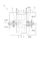
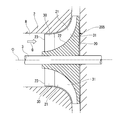
- FIG. 1 is a schematic configuration diagram of a compressor in the first embodiment of the present invention.
- the compressor 1 includes a casing 2, a rotating shaft 3, a bearing portion 4, and an impeller 5.
- a centrifugal compressor is illustrated as the compressor 1, but an axial flow compressor may be used.
- the casing 2 accommodates the rotating shaft 3, the bearing portion 4, and the impeller 5 therein.
- the casing 2 forms a flow path (not shown) through which the fluid to be compressed flows together with the impeller 5.
- the rotary shaft 3 is supported so as to be rotatable around the axis O through a bearing portion 4.
- a rotating power source (not shown) such as a motor is linked to the rotating shaft 3. That is, the rotary shaft 3 can be rotated by driving the rotational power source.
- the bearing unit 4 includes a journal bearing 41 and a thrust bearing 42.
- the bearing portion 4 of the first embodiment includes two journal bearings 41 and one thrust bearing 42, respectively.
- the journal bearing 41 supports a load that acts on the rotating shaft 3 in the radial direction with respect to the axis O.
- the thrust bearing 42 supports a load acting in the direction of the axis O with respect to the rotary shaft 3 via a thrust collar 3 a that protrudes radially outward from the rotary shaft 3.
- the impeller 5 is fixed to the rotary shaft 3 and rotates at a high speed together with the rotary shaft 3. Thereby, the impeller 5 compresses the fluid G that has flowed into the casing 2 from the suction port (not shown), and discharges the compressed fluid Gc from the discharge port (not shown).
- a plurality of impellers 5 in the first embodiment are provided in the direction of the axis O, and the fluid G is compressed stepwise by each impeller 5 to become a compressed fluid Gc.
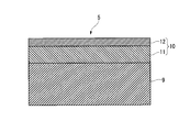
- FIG. 2 is an enlarged cross-sectional view of the surface of the impeller 5 in the first embodiment of the present invention.
- the impeller 5 has a coating layer 10 on the surface of the base material 9.
- the base material 9 is made of stainless steel, for example.
- the coating layer 10 ensures the corrosion resistance and wear resistance of the base material 9.
- the coating layer 10 includes a corrosion resistant layer 11 and an abrasion resistant layer 12.
- the corrosion-resistant layer 11 is formed in layers so as to cover the surface of the base material 9.
- the corrosion resistant layer 11 is formed of a nickel base alloy or a cobalt base alloy, more specifically, a nickel base alloy having a chromium content of 20 wt% or more, or a cobalt base alloy having a chromium content of 20 wt% or more.
- the corrosion-resistant layer 11 can be formed, for example, by spraying nickel base alloy and cobalt base alloy powder onto the surface of the base material 9 by thermal spraying.
- nickel-based alloys examples include Ni-20Cr, Ni-50Cr, Hastelloy X (registered trademark: Ni-22Cr-1.5Co-9Mo-0.6W-18.5Fe), and Inconel 625 (registered trademark). : Ni-21.5Cr-9Mo-3.6Nb-0.2Al-0.2Ti-2.5Fe) or the like.
- cobalt-based alloy examples include Haynes alloy 188 (registered trademark: Co-22Cr-14W-3Fe), CoNiCrAlY (Co-32Ni-21Cr-8Al-0.5Y), and CoCrAlY (Co-29Cr-6Al--). 0.8Y) or the like can be used.
- the thickness of the corrosion resistant layer 11 is, for example, about 20 ⁇ m to 1 mm.
- various thermal spraying methods such as low-pressure plasma spraying, plasma spraying in atmospheric pressure, and ultrahigh-speed spraying can be employed.
- the wear-resistant layer 12 is formed by subjecting the surface of the corrosion-resistant layer 11 to chromium diffusion penetration treatment.
- This chromium diffusion and penetration treatment is a treatment that diffuses and penetrates chromium having excellent wear resistance.
- a hard layer having a sufficiently higher chromium concentration than the corrosion-resistant layer 11 is formed on the surface of the coating layer 10 by performing chromium diffusion and penetration treatment on the surface of the corrosion-resistant layer 11.
- the wear resistant layer 12 formed by the chromium diffusion and penetration treatment has a chromium concentration that decreases as it is farther from the surface, in other words, closer to the base material 9.
- the surface chromium concentration in the first embodiment is almost 100%, and the hardness on the surface is about HV800 or more.
- the wear-resistant layer 12 may be cracked or cracked due to solid collision.
- the chromium concentration is 50 wt% or less (for example, 20 wt%), the hardness is about HV300, and the ductility and sufficient fatigue strength are secured. It doesn't happen first.
- the material to be permeated is accommodated in a steel furnace together with a preparation containing, for example, chromium powder, aluminum oxide powder, and ammonium chloride powder and sealed. Thereafter, for example, heating is performed in a furnace at 900 ° C. to 1100 ° C. for about 10 hours while passing hydrogen gas or argon gas. Then, the reaction shown by the following reaction formula occurs.
- chromium (Cr) reacts with hydrochloric acid (HCl) to become chromium chloride (CrCl 2 ; vapor).
- This chromium chloride is reduced by hydrogen (H2) on the surface of the treated metal, and chromium (Cr) is deposited.
- This deposited chromium (Cr) diffuses and permeates the treated metal surface by a diffusion reaction or a substitution reaction.
- the wear-resistant layer 12 having a thickness of about 5 to 100 ⁇ m can be formed.
- the chromium diffusion permeation treatment is not limited to the above-described diffusion permeation treatment method, as long as it can diffuse and permeate chromium into the treated metal.
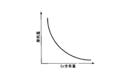
- FIG. 3 is a graph in which the vertical axis represents the wear amount and the horizontal axis represents the chromium (Cr) content.
- the higher the chromium content in other words, the higher the chromium concentration
- the amount of wear of the treated metal decreases quadratically with increasing chromium content. That is, as described above, the coating layer 10 has a higher chromium concentration as the distance from the base material 9 increases due to the chromium diffusion penetration treatment, and the wear resistance of the surface of the coating layer 10 is the highest.
- the coating layer 10 since the chromium concentration decreases as the coating layer 10 approaches the base material 9, the coating layer 10 is formed more densely as it approaches the base material 9, and pinholes and the like are not formed, and sufficient corrosion resistance is ensured near the base material 9. Is done.
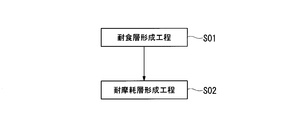
- FIG. 4 is a process flow of the coating layer manufacturing method according to the first embodiment of the present invention.
- a nickel-based alloy or cobalt-based alloy powder containing 20 wt% or more of chromium is sprayed onto the surface of the base material 9 by low-temperature plasma spraying or the like.
- a corrosion-resistant layer 11 made of a nickel-based alloy containing chromium of about 20 ⁇ m to 1 mm or a cobalt-based alloy containing chromium is formed on the surface of the base material 9 (step S01; corrosion-resistant layer forming step).
- step S02 wear-resistant layer forming step
- the wear resistant layer 12 having a high chromium concentration is formed on the surface of the corrosion resistant layer 11.
- the diffusion of atoms between the corrosion-resistant layer 11 and the base material 9 in an environment without oxidation is performed by heating the vessel to about 900 ° C. to 1100 ° C. Therefore, the adhesion between the corrosion-resistant layer 11 and the base material 9 can be increased. Therefore, the secondary effect that the corrosion-resistant layer 11 is difficult to peel from the base material 9 and the reliability of the corrosion-resistant layer 11 is improved is also produced.
- the surface of the corrosion-resistant layer 11 may be polished as a pretreatment before performing the chromium diffusion permeation treatment.
- corrugation of the surface of the corrosion-resistant layer 11 can be leveled, or an oxide film can be removed. Therefore, it is possible to diffuse and infiltrate chromium into the corrosion-resistant layer 11 more stably and with a uniform thickness.
- the chromium diffusion treatment is a process of depositing metallic chromium, can seal the pinholes originally present in the sprayed coating, and exhibits a further improvement in corrosion resistance.
- the corrosion-resistant layer 11 made of a nickel-base alloy or a cobalt-base alloy is formed on the base material 9, the base material 9 is protected from corrosion due to sulfur or the like. Can do. Furthermore, since the wear-resistant layer 12 is formed on the surface of the corrosion-resistant layer 11, it is possible to suppress wear and peeling of the corrosion-resistant layer 11 due to the collision of solid matter.
- the corrosion and wear of the base material 9 can be reduced, the reliability of the compressor 1 can be improved. Further, since the chromium diffusion and penetration treatment may be performed after forming the corrosion-resistant layer 11, the coating layer 10 having excellent corrosion resistance and wear resistance can be easily formed.
- the present invention is not limited to the above-described first embodiment, and includes various modifications made to the above-described first embodiment without departing from the spirit of the present invention. That is, the specific shape, configuration, and the like given in the first embodiment are merely examples, and can be changed as appropriate.
- the location where the coating layer 10 is formed is not limited to the surface of the impeller 5 as long as it is a location where fluid flows.
- the coating layer 10 may be formed on the inner wall of the flow path through which the fluid flows.
- the coating layer 10 is formed on the surface of a moving blade, a stationary blade or the like when the compressor 1 is an axial compressor.
- the present invention is not limited to this.
- the present invention can also be applied to a compressor including two or less impellers 5 or a compressor including four or more impellers 5 (the same applies to the second to fifth embodiments below).
- the compressor 1 in the first embodiment described above is used in a seabed production system and a floating offshore oil storage facility is illustrated.
- the present invention is not limited to the compressor used in these submarine production systems and floating offshore oil storage facilities (hereinafter, the same applies to the second to fifth embodiments).
- FIG. 5 is a circumferential sectional view of the impeller in the second embodiment of the present invention.
- the compressor according to the second embodiment of the present invention includes a casing 2, a rotating shaft 3, a bearing portion 4, and an impeller 205.
- the impeller 205 includes a disk unit 20 and a blade unit 21.
- the disk part 20 is fixed to the rotary shaft 3 by shrink fitting or the like.
- the disk portion 20 gradually expands from the inflow side (left side in FIG.
- the disk portion 20 has a concave curved surface 22 formed on the inflow side in the axis O direction.
- the curved surface 22 is formed so as to be curved so as to face the direction intersecting the axis O on the inflow side in the axial direction and gradually toward the direction of the axis O toward the side opposite to the inflow side in the direction of the axis O. ing.
- the blade part 21 is formed so as to protrude from the curved surface 22 of the disk part 20 described above. More specifically, the blade portion 21 extends in a strip shape along the curved surface 22 from the inner side to the outer side in the radial direction with respect to the axis O.
- the blade portion 21 in the second embodiment is formed so that its width dimension gradually decreases from the radially inner side to the radially outer side. A plurality of blade portions 21 formed in this way are formed at intervals in the circumferential direction.
- FIG. 6 is a perspective view of the impeller in the second embodiment of the present invention.
- the blade portion 21 is formed to be curved toward one side in the circumferential direction.
- the blade portion 21 is further formed to be inclined so that the inflow side in the direction of the axis O is disposed on the other side in the circumferential direction.
- the blade portion 21 further includes a curved portion 24 at a predetermined position from a so-called leading edge (front edge portion) 23.
- the curved portion 24 is curved so as to be convex toward one side in the circumferential direction.
- the shape of the blade portion 21 is not limited to the shape described above.
- the blade portion 21 may be formed linearly without being curved.
- the impeller 205 rotates around the axis O together with the rotary shaft 3 by having the above-described configuration. By this rotation, the impeller 205 sends out the fluid G flowing in from the inflow side in the direction of the axis O to the outside in the radial direction.
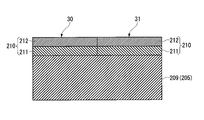
- FIG. 7 is an enlarged cross-sectional view of the blade surface in the second embodiment of the present invention.
- the impeller 205 has a coating layer 210 on the surface of its base material 209.
- the base material 209 is made of stainless steel, for example.
- the coating layer 210 ensures the corrosion resistance and wear resistance of the base material 209.
- the coating layer 210 includes a corrosion resistant layer 211 and an abrasion resistant layer 212.
- the corrosion resistant layer 211 is formed in a layer shape so as to cover the surface of the base material 209 of the impeller 205.
- the corrosion resistant layer 211 is formed of a nickel base alloy or a cobalt base alloy, more specifically, a nickel base alloy having a chromium concentration of 20 wt% or more, or a cobalt base alloy having a chromium concentration of 20 wt% or more.
- the corrosion-resistant layer 211 can be formed, for example, by spraying a nickel-based alloy and a cobalt-based alloy powder onto the surface of the base material 209 by thermal spraying.
- nickel-based alloy examples include Ni-20Cr, Ni-50Cr, Hastelloy X (registered trademark: Ni-22Cr-1.5Co-9Mo-0.6W-18.5Fe), and Inconel 625 (registered trademark: Ni -21.5Cr-9Mo-3.6Nb-0.2Al-0.2Ti-2.5Fe) or the like.
- cobalt-based alloy examples include Haynes alloy 188 (registered trademark: Co-22Cr-14W-3Fe), CoNiCrAlY (Co-32Ni-21Cr-8Al-0.5Y), and CoCrAlY (Co-29Cr-6Al--). 0.8Y) or the like can be used.
- the thickness of the corrosion resistant layer 211 is, for example, about 20 ⁇ m to 1 mm.
- various thermal spraying methods such as low-pressure plasma spraying, plasma spraying in atmospheric pressure, and ultrahigh-speed spraying can be employed.
- the wear resistant layer 212 is formed by performing a chromium diffusion penetration process on the surface of the corrosion resistant layer 211.
- This chromium diffusion and penetration treatment is a treatment that diffuses and penetrates chromium having excellent corrosion resistance.
- a hard layer having a sufficiently higher chromium concentration than the corrosion-resistant layer 211 is formed on the surface of the coating layer 210 by performing the chromium diffusion and penetration treatment on the surface of the corrosion-resistant layer 211.
- the wear resistant layer 212 formed by the chromium diffusion and penetration treatment has a chromium content that decreases as it is farther from the surface, in other words, closer to the base material 209.
- the chromium concentration on the surface in the second embodiment is almost 100%, and the hardness on the surface is about HV800 or more.
- the chromium concentration is higher than 50 wt%, it becomes excessively hard and the ductility is lost, and the fatigue strength is lowered. Therefore, the wear resistant layer 212 may be cracked or cracked due to the collision of solid matter.
- the chromium concentration is 50 wt% or less (for example, 20 wt%)
- the hardness is about HV300, and the ductility and sufficient fatigue strength are ensured. It doesn't happen first.
- the material to be permeated is accommodated in a steel furnace together with a preparation containing, for example, chromium powder, aluminum oxide powder, and ammonium chloride powder and sealed. Thereafter, for example, heating is performed in a furnace at 900 ° C. to 1100 ° C. for about 10 hours while passing hydrogen gas or argon gas. Then, the reaction shown by the following reaction formula occurs.
- chromium (Cr) reacts with hydrochloric acid (HCl) to become chromium chloride (CrCl 2 ; vapor).
- This chromium chloride is reduced by hydrogen (H2) on the surface of the treated metal, and chromium (Cr) is deposited.
- This deposited chromium (Cr) diffuses and permeates the treated metal surface by a diffusion reaction or a substitution reaction.
- the wear-resistant layer 12 having a thickness of about 5 to 100 ⁇ m can be formed.
- the chromium diffusion permeation treatment is not limited to the above-described diffusion permeation treatment method, as long as it can diffuse and permeate chromium into the treated metal.
- the higher the chromium content in other words, the higher the chromium concentration
- the lower the wear amount of the treated metal the higher the chromium content
- the amount of wear of the treated metal decreases quadratically with increasing chromium content.
- the coating layer 210 can be made higher as the chromium concentration is further away from the base material 209 by the chromium diffusion and penetration treatment, and the wear resistance of the surface of the coating layer 210 can be maximized.
- the coating layer 210 that has been subjected to the chromium diffusion permeation treatment has a chromium concentration that decreases as it approaches the base material 209. Therefore, the closer to the base material 209, the closer the base material 209 is formed, and no pinholes are formed, and sufficient corrosion resistance is ensured in the vicinity of the base material 209.
- the coating layer 210 described above has a chromium concentration on the surface of the first region 30 including at least the leading edge (front edge) 23 of the blade portion 21. It is formed to be higher than the chromium concentration on the surface of the two regions 31.
- the left side of the broken line of the blade portion 21 is the first region 30, and the right side is the second region 31.
- the leading edge 23 is a portion where the fluid G flowing into the compressor 1 collides at the highest speed.
- the fluid G swirls toward the outer peripheral side of the blade portion 21, so that the collision speed of the fluid G is greatly reduced. That is, the first region 30 is set so as to include a region that is most easily worn out of the surface of the blade portion 21.
- the hardness of the first region 30 is relatively high due to the high chromium concentration (for example, about HV1000), if the region is too wide, handling at the time of manufacturing becomes difficult. If the hardness of the first region 30 is high, the ductility may decrease and the fatigue strength may decrease.
- the first region 30 is 50% of the length dimension (hereinafter simply referred to as the axial dimension) of the blade part 21 in the axis O direction from the leading edge 23 in the axis O direction on the surface of the blade part 21.
- the axial dimension 50% of the length dimension (hereinafter simply referred to as the axial dimension) of the blade part 21 in the axis O direction from the leading edge 23 in the axis O direction on the surface of the blade part 21.
- the first region 30 may be a region that is 25% of the axial dimension from the leading edge 23. By doing in this way, the fatigue strength is further reduced as compared with the case where the axial dimension from the leading edge 23 of the first region 30 is 50% while suppressing the wear at the leading edge 23 and its vicinity. The handling at the time of manufacture can be improved.
- the first region 30 may be a region that is 10% of the axial dimension from the leading edge 23.
- the fatigue strength is further reduced as compared with the case where the axial dimension from the leading edge 23 of the first region 30 is 50% or 25%, particularly while suppressing wear at the leading edge 23.
- the handling at the time of manufacture can be improved.
- the first region 30 is narrower than the region of 10% of the axial dimension from the leading edge 23, skill is required to accurately apply the wear-resistant layer 12 to the leading edge 23. There is a possibility that the burden on the project will increase.
- the first area 30 is not limited to the above-described areas of 50%, 25%, and 10%.
- the region 30 may be used. By doing in this way, especially the area
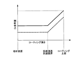
- FIG. 8 is a graph in which the vertical axis represents the chromium (Cr) content and the horizontal axis represents the depth of the coating layer.
- the chromium content (in other words, chromium concentration) of the first region 30 in the second embodiment is shown by a solid line
- the chromium content (in other words, chromium concentration) of the second region 31 is shown by a broken line.
- the corrosion resistance layer 211 formed on the surface of the base material 209 has different chromium concentrations in the first region 30 and the second region 31. More specifically, in the corrosion-resistant layer 11, the chromium concentration in the first region 30 is higher than the chromium concentration in the second region 31.
- the chromium concentration of the corrosion-resistant layer 11 of the second embodiment is in the range of 20 wt% to 50 wt% in both the first region 30 and the second region 31, and the first region 30 and the second region are within this range. Each chromium concentration is different from that of the region 31.
- the coating layer 210 in the second embodiment is a wear-resistant layer by performing the same chromium diffusion penetration treatment on both the first region 30 and the second region 31 of the corrosion-resistant layer 211 having different chromium concentrations. 212 is formed. According to this chromium diffusion and penetration treatment, chromium diffuses and penetrates evenly on the surfaces of the corrosion-resistant layers 211 in both the first region 30 and the second region 31. As a result, the wear resistant layer 212 having a higher chromium concentration than the corrosion resistant layer 211 is formed on both surfaces of the first region 30 and the second region 31.
- chromium diffuses and penetrates evenly on the surface of the corrosion-resistant layer 211 in both the first region 30 and the second region 31, so that the surface of the wear-resistant layer 212 in the first region 30 is more
- the chromium concentration is higher than the surface of the wear-resistant layer 212, and wear resistance is increased.
- the chromium concentration of each wear-resistant layer 212 in the first region 30 and the second region 31 gradually decreases from the surface of the coating layer 210 toward the diffusion penetration reach limit.
- the diffusion penetration reach limit is a limit of the depth at which chromium can reach from the surface of the coating layer 210 by the chromium diffusion penetration treatment.
- FIG. 9 is a process flow of the impeller manufacturing method according to the second embodiment of the present invention.
- FIG. 10 is an enlarged cross-sectional view showing a state in which a corrosion-resistant layer is formed on the base material of the blade portion in the second embodiment of the present invention.
- step S201 nickel base alloy or cobalt base alloy powder is sprayed onto the surface of the base material 209 of the blade portion 21 by low pressure plasma spraying or the like (step S201; corrosion resistant layer forming step). More specifically, a nickel-based alloy powder containing chromium or a cobalt-based alloy powder containing chromium is sprayed onto the first region 30 of the base material 209 by low-pressure plasma spraying or the like. Similarly, a nickel-based alloy powder containing chromium or a cobalt-based alloy powder containing chromium is sprayed onto the second region 31 of the base material 209 by low-pressure plasma spraying or the like. At this time, the chromium concentration in the first region 30 is set to be higher than the chromium concentration in the second region 31.
- the nickel-based alloy or cobalt-based alloy powder sprayed on the first region 30 contains 50 wt% chromium.
- the nickel-base alloy or cobalt-base alloy powder sprayed on the second region 31 contains 20 wt% chromium.
- both the first region 30 and the second region 31 contain a nickel-based alloy containing chromium of about 20 ⁇ m to 1 mm on the surface of the base material 209 or chromium.
- a corrosion-resistant layer 211 made of a cobalt-based alloy is formed.
- Step S202 wear-resistant layer forming step.
- a wear resistant layer 212 having a predetermined thickness and a relatively higher chromium concentration than the corrosion resistant layer 211 is formed on the entire surface of the corrosion resistant layer 211.
- the chromium concentration increases by about 50 wt% in both the first region 30 and the second region 31.
- the diffusion of atoms between the corrosion-resistant layer 211 and the base material 209 is performed in an environment without oxidation by performing the treatment while heating at about 900 ° C. to 1100 ° C. in the container. Therefore, the adhesion between the corrosion-resistant layer 211 and the base material 209 can be increased. Therefore, the secondary effect that the corrosion-resistant layer 211 is difficult to peel from the base material 209 and the reliability of the corrosion-resistant layer 211 is improved is also produced.
- the surface of the corrosion-resistant layer 211 may be polished as a pretreatment before the chromium diffusion and penetration treatment.
- corrugation of the surface of the corrosion-resistant layer 211 can be leveled, or an oxide film can be removed. Therefore, it is possible to diffuse and infiltrate chromium into the corrosion-resistant layer 211 in a more stable and uniform thickness.
- the chromium diffusion treatment is a process of depositing metallic chromium, can seal the pinholes originally present in the sprayed coating, and exhibits a further improvement in corrosion resistance.
- the corrosion-resistant layer 211 made of a nickel-based alloy or a cobalt-based alloy is formed on the base material 209 of the impeller 205, the base material 209 is corroded by sulfur or the like. Can be protected from. Further, in the impeller 205, the surface hardness of the first region 30 including the leading edge 23 of the blade portion 21, which has a high flow velocity and is likely to be worn due to particle collision, is relatively higher than the surface hardness of the second region 31. Can be increased. As a result, it is possible to sufficiently secure both corrosion resistance and wear resistance when handling a corrosive fluid containing solid matter. Moreover, since the fall of the fatigue strength by giving the hard surface treatment to the whole impeller 205 can be suppressed, the fall of reliability and manufacturability can be suppressed.
- the corrosion-resistant layer 211 in the first region 30 is formed so as to have a higher chromium concentration than the corrosion-resistant layer 211 in the second region 31, and further, the first region 30 is subjected to chromium diffusion and penetration treatment.
- the wear resistant layer 212 is formed on both the second region 31 and the second region 31. Therefore, the chromium concentration on the surface of the first region 30 can be made higher than the chromium concentration on the surface of the second region 31 while forming the wear resistant layer 212 in both the first region 30 and the second region 31. . Therefore, the hardness of the surface of the first region 30 can be relatively higher than the hardness of the surface of the second region 31.
- FIG. 11 is an enlarged cross-sectional view corresponding to FIG. 7 in a modification of the second embodiment of the present invention.
- the impeller 205a has a coating layer 210a on the surface of its base material 209.
- the coating layer 210a includes a corrosion resistant layer 211a and an abrasion resistant layer 212a.
- the corrosion-resistant layer 211a is formed in a layer shape so as to cover the surface of the base material 209 of the impeller 205.
- This corrosion-resistant layer 211a is a nickel-based alloy or a cobalt-based alloy, more specifically, a nickel-based alloy having a chromium concentration of 20 wt% or more, or a chromium concentration of 20 wt%, as in the second embodiment described above. It is formed of the above cobalt base alloy.
- the chromium concentration of the corrosion resistant layer 211a is, for example, in the range of 20 wt% to 50 wt%.
- the wear resistant layer 212a is formed by performing chromium diffusion and penetration treatment on the first region 30 including the leading edge 23 in the surface of the corrosion resistant layer 211a.
- the wear resistant layer 212 a is not formed in the second region 31 other than the first region 30. That is, a hard layer having a sufficiently higher chromium concentration than the corrosion-resistant layer 211a is formed on the surface of the first region 30 among the surfaces of the coating layer 210a.
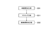
- FIG. 12 is a process flow of an impeller manufacturing method according to a modification of the second embodiment of the present invention.
- a nickel-base alloy powder or a cobalt-base alloy powder is sprayed onto the surface of the base material 209 of the blade portion 21 by low-pressure plasma spraying or the like (step S201; corrosion-resistant layer forming step).
- a nickel-based alloy powder containing chromium or a cobalt-based alloy powder containing chromium is applied to both the first region 30 and the second region 31 of the base material 209 using low-pressure plasma. Spray by spraying.
- the nickel base alloy or cobalt base alloy sprayed on the first region 30 is the same as the nickel base alloy or cobalt base alloy sprayed on the second region 31. That is, the corrosion-resistant layer 211a having a constant chromium concentration is uniformly formed on the surface of the base material 209.
- the nickel-base alloy powder or the cobalt-base alloy powder sprayed on the first region 30 and the second region 31 contains, for example, 20 wt% chromium.
- step S211 masking step.
- This masking process only needs to inhibit the penetration of chromium chloride gas into the second region 31 by the chromium diffusion penetration process.
- metal masking can be illustrated as a masking process.
- a method of exposing only the first region 30 and covering the second region 31 with a metal box (not shown) can be exemplified.
- a powdery or slurry-like masking material (for example, manufactured by APV) or the like is attached to the second region 31 to cover it.
- the masking material can be adhered to the surface of the second region 31 by adding a binder.
- step S202 wear-resistant layer forming step.
- the corrosion-resistant layer 11 in the second region 31 has been subjected to masking treatment, only the first region 30 is subjected to chromium diffusion and penetration treatment.
- a wear-resistant layer 212a having a predetermined thickness and a high chromium concentration is formed on the surface of the first region 30 among the surfaces of the corrosion-resistant layer 211a.
- the chromium concentration of the surface of the wear-resistant layer 212a in the first region 30 rises to about 100 wt%
- the surface of the corrosion-resistant layer 211a in the second region 31 has a chromium concentration of about 20 wt%.
- the same nickel base alloy or cobalt base alloy may be laminated on the base material 209 in both the first region 30 and the second region 31, and therefore the corrosion resistant layer 211a. Can be easily formed. Furthermore, since the chromium diffusion permeation process is performed only on the surface of the first region 30, the difference between the chromium concentration of the first region 30 and the chromium concentration of the surface of the second region 31 can be further increased. In other words, only the hardness of the surface of the first region 30 can be increased without increasing the hardness of the surface of the second region 31. Therefore, it is possible to sufficiently suppress a decrease in fatigue strength on the surface of the second region 31 while improving the wear resistance of the first region 30 where solids are likely to collide at high speed.
- the chromium diffusion permeation treatment can be easily and stably performed on the surface of the corrosion-resistant layer 211 a in the first region 30 by masking the second region 31 while leaving the first region 30. Further, the diffusion and penetration of chromium into the second region 31 can be effectively suppressed.
- the surface of the corrosion-resistant layer 211a may be polished.
- the present invention is not limited to the above-described second embodiment and its modifications, and includes various modifications made to the above-described second embodiment without departing from the spirit of the present invention. . That is, the specific shape, configuration, and the like given in the second embodiment are merely examples, and can be changed as appropriate.
- the chromium diffusion and permeation process is performed after the masking process has been described.
- the chromium concentration on the surface of the first region 30 is relatively higher than the surface of the second region 31.
- the first region 30 is focused on the diffusion of chromium. You may make it process.
- the compressor according to the second embodiment described above includes a so-called open type impeller 205
- the impeller 205 is not limited to the open type.
- a closed impeller provided with a cover member may be used.
- FIG. 13 is an enlarged cross-sectional view of the impeller surface in the third embodiment of the present invention.
- the compressor according to the third embodiment includes a casing 2, a rotating shaft 3, a bearing portion 4, and an impeller 305.
- the impeller 305 includes a disk unit 20 and a blade unit 21.
- the impeller 305 has a coating layer 310 on the surface of its base material 309.
- the base material 309 is made of stainless steel, for example.
- the coating layer 310 ensures the corrosion resistance and wear resistance of the base material 309.
- the coating layer 310 includes a corrosion resistant layer 311.
- the corrosion resistant layer 311 is formed in a layer shape so as to cover the surface of the base material 309 of the impeller 305.
- the corrosion-resistant layer 311 is formed in a layer form from a nickel-based alloy or a cobalt-based alloy, more specifically, a nickel-based alloy having a chromium concentration of 20 wt% or more, or a cobalt-based alloy having a chromium concentration of 20 wt% or more. ing.
- the corrosion-resistant layer 311 has a plurality of hard particles K formed of a material having a hardness higher than that of the nickel-based alloy or the cobalt-based alloy forming the corrosion-resistant layer 311 in the layer.
- the chromium concentration of the nickel-based alloy and the chromium concentration of the cobalt-based alloy are both 20 to 50 wt%.
- the chromium concentration is less than 20 wt%, it becomes easy to wear, and when the chromium concentration is more than 50 wt%, the hardness is excessively increased, pinholes and the like are formed and the corrosion resistance is lowered, and the ductility is lowered. As a result, the fatigue strength is lowered and handling becomes difficult.
- nickel-based alloy examples include Ni-20Cr, Ni-50Cr, Hastelloy X (registered trademark: Ni-22Cr-1.5Co-9Mo-0.6W-18.5Fe), and Inconel 625 (registered trademark: Ni -21.5Cr-9Mo-3.6Nb-0.2Al-0.2Ti-2.5Fe) or the like.
- cobalt-based alloy examples include Haynes alloy 188 (registered trademark: Co-22Cr-14W-3Fe), CoNiCrAlY (Co-32Ni-21Cr-8Al-0.5Y), and CoCrAlY (Co-29Cr-6Al--). 0.8Y) or the like can be used.
- the thickness of the corrosion resistant layer 311 is, for example, about 20 ⁇ m to 1 mm.
- the hardness of the nickel base alloy and the cobalt base alloy is about HV300 in terms of Vickers hardness. That is, the nickel-base alloy and the cobalt-base alloy in the third embodiment are each ductile and sufficiently ensure fatigue strength. Therefore, cracks, cracks, and the like due to excessively high hardness are less likely to occur.
- the hard particles K include tungsten carbide (WC), chromium carbide (Cr 3 C 2 ), silicon carbide (SiC), silicon nitride (Si 3 N 4 ), cubic boron nitride (Cbn), and oxidation.
- Aluminum (Al 2 O 3 ) or the like can be used.
- the hardness of the hard particles K is, for example, Vickers hardness, about HV2500 for tungsten carbide, and about HV1300 for chromium carbide. Furthermore, it is about HV2400 for silicon carbide, about HV1800 for silicon nitride, about HV5000 for cubic boron nitride, and about HV2200 for aluminum oxide.
- the hard particles K are formed to have a particle size of 5 to 50 ⁇ m.
- the particle size of the hard particles K is less than 5 ⁇ m, the resistance to wear is reduced, and the particles tend to aggregate at the time of film formation, so that an uneven structure tends to be formed.
- the particle size of the hard particles K exceeds 50 ⁇ m, it becomes difficult to disperse the hard particles K in the corrosion-resistant layer 311.
- the corrosion-resistant layer 311 contains 50 to 90 vol% hard particles K with respect to the nickel-based alloy or the cobalt-based alloy. In other words, the corrosion-resistant layer 311 contains 10 to 50 vol% nickel-base alloy or cobalt-base alloy.
- the plurality of hard particles K are arranged so as to be uniformly dispersed.
- the ratio of the hard particles K to the nickel-based alloy or the cobalt-based alloy is less than 50 vol%, the probability that the solid matter contained in the fluid G collides with the hard particles K is reduced, and the corrosion-resistant layer 311 is worn. It cannot be reduced sufficiently.
- the ratio of the hard particles K to the nickel-base alloy or cobalt-base alloy exceeds 90 vol%, most of the corrosion-resistant layer 311 becomes the hard particles K, so that the density of the corrosion-resistant layer 311 is excessively lowered and corrosion occurs. Insufficient anti-corrosion performance with respect to the fluid G.
- the corrosion resistant layer 311 can be formed by thermal spraying.
- various thermal spraying methods such as low-pressure plasma spraying, plasma spraying in atmospheric pressure, and ultrahigh-speed spraying can be employed.
- the thermal spraying material used in this thermal spraying a nickel-base alloy powder or a cobalt-base alloy powder mixed with hard particles K in advance can be used. In this way, the hard particles K are mixed in the proportion (vol%) described above with respect to the nickel-based alloy powder or the cobalt-based alloy powder.
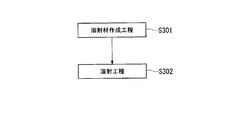
- FIG. 14 is a process flow of the coating layer manufacturing method according to the third embodiment of the present invention.
- a thermal spray material is produced (step S301; thermal spray material production process). More specifically, a nickel-based alloy powder (for example, an average particle size of about 50 ⁇ m) or a cobalt-based alloy powder (for example, an average particle size of about 50 ⁇ m) is used in addition to these nickel-based alloys and cobalt-based alloys. Also, 50 to 90 vol% (for example, 75 vol%) of hard particles K formed of a material having a high hardness are mixed.
- the created thermal spray material is sprayed onto the surface of the base material 309 (step S302; thermal spraying process).
- the thermal spraying method for example, various thermal spraying methods such as low-pressure plasma spraying, plasma spraying in atmospheric pressure, and ultrahigh-speed spraying can be adopted.
- a corrosion resistant layer 311 having a thickness of about 20 ⁇ m to 1 mm is formed so as to cover the surface of the base material 309. Thereby, the corrosion-resistant layer 311 in which the hard particles K are uniformly dispersed in the layer is formed.
- the third embodiment described above it is possible to prevent the corrosive fluid G from coming into contact with the base material 309 due to the corrosion resistance of the nickel-based alloy or the cobalt-based alloy. Further, since the hard particles K are included in the layer of the corrosion-resistant layer 311, the solid particles S included in the corrosive fluid G are repelled by the hard particles K of the corrosion-resistant layer 311 when colliding with the surface of the corrosion-resistant layer 311. . Moreover, the hardness of the corrosion-resistant layer 311 itself can be increased by including the hard particles K in the layer. Therefore, wear of the corrosion-resistant layer 311 due to collision of the solid S contained in the fluid G can be suppressed. As a result, it is possible to sufficiently ensure both the corrosion resistance and the wear resistance when handling the corrosive fluid G containing the solid S.
- the corrosion-resistant layer 311 contains 50 to 90 vol% of hard particles K
- the corrosion-resistant layer is formed by the collision of the solid S contained in the fluid G while ensuring the corrosion resistance of the nickel-based alloy or the cobalt-based alloy.
- the wear of 311 can be more effectively suppressed.
- the hard particles K are formed of at least one of tungsten carbide, chromium carbide, alumina, silicon nitride, silicon carbide, and cubic boron nitride, the hardness of the hard particles K is set to a nickel-based alloy. The wear of the corrosion-resistant layer 311 caused by the collision of the solid S contained in the fluid G, which is higher than that of the cobalt-based alloy, can be more effectively suppressed.
- the corrosion resistant layer 311 can be formed simply by mixing the nickel-based alloy powder or the cobalt-based alloy powder with the hard particles K to create a thermal spray material and spraying the thermal spray material on the base material 309. . Therefore, the corrosion resistant layer 311 having excellent corrosion resistance and wear resistance can be easily formed.
- the corrosion and wear of the portion in contact with the fluid G can be suppressed. Therefore, the reliability can be improved.
- the present invention is not limited to the above-described third embodiment, and includes various modifications made to the above-described third embodiment without departing from the spirit of the present invention. That is, the specific shapes, configurations, and the like given in the embodiment are merely examples, and can be changed as appropriate.
- the hard particles K use a single particle among tungsten carbide, chromium carbide, alumina, and cubic boron nitride is exemplified.
- the hard particles K are a combination of multiple types of particles of tungsten carbide, chromium carbide, alumina, silicon nitride, silicon carbide, and cubic boron nitride, and synergistic characteristics of each hard particle. Further corrosion resistance due to the effect can be expected.
- the corrosion-resistant layer 311 is directly formed on the surface of the base material 309 is exemplified.
- the corrosion-resistant layer 311 only needs to be formed in the outermost layer.
- another layer may be provided between the corrosion-resistant layer 311 and the base material 309.
- FIG. 15 is an enlarged cross-sectional view of the surface of the impeller in the fourth embodiment of the present invention.
- the compressor according to the fourth embodiment includes a casing 2, a rotating shaft 3, a bearing portion 4, and an impeller 405.
- the impeller 405 includes a disk unit 20 and a blade unit 21.
- the impeller 405 has a coating layer 410 on the surface of its base material 409.
- the base material 409 is made of stainless steel, for example.
- the coating layer 410 ensures the corrosion resistance and wear resistance of the base material 409.
- the coating layer 410 includes a corrosion-resistant layer 411 and an abrasion-resistant layer 412.
- the corrosion resistant layer 411 is formed in a layer shape so as to cover the surface of the base material 409.
- the corrosion resistant layer 411 is formed of a nickel-aluminum alloy.
- the corrosion resistant layer 411 can be formed by, for example, plasma spraying or wire spraying. In the case of plasma spraying, the corrosion-resistant layer 411 can be formed by spraying a mixture of nickel oxide powder and aluminum powder onto the surface of the base material 409 by spraying.
- This nickel-aluminum alloy contains 1 to 10 wt% of aluminum. In other words, the nickel-aluminum alloy contains 90 to 99 wt% nickel.
- nickel-aluminum alloy layer is formed by thermal spraying on the surface of the base material 409, the temperature becomes high due to the thermite reaction, so that a very dense layer can be formed.
- This nickel-aluminum alloy is very soft and highly ductile.
- the adhesion with the base material becomes extremely high. That is, it is possible to follow the deformation of the base material 409 without causing cracks or cracks.
- the wear resistant layer 412 is formed by performing a chromium diffusion penetration process on the surface of the corrosion resistant layer 411.
- This chromium diffusion and penetration treatment is a treatment that diffuses and penetrates chromium having excellent wear resistance.
- a hard layer having a sufficiently higher chromium concentration than the corrosion-resistant layer 411 is formed on the surface of the coating layer 410.
- the wear resistant layer 412 formed by the chromium diffusion penetration process decreases in concentration of chromium as it is farther from the surface, in other words, closer to the base material 409.
- the chromium concentration on the surface in the fourth embodiment is almost 100%, and the hardness on the surface is about HV800 or more.
- the material to be permeated is accommodated in a steel furnace together with a preparation containing, for example, chromium powder, aluminum oxide powder, and ammonium chloride powder and sealed. Thereafter, for example, heating is performed in a furnace at 900 ° C. to 1100 ° C. for about 10 hours while passing hydrogen gas or argon gas. Then, the reaction shown by the following reaction formula occurs.
- chromium (Cr) reacts with hydrochloric acid (HCl) to become chromium chloride (CrCl 2 ; vapor).
- This chromium chloride is reduced by hydrogen (H2) on the surface of the treated metal, and chromium (Cr) is deposited.
- This deposited chromium (Cr) diffuses and permeates the treated metal surface by a diffusion reaction or a substitution reaction.
- a wear-resistant layer 412 having a thickness of about 5 to 100 ⁇ m can be formed.
- the chromium diffusion permeation treatment is not limited to the above-described diffusion permeation treatment method, as long as it can diffuse and permeate chromium into the treated metal.
- the higher the chromium content in other words, the higher the chromium concentration
- the lower the wear amount of the treated metal the lower the wear amount of the treated metal.
- the amount of wear of the treated metal decreases quadratically with increasing chromium content. That is, as described above, the coating layer 410 has a higher chromium concentration as the distance from the base material 409 increases due to the chromium diffusion and penetration treatment, and the wear resistance of the surface of the coating layer 410 is the highest.
- the coating layer 410 has a chromium concentration that decreases as it approaches the base material 409, so that the coating layer 410 is denser as it approaches the base material 409, and no pinholes are formed, and sufficient corrosion resistance is ensured near the base material 409. Is done.
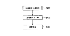
- FIG. 16 is a process flow of the coating layer manufacturing method according to the fourth embodiment of the present invention.
- nickel oxide for example, 95 wt%
- aluminum for example, 5 wt%
- a corrosion-resistant layer 411 made of a nickel-aluminum alloy with a thickness of about 20 ⁇ m to 1 mm is formed on the surface of the base material 409 (step S401; corrosion-resistant layer forming step).
- step S402 wear-resistant layer forming step, chromium diffusion and penetration treatment step.
- step S402 wear-resistant layer forming step, chromium diffusion and penetration treatment step.
- a wear resistant layer 412 having a high chromium concentration is formed on the surface of the corrosion resistant layer 411.
- the diffusion of atoms between the corrosion-resistant layer 411 and the base material 409 is performed in an environment without oxidation by performing the treatment while heating at about 900 ° C. to 1100 ° C. in the container. Therefore, the adhesion between the corrosion-resistant layer 411 and the base material 409 can be increased. Therefore, the secondary effect that the corrosion resistant layer 411 hardly peels from the base material 409 and the reliability of the corrosion resistant layer 411 is improved also occurs.
- the surface of the corrosion-resistant layer 411 may be polished as a pretreatment before the chromium diffusion and penetration treatment.
- corrugation of the surface of the corrosion-resistant layer 411 can be leveled, or an oxide film can be removed. Therefore, chromium can be diffused and penetrated into the corrosion-resistant layer 411 more stably and with a uniform thickness.
- the chromium diffusion treatment is a process of depositing metallic chromium, can seal the pinholes originally present in the sprayed coating, and exhibits a further improvement in corrosion resistance.
- the nickel-aluminum alloy corrosion-resistant layer 411 having a high density and high ductility can be formed on the surface of the base material 409. Further, since the wear-resistant layer 412 is formed so as to cover the corrosion-resistant layer 411, wear of the corrosion-resistant layer 411 due to collision of solid substances contained in the fluid G can be suppressed. In addition, since the ductility of the corrosion-resistant layer 411 is high, the stress acting on the corrosion-resistant layer 411 can be relieved by causing the corrosion-resistant layer 411 to absorb the deformation of the base material 409.
- the wear resistant layer 412 has a high hardness, it is possible to suppress the occurrence of damage such as cracks, cracks, and peeling in the wear resistant layer 412. As a result, it is possible to sufficiently ensure both corrosion resistance and wear resistance when handling the corrosive fluid G containing solid matter.
- a hard chromium layer having a high chromium concentration can be formed as the wear-resistant layer 412 on the surface of the corrosion-resistant layer 411 provided with a nickel-aluminum alloy in layers by the chromium diffusion and penetration treatment. Therefore, it is possible to sufficiently maintain the corrosion resistance of the corrosion-resistant layer 411 while suppressing the corrosion-resistant layer 411 from being worn by the collision of the solid matter contained in the fluid G and the base material 409 from being worn.
- the reliability at the time of handling the corrosive fluid G containing a solid substance can be improved by applying the coating layer 410 mentioned above to a compressor. Furthermore, since the wear resistant layer 412 can be formed only by performing chromium diffusion and penetration treatment on the surface of the corrosion resistant layer 411, the coating layer 410 having both corrosion resistance and wear resistance can be easily formed.
- the hardness of the surface of the nickel-aluminum alloy can be increased by increasing the chromium concentration on the surface of the nickel-aluminum alloy.
- FIG. 17 is an enlarged cross-sectional view corresponding to FIG. 15 in the fifth embodiment of the present invention.
- the impeller 405a has a coating layer 410a on the surface of its base material 409.
- the base material 409 is made of stainless steel, for example.
- the coating layer 410a ensures the corrosion resistance and wear resistance of the base material 409.
- the coating layer 410a includes a corrosion resistant layer 411 and an abrasion resistant layer 412a.
- the corrosion resistant layer 411 is formed in a layer shape so as to cover the surface of the base material 409 of the impeller 405a.
- the corrosion-resistant layer 411 is formed in a layer form from a nickel-based alloy or a cobalt-based alloy, more specifically, a nickel-based alloy having a chromium concentration of 20 wt% or more, or a cobalt-based alloy having a chromium concentration of 20 wt% or more. ing.
- the chromium concentration of the nickel-based alloy and the chromium concentration of the cobalt-based alloy are both 20 to 50 wt%.
- the chromium concentration is less than 20 wt%, it becomes easy to wear, and when the chromium concentration is more than 50 wt%, the hardness is excessively increased, pinholes and the like are formed and the corrosion resistance is lowered, and the ductility is lowered. As a result, the fatigue strength is lowered and handling becomes difficult.
- nickel-based alloy examples include Ni-20Cr, Ni-50Cr, Hastelloy X (registered trademark: Ni-22Cr-1.5Co-9Mo-0.6W-18.5Fe), and Inconel 625 (registered trademark: Ni -21.5Cr-9Mo-3.6Nb-0.2Al-0.2Ti-2.5Fe) or the like.
- cobalt-based alloy examples include Haynes alloy 188 (registered trademark: Co-22Cr-14W-3Fe), CoNiCrAlY (Co-32Ni-21Cr-8Al-0.5Y), and CoCrAlY (Co-29Cr-6Al--). 0.8Y) or the like can be used.
- the thickness of the corrosion resistant layer 411 is, for example, about 20 ⁇ m to 1 mm.
- various thermal spraying methods such as low-pressure plasma spraying, plasma spraying in atmospheric pressure, and ultrahigh-speed spraying can be employed.
- the hard particles K include tungsten carbide (WC), chromium carbide (Cr 3 C 2 ), silicon carbide (SiC), silicon nitride (Si 3 N 4 ), cubic boron nitride (Cbn), and oxidation.
- Aluminum (Al 2 O 3 ) or the like can be used.
- the hardness of the hard particles K is, for example, Vickers hardness, about HV2500 for tungsten carbide, and about HV1300 for chromium carbide. Furthermore, it is about HV2400 for silicon carbide, about HV1800 for silicon nitride, about HV5000 for cubic boron nitride, and about HV2200 for aluminum oxide.
- the hard particles K are formed to have a particle size of 5 to 50 ⁇ m.
- the particle size of the hard particles K is less than 5 ⁇ m, the resistance to wear is reduced, and the particles tend to aggregate at the time of film formation, so that a non-uniform structure tends to be formed.
- the particle diameter of the hard particles K exceeds 50 ⁇ m, it is difficult to disperse the hard particles K in the corrosion-resistant layer 411.
- the wear-resistant layer 412a contains 50 to 90 vol% of hard particles K with respect to the nickel-based alloy or the cobalt-based alloy. In other words, the wear-resistant layer 412a contains 10 to 50 vol% nickel-base alloy or cobalt-base alloy.
- the plurality of hard particles K are arranged so as to be uniformly dispersed.
- the ratio of the hard particles K to the nickel-based alloy or the cobalt-based alloy is less than 50 vol%, the probability that the solid matter contained in the fluid G will collide with the hard particles K decreases, and the wear of the wear-resistant layer 412a is reduced. Cannot be reduced sufficiently.
- the abrasion resistant layer 412a can be formed by thermal spraying.
- various thermal spraying methods such as low-pressure plasma spraying, plasma spraying in atmospheric pressure, and ultrahigh-speed spraying can be employed.
- the thermal spraying material used in this thermal spraying a nickel-base alloy powder or a cobalt-base alloy powder mixed with hard particles K in advance can be used. In this way, the hard particles K are mixed in the proportion (vol%) described above with respect to the nickel-based alloy powder or the cobalt-based alloy powder.
- FIG. 18 is a process flow of the coating layer manufacturing method according to the fifth embodiment of the present invention.
- the corrosion-resistant layer forming step step S401
- a wear resistant layer forming step step S402
- a thermal spray material is created (step S403; thermal spray material creating step).
- a nickel-based alloy powder for example, an average particle size of about 50 ⁇ m
- a cobalt-based alloy powder for example, an average particle size of about 50 ⁇ m
- 50 to 90 vol% for example, 75 vol%
- hard particles K formed of a material having a high hardness are mixed.
- the created thermal spray material is sprayed on the surface of the base material 409 (step S404; thermal spraying process).
- the thermal spraying method for example, various thermal spraying methods such as low-pressure plasma spraying, plasma spraying in atmospheric pressure, and ultrahigh-speed spraying can be adopted.
- a wear resistant layer 412a of about 20 ⁇ m to 1 mm, for example, is formed so as to cover the surface of the base material 409.
- the wear-resistant layer 412a in which the hard particles K are uniformly dispersed in the layer is formed.
- the hard particles K are contained in the nickel-based alloy or the cobalt-based alloy layer of the wear-resistant layer 412a, so that the solid matter S contained in the corrosive fluid G is resistant to damage.
- the hard particles K of the wear-resistant layer 412a By including the hard particles K in the layer in this way, the hardness of the wear resistant layer 412a itself can be increased. Therefore, wear of the corrosion-resistant layer 411 due to collision of the solid S contained in the fluid G can be suppressed. As a result, it is possible to sufficiently ensure both the corrosion resistance and the wear resistance when handling the corrosive fluid G containing the solid S.
- the wear-resistant layer 412a contains 50 to 90 vol% of hard particles K, the corrosion resistance due to collision of the solid S contained in the fluid G is ensured while ensuring the corrosion resistance of the nickel-base alloy or the cobalt-base alloy. Wear of the wear layer 412a can be more effectively suppressed.
- the hard particles K are formed of at least one of tungsten carbide, chromium carbide, alumina, silicon nitride, silicon carbide, and cubic boron nitride, the hardness of the hard particles K is set to a nickel-based alloy. Further, the wear of the wear-resistant layer 412a due to the collision of the solid S contained in the fluid G which is higher than that of the cobalt-based alloy can be more effectively suppressed.
- a hard coating K is prepared by mixing nickel-based alloy powder or cobalt-based alloy powder with hard particles K, and the wear-resistant layer 412a can be formed simply by spraying this sprayed material on the base material 409. it can. Therefore, the wear resistant layer 412a having excellent corrosion resistance and wear resistance can be easily formed.
- the present invention is not limited to the above-described fourth and fifth embodiments, and includes those in which various modifications are made to the above-described fourth and fifth embodiments without departing from the spirit of the present invention. . That is, the specific shapes, configurations, and the like given in the fourth and fifth embodiments are merely examples, and can be changed as appropriate.
- the coating layers 410 and 410a are formed on the surfaces of the impellers 405 and 405a.
- the locations where the coating layers 410 and 410a are formed are not limited to the surfaces of the impellers 405 and 405a as long as the fluid flows in the locations.
- the coating layers 410 and 410a may be formed on the inner wall of the flow path through which the fluid flows.
- the coating layers 410 and 410a are formed on the surfaces of the moving blades and the stationary blades when the compressor is an axial compressor.
- the hard particles K are a single particle of tungsten carbide, silicon nitride, silicon carbide, chromium carbide, alumina, and cubic boron nitride.
- the hard particles K may be used by mixing a plurality of types of particles among tungsten carbide, chromium carbide, alumina, silicon nitride, silicon carbide, and cubic boron nitride.
- the present invention can be applied to a coating layer, a compressor, a coating layer manufacturing method, an impeller, and an impeller manufacturing method, and provides both corrosion resistance and wear resistance when handling a corrosive fluid containing solid matter. It can be secured sufficiently. Furthermore, it is possible to suppress deterioration in reliability and manufacturability while sufficiently securing both corrosion resistance and wear resistance when handling a corrosive fluid containing solid matter.
Landscapes
- Chemical & Material Sciences (AREA)
- Engineering & Computer Science (AREA)
- Mechanical Engineering (AREA)
- Chemical Kinetics & Catalysis (AREA)
- Materials Engineering (AREA)
- Metallurgy (AREA)
- Organic Chemistry (AREA)
- Physics & Mathematics (AREA)
- Plasma & Fusion (AREA)
- General Engineering & Computer Science (AREA)
- Structures Of Non-Positive Displacement Pumps (AREA)
Abstract
コーティング層(10)は、母材(9)上に積層されるニッケル基合金、又は、コバルト基合金からなる耐食層(11)と、耐食層(11)の表面にクロム拡散浸透処理を施すことで形成された耐摩耗層(12)と、を備える。
Description
この発明は、コーティング層、圧縮機、コーティング層の製造方法、インペラ、インペラの製造方法に関する。
本願は、2015年3月10日に、日本に出願された特願2015-047037号、2015年3月11日に、日本に出願された特願2015-047928号、2015年3月17日に、日本に出願された特願2015-052878号、および、2015年3月20日に、日本に出願された特願2015-058035号に基づき優先権を主張し、その内容をここに援用する。
本願は、2015年3月10日に、日本に出願された特願2015-047037号、2015年3月11日に、日本に出願された特願2015-047928号、2015年3月17日に、日本に出願された特願2015-052878号、および、2015年3月20日に、日本に出願された特願2015-058035号に基づき優先権を主張し、その内容をここに援用する。
圧縮機にあっては、非特許文献1のような海底生産システム(Subsea Production System)や、非特許文献2のような浮体式海洋石油貯蔵設備(Floating Production Storage and Offloading、FPSO)に使用されるものが知られている。非特許文献1の海底生産システムに使用される圧縮機は、例えば、海底に設置されて海底から数千mの深さまで掘削した生産井から原油や天然ガス等が混在した生産流体を海上に送り出す用途で用いられる。非特許文献2の浮体式海洋石油貯蔵設備に使用される圧縮機は、船舶等の海上設備に設置される。
三菱重工技報 Vol.34 No.5 P310-P313
Turbomachinery International September/October 2014 P18-P24
一般に用いられる圧縮機の場合、取り扱う流体は精製されている場合が多い。しかし、非特許文献1や非特許文献2で用いる圧縮機の場合、その取り扱う流体は、フィルタ等により前処理がされているものの、十分に固形物の除去がなされていない場合がある。例えば、フィルタ等による前処理としては、10μm以下の固形物を98%程度分離できるものもあるが、残りの数%が残留してしまう。また、非特許文献1や非特許文献2で取り扱う流体の場合、10μmの固形物は、硬質であることが多い。
非特許文献1や非特許文献2で取り扱う流体には、硫黄などの腐食成分が含まれている。そのため、非特許文献1や非特許文献2で用いる圧縮機には、流体と接する部分に、腐食対策として溶射などの表面処理が施されている。
しかしながら、このような腐食対策の表面処理では、上述した流体に含まれる残留した固形物によって摩耗や剥離が生じてしまい、腐食の進行を抑制できなくなる場合がある。
しかしながら、このような腐食対策の表面処理では、上述した流体に含まれる残留した固形物によって摩耗や剥離が生じてしまい、腐食の進行を抑制できなくなる場合がある。
さらに、溶射による表面処理は、特に硬質の皮膜の場合には、微小なピンホールが形成されることが多く、腐食環境が非常に厳しい場合には耐食性が充分ではない場合がある。
つまり、溶射による表面処理の耐摩耗性を向上させようとすると、十分な耐腐食性を確保することができない可能性がある。
さらに、遠心圧縮機の場合、インペラ全体に硬質な表面処理を施すことにより疲労強度が低下すると、インペラの信頼性や、製造性が低下してしまうという課題がある。
更に,皮膜の密着性の観点から耐食性の高い材料を単に溶射するだけでは充分でない可能性がある。
つまり、溶射による表面処理の耐摩耗性を向上させようとすると、十分な耐腐食性を確保することができない可能性がある。
さらに、遠心圧縮機の場合、インペラ全体に硬質な表面処理を施すことにより疲労強度が低下すると、インペラの信頼性や、製造性が低下してしまうという課題がある。
更に,皮膜の密着性の観点から耐食性の高い材料を単に溶射するだけでは充分でない可能性がある。
この発明は、固形物を含む腐食性の流体を取り扱う際の耐腐食性、耐摩耗性、及び密着性の各特性を十分に確保することができるコーティング層、圧縮機、および、コーティング層の製造方法を提供することを第一の目的とする。
この発明は、固形物を含む腐食性の流体を取り扱う際の耐腐食性、および、耐摩耗性の両方を十分に確保しつつ、信頼性、および、製造性の低下を抑制することができるインペラ、圧縮機、および、インペラの製造方法を提供することを第二の目的とする。
この発明は、固形物を含む腐食性の流体を取り扱う際の耐腐食性、耐摩耗性、及び密着性の各特性を十分に確保することができるコーティング層、圧縮機、および、コーティング層の製造方法を提供することを第三の目的とする。
この発明は、固形物を含む腐食性の流体を取り扱う際の耐腐食性、および、耐摩耗性の両方を十分に確保しつつ、信頼性、および、製造性の低下を抑制することができるインペラ、圧縮機、および、インペラの製造方法を提供することを第二の目的とする。
この発明は、固形物を含む腐食性の流体を取り扱う際の耐腐食性、耐摩耗性、及び密着性の各特性を十分に確保することができるコーティング層、圧縮機、および、コーティング層の製造方法を提供することを第三の目的とする。
この発明の第一態様によれば、コーティング層は、母材上に積層されるニッケル基合金、又は、コバルト基合金からなる耐食層と、前記耐食層の表面にクロム拡散浸透処理を施すことで形成された耐摩耗層と、を備える。
このように構成することで、母材上にニッケル基合金、又は、コバルト基合金からなる耐食層が形成されるため、母材を、硫黄分などによる腐食から守ることができる。さらに、耐食層の表面に耐摩耗層が形成されることで、固形物の衝突による耐食層の摩耗や剥離を抑制できる。
その結果、固形物を含む腐食性の流体を取り扱う際の耐腐食性、および、耐摩耗性の両方を十分に確保することができる。
このように構成することで、母材上にニッケル基合金、又は、コバルト基合金からなる耐食層が形成されるため、母材を、硫黄分などによる腐食から守ることができる。さらに、耐食層の表面に耐摩耗層が形成されることで、固形物の衝突による耐食層の摩耗や剥離を抑制できる。
その結果、固形物を含む腐食性の流体を取り扱う際の耐腐食性、および、耐摩耗性の両方を十分に確保することができる。
この発明の第二態様によれば、圧縮機は、第一態様のコーティング層を備えている。
このように構成することで、固形物を含む腐食性の流体を取り扱う圧縮機の信頼性を向上できる。
このように構成することで、固形物を含む腐食性の流体を取り扱う圧縮機の信頼性を向上できる。
この発明の第三態様によれば、コーティング層の製造方法は、母材上にニッケル基合金、又は、コバルト基合金を積層する耐食層形成工程と、前記ニッケル基合金、又は、前記コバルト基合金の表面にクロム拡散浸透処理を施す耐摩耗層形成工程と、を含む。
このようにすることで、耐食性と耐摩耗性に優れたコーティング層を容易に形成することができる。
このようにすることで、耐食性と耐摩耗性に優れたコーティング層を容易に形成することができる。
この発明の第四態様によれば、インペラは、ブレードの母材上に、耐食性を有するニッケル基合金、又は、コバルト基合金からなる耐食層と、前記耐食層の少なくとも一部に対してクロム拡散浸透処理を施すことによって形成される耐摩耗層と、を有するコーティング層と、を備える。前記コーティング層は、少なくとも前記ブレードの前縁部を含む第一領域に前記耐摩耗層を備え、前記第一領域の表面のクロム濃度が、前記第一領域以外の第二領域の表面のクロム濃度よりも高くなるように形成されている。
このように構成することで、インペラ本体のうち、流速が高く、固形物の粒子の衝突による摩耗が生じやすいブレードの前縁部を含む第一領域の表面の硬度を、第二領域の表面の硬度よりも相対的に高めることができる。その結果、固形物を含む腐食性の流体を取り扱う際の耐腐食性、および、耐摩耗性の両方を十分に確保できる。また、インペラ本体の全体に硬質な表面処理を施すことによる疲労強度の低下を抑制できるため、信頼性、および、製造性の低下を抑制することができる。
このように構成することで、インペラ本体のうち、流速が高く、固形物の粒子の衝突による摩耗が生じやすいブレードの前縁部を含む第一領域の表面の硬度を、第二領域の表面の硬度よりも相対的に高めることができる。その結果、固形物を含む腐食性の流体を取り扱う際の耐腐食性、および、耐摩耗性の両方を十分に確保できる。また、インペラ本体の全体に硬質な表面処理を施すことによる疲労強度の低下を抑制できるため、信頼性、および、製造性の低下を抑制することができる。
この発明の第五態様によれば、インペラは、第四態様における第一領域の耐食層が、前記第二領域の前記耐食層よりもクロム濃度が高くなるように形成され、前記第一領域、および、第二領域の両方に前記クロム拡散浸透処理による前記耐摩耗層が形成されるようにしてもよい。
このように構成することで、第一領域と第二領域との両方に耐摩耗層を形成しつつ、第一領域の表面のクロム濃度を、第二領域の表面のクロム濃度よりも高めることができる。
そのため、第一領域の表面の硬度を、第二領域の表面の硬度よりも相対的に高くすることができる。
このように構成することで、第一領域と第二領域との両方に耐摩耗層を形成しつつ、第一領域の表面のクロム濃度を、第二領域の表面のクロム濃度よりも高めることができる。
そのため、第一領域の表面の硬度を、第二領域の表面の硬度よりも相対的に高くすることができる。
この発明の第六態様によれば、インペラは、第四態様において、前記第一領域にのみ前記耐摩耗層を備えるようにしても良い。
このように構成することで、第一領域および第二領域の両方に耐摩耗層を形成して第一領域の表面のクロム濃度を第二領域の表面のクロム濃度よりも高くする場合よりも、さらに第一領域以外の第二領域の表面のクロム濃度を抑制することができる。そのため、第二領域の疲労強度低下をより抑制できる。また、第一領域には耐摩耗層が形成されるため、高い流速で固形物が衝突し易いブレードの前縁部の耐摩耗性を向上できる。
このように構成することで、第一領域および第二領域の両方に耐摩耗層を形成して第一領域の表面のクロム濃度を第二領域の表面のクロム濃度よりも高くする場合よりも、さらに第一領域以外の第二領域の表面のクロム濃度を抑制することができる。そのため、第二領域の疲労強度低下をより抑制できる。また、第一領域には耐摩耗層が形成されるため、高い流速で固形物が衝突し易いブレードの前縁部の耐摩耗性を向上できる。
この発明の第七態様によれば、圧縮機は、第四態様から第六態様の何れかのインペラを備える。
これにより、固形物を含む腐食性の流体を扱う圧縮機における信頼性、および、製造性を向上できる。
これにより、固形物を含む腐食性の流体を扱う圧縮機における信頼性、および、製造性を向上できる。
この発明の第八態様によれば、インペラの製造方法は、ブレードの前縁部を含む第一領域、および、前記第一領域以外の第二領域に、前記第一領域のクロム濃度が第二領域のクロム濃度よりも高くなるように、ニッケル基合金、又は、コバルト基合金を積層する耐食層形成工程を含む。このインペラ製造方法は、前記第一領域、および、前記第二領域の両方にクロム拡散浸透処理を施す耐摩耗層形成工程を更に含む。
このようにすることで、クロム濃度を、第二領域の耐摩耗層よりも第一領域の耐摩耗層の方が高くなるようにすることができる。また、耐食層の全体に同一のクロム拡散浸透処理を施すだけで、第一領域の表面のクロム濃度を、第二領域の表面のクロム濃度よりも高めて、第一領域の硬度を第二位置領域の硬度よりも高めることができる。そのため、固形物が高速で衝突し易い第一領域の耐摩耗性を向上させつつ、第二領域の表面の疲労強度低下を抑制することができる。
このようにすることで、クロム濃度を、第二領域の耐摩耗層よりも第一領域の耐摩耗層の方が高くなるようにすることができる。また、耐食層の全体に同一のクロム拡散浸透処理を施すだけで、第一領域の表面のクロム濃度を、第二領域の表面のクロム濃度よりも高めて、第一領域の硬度を第二位置領域の硬度よりも高めることができる。そのため、固形物が高速で衝突し易い第一領域の耐摩耗性を向上させつつ、第二領域の表面の疲労強度低下を抑制することができる。
この発明の第九態様によれば、インペラの製造方法は、ブレードの母材上に、ニッケル基合金、又は、コバルト基合金を積層する耐食層形成工程を含む。このインペラの製造方法は、前記ブレードの前縁部を含む第一領域と、前記第一領域以外の第二領域とのうち、前記第一領域にのみクロム拡散浸透処理を施す耐摩耗層形成工程を更に含む。
このようにすることで、第一領域および第二領域ともに同じニッケル基合金、又は、コバルト基合金を母材上に積層すればよいため、耐食層を容易に形成できる。さらに、第一領域の表面にのみクロム拡散浸透処理を施すので、第一領域のクロム濃度と、第二領域の表面のクロム濃度との差をより大きくすることができる。言い換えれば、第二領域の表面の硬度を高めずに、第一領域の硬度のみを高めることができる。そのため、固形物が高速で衝突し易い第一領域の耐摩耗性を向上させつつ、第二領域の表面における疲労強度の低下を抑制することができる。
このようにすることで、第一領域および第二領域ともに同じニッケル基合金、又は、コバルト基合金を母材上に積層すればよいため、耐食層を容易に形成できる。さらに、第一領域の表面にのみクロム拡散浸透処理を施すので、第一領域のクロム濃度と、第二領域の表面のクロム濃度との差をより大きくすることができる。言い換えれば、第二領域の表面の硬度を高めずに、第一領域の硬度のみを高めることができる。そのため、固形物が高速で衝突し易い第一領域の耐摩耗性を向上させつつ、第二領域の表面における疲労強度の低下を抑制することができる。
この発明の第十態様によれば、インペラの製造方法は、第九態様において、前記第一領域を残して前記第二領域のみをマスキング処理するマスキング工程を含むようにしてもよい。
このようにすることで、容易、且つ、安定的に、クロム拡散浸透処理を第一領域に施すことができる。また、第二領域へのクロムの拡散浸透を効果的に抑制することができる。
このようにすることで、容易、且つ、安定的に、クロム拡散浸透処理を第一領域に施すことができる。また、第二領域へのクロムの拡散浸透を効果的に抑制することができる。
この発明の第十一態様によれば、コーティング層は、母材上に層状に形成されたニッケル基合金、又は、コバルト基合金からなる耐食層を備えるコーティング層である。前記耐食層は、前記耐食層を形成するニッケル基合金、又は、前記コバルト基合金よりも硬度の高い材料から形成された複数の硬質粒子を層内に有する。
このように構成することで、ニッケル基合金、又は、コバルト基合金の有する耐食性によって、母材に腐食性の流体が接触することを抑制できる。さらに耐食層の層内に硬質粒子が含まれることによって、腐食性の流体に含まれる固形物が衝突した場合、耐食層の硬質粒子にはじかれる。また、層内に硬質粒子を含むことで、耐食層自体の硬度を増加させることができる。そのため、流体に含まれる固形物の衝突による耐食層の摩耗を抑制できる。
その結果、固形物を含む腐食性の流体を取り扱う際の耐腐食性、および、耐摩耗性の両方を十分に確保することができる。
このように構成することで、ニッケル基合金、又は、コバルト基合金の有する耐食性によって、母材に腐食性の流体が接触することを抑制できる。さらに耐食層の層内に硬質粒子が含まれることによって、腐食性の流体に含まれる固形物が衝突した場合、耐食層の硬質粒子にはじかれる。また、層内に硬質粒子を含むことで、耐食層自体の硬度を増加させることができる。そのため、流体に含まれる固形物の衝突による耐食層の摩耗を抑制できる。
その結果、固形物を含む腐食性の流体を取り扱う際の耐腐食性、および、耐摩耗性の両方を十分に確保することができる。
この発明の第十二態様によれば、コーティング層は、第十一態様における耐食層が、前記ニッケル基合金、又は、前記コバルト基合金に対して、50~90vol%の前記硬質粒子を含むようにしてもよい。
このように構成することで、ニッケル基合金、又は、コバルト基合金による耐食性を確保しつつ、流体に含まれる固形物が衝突することによる耐食層の摩耗を、より効果的に抑制できる。
このように構成することで、ニッケル基合金、又は、コバルト基合金による耐食性を確保しつつ、流体に含まれる固形物が衝突することによる耐食層の摩耗を、より効果的に抑制できる。
この発明の第十三態様によれば、コーティング層は、第十一又は第十二態様の前記硬質粒子が、タングステンカーバイト、炭化クロム、アルミナ、窒化ケイ素、炭化ケイ素、および、立方晶窒化ホウ素のうち、少なくとも一つ、または二つ以上から形成された粒子を含むようにしても良い。
このように構成することで、硬質粒子の硬度をニッケル基合金、コバルト基合金よりも高くして流体に含まれる固形物が衝突することによる耐食層の摩耗を、より効果的に抑制できる。
このように構成することで、硬質粒子の硬度をニッケル基合金、コバルト基合金よりも高くして流体に含まれる固形物が衝突することによる耐食層の摩耗を、より効果的に抑制できる。
この発明の第十四態様によれば、圧縮機は、第十一態様から第十三態様の何れかのコーティング層を備える。
これにより、固形物を含む腐食性の流体を扱う圧縮機において、流体と接触する部分の腐食や摩耗を抑制できる。そのため、信頼性の向上を図ることができる。
これにより、固形物を含む腐食性の流体を扱う圧縮機において、流体と接触する部分の腐食や摩耗を抑制できる。そのため、信頼性の向上を図ることができる。
この発明の第十五態様によれば、コーティング層の製造方法は、ニッケル基合金の粉末、又は、コバルト基合金の粉末に、前記ニッケル基合金、および、前記前記コバルト基合金よりも硬度の高い材料から形成された複数の硬質粒子を混合して溶射材を作成する溶射材作成工程を含む。コーティング層の製造方法は、前記溶射材を母材の表面に溶射する溶射工程を更に含む。
このようにすることで、耐食性と、耐摩耗性との両方を有するコーティング層を容易に形成することができる。
このようにすることで、耐食性と、耐摩耗性との両方を有するコーティング層を容易に形成することができる。
この発明の第十六態様によれば、コーティング層は、母材上に溶射により形成されたニッケル-アルミニウム合金からなる耐食層と、前記耐食層を覆うように形成されて、前記ニッケル-アルミニウム合金よりも耐摩耗性の高い材料を含む耐摩耗層と、を備える。
このように構成することで、母材の表面に緻密で延性が高く、密着力の高い被膜層を形成することができる。さらに、耐食層を覆うように耐摩耗層が形成されているので、流体に含まれる固形物の衝突による耐食層の摩耗を抑制できる。加えて、耐食層の延性が高く、かつ母材との密着力が高いことから、母材の変形を耐食層に吸収させて耐食層へ作用する応力を緩和できる。そのため、耐摩耗層の硬度が高い場合であっても、耐摩耗層にヒビ、割れ、剥離等の損傷が発生することを抑制できる。
その結果、固形物を含む腐食性の流体を取り扱う際の耐腐食性、および、耐摩耗性の両方を十分に確保することができる。
このように構成することで、母材の表面に緻密で延性が高く、密着力の高い被膜層を形成することができる。さらに、耐食層を覆うように耐摩耗層が形成されているので、流体に含まれる固形物の衝突による耐食層の摩耗を抑制できる。加えて、耐食層の延性が高く、かつ母材との密着力が高いことから、母材の変形を耐食層に吸収させて耐食層へ作用する応力を緩和できる。そのため、耐摩耗層の硬度が高い場合であっても、耐摩耗層にヒビ、割れ、剥離等の損傷が発生することを抑制できる。
その結果、固形物を含む腐食性の流体を取り扱う際の耐腐食性、および、耐摩耗性の両方を十分に確保することができる。
この発明の第十七態様によれば、コーティング層は、第十六態様における耐摩耗層が、前記耐食層の表面にクロム拡散浸透処理を施すことで形成されていてもよい。
このように構成することで、ニッケル-アルミニウム合金を備える耐食層の表面に、耐摩耗層としてクロム濃度の高い硬い層を形成することができる。そのため、流体に含まれる固形物の衝突により耐食層が摩耗して母材が摩耗することを抑制しつつ、耐食層の耐食性を十分に維持することができる。
このように構成することで、ニッケル-アルミニウム合金を備える耐食層の表面に、耐摩耗層としてクロム濃度の高い硬い層を形成することができる。そのため、流体に含まれる固形物の衝突により耐食層が摩耗して母材が摩耗することを抑制しつつ、耐食層の耐食性を十分に維持することができる。
この発明の第十八態様によれば、コーティング層は、第十六態様における耐摩耗層が、ニッケル基合金、又は、コバルト基合金を備えるとともに、前記ニッケル基合金、および、前記コバルト基合金よりも硬度の高い材料から形成された複数の硬質粒子を層内に有するようにしてもよい。
このように構成することで、耐摩耗層に硬質粒子が含まれることによって、腐食性の流体に含まれる固形物が衝突した場合、この固形物が耐食層の硬質粒子にはじかれる。さらに、層内に硬質粒子を含むことで、耐摩耗層自体の硬度を増加させることができる。そのため、流体に含まれる固形物の衝突による耐摩耗層の摩耗を抑制して、耐食層や母材の摩耗を抑制できる。
このように構成することで、耐摩耗層に硬質粒子が含まれることによって、腐食性の流体に含まれる固形物が衝突した場合、この固形物が耐食層の硬質粒子にはじかれる。さらに、層内に硬質粒子を含むことで、耐摩耗層自体の硬度を増加させることができる。そのため、流体に含まれる固形物の衝突による耐摩耗層の摩耗を抑制して、耐食層や母材の摩耗を抑制できる。
この発明の第十九態様によれば、コーティング層は、第十八態様における耐摩耗層が、前記ニッケル基合金、又は、前記コバルト基合金に対して、50~90vol%の前記硬質粒子を含むようにしてもよい。
このようにすることで、ニッケル基合金、又は、コバルト基合金による耐食性を確保しつつ、流体に含まれる固形物が衝突することによる耐食層の摩耗を、より効果的に抑制できる。
このようにすることで、ニッケル基合金、又は、コバルト基合金による耐食性を確保しつつ、流体に含まれる固形物が衝突することによる耐食層の摩耗を、より効果的に抑制できる。
この発明の第二十態様によれば、コーティング層は、第十八又は第十九態様における硬質粒子が、タングステンカーバイト、炭化クロム、アルミナ、炭化ケイ素、窒化ケイ素、および、立方晶窒化ホウ素のうち、少なくとも一つから形成された粒子を含んでもよい。
このようにすることで、硬質粒子の硬度をニッケル基合金、コバルト基合金よりも高くして流体に含まれる固形物が衝突することによる耐食層の摩耗を、より効果的に抑制できる。
このようにすることで、硬質粒子の硬度をニッケル基合金、コバルト基合金よりも高くして流体に含まれる固形物が衝突することによる耐食層の摩耗を、より効果的に抑制できる。
この発明の第二十一態様によれば、圧縮機は、第十六から第二十態様の何れか一つの態様のコーティング層を備える。
このように構成することで、固形物を含む腐食性の流体を取り扱う圧縮機の信頼性を向上できる。
このように構成することで、固形物を含む腐食性の流体を取り扱う圧縮機の信頼性を向上できる。
この発明の第二十二態様によれば、コーティング層の製造方法は、母材上にニッケル-アルミニウム合金を積層して耐食層を形成する耐食層形成工程と、前記耐食層を覆うようにニッケル-アルミニウム合金よりも耐摩耗性の高い材料を含む耐摩耗層を形成する耐摩耗層形成工程と、を含む。
このように構成することで、耐食性と、耐摩耗性との両方を有するコーティング層を容易に形成することができる。
このように構成することで、耐食性と、耐摩耗性との両方を有するコーティング層を容易に形成することができる。
この発明の第二十三態様によれば、コーティング層の製造方法は、第七態様における耐摩耗層形成工程が、前記ニッケル-アルミニウム合金の表面にクロム拡散浸透処理を施すクロム拡散浸透処理工程を含むようにしてもよい。
このように構成することで、ニッケル-アルミニウム合金の表面のクロム濃度を上昇させて、ニッケル-アルミニウム合金の表面の硬度を高めることができる。ニッケル-アルミニウム合金の表面から母材に近づくほどクロム濃度が低下するため、耐食層では緻密で十分な延性を確保した層を形成することができる。
このように構成することで、ニッケル-アルミニウム合金の表面のクロム濃度を上昇させて、ニッケル-アルミニウム合金の表面の硬度を高めることができる。ニッケル-アルミニウム合金の表面から母材に近づくほどクロム濃度が低下するため、耐食層では緻密で十分な延性を確保した層を形成することができる。
この発明の第二十四態様によれば、コーティング層の製造方法は、第七態様における耐摩耗層形成工程がニッケル基合金の粉末、又は、コバルト基合金の粉末に、前記ニッケル基合金、および、前記前記コバルト基合金よりも硬度の高い材料から形成された複数の硬質粒子を混合して溶射材を作成する溶射材作成工程を含むようにしてもよい。コーティング層の製造方法は、前記溶射材を、前記耐食層の表面に溶射する溶射工程を更に含むようにしてもよい。
このようにすることで、耐食層は緻密、且つ、延性の高い層としつつ、この耐食層を覆うように、耐摩耗性、および、耐食性の高い耐摩耗層を容易に形成することができる。
このようにすることで、耐食層は緻密、且つ、延性の高い層としつつ、この耐食層を覆うように、耐摩耗性、および、耐食性の高い耐摩耗層を容易に形成することができる。
上記コーティング層によれば、固形物を含む腐食性の流体を取り扱う際の耐腐食性、および、耐摩耗性の両方を十分に確保することができる。
上記インペラによれば、固形物を含む腐食性の流体を取り扱う際の耐腐食性、および、耐摩耗性の両方を十分に確保しつつ、信頼性、および、製造性の低下を抑制することができる。
上記インペラによれば、固形物を含む腐食性の流体を取り扱う際の耐腐食性、および、耐摩耗性の両方を十分に確保しつつ、信頼性、および、製造性の低下を抑制することができる。
(第一実施形態)
次に、この発明の第一実施形態に係るコーティング層、圧縮機、コーティング層の製造方法を図面に基づき説明する。
この第一実施形態における圧縮機1は、海底数百から数千mに存在する油ガス田の生産井から採取された油・ガス等の生産流体を圧送する。この圧縮機1は、例えば、海洋油ガス田開発方式の一つである海底生産システム(Subsea Production System)に使用されて海底に設けられたり、浮体式海洋石油貯蔵設備(Floating Production Storage and Offloading、FPSO)に使用されて海上に設けられたりする。この圧縮機1が取り扱う流体には、硫黄等の金属を腐食させる腐食成分が含まれるとともに、フィルタ(図示せず)により除去できなかった10μm以下の固形物が数%含まれている。
次に、この発明の第一実施形態に係るコーティング層、圧縮機、コーティング層の製造方法を図面に基づき説明する。
この第一実施形態における圧縮機1は、海底数百から数千mに存在する油ガス田の生産井から採取された油・ガス等の生産流体を圧送する。この圧縮機1は、例えば、海洋油ガス田開発方式の一つである海底生産システム(Subsea Production System)に使用されて海底に設けられたり、浮体式海洋石油貯蔵設備(Floating Production Storage and Offloading、FPSO)に使用されて海上に設けられたりする。この圧縮機1が取り扱う流体には、硫黄等の金属を腐食させる腐食成分が含まれるとともに、フィルタ(図示せず)により除去できなかった10μm以下の固形物が数%含まれている。
図1は、この発明の第一実施形態における圧縮機の概略構成図である。
図1に示すように、圧縮機1は、ケーシング2と、回転軸3と、軸受部4と、インペラ5と、を備えている。この第一実施形態の説明において、圧縮機1として遠心圧縮機を例示しているが、軸流圧縮機であっても良い。
図1に示すように、圧縮機1は、ケーシング2と、回転軸3と、軸受部4と、インペラ5と、を備えている。この第一実施形態の説明において、圧縮機1として遠心圧縮機を例示しているが、軸流圧縮機であっても良い。
ケーシング2は、その内部に回転軸3、軸受部4、インペラ5をそれぞれ収容している。このケーシング2は、インペラ5とともに、圧縮する流体が流れる流路(図示せず)を形成する。
回転軸3は、軸受部4を介して軸線O回りに回転可能に支持されている。この回転軸3には、モータ等の回転動力源(図示せず)が連係される。つまり、回転動力源を駆動することで、回転軸3が回転可能となっている。
軸受部4は、ジャーナル軸受41と、スラスト軸受42と備えている。この第一実施形態の軸受部4は、2つのジャーナル軸受41と、1つのスラスト軸受42とをそれぞれ備えている。ジャーナル軸受41は、回転軸3に対して軸線Oを基準とする径方向に作用する荷重を支持する。スラスト軸受42は、回転軸3から径方向外側に突出するスラストカラー3aを介して、回転軸3に対して軸線O方向に作用する荷重を支持する。
インペラ5は、回転軸3に固定され、回転軸3とともに高速回転する。これにより、インペラ5は、吸込み口(図示せず)からケーシング2の内部に流入した流体Gを圧縮して、吐出口(図示せず)から圧縮流体Gcとして吐出する。この第一実施形態におけるインペラ5は、軸線O方向に複数設けられ、流体Gは、各インペラ5によって段階的に圧縮されて圧縮流体Gcとなる。
図2は、この発明の第一実施形態におけるインペラ5の表面の拡大断面図である。
図2に示すように、インペラ5は、その母材9の表面にコーティング層10を有している。母材9は、例えば、ステンレス鋼で形成される。コーティング層10は、母材9の耐食性、および、耐摩耗性を担保する。このコーティング層10は、耐食層11と、耐摩耗層12と、をそれぞれ備えている。
図2に示すように、インペラ5は、その母材9の表面にコーティング層10を有している。母材9は、例えば、ステンレス鋼で形成される。コーティング層10は、母材9の耐食性、および、耐摩耗性を担保する。このコーティング層10は、耐食層11と、耐摩耗層12と、をそれぞれ備えている。
耐食層11は、母材9の表面を覆うようにして層状に形成される。この耐食層11は、ニッケル基合金、又は、コバルト基合金、より具体的には、クロム含有量が20wt%以上のニッケル基合金、又は、クロム含有量が20wt%以上のコバルト基合金により形成される。耐食層11は、例えば、ニッケル基合金、および、コバルト基合金の粉末を母材9の表面に溶射により吹き付けて形成することができる。
さらに、ニッケル基合金としては、例えば、Ni-20Cr、Ni-50Cr、ハステロイX(登録商標:Ni-22Cr-1.5Co-9Mo-0.6W-18.5Fe)、および、インコネル625(登録商標:Ni-21.5Cr-9Mo-3.6Nb-0.2Al-0.2Ti-2.5Fe)などを用いることができる。また、コバルト基合金としては、例えば、Haynes alloy 188(登録商標:Co-22Cr-14W-3Fe),CoNiCrAlY(Co-32Ni-21Cr-8Al-0.5Y)や,CoCrAlY(Co-29Cr-6Al-0.8Y)等を用いることができる。耐食層11の厚さは、例えば、20μm~1mm程度とされる。上述した溶射の方法としては、例えば、低圧プラズマ溶射、大気圧中におけるプラズマ溶射、および、超高速溶射等、種々の溶射方法を採用できる。
耐摩耗層12は、耐食層11の表面にクロム拡散浸透処理を施すことで形成される。このクロム拡散浸透処理は、耐摩耗性に優れるクロムを拡散浸透させる処理である。このように耐食層11の表面にクロム拡散浸透処理を施すことで、耐食層11よりも十分にクロム濃度の高い硬い層がコーティング層10の表面に形成される。クロム拡散浸透処理により形成される耐摩耗層12は、表面から遠いほど、言い換えれば母材9に近いほどクロムの濃度が減少する。この第一実施形態における表面のクロム濃度は、ほぼ100%となっており、表面における硬度はHV800程度以上となる。例えば、クロム濃度が50wt%よりも高い場合、過度に硬くなり延性が失われ、疲労強度が低下する。そのため、耐摩耗層12は、固形物の衝突によりヒビや割れ等が生じる場合がある。クロム濃度が50wt%以下の場合(例えば、20wt%の場合)には、硬度はHV300程度となり、延性があり疲労強度が十分に確保されるため、耐摩耗層12のようなヒビや割れ等はまず生じない。
ここで、クロム拡散浸透処理の一例としては、被浸透処理物を、例えば、クロム粉末、酸化アルミニウム粉末、および、塩化アンモニウム粉末を含有する調合剤と共に鋼製の炉内に収容し密閉する。その後、例えば、水素ガスやアルゴンガスを通しながら、炉内にて900℃~1100℃で10時間程度加熱する。すると以下の反応式で示される反応が起こる。
NH4Cl⇔NH3+HCl(2NH3⇔N2+3H2)
Cr+2HCl⇔CrCl2+H2
CrCl2+H2⇔Cr+2HCl(還元反応)
CrCl2+Me⇔Cr+MeCl2(置換反応)
ここで、「Me」は、処理金属である。
Cr+2HCl⇔CrCl2+H2
CrCl2+H2⇔Cr+2HCl(還元反応)
CrCl2+Me⇔Cr+MeCl2(置換反応)
ここで、「Me」は、処理金属である。
すなわち、クロム(Cr)は、塩酸(HCl)と反応し、塩化クロム(CrCl2;蒸気)となる。この塩化クロムは、処理金属の表面で水素(H2)によって還元されてクロム(Cr)が析出する。この析出したクロム(Cr)は、拡散反応、又は、置換反応によって処理金属表面に拡散浸透する。これにより、5~100μm程度の耐摩耗層12を形成することができる。ここで、クロム拡散浸透処理は、クロムを処理金属に対して拡散浸透できればよく、上述した拡散浸透処理の方法に限られるものではない。
図3は、縦軸を摩耗量、横軸をクロム(Cr)含有量としたグラフである。
図3に示すように、クロム含有量が多いほど(言い換えれば、クロム濃度が高いほど)処理金属の摩耗量を低減できる。処理金属の摩耗量は、クロム含有量の増加に対して二次関数的に減少する。つまり、上述したようにコーティング層10は、クロム拡散浸透処理によってクロムの濃度が母材9から離れるほど高くなっており、コーティング層10の表面の耐摩耗性が最も高くなっている。また、コーティング層10は、母材9に近づくにつれてクロム濃度が低くなるため、母材9に近づくほど緻密に形成され、ピンホール等も形成されず、母材9の近傍では十分な耐食性が確保される。
図3に示すように、クロム含有量が多いほど(言い換えれば、クロム濃度が高いほど)処理金属の摩耗量を低減できる。処理金属の摩耗量は、クロム含有量の増加に対して二次関数的に減少する。つまり、上述したようにコーティング層10は、クロム拡散浸透処理によってクロムの濃度が母材9から離れるほど高くなっており、コーティング層10の表面の耐摩耗性が最も高くなっている。また、コーティング層10は、母材9に近づくにつれてクロム濃度が低くなるため、母材9に近づくほど緻密に形成され、ピンホール等も形成されず、母材9の近傍では十分な耐食性が確保される。
次に、上述したコーティング層10の製造方法について図面を参照しながら説明する。
図4は、この発明の第一実施形態におけるコーティング層の製造方法の処理フローである。
図4に示すように、まず、母材9の表面に、例えば、クロムを20wt%以上含有するニッケル基合金、又は、コバルト基合金の粉末を、低温プラズマ溶射等により吹き付ける。これにより、母材9の表面に20μmから1mm程度のクロムを含有するニッケル基合金、又は、クロムを含有するコバルト基合金からなる耐食層11が形成される(ステップS01;耐食層形成工程)。
図4は、この発明の第一実施形態におけるコーティング層の製造方法の処理フローである。
図4に示すように、まず、母材9の表面に、例えば、クロムを20wt%以上含有するニッケル基合金、又は、コバルト基合金の粉末を、低温プラズマ溶射等により吹き付ける。これにより、母材9の表面に20μmから1mm程度のクロムを含有するニッケル基合金、又は、クロムを含有するコバルト基合金からなる耐食層11が形成される(ステップS01;耐食層形成工程)。
次いで、耐食層11に対して上述したクロム拡散浸透処理を実施する(ステップS02;耐摩耗層形成工程)。つまり、耐食層11の表面にクロムの濃度が高い耐摩耗層12が形成される。このクロム拡散浸透処理を行う際に、容器内で900℃~1100℃程度に加熱しながら処理を行うことで、酸化を伴わない環境下で耐食層11と母材9との間で原子の拡散が起こるため、耐食層11と母材9との密着力を高めることができる。そのため、耐食層11が母材9から剥離し難くなり耐食層11の信頼性が向上するという副次的な効果も生じる。ここで、クロム拡散浸透処理を行う前の下処理として、耐食層11の表面を研磨するようにしても良い。このようにすることで、耐食層11の表面の凹凸を均したり、酸化膜を除去したりすることができる。そのため、耐食層11に対してクロムをより安定的に、且つ、均一な厚さで拡散浸透させることができる。更に、クロム拡散処理は、金属クロムを析出させるプロセスであり、溶射皮膜に元々存在していたピンホールを封孔でき、耐食性の一層の向上効果を発揮する。
したがって、上述した第一実施形態によれば、母材9上にニッケル基合金、又は、コバルト基合金からなる耐食層11が形成されるため、母材9を、硫黄分などによる腐食から守ることができる。さらに、耐食層11の表面に耐摩耗層12が形成されることで、固形物の衝突による耐食層11の摩耗や剥離を抑制できる。
また例えば、硬い耐摩耗層12にヒビ等が生じても、このヒビ等の進行を耐食層11で止めることができる。そのため、耐摩耗層12に生じたヒビ等に腐食性の流体が入り込んだとしても、この流体が母材9への到達することを抑制できる。その結果、固形物を含む腐食性の流体を取り扱う際の耐腐食性、および、耐摩耗性の両方を十分に確保することができる。
さらに、母材9の腐食や摩耗を低減できるため、圧縮機1の信頼性を向上することができる。
また、耐食層11を形成した後にクロム拡散浸透処理を行えばよいため、容易に耐食性と耐摩耗性に優れたコーティング層10を形成することができる。
また、耐食層11を形成した後にクロム拡散浸透処理を行えばよいため、容易に耐食性と耐摩耗性に優れたコーティング層10を形成することができる。
この発明は、上述した第一実施形態に限定されるものではなく、この発明の趣旨を逸脱しない範囲において、上述した第一実施形態に種々の変更を加えたものを含む。すなわち、第一実施形態で挙げた具体的な形状や構成等は一例にすぎず、適宜変更が可能である。
例えば、上述した第一実施形態においては、コーティング層10がインペラ5の表面に形成される場合について説明した。しかし、コーティング層10を形成する箇所は、流体が流れる箇所であれば良く、インペラ5の表面に限られない。例えば、コーティング層10を、流体が流れる流路の内壁に形成するようにしても良い。また、コーティング層10は、圧縮機1が軸流圧縮機の場合には、動翼、および、静翼等の表面に形成される。
さらに、上述した第一実施形態においては、インペラ5が3つ並んで設けられる場合について説明したが、これに限られない。例えば、インペラ5を2つ以下備える圧縮機や4つ以上備える圧縮機にも適用できる(以下、第二から第五実施形態も同様)。
さらに、上述した第一実施形態における圧縮機1は、海底生産システム、浮体式海洋石油貯蔵設備に使用される場合を例示した。しかし、この発明は、これら海底生産システム、浮体式海洋石油貯蔵設備で用いられる圧縮機に限られない(以下、第二から第五実施形態も同様)。
(第二実施形態)
次にこの発明の第二実施形態を図面に基づき説明する。この第二実施形態においては、第一実施形態と同一部分に同一符号を付して説明するとともに、重複説明を省略する。
図5は、この発明の第二実施形態におけるインペラの周方向断面図である。
この発明の第二実施形態における圧縮機は、ケーシング2と、回転軸3と、軸受部4と、インペラ205と、を備えている。
図5に示すように、インペラ205は、ディスク部20と、ブレード部21と、を備えている。
ディスク部20は、回転軸3に焼嵌め等により固定されている。このディスク部20は、軸線O方向で流体Gがインペラ205に流入する流入側(図5中、左側)から軸線O方向で流入側とは反対側(図5中、右側)に向かって漸次拡径するように形成されている。このディスク部20は、その軸線O方向の流入側に、凹状の曲面22が形成されている。言い換えれば、この曲面22は、軸線方向の流入側においては軸線Oと交差する方向を向き、軸線O方向で流入側とは反対側に向かうにつれて漸次軸線O方向を向くように湾曲して形成されている。
次にこの発明の第二実施形態を図面に基づき説明する。この第二実施形態においては、第一実施形態と同一部分に同一符号を付して説明するとともに、重複説明を省略する。
図5は、この発明の第二実施形態におけるインペラの周方向断面図である。
この発明の第二実施形態における圧縮機は、ケーシング2と、回転軸3と、軸受部4と、インペラ205と、を備えている。
図5に示すように、インペラ205は、ディスク部20と、ブレード部21と、を備えている。
ディスク部20は、回転軸3に焼嵌め等により固定されている。このディスク部20は、軸線O方向で流体Gがインペラ205に流入する流入側(図5中、左側)から軸線O方向で流入側とは反対側(図5中、右側)に向かって漸次拡径するように形成されている。このディスク部20は、その軸線O方向の流入側に、凹状の曲面22が形成されている。言い換えれば、この曲面22は、軸線方向の流入側においては軸線Oと交差する方向を向き、軸線O方向で流入側とは反対側に向かうにつれて漸次軸線O方向を向くように湾曲して形成されている。
ブレード部21は、上述したディスク部20の曲面22から突出するように形成されている。より具体的には、ブレード部21は、軸線Oを基準にした径方向の内側から外側に向かって曲面22に沿うように帯状に延びている。この第二実施形態におけるブレード部21は、径方向内側から径方向外側に向かって、その幅寸法が徐々に小さくなるように形成されている。このように形成されたブレード部21は、周方向に間隔をあけて複数形成されている。
図6は、この発明の第二実施形態におけるインペラの斜視図である。
図6に示すように、ブレード部21は、周方向の一方に向かって湾曲して形成されている。ブレード部21は、更に、軸線O方向の流入側ほど周方向の他方に配されるように傾斜して形成される。ブレード部21は、更に、いわゆるリーディングエッジ(前縁部)23から所定の位置に湾曲部24を備えている。この湾曲部24は、周方向の一方に向けて凸となるように湾曲している。ここで、ブレード部21の形状は、上述した形状に限られない。例えば、ブレード部21が湾曲して形成される一例について説明したが、湾曲せずに直線的に形成するようにしてもよい。
図6に示すように、ブレード部21は、周方向の一方に向かって湾曲して形成されている。ブレード部21は、更に、軸線O方向の流入側ほど周方向の他方に配されるように傾斜して形成される。ブレード部21は、更に、いわゆるリーディングエッジ(前縁部)23から所定の位置に湾曲部24を備えている。この湾曲部24は、周方向の一方に向けて凸となるように湾曲している。ここで、ブレード部21の形状は、上述した形状に限られない。例えば、ブレード部21が湾曲して形成される一例について説明したが、湾曲せずに直線的に形成するようにしてもよい。
インペラ205は、上述した構成を備えることで、回転軸3と共に軸線O回りに回転する。
この回転により、インペラ205は、軸線O方向の流入側から流入した流体Gを、径方向外側に送出する。
この回転により、インペラ205は、軸線O方向の流入側から流入した流体Gを、径方向外側に送出する。
図7は、この発明の第二実施形態におけるブレード表面の拡大断面図である。
図7に示すように、インペラ205は、その母材209の表面にコーティング層210を有している。母材209は、例えば、ステンレス鋼で形成される。コーティング層210は、母材209の耐食性、および、耐摩耗性を担保する。このコーティング層210は、耐食層211と、耐摩耗層212と、をそれぞれ備えている。
図7に示すように、インペラ205は、その母材209の表面にコーティング層210を有している。母材209は、例えば、ステンレス鋼で形成される。コーティング層210は、母材209の耐食性、および、耐摩耗性を担保する。このコーティング層210は、耐食層211と、耐摩耗層212と、をそれぞれ備えている。
耐食層211は、インペラ205の母材209の表面を覆うようにして層状に形成される。この耐食層211は、ニッケル基合金、又は、コバルト基合金、より具体的には、クロム濃度が20wt%以上のニッケル基合金、又は、クロム濃度が20wt%以上のコバルト基合金により形成される。耐食層211は、例えば、ニッケル基合金、および、コバルト基合金の粉末を母材209の表面に溶射により吹き付けて形成することができる。
ニッケル基合金としては、例えば、Ni-20Cr、Ni-50Cr、ハステロイX(登録商標:Ni-22Cr-1.5Co-9Mo-0.6W-18.5Fe)、および、インコネル625(登録商標:Ni-21.5Cr-9Mo-3.6Nb-0.2Al-0.2Ti-2.5Fe)などを用いることができる。また、コバルト基合金としては、例えば、Haynes alloy 188(登録商標:Co-22Cr-14W-3Fe),CoNiCrAlY(Co-32Ni-21Cr-8Al-0.5Y)や,CoCrAlY(Co-29Cr-6Al-0.8Y)等を用いることができる。耐食層211の厚さは、例えば、20μm~1mm程度とされる。上述した溶射の方法としては、例えば、低圧プラズマ溶射、大気圧中におけるプラズマ溶射、および、超高速溶射等、種々の溶射方法を採用できる。
耐摩耗層212は、耐食層211の表面にクロム拡散浸透処理を施すことで形成される。このクロム拡散浸透処理は、耐食性に優れるクロムを拡散浸透させる処理である。このように耐食層211の表面にクロム拡散浸透処理を施すことで、耐食層211よりも十分にクロム濃度の高い硬い層がコーティング層210の表面に形成される。クロム拡散浸透処理により形成される耐摩耗層212は、表面から遠いほど、言い換えれば母材209に近いほどクロムの含有量が減少する。この第二実施形態における表面のクロム濃度は、ほぼ100%となっており、表面における硬度はHV800程度以上となる。例えば、クロム濃度が50wt%よりも高い場合、過度に硬くなり延性が失われ、疲労強度が低下する。そのため、耐摩耗層212は、固形物の衝突によりヒビや割れ等が生じる場合がある。クロム濃度が50wt%以下の場合(例えば、20wt%の場合)には、硬度はHV300程度となり、延性があり疲労強度が十分に確保されるため、耐摩耗層212のようなヒビや割れ等はまず生じない。
ここで、クロム拡散浸透処理の一例としては、被浸透処理物を、例えば、クロム粉末、酸化アルミニウム粉末、および、塩化アンモニウム粉末を含有する調合剤と共に鋼製の炉内に収容し密閉する。その後、例えば、水素ガスやアルゴンガスを通しながら、炉内にて900℃~1100℃で10時間程度加熱する。すると以下の反応式で示される反応が起こる。
NH4Cl⇔NH3+HCl(2NH3⇔N2+3H2)
Cr+2HCl⇔CrCl2+H2
CrCl2+H2⇔Cr+2HCl(還元反応)
CrCl2+Me⇔Cr+MeCl2(置換反応)
ここで、「Me」は、処理金属である。
Cr+2HCl⇔CrCl2+H2
CrCl2+H2⇔Cr+2HCl(還元反応)
CrCl2+Me⇔Cr+MeCl2(置換反応)
ここで、「Me」は、処理金属である。
すなわち、クロム(Cr)は、塩酸(HCl)と反応し、塩化クロム(CrCl2;蒸気)となる。この塩化クロムは、処理金属の表面で水素(H2)によって還元されてクロム(Cr)が析出する。この析出したクロム(Cr)は、拡散反応、又は、置換反応によって処理金属表面に拡散浸透する。これにより、5~100μm程度の耐摩耗層12を形成することができる。ここで、クロム拡散浸透処理は、クロムを処理金属に対して拡散浸透できればよく、上述した拡散浸透処理の方法に限られるものではない。
図3に示すように、クロム含有量が多いほど(言い換えれば、クロム濃度が高いほど)処理金属の摩耗量を低減できる。処理金属の摩耗量は、クロム含有量の増加に対して二次関数的に減少する。
つまり、上述したようにコーティング層210は、クロム拡散浸透処理によってクロムの濃度が母材209から離れるほど高くすることができ、コーティング層210の表面の耐摩耗性を最も高くすることができる。このクロム拡散浸透処理を行ったコーティング層210は、母材209に近づくにつれてクロム濃度が低くなる。そのため、母材209に近づくほど緻密に形成され、ピンホール等も形成されず、母材209の近傍では十分な耐食性が確保される。
図5、図3に示すように、上述したコーティング層210は、少なくともブレード部21のリーディングエッジ(前縁部)23を含む第一領域30の表面のクロム濃度が、第一領域30以外の第二領域31の表面のクロム濃度よりも高くなるように形成されている。図5において、ブレード部21の破線よりも左側が第一領域30、右側が第二領域31である。
ここで、リーディングエッジ23は、圧縮機1に流入した流体Gが、最も高速で衝突する部位である。リーディングエッジ23よりも下流においては、流体Gがブレード部21の外周側に旋回するため、流体Gの衝突速度は大きく低下する。つまり、第一領域30は、ブレード部21の表面のうち、最も摩耗し易い領域を含むように設定されている。しかし、第一領域30は、クロム濃度が高いことで、その硬度が相対的に高く(例えば、HV1000程度に)なるため、その領域が広過ぎると製造時等における取り扱いが難しくなる。第一領域30の硬度が高いことで、延性が低下して疲労強度が低下する可能性がある。
そこで、インペラ205では、第一領域30の表面のクロム濃度のみを高く(例えば、100%近くに)している。例えば、第一領域30は、ブレード部21の表面のうち、軸線O方向でリーディングエッジ23から、ブレード部21の軸線O方向における長さ寸法(以下、単に軸方向寸法と称する)の50%の領域とすることができる。このようにすることで、軸方向寸法の50%よりも広い領域に第一領域30を設定する場合と比較して、リーディングエッジ23および、その近傍における摩耗を抑制しつつ、製造時の割れ等を抑制して取り扱いを容易にし、更に疲労強度の低下を抑制することができる。
第一領域30は、リーディングエッジ23から軸方向寸法の25%の領域としても良い。このようにすることで、リーディングエッジ23および、その近傍における摩耗を抑制しつつ、第一領域30のリーディングエッジ23からの軸方向寸法が50%の場合よりも更に疲労強度の更なる低下を図り、製造時の取り扱い性を向上することができる。
第一領域30は、更に、リーディングエッジ23から軸方向寸法の10%の領域としても良い。この場合、特にリーディングエッジ23における摩耗を抑制しつつ、第一領域30のリーディングエッジ23からの軸方向寸法が50%や25%の場合と比較して、疲労強度の更なる低下を図り、最も製造時の取り扱い性を向上することができる。ここで、第一領域30が、リーディングエッジ23から軸方向寸法の10%の領域よりも狭い場合、リーディングエッジ23に対して耐摩耗層12を正確に施工するために熟練を要し、作業者にかかる負担が増加してしまう可能性がある。
第一領域30は、上述した50%、25%、および、10%という領域にも限られない。例えば、図6に示すように、ブレード部21に湾曲部24が形成されている場合には、軸線O方向でブレード部21のリーディングエッジ23から湾曲部24の頂点Tまでの領域を、第一領域30としても良い。このようにすることで、特に微粒子等の衝突による摩耗が顕著となるリーディングエッジ23から湾曲部24の頂点までの領域を耐摩耗層12により効率よく保護できる。
図8は、縦軸をクロム(Cr)含有量、横軸をコーティング層の深さとしたグラフである。この図8においては、この第二実施形態における第一領域30のクロム含有量(言い換えれば、クロム濃度)を実線、第二領域31のクロム含有量(言い換えれば、クロム濃度)を破線で示している。
図8に示すように、母材209の表面に形成される耐食層211は、第一領域30と第二領域31とでクロム濃度が異なる。より具体的には、耐食層11は、第一領域30におけるクロム濃度の方が、第二領域31のクロム濃度よりも高くなっている。ここで、この第二実施形態の耐食層11のクロム濃度は、第一領域30、第二領域31ともに、20wt%から50wt%の範囲内とされ、この範囲内で第一領域30と第二領域31との各クロム濃度に差がつけられている。
図8に示すように、母材209の表面に形成される耐食層211は、第一領域30と第二領域31とでクロム濃度が異なる。より具体的には、耐食層11は、第一領域30におけるクロム濃度の方が、第二領域31のクロム濃度よりも高くなっている。ここで、この第二実施形態の耐食層11のクロム濃度は、第一領域30、第二領域31ともに、20wt%から50wt%の範囲内とされ、この範囲内で第一領域30と第二領域31との各クロム濃度に差がつけられている。
この第二実施形態におけるコーティング層210は、上述したクロム濃度の異なる耐食層211の第一領域30と第二領域31との両方に対して、同一のクロム拡散浸透処理を施すことで耐摩耗層212が形成されている。このクロム拡散浸透処理によれば、第一領域30および第二領域31の両方の耐食層211の表面に均等にクロムが拡散浸透する。これにより、第一領域30と第二領域31との両方の表面に耐食層211よりもクロム濃度の高い耐摩耗層212が形成される。
この際、第一領域30および第二領域31の両方の耐食層211の表面に均等にクロムが拡散浸透するため、第一領域30の耐摩耗層212の表面の方が、第二領域31の耐摩耗層212の表面よりもクロム濃度が高くなり耐摩耗性が高くなる。第一領域30および第二領域31の各耐摩耗層212のクロム濃度は、コーティング層210の表面から拡散浸透到達限界に向かって徐々に低下する。拡散浸透到達限界とは、クロム拡散浸透処理によりクロムがコーティング層210の表面から到達可能な深さの限界である。
次に、この第二実施形態におけるインペラ205の製造方法について図面を参照しながら説明する。
図9は、この発明の第二実施形態におけるインペラの製造方法の処理フローである。図10は、この発明の第二実施形態におけるブレード部の母材に、耐食層を形成した状態を示す拡大断面図である。
図9は、この発明の第二実施形態におけるインペラの製造方法の処理フローである。図10は、この発明の第二実施形態におけるブレード部の母材に、耐食層を形成した状態を示す拡大断面図である。
図9に示すように、まず、ブレード部21の母材209の表面に、ニッケル基合金、又は、コバルト基合金の粉末を、低圧プラズマ溶射等により吹き付ける(ステップS201;耐食層形成工程)。より具体的には、母材209の第一領域30にクロムを含有するニッケル基合金の粉末、又は、クロムを含有するコバルト基合金の粉末を、低圧プラズマ溶射等により吹き付ける。同様に、母材209の第二領域31にクロムを含有するニッケル基合金の粉末、又は、クロムを含有するコバルト基合金の粉末を、低圧プラズマ溶射等により吹き付ける。この際、第一領域30のクロム濃度が、第二領域31のクロム濃度よりも高くなるようにする。
この第二実施形態の一例では、第一領域30に吹き付けるニッケル基合金、又は、コバルト基合金の粉末は、クロムを50wt%含有する。第二領域31に吹き付けるニッケル基合金、又は、コバルト基合金の粉末は、クロムを20wt%含有する。このようにすることで、図10に示すように、第一領域30、第二領域31共に、母材209の表面に20μmから1mm程度のクロムを含有するニッケル基合金、又は、クロムを含有するコバルト基合金からなる耐食層211が形成される。
次いで、第一領域30の耐食層211、および、第二領域31の耐食層211に対して上述したクロム拡散浸透処理を実施する(ステップS202;耐摩耗層形成工程)。これにより、図7に示すように、耐食層211の表面全体に、所定厚さでクロムの濃度が耐食層211よりも相対的に高い耐摩耗層212が形成される。
ここで、この第二実施形態の一例では、第一領域30、および、第二領域31の両方においてクロム濃度が50wt%程度上昇する。このクロム拡散浸透処理を行う際に、容器内で900℃~1100℃程度に加熱しながら処理を行うことで、酸化を伴わない環境下で耐食層211と母材209との間で原子の拡散が起こるため、耐食層211と母材209との密着力を高めることができる。そのため、耐食層211が母材209から剥離し難くなり耐食層211の信頼性が向上するという副次的な効果も生じる。
ここで、クロム拡散浸透処理を行う前の下処理として、耐食層211の表面を研磨するようにしても良い。このようにすることで、耐食層211の表面の凹凸を均したり、酸化膜を除去したりすることができる。そのため、耐食層211に対してクロムをより安定的に、且つ、均一な厚さで拡散浸透させることができる。更に、クロム拡散処理は、金属クロムを析出させるプロセスであり、溶射皮膜に元々存在していたピンホールを封孔でき、耐食性の一層の向上効果を発揮する。
したがって、上述した第二実施形態によれば、インペラ205の母材209上にニッケル基合金、又は、コバルト基合金からなる耐食層211が形成されるため、母材209を、硫黄分などによる腐食から守ることができる。さらに、インペラ205のうち、流速が高く、粒子の衝突による摩耗が生じやすいブレード部21のリーディングエッジ23を含む第一領域30の表面の硬度を、第二領域31の表面の硬度よりも相対的に高めることができる。その結果、固形物を含む腐食性の流体を取り扱う際の耐腐食性、および、耐摩耗性の両方を十分に確保できる。また、インペラ205の全体に硬質な表面処理を施すことによる疲労強度の低下を抑制できるため、信頼性、および、製造性の低下を抑制することができる。
さらに、上述した第二実施形態では、第一領域30の耐食層211が、第二領域31の耐食層211よりもクロム濃度が高くなるように形成され、更にクロム拡散浸透処理により第一領域30、および、第二領域31の両方に耐摩耗層212が形成されている。そのため、第一領域30と第二領域31との両方に耐摩耗層212を形成しつつ、第一領域30の表面のクロム濃度を、第二領域31の表面のクロム濃度よりも高めることができる。そのため、第一領域30の表面の硬度を、第二領域31の表面の硬度よりも相対的に高くすることができる。
(第二実施形態の変形例)
次に、この発明の第二実施形態の変形例を図面に基づき説明する。この変形例は、上述した第二実施形態とコーティング層210の構造が異なる。そのため、この変形例の説明においては、上述した第二実施形態と同一部分に同一符号を付して説明するとともに、重複説明を省略する。
図11は、この発明の第二実施形態の変形例における図7に相当する拡大断面図である。
図11に示すように、インペラ205aは、その母材209の表面にコーティング層210aを有している。このコーティング層210aは、耐食層211aと、耐摩耗層212aと、をそれぞれ備えている。
次に、この発明の第二実施形態の変形例を図面に基づき説明する。この変形例は、上述した第二実施形態とコーティング層210の構造が異なる。そのため、この変形例の説明においては、上述した第二実施形態と同一部分に同一符号を付して説明するとともに、重複説明を省略する。
図11は、この発明の第二実施形態の変形例における図7に相当する拡大断面図である。
図11に示すように、インペラ205aは、その母材209の表面にコーティング層210aを有している。このコーティング層210aは、耐食層211aと、耐摩耗層212aと、をそれぞれ備えている。
耐食層211aは、インペラ205の母材209の表面を覆うようにして層状に形成される。この耐食層211aは、上述した第二実施形態と同様に、ニッケル基合金、又は、コバルト基合金、より具体的には、クロム濃度が20wt%以上のニッケル基合金、又は、クロム濃度が20wt%以上のコバルト基合金により形成される。この耐食層211aのクロム濃度は、例えば、20wt%から50wt%の範囲内とされている。
耐摩耗層212aは、耐食層211aの表面のうち、リーディングエッジ23を含む第一領域30にクロム拡散浸透処理を施すことで形成される。耐摩耗層212aは、第一領域30以外の第二領域31には形成されない。つまり、コーティング層210aの表面のうち、第一領域30の表面には、耐食層211aよりも十分にクロム濃度の高い硬い層が形成される。
次に、この変形例におけるインペラ205aの製造方法について図面を参照しながら説明する。図12は、この発明の第二実施形態の変形例におけるインペラの製造方法の処理フローである。
図12に示すように、まず、ブレード部21の母材209の表面に、ニッケル基合金の粉末、又は、コバルト基合金の粉末を、低圧プラズマ溶射等により吹き付ける(ステップS201;耐食層形成工程)。より具体的には、母材209の第一領域30、および、第二領域31の両方に、クロムを含有するニッケル基合金の粉末、又は、クロムを含有するコバルト基合金の粉末を、低圧プラズマ溶射等により吹き付ける。この際、第一領域30に吹き付けるニッケル基合金、又は、コバルト基合金と、第二領域31に吹き付けるニッケル基合金、又は、コバルト基合金とは、同一とされる。つまり、母材209の表面には、クロム濃度が一定の耐食層211aが一様に形成される。この変形例では、第一領域30、および、第二領域31に吹き付けるニッケル基合金の粉末、又は、コバルト基合金の粉末は、例えば、クロムをそれぞれ20wt%含有する。
図12に示すように、まず、ブレード部21の母材209の表面に、ニッケル基合金の粉末、又は、コバルト基合金の粉末を、低圧プラズマ溶射等により吹き付ける(ステップS201;耐食層形成工程)。より具体的には、母材209の第一領域30、および、第二領域31の両方に、クロムを含有するニッケル基合金の粉末、又は、クロムを含有するコバルト基合金の粉末を、低圧プラズマ溶射等により吹き付ける。この際、第一領域30に吹き付けるニッケル基合金、又は、コバルト基合金と、第二領域31に吹き付けるニッケル基合金、又は、コバルト基合金とは、同一とされる。つまり、母材209の表面には、クロム濃度が一定の耐食層211aが一様に形成される。この変形例では、第一領域30、および、第二領域31に吹き付けるニッケル基合金の粉末、又は、コバルト基合金の粉末は、例えば、クロムをそれぞれ20wt%含有する。
次いで、第二領域31の表面をマスキング処理する(ステップS211;マスキング工程)。このマスキング処理は、第二領域31に対してクロム拡散浸透処理による塩化クロムガスの浸透を阻害できればよい。ここで、マスキング処理としては、メタルマスキングを例示できる。さらに、このメタルマスキングとしては、第一領域30だけを露出させて、第二領域31を金属ボックス(図示せず)により覆う方法が例示できる。また、マスキングの方法としては、粉末状又はスラリー状のマスキング材(例えば、APV社製等)を第二領域31に付着させて覆う方法も例示できる。粉末状のマスキング材を用いる場合には、バインダーを加えることでマスキング材を第二領域31の表面に付着させることができる。
その後、第一領域30の耐食層211aに対して上述したクロム拡散浸透処理を実施する(ステップS202;耐摩耗層形成工程)。ここで、第二領域31の耐食層11には、マスキング処理が施されているため、第一領域30のみにクロム拡散浸透処理が施される。これにより、図11に示すように、耐食層211aの表面のうち、第一領域30の表面に所定厚さでクロムの濃度が高い耐摩耗層212aが形成される。ここで、この変形例では、第一領域30の耐摩耗層212aの表面は、クロム濃度が100wt%程度まで上昇し、第二領域31の耐食層211aの表面は、クロム濃度が20wt%程度となる。
したがって、上述した第二実施形態の変形例によれば、第一領域30および第二領域31ともに同じニッケル基合金、又は、コバルト基合金を母材209上に積層すればよいため、耐食層211aを容易に形成できる。さらに、第一領域30の表面にのみクロム拡散浸透処理を施すので、第一領域30のクロム濃度と、第二領域31の表面のクロム濃度との差をより大きくすることができる。言い換えれば、第二領域31の表面の硬度を高めずに、第一領域30の表面の硬度のみを高めることができる。そのため、固形物が高速で衝突し易い第一領域30の耐摩耗性を向上させつつ、第二領域31の表面における疲労強度の低下を十分に抑制することができる。
さらに、第一領域30を残して第二領域31のみをマスキング処理することで、容易、且つ、安定的に、クロム拡散浸透処理を第一領域30の耐食層211aの表面に施すことができる。また、第二領域31へのクロムの拡散浸透を効果的に抑制することができる。
この第二実施形態の変形例では、上述した第二実施形態と同様に、クロム拡散浸透処理を行う際に、酸化を伴わない環境下で耐食層211aと母材209との間で原子の拡散が起こるため、耐食層211aと母材209との密着力を高めることができる。
クロム拡散浸透処理を行う前の下処理として、耐食層211aの表面を研磨するようにしても良い。
クロム拡散浸透処理を行う前の下処理として、耐食層211aの表面を研磨するようにしても良い。
この発明は、上述した第二実施形態、および、その変形例に限定されるものではなく、この発明の趣旨を逸脱しない範囲において、上述した第二実施形態に種々の変更を加えたものを含む。すなわち、第二実施形態で挙げた具体的な形状や構成等は一例にすぎず、適宜変更が可能である。
上述した第二実施形態の変形例においては、マスキング処理を行った後にクロム拡散浸透処理を行う場合について説明した。しかし、第二領域31の表面に対して第一領域30の表面におけるクロム濃度が相対的に高くなれば良く、例えば、マスキング処理を省略した状態で、第一領域30を重点的にクロム拡散浸透処理するようにしても良い。
上述した第二実施形態の圧縮機は、いわゆるオープン型のインペラ205を備える場合について説明した。しかし、インペラ205は、オープン型に限られない。例えば、カバー部材を備えるクローズ型のインペラであっても良い。
(第三実施形態)
次に、この発明の第三実施形態を図面に基づき説明する。この第三実施形態においては、第一、第二実施形態と同一部分に同一符号を付して説明するとともに、重複説明を省略する。
図13は、この発明の第三実施形態におけるインペラ表面の拡大断面図である。
この第三実施形態における圧縮機は、ケーシング2と、回転軸3と、軸受部4と、インペラ305と、を備えている。インペラ305は、ディスク部20と、ブレード部21と、を備えている。
図13に示すように、インペラ305は、その母材309の表面にコーティング層310を有している。母材309は、例えば、ステンレス鋼で形成される。コーティング層310は、母材309の耐食性、および、耐摩耗性を担保する。このコーティング層310は、耐食層311を備えている。
次に、この発明の第三実施形態を図面に基づき説明する。この第三実施形態においては、第一、第二実施形態と同一部分に同一符号を付して説明するとともに、重複説明を省略する。
図13は、この発明の第三実施形態におけるインペラ表面の拡大断面図である。
この第三実施形態における圧縮機は、ケーシング2と、回転軸3と、軸受部4と、インペラ305と、を備えている。インペラ305は、ディスク部20と、ブレード部21と、を備えている。
図13に示すように、インペラ305は、その母材309の表面にコーティング層310を有している。母材309は、例えば、ステンレス鋼で形成される。コーティング層310は、母材309の耐食性、および、耐摩耗性を担保する。このコーティング層310は、耐食層311を備えている。
耐食層311は、インペラ305の母材309の表面を覆うようにして層状に形成される。この耐食層311は、ニッケル基合金、又は、コバルト基合金、より具体的には、クロム濃度が20wt%以上のニッケル基合金、又は、クロム濃度が20wt%以上のコバルト基合金により層状に形成されている。耐食層311は、この耐食層311を形成するニッケル基合金、又は、コバルト基合金よりも硬度の高い材料により形成される複数の硬質粒子Kを層内に有している。この第三実施形態における耐食層311は、ニッケル基合金のクロム濃度、および、コバルト基合金のクロム濃度が共に20~50wt%とされている。ここで、クロム濃度が20wt%を下回る場合は、摩耗し易くなり、クロム濃度が50wt%を上回る場合は、硬度が上昇しすぎて、ピンホール等が形成され耐食性が低下するとともに、延性の低下により疲労強度が低下して取り扱いが難しくなる。
ニッケル基合金としては、例えば、Ni-20Cr、Ni-50Cr、ハステロイX(登録商標:Ni-22Cr-1.5Co-9Mo-0.6W-18.5Fe)、および、インコネル625(登録商標:Ni-21.5Cr-9Mo-3.6Nb-0.2Al-0.2Ti-2.5Fe)などを用いることができる。また、コバルト基合金としては、例えば、Haynes alloy 188(登録商標:Co-22Cr-14W-3Fe),CoNiCrAlY(Co-32Ni-21Cr-8Al-0.5Y)や,CoCrAlY(Co-29Cr-6Al-0.8Y)等を用いることができる。耐食層311の厚さは、例えば、20μm~1mm程度とされる。ここで、ニッケル基合金、および、コバルト基合金の硬度は、ビッカース硬さでHV300程度である。つまり、この第三実施形態におけるニッケル基合金、および、コバルト基合金は、それぞれ延性があり疲労強度が十分に確保される。そのため、硬度が過度に高いことによるヒビや割れ等は生じ難くなっている。
硬質粒子Kとしては、例えば、タングステンカーバイト(WC)、炭化クロム(Cr3C2)、炭化ケイ素(SiC)、窒化ケイ素(Si3N4)、立方晶窒化ホウ素(Cbn)、および、酸化アルミニウム(Al2O3)などを用いることができる。硬質粒子Kの硬度は、例えば、ビッカース硬さで、タングステンカーバイトでHV2500程度、炭化クロムでHV1300程度である。さらに、炭化ケイ素でHV2400程度、窒化ケイ素でHV1800程度、立方晶窒化ホウ素でHV5000程度、酸化アルミニウムでHV2200程度となる。さらに、硬質粒子Kは、粒径が5~50μmに形成されている。ここで、硬質粒子Kの粒径が5μmを下回ると、摩耗に対する抵抗が低下すると共に,成膜時に凝集しやすくなり,不均一な組織となりやすい。硬質粒子Kの粒径が50μmを上回ると、耐食層311の層内に硬質粒子Kを分散させることが困難になる。
耐食層311は、ニッケル基合金、又は、コバルト基合金に対して、50~90vol%の硬質粒子Kを含んでいる。言い換えれば、耐食層311は、10~50vol%のニッケル基合金、又は、コバルト基合金を含んでいる。耐食層311の層内において、複数の硬質粒子Kは、均一に分散するようにして配置されている。ここで、ニッケル基合金、又は、コバルト基合金に対する硬質粒子Kの割合が50vol%を下回ると、流体Gに含まれる固形物が硬質粒子Kに衝突する確率が低下して耐食層311の摩耗を十分に低減できない。
ニッケル基合金、又は、コバルト基合金に対する硬質粒子Kの割合が90vol%を上回ると、耐食層311の殆んどが硬質粒子Kとなるため、耐食層311の緻密さが低下し過ぎて、腐食性の流体Gに対して十分な耐食性能を発揮できなくなる。
ニッケル基合金、又は、コバルト基合金に対する硬質粒子Kの割合が90vol%を上回ると、耐食層311の殆んどが硬質粒子Kとなるため、耐食層311の緻密さが低下し過ぎて、腐食性の流体Gに対して十分な耐食性能を発揮できなくなる。
耐食層311は、溶射によって形成することができる。この溶射の方法としては、例えば、低圧プラズマ溶射、大気圧中におけるプラズマ溶射、および、超高速溶射等、種々の溶射方法を採用できる。この溶射で用いる溶射材は、ニッケル基合金の粉末、又は、コバルト基合金の粉末に対して、硬質粒子Kを予め混合したものを用いることができる。このように硬質粒子Kを、ニッケル基合金の粉末、又は、コバルト基合金の粉末に対して上述した割合(vol%)で混合する。
次に、この第三実施形態におけるコーティング層の製造方法について図面を参照しながら説明する。
図14は、この発明の第三実施形態におけるコーティング層の製造方法の処理フローである。
図14に示すように、まず、溶射材を作成する(ステップS301;溶射材作成工程)。より具体的には、ニッケル基合金の粉末(例えば、平均粒径50μm程度)、又は、コバルト基合金の粉末(例えば、平均粒径50μm程度)に、これらニッケル基合金、および、コバルト基合金よりも硬度の高い材料から形成された硬質粒子Kを50~90vol%(例えば、75vol%)混合する。
図14は、この発明の第三実施形態におけるコーティング層の製造方法の処理フローである。
図14に示すように、まず、溶射材を作成する(ステップS301;溶射材作成工程)。より具体的には、ニッケル基合金の粉末(例えば、平均粒径50μm程度)、又は、コバルト基合金の粉末(例えば、平均粒径50μm程度)に、これらニッケル基合金、および、コバルト基合金よりも硬度の高い材料から形成された硬質粒子Kを50~90vol%(例えば、75vol%)混合する。
次いで、作成した溶射材を、母材309の表面に溶射する(ステップS302;溶射工程)。
溶射の方法としては、例えば、低圧プラズマ溶射、大気圧中におけるプラズマ溶射、および、超高速溶射等、種々の溶射方法を採用できる。この溶射によって、母材309の表面を覆うようにして、例えば、20μm~1mm程度の耐食層311を形成する。これにより、層内に硬質粒子Kが一様に分散された耐食層311が形成される。
溶射の方法としては、例えば、低圧プラズマ溶射、大気圧中におけるプラズマ溶射、および、超高速溶射等、種々の溶射方法を採用できる。この溶射によって、母材309の表面を覆うようにして、例えば、20μm~1mm程度の耐食層311を形成する。これにより、層内に硬質粒子Kが一様に分散された耐食層311が形成される。
したがって、上述した第三実施形態によれば、ニッケル基合金、又は、コバルト基合金の有する耐食性によって、母材309に腐食性の流体Gが接触することを抑制できる。さらに耐食層311の層内に硬質粒子Kが含まれることによって、腐食性の流体Gに含まれる固形物Sが耐食層311の表面に衝突した場合に、耐食層311の硬質粒子Kにはじかれる。また、層内に硬質粒子Kを含むことで、耐食層311自体の硬度を増加させることができる。そのため、流体Gに含まれる固形物Sの衝突による耐食層311の摩耗を抑制できる。その結果、固形物Sを含む腐食性の流体Gを取り扱う際の耐腐食性、および、耐摩耗性の両方を十分に確保することができる。
さらに、耐食層311が、50~90vol%の硬質粒子Kを含むので、ニッケル基合金、又は、コバルト基合金による耐食性を確保しつつ、流体Gに含まれる固形物Sが衝突することによる耐食層311の摩耗を、より効果的に抑制できる。
さらに、硬質粒子Kが、タングステンカーバイト、炭化クロム、アルミナ、窒化ケイ素、炭化ケイ素、および、立方晶窒化ホウ素のうち、少なくとも一つから形成されているため、硬質粒子Kの硬度をニッケル基合金、コバルト基合金よりも高くして流体Gに含まれる固形物Sが衝突することによる耐食層311の摩耗を、より効果的に抑制できる。
さらに、硬質粒子Kが、タングステンカーバイト、炭化クロム、アルミナ、窒化ケイ素、炭化ケイ素、および、立方晶窒化ホウ素のうち、少なくとも一つから形成されているため、硬質粒子Kの硬度をニッケル基合金、コバルト基合金よりも高くして流体Gに含まれる固形物Sが衝突することによる耐食層311の摩耗を、より効果的に抑制できる。
さらに、ニッケル基合金の粉末、又は、コバルト基合金の粉末に、硬質粒子Kを混合して溶射材を作成し、この溶射材を母材309に吹き付けるだけで耐食層311を形成することができる。そのため、耐食性、および、耐摩耗性に優れた耐食層311を容易に形成することができる。
さらに、上述した実施形態の圧縮機1によれば、流体Gと接触する部分の腐食や摩耗を抑制できる。そのため、信頼性の向上を図ることができる。
この発明は、上述した第三実施形態に限定されるものではなく、この発明の趣旨を逸脱しない範囲において、上述した第三実施形態に種々の変更を加えたものを含む。すなわち、実施形態で挙げた具体的な形状や構成等は一例にすぎず、適宜変更が可能である。
上述した第三実施形態においては、硬質粒子Kが、タングステンカーバイト、炭化クロム、アルミナ、および、立方晶窒化ホウ素のうち、単一の粒子を用いる場合を例示した。しかし、硬質粒子Kは、タングステンカーバイト、炭化クロム、アルミナ、窒化ケイ素,炭化ケイ素,および、立方晶窒化ホウ素の各粒子のうち、複数種類の粒子を混ぜて使用し各硬質粒子単体特性の相乗効果による、更なる耐食性も期待出来る。
さらに、上述した第三実施形態においては、母材309の表面に耐食層311が直接形成される場合を例示した。しかし、耐食層311は、最外層に形成されていればよく、例えば、耐食層311と、母材309との間に他の層を設けるようにしても良い。
(第四実施形態)
次に、この発明の第四実施形態を図面に基づき説明する。この第四実施形態においては、第一、第二実施形態と同一部分に同一符号を付して説明するとともに、重複説明を省略する。
図15は、この発明の第四実施形態におけるインペラの表面の拡大断面図である。
この第四実施形態における圧縮機は、ケーシング2と、回転軸3と、軸受部4と、インペラ405と、を備えている。インペラ405は、ディスク部20と、ブレード部21と、を備えている。
図15に示すように、インペラ405は、その母材409の表面にコーティング層410を有している。母材409は、例えば、ステンレス鋼で形成される。コーティング層410は、母材409の耐食性、および、耐摩耗性を担保する。このコーティング層410は、耐食層411と、耐摩耗層412と、をそれぞれ備えている。
次に、この発明の第四実施形態を図面に基づき説明する。この第四実施形態においては、第一、第二実施形態と同一部分に同一符号を付して説明するとともに、重複説明を省略する。
図15は、この発明の第四実施形態におけるインペラの表面の拡大断面図である。
この第四実施形態における圧縮機は、ケーシング2と、回転軸3と、軸受部4と、インペラ405と、を備えている。インペラ405は、ディスク部20と、ブレード部21と、を備えている。
図15に示すように、インペラ405は、その母材409の表面にコーティング層410を有している。母材409は、例えば、ステンレス鋼で形成される。コーティング層410は、母材409の耐食性、および、耐摩耗性を担保する。このコーティング層410は、耐食層411と、耐摩耗層412と、をそれぞれ備えている。
耐食層411は、母材409の表面を覆うようにして層状に形成される。この耐食層411は、ニッケル-アルミニウム合金により形成される。耐食層411は、例えば、プラズマ溶射や、ワイヤー溶射などにより形成することができる。プラズマ溶射の場合、酸化ニッケルの粉末と、アルミニウムの粉末との混合物を母材409の表面に溶射により吹き付けることで耐食層411を形成できる。このニッケル-アルミニウム合金には、アルミニウムが1~10wt%含まれる。言い換えれば、ニッケル-アルミニウム合金には、ニッケルが90から99wt%含まれる。ここで、母材409の表面に溶射してニッケル-アルミニウム合金の層を形成する場合、テルミット反応により高温になるため、非常に緻密な層を形成することができる。このニッケル-アルミニウム合金は、非常に柔らかく延性が高い。また、母材とも極わずかに融合することから、母材との密着力は極めて高くなる。つまり、母材409の変形に対して、ヒビや割れ等が生じることなく追従できる。
耐摩耗層412は、耐食層411の表面にクロム拡散浸透処理を施すことで形成される。このクロム拡散浸透処理は、耐摩耗性に優れるクロムを拡散浸透させる処理である。このように耐食層411の表面にクロム拡散浸透処理を施すことで、耐食層411よりも十分にクロム濃度の高い硬い層がコーティング層410の表面に形成される。クロム拡散浸透処理により形成される耐摩耗層412は、表面から遠いほど、言い換えれば母材409に近いほどクロムの濃度が減少する。この第四実施形態における表面のクロム濃度は、ほぼ100%となっており、表面における硬度はHV800程度以上となる。
ここで、クロム拡散浸透処理の一例としては、被浸透処理物を、例えば、クロム粉末、酸化アルミニウム粉末、および、塩化アンモニウム粉末を含有する調合剤と共に鋼製の炉内に収容し密閉する。その後、例えば、水素ガスやアルゴンガスを通しながら、炉内にて900℃~1100℃で10時間程度加熱する。すると以下の反応式で示される反応が起こる。
NH4Cl⇔NH3+HCl(2NH3⇔N2+3H2)
Cr+2HCl⇔CrCl2+H2
CrCl2+H2⇔Cr+2HCl(還元反応)
CrCl2+Me⇔Cr+MeCl2(置換反応)
ここで、「Me」は、処理金属である。
Cr+2HCl⇔CrCl2+H2
CrCl2+H2⇔Cr+2HCl(還元反応)
CrCl2+Me⇔Cr+MeCl2(置換反応)
ここで、「Me」は、処理金属である。
すなわち、クロム(Cr)は、塩酸(HCl)と反応し、塩化クロム(CrCl2;蒸気)となる。この塩化クロムは、処理金属の表面で水素(H2)によって還元されてクロム(Cr)が析出する。この析出したクロム(Cr)は、拡散反応、又は、置換反応によって処理金属表面に拡散浸透する。これにより、5~100μm程度の耐摩耗層412を形成することができる。ここで、クロム拡散浸透処理は、クロムを処理金属に対して拡散浸透できればよく、上述した拡散浸透処理の方法に限られるものではない。
図3に示すように、クロム含有量が多いほど(言い換えれば、クロム濃度が高いほど)処理金属の摩耗量を低減できる。処理金属の摩耗量は、クロム含有量の増加に対して二次関数的に減少する。つまり、上述したようにコーティング層410は、クロム拡散浸透処理によってクロムの濃度が母材409から離れるほど高くなっており、コーティング層410の表面の耐摩耗性が最も高くなっている。また、コーティング層410は、母材409に近づくにつれてクロム濃度が低くなるため、母材409に近づくほど緻密に形成され、ピンホール等も形成されず、母材409の近傍では十分な耐食性が確保される。
次に、上述したコーティング層410の製造方法について図面を参照しながら説明する。
図16は、この発明の第四実施形態におけるコーティング層の製造方法の処理フローである。
図16に示すように、まず、母材409の表面に、酸化ニッケル(例えば、95wt%)、および、アルミニウム(例えば、5wt%)を溶射材として、プラズマ溶射等により吹き付ける。これにより、母材409の表面に20μmから1mm程度のニッケル-アルミニウム合金からなる耐食層411が形成される(ステップS401;耐食層形成工程)。
図16は、この発明の第四実施形態におけるコーティング層の製造方法の処理フローである。
図16に示すように、まず、母材409の表面に、酸化ニッケル(例えば、95wt%)、および、アルミニウム(例えば、5wt%)を溶射材として、プラズマ溶射等により吹き付ける。これにより、母材409の表面に20μmから1mm程度のニッケル-アルミニウム合金からなる耐食層411が形成される(ステップS401;耐食層形成工程)。
次いで、耐食層411に対して上述したクロム拡散浸透処理を実施する(ステップS402;耐摩耗層形成工程、クロム拡散浸透処理工程)。これにより、耐食層411の表面にクロムの濃度が高い耐摩耗層412が形成される。このクロム拡散浸透処理を行う際に、容器内で900℃~1100℃程度に加熱しながら処理を行うことで、酸化を伴わない環境下で耐食層411と母材409との間で原子の拡散が起こるため、耐食層411と母材409との密着力を高めることができる。そのため、耐食層411が母材409から剥離し難くなり耐食層411の信頼性が向上するという副次的な効果も生じる。
ここで、クロム拡散浸透処理を行う前の下処理として、耐食層411の表面を研磨するようにしても良い。このようにすることで、耐食層411の表面の凹凸を均したり、酸化膜を除去したりすることができる。そのため、耐食層411に対してクロムをより安定的に、且つ、均一な厚さで拡散浸透させることができる。更に、クロム拡散処理は、金属クロムを析出させるプロセスであり、溶射皮膜に元々存在していたピンホールを封孔でき、耐食性の一層の向上効果を発揮する。
したがって、上述した第四実施形態によれば、母材409の表面に緻密で延性の高いニッケル-アルミニウム合金の耐食層411を形成することができる。さらに、耐食層411を覆うように耐摩耗層412が形成されているので、流体Gに含まれる固形物の衝突による耐食層411の摩耗を抑制できる。加えて、耐食層411の延性が高いことで、母材409の変形を耐食層411に吸収させて耐食層411へ作用する応力を緩和できる。そのため、耐摩耗層412の硬度が高い場合であっても、耐摩耗層412にヒビ、割れ、剥離等の損傷が発生することを抑制できる。その結果、固形物を含む腐食性の流体Gを取り扱う際の耐腐食性、および、耐摩耗性の両方を十分に確保することができる。
さらに、クロム拡散浸透処理によって、ニッケル-アルミニウム合金を層状に備える耐食層411の表面に、耐摩耗層412としてクロム濃度の高い硬い層を形成することができる。そのため、流体Gに含まれる固形物の衝突により耐食層411が摩耗して母材409が摩耗することを抑制しつつ、耐食層411の耐食性を十分に維持することができる。
さらに、上述したコーティング層410を圧縮機に適用することで、固形物を含む腐食性の流体Gを取り扱う際の信頼性を向上できる。
さらに、耐食層411の表面にクロム拡散浸透処理を施すだけで耐摩耗層412を形成できるため、耐食性と耐摩耗性との両方を有するコーティング層410を容易に形成することができる。
さらに、耐食層411の表面にクロム拡散浸透処理を施すだけで耐摩耗層412を形成できるため、耐食性と耐摩耗性との両方を有するコーティング層410を容易に形成することができる。
加えて、ニッケル-アルミニウム合金の表面のクロム濃度を上昇させて、ニッケル-アルミニウム合金の表面の硬度を高めることができる。ニッケル-アルミニウム合金の表面から母材409に近づくほどクロム濃度を低下させることができる。そのため、耐食層411は、緻密で十分な延性を確保した層を確保できる。
(第五実施形態)
次に、この発明の第五実施形態を図面に基づき説明する。この第五実施形態は、上述した第四実施形態と耐摩耗層412の構成が異なるだけである。そのため、第四実施形態と同一部分に同一符号を付して説明するとともに、重複説明を省略する。
図17は、この発明の第五実施形態における図15に相当する拡大断面図である。
図17に示すように、インペラ405aは、その母材409の表面にコーティング層410aを有している。母材409は、例えば、ステンレス鋼で形成される。コーティング層410aは、母材409の耐食性、および、耐摩耗性を担保する。このコーティング層410aは、耐食層411と、耐摩耗層412aと、を備えている。
次に、この発明の第五実施形態を図面に基づき説明する。この第五実施形態は、上述した第四実施形態と耐摩耗層412の構成が異なるだけである。そのため、第四実施形態と同一部分に同一符号を付して説明するとともに、重複説明を省略する。
図17は、この発明の第五実施形態における図15に相当する拡大断面図である。
図17に示すように、インペラ405aは、その母材409の表面にコーティング層410aを有している。母材409は、例えば、ステンレス鋼で形成される。コーティング層410aは、母材409の耐食性、および、耐摩耗性を担保する。このコーティング層410aは、耐食層411と、耐摩耗層412aと、を備えている。
耐食層411は、インペラ405aの母材409の表面を覆うようにして層状に形成される。この耐食層411は、ニッケル基合金、又は、コバルト基合金、より具体的には、クロム濃度が20wt%以上のニッケル基合金、又は、クロム濃度が20wt%以上のコバルト基合金により層状に形成されている。この第一実施形態における耐食層411は、ニッケル基合金のクロム濃度、および、コバルト基合金のクロム濃度が共に20~50wt%とされている。ここで、クロム濃度が20wt%を下回る場合は、摩耗し易くなり、クロム濃度が50wt%を上回る場合は、硬度が上昇しすぎて、ピンホール等が形成され耐食性が低下するとともに、延性の低下により疲労強度が低下して取り扱いが難しくなる。
ニッケル基合金としては、例えば、Ni-20Cr、Ni-50Cr、ハステロイX(登録商標:Ni-22Cr-1.5Co-9Mo-0.6W-18.5Fe)、および、インコネル625(登録商標:Ni-21.5Cr-9Mo-3.6Nb-0.2Al-0.2Ti-2.5Fe)などを用いることができる。また、コバルト基合金としては、例えば、Haynes alloy 188(登録商標:Co-22Cr-14W-3Fe),CoNiCrAlY(Co-32Ni-21Cr-8Al-0.5Y)や,CoCrAlY(Co-29Cr-6Al-0.8Y)等を用いることができる。耐食層411の厚さは、例えば、20μm~1mm程度とされる。上述した溶射の方法としては、例えば、低圧プラズマ溶射、大気圧中におけるプラズマ溶射、および、超高速溶射等、種々の溶射方法を採用できる。
硬質粒子Kとしては、例えば、タングステンカーバイト(WC)、炭化クロム(Cr3C2)、炭化ケイ素(SiC)、窒化ケイ素(Si3N4)、立方晶窒化ホウ素(Cbn)、および、酸化アルミニウム(Al2O3)などを用いることができる。硬質粒子Kの硬度は、例えば、ビッカース硬さで、タングステンカーバイトでHV2500程度、炭化クロムでHV1300程度である。さらに、炭化ケイ素でHV2400程度、窒化ケイ素でHV1800程度、立方晶窒化ホウ素でHV5000程度、酸化アルミニウムでHV2200程度となる。さらに、硬質粒子Kは、粒径が5~50μmに形成されている。ここで、硬質粒子Kの粒径が5μmを下回ると、摩耗に対する抵抗が低下すると共に、成膜時に凝集しやすくなり、不均一な組織となりやすい。硬質粒子Kの粒径が50μmを上回ると、耐食層411の層内に硬質粒子Kを分散させることが困難になる。
耐摩耗層412aは、ニッケル基合金、又は、コバルト基合金に対して、50~90vol%の硬質粒子Kを含んでいる。言い換えれば、耐摩耗層412aは、10~50vol%のニッケル基合金、又は、コバルト基合金を含んでいる。耐摩耗層412aの層内において、複数の硬質粒子Kは、均一に分散するようにして配置されている。ここで、ニッケル基合金、又は、コバルト基合金に対する硬質粒子Kの割合が50vol%を下回ると、流体Gに含まれる固形物が硬質粒子Kに衝突する確率が低下して耐摩耗層412aの摩耗を十分に低減できない。、ニッケル基合金、又は、コバルト基合金に対する硬質粒子Kの割合が90vol%を上回ると、耐摩耗層412aの殆んどが硬質粒子Kとなるため、耐摩耗層412aの緻密さが低下し過ぎて、腐食性の流体Gに対して十分な耐食性能を発揮できなくなる。
耐摩耗層412aは、溶射によって形成することができる。この溶射の方法としては、例えば、低圧プラズマ溶射、大気圧中におけるプラズマ溶射、および、超高速溶射等、種々の溶射方法を採用できる。この溶射で用いる溶射材は、ニッケル基合金の粉末、又は、コバルト基合金の粉末に対して、硬質粒子Kを予め混合したものを用いることができる。このように硬質粒子Kを、ニッケル基合金の粉末、又は、コバルト基合金の粉末に対して上述した割合(vol%)で混合する。
次に、この第五実施形態におけるコーティング層の製造方法について図面を参照しながら説明する。ここで、第五実施形態のコーティング層410aの製造方法は、第四実施形態と耐摩耗層形成工程が異なるだけであるので、第四実施形態の図16を援用して説明する。
図18は、この発明の第五実施形態におけるコーティング層の製造方法の処理フローである。
まず図16に示すように、第四実施形態と同様に耐食層形成工程(ステップS401)を行う。次いで、耐摩耗層形成工程(ステップS402)を行う。
図18に示すように、耐摩耗層形成工程(ステップS402)においては、まず、溶射材を作成する(ステップS403;溶射材作成工程)。より具体的には、ニッケル基合金の粉末(例えば、平均粒径50μm程度)、又は、コバルト基合金の粉末(例えば、平均粒径50μm程度)に、これらニッケル基合金、および、コバルト基合金よりも硬度の高い材料から形成された硬質粒子Kを50~90vol%(例えば、75vol%)混合する。
図18は、この発明の第五実施形態におけるコーティング層の製造方法の処理フローである。
まず図16に示すように、第四実施形態と同様に耐食層形成工程(ステップS401)を行う。次いで、耐摩耗層形成工程(ステップS402)を行う。
図18に示すように、耐摩耗層形成工程(ステップS402)においては、まず、溶射材を作成する(ステップS403;溶射材作成工程)。より具体的には、ニッケル基合金の粉末(例えば、平均粒径50μm程度)、又は、コバルト基合金の粉末(例えば、平均粒径50μm程度)に、これらニッケル基合金、および、コバルト基合金よりも硬度の高い材料から形成された硬質粒子Kを50~90vol%(例えば、75vol%)混合する。
次いで、作成した溶射材を、母材409の表面に溶射する(ステップS404;溶射工程)。
溶射の方法としては、例えば、低圧プラズマ溶射、大気圧中におけるプラズマ溶射、および、超高速溶射等、種々の溶射方法を採用できる。この溶射によって、母材409の表面を覆うようにして、例えば、20μm~1mm程度の耐摩耗層412aを形成する。これにより、層内に硬質粒子Kが一様に分散された耐摩耗層412aが形成される。
溶射の方法としては、例えば、低圧プラズマ溶射、大気圧中におけるプラズマ溶射、および、超高速溶射等、種々の溶射方法を採用できる。この溶射によって、母材409の表面を覆うようにして、例えば、20μm~1mm程度の耐摩耗層412aを形成する。これにより、層内に硬質粒子Kが一様に分散された耐摩耗層412aが形成される。
したがって、第二実施形態によれば、耐摩耗層412aのニッケル基合金、又は、コバルト基合金の層内に硬質粒子Kが含まれることによって、腐食性の流体Gに含まれる固形物Sが耐摩耗層412aの表面に衝突した場合に、耐摩耗層412aの硬質粒子Kにはじかれる。このように層内に硬質粒子Kを含むことで、耐摩耗層412a自体の硬度を増加させることができる。そのため、流体Gに含まれる固形物Sの衝突による耐食層411の摩耗を抑制できる。
その結果、固形物Sを含む腐食性の流体Gを取り扱う際の耐腐食性、および、耐摩耗性の両方を十分に確保することができる。
その結果、固形物Sを含む腐食性の流体Gを取り扱う際の耐腐食性、および、耐摩耗性の両方を十分に確保することができる。
さらに、耐摩耗層412aが、50~90vol%の硬質粒子Kを含むので、ニッケル基合金、又は、コバルト基合金による耐食性を確保しつつ、流体Gに含まれる固形物Sが衝突することによる耐摩耗層412aの摩耗を、より効果的に抑制できる。
さらに、硬質粒子Kが、タングステンカーバイト、炭化クロム、アルミナ、窒化ケイ素、炭化ケイ素、および、立方晶窒化ホウ素のうち、少なくとも一つから形成されているため、硬質粒子Kの硬度をニッケル基合金、コバルト基合金よりも高くして流体Gに含まれる固形物Sが衝突することによる耐摩耗層412aの摩耗を、より効果的に抑制できる。
さらに、硬質粒子Kが、タングステンカーバイト、炭化クロム、アルミナ、窒化ケイ素、炭化ケイ素、および、立方晶窒化ホウ素のうち、少なくとも一つから形成されているため、硬質粒子Kの硬度をニッケル基合金、コバルト基合金よりも高くして流体Gに含まれる固形物Sが衝突することによる耐摩耗層412aの摩耗を、より効果的に抑制できる。
さらに、ニッケル基合金の粉末、又は、コバルト基合金の粉末に、硬質粒子Kを混合して溶射材を作成し、この溶射材を母材409に吹き付けるだけで耐摩耗層412aを形成することができる。そのため、耐食性、および、耐摩耗性に優れた耐摩耗層412aを容易に形成することができる。
この発明は、上述した第四、第五実施形態に限定されるものではなく、この発明の趣旨を逸脱しない範囲において、上述した第四、第五実施形態に種々の変更を加えたものを含む。すなわち、第四、第五実施形態で挙げた具体的な形状や構成等は一例にすぎず、適宜変更が可能である。
例えば、上述した第四、第五実施形態においては、コーティング層410,410aがインペラ405,405aの表面に形成される場合について説明した。しかし、コーティング層410,410aを形成する箇所は、流体が流れる箇所であれば良く、インペラ405,405aの表面に限られない。例えば、コーティング層410,410aを、流体が流れる流路の内壁に形成するようにしても良い。また、コーティング層410,410aは、圧縮機が軸流圧縮機の場合には、動翼、および、静翼等の表面に形成される。
さらに、上述した第四、第五実施形態においては、硬質粒子Kが、タングステンカーバイト、窒化ケイ素、炭化ケイ素、炭化クロム、アルミナ、および、立方晶窒化ホウ素のうち、単一の粒子を用いる場合を例示した。しかし、硬質粒子Kは、タングステンカーバイト、炭化クロム、アルミナ、窒化ケイ素、炭化ケイ素、および、立方晶窒化ホウ素の各粒子のうち、複数種類の粒子を混ぜて使用しても良い。
この発明は、コーティング層、圧縮機、コーティング層の製造方法、インペラ、インペラの製造方法に適用でき、固形物を含む腐食性の流体を取り扱う際の耐腐食性、および、耐摩耗性の両方を十分に確保することができる。さらに、固形物を含む腐食性の流体を取り扱う際の耐腐食性、および、耐摩耗性の両方を十分に確保しつつ、信頼性、および、製造性の低下を抑制することができる。
1 圧縮機
2 ケーシング
3 回転軸
3a スラストカラー
4 軸受部
5 インペラ
9 母材
10 コーティング層
11 耐食層
12 耐摩耗層
20 ディスク部
21 ブレード部
22 曲面
23 リーディングエッジ(前縁部)
24 湾曲部
30 第一領域
31 第二領域
41 ジャーナル軸受
42 スラスト軸受
205 インペラ
205a インペラ
209 母材
210 コーティング層
210a コーティング層
211 耐食層
211a 耐食層
212 耐摩耗層
212a 耐摩耗層
305 インペラ
309 母材
310 コーティング層
311 耐食層
405 インペラ
405a インペラ
409 母材
410 コーティング層
410a コーティング層
411 耐食層
412 耐摩耗層
412a 耐摩耗層
2 ケーシング
3 回転軸
3a スラストカラー
4 軸受部
5 インペラ
9 母材
10 コーティング層
11 耐食層
12 耐摩耗層
20 ディスク部
21 ブレード部
22 曲面
23 リーディングエッジ(前縁部)
24 湾曲部
30 第一領域
31 第二領域
41 ジャーナル軸受
42 スラスト軸受
205 インペラ
205a インペラ
209 母材
210 コーティング層
210a コーティング層
211 耐食層
211a 耐食層
212 耐摩耗層
212a 耐摩耗層
305 インペラ
309 母材
310 コーティング層
311 耐食層
405 インペラ
405a インペラ
409 母材
410 コーティング層
410a コーティング層
411 耐食層
412 耐摩耗層
412a 耐摩耗層
Claims (24)
- 母材上に積層されるニッケル基合金、又は、コバルト基合金からなる耐食層と、
前記耐食層の表面にクロム拡散浸透処理を施すことで形成された耐摩耗層と、を備えるコーティング層。 - 請求項1のコーティング層を備える圧縮機。
- 母材上にニッケル基合金、又は、コバルト基合金を積層する耐食層形成工程と、
前記ニッケル基合金、又は、前記コバルト基合金の表面にクロム拡散浸透処理を施す耐摩耗層形成工程と、を含むコーティング層の製造方法。 - ブレードの母材上に、耐食性を有するニッケル基合金、又は、コバルト基合金からなる耐食層と、前記耐食層の少なくとも一部に対してクロム拡散浸透処理を施すことによって形成される耐摩耗層と、を有するコーティング層と、を備え、
前記コーティング層は、
少なくとも前記ブレードの前縁部を含む第一領域に前記耐摩耗層を備え、
前記第一領域の表面のクロム濃度が、前記第一領域以外の第二領域の表面のクロム濃度よりも高くなるように形成されているインペラ。 - 前記第一領域の前記耐食層は、前記第二領域の前記耐食層よりもクロム濃度が高くなるように形成され、
前記第一領域、および、第二領域の両方に前記クロム拡散浸透処理による前記耐摩耗層が形成されている請求項4に記載のインペラ。 - 前記第一領域にのみ前記耐摩耗層を備える請求項4に記載のインペラ。
- 請求項4から6の何れか一項に記載のインペラを備える圧縮機。
- ブレードの前縁部を含む第一領域、および、前記第一領域以外の第二領域に、前記第一領域のクロム濃度が第二領域のクロム濃度よりも高くなるように、ニッケル基合金、又は、コバルト基合金を積層する耐食層形成工程と、
前記第一領域、および、前記第二領域の両方にクロム拡散浸透処理を施す耐摩耗層形成工程と、を含むインペラの製造方法。 - ブレードの母材上に、ニッケル基合金、又は、コバルト基合金を積層する耐食層形成工程と、
前記ブレードの前縁部を含む第一領域と、前記第一領域以外の第二領域とのうち、前記第一領域にのみクロム拡散浸透処理を施す耐摩耗層形成工程と、を含むインペラの製造方法。 - 前記第一領域を残して前記第二領域のみをマスキング処理するマスキング工程を含む請求項9に記載のインペラの製造方法。
- 母材上に層状に形成されたニッケル基合金、又は、コバルト基合金からなる耐食層を備えるコーティング層であって、
前記耐食層は、前記耐食層を形成するニッケル基合金、又は、前記コバルト基合金よりも硬度の高い材料から形成された複数の硬質粒子を層内に有するコーティング層。 - 前記耐食層は、
前記ニッケル基合金、又は、前記コバルト基合金に対して、50~90vol%の前記硬質粒子を含む請求項11に記載のコーティング層。 - 前記硬質粒子は、タングステンカーバイト、炭化クロム、アルミナ、窒化ケイ素、炭化ケイ素、および、立方晶窒化ホウ素のうち、少なくとも一つ、または二つ以上から形成された粒子を含む請求項11又は12に記載のコーティング層。
- 請求項11から13の何れか一項に記載のコーティング層を備える圧縮機。
- ニッケル基合金の粉末、又は、コバルト基合金の粉末に、前記ニッケル基合金、および、前記前記コバルト基合金よりも硬度の高い材料から形成された複数の硬質粒子を混合して溶射材を作成する溶射材作成工程と、
前記溶射材を母材の表面に溶射する溶射工程と、を含むコーティング層の製造方法。 - 母材上に溶射により形成されたニッケル-アルミニウム合金からなる耐食層と、
前記耐食層を覆うように形成されて、前記ニッケル-アルミニウム合金よりも耐摩耗性の高い材料を含む耐摩耗層と、
を備えるコーティング層。 - 前記耐摩耗層は、前記耐食層の表面にクロム拡散浸透処理を施すことで形成されている請求項16に記載のコーティング層。
- 前記耐摩耗層は、ニッケル基合金、又は、コバルト基合金を備えるとともに、前記ニッケル基合金、および、前記コバルト基合金よりも硬度の高い材料から形成された複数の硬質粒子を層内に有する請求項16に記載のコーティング層。
- 前記耐摩耗層は、
前記ニッケル基合金、又は、前記コバルト基合金に対して、50~90vol%の前記硬質粒子を含む請求項18に記載のコーティング層。 - 前記硬質粒子は、タングステンカーバイト、炭化クロム、アルミナ、炭化ケイ素、窒化ケイ素、および、立方晶窒化ホウ素のうち、少なくとも一つから形成された粒子を含む請求項18又は19に記載のコーティング層。
- 請求項16から20の何れか一項に記載のコーティング層を備える圧縮機。
- 母材上にニッケル-アルミニウム合金で耐食層を形成する耐食層形成工程と、
前記耐食層を覆うようにニッケル-アルミニウム合金よりも耐摩耗性の高い材料を含む耐摩耗層を形成する耐摩耗層形成工程と、を含むコーティング層の製造方法。 - 前記耐摩耗層形成工程は、
前記ニッケル-アルミニウム合金の表面にクロム拡散浸透処理を施すクロム拡散浸透処理工程を含む請求項22に記載のコーティング層の製造方法。 - 前記耐摩耗層形成工程は、
ニッケル基合金の粉末、又は、コバルト基合金の粉末に、前記ニッケル基合金、および、前記前記コバルト基合金よりも硬度の高い材料から形成された複数の硬質粒子を混合して溶射材を作成する溶射材作成工程と、
前記溶射材を、前記耐食層の表面に溶射する溶射工程と、を含む請求項22に記載のコーティング層の製造方法。
Applications Claiming Priority (8)
| Application Number | Priority Date | Filing Date | Title |
|---|---|---|---|
| JP2015-047037 | 2015-03-10 | ||
| JP2015047037A JP2016166393A (ja) | 2015-03-10 | 2015-03-10 | コーティング層、圧縮機、および、コーティング層の製造方法 |
| JP2015-047928 | 2015-03-11 | ||
| JP2015047928A JP2016169613A (ja) | 2015-03-11 | 2015-03-11 | インペラ、圧縮機、および、インペラの製造方法 |
| JP2015052878A JP2016172890A (ja) | 2015-03-17 | 2015-03-17 | コーティング層、圧縮機、および、コーティング層の製造方法 |
| JP2015-052878 | 2015-03-17 | ||
| JP2015-058035 | 2015-03-20 | ||
| JP2015058035A JP2016176124A (ja) | 2015-03-20 | 2015-03-20 | コーティング層、圧縮機、および、コーティング層の製造方法 |
Publications (1)
| Publication Number | Publication Date |
|---|---|
| WO2016143197A1 true WO2016143197A1 (ja) | 2016-09-15 |
Family
ID=56880013
Family Applications (1)
| Application Number | Title | Priority Date | Filing Date |
|---|---|---|---|
| PCT/JP2015/082392 Ceased WO2016143197A1 (ja) | 2015-03-10 | 2015-11-18 | コーティング層、圧縮機、コーティング層の製造方法、インペラ、インペラの製造方法 |
Country Status (1)
| Country | Link |
|---|---|
| WO (1) | WO2016143197A1 (ja) |
Cited By (3)
| Publication number | Priority date | Publication date | Assignee | Title |
|---|---|---|---|---|
| CN107989822A (zh) * | 2017-12-29 | 2018-05-04 | 上海英佛曼纳米科技股份有限公司 | 一种具有高性能抗冲刷耐化学腐蚀耐磨损纳米涂层的热轧水循环泵叶轮 |
| CN108004544A (zh) * | 2017-12-29 | 2018-05-08 | 上海英佛曼纳米科技股份有限公司 | 一种具有高性能耐腐蚀耐磨损纳米涂层的连续酸解搅拌器叶片 |
| US10426085B2 (en) | 2016-12-13 | 2019-10-01 | Crary Industries, Inc. | Centrifugal fan rotor and apparatus incorporating the centrifugal fan rotor |
Citations (4)
| Publication number | Priority date | Publication date | Assignee | Title |
|---|---|---|---|---|
| JP2002106360A (ja) * | 2000-09-29 | 2002-04-10 | Toshiba Corp | ガスタービン用部品および当該部品を備えたガスタービン |
| JP2006291307A (ja) * | 2005-04-12 | 2006-10-26 | Mitsubishi Heavy Ind Ltd | 回転機械の部品及び回転機械 |
| JP2009542908A (ja) * | 2006-06-30 | 2009-12-03 | エクソンモービル リサーチ アンド エンジニアリング カンパニー | オイルおよびガス探査、精製並びに石油化学処理用途向け耐浸食性サーメット内張り |
| JP2010121211A (ja) * | 2008-11-19 | 2010-06-03 | General Electric Co <Ge> | アブレイダブル皮膜を形成する方法 |
-
2015
- 2015-11-18 WO PCT/JP2015/082392 patent/WO2016143197A1/ja not_active Ceased
Patent Citations (4)
| Publication number | Priority date | Publication date | Assignee | Title |
|---|---|---|---|---|
| JP2002106360A (ja) * | 2000-09-29 | 2002-04-10 | Toshiba Corp | ガスタービン用部品および当該部品を備えたガスタービン |
| JP2006291307A (ja) * | 2005-04-12 | 2006-10-26 | Mitsubishi Heavy Ind Ltd | 回転機械の部品及び回転機械 |
| JP2009542908A (ja) * | 2006-06-30 | 2009-12-03 | エクソンモービル リサーチ アンド エンジニアリング カンパニー | オイルおよびガス探査、精製並びに石油化学処理用途向け耐浸食性サーメット内張り |
| JP2010121211A (ja) * | 2008-11-19 | 2010-06-03 | General Electric Co <Ge> | アブレイダブル皮膜を形成する方法 |
Cited By (4)
| Publication number | Priority date | Publication date | Assignee | Title |
|---|---|---|---|---|
| US10426085B2 (en) | 2016-12-13 | 2019-10-01 | Crary Industries, Inc. | Centrifugal fan rotor and apparatus incorporating the centrifugal fan rotor |
| CN107989822A (zh) * | 2017-12-29 | 2018-05-04 | 上海英佛曼纳米科技股份有限公司 | 一种具有高性能抗冲刷耐化学腐蚀耐磨损纳米涂层的热轧水循环泵叶轮 |
| CN108004544A (zh) * | 2017-12-29 | 2018-05-08 | 上海英佛曼纳米科技股份有限公司 | 一种具有高性能耐腐蚀耐磨损纳米涂层的连续酸解搅拌器叶片 |
| CN108004544B (zh) * | 2017-12-29 | 2023-09-22 | 上海英佛曼纳米科技股份有限公司 | 一种具有高性能耐腐蚀耐磨损纳米涂层的连续酸解搅拌器叶片 |
Similar Documents
| Publication | Publication Date | Title |
|---|---|---|
| Barik et al. | Erosion and erosion–corrosion performance of cast and thermally sprayed nickel–aluminium bronze | |
| Wood | Erosion–corrosion interactions and their effect on marine and offshore materials | |
| US6073648A (en) | Metal element having a laminated coating | |
| US4566700A (en) | Abrasive/abradable gas path seal system | |
| WO2014143244A1 (en) | Coating system for improved erosion protection of the leading edge of an airfoil | |
| CN102251984B (zh) | 带有功能梯度材料的护套叶轮与方法 | |
| Khalid Mohammed Ridha et al. | Common failures in hydraulic Kaplan turbine blades and practical solutions | |
| EP2374916A1 (en) | Erosion and corrosion resistant coating system for compressor | |
| JP2016520709A (ja) | 金属基材のコーティング | |
| US10822967B2 (en) | Wear resistant coating, method of manufacture thereof and articles comprising the same | |
| JP2016169613A (ja) | インペラ、圧縮機、および、インペラの製造方法 | |
| JP4874329B2 (ja) | カバープレートとこのカバープレートに被着された保護層とを備えたタービン翼 | |
| JP2007298035A (ja) | ガスタービンエンジンコンポーネント用コーティング、シールアッセンブリおよびコーティング方法 | |
| CN105257342A (zh) | 切割叶片尖 | |
| US20080286459A1 (en) | Method for applying abradable coating | |
| KR102116331B1 (ko) | 부식 방지 방법 및 부식 방지 방법에 의해서 획득된 구성요소 | |
| CN104105846B (zh) | 具有接合部的流体机械部件和具有流体机械部件的蒸汽轮机 | |
| JPH11315701A (ja) | 合わせチタン合金基板 | |
| JP2011068991A (ja) | 耐摩耗デバイスおよびこれを処理する方法 | |
| JP2016176124A (ja) | コーティング層、圧縮機、および、コーティング層の製造方法 | |
| Pasha et al. | Erosive wear behavior of sprayed metal matrix composites: An overview | |
| US7410701B2 (en) | Component for rotary machine and rotary machine | |
| JP2016166393A (ja) | コーティング層、圧縮機、および、コーティング層の製造方法 | |
| US10823199B2 (en) | Galvanic corrosion resistant coating composition and methods for forming the same | |
| JP2016172890A (ja) | コーティング層、圧縮機、および、コーティング層の製造方法 |
Legal Events
| Date | Code | Title | Description |
|---|---|---|---|
| 121 | Ep: the epo has been informed by wipo that ep was designated in this application |
Ref document number: 15884681 Country of ref document: EP Kind code of ref document: A1 |
|
| NENP | Non-entry into the national phase |
Ref country code: DE |
|
| 122 | Ep: pct application non-entry in european phase |
Ref document number: 15884681 Country of ref document: EP Kind code of ref document: A1 |