WO2016140367A1 - 生体信号検出装置、生体信号処理装置及び血圧測定システム - Google Patents
生体信号検出装置、生体信号処理装置及び血圧測定システム Download PDFInfo
- Publication number
- WO2016140367A1 WO2016140367A1 PCT/JP2016/056957 JP2016056957W WO2016140367A1 WO 2016140367 A1 WO2016140367 A1 WO 2016140367A1 JP 2016056957 W JP2016056957 W JP 2016056957W WO 2016140367 A1 WO2016140367 A1 WO 2016140367A1
- Authority
- WO
- WIPO (PCT)
- Prior art keywords
- signal
- heart sound
- data
- antenna
- heart
- Prior art date
- Legal status (The legal status is an assumption and is not a legal conclusion. Google has not performed a legal analysis and makes no representation as to the accuracy of the status listed.)
- Ceased
Links
Images


Classifications
-
- A—HUMAN NECESSITIES
- A61—MEDICAL OR VETERINARY SCIENCE; HYGIENE
- A61B—DIAGNOSIS; SURGERY; IDENTIFICATION
- A61B5/00—Measuring for diagnostic purposes; Identification of persons
- A61B5/02—Detecting, measuring or recording for evaluating the cardiovascular system, e.g. pulse, heart rate, blood pressure or blood flow
- A61B5/021—Measuring pressure in heart or blood vessels
- A61B5/02108—Measuring pressure in heart or blood vessels from analysis of pulse wave characteristics
- A61B5/02125—Measuring pressure in heart or blood vessels from analysis of pulse wave characteristics of pulse wave propagation time
-
- A—HUMAN NECESSITIES
- A61—MEDICAL OR VETERINARY SCIENCE; HYGIENE
- A61B—DIAGNOSIS; SURGERY; IDENTIFICATION
- A61B5/00—Measuring for diagnostic purposes; Identification of persons
- A61B5/02—Detecting, measuring or recording for evaluating the cardiovascular system, e.g. pulse, heart rate, blood pressure or blood flow
- A61B5/0205—Simultaneously evaluating both cardiovascular conditions and different types of body conditions, e.g. heart and respiratory condition
-
- A—HUMAN NECESSITIES
- A61—MEDICAL OR VETERINARY SCIENCE; HYGIENE
- A61B—DIAGNOSIS; SURGERY; IDENTIFICATION
- A61B5/00—Measuring for diagnostic purposes; Identification of persons
- A61B5/02—Detecting, measuring or recording for evaluating the cardiovascular system, e.g. pulse, heart rate, blood pressure or blood flow
- A61B5/024—Measuring pulse rate or heart rate
- A61B5/0245—Measuring pulse rate or heart rate by using sensing means generating electric signals, i.e. ECG signals
-
- A—HUMAN NECESSITIES
- A61—MEDICAL OR VETERINARY SCIENCE; HYGIENE
- A61B—DIAGNOSIS; SURGERY; IDENTIFICATION
- A61B5/00—Measuring for diagnostic purposes; Identification of persons
- A61B5/05—Detecting, measuring or recording for diagnosis by means of electric currents or magnetic fields; Measuring using microwaves or radio waves
-
- A—HUMAN NECESSITIES
- A61—MEDICAL OR VETERINARY SCIENCE; HYGIENE
- A61B—DIAGNOSIS; SURGERY; IDENTIFICATION
- A61B5/00—Measuring for diagnostic purposes; Identification of persons
- A61B5/72—Signal processing specially adapted for physiological signals or for diagnostic purposes
- A61B5/7203—Signal processing specially adapted for physiological signals or for diagnostic purposes for noise prevention, reduction or removal
-
- A—HUMAN NECESSITIES
- A61—MEDICAL OR VETERINARY SCIENCE; HYGIENE
- A61B—DIAGNOSIS; SURGERY; IDENTIFICATION
- A61B5/00—Measuring for diagnostic purposes; Identification of persons
- A61B5/72—Signal processing specially adapted for physiological signals or for diagnostic purposes
- A61B5/7203—Signal processing specially adapted for physiological signals or for diagnostic purposes for noise prevention, reduction or removal
- A61B5/7207—Signal processing specially adapted for physiological signals or for diagnostic purposes for noise prevention, reduction or removal of noise induced by motion artifacts
- A61B5/721—Signal processing specially adapted for physiological signals or for diagnostic purposes for noise prevention, reduction or removal of noise induced by motion artifacts using a separate sensor to detect motion or using motion information derived from signals other than the physiological signal to be measured
-
- A—HUMAN NECESSITIES
- A61—MEDICAL OR VETERINARY SCIENCE; HYGIENE
- A61B—DIAGNOSIS; SURGERY; IDENTIFICATION
- A61B5/00—Measuring for diagnostic purposes; Identification of persons
- A61B5/72—Signal processing specially adapted for physiological signals or for diagnostic purposes
- A61B5/7228—Signal modulation applied to the input signal sent to patient or subject; Demodulation to recover the physiological signal
-
- A—HUMAN NECESSITIES
- A61—MEDICAL OR VETERINARY SCIENCE; HYGIENE
- A61B—DIAGNOSIS; SURGERY; IDENTIFICATION
- A61B5/00—Measuring for diagnostic purposes; Identification of persons
- A61B5/72—Signal processing specially adapted for physiological signals or for diagnostic purposes
- A61B5/7235—Details of waveform analysis
- A61B5/725—Details of waveform analysis using specific filters therefor, e.g. Kalman or adaptive filters
-
- A—HUMAN NECESSITIES
- A61—MEDICAL OR VETERINARY SCIENCE; HYGIENE
- A61B—DIAGNOSIS; SURGERY; IDENTIFICATION
- A61B5/00—Measuring for diagnostic purposes; Identification of persons
- A61B5/72—Signal processing specially adapted for physiological signals or for diagnostic purposes
- A61B5/7235—Details of waveform analysis
- A61B5/7253—Details of waveform analysis characterised by using transforms
- A61B5/7257—Details of waveform analysis characterised by using transforms using Fourier transforms
-
- A—HUMAN NECESSITIES
- A61—MEDICAL OR VETERINARY SCIENCE; HYGIENE
- A61B—DIAGNOSIS; SURGERY; IDENTIFICATION
- A61B5/00—Measuring for diagnostic purposes; Identification of persons
- A61B5/72—Signal processing specially adapted for physiological signals or for diagnostic purposes
- A61B5/7271—Specific aspects of physiological measurement analysis
- A61B5/7278—Artificial waveform generation or derivation, e.g. synthesizing signals from measured signals
-
- A—HUMAN NECESSITIES
- A61—MEDICAL OR VETERINARY SCIENCE; HYGIENE
- A61B—DIAGNOSIS; SURGERY; IDENTIFICATION
- A61B7/00—Instruments for auscultation
-
- A—HUMAN NECESSITIES
- A61—MEDICAL OR VETERINARY SCIENCE; HYGIENE
- A61B—DIAGNOSIS; SURGERY; IDENTIFICATION
- A61B7/00—Instruments for auscultation
- A61B7/02—Stethoscopes
- A61B7/04—Electric stethoscopes
-
- A—HUMAN NECESSITIES
- A61—MEDICAL OR VETERINARY SCIENCE; HYGIENE
- A61B—DIAGNOSIS; SURGERY; IDENTIFICATION
- A61B2562/00—Details of sensors; Constructional details of sensor housings or probes; Accessories for sensors
- A61B2562/02—Details of sensors specially adapted for in-vivo measurements
- A61B2562/0204—Acoustic sensors
-
- A—HUMAN NECESSITIES
- A61—MEDICAL OR VETERINARY SCIENCE; HYGIENE
- A61B—DIAGNOSIS; SURGERY; IDENTIFICATION
- A61B5/00—Measuring for diagnostic purposes; Identification of persons
- A61B5/02—Detecting, measuring or recording for evaluating the cardiovascular system, e.g. pulse, heart rate, blood pressure or blood flow
- A61B5/024—Measuring pulse rate or heart rate
- A61B5/02438—Measuring pulse rate or heart rate with portable devices, e.g. worn by the patient
-
- A—HUMAN NECESSITIES
- A61—MEDICAL OR VETERINARY SCIENCE; HYGIENE
- A61B—DIAGNOSIS; SURGERY; IDENTIFICATION
- A61B5/00—Measuring for diagnostic purposes; Identification of persons
- A61B5/02—Detecting, measuring or recording for evaluating the cardiovascular system, e.g. pulse, heart rate, blood pressure or blood flow
- A61B5/024—Measuring pulse rate or heart rate
- A61B5/0255—Recording instruments specially adapted therefor
Definitions
- the present invention relates to a biological signal detection device that detects a biological signal having periodicity, a biological signal processing device that removes noise from the biological signal, and a blood pressure measurement system using these.
- Heart sounds resulting from the movement of the heart contain high frequency components derived from blood pressure. This heart sound is known to have a strong correlation with blood pressure, and it is possible to estimate blood pressure by appropriately processing heart sound data with a computer.
- Patent Document 1 discloses the technical content of a central blood pressure measurement device that measures central blood pressure based on heart sounds.
- Patent Document 2 discloses technical contents for removing noise components when detecting a heartbeat.
- JP 2012-16450 A International Publication WO2014 / 084162
- the central blood pressure measuring device disclosed in Patent Literature 1 uses an acceleration sensor for collecting heart sounds. Since the acceleration sensor is expensive, it is preferable to use a general microphone (electret condenser microphone, dynamic microphone, ceramic microphone, etc.) if possible in order to reduce the cost of the apparatus. However, when these general microphones are used, noise generated from the subject's clothes, skin, muscles, bones, etc. is picked up at the same time. In recent years, wearable sensors that can be always worn by subjects have been attracting attention in the market. However, in order to realize wearable sensors, low price, downsizing, and low power consumption are indispensable conditions. In order to realize the blood pressure measurement device as a wearable sensor, a technology that effectively removes noise while using a low-cost microphone is indispensable. Furthermore, if a radio wave can be used instead of the pulse sensor or the electrocardiogram detection device, the heartbeat can be continuously detected without contact.
- a radio wave can be used instead of the pulse sensor or the electrocardiogram detection device, the heartbeat can be continuously detected without contact
- the present invention has been made in view of such a situation, and a biological signal detection device that detects a biological signal using radio waves, a biological signal processing device that removes noise from the biological signal, and a continuous coverage using these.
- An object of the present invention is to provide a blood pressure measurement system for measuring a blood pressure of a measurer.
- a signal noise elimination device of the present invention receives an oscillation source that generates a high-frequency signal, a first antenna that transmits a radio wave based on the high-frequency signal, and a radio wave that is emitted from the first antenna.
- a second antenna Using a second antenna, a third antenna that receives radio waves emitted from the first antenna, and a high-frequency signal, a modulated signal is demodulated from the radio waves received from the second antenna and the radio waves received from the third antenna.
- a synchronous detection circuit is used to detect the radio waves received from the second antenna and the radio waves received from the third antenna.
- a biological signal detection device that detects a biological signal using radio waves
- a biological signal processing device that removes noise from the biological signal
- a blood pressure that continuously measures the blood pressure of the subject using these devices
- the signal noise removal apparatus is an improvement of the technique disclosed in Patent Document 2.
- the signal noise removal apparatus of the present embodiment uses orthogonal transformation and orthogonal inverse transformation having a powerful noise filtering function.
- the orthogonal transform includes a multiplication process of a periodic signal. By this multiplication processing, frequency components other than the specific frequency are greatly attenuated. This feature is extremely useful as a noise filter.
- heart sounds include blood flow sounds. The sound of blood flow is sound generated by friction between the blood vessel inner wall and blood when blood flows through the blood vessel.
- the heartbeat cycle has a strong correlation with the heartbeat cycle (frequency component that is an integral multiple of the frequency of the heartbeat cycle). Therefore, if only a frequency component having a strong correlation with the heartbeat cycle can be extracted from the heart sound, noise unrelated to the heartbeat cycle can be removed.
- the heartbeat cycle is not subtly constant.
- the heartbeat cycle includes fluctuations peculiar to living bodies. Therefore, the heart rate is separately detected by the pulse sensor, the peak of the heart rate is detected, the average value of the heart rate cycle is calculated, and the signal waveform of the heart sound synchronized with the heart rate is forcibly applied to the average value cycle (resample) .
- the noise component can be removed from the heart sound by performing the orthogonal transformation and the orthogonal inverse transformation after the fitting. After the orthogonal inverse transformation, the waveform extracted by the orthogonal inverse transformation is returned to the original heartbeat period based on the address in the buffer stored when the heartbeat peak is detected. In this way, noise can be removed from the heart sound.
- Patent Document 1 discloses the technical content of estimating blood pressure using the correlation between the amplitude of heart sounds and blood pressure. If the heart sound signal from which noise is removed and output from the above-described signal noise removing device is directly input to the blood pressure measuring device disclosed in Patent Document 1, a blood pressure measuring device using a microphone can be realized. Furthermore, if the correlation between the frequency component of the heart sound and the blood pressure is used, the blood pressure can be estimated directly from the orthogonal transformation of the signal noise removal device.
- the biological signal detection device detects a biological signal in a non-contact manner using radio waves instead of a heart rate sensor or an electrocardiogram detection device.
- the impedance of the human body varies according to the heartbeat. Therefore, radio waves are passed through the human body, and changes in impedance are detected.
- the propagation state of the radio waves fluctuates greatly only by moving the human body even a little. Therefore, two receiving modules are provided, and the fluctuation component is canceled by using synchronous detection and differential amplification.
- FIG. 1 is a schematic diagram showing the overall configuration of the blood pressure measurement system 101.
- a heart rate sensor 104 worn on the outer ear 103 a of the person to be measured 103 and a heart sound microphone 105 worn on the chest of the person to be measured 103.
- the sensor driving device 102 detects a heart rate signal from the heart rate sensor 104 and a heart sound signal from the heart sound microphone 105, and uses short-range wireless communication such as BlueTooth (registered trademark), a portable wireless terminal 106a such as a smartphone, or a personal computer.
- Data communication is performed with the information processing apparatus 106 such as 106b.
- the blood pressure is calculated from the heart sound and displayed on the display unit of the information processing apparatus 106. Details of the data communication will be described later with reference to FIG.
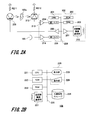
- FIG. 2A is a block diagram illustrating a hardware configuration of the sensor driving device 102.
- the sensor driving device 102 including a microcomputer includes a CPU 201, a ROM 202, a RAM 203, a first A / D converter 204, a second A / D converter 205, a first buffer 206 and a second buffer 207 constituting a serial port, and a bus 208. It is connected to the.
- the heart rate sensor 104 is configured by a set of, for example, a green LED 209 and a photodiode 210. A power supply voltage is applied to the anode of the LED 209 through a resistor R211.
- a power supply voltage is applied to the cathode of the photodiode 210 through a resistor R212.
- the cathode of the LED 209 is connected to the first buffer 206.
- a first buffer 206 which is a well-known CMOS inverter, functions as a switch that is controlled to be turned on and off through a bus 208 and that controls the connection between the cathode of the LED 209 and the ground node.
- a first A / D converter 204 is connected to the anode of the photodiode 210 through a first operational amplifier 213 that performs current-voltage conversion and voltage amplification, and changes in blood flow in the subject's outer ear 103a are converted into digital data.
- a second A / D converter 205 is connected to the heart sound microphone 105 through a second operational amplifier 214 that performs voltage amplification, and heart sounds detected from the subject's chest are converted into digital data.
- the short-range wireless communication unit 215 is connected to the second buffer 207 and transmits data output from the sensor driving device 102 to the information processing device 106 (see FIG. 1).
- FIG. 2B is a block diagram illustrating a hardware configuration of the information processing apparatus 106.
- the information processing apparatus 106 includes a CPU 221, a ROM 222, a RAM 223, a nonvolatile storage 224, a display unit 225, an operation unit 226, and a short-range wireless communication unit 227, and these members are connected to a bus 228.
- the display unit 225 is a liquid crystal display
- the operation unit 226 is an electrostatic position detection device.
- the display unit 225 and the operation unit 226 are overlapped to constitute a touch panel display 229.
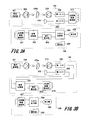
- FIG. 3A and 3B are block diagrams illustrating software functions of the blood pressure measurement system 101.
- FIG. 3A illustrates an example in which arithmetic processing for blood pressure measurement is performed by the information processing apparatus 106
- FIG. 3B illustrates blood pressure measurement.
- An example in the case where the arithmetic processing for the sensor driving device 102 is performed will be described.
- the LED 209 is intermittently driven to emit light by the light emission control unit 301 of the sensor driving device 102.
- the light emitted from the LED 209 passes through the outer ear 103a of the measurement subject 103, is detected by the photodiode 210, and is converted into heartbeat data by the first A / D converter 204.
- the heart sound detected from the subject's chest is detected by the heart sound microphone 105 and converted into heart sound data by the second A / D converter 205.
- Heartbeat data and heart sound data are transmitted to the information processing device 106 by the short-range wireless communication unit 215 of the sensor driving device 102.
- the information processing device 106 receives heart rate data and heart sound data from the sensor driving device 102 through the short-range wireless communication unit 227.
- heart sound data (hereinafter, abbreviated as “noise-removed heart sound data”) from which the heartbeat pulse and noise have been removed by the signal processing unit 302 of the information processing apparatus 106 is output.
- the blood pressure calculation unit 303 analyzes the noise-removed heart sound data obtained by the signal processing unit 302 and outputs blood pressure data.
- the heart rate pulse and blood pressure data are input to the input / output control unit 304 and displayed on the display unit 225 as heart rate values and blood pressure values.
- the LED 209 is intermittently driven to emit light by the light emission control unit 301 of the sensor driving device 102.
- the light emitted from the LED 209 passes through the outer ear 103a of the measurement subject 103, is detected by the photodiode 210, and is converted into heartbeat data by the first A / D converter 204.
- the heart sound detected from the subject's chest is detected by the heart sound microphone 105 and converted into heart sound data by the second A / D converter 205.
- the signal processing unit 302 receives heartbeat data and heart sound data, and outputs a heartbeat pulse and noise-removed heart sound data.
- the blood pressure calculation unit 303 analyzes the noise-removed heart sound data and outputs blood pressure data.
- the heartbeat pulse and blood pressure data are transmitted to the information processing device 106 by the short-range wireless communication unit 227 of the sensor driving device 102.
- the information processing device 106 receives the heart rate pulse and blood pressure data from the sensor driving device 102 through the short-range wireless communication unit 227.
- the heart rate pulse and blood pressure data are input to the input / output control unit 304 and displayed on the display unit 225 as a heart rate value and a blood pressure value.
- the functions of the signal processing unit 302 and the blood pressure calculation unit 303 may be implemented on either the information processing device 106 side or the sensor driving device 102 side.
- the signal processing unit 302 can also be referred to as a biological signal processing device that removes noise from heart sound data based on heart rate data and heart sound data.
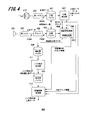
- FIG. 4 is a block diagram illustrating software functions of the signal processing unit 302.
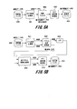
- 5A and 5B are block diagrams of software functions showing an example of the noise removal processing unit 411.
- the heartbeat signal output from the photodiode 210 constituting the heartbeat sensor 104 is converted into heartbeat data by the first A / D converter 204 and stored in the heartbeat buffer 401.
- the heart sound signal output from the heart sound microphone 105 is converted into heart sound data by the second A / D converter 205 and stored in the heart sound buffer 403 through the delay 402.
- the sampling frequency of the first A / D converter 204 and the second A / D converter 205 and the number of stored samples in the heart rate buffer 401 and the heart sound buffer 403 are configured to be equal.
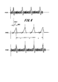
- FIG. 6 is a waveform diagram of heart sound data, heart rate data, and heart sound data delayed by the delay 402.
- the top waveform diagram in FIG. 6 is a waveform diagram of heart sound data at the detection point P404 in FIG.
- the second waveform diagram from the top is a waveform diagram of heartbeat data at the detection point P405 in FIG.
- the bottom waveform diagram is a waveform diagram of heart sound data delayed by the delay 402 at the detection point P406 in FIG.
- the delay 402 cancels this delay D601 and makes the phases of the heartbeat data stored in the heartbeat buffer 401 and the heart sound data stored in the heart sound buffer 403 coincide on the time axis.
- the heart rate detection unit 407 detects the heart rate peak address information and the heart rate range address information.
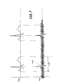
- FIG. 7 is a waveform diagram of heart rate data stored in the heart rate buffer 401 and heart sound data stored in the heart sound buffer 403. This is equivalent to an enlarged view of the lower two waveform diagrams of FIG.
- the heartbeat detection unit 407 looks at the heartbeat data stored in the heartbeat buffer 401 and outputs R-wave address information P701 and cut-out address information A702.
- the heartbeat waveform of a healthy person is composed of a P wave, a Q wave, an R wave, an S wave, and a T wave.
- the order of appearance of this waveform is fixed.
- the heart rate detection unit 407 calculates a virtual zero potential by arithmetic processing in order to remove the DC offset component from the heart rate data in the heart rate buffer 401.
- the R wave peak address in the heartbeat buffer 401 is detected. This is the R wave address information P701.
- the heartbeat detection unit 407 detects the start address of the P wave and the end address of the T wave that exist before and after the R wave address information P701. This is cut-out address information A702.
- a heartbeat interval that is, an RR interval (RR Interval) can be obtained.
- the heartbeat detection unit 407 acquires R wave address information P701 and outputs a heartbeat pulse.
- the heartbeat pulse is supplied to the input / output control unit 304 (see FIG. 3), and the input / output control unit 304 measures the heartbeat value from the interval of the heartbeat pulse.
- the rearrangement processing unit 408 performs rearrangement processing of heart sound data in the heart sound buffer 403 based on the R wave address information P701 and the cut-out address information A702 obtained from the heartbeat detection unit 407. Then, the rearranged data is output to the rearrangement buffer 409 as rearranged heart sound data and stored.
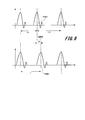
- FIG. 8 is a waveform diagram showing a heartbeat waveform before the rearrangement process and a heartbeat waveform subjected to the rearrangement process. An object to be actually subjected to the rearrangement processing is heart sound data.
- FIG. 8 is a waveform diagram showing a heartbeat waveform before the rearrangement process and a heartbeat waveform subjected to the rearrangement process.
- An object to be actually subjected to the rearrangement processing is heart sound data.
- FIG. 8 is a waveform diagram showing a heartbeat waveform before the rearrangement process and a heartbeat waveform subjected to the rearrangement process.
- the RR interval of a healthy person repeatedly increases and decreases periodically. That is, the RR interval is not always constant and continues to fluctuate. If orthogonal transformation such as discrete Fourier transformation is performed on the heart sound data as it is, removal of noise components becomes difficult due to periodic fluctuations. Therefore, before the heart sound data is input to the noise removal processing unit 411 by the subsequent orthogonal transformation, the waveforms of the heart sound data are forcibly arranged at equal intervals. First, the R-wave address information P701 was detected by the heartbeat detection unit 407. Therefore, the RR interval is obtained.
- the rearrangement processing unit 408 first extracts all RR intervals (distances between the R-wave address information P701) detected from the heartbeat buffer 401, and calculates an average value thereof. This is the RR average value. Next, the rearrangement processing unit 408 rearranges the R wave address information P701 detected by the heartbeat detection unit 407 into the RR average value intervals based on the RR average value. This is the rearranged R-wave address information P801. The rearrangement processing unit 408 cuts out the heart sound data in the heart sound buffer 403 based on the cut-out address information A702, and the cut-out heart sound data is an address that is the difference between the R-wave address information P701 and the rearranged R-wave address information P801.
- the movement amount G802 is moved and stored in the rearrangement buffer 409. If the heart sound data is simply cut out, noise is generated at the edge of the cut out heart sound data. Therefore, the rearranged heart sound in the rearrangement buffer 409 is obtained by the interpolation processing unit 410 provided in the rearrangement processing unit 408. Data interpolation processing is performed. As this interpolation processing, well-known linear interpolation, Lagrangian interpolation, spline interpolation, and the like can be used, and in particular, a Lagrange interpolation provides a good calculation result.
- the rearrangement processing unit 408 outputs rearrangement heart sound data and rearrangement R wave address information P801.
- the rearranged heart sound data is stored in the rearrangement buffer 409.
- the rearranged R-wave address information P801 is supplied to a later-described placement return processing unit 413, and together with the R-wave address information P701 and the cut-out address information A702 output from the heartbeat detection unit 407, Used for returning the position on the time axis to the original position.
- FIG. 5A is an example of a block diagram illustrating a software function of the noise removal processing unit 411 using discrete cosine transform.
- the rearranged heart sound data stored in the rearrangement buffer 409 which is a discrete data string, is converted into a coefficient data string having the same number of samples as the discrete data string by the DCT conversion processing unit 501.
- the coefficient data string is subjected to thinning processing of higher-order coefficient data by the coefficient filter 502.
- the coefficient data sequence subjected to the high-order coefficient data thinning-out processing is converted into the same number of decoded discrete data sequences as the discrete data sequence by the DCT inverse transform processing unit 503 and stored in the processed buffer 412.
- This decoded discrete data string becomes noise-removed rearranged heart sound data.
- FIG. 5B is an example of a block diagram illustrating a software function of the noise removal processing unit 411 using discrete Fourier transform.
- the rearranged heart sound data stored in the rearrangement buffer 409 which is a discrete data string, is converted into a complex data string having the same number of samples as the discrete data string by the FFT conversion processing unit 511.
- the real part data string and the imaginary part data string of the complex number data string are converted into an amplitude data string and frequency / phase data string of the same number as the number of samples of the discrete data string by the vector operation processing unit 512.
- LPF low-pass filter
- the amplitude data sequence and the frequency / phase data sequence from which the high-frequency components are discarded are converted into complex data sequences by the inverse vector calculation processing unit 514. Then, this complex data string is converted into a decoded discrete data string by the FFT inverse transform processing unit 515 and stored in the processed buffer 412. This decoded discrete data string becomes noise-removed rearranged heart sound data.
- the noise-removed rearranged heart sound data in the processed buffer 412 is returned to the state before the position of the heart waveform on the time axis is moved by the rearrangement processing unit 408 by the placement return processing unit 413. That is, based on the address information obtained by shifting the cut-out address information A702 based on the difference between the rearranged R-wave address information P801 and the R-wave address information P701, the heart waveform is obtained from the noise-relocated rearranged heart sound data in the processed buffer. cut. Then, the arrangement is restored based on the difference between the rearranged R-wave address information P801 and the R-wave address information P701, and is output as noise-removed heart sound data.
- Heart sounds include blood flow sounds.
- the sound of blood flow is sound generated by friction between the blood vessel inner wall and blood when blood flows through the blood vessel. Therefore, it has a strong correlation with the heartbeat cycle. Therefore, if only a frequency component having a strong correlation with the heartbeat cycle can be extracted from the heart sound, noise unrelated to the heartbeat cycle can be removed.
- the heartbeat cycle is not subtly constant.
- the heartbeat cycle includes fluctuations peculiar to living bodies. Therefore, R-wave address information P701 and cut-out address information A702 are extracted from the heartbeat data using the heartbeat detection unit 407.
- the rearrangement processing unit 408 calculates an average value of RR intervals from the R wave address information P701, and derives rearrangement R wave address information P801.
- the heart sound data synchronized with the heartbeat data is forcibly applied to the average value period.
- orthogonal transformation and orthogonal inverse transformation after applying the extracted heart sound waveform at equal intervals, it becomes possible to remove noise components unrelated to the heartbeat period from the heart sound.
- the waveform extracted by the orthogonal inverse transformation is returned to the basic heartbeat cycle based on the R wave address information P701, the rearranged R wave address information P801, and the cut address information A702. In this way, noise removal from the heart sound can be realized.
- the noise-removed heart sound data is input to the blood pressure calculation unit 303 as shown in FIGS. 3A and 3B.
- the blood pressure calculation unit 303 calculates the blood pressure by referring to the table inside the blood pressure calculation unit 303 for the amplitude of the noise-removed heart sound data.
- the blood pressure measurement system 101 has been disclosed.
- the blood pressure measurement system 101 can calculate the blood pressure by removing noise from the heart sound signal by providing the heart sound signal and the heartbeat signal.
- a heart sound signal is detected by an acoustic microphone
- a heartbeat signal is detected by a photoelectric sensor including an LED 209 and a photodiode 210.
- These sensors need to be in contact with the human body. If these sensors can be realized without contact with a human body, an in-vehicle blood pressure measurement system 901 incorporated in a passenger car or the like can be realized.
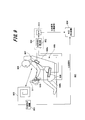
- FIG. 9 is a schematic diagram showing the overall configuration of the in-vehicle blood pressure measurement system 901.
- the in-vehicle blood pressure measurement system 901 includes a biological signal detection device 902, a heart sound detection device 903, and a blood pressure measurement device 904.
- the blood pressure measurement device 904 is equivalent to the signal processing unit 302 and the blood pressure calculation unit 303 of the blood pressure measurement system 101 described in the first embodiment.
- the heart sound detection device 903 irradiates the driver 906 with a weak radio wave of about 60 MHz from the helical antenna 905 and detects a heart sound signal from the reflected wave.
- the first antenna 907 is a metal plate approximately 5 to 10 cm square, and is embedded in the backrest 908a of the driver seat 908.
- the second antenna 909 is a metal plate of about 5 to 20 cm square, and is embedded in the sheet 908b of the driver sheet 908.
- the third antenna 910 is embedded as a metal wire in the steering 911 of the automobile. Further, the third antenna 910 may be embedded in a dashboard near the steering 911 instead of being embedded in the steering 911.
- the shape of the third antenna 910 is formed of a metal plate of about 5 to 10 cm square, similar to the first antenna 907 and the second antenna 909.
- the AC resistance detection unit 912 of the biological signal detection device 902 emits a weak unmodulated radio wave in the HF band of about several MHz to several tens of MHz from the first antenna 907. Then, radio waves are received from the second antenna 909 and the third antenna 910, respectively. Since the AC resistance detection unit 912 outputs a signal including a biological signal, a band-pass filter (hereinafter abbreviated as “BPF”) 913 removes a DC offset component and a high-frequency noise component, and generates a biological signal substantially equal to the electrocardiogram signal. Output. In this way, the biological signal obtained from the biological signal detection device 902 and the heart sound signal obtained from the heart sound detection device 903 are each input to the blood pressure measurement device 904, and the blood pressure of the measurement subject 103 is measured.
- BPF band-pass filter
- FIG. 10 is a functional block diagram of the biological signal detection device 902.
- the oscillation source 1001 generates an unmodulated high frequency signal in the HF band of about several MHz to several tens of MHz. This unmodulated high frequency signal is transmitted from the first antenna 907 as an unmodulated radio wave.
- a tuning circuit including a coil L1002 and a capacitor C1003 is connected to the second antenna 909.
- a tuning circuit including a coil L1004 and a capacitor C1005 is also connected to the third antenna 910.
- the output signal of the tuning circuit to which the second antenna 909 is connected is applied to the first mixer 1006.
- the first mixer 1006 also receives an unmodulated high frequency signal from the oscillation source 1001.
- the output signal of the tuning circuit to which the third antenna 910 is connected is applied to the second mixer 1007.
- An unmodulated high frequency signal from the oscillation source 1001 is input to the second mixer 1007 through the first ⁇ / 2 phase shift circuit 1008. That is, the second mixer 1007 receives a signal whose phase of the unmodulated high frequency signal from the oscillation source 1001 is delayed by ⁇ / 2.
- a dual gate FET or the like can be used as the first mixer 1006110 and the second mixer 1007112.
- the first mixer 1006 is supplied with the output signal of the tuning circuit to which the second antenna 909 is connected and the unmodulated high frequency signal of the oscillation source 1001. The sum signal and difference signal of these frequency components are supplied to the first mixer 1006. An output signal 1006 is supplied to the first LPF 1009. The first LPF 1009 outputs only the difference signal among the sum signal and difference signal of the input frequency components. The phase of the output signal of the first LPF 1009 is delayed by ⁇ / 2 by the second ⁇ / 2 phase shift circuit 1010.
- the second mixer 1007 is supplied with the output signal of the tuning circuit to which the third antenna 910 is connected and the signal obtained by phase-shifting the unmodulated high frequency signal of the oscillation source 1001 by ⁇ / 2, and these frequency components.
- the sum signal and the difference signal are supplied to the second LPF 1011 as the output signal of the second mixer 1007.
- the second LPF 1011 outputs only the difference signal among the sum signal and difference signal of the input frequency components.
- the output signal of the second ⁇ / 2 phase shift circuit 1010 and the output signal of the second LPF 1011 are input to the differential amplifier 1012, respectively.
- the differential amplifier 1012 cancels the in-phase component of the output signal of the second ⁇ / 2 phase shift circuit 1010 and the output signal of the second LPF 1011 and outputs only the anti-phase component.
- the output signal of the differential amplifier 1012 is input to the BPF 913.
- the first mixer 1006, the second mixer 1007, the first ⁇ / 2 phase shift circuit 1008, the first LPF 1009, the second ⁇ / 2 phase shift circuit 1010, and the second LPF 1011 have a well-known synchronization. Same as the detection circuit.
- a heartbeat that is, a change in blood pressure, causes a phenomenon of impedance change in the human body.
- An electrocardiogram signal substantially equal to the heartbeat signal is connected to electrodes at a plurality of locations on the human body, and a weak AC signal is sent to detect a change in impedance of the human body.
- the biological signal detection device 902 detects the impedance change of the human body in a non-contact manner using radio waves.
- the propagation of radio waves greatly fluctuates the gain of the detection signal on the reception side due to the presence of an object interposed between the transmission side and the reception side.
- the signal level on the receiving side fluctuates greatly only by the driver 906 who is the subject being measured moving even a little.
- a synchronous detection circuit is applied to the biological signal detection device 902 of this embodiment.
- the fluctuation of the signal level based on the movement of the human body is canceled out as an in-phase component by the differential amplifier 1012, and the fluctuation of the signal level based on the impedance change of the human body is differential. It is detected as an antiphase component by the amplifier 1012. That is, the change in impedance of the human body is equivalent to causing amplitude modulation with respect to an unmodulated high frequency signal.
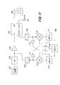
- FIG. 11 is a functional block diagram of the heart sound detection device 903.
- This heart sound detection device 903 has the technical contents of an application (Japanese Patent Application No. 2013-217093) filed by the inventor of the present application as a “pulse sensor”.
- the heart sound detection device 903 is divided into the following two elements.
- the first is an element that transmits a radio wave that is a traveling wave to an object and receives and extracts a reflected wave reflected from the object.
- the first element includes a pulse wave generator 1102, a BPF 1103, a first RF amplifier 1104, a directional coupler 1105, and a helical antenna 905 (fourth antenna).
- the second is an element that generates a frequency difference signal from a traveling wave and a reflected wave, and further extracts a pulse signal.
- the second element includes a second RF amplifier 1108, a third RF amplifier 1109, a third mixer 1110, a fourth mixer 1112, a third LPF 1114, a fourth LPF 1115, a differential amplifier 1116, and a fifth LPF 1117.
- a pulse wave generation unit 1102 that can be called a signal generation unit generates a pulse having a relatively low frequency.
- the frequency of the pulse generated by the pulse wave generator 1102 is, for example, 1 MHz.
- the BPF 1103 extracts a harmonic component from the pulse generated by the pulse wave generation unit 1102.
- the center frequency and bandwidth of the BPF 1103 are, for example, 60 MHz ⁇ 3 MHz.
- the first RF amplifier 1104 amplifies the harmonic component signal that has passed through the BPF 1103.
- the harmonic component signal amplified by the first RF amplifier 1104 is input to the input terminal (“IN” in FIG. 11) of the directional coupler 1105.
- the harmonic component signal is supplied to a helical antenna 905 connected to the output terminal (“OUT” in FIG. 11) of the directional coupler 1105.
- the directional coupler 1105 is a well-known circuit element formed of a coil, a capacitor, and a resistor and used for a VSWR meter (Voltage Standing Wave Ratio) or the like.
- the directional coupler 1105 can output an output signal proportional to the traveling wave and an output signal proportional to the reflected wave based on the traveling wave and the reflected wave included in the first transmission path.
- the helical antenna 905 emits radio waves having a plurality of frequencies based on the harmonic component signal.
- a radio wave reflected by an object such as a human body is received by the helical antenna 905, and a standing wave is generated inside the directional coupler 1105.
- a signal proportional to a radio wave signal (reflected wave) input from the output terminal through the helical antenna 905 is output to the separation terminal (“Isolated” in FIG. 11) of the directional coupler 1105.
- a signal proportional to the harmonic component signal (traveling wave) input to the input terminal is output to the coupling terminal (“Coupled” in FIG. 11) of the directional coupler 1105.
- the coupling terminal is connected to the ground node via the resistor R1107.
- a resistance value equal to the impedance of the directional coupler 1105 and the helical antenna 905 is set as the resistor R1107. In many cases, it is 50 ⁇ or 75 ⁇ .
- the second RF amplifier 1108 amplifies the harmonic component signal (traveling wave) that has passed through the BPF 1103.
- the third RF amplifier 1109 amplifies a radio wave signal (reflected wave) input from the output terminal through the helical antenna 905 and output from the separation terminal of the directional coupler 1105.
- the output signal of the second RF amplifier 1108 is supplied to the third mixer 1110 and also supplied to the fourth mixer 1112 via the inverting amplifier 1111.
- the output signal of the third RF amplifier 1109 is supplied to the fourth mixer 1112 and also supplied to the third mixer 1110 via the buffer 1113.
- the output signal of the second RF amplifier 1108 and the output signal of the third RF amplifier 1109 can obtain desired signals from the third mixer 1110 and the fourth mixer 1112 even if their phases are different. Therefore, a buffer (non-inverting amplifier) may be used instead of the inverting amplifier 1111. In this way, the third mixer 1110 and the fourth mixer 1112 output the multiplied signals of the traveling wave and the reflected wave, respectively.
- a dual gate FET or the like can be used as the third mixer 1110 and the fourth mixer 1112.
- the output signal of the third mixer 1110 is supplied to the third LPF 1114.
- the third LPF 1114 outputs a difference signal between the traveling wave and the reflected wave among the traveling wave and the reflected wave output from the third mixer 1110.
- the output signal of the fourth mixer 1112 is supplied to the fourth LPF 1115.
- the fourth LPF 1115 outputs a signal having a frequency difference between the traveling wave and the reflected wave among the traveling wave and reflected wave output signals output from the fourth mixer 1112.
- the output signal of the third LPF 1114 and the output signal of the fourth LPF 1115 are input to the differential amplifier 1116, respectively.
- a differential amplifier 1116 composed of an operational amplifier outputs a signal obtained by removing noise components from the output signal of the third LPF 1114 and the output signal of the fourth LPF 1115.
- the output signal of the differential amplifier 1116 is supplied to the fifth LPF 1117.
- the fifth LPF 1117 removes a relatively high frequency AC component from the output signal of the differential amplifier 1116 and passes a low frequency signal indicating the heart sound of the human body.
- the blood pressure measurement system 101 that can continuously measure the blood pressure without contact with the human body can be realized.
- the second ⁇ / 2 phase shift circuit 1010 connected to the subsequent stage of the first LPF 1009 in the biological signal detection device 902 shown in FIG. 10 may be connected to the subsequent stage of the second LPF 1011.
- the output signal of the first LPF 1009 is “USB + LSB” (Upper Side Band, Lower Side Band) in the synchronous detection circuit
- the output of the second ⁇ / 2 phase shift circuit 1010 connected to the subsequent stage of the second LPF 1011 is “USB-LSB” in the synchronous detection circuit.
- the differential amplifier 1012 outputs a USB signal.
- the blood pressure measurement system 101 in the first embodiment and the in-vehicle blood pressure measurement system 901 in the second embodiment are: A biological signal detection device 902 that outputs a heartbeat signal of the measurement subject 103; A heart sound detection device 903 for outputting a heart sound signal of the measurement subject 103;
- the configuration is the same as the blood pressure measurement device 904 that measures the blood pressure of the person 103 to be measured using the heartbeat signal output from the biological signal detection device 902 and the heart sound signal output from the heart sound detection device 903.
- the biological signal detection device 902 in the first embodiment is a heart rate sensor 104 that is worn on the outer ear 103a of the person 103 to be measured.
- the heart sound detection device 903 in the first embodiment is a heart sound microphone 105 that is attached to the chest of the person 103 to be measured.
- the blood pressure measurement method disclosed in Patent Document 1 utilizes the fact that there is a correlation between the amplitude of the heart sound and the blood pressure, and refers to a table using the correspondence between the amplitude of the heart sound and the blood pressure as data. It is based on technology that converts heartbeat amplitude into blood pressure data. By applying this technology, it is possible to prepare a table with the correspondence between the frequency of the signal constituting the heart sound and the blood pressure instead of the amplitude of the heart sound, and convert the frequency component of the heart sound into blood pressure data. It is.
- the blood pressure measurement system has been described.
- the signal processing unit 302 that can remove noise mixed in the heart sound signal using the heart sound signal and the heart beat signal has been described.
- This signal processing device 306 detects the R wave of the heartbeat signal accompanied by periodic fluctuations, and obtains the average value of the RR intervals. Then, the waveform of the heart sound signal with periodic fluctuations is forcibly rearranged at the average value interval of the RR interval in synchronization with the heartbeat signal. After the rearrangement, noise removal using orthogonal transformation and orthogonal inverse transformation is performed, and the obtained waveform arrangement is restored. By performing the rearrangement process before and after noise removal in this way, it is possible to effectively remove noise components unrelated to the heartbeat period.
- the biological signal detection device 902 that detects a heartbeat signal in a non-contact manner with respect to the measurement subject using radio waves has been described.
- Radio waves transmitted from the oscillation source 1001 through the first antenna 907 are received by the second antenna 909 and the third antenna 910, respectively, and synchronous detection is performed.
- the change in impedance of the person being measured, that is, the human body causes an effect equivalent to that of amplitude modulation to the unmodulated radio wave, and the gain fluctuation of the received radio wave caused by the presence of the human body is canceled by the differential amplifier 1012.
- synchronous detection in this way, a heartbeat signal can be detected in a non-contact manner with respect to the measurement subject.
- Each of the above-described configurations, functions, processing units, and the like may be realized by hardware by designing a part or all of them with, for example, an integrated circuit. Further, each of the above-described configurations, functions, and the like may be realized by software for interpreting and executing a program that realizes each function by the processor. Information such as programs, tables, and files that realize each function must be held in a volatile or non-volatile storage such as a memory, hard disk, or SSD (Solid State Drive), or a recording medium such as an IC card or an optical disk. Can do.
- the control lines and information lines are those that are considered necessary for the explanation, and not all the control lines and information lines on the product are necessarily shown. Actually, it may be considered that almost all the components are connected to each other.
- non-volatile storage 225 ... display unit, 226 ... operation unit, 227 ... short-range wireless communication unit, 228 ... bus 229 ... Touch panel display, 301 ... Light emission control unit, 302 ... Signal processing unit, 303 ... Blood pressure calculation unit, 304 ... Input / output control unit 401 ... heart rate buffer, 402 ... delay, 403 ... heart sound buffer, 407 ... heart rate detection unit, 408 ... rearrangement processing unit, 409 ... rearrangement buffer, 410 ... interpolation processing unit, 411 ... noise removal processing unit, 412 ... processed Buffers, 413: Arrangement return processing unit, 501 ... DCT conversion processing unit, 502 ... Coefficient filter, 503 ...
- DCT inverse conversion processing unit 511 ... FFT conversion processing unit, 512 ... Vector arithmetic processing unit, 513 ... Low pass filter, 514 ... Inverse vector calculation processing unit, 515... FFT inverse transformation processing unit, 901... Blood pressure measurement system for vehicle, 902... Biosignal detection device, 903... Heart sound detection device, 904.
Landscapes
- Health & Medical Sciences (AREA)
- Life Sciences & Earth Sciences (AREA)
- Engineering & Computer Science (AREA)
- Physics & Mathematics (AREA)
- General Health & Medical Sciences (AREA)
- Veterinary Medicine (AREA)
- Biomedical Technology (AREA)
- Heart & Thoracic Surgery (AREA)
- Medical Informatics (AREA)
- Molecular Biology (AREA)
- Surgery (AREA)
- Animal Behavior & Ethology (AREA)
- Public Health (AREA)
- Physiology (AREA)
- Pathology (AREA)
- Biophysics (AREA)
- Signal Processing (AREA)
- Artificial Intelligence (AREA)
- Computer Vision & Pattern Recognition (AREA)
- Psychiatry (AREA)
- Cardiology (AREA)
- Acoustics & Sound (AREA)
- Mathematical Physics (AREA)
- Vascular Medicine (AREA)
- Pulmonology (AREA)
- Nuclear Medicine, Radiotherapy & Molecular Imaging (AREA)
- Radiology & Medical Imaging (AREA)
- Measuring Pulse, Heart Rate, Blood Pressure Or Blood Flow (AREA)
- Measurement And Recording Of Electrical Phenomena And Electrical Characteristics Of The Living Body (AREA)
Abstract
発振源から第一アンテナを通じて送信する電波を、第二アンテナと第三アンテナとでそれぞれ受信し、同期検波を行う。被測定者、すなわち人体のインピーダンス変化は、無変調電波に対し振幅変調と同等の効果を生じさせ、人体の存在によって生じる受信電波のゲイン変動は、差動増幅器によって打ち消される。
Description
本発明は、周期性を有する生体信号を検出する生体信号検出装置と、生体信号から雑音を除去する生体信号処理装置と、これらを用いる血圧測定システムに関する。
心臓の動きに起因する心音は、血圧に由来する高い周波数成分が含まれている。この心音は血圧と強い相関性を持つことが知られており、計算機で心音データを適切に処理することで、血圧の類推が可能になる。
特許文献1には、心音を基に中心血圧を測定する中心血圧測定装置の技術内容が開示されている。
また、特許文献2には、心拍を検出する際にノイズ成分を除去する技術内容が開示されている。
特許文献1には、心音を基に中心血圧を測定する中心血圧測定装置の技術内容が開示されている。
また、特許文献2には、心拍を検出する際にノイズ成分を除去する技術内容が開示されている。
特許文献1に開示される中心血圧測定装置は、心音の採取に加速度センサを用いている。加速度センサは高価なので、装置のコストを抑えるために、できれば一般的なマイク(エレクトレットコンデンサマイク、ダイナミックマイク、セラミックマイク等)を利用することが好ましい。しかし、これら一般的なマイクを利用すると、被験者の衣服や皮膚、筋肉や骨等から発生するノイズも同時に拾ってしまう。
近年、被験者に常時装着が可能なウェアラブルセンサが市場で注目を集めているが、ウェアラブルセンサを実現するには低価格化、小型化と低消費電力化が必須条件である。血圧測定装置をウェアラブルセンサとして実現するには、低価格なマイクを利用しつつ、ノイズを効果的に除去する技術が不可欠である。
更に、脈拍センサや心電検出装置の代わりに電波を用いることができれば、非接触で心拍の連続検出が可能になる。
近年、被験者に常時装着が可能なウェアラブルセンサが市場で注目を集めているが、ウェアラブルセンサを実現するには低価格化、小型化と低消費電力化が必須条件である。血圧測定装置をウェアラブルセンサとして実現するには、低価格なマイクを利用しつつ、ノイズを効果的に除去する技術が不可欠である。
更に、脈拍センサや心電検出装置の代わりに電波を用いることができれば、非接触で心拍の連続検出が可能になる。
本発明は係る状況に鑑みてなされたものであり、電波を用いて生体信号を検出する生体信号検出装置と、生体信号から雑音を除去する生体信号処理装置と、これらを用いて連続的に被測定者の血圧を測定する血圧測定システムを提供することを目的とする。
上記課題を解決するために、本発明の信号雑音除去装置は、高周波信号を発生する発振源と、高周波信号に基づく電波を送信する第一アンテナと、第一アンテナから発される電波を受信する第二アンテナと、第一アンテナから発される電波を受信する第三アンテナと、高周波信号を用いて、第二アンテナから受信される電波と第三アンテナから受信される電波から変調信号を復調する同期検波回路とを具備する。
本発明によれば、電波を用いて生体信号を検出する生体信号検出装置と、生体信号から雑音を除去する生体信号処理装置と、これらを用いて連続的に被測定者の血圧を測定する血圧測定システムを提供することができる。
上記した以外の課題、構成及び効果は、以下の実施形態の説明により明らかにされる。
上記した以外の課題、構成及び効果は、以下の実施形態の説明により明らかにされる。
これより説明する実施形態では、先ず、血圧測定装置を構成する信号雑音除去装置を説明し、次に生体信号検出装置を説明する。
信号雑音除去装置は、特許文献2に開示される技術の改良である。
心音に混入するノイズを除去するために、本実施形態の信号雑音除去装置は、強力なノイズフィルタリング機能を有する直交変換と直交逆変換を用いる。
周知のように、直交変換は周期的信号の乗算処理を含む。この乗算処理により、特定の周波数以外の周波数成分は大幅に減衰される。この特徴はノイズフィルタとして極めて有用である。
ところで、心音は血流の音を含む。血流の音とは、血液が血管を流れる際に、血管内壁と血液との摩擦で生じる音である。したがって、心拍の周期と強い相関性(心拍周期の周波数の整数倍の周波数成分)を有する。
そこで、心音から、心拍周期と強い相関性を有する周波数成分だけを取り出すことができれば、心拍周期と無関係のノイズを除去できる。
しかし、心拍の周期は微妙に一定でない。心拍の周期には生体特有のゆらぎを含む。
そこで、心拍を脈拍センサで別途検出し、心拍のピークを検出して、心拍周期の平均値を算出し、心拍に同期する心音の信号波形を強制的にその平均値周期に当てはめる(リサンプル)。当てはめを行ってから直交変換、そして直交逆変換を施すことで、心音からノイズ成分の除去が可能になる。
直交逆変換後は、心拍のピークを検出した際に記憶しておいたバッファ内のアドレスに基づき、直交逆変換で取り出した波形を基の心拍周期に戻す。こうして、心音からノイズ除去を実現できる。
信号雑音除去装置は、特許文献2に開示される技術の改良である。
心音に混入するノイズを除去するために、本実施形態の信号雑音除去装置は、強力なノイズフィルタリング機能を有する直交変換と直交逆変換を用いる。
周知のように、直交変換は周期的信号の乗算処理を含む。この乗算処理により、特定の周波数以外の周波数成分は大幅に減衰される。この特徴はノイズフィルタとして極めて有用である。
ところで、心音は血流の音を含む。血流の音とは、血液が血管を流れる際に、血管内壁と血液との摩擦で生じる音である。したがって、心拍の周期と強い相関性(心拍周期の周波数の整数倍の周波数成分)を有する。
そこで、心音から、心拍周期と強い相関性を有する周波数成分だけを取り出すことができれば、心拍周期と無関係のノイズを除去できる。
しかし、心拍の周期は微妙に一定でない。心拍の周期には生体特有のゆらぎを含む。
そこで、心拍を脈拍センサで別途検出し、心拍のピークを検出して、心拍周期の平均値を算出し、心拍に同期する心音の信号波形を強制的にその平均値周期に当てはめる(リサンプル)。当てはめを行ってから直交変換、そして直交逆変換を施すことで、心音からノイズ成分の除去が可能になる。
直交逆変換後は、心拍のピークを検出した際に記憶しておいたバッファ内のアドレスに基づき、直交逆変換で取り出した波形を基の心拍周期に戻す。こうして、心音からノイズ除去を実現できる。
更に、特許文献1には、心音の振幅と血圧との相関性を利用して、血圧を推定する技術内容が開示されている。
上述の信号雑音除去装置が出力する、ノイズを除去した心音の信号をそのまま特許文献1に開示される血圧測定装置に入力すれば、マイクを用いた血圧測定装置を実現することができる。
更に、心音の周波数成分と血圧との相関性を利用すれば、信号雑音除去装置の直交変換から、直接的に血圧の推定も可能になる。
上述の信号雑音除去装置が出力する、ノイズを除去した心音の信号をそのまま特許文献1に開示される血圧測定装置に入力すれば、マイクを用いた血圧測定装置を実現することができる。
更に、心音の周波数成分と血圧との相関性を利用すれば、信号雑音除去装置の直交変換から、直接的に血圧の推定も可能になる。
生体信号検出装置は、心拍センサや心電検出装置の代わりに、電波を用いて非接触にて生体信号を検出する。人体のインピーダンスは心拍に応じて変動する。そこで、人体に電波を通過させ、そのインピーダンスの変化を検出する。しかし、人体に電波を通過させる際、人体が少しでも動いただけで電波の伝搬状態が大きく変動する。そこで、二つの受信モジュールを設け、同期検波と差動増幅を用いて、変動成分を打ち消すようにする。
[第一実施形態:血圧測定システムの全体構成]
図1は、血圧測定システム101の全体構成を示す概略図である。
センサ駆動装置102には、被測定者103の外耳103aに装着される心拍センサ104と、被測定者103の胸に装着される心音マイク105が接続される。センサ駆動装置102は、心拍センサ104から心拍信号を、心音マイク105から心音信号を検出し、BlueTooth(登録商標)等の近距離無線通信を用いて、スマートフォン等の携帯型無線端末106aや、パソコン106b等の情報処理装置106とデータ通信を行う。そして、心音から血圧を算出し、情報処理装置106の表示部に表示する。データ通信の詳細等については図3にて後述する。
図1は、血圧測定システム101の全体構成を示す概略図である。
センサ駆動装置102には、被測定者103の外耳103aに装着される心拍センサ104と、被測定者103の胸に装着される心音マイク105が接続される。センサ駆動装置102は、心拍センサ104から心拍信号を、心音マイク105から心音信号を検出し、BlueTooth(登録商標)等の近距離無線通信を用いて、スマートフォン等の携帯型無線端末106aや、パソコン106b等の情報処理装置106とデータ通信を行う。そして、心音から血圧を算出し、情報処理装置106の表示部に表示する。データ通信の詳細等については図3にて後述する。
[第一実施形態:センサ駆動装置102と情報処理装置106のハードウェア構成]
図2Aは、センサ駆動装置102のハードウェア構成を示すブロック図である。
マイコンを含むセンサ駆動装置102は、CPU201、ROM202、RAM203、第一A/D変換器204、第二A/D変換器205、シリアルポートを構成する第一バッファ206及び第二バッファ207がバス208に接続されている。
心拍センサ104は、例えば緑色のLED209と、フォトダイオード210の組で構成される。LED209のアノードには抵抗R211を通じて電源電圧が印加されている。フォトダイオード210のカソードには抵抗R212を通じて電源電圧が印加されている。
LED209のカソードは第一バッファ206に接続されている。周知のCMOSインバータである第一バッファ206はバス208を通じてオンオフ制御される、LED209のカソードと接地ノードとの接続を制御するスイッチとして機能する。フォトダイオード210のアノードには電流電圧変換と電圧増幅を行う第一オペアンプ213を通じて第一A/D変換器204が接続され、被験者の外耳103aにおける血流の変化がデジタルデータに変換される。
心音マイク105には電圧増幅を行う第二オペアンプ214を通じて第二A/D変換器205が接続され、被験者の胸から検出される心音がデジタルデータに変換される。
近距離無線通信部215は第二バッファ207に接続され、センサ駆動装置102が出力するデータを情報処理装置106(図1参照)へ送信する。
図2Aは、センサ駆動装置102のハードウェア構成を示すブロック図である。
マイコンを含むセンサ駆動装置102は、CPU201、ROM202、RAM203、第一A/D変換器204、第二A/D変換器205、シリアルポートを構成する第一バッファ206及び第二バッファ207がバス208に接続されている。
心拍センサ104は、例えば緑色のLED209と、フォトダイオード210の組で構成される。LED209のアノードには抵抗R211を通じて電源電圧が印加されている。フォトダイオード210のカソードには抵抗R212を通じて電源電圧が印加されている。
LED209のカソードは第一バッファ206に接続されている。周知のCMOSインバータである第一バッファ206はバス208を通じてオンオフ制御される、LED209のカソードと接地ノードとの接続を制御するスイッチとして機能する。フォトダイオード210のアノードには電流電圧変換と電圧増幅を行う第一オペアンプ213を通じて第一A/D変換器204が接続され、被験者の外耳103aにおける血流の変化がデジタルデータに変換される。
心音マイク105には電圧増幅を行う第二オペアンプ214を通じて第二A/D変換器205が接続され、被験者の胸から検出される心音がデジタルデータに変換される。
近距離無線通信部215は第二バッファ207に接続され、センサ駆動装置102が出力するデータを情報処理装置106(図1参照)へ送信する。
図2Bは、情報処理装置106のハードウェア構成を示すブロック図である。
情報処理装置106は、CPU221、ROM222、RAM223、不揮発性ストレージ224、表示部225、操作部226、そして近距離無線通信部227から構成され、これらの部材がバス228に接続されている。
ここで情報処理装置106がスマートフォン等の携帯型無線端末106aの場合、表示部225は液晶ディスプレイであり、操作部226は静電型位置検出装置である。そして、表示部225と操作部226は、重なりあってタッチパネルディスプレイ229を構成する。
情報処理装置106は、CPU221、ROM222、RAM223、不揮発性ストレージ224、表示部225、操作部226、そして近距離無線通信部227から構成され、これらの部材がバス228に接続されている。
ここで情報処理装置106がスマートフォン等の携帯型無線端末106aの場合、表示部225は液晶ディスプレイであり、操作部226は静電型位置検出装置である。そして、表示部225と操作部226は、重なりあってタッチパネルディスプレイ229を構成する。
[第一実施形態:センサ駆動装置102と情報処理装置106のソフトウェア機能]
図3A及び図3Bは、血圧測定システム101のソフトウェア機能を示すブロック図であり、図3Aは血圧測定のための演算処理を情報処理装置106で行う場合の例を示し、図3Bは血圧測定のための演算処理をセンサ駆動装置102で行う場合の例を示す。
図3Aの例では、LED209は、センサ駆動装置102の発光制御部301によって間歇発光駆動される。このLED209が発する光は、被測定者103の外耳103aを透過してフォトダイオード210によって検出され、第一A/D変換器204によって心拍データに変換される。
被験者の胸から検出される心音は心音マイク105によって検出され、第二A/D変換器205によって心音データに変換される。
心拍データと心音データは、センサ駆動装置102の近距離無線通信部215によって情報処理装置106に送信される。
情報処理装置106は、センサ駆動装置102から近距離無線通信部227を通じて心拍データと心音データを受信する。すると、情報処理装置106の信号処理部302によって心拍パルスとノイズが除去された心音データ(以下「ノイズ除去心音データ」と略す)が出力される。血圧算出部303は、信号処理部302で得られるノイズ除去心音データを解析し、血圧データを出力する。そして、心拍パルスと血圧データは入出力制御部304に入力され、心拍値と血圧値として表示部225に表示される。
図3A及び図3Bは、血圧測定システム101のソフトウェア機能を示すブロック図であり、図3Aは血圧測定のための演算処理を情報処理装置106で行う場合の例を示し、図3Bは血圧測定のための演算処理をセンサ駆動装置102で行う場合の例を示す。
図3Aの例では、LED209は、センサ駆動装置102の発光制御部301によって間歇発光駆動される。このLED209が発する光は、被測定者103の外耳103aを透過してフォトダイオード210によって検出され、第一A/D変換器204によって心拍データに変換される。
被験者の胸から検出される心音は心音マイク105によって検出され、第二A/D変換器205によって心音データに変換される。
心拍データと心音データは、センサ駆動装置102の近距離無線通信部215によって情報処理装置106に送信される。
情報処理装置106は、センサ駆動装置102から近距離無線通信部227を通じて心拍データと心音データを受信する。すると、情報処理装置106の信号処理部302によって心拍パルスとノイズが除去された心音データ(以下「ノイズ除去心音データ」と略す)が出力される。血圧算出部303は、信号処理部302で得られるノイズ除去心音データを解析し、血圧データを出力する。そして、心拍パルスと血圧データは入出力制御部304に入力され、心拍値と血圧値として表示部225に表示される。
図3Bの例でも、LED209は、センサ駆動装置102の発光制御部301によって間歇発光駆動される。そしてLED209が発する光は、被測定者103の外耳103aを透過してフォトダイオード210によって検出され、第一A/D変換器204によって心拍データに変換される。
被験者の胸から検出される心音は心音マイク105によって検出され、第二A/D変換器205によって心音データに変換される。
信号処理部302は、心拍データと心音データを受けて、心拍パルスとノイズ除去心音データを出力する。血圧算出部303はノイズ除去心音データを解析し、血圧データを出力する。心拍パルスと血圧データは、センサ駆動装置102の近距離無線通信部227によって情報処理装置106に送信される。
情報処理装置106は、センサ駆動装置102から近距離無線通信部227を通じて心拍パルスと血圧データを受信する。心拍パルスと血圧データは入出力制御部304に入力され、心拍値と血圧値として表示部225に表示される。
被験者の胸から検出される心音は心音マイク105によって検出され、第二A/D変換器205によって心音データに変換される。
信号処理部302は、心拍データと心音データを受けて、心拍パルスとノイズ除去心音データを出力する。血圧算出部303はノイズ除去心音データを解析し、血圧データを出力する。心拍パルスと血圧データは、センサ駆動装置102の近距離無線通信部227によって情報処理装置106に送信される。
情報処理装置106は、センサ駆動装置102から近距離無線通信部227を通じて心拍パルスと血圧データを受信する。心拍パルスと血圧データは入出力制御部304に入力され、心拍値と血圧値として表示部225に表示される。
すなわち、信号処理部302と血圧算出部303の機能は、情報処理装置106側と、センサ駆動装置102側のどちらに実装してもよい。
信号処理部302は、心拍データと心音データを基に、心音データからノイズを除去する、生体信号処理装置ということもできる。
信号処理部302は、心拍データと心音データを基に、心音データからノイズを除去する、生体信号処理装置ということもできる。
[第一実施形態:信号処理部302のソフトウェア機能]
図4は、信号処理部302のソフトウェア機能を示すブロック図である。
図5A及び図5Bは、ノイズ除去処理部411の一例を示すソフトウェア機能のブロック図である。
心拍センサ104を構成するフォトダイオード210が出力する心拍信号は、第一A/D変換器204によって心拍データに変換され、心拍バッファ401に格納される。一方、心音マイク105が出力する心音信号は、第二A/D変換器205によって心音データに変換され、ディレイ402を通じて心音バッファ403に格納される。第一A/D変換器204と第二A/D変換器205のサンプリング周波数、そして心拍バッファ401と心音バッファ403の格納サンプル数は等しく構成されている。
図4は、信号処理部302のソフトウェア機能を示すブロック図である。
図5A及び図5Bは、ノイズ除去処理部411の一例を示すソフトウェア機能のブロック図である。
心拍センサ104を構成するフォトダイオード210が出力する心拍信号は、第一A/D変換器204によって心拍データに変換され、心拍バッファ401に格納される。一方、心音マイク105が出力する心音信号は、第二A/D変換器205によって心音データに変換され、ディレイ402を通じて心音バッファ403に格納される。第一A/D変換器204と第二A/D変換器205のサンプリング周波数、そして心拍バッファ401と心音バッファ403の格納サンプル数は等しく構成されている。
ここで、一旦、図6を参照して、心拍バッファ401と心音バッファ403とディレイ402の作用を説明する。
図6は、心音データと心拍データと、ディレイ402により遅延された心音データの波形図である。
図6中、一番上の波形図は、図4の検出点P404における、心音データの波形図である。 図6中、上から二番目の波形図は、図4の検出点P405における、心拍データの波形図である。
図6中、一番下の波形図は、図4の検出点P406における、ディレイ402によって遅延された心音データの波形図である。
人体の心臓付近から発される心音と、外耳103aから検出される心拍には、心臓と外耳103aとの距離に基づく時間軸上の遅延D601が存在する。ディレイ402はこの遅延D601を打ち消し、心拍バッファ401に格納される心拍データと、心音バッファ403に格納される心音データとの位相を時間軸上で一致させる。
図6は、心音データと心拍データと、ディレイ402により遅延された心音データの波形図である。
図6中、一番上の波形図は、図4の検出点P404における、心音データの波形図である。 図6中、上から二番目の波形図は、図4の検出点P405における、心拍データの波形図である。
図6中、一番下の波形図は、図4の検出点P406における、ディレイ402によって遅延された心音データの波形図である。
人体の心臓付近から発される心音と、外耳103aから検出される心拍には、心臓と外耳103aとの距離に基づく時間軸上の遅延D601が存在する。ディレイ402はこの遅延D601を打ち消し、心拍バッファ401に格納される心拍データと、心音バッファ403に格納される心音データとの位相を時間軸上で一致させる。
再度図4に戻って、信号処理部302の説明を続ける。
心拍バッファ401内の心拍データは、心拍検出部407によって心拍のピークのアドレス情報と、心拍の範囲のアドレス情報が検出される。
ここで、一旦図7を参照して、心拍データと心音データとを比較して、心拍検出部407が検出するアドレス情報について説明する。
図7は、心拍バッファ401に格納されている心拍データと、心音バッファ403に格納されている心音データの波形図である。図6の下二つの波形図を拡大したものと等価である。
心拍検出部407は、心拍バッファ401に格納されている心拍データを見て、R波アドレス情報P701と、切り出しアドレス情報A702を出力する。
一般に、健常者の心拍波形は、P波、Q波、R波、S波、そしてT波よりなる。この波形の出現順序は決まっている。
先ず、心拍検出部407は心拍バッファ401内における心拍データから、DCオフセット成分を除去するべく、仮想的なゼロ電位を演算処理にて算出する。そして、心拍バッファ401内におけるR波のピークのアドレスを検出する。これがR波アドレス情報P701である。
次に、心拍検出部407は仮想的なゼロ電位に基づいて、R波アドレス情報P701の前後に存在する、P波の始まりのアドレスと、T波の終わりのアドレスを検出する。これが切り出しアドレス情報A702である。
心拍バッファ401内のR波アドレス情報P701を取得すると、心拍間隔、すなわちRR間隔(RR Interval)を得ることができる。
なお、心拍検出部407はR波アドレス情報P701を取得すると共に、心拍パルスも出力する。この心拍パルスは入出力制御部304(図3参照)に供給され、入出力制御部304は心拍パルスの間隔から心拍値を計測する。
心拍バッファ401内の心拍データは、心拍検出部407によって心拍のピークのアドレス情報と、心拍の範囲のアドレス情報が検出される。
ここで、一旦図7を参照して、心拍データと心音データとを比較して、心拍検出部407が検出するアドレス情報について説明する。
図7は、心拍バッファ401に格納されている心拍データと、心音バッファ403に格納されている心音データの波形図である。図6の下二つの波形図を拡大したものと等価である。
心拍検出部407は、心拍バッファ401に格納されている心拍データを見て、R波アドレス情報P701と、切り出しアドレス情報A702を出力する。
一般に、健常者の心拍波形は、P波、Q波、R波、S波、そしてT波よりなる。この波形の出現順序は決まっている。
先ず、心拍検出部407は心拍バッファ401内における心拍データから、DCオフセット成分を除去するべく、仮想的なゼロ電位を演算処理にて算出する。そして、心拍バッファ401内におけるR波のピークのアドレスを検出する。これがR波アドレス情報P701である。
次に、心拍検出部407は仮想的なゼロ電位に基づいて、R波アドレス情報P701の前後に存在する、P波の始まりのアドレスと、T波の終わりのアドレスを検出する。これが切り出しアドレス情報A702である。
心拍バッファ401内のR波アドレス情報P701を取得すると、心拍間隔、すなわちRR間隔(RR Interval)を得ることができる。
なお、心拍検出部407はR波アドレス情報P701を取得すると共に、心拍パルスも出力する。この心拍パルスは入出力制御部304(図3参照)に供給され、入出力制御部304は心拍パルスの間隔から心拍値を計測する。
再度図4に戻って、信号処理部302の説明を続ける。
再配置処理部408は、心拍検出部407から得られたR波アドレス情報P701と切り出しアドレス情報A702に基いて、心音バッファ403内の心音データの再配置処理を行う。そして、再配置を施したデータを再配置心音データとして再配置バッファ409に出力し、これを格納する。
ここで、一旦図8を参照して、心拍データを用いて、再配置処理部408の再配置処理について説明する。
図8は、再配置処理前の心拍波形と、再配置処理を施した心拍波形を示す波形図である。実際に再配置処理を行う対象は心音データであるが、理解を容易にするために、心拍波形で再配置処理部408による処理を行う例について説明する。
再配置処理部408は、心拍検出部407から得られたR波アドレス情報P701と切り出しアドレス情報A702に基いて、心音バッファ403内の心音データの再配置処理を行う。そして、再配置を施したデータを再配置心音データとして再配置バッファ409に出力し、これを格納する。
ここで、一旦図8を参照して、心拍データを用いて、再配置処理部408の再配置処理について説明する。
図8は、再配置処理前の心拍波形と、再配置処理を施した心拍波形を示す波形図である。実際に再配置処理を行う対象は心音データであるが、理解を容易にするために、心拍波形で再配置処理部408による処理を行う例について説明する。
健常者のRR間隔は、周期的に増減を繰り返すことが知られている。すなわち、RR間隔は常に一定ではなく、変動し続けている。心音データをこのままの状態で離散フーリエ変換等の直交変換を施すと、周期的な変動によってノイズ成分の除去が困難になる。そこで、後段の直交変換によるノイズ除去処理部411に心音データを投入する前に、心音データの波形を強制的に等間隔に並べる。 先に、心拍検出部407でR波アドレス情報P701を検出していた。したがって、RR間隔を得ている。再配置処理部408は先ず、心拍バッファ401から検出される全てのRR間隔(R波アドレス情報P701同士の距離)を取り出し、その平均値を算出する。これがRR平均値である。次に、再配置処理部408はRR平均値に基づいて、心拍検出部407が検出したR波アドレス情報P701をRR平均値の間隔に並べ直す。これが再配置R波アドレス情報P801である。
そして、再配置処理部408は心音バッファ403内の心音データを切り出しアドレス情報A702に基いて切り出し、切り出した心音データを、R波アドレス情報P701と再配置R波アドレス情報P801との差であるアドレス移動量G802だけ移動させ、再配置バッファ409に格納する。単純に心音データを切り出すと、切り出した心音データの縁の部分でノイズが発生してしまうので、再配置処理部408の中に設けられる補間処理部410によって、再配置バッファ409内の再配置心音データの補間処理が行われる。この補間処理は周知の直線補間、ラグランジェ補間、スプライン補間等が利用可能であり、特にラグランジェ補間が良い演算結果を得る。
そして、再配置処理部408は心音バッファ403内の心音データを切り出しアドレス情報A702に基いて切り出し、切り出した心音データを、R波アドレス情報P701と再配置R波アドレス情報P801との差であるアドレス移動量G802だけ移動させ、再配置バッファ409に格納する。単純に心音データを切り出すと、切り出した心音データの縁の部分でノイズが発生してしまうので、再配置処理部408の中に設けられる補間処理部410によって、再配置バッファ409内の再配置心音データの補間処理が行われる。この補間処理は周知の直線補間、ラグランジェ補間、スプライン補間等が利用可能であり、特にラグランジェ補間が良い演算結果を得る。
こうして再配置処理部408は、再配置心音データと、再配置R波アドレス情報P801を出力する。再配置心音データは再配置バッファ409に格納される。再配置R波アドレス情報P801は、後述する配置復帰処理部413に供給され、心拍検出部407が出力するR波アドレス情報P701と切り出しアドレス情報A702と共に、ノイズ除去済再配置心音データの心音波形の時間軸上の位置を元に戻す処理に使用される。
再配置バッファ409に格納される再配置心音データは、ノイズ除去処理部411によってノイズが除去される。ノイズ除去処理部411は直交変換と直交逆変換を用いて、ノイズの除去を行う。直交変換には様々な手法が知られているが、代表的な二つの直交変換を用いたノイズ除去について、図5A及び図5Bにて説明する。
図5Aは、離散コサイン変換を用いたノイズ除去処理部411のソフトウェア機能を示すブロック図の例である。
離散データ列である再配置バッファ409に格納される再配置心音データは、DCT変換処理部501によって、離散データ列のサンプル数と同数の係数データ列に変換される。係数データ列は係数フィルタ502によって、高次係数データの間引き処理が行われる。高次係数データの間引き処理が施された係数データ列は、DCT逆変換処理部503によって、離散データ列と同数の復号離散データ列に変換され、処理済バッファ412に格納される。
この復号離散データ列が、ノイズ除去済再配置心音データとなる。
図5Aは、離散コサイン変換を用いたノイズ除去処理部411のソフトウェア機能を示すブロック図の例である。
離散データ列である再配置バッファ409に格納される再配置心音データは、DCT変換処理部501によって、離散データ列のサンプル数と同数の係数データ列に変換される。係数データ列は係数フィルタ502によって、高次係数データの間引き処理が行われる。高次係数データの間引き処理が施された係数データ列は、DCT逆変換処理部503によって、離散データ列と同数の復号離散データ列に変換され、処理済バッファ412に格納される。
この復号離散データ列が、ノイズ除去済再配置心音データとなる。
図5Bは、離散フーリエ変換を用いたノイズ除去処理部411のソフトウェア機能を示すブロック図の例である。
離散データ列である再配置バッファ409に格納される再配置心音データは、FFT変換処理部511によって、離散データ列のサンプル数と同数の複素数データ列に変換される。複素数データ列の実部データ列と虚部データ列はベクトル演算処理部512によって、離散データ列のサンプル数と同数の振幅データ列と周波数・位相データ列に変換される。振幅データ列はローパスフィルタ(以下「LPF」と略)513によって高周波成分が捨象される。高周波成分が捨象された振幅データ列と周波数・位相データ列は逆ベクトル演算処理部514によって複素数データ列に変換される。そして、この複素数データ列はFFT逆変換処理部515によって復号離散データ列に変換され、処理済バッファ412に格納される。
この復号離散データ列が、ノイズ除去済再配置心音データとなる。
離散データ列である再配置バッファ409に格納される再配置心音データは、FFT変換処理部511によって、離散データ列のサンプル数と同数の複素数データ列に変換される。複素数データ列の実部データ列と虚部データ列はベクトル演算処理部512によって、離散データ列のサンプル数と同数の振幅データ列と周波数・位相データ列に変換される。振幅データ列はローパスフィルタ(以下「LPF」と略)513によって高周波成分が捨象される。高周波成分が捨象された振幅データ列と周波数・位相データ列は逆ベクトル演算処理部514によって複素数データ列に変換される。そして、この複素数データ列はFFT逆変換処理部515によって復号離散データ列に変換され、処理済バッファ412に格納される。
この復号離散データ列が、ノイズ除去済再配置心音データとなる。
処理済バッファ412内のノイズ除去済再配置心音データは、配置復帰処理部413によって、心音波形の時間軸上の位置が再配置処理部408によって移動される前の状態に戻される。すなわち、切り出しアドレス情報A702を再配置R波アドレス情報P801とR波アドレス情報P701との差に基いてずらしたアドレス情報を基に、処理済みバッファ内のノイズ除去済再配置心音データから心音波形を切り出す。そして、再配置R波アドレス情報P801とR波アドレス情報P701との差に基いて配置の復帰を行い、ノイズ除去済心音データとして出力する。
心音は血流の音を含む。血流の音とは、血液が血管を流れる際に、血管内壁と血液との摩擦で生じる音である。したがって、心拍の周期と強い相関性を有する。
そこで、心音から、心拍周期と強い相関性を有する周波数成分だけを取り出すことができれば、心拍周期と無関係のノイズを除去できる。
しかし、心拍の周期は微妙に一定でない。心拍の周期には生体特有のゆらぎを含む。
そこで、心拍データから心拍検出部407を用いてR波アドレス情報P701と切り出しアドレス情報A702を取り出す。次に、再配置処理部408はR波アドレス情報P701からRR間隔の平均値を算出し、再配置R波アドレス情報P801を導き出す。そして、心拍データに同期する心音データを強制的にその平均値周期に当てはめる。切り出した心音波形を等間隔に当てはめを行ってから直交変換、そして直交逆変換を施すことで、心音から心拍の周期と無関係なノイズ成分の除去が可能になる。
直交逆変換後は、R波アドレス情報P701と再配置R波アドレス情報P801と切り出しアドレス情報A702に基づき、直交逆変換で取り出した波形を基の心拍周期に戻す。こうして、心音からのノイズ除去を実現することができる。
そこで、心音から、心拍周期と強い相関性を有する周波数成分だけを取り出すことができれば、心拍周期と無関係のノイズを除去できる。
しかし、心拍の周期は微妙に一定でない。心拍の周期には生体特有のゆらぎを含む。
そこで、心拍データから心拍検出部407を用いてR波アドレス情報P701と切り出しアドレス情報A702を取り出す。次に、再配置処理部408はR波アドレス情報P701からRR間隔の平均値を算出し、再配置R波アドレス情報P801を導き出す。そして、心拍データに同期する心音データを強制的にその平均値周期に当てはめる。切り出した心音波形を等間隔に当てはめを行ってから直交変換、そして直交逆変換を施すことで、心音から心拍の周期と無関係なノイズ成分の除去が可能になる。
直交逆変換後は、R波アドレス情報P701と再配置R波アドレス情報P801と切り出しアドレス情報A702に基づき、直交逆変換で取り出した波形を基の心拍周期に戻す。こうして、心音からのノイズ除去を実現することができる。
ノイズ除去済心音データは、図3A及び図3Bに示されるように、血圧算出部303に入力される。血圧算出部303は、ノイズ除去済心音データの振幅を血圧算出部303内部のテーブルを参照して、血圧を算出する。
[第二実施形態:生体信号検出装置の全体構成]
第一実施形態では、血圧測定システム101を開示した。第一実施形態の血圧測定システム101は、心音信号と心拍信号を与えることで、心音信号からノイズを除去し、血圧を算出できる。血圧測定システム101では、心音信号を音響マイクで、心拍信号をLED209とフォトダイオード210よりなる光電センサで検出していた。これらセンサは人体と接触する必要がある。もし、これらのセンサを人体に非接触で実現できれば、乗用車等に組み込む車載用血圧測定システム901を実現できる。
第一実施形態では、血圧測定システム101を開示した。第一実施形態の血圧測定システム101は、心音信号と心拍信号を与えることで、心音信号からノイズを除去し、血圧を算出できる。血圧測定システム101では、心音信号を音響マイクで、心拍信号をLED209とフォトダイオード210よりなる光電センサで検出していた。これらセンサは人体と接触する必要がある。もし、これらのセンサを人体に非接触で実現できれば、乗用車等に組み込む車載用血圧測定システム901を実現できる。
図9は車載用血圧測定システム901の全体構成を示す概略図である。
車載用血圧測定システム901は、生体信号検出装置902と、心音検出装置903と、血圧測定装置904よりなる。このうち血圧測定装置904は、第一実施形態で説明した血圧測定システム101の、信号処理部302及び血圧算出部303と等価である。
心音検出装置903は、ヘリカルアンテナ905から凡そ60MHz程度の微弱な電波を運転者906に照射して、その反射波から心音信号を検出する。
車載用血圧測定システム901は、生体信号検出装置902と、心音検出装置903と、血圧測定装置904よりなる。このうち血圧測定装置904は、第一実施形態で説明した血圧測定システム101の、信号処理部302及び血圧算出部303と等価である。
心音検出装置903は、ヘリカルアンテナ905から凡そ60MHz程度の微弱な電波を運転者906に照射して、その反射波から心音信号を検出する。
生体信号検出装置902には、3つのアンテナが接続されている。
第一アンテナ907は凡そ5~10cm四方の金属板であり、ドライバーシート908の背もたれ908aに埋め込まれている。
第二アンテナ909も第一アンテナ907と同様、凡そ5~20cm四方の金属板であり、ドライバーシート908のシート908bに埋め込まれている。
第三アンテナ910は自動車のステアリング911に金属線として埋め込まれる。また、第三アンテナ910はステアリング911に埋め込む代わりに、ステアリング911近傍のダッシュボードに埋め込んでもよい。その際、第三アンテナ910の形状は第一アンテナ907及び第二アンテナ909と同様の、凡そ5~10cm四方の金属板で形成される。
第一アンテナ907は凡そ5~10cm四方の金属板であり、ドライバーシート908の背もたれ908aに埋め込まれている。
第二アンテナ909も第一アンテナ907と同様、凡そ5~20cm四方の金属板であり、ドライバーシート908のシート908bに埋め込まれている。
第三アンテナ910は自動車のステアリング911に金属線として埋め込まれる。また、第三アンテナ910はステアリング911に埋め込む代わりに、ステアリング911近傍のダッシュボードに埋め込んでもよい。その際、第三アンテナ910の形状は第一アンテナ907及び第二アンテナ909と同様の、凡そ5~10cm四方の金属板で形成される。
生体信号検出装置902の交流抵抗検出部912は、第一アンテナ907から数MHz~数十MHz程度の、HF帯の微弱な無変調電波を発する。そして、第二アンテナ909と第三アンテナ910からそれぞれ電波を受信する。交流抵抗検出部912は、生体信号を含む信号を出力するので、バンドパスフィルタ(以下「BPF」と略)913でDCオフセット成分と高周波ノイズ成分を除去し、心電信号に略等しい生体信号を出力する。
こうして、生体信号検出装置902から得られる生体信号と、心音検出装置903から得られる心音信号は、それぞれ血圧測定装置904に入力され、被測定者103の血圧が測定される。
こうして、生体信号検出装置902から得られる生体信号と、心音検出装置903から得られる心音信号は、それぞれ血圧測定装置904に入力され、被測定者103の血圧が測定される。
図10は、生体信号検出装置902の機能ブロック図である。
発振源1001は数MHz~数十MHz程度の、HF帯の無変調高周波信号を生成する。この無変調高周波信号は第一アンテナ907から無変調電波として送信される。
第二アンテナ909には、コイルL1002とコンデンサC1003よりなる同調回路が接続されている。第三アンテナ910にも、コイルL1004とコンデンサC1005よりなる同調回路が接続されている。
第二アンテナ909が接続されている同調回路の出力信号は、第一ミキサ1006に印加される。第一ミキサ1006には発振源1001の無変調高周波信号も入力される。
第三アンテナ910が接続されている同調回路の出力信号は、第二ミキサ1007に印加される。第二ミキサ1007には、発振源1001の無変調高周波信号が、第一π/2移相回路1008を通じて入力される。すなわち、第二ミキサ1007には発振源1001の無変調高周波信号がπ/2だけ位相が遅れた信号が入力される。なお、第一ミキサ1006110と第二ミキサ1007112は、例えばデュアルゲートFET等が利用可能である。
発振源1001は数MHz~数十MHz程度の、HF帯の無変調高周波信号を生成する。この無変調高周波信号は第一アンテナ907から無変調電波として送信される。
第二アンテナ909には、コイルL1002とコンデンサC1003よりなる同調回路が接続されている。第三アンテナ910にも、コイルL1004とコンデンサC1005よりなる同調回路が接続されている。
第二アンテナ909が接続されている同調回路の出力信号は、第一ミキサ1006に印加される。第一ミキサ1006には発振源1001の無変調高周波信号も入力される。
第三アンテナ910が接続されている同調回路の出力信号は、第二ミキサ1007に印加される。第二ミキサ1007には、発振源1001の無変調高周波信号が、第一π/2移相回路1008を通じて入力される。すなわち、第二ミキサ1007には発振源1001の無変調高周波信号がπ/2だけ位相が遅れた信号が入力される。なお、第一ミキサ1006110と第二ミキサ1007112は、例えばデュアルゲートFET等が利用可能である。
第一ミキサ1006には、第二アンテナ909が接続されている同調回路の出力信号と、発振源1001の無変調高周波信号とが供給され、これらの周波数成分の和信号と差信号が第一ミキサ1006の出力信号として、第一LPF1009に供給される。第一LPF1009は、入力された周波数成分の和信号と差信号のうち、差信号のみを出力する。そして、第一LPF1009の出力信号は、第二π/2移相回路1010によってπ/2だけ位相が遅延される。
第二ミキサ1007には、第三アンテナ910が接続されている同調回路の出力信号と、発振源1001の無変調高周波信号がπ/2移相された信号とが供給され、これらのの周波数成分の和信号と差信号が第二ミキサ1007の出力信号として、第二LPF1011に供給される。第二LPF1011は、入力された周波数成分の和信号と差信号のうち、差信号のみを出力する。
第二π/2移相回路1010の出力信号と、第二LPF1011の出力信号は、それぞれ差動増幅器1012に入力される。差動増幅器1012は、第二π/2移相回路1010の出力信号と、第二LPF1011の出力信号の同相成分を打ち消し、逆相成分のみを出力する。そして、差動増幅器1012の出力信号はBPF913に入力される。
二つの同調回路を除けば、第一ミキサ1006、第二ミキサ1007、第一π/2移相回路1008、第一LPF1009、第二π/2移相回路1010、第二LPF1011は、周知の同期検波回路と変わらない。
第二ミキサ1007には、第三アンテナ910が接続されている同調回路の出力信号と、発振源1001の無変調高周波信号がπ/2移相された信号とが供給され、これらのの周波数成分の和信号と差信号が第二ミキサ1007の出力信号として、第二LPF1011に供給される。第二LPF1011は、入力された周波数成分の和信号と差信号のうち、差信号のみを出力する。
第二π/2移相回路1010の出力信号と、第二LPF1011の出力信号は、それぞれ差動増幅器1012に入力される。差動増幅器1012は、第二π/2移相回路1010の出力信号と、第二LPF1011の出力信号の同相成分を打ち消し、逆相成分のみを出力する。そして、差動増幅器1012の出力信号はBPF913に入力される。
二つの同調回路を除けば、第一ミキサ1006、第二ミキサ1007、第一π/2移相回路1008、第一LPF1009、第二π/2移相回路1010、第二LPF1011は、周知の同期検波回路と変わらない。
心拍、すなわち血流の圧力変化は、人体のインピーダンス変化という現象をもたらす。心拍信号に略等しい心電信号は、人体の複数箇所に電極を接続して、微弱な交流信号を流して、人体のインピーダンス変化を検出する。本実施形態の生体信号検出装置902は、電波を用いて、この人体のインピーダンス変化を非接触で検出する。
しかし、電波の伝搬は送信側と受信側との間に介在する物体の存在により、受信側の検出信号のゲインが大幅に変動する。図9の場合、被測定者である運転者906が少しでも動いただけで、受信側の信号レベルが大幅に変動する。
そこで、本実施形態の生体信号検出装置902は、同期検波回路を応用した。受信側にアンテナと同調回路を二つ設けることで、人体の動きに基づく信号レベルの変動は、差動増幅器1012で同相成分として打ち消され、人体のインピーダンス変化に基づく信号レベルの変動は、差動増幅器1012で逆相成分として検出される。すなわち、人体のインピーダンス変化は、無変調高周波信号に対し、振幅変調を生じさせることと等価となる。
しかし、電波の伝搬は送信側と受信側との間に介在する物体の存在により、受信側の検出信号のゲインが大幅に変動する。図9の場合、被測定者である運転者906が少しでも動いただけで、受信側の信号レベルが大幅に変動する。
そこで、本実施形態の生体信号検出装置902は、同期検波回路を応用した。受信側にアンテナと同調回路を二つ設けることで、人体の動きに基づく信号レベルの変動は、差動増幅器1012で同相成分として打ち消され、人体のインピーダンス変化に基づく信号レベルの変動は、差動増幅器1012で逆相成分として検出される。すなわち、人体のインピーダンス変化は、無変調高周波信号に対し、振幅変調を生じさせることと等価となる。
図11は、心音検出装置903の機能ブロック図である。この心音検出装置903は、本願の発明者が「脈拍センサ」として出願済(特願2013-217093号)の技術内容である。
心音検出装置903は、以下に記す、二つの要素に分けられる。
第一は、対象物に進行波である電波を送信し、対象物から反射される反射波を受信して抽出する要素である。この第一の要素には、パルス波生成部1102、BPF1103、第一RF増幅器1104、方向性結合器1105及びヘリカルアンテナ905(第四アンテナ)が含まれる。
第二は、進行波と反射波から周波数差信号を生成し、更に脈拍の信号を抽出する要素である。この第二の要素としては、第二RF増幅器1108、第三RF増幅器1109、第三ミキサ1110、第四ミキサ1112、第三LPF1114、第四LPF1115、差動増幅器1116及び第五LPF1117が含まれる。
心音検出装置903は、以下に記す、二つの要素に分けられる。
第一は、対象物に進行波である電波を送信し、対象物から反射される反射波を受信して抽出する要素である。この第一の要素には、パルス波生成部1102、BPF1103、第一RF増幅器1104、方向性結合器1105及びヘリカルアンテナ905(第四アンテナ)が含まれる。
第二は、進行波と反射波から周波数差信号を生成し、更に脈拍の信号を抽出する要素である。この第二の要素としては、第二RF増幅器1108、第三RF増幅器1109、第三ミキサ1110、第四ミキサ1112、第三LPF1114、第四LPF1115、差動増幅器1116及び第五LPF1117が含まれる。
信号生成部ともいえるパルス波生成部1102は、比較的低い周波数のパルスを生成する。このパルス波生成部1102で生成されるパルスの周波数は、例えば1MHzである。
BPF1103は、パルス波生成部1102が生成したパルスから高調波成分を取り出す。BPF1103の中心周波数と帯域幅は、例えば60MHz±3MHzである。BPF1103は例えばLC共振回路を多段接続した回路構成が利用可能である。
第一RF増幅器1104は、BPF1103を通過した高調波成分の信号を増幅する。
BPF1103は、パルス波生成部1102が生成したパルスから高調波成分を取り出す。BPF1103の中心周波数と帯域幅は、例えば60MHz±3MHzである。BPF1103は例えばLC共振回路を多段接続した回路構成が利用可能である。
第一RF増幅器1104は、BPF1103を通過した高調波成分の信号を増幅する。
第一RF増幅器1104によって増幅された高調波成分の信号は、方向性結合器1105の入力端子(図11中「IN」)に入力される。そして、この高調波成分の信号は方向性結合器1105の出力端子(図11中「OUT」)に接続されたヘリカルアンテナ905に供給される。
方向性結合器1105は、コイル、コンデンサ及び抵抗で形成され、VSWR計(電圧定在波比:Voltage Standing Wave Ratio)等に用いられる周知の回路素子である。方向性結合器1105は、第一の伝送路に含まれる進行波と反射波に基づいて、進行波に比例した出力信号と、反射波に比例した出力信号とをそれぞれ出力することができる。
方向性結合器1105は、コイル、コンデンサ及び抵抗で形成され、VSWR計(電圧定在波比:Voltage Standing Wave Ratio)等に用いられる周知の回路素子である。方向性結合器1105は、第一の伝送路に含まれる進行波と反射波に基づいて、進行波に比例した出力信号と、反射波に比例した出力信号とをそれぞれ出力することができる。
ヘリカルアンテナ905は、高調波成分の信号に基づく、複数の周波数の電波を発する。そして、人体等の対象物によって反射された電波は、ヘリカルアンテナ905によって受信され、方向性結合器1105の内部で定在波を生じる。
方向性結合器1105の分離端子(図11中「Isolated」)には、ヘリカルアンテナ905を通じて出力端子から入力される電波の信号(反射波)に比例した信号が出力される。
方向性結合器1105の結合端子(図11中「Coupled」)には、入力端子に入力される高調波成分の信号(進行波)に比例した信号が出力される。
結合端子は、抵抗R1107を介して接地ノードに接続されている。抵抗R1107としては方向性結合器1105及びヘリカルアンテナ905のインピーダンスに等しい抵抗値が設定される。多くの場合、50Ωか75Ωである。
方向性結合器1105の分離端子(図11中「Isolated」)には、ヘリカルアンテナ905を通じて出力端子から入力される電波の信号(反射波)に比例した信号が出力される。
方向性結合器1105の結合端子(図11中「Coupled」)には、入力端子に入力される高調波成分の信号(進行波)に比例した信号が出力される。
結合端子は、抵抗R1107を介して接地ノードに接続されている。抵抗R1107としては方向性結合器1105及びヘリカルアンテナ905のインピーダンスに等しい抵抗値が設定される。多くの場合、50Ωか75Ωである。
第二RF増幅器1108は、BPF1103を通過した高調波成分の信号(進行波)を増幅する。
第三RF増幅器1109は、方向性結合器1105の分離端子から出力される、ヘリカルアンテナ905を通じて出力端子から入力される電波の信号(反射波)を増幅する。
第二RF増幅器1108の出力信号は、第三ミキサ1110に供給されると共に、反転増幅器1111を介して第四ミキサ1112に供給される。
第三RF増幅器1109の出力信号は、第四ミキサ1112に供給されると共に、バッファ1113を介して第三ミキサ1110に供給される。なお、第二RF増幅器1108の出力信号と第三RF増幅器1109の出力信号は、位相が異なっていても所望の信号を第三ミキサ1110及び第四ミキサ1112から得られる。したがって、反転増幅器1111の代わりにバッファ(非反転増幅器)を用いてもよい。
こうして、第三ミキサ1110と第四ミキサ1112は、それぞれ進行波と反射波の乗算信号を出力する。ここで、第三ミキサ1110と第四ミキサ1112としては、例えばデュアルゲートFET等が利用可能である。
第三RF増幅器1109は、方向性結合器1105の分離端子から出力される、ヘリカルアンテナ905を通じて出力端子から入力される電波の信号(反射波)を増幅する。
第二RF増幅器1108の出力信号は、第三ミキサ1110に供給されると共に、反転増幅器1111を介して第四ミキサ1112に供給される。
第三RF増幅器1109の出力信号は、第四ミキサ1112に供給されると共に、バッファ1113を介して第三ミキサ1110に供給される。なお、第二RF増幅器1108の出力信号と第三RF増幅器1109の出力信号は、位相が異なっていても所望の信号を第三ミキサ1110及び第四ミキサ1112から得られる。したがって、反転増幅器1111の代わりにバッファ(非反転増幅器)を用いてもよい。
こうして、第三ミキサ1110と第四ミキサ1112は、それぞれ進行波と反射波の乗算信号を出力する。ここで、第三ミキサ1110と第四ミキサ1112としては、例えばデュアルゲートFET等が利用可能である。
第三ミキサ1110の出力信号は、第三LPF1114に供給される。第三LPF1114は、第三ミキサ1110から出力される進行波と反射波の乗算信号のうち、進行波と反射波の、それぞれの周波数の差の信号を出力する。
同様に、第四ミキサ1112の出力信号は、第四LPF1115に供給される。第四LPF1115は、第四ミキサ1112から出力される進行波と反射波の乗算信号のうち、進行波と反射波の周波数の差の信号を出力する。
第三LPF1114の出力信号と、第四LPF1115の出力信号は、それぞれ差動増幅器1116に入力される。オペアンプよりなる差動増幅器1116は、第三LPF1114の出力信号と、第四LPF1115の出力信号からノイズ成分を除去した信号を出力する。
差動増幅器1116の出力信号は、第五LPF1117に供給される。第五LPF1117は、差動増幅器1116の出力信号から比較的高い周波数の交流成分を除去して、人体の心音を示す低周波信号を通過させる。
同様に、第四ミキサ1112の出力信号は、第四LPF1115に供給される。第四LPF1115は、第四ミキサ1112から出力される進行波と反射波の乗算信号のうち、進行波と反射波の周波数の差の信号を出力する。
第三LPF1114の出力信号と、第四LPF1115の出力信号は、それぞれ差動増幅器1116に入力される。オペアンプよりなる差動増幅器1116は、第三LPF1114の出力信号と、第四LPF1115の出力信号からノイズ成分を除去した信号を出力する。
差動増幅器1116の出力信号は、第五LPF1117に供給される。第五LPF1117は、差動増幅器1116の出力信号から比較的高い周波数の交流成分を除去して、人体の心音を示す低周波信号を通過させる。
以上説明したように、第一実施形態で説明した技術内容に基づく血圧測定装置904に、本実施形態で説明した生体信号検出装置902が出力する心拍信号と、心音検出装置903が出力する心音信号を与えることで、人体に非接触でかつ連続的に血圧を測定できる血圧測定システム101を実現することができる。
以上説明した実施形態には、以下に記す応用例が可能である。
(1)図10に示した生体信号検出装置902の、第一LPF1009の後段に接続されている第二π/2移相回路1010は、第二LPF1011の後段に接続してもよい。この時、第一LPF1009の出力信号は、同期検波回路における「USB+LSB」(Upper Side Band, Lower Side Band)であり、第二LPF1011の後段に接続される第二π/2移相回路1010の出力信号は、同期検波回路における「USB-LSB」である。そして差動増幅器1012は、USBの信号を出力することとなる。
(1)図10に示した生体信号検出装置902の、第一LPF1009の後段に接続されている第二π/2移相回路1010は、第二LPF1011の後段に接続してもよい。この時、第一LPF1009の出力信号は、同期検波回路における「USB+LSB」(Upper Side Band, Lower Side Band)であり、第二LPF1011の後段に接続される第二π/2移相回路1010の出力信号は、同期検波回路における「USB-LSB」である。そして差動増幅器1012は、USBの信号を出力することとなる。
(2)第一実施形態における血圧測定システム101と、第二実施形態における車載用血圧測定システム901は、
被測定者103の心拍信号を出力する生体信号検出装置902と、
前記被測定者103の心音信号を出力する心音検出装置903と、
前記生体信号検出装置902から出力される心拍信号と、前記心音検出装置903から出力される心音信号を用いて、被測定者103の血圧を測定する血圧測定装置904という構成において等しい。
第一実施形態における生体信号検出装置902は、被測定者103の外耳103aに装着する心拍センサ104である。
第一実施形態における心音検出装置903は、被測定者103の胸に貼付する心音マイク105である。
被測定者103の心拍信号を出力する生体信号検出装置902と、
前記被測定者103の心音信号を出力する心音検出装置903と、
前記生体信号検出装置902から出力される心拍信号と、前記心音検出装置903から出力される心音信号を用いて、被測定者103の血圧を測定する血圧測定装置904という構成において等しい。
第一実施形態における生体信号検出装置902は、被測定者103の外耳103aに装着する心拍センサ104である。
第一実施形態における心音検出装置903は、被測定者103の胸に貼付する心音マイク105である。
(3)特許文献1に開示される血圧測定方法は、心音の振幅と血圧に相関性があることを利用して、心音の振幅と血圧との対応関係をデータにしたテーブルを参照して、心音の振幅を血圧のデータに変換する技術を基礎としている。この技術内容を応用し、心音の振幅の代わりに、心音を構成する信号の周波数と血圧の対応関係をデータにしたテーブルを用意して、心音の周波数成分から血圧のデータに変換することが可能である。この場合、ノイズ除去処理部411の内部から、心音を構成する周波数に関する情報を取り出すことで、心音の周波数成分から血液データへの変換が実現できるので、図5AのDCT逆変換処理部503又は図5BのFFT逆変換処理部515、そして図4の配置復帰処理部413が不要になる。
本実施形態では、血圧測定システムについて説明した。
第一実施形態の血圧測定システム101では、特に心音信号と心拍信号を用いて心音信号に混入するノイズを除去することが可能な信号処理部302について説明した。この信号処理装置306は、周期的変動を伴う心拍信号のR波を検出して、RR間隔の平均値を求める。そして、心拍信号と同期して周期的変動を伴う心音信号の波形を、強制的にRR間隔の平均値の間隔に再配置する。再配置後、直交変換、直交逆変換を用いたノイズ除去を行い、得られた波形の配置を元に戻す。このように再配置処理をノイズ除去の前後に行うことで、心拍の周期と無関係なノイズ成分を効果的に除去することができる。
第一実施形態の血圧測定システム101では、特に心音信号と心拍信号を用いて心音信号に混入するノイズを除去することが可能な信号処理部302について説明した。この信号処理装置306は、周期的変動を伴う心拍信号のR波を検出して、RR間隔の平均値を求める。そして、心拍信号と同期して周期的変動を伴う心音信号の波形を、強制的にRR間隔の平均値の間隔に再配置する。再配置後、直交変換、直交逆変換を用いたノイズ除去を行い、得られた波形の配置を元に戻す。このように再配置処理をノイズ除去の前後に行うことで、心拍の周期と無関係なノイズ成分を効果的に除去することができる。
第二実施形態の車載用血圧測定システム901では、電波を用いて被測定者に対し非接触にて心拍信号を検出する、生体信号検出装置902について説明した。発振源1001から第一アンテナ907を通じて送信する電波を、第二アンテナ909と第三アンテナ910とでそれぞれ受信し、同期検波を行う。被測定者、すなわち人体のインピーダンス変化は、無変調電波に対し振幅変調と同等の効果を生じさせ、人体の存在によって生じる受信電波のゲイン変動は、差動増幅器1012によって打ち消される。このように同期検波を用いることにより、被測定者に対し非接触にて心拍信号を検出できる。
以上、本発明の実施形態について説明したが、本発明は上記実施形態に限定されるものではなく、請求の範囲に記載した本発明の要旨を逸脱しない限りにおいて、他の変形例、応用例を含む。
例えば、上記した実施形態は本発明をわかりやすく説明するために装置及びシステムの構成を詳細にかつ具体的に説明したものであり、必ずしも説明した全ての構成を備えるものに限定されるものではない。また、ある実施形態の構成の一部を他の実施形態の構成に置き換えることは可能であり、更にはある実施形態の構成に他の実施形態の構成を加えることも可能である。また、各実施形態の構成の一部について、他の構成の追加・削除・置換をすることも可能である。
また、上記の各構成、機能、処理部等は、それらの一部又は全部を、例えば集積回路で設計するなどによりハードウェアで実現してもよい。また、上記の各構成、機能等は、プロセッサがそれぞれの機能を実現するプログラムを解釈し、実行するためのソフトウェアで実現してもよい。各機能を実現するプログラム、テーブル、ファイル等の情報は、メモリや、ハードディスク、SSD(Solid State Drive)等の揮発性あるいは不揮発性のストレージ、または、ICカード、光ディスク等の記録媒体に保持することができる。
また、制御線や情報線は説明上必要と考えられるものを示しており、製品上必ずしもすべての制御線や情報線を示しているとは限らない。実際には殆ど全ての構成が相互に接続されていると考えてもよい。
例えば、上記した実施形態は本発明をわかりやすく説明するために装置及びシステムの構成を詳細にかつ具体的に説明したものであり、必ずしも説明した全ての構成を備えるものに限定されるものではない。また、ある実施形態の構成の一部を他の実施形態の構成に置き換えることは可能であり、更にはある実施形態の構成に他の実施形態の構成を加えることも可能である。また、各実施形態の構成の一部について、他の構成の追加・削除・置換をすることも可能である。
また、上記の各構成、機能、処理部等は、それらの一部又は全部を、例えば集積回路で設計するなどによりハードウェアで実現してもよい。また、上記の各構成、機能等は、プロセッサがそれぞれの機能を実現するプログラムを解釈し、実行するためのソフトウェアで実現してもよい。各機能を実現するプログラム、テーブル、ファイル等の情報は、メモリや、ハードディスク、SSD(Solid State Drive)等の揮発性あるいは不揮発性のストレージ、または、ICカード、光ディスク等の記録媒体に保持することができる。
また、制御線や情報線は説明上必要と考えられるものを示しており、製品上必ずしもすべての制御線や情報線を示しているとは限らない。実際には殆ど全ての構成が相互に接続されていると考えてもよい。
101…血圧測定システム、102…センサ駆動装置、103…被測定者、104…心拍センサ、105…心音マイク、106…情報処理装置、201…CPU、202…ROM、203…RAM、204…第一A/D変換器、205…第二A/D変換器、206…第一バッファ、207…第二バッファ、208…バス、209…LED、210…フォトダイオード、213…第一オペアンプ、214…第二オペアンプ、215…近距離無線通信部、221…CPU、222…ROM、223…RAM、224…不揮発性ストレージ、225…表示部、226…操作部、227…近距離無線通信部、228…バス、229…タッチパネルディスプレイ、301…発光制御部、302…信号処理部、303…血圧算出部、304…入出力制御部、401…心拍バッファ、402…ディレイ、403…心音バッファ、407…心拍検出部、408…再配置処理部、409…再配置バッファ、410…補間処理部、411…ノイズ除去処理部、412…処理済バッファ、413…配置復帰処理部、501…DCT変換処理部、502…係数フィルタ、503…DCT逆変換処理部、511…FFT変換処理部、512…ベクトル演算処理部、513…ローパスフィルタ、514…逆ベクトル演算処理部、515…FFT逆変換処理部、901…車載用血圧測定システム、902…生体信号検出装置、903…心音検出装置、904…血圧測定装置、905…ヘリカルアンテナ、906…運転者、907…第一アンテナ、908…ドライバーシート、909…第二アンテナ、910…第三アンテナ、911…ステアリング、912…交流抵抗検出部、913…BPF、1001…発振源、1006…第一ミキサ、1007…第二ミキサ、1008…第一π/2移相回路、1009…第一LPF、1010…第二π/2移相回路、1011…第二LPF、1012…差動増幅器、1102…パルス波生成部、1103…BPF、1104…第一RF増幅器、1105…方向性結合器、1108…第二RF増幅器、1109…第三RF増幅器、1110…第三ミキサ、1111…反転増幅器、1112…第四ミキサ、1113…バッファ、1114…第三LPF、1115…第四LPF、1116…差動増幅器、1117…第五LPF
Claims (7)
- 高周波信号を発生する発振源と、
前記高周波信号に基づく電波を送信する第一アンテナと、
前記第一アンテナから発される前記電波を受信する第二アンテナと、
前記第一アンテナから発される前記電波を受信する第三アンテナと、
前記高周波信号を用いて、前記第二アンテナから受信される前記電波と前記第三アンテナから受信される前記電波から変調信号を復調する同期検波回路と
を具備する、生体信号検出装置。 - 前記同期検波回路は、
前記第二アンテナから受信される電波と前記高周波信号との乗算信号を出力する第一ミキサと、
前記高周波信号をπ/2位相をずらす第一π/2移相回路と、
前記第三アンテナから受信される電波と前記第一π/2移相回路の出力信号との乗算信号を出力する第二ミキサと、
前記第一ミキサの出力信号から、周波数差信号を出力する第一LPFと、
前記第二ミキサの出力信号から、周波数差信号を出力する第二LPFと、
前記第一LPF又は第二LPFの何れかの信号をπ/2位相をずらす第二π/2移相回路と、
前記第二π/2移相回路の出力信号と、前記第一LPF又は前記第二LPFの、前記第二π/2移相回路によって位相がずらされていない側の信号との差成分の信号を出力する差動増幅器と
を具備する、請求項1に記載の生体信号検出装置。 - 生体信号検出装置と、心音検出装置と、血圧測定装置とを具備する血圧測定システムであって、
前記生体信号検出装置は、
高周波信号を発生する発振源と、
前記高周波信号に基づく電波を送信する第一アンテナと、
前記第一アンテナから発される前記電波を受信する第二アンテナと、
前記第一アンテナから発される前記電波を受信する第三アンテナと、
前記高周波信号を用いて、前記第二アンテナから受信される前記電波と前記第三アンテナから受信される前記電波から変調信号を復調する同期検波回路と
を具備し、
前記心音検出装置は、
所定の帯域幅を有する第二の高周波信号を発生する信号生成部と、
前記第二の高周波信号に基づく第二の電波を送信する第四アンテナと、
前記信号生成部と前記第四アンテナに接続される方向性結合器と、
前記方向性結合器の出力信号から人体の心音に相当する信号を出力する差動増幅器と
を具備し、
前記血圧測定装置は、前記生体信号検出装置から出力される心拍信号と、前記心音検出装置から出力される心音信号を用いて、被測定者の血圧を測定する、血圧測定システム。 - 被測定者の心拍信号を出力する生体信号検出装置から出力される前記心拍信号のデータである心拍データが格納される心拍バッファと、
前記被測定者の心音信号を出力する心音検出装置から出力される前記心音信号のデータである心音データが格納される心音バッファと、
前記心拍データから心拍波形におけるR波のアドレスを示すR波アドレス情報と、心拍波形の範囲を示す切り出しアドレス情報を出力する心拍検出部と、 前記R波アドレス情報と前記切り出しアドレス情報に基いて前記心音データから所望のデータ部分を切り出した上で、前記心音バッファ内の前記心音データと前記R波アドレス情報からRR間隔の平均値であるRR平均値を算出して、前記データ部分を再配置して、再配置心音データを形成する再配置処理部と、
前記再配置心音データから直交変換及び直交逆変換を用いてノイズ成分を除去してノイズ除去済再配置心音データを形成するノイズ除去処理部と、
前記R波アドレス情報と前記切り出しアドレス情報を用いて、前記ノイズ除去済再配置心音データの時間軸上の配置を前記心音バッファ内の前記心音データの状態に戻す配置復帰処理部と
を具備する、生体信号処理装置。 - 前記ノイズ除去処理部は、
入力される離散データ列をDCT変換して係数データ列に変換するDCT変換処理部と、
前記係数データ列の高次係数データの間引き処理を行う係数フィルタと、
前記係数フィルタから出力されるデータ列をDCT逆変換して復号離散データ列を生成するDCT逆変換処理部と
を具備する、請求項4に記載の生体信号処理装置。 - 前記ノイズ除去処理部は、
入力される離散データ列をFFT変換して複素データ列に変換するFFT変換処理部と、
前記複素データ列を振幅データ列と周波数・位相データ列に変換するベクトル演算処理部と、
前記振幅データ列から高周波成分を除去するLPFと、
前記LPFの出力データ列と前記周波数・位相データ列から復号複素データ列に変換する逆ベクトル演算処理部と、
前記復号複素データ列をFFT逆変換して復号離散データ列を生成するFFT逆変換処理部と
を具備する、請求項4に記載の生体信号処理装置。 - 被測定者の心拍信号を出力する生体信号検出装置と、
前記被測定者の心音信号を出力する心音検出装置と、
前記心拍信号と前記心音信号を基に、前記心音信号からノイズを除去したノイズ除去済心音データを出力する生体信号処理装置と、
前記ノイズ除去済心音データに基いて、被測定者の血圧を測定する血圧算出部と
を具備する、血圧測定システムであって、
前記生体信号処理装置は、
前記心拍信号のデータである心拍データが格納される心拍バッファと、
前記心音信号のデータである心音データが格納される心音バッファと、
前記心拍データから心拍波形におけるR波のアドレスを示すR波アドレス情報と、心拍波形の範囲を示す切り出しアドレス情報を出力する心拍検出部と、
前記R波アドレス情報と前記切り出しアドレス情報に基いて前記心音データから所望のデータ部分を切り出した上で、前記心音バッファ内の前記心音データと前記R波アドレス情報からRR間隔の平均値であるRR平均値を算出して、前記データ部分を再配置して、再配置心音データを形成する再配置処理部と、
前記再配置心音データから直交変換及び直交逆変換を用いてノイズ成分を除去してノイズ除去済再配置心音データを形成するノイズ除去処理部と、
前記R波アドレス情報と前記切り出しアドレス情報を用いて、前記ノイズ除去済再配置心音データの時間軸上の配置を前記心音バッファ内の前記心音データの状態に戻す配置復帰処理部と
を具備する、血圧測定システム。
Priority Applications (1)
| Application Number | Priority Date | Filing Date | Title |
|---|---|---|---|
| US15/555,674 US20180042499A1 (en) | 2015-03-05 | 2016-03-07 | Biological signal detecting device, biological signal processing device, and blood pressure measuring system |
Applications Claiming Priority (2)
| Application Number | Priority Date | Filing Date | Title |
|---|---|---|---|
| JP2015043523A JP6445354B2 (ja) | 2015-03-05 | 2015-03-05 | 生体信号検出装置及び血圧測定システム |
| JP2015-043523 | 2015-03-05 |
Publications (1)
| Publication Number | Publication Date |
|---|---|
| WO2016140367A1 true WO2016140367A1 (ja) | 2016-09-09 |
Family
ID=56843839
Family Applications (1)
| Application Number | Title | Priority Date | Filing Date |
|---|---|---|---|
| PCT/JP2016/056957 Ceased WO2016140367A1 (ja) | 2015-03-05 | 2016-03-07 | 生体信号検出装置、生体信号処理装置及び血圧測定システム |
Country Status (3)
| Country | Link |
|---|---|
| US (1) | US20180042499A1 (ja) |
| JP (1) | JP6445354B2 (ja) |
| WO (1) | WO2016140367A1 (ja) |
Cited By (4)
| Publication number | Priority date | Publication date | Assignee | Title |
|---|---|---|---|---|
| WO2019044195A1 (ja) * | 2017-08-31 | 2019-03-07 | 株式会社村田製作所 | 心拍測定装置 |
| CN110267598A (zh) * | 2017-01-09 | 2019-09-20 | 皇家飞利浦有限公司 | 一种处理由对象产生的呼吸声音的听诊器装置和方法 |
| EP3603514A4 (en) * | 2017-03-28 | 2020-11-11 | Kyushu Institute of Technology | EMOTION ESTIMATE APPARATUS |
| US11950885B2 (en) | 2018-08-23 | 2024-04-09 | Mitsubishi Electric Corporation | Biosensor device |
Families Citing this family (8)
| Publication number | Priority date | Publication date | Assignee | Title |
|---|---|---|---|---|
| JP6388447B2 (ja) * | 2015-03-23 | 2018-09-12 | 国立大学法人九州工業大学 | 生体信号処理装置及び血圧測定システム |
| WO2019035337A1 (ja) | 2017-08-15 | 2019-02-21 | テイ・エス テック株式会社 | 生体センサーの配置構造 |
| EP3684260B1 (en) * | 2017-09-20 | 2023-01-25 | Cardiac Pacemakers, Inc. | Devices and methods for heart sound detection |
| JP7226694B2 (ja) * | 2018-01-24 | 2023-02-21 | ゲンサーム インコーポレイテッド | ハンドル上の乗員の手または座席内の乗員の存在を感知するためのハンドルまたは座席用の静電容量感知・加熱システム |
| KR102608633B1 (ko) * | 2018-02-08 | 2023-12-04 | 삼성전자주식회사 | 전자 장치 및 그 제어 방법 |
| JP7001627B2 (ja) * | 2019-03-01 | 2022-01-19 | Kddi株式会社 | 感情特定装置、感情特定方法及びメッセージ出力システム |
| CN113116313B (zh) * | 2019-12-31 | 2025-03-18 | 裴璇 | 一种采用调制电信号的非相干光源进行光电脉搏波检测的系统及方法 |
| JP7476813B2 (ja) | 2021-01-27 | 2024-05-01 | 株式会社Soken | 生体情報検出装置 |
Citations (4)
| Publication number | Priority date | Publication date | Assignee | Title |
|---|---|---|---|---|
| JP2006304963A (ja) * | 2005-04-27 | 2006-11-09 | Tau Giken:Kk | 非接触診断装置 |
| JP2009130797A (ja) * | 2007-11-27 | 2009-06-11 | Fujitsu Ten Ltd | ダイバシティ受信装置、放送受信方法およびデジタルテレビ受信装置 |
| JP2011050604A (ja) * | 2009-09-02 | 2011-03-17 | Sangaku Renkei Kiko Kyushu:Kk | 生体情報測定システム |
| JP2015016273A (ja) * | 2013-06-13 | 2015-01-29 | Winフロンティア株式会社 | ココロのバランス評価装置およびココロのバランス評価装置プログラム |
Family Cites Families (2)
| Publication number | Priority date | Publication date | Assignee | Title |
|---|---|---|---|---|
| US4143650A (en) * | 1976-10-06 | 1979-03-13 | Hoffmann-La Roche Inc. | Directional doppler ultrasound systems for biosignal acquisition and method of using the same |
| US20080074307A1 (en) * | 2006-05-17 | 2008-03-27 | Olga Boric-Lubecke | Determining presence and/or physiological motion of one or more subjects within a doppler radar system |
-
2015
- 2015-03-05 JP JP2015043523A patent/JP6445354B2/ja not_active Expired - Fee Related
-
2016
- 2016-03-07 US US15/555,674 patent/US20180042499A1/en not_active Abandoned
- 2016-03-07 WO PCT/JP2016/056957 patent/WO2016140367A1/ja not_active Ceased
Patent Citations (4)
| Publication number | Priority date | Publication date | Assignee | Title |
|---|---|---|---|---|
| JP2006304963A (ja) * | 2005-04-27 | 2006-11-09 | Tau Giken:Kk | 非接触診断装置 |
| JP2009130797A (ja) * | 2007-11-27 | 2009-06-11 | Fujitsu Ten Ltd | ダイバシティ受信装置、放送受信方法およびデジタルテレビ受信装置 |
| JP2011050604A (ja) * | 2009-09-02 | 2011-03-17 | Sangaku Renkei Kiko Kyushu:Kk | 生体情報測定システム |
| JP2015016273A (ja) * | 2013-06-13 | 2015-01-29 | Winフロンティア株式会社 | ココロのバランス評価装置およびココロのバランス評価装置プログラム |
Cited By (5)
| Publication number | Priority date | Publication date | Assignee | Title |
|---|---|---|---|---|
| CN110267598A (zh) * | 2017-01-09 | 2019-09-20 | 皇家飞利浦有限公司 | 一种处理由对象产生的呼吸声音的听诊器装置和方法 |
| EP3603514A4 (en) * | 2017-03-28 | 2020-11-11 | Kyushu Institute of Technology | EMOTION ESTIMATE APPARATUS |
| WO2019044195A1 (ja) * | 2017-08-31 | 2019-03-07 | 株式会社村田製作所 | 心拍測定装置 |
| US11219382B2 (en) | 2017-08-31 | 2022-01-11 | Murata Manufacturing Co., Ltd. | Heartbeat measurement device |
| US11950885B2 (en) | 2018-08-23 | 2024-04-09 | Mitsubishi Electric Corporation | Biosensor device |
Also Published As
| Publication number | Publication date |
|---|---|
| JP2016159081A (ja) | 2016-09-05 |
| US20180042499A1 (en) | 2018-02-15 |
| JP6445354B2 (ja) | 2018-12-26 |
Similar Documents
| Publication | Publication Date | Title |
|---|---|---|
| JP6445354B2 (ja) | 生体信号検出装置及び血圧測定システム | |
| JP6392151B2 (ja) | 心拍検出装置及び生体信号処理装置 | |
| JP6388447B2 (ja) | 生体信号処理装置及び血圧測定システム | |
| US8597196B2 (en) | Cardiac signal processing apparatus and cardiac signal processing method | |
| US10582877B2 (en) | High-frequency device | |
| CN103860155B (zh) | 生理测量系统及其方法 | |
| JP2006055504A (ja) | 心拍計測装置 | |
| US11344206B2 (en) | Electronic device including earphone, and method of controlling the electronic device | |
| US10376243B2 (en) | Method and apparatus for low complexity ultrasound based heart rate detection | |
| JP2011050604A (ja) | 生体情報測定システム | |
| KR20170019785A (ko) | 원형편파 헬릭스 안테나를 이용한 고감도 비침습 생체신호 검출 장치 및 방법 | |
| CN201847706U (zh) | 一种多普勒诊断仪解调电路 | |
| WO2015056740A1 (ja) | 振動センサ及び脈拍センサ | |
| KR102651877B1 (ko) | 이어폰을 포함하는 전자 장치 및 그 제어 방법 | |
| JP6281912B2 (ja) | 生体信号検出装置 | |
| JP2018187129A (ja) | 計測装置、計測方法、および計測プログラム | |
| JP2019050848A5 (ja) | ||
| JP5395600B2 (ja) | 生体情報計測装置 | |
| KR102181745B1 (ko) | 차동위상 레이더 생체신호 검출 장치 및 방법 | |
| JP2004089356A (ja) | 生体情報測定装置 | |
| JP2016087061A (ja) | 生体情報計測装置 | |
| JP2011234846A (ja) | 超音波診断装置 | |
| WO2018138171A1 (en) | A method and apparatus for measuring a physiological characteristic of a subject | |
| Chen et al. | Non-contact Pulse-based Radar with an Excited RF Pulse Generator for Vital-sign Application | |
| KR102407336B1 (ko) | 물체의 변화를 감지하는 방법 및 이를 수행하는 장치들 |
Legal Events
| Date | Code | Title | Description |
|---|---|---|---|
| 121 | Ep: the epo has been informed by wipo that ep was designated in this application |
Ref document number: 16759058 Country of ref document: EP Kind code of ref document: A1 |
|
| WWE | Wipo information: entry into national phase |
Ref document number: 15555674 Country of ref document: US |
|
| NENP | Non-entry into the national phase |
Ref country code: DE |
|
| 122 | Ep: pct application non-entry in european phase |
Ref document number: 16759058 Country of ref document: EP Kind code of ref document: A1 |