WO2016140343A1 - 基地局装置、端末装置、通信システムおよび通信方法 - Google Patents
基地局装置、端末装置、通信システムおよび通信方法 Download PDFInfo
- Publication number
- WO2016140343A1 WO2016140343A1 PCT/JP2016/056778 JP2016056778W WO2016140343A1 WO 2016140343 A1 WO2016140343 A1 WO 2016140343A1 JP 2016056778 W JP2016056778 W JP 2016056778W WO 2016140343 A1 WO2016140343 A1 WO 2016140343A1
- Authority
- WO
- WIPO (PCT)
- Prior art keywords
- data
- information
- base station
- destination
- subcarrier
- Prior art date
- Legal status (The legal status is an assumption and is not a legal conclusion. Google has not performed a legal analysis and makes no representation as to the accuracy of the status listed.)
- Ceased
Links
Images




Classifications
-
- H—ELECTRICITY
- H04—ELECTRIC COMMUNICATION TECHNIQUE
- H04J—MULTIPLEX COMMUNICATION
- H04J11/00—Orthogonal multiplex systems, e.g. using WALSH codes
-
- H—ELECTRICITY
- H04—ELECTRIC COMMUNICATION TECHNIQUE
- H04W—WIRELESS COMMUNICATION NETWORKS
- H04W72/00—Local resource management
- H04W72/04—Wireless resource allocation
-
- H—ELECTRICITY
- H04—ELECTRIC COMMUNICATION TECHNIQUE
- H04W—WIRELESS COMMUNICATION NETWORKS
- H04W88/00—Devices specially adapted for wireless communication networks, e.g. terminals, base stations or access point devices
- H04W88/02—Terminal devices
- H04W88/06—Terminal devices adapted for operation in multiple networks or having at least two operational modes, e.g. multi-mode terminals
Definitions
- the present invention relates to a base station device, a terminal device, a communication system, and a communication method.
- This application claims priority on March 5, 2015 based on Japanese Patent Application No. 2015-43215 for which it applied to Japan, and uses the content for it here.
- OFDMA Orthogonal Frequency Division Multiplexing
- the communication system of wireless LAN (Local Area Network) that has been mainly installed in personal computers (PC: Personal Computer) is a base station apparatus using a CSMA / CA (Carrier Sense Multiple Access with Collision Avoidance) system. It has been developed on the basis of communication procedures.
- the IEEE 802.11 working committee which is developing a wireless LAN communication system standard, implements wireless LAN communication based on the current CSMA / CA in order to realize more efficient data communication. We are beginning to consider applying OFDMA technology to the scheme.
- Patent Document 1 describes a wireless communication method in WiMAX (see Patent Document 1).
- FIG. 4A of Patent Document 1 shows a frame configuration.
- a downlink subframe for transmitting data in the direction from the base station apparatus to the terminal apparatus includes a preamble, a frame control header (FCH), DL-MAP, UL-MAP, and a plurality of data bursts.
- the preamble is used for frame synchronization.
- FCH indicates a DL-MAP decoding method.
- DL-MAP indicates a decoding position and a decoding method of a data burst area addressed to each terminal apparatus in a downlink subframe.
- the UL-MAP specifies the position of the data burst area in the uplink subframe used when each terminal device transmits data addressed to the base station device.
- Each data burst stores a data body to be transmitted to each terminal device.
- the DL-MAP includes a MAC (Media Access Control) management message called a DL-MAP message.
- the DL-MAP includes burst allocation information regarding each data burst.
- the burst allocation information is information indicating the position of data in the OFDMA frame.
- the wireless communication method described in Patent Document 1 has the following problems. That is, DL-MAP in WiMAX is realized using a MAC frame. On the other hand, in order to grasp the position of the data burst, it is necessary to identify the position of the OFDM symbol of the OFDMA frame before analyzing the MAC frame. For this reason, when this wireless communication method is applied to a wireless local area network (LAN), it is necessary to go back and forth between the processing of the PHY (Physical) layer and the processing of the MAC layer when extracting a desired data string. And was inefficient.
- LAN wireless local area network
- DL-MAP which is a MAC frame
- DL-MAP is analyzed to obtain data burst position information
- the analysis position of the PHY layer is determined based on the position information obtained thereby.
- a desired data string in the MAC frame format is extracted by extracting data according to a designated procedure.
- the present invention has been made in view of such circumstances.
- data is transmitted from a base station apparatus to a plurality of terminal apparatuses using communication combining a wireless LAN or the like and OFDMA, the transmission efficiency is improved.
- a base station apparatus includes a frame in which a data sequence for each subcarrier including destination information and data addressed to the destination is multiplexed by OFDM for a plurality of subcarriers. Is transmitted by radio.
- a configuration may be used in which the data string for each subcarrier includes one or more information of a modulation scheme, a modulation rate, or an encoding rate for the data.
- a configuration may be used in which the data string for each subcarrier includes all information on a modulation scheme, a modulation rate, and a coding rate for the data.
- a configuration may be used in which the data string for each subcarrier includes information on the channel width of the entire frame.
- a configuration may be used in which the data string for each subcarrier includes time information for reserving a time required for data communication.
- the base station apparatus may use a configuration in which a part of the identification information set in the destination apparatus is used as the destination information.
- a configuration may be used in which the transmission unit can perform cellular communication, a wireless LAN system, or WiMAX two types of communication simultaneously.
- a terminal apparatus includes a frame in which a data sequence for each subcarrier including destination information and data addressed to the destination is multiplexed by OFDM for a plurality of subcarriers. Based on the information on the destination included in each of the subcarriers constituting the frame received by the receiving unit and the receiving unit that receives the subcarrier including the information on the destination corresponding to the information on the own device And a control unit to select.
- the terminal device as the destination information, a part of the identification information set in the destination device is used, and the control unit includes the identification information set in the own device.
- the receiving unit may be configured to be able to simultaneously perform two types of communication among cellular communication, a wireless LAN scheme, or WiMAX.
- a base station apparatus multiplexes a data sequence for each subcarrier including destination information and data addressed to the destination by OFDM for a plurality of subcarriers.
- the terminal device includes the destination information corresponding to the information of the own device based on the destination information included for each of the subcarriers included in the received frame.
- the subcarrier is selected.
- a base station apparatus multiplexes a data sequence for each subcarrier including information on a destination and data addressed to the destination by OFDM for a plurality of subcarriers.
- the converted frame is transmitted by radio.
- the present invention it is possible to improve transmission efficiency when data is transmitted from a base station apparatus to a plurality of terminal apparatuses using communication combining a wireless LAN or the like and OFDMA.
- FIG. 1 is a block diagram showing a schematic configuration of a communication system according to an embodiment of the present invention. It is a figure which shows an example of the MCS table which concerns on one Embodiment of this invention. It is a figure which shows an example of the OFDM frame which concerns on one Embodiment of this invention. It is a figure which shows an example of the OFDMA information field part and data part of the OFDM frame which concern on one Embodiment of this invention. It is a figure which shows another example of the OFDMA information field part of the OFDM frame which concerns on one Embodiment of this invention, and a data part. It is a figure which shows an example of the time which data communication concerning one Embodiment of this invention requires. It is a figure which shows an example of the time which data communication concerning a comparative example requires.
- FIG. 1 is a block diagram showing a schematic configuration of a communication system 1 according to an embodiment of the present invention.
- the communication system 1 includes a base station apparatus 11 and a terminal apparatus 12 that perform communication combining a wireless LAN and OFDMA.
- the base station device 11 is a device (wireless communication device) serving as a wireless LAN access point (AP).
- the terminal device 12 is a device (wireless communication device) that is managed by the base station device 11 and communicates with the base station device 11.
- the communication system 1 includes a plurality of terminal devices 12. Further, the communication system 1 may include a plurality of base station apparatuses 11.
- each of the base station device 11 and the terminal device 12 may have both a wireless LAN transmitter function and a receiver function, and in the present embodiment, both.
- the base station apparatus 11 includes a control unit 21, a storage unit 22, and a transmission unit 23.
- the transmission unit 23 includes an MCS (Modulation and Coding Scheme) control unit 31, a serial / parallel conversion unit 32, a subcarrier modulation unit 33, an inverse fast Fourier transform (IFFT) unit 34, a guard interval ( A GI (Guard Interval) insertion unit 35, a digital / analog (D / A) conversion unit 36, a radio frequency (RF) unit 37, and an antenna 38 are provided.
- the transmission unit 23 has the function of a transmitter.
- the control unit 21 performs various controls in the base station apparatus 11 including the transmission unit 23.
- the structure of the base station apparatus 11 which concerns on this embodiment is an example, and another structure may be used.
- the function of the MCS control unit 31 may be included in the control unit 21.
- the terminal device 12 includes a control unit 41, a storage unit 42, and a reception unit 43.
- the receiving unit 43 includes an antenna 51, an RF unit 52, an analog / digital (A / D: Analog to Digital) conversion unit 53, a GI removal unit 54, a fast Fourier transform (FFT) unit 55, A subcarrier demodulator 56 and a parallel / serial converter 57.
- the reception unit 43 has a receiver function.
- the control unit 41 performs various controls in the terminal device 12 including the reception unit 43. Note that the configuration of the terminal device 12 according to the present embodiment is an example, and other configurations may be used.
- FIG. 2 is a diagram showing an example of the MCS table 101 according to an embodiment of the present invention.
- the MCS table 101 is an example of a table storing MCS information indicating a modulation method and an encoding method. Note that the demodulation method can be determined corresponding to the modulation method, and the decoding method can be determined corresponding to the encoding method.
- the MCS table 101 stores an index (referred to as an MCS index in the present embodiment), a modulation scheme, a modulation rate (MOD), and a coding rate (R) in association with each other.
- MCS index consecutive numbers such as 0, 1, 2,... Are used.
- a modulation method such as BPSK (Binary Phase Shift Keying), QPSK (Quadrature Phase Shift Keying), 16QAM (Quadrature Amplitude Modulation), 64QAM, or 256QAM is used.
- modulation rate values such as 1, 2, 4, 6, 8 are used.
- coding rate values such as 1/2, 3/4, 2/3, and 5/6 are used.
- information corresponding to the MCS table 101 is stored in each of the storage unit 22 of the base station device 11 and the storage unit 42 of the terminal device 12.
- the MCS table 101 stored in the base station apparatus 11 is referred to as an MCS table 101-1
- the MCS table 101 stored in the terminal apparatus 12 is referred to as an MCS table 101-2.
- the information in the MCS table 101-1 and the information in the MCS table 101-2 may be the same, for example, or may not be completely the same as long as they correspond to each other.
- FIG. 3 is a diagram illustrating an example of an OFDM frame 201 according to an embodiment of the present invention.
- the vertical axis represents frequency (frequency axis), and the horizontal axis represents time (time axis).
- the frequency direction is the direction in which a plurality of subcarriers are arranged.
- the time direction is the direction in which a plurality of symbols (bit strings) are arranged.
- the OFDM frame 201 according to the present embodiment is an example based on the IEEE 802.11n scheme.
- the OFDM frame 201 is an example in the case of transmitting a frame using a 20 MHz band.
- the OFDM frame 201 is a frame modulated using a 64-point (64-wave) FFT.
- the OFDM frame 201 is composed of 54 subcarriers out of 64 waves. The remaining 10 of the 64 waves are not used to avoid interference with adjacent channels.
- 54 subcarriers are used in the range of ⁇ 8.125 MHz to +8.125 MHz with reference to the center frequency.
- the plurality of subcarriers are arranged at an interval of 312.5 kHz, since they are orthogonal to each other, they can be decoded without interfering with each other even though they are arranged so densely as to overlap each other on the frequency axis. it can.
- a known principle may be used, and detailed description thereof is omitted.
- the OFDM frame 201 includes, from the top, an L-STF (NonhorHT-Short Training Field) portion, an L-LTF (Non HT-Long TrainingLField) portion, an L-SIG (Non HT -Signal ⁇ ⁇ Field) portion, An OFDMA information field part and a data part are included. Note that the OFDM frame 201 may further include another field portion. In this embodiment, the names L-STF part, L-LTF part, L-SIG part, OFDMA information field part, and data part will be described. However, each part stores similar information. It may be called by name.
- the L-STF unit, the L-LTF unit, and the L-SIG unit are, for example, necessary field units in the existing wireless LAN system.
- the L-STF unit and the L-LTF unit are provided to detect a wireless LAN signal and synchronize timing with the signal.
- the L-STF unit and the L-LTF unit include information similar to the existing method of the wireless LAN.
- the L-SIG part includes information necessary for decoding the data part in the existing wireless LAN system.
- the L-SIG part defined by the existing method of wireless LAN includes the L-SIG part by including information on the modulation rate and the number of data bits (data length) of the data part of each subcarrier.
- the time length of the radio frame to be displayed can be indicated.
- the L-SIG unit may include information different from the existing wireless LAN method.
- information indicating a time (reservation time) for reserving use of a radio space may be included in the L-SIG unit.
- the reservation time is, for example, a time required for data communication and a time required for communication of the OFDM frame 201.
- a signal (acknowledgment response signal) transmitted from the destination terminal apparatus 12 that has received the OFDM frame 201 may be received.
- Time to complete is used.
- the radio section is used in the time corresponding to the reservation time. Is controlled so as not to use (radio signal is not transmitted).
- the OFDM frame 201 has a configuration in which a frame can be detected even by a wireless communication device corresponding to an existing wireless LAN method (a wireless communication device not compatible with the new method according to this embodiment). Is configured. That is, in the present embodiment, even a wireless communication device (for example, the base station device 11 and the terminal device 12) corresponding to the new method according to the present embodiment, or a wireless device corresponding to an existing method of a wireless LAN. Even a communication device (a wireless communication device that does not support the novel scheme according to the present embodiment) can detect the OFDM frame 201 transmitted from the base station device 11.
- a wireless communication device for example, the base station device 11 and the terminal device 12
- Even a communication device can detect the OFDM frame 201 transmitted from the base station device 11.
- each wireless communication device emits radio waves only when other surrounding wireless communication devices are not communicating.
- transmission control it is possible to maintain a mechanism for preventing radio signals from colliding with each other.
- the OFDMA information field part is a field part that is not provided in the existing wireless LAN system, and is added in this embodiment.
- the bit string of the OFDMA information field portion is provided in the header portion for each subcarrier forming the OFDM frame 201 (in this embodiment, the PHY header portion).
- pilots are assigned to a predetermined number (for example, four) of subcarriers of 54 waves.
- the subcarrier to which the pilot is assigned is not used for data communication, and it is not necessary to provide an OFDMA information field part.
- a subcarrier to which no pilot is assigned is used for data communication.
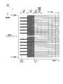
- FIG. 4 is a diagram showing an example of the OFDMA information field part and data part of the OFDM frame 201 (referred to as OFDM frame 201-1 in the description of FIG. 4) according to an embodiment of the present invention.
- the OFDMA information field part includes predetermined information for each subcarrier.
- the predetermined information includes channel band width (channel width) information, destination terminal device identifier (destination ID) information, and MCS information.
- the OFDMA information field part may further include other information.
- the channel width represents the entire channel width of the OFDM frame 201-1.
- the base station apparatus 11 can notify the terminal apparatus 12 of the channel width, the designation of the destination ID, and the designation of the MCS from the information in the OFDMA information field part.
- the MCS of a subcarrier corresponds to the transmission rate of the subcarrier.
- the OFDMA information field portion may include only one or two pieces of information of the modulation scheme, the modulation rate, or the coding rate as MCS information.
- information that is not included in the OFDMA information field portion may be fixed, for example, or by other methods. You may be notified.
- the channel width of the OFDM frame 201-1 is 20 MHz, and 54 subcarriers are used. A predetermined number of subcarriers among the 54 subcarriers are used to communicate pilot signals for signal tracking.
- the number of subcarriers constituting an OFDM frame (here, OFDM frame 201-1) is determined for each channel width.
- the base station apparatus 11 and the terminal apparatus 12 store information indicating the correspondence between the channel width and the number of subcarriers in the respective storage units 22 and 42 and refer to them. Also good.
- the channel width information for example, information indicating the channel width value may be used, or information such as an identification code corresponding to the channel width value may be used.
- the identification code corresponding to 20 MHz is set to 0
- the identification code corresponding to 40 MHz is set to 1
- the identification code corresponding to 80 MHz is set to 2
- the identification code corresponding to 160 MHz is set to 3 as a specific example.
- information indicating the correspondence between the channel width value and the identification code is set and stored in advance in the storage units 22 and 42 of the base station apparatus 11 and the terminal apparatus 12, for example.
- 20 MHz is stored in the OFDMA information field portion as channel width information of the OFDM frame 201-1 for all subcarriers.
- information for identifying the terminal device 12 that is a destination (information such as 01, 02, 03 in the example of FIG. 4) is used as the destination ID information.
- the MCS index information shown in FIG. 2 is stored in the OFDMA information field section as MCS information for each subcarrier.
- the base station apparatus 11 generates and transmits an OFDM frame 201-1 in which these pieces of information are stored in the OFDMA information field portion.
- Terminal apparatus 12 receives OFDM frame 201-1 and analyzes the OFDMA information field part of received OFDM frame 201-1 for each subcarrier for all subcarriers. Then, the terminal device 12 detects the destination ID information stored in the OFDMA information field section. In the terminal device 12, when information of a plurality of different destination IDs is included as a destination ID for each subcarrier in one OFDM frame 201-1, data communication multiplexing by OFDMA is performed based on the information. It is determined that The terminal device 12 identifies the information of the detected destination ID for each subcarrier, and stores the information of the destination ID corresponding to the information of the destination ID of the own device (the terminal device 12). Is identified.
- the number of specified subcarriers is the number of subcarriers addressed to the terminal apparatus 12 for transmitting data from the base station apparatus 11, and is, for example, one or more. When there is no data transmission from base station apparatus 11 to the own apparatus, the number of specified subcarriers is zero.
- the order in which data is stored (arranged) is determined. It has been. According to this order, the base station apparatus 11 stores data in the data part. In accordance with this order, the terminal device 12 obtains the data string by obtaining the data from the data part and combining the data. This order information is set and stored in advance in the storage units 22 and 42 of the base station apparatus 11 and the terminal apparatus 12, for example. In this way, the terminal device 12 can grasp the position where data is extracted from the OFDM frame 201-1.
- FIG. 4 shows an example of a data block (data block for each destination) assigned to each terminal apparatus 12 of each destination and a data string reading direction (data order).
- Each terminal device 12 can acquire data strings by combining data addressed to itself by reading data addressed to itself (the terminal device 12) in a predetermined direction.
- MCS modulation scheme, modulation rate, coding rate
- the part it is possible to modulate the part.
- MCS modulation scheme, modulation rate, coding rate
- the same MCS is set for two or more subcarriers to which the same destination is specified.
- FIG. 5 is a diagram showing another example of the OFDMA information field part and the data part of the OFDM frame 201 (referred to as the OFDM frame 201-2 in the description of FIG. 5) according to an embodiment of the present invention.
- the configuration of each field part and data part of the OFDM frame 201-2 according to the example of FIG. 5 is the same as that of the OFDM frame 201-1 according to the example of FIG.
- FIG. 5 illustrates, as an example, one terminal device 12 (terminal device 12 whose destination ID information is 01), a data block (data block for destination) assigned to the destination terminal device 12, and a data string The reading direction (data order) is shown.
- a pilot is allocated to some of the plurality of subcarriers constituting the OFDM frame 201 and is not used for data communication. However, in order to simplify the description, detailed description of the pilot is omitted here. To do.
- the base station apparatus 11 performs wireless communication by the OFDMA method by the function of a wireless LAN transmitter. This will be specifically described.
- the MCS control unit 31 designates the MCS for the serial-to-parallel conversion unit 32 and the subcarrier modulation unit 33 so that the determined MCS is used for each destination terminal device 12.
- the MCS may be fixedly determined for the destination terminal device 12 or may be variably determined by the MCS control unit 31 or the like.
- the serial / parallel converter 32 receives the transmission data.
- the transmission data includes a data packet addressed to each terminal device 12 for one or more terminal devices 12 accommodated in the base station device 11.
- the serial / parallel conversion unit 32 includes a plurality of buffer memories therein, and thereby holds data packets addressed to the plurality of terminal devices 12.
- the control unit 21 determines the data based on the length L [i] (bits) of the data packet and the MCS [i] specified and used.
- the number Ns [i] of OFDM symbols necessary for communicating the packet is calculated by Equation (1).
- Ns [i] roundup (L [i] ⁇ R / MOD) (1)
- Equation (1) MOD represents a modulation rate
- R represents a coding rate
- roundup (x) represents an operation for rounding up x to an integer value.
- the control unit 21 transmits a data string addressed to the i-th destination terminal device 12 based on the calculated number Ns [i] of OFDM symbols and the total number SCtotal of available subcarriers.
- the number of subcarriers SC [i] to be used for calculation is calculated and determined.
- various methods may be used as a method for determining the number of subcarriers SC [i]
- the serial / parallel conversion unit 32 parallelizes the data string of the addressed data packet for each destination terminal device 12 to the number of subcarriers SC [i] determined by the control unit 21. Then, the serial / parallel conversion unit 32 outputs the parallelized data string to the subcarrier modulation unit 33. At this time, the control unit 21 adds the bit sequence of the L-SIG unit and the bit sequence of the OFDMA information field unit to the head of the data sequence to be output for each subcarrier in the serial / parallel conversion unit 32.
- the subcarrier modulation unit 33 receives the data string output from the serial / parallel conversion unit 32. For each subcarrier, the subcarrier modulation unit 33 uses the designated MCS (modulation method, modulation rate, and coding rate) for the data of the received data string to perform modulation processing (in this embodiment, , Including encoding processing). The subcarrier modulation unit 33 outputs the data string obtained by the modulation process to the IFFT unit 34.
- MCS modulation method, modulation rate, and coding rate
- the IFFT unit 34 receives the data string output from the subcarrier modulation unit 33.
- the data string is a frequency-axis data string generated by the subcarrier modulation unit 33.
- the IFFT unit 34 performs IFFT processing on the received frequency-axis data string for a plurality of subcarriers, thereby converting the frequency-axis data string into a time-axis data string.
- the IFFT unit 34 outputs the converted time axis data string to the GI insertion unit 35.
- the GI insertion unit 35 receives the data string output from the IFFT unit 34.
- the GI insertion unit 35 inserts a guard interval into the received data string.
- the guard interval is an interval for preventing intersymbol interference in OFDM.
- the GI insertion unit 35 outputs the data string in which the guard interval is inserted to the D / A conversion unit 36.
- the D / A conversion unit 36 receives the data string output from the GI insertion unit 35. This data string is a digital data string.
- the D / A conversion unit 36 converts the received data string (digital signal) into an analog signal, and adds analog signals corresponding to the L-STF unit and the L-LTF unit to the head.
- the D / A converter 36 outputs the analog signal obtained thereby to the RF unit 37.
- the RF unit 37 receives the analog signal output from the D / A conversion unit 36.
- the RF unit 37 converts (up-converts) the frequency band of the received analog signal into a frequency band used for transmission, and outputs the converted analog signal to the antenna 38.
- the analog signal is transmitted (wireless transmission) from the antenna 38 as an OFDM wave.
- the functions of the IFFT unit 34, the GI insertion unit 35, the D / A conversion unit 36, the RF unit 37, and the antenna 38 for example, the same functions as existing functions that are generally used are used. May be.
- the terminal device 12 performs wireless communication by the OFDMA method by the function of the wireless LAN receiver. This will be specifically described.
- the antenna 51 receives a radio signal. In the present embodiment, the antenna 51 receives the OFDM wave transmitted from the base station apparatus 11.
- the RF unit 52 receives the OFDM wave received by the antenna 51.
- the RF unit 52 converts (down-converts) the frequency band of the received OFDM wave (analog signal) into a baseband frequency band, and outputs the converted analog signal to the A / D conversion unit 53 To do.
- the A / D converter 53 receives the analog signal output from the RF unit 52.
- the A / D conversion unit 53 detects the signals of the L-STF unit and the L-LTF unit included in the received analog signal, and synchronizes the timing of the analog signal based on the signal. Then, the A / D conversion unit 53 converts the analog signal into a digital signal (data string) in synchronization with the timing.
- the A / D conversion unit 53 outputs the data string obtained thereby to the GI removal unit 54.
- the GI removal unit 54 receives the data string output from the A / D conversion unit 53.
- the GI removal unit 54 removes the guard interval from the received data string.
- the GI removal unit 54 outputs the data string from which the guard interval has been removed to the FFT unit 55.
- the FFT unit 55 receives the data string output from the GI removal unit 54. This data string is time-axis data. The FFT unit 55 performs FFT processing on the received time-axis data string to convert the time-axis data string into a frequency-axis data string. The FFT unit 55 outputs the converted data string on the frequency axis to the subcarrier demodulation unit 56.
- the data string is a data string after the L-SIG part.
- the subcarrier demodulation unit 56 receives the data string output from the FFT unit 55.
- the data string is a parallel bit string arranged on the frequency axis.
- an L-SIG part and an OFDMA information field part exist at the head of the data string.
- the control unit 41 reads channel width information included in the OFDMA field portion from the data string of one or more subcarriers.
- the control unit 41 reads and identifies the destination ID information included in the OFDMA field portion from the data string for all subcarriers included in the channel width corresponding to the read channel width information.
- the control unit 41 Based on the result of identifying the destination ID information for all subcarriers, the control unit 41 includes destination ID information corresponding to (for example, matching) the destination ID information of the own device (terminal device 12). A subcarrier (that is, a subcarrier addressed to the own device) is selected. In addition, the control unit 41 reads MCS information included in the OFDMA information field unit for the selected subcarrier, and identifies the MCS. The subcarrier demodulator 56 determines in advance the data included in the data part of the subcarrier selected by the control unit 41 (for example, one or more subcarriers when there is a subcarrier addressed to the own device). The data string is obtained by reading (extracting) in the same order.
- the subcarrier demodulating unit 56 uses the MCS (modulation method, modulation rate, and coding rate) specified by the control unit 41 to perform demodulation processing (in this embodiment, data string destined for the own device). Including decryption processing).
- the subcarrier demodulation unit 56 outputs the data string obtained by the demodulation process to the parallel / serial conversion unit 57.
- the parallel / serial converter 57 serializes the data string output from the subcarrier demodulator 56. As a result, the original data (packet data to be transmitted from the base station apparatus 11) is restored. The data is obtained as received data.
- the destination ID information in the OFDMA information field part for example, 48-bit MAC address information may be used, or when the base station apparatus 11 and the terminal apparatus 12 are connected, the base station 11-bit AID (Association ID) information assigned by the device 11 to the terminal device 12 may be used.
- the base station apparatus 11 stores information on the destination ID of each terminal apparatus 12 managed and connected by the own apparatus (the base station apparatus 11) in the storage unit 22.
- Each terminal device 12 stores information on the destination ID of its own device (the terminal device 12) in the storage unit 42.
- shortened destination ID information As another configuration example, by using part of bit information (shortened destination ID information) of the destination ID of the terminal device 12 as destination ID information of the OFDMA information field portion, It is possible to shorten the number of bits. For example, a predetermined number of bits lower than the original destination ID (non-shortened destination ID) may be used as the partial bits.
- the base station device 11 and each terminal device 12 may store the information of the original destination ID and acquire (for example, calculate) the information of the shortened destination ID based on the information, or shorten the information. Information on the destination ID may be stored in each of the storage units 22 and 42.
- a case will be described in which information on a part of bits of the AID of the terminal device 12 (shortened AID information) is used as destination ID information in the OFDMA information field portion.
- shortened AID information information on a part of bits of the AID of the terminal device 12
- a plurality of terminal devices 12 compete with each other with the same shortened AID.
- a configuration that reduces or prevents such competition may be used.
- the control unit 21 sends data having two or more different terminal apparatuses 12 having a destination ID that is the same shortened AID to the same OFDM frame 201 to be transmitted. Control so as not to overlap.
- the control unit 21 superimposes data having a destination ID that is the same shortened AID but destined for two or more different terminal apparatuses 12 on the same OFDM frame 201 to be transmitted. May be.
- the information of the same shortened AID included in the OFDMA information field part is identified as the information of the destination ID addressed to the own device. Since the MCSs are different, in each terminal apparatus 12, the control unit 41 can identify that the data addressed to the other terminal apparatus 12 exists in the OFDM frame 201 by a combination of the shortened AID and the MCS. Is possible.
- the control unit 41 acquires (restores) a MAC frame from the decrypted data sequence, and obtains the destination MAC address described in the MAC frame and the MAC address of the own device. By collating, it is possible to select and acquire data destined for the own device whose MAC addresses match. On the other hand, in each terminal device 12, the control unit 41 can discard data addressed to other devices whose MAC addresses do not match. As described above, the control unit 41 may perform a process of determining whether or not to select data of each subcarrier based on the result of restoring the received data string (here, the MAC address). . Similar processing may be performed using information of an address other than the MAC address.
- the control unit 21 may include reservation time information in the L-SIG part of the OFDM frame 201.
- the control unit 41 reads out and acquires information on the reservation time included in the L-SIG part of the received OFDM frame 201, and performs control so that wireless communication is not performed during the reservation time.
- the control unit 21 reads information on the reservation time included in the L-SIG unit of the received OFDM frame 201. Obtain and control not to perform wireless communication during the reservation time.
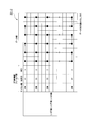
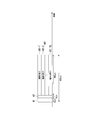
- FIG. 6 is a diagram illustrating an example of the time required for data communication according to an embodiment of the present invention.
- FIG. 7 is a diagram illustrating an example of the time required for data communication according to the comparative example.
- data communication according to the comparative example will be described with reference to FIG.
- data communication in which a base station apparatus transmits a data packet having a size of 100 bytes to each of 10 terminal apparatuses is referred to as data communication according to a comparative example.
- ten terminal devices are referred to as terminal 1 to terminal 10.
- FIG. 7 shows an image of data communication with the horizontal axis as time.
- the base station apparatus transmits frames including data packets to the terminals 1 to 10 in the order of the terminals 1 to 10.
- Each frame includes predetermined field parts B11-1 to B11-10 and data parts B12-1 to B12-10.
- Predetermined field portions B11-1 to B11-10 include an L-STF portion, an L-LTF portion, and an L-SIG portion.
- a wireless LAN similar to the prior art is assumed.
- the communication (transmission) of the predetermined field parts B11-1 to B11-10 takes 20 ⁇ s.
- the frame interval (DIFS: Distributed Control Function Inter-Frame Space) is at least 34 ⁇ s, and it is assumed here that the time is 34 ⁇ s.
- random waiting time between frames which is necessary in a normal wireless LAN communication procedure, or transmission of an ACK frame that is a reception confirmation response transmitted from a terminal device is used. The time required is not considered.
- the base station apparatus 11 performs data communication for transmitting a data packet having a size of 100 bytes to each of the ten terminal apparatuses 12 simultaneously in one frame.
- ten terminal devices 12 are referred to as terminal 1 to terminal 10.
- FIG. 6 shows an image of data communication with the horizontal axis as time.
- the base station apparatus 11 transmits one frame (in this embodiment, an OFDM frame 201) including a data packet addressed to each of the ten terminals 1 to 10.
- the frame includes a predetermined field part A1, an OFDMA information field part A2, and a data part A11 in which data parts A11-1 to A11-10 addressed to ten terminals 1 to 10 are multiplexed.
- Predetermined field portion A1 includes an L-STF portion, an L-LTF portion, and an L-SIG portion.
- the communication (transmission) of the predetermined field portion A1 requires 20 ⁇ s. Further, it is assumed that the communication (transmission) of the OFDMA information field part A2 requires 8 ⁇ s. In the example of FIG. 3, the time is 4 ⁇ s, but here it is assumed to be a little longer for comparison.
- the base station apparatus 11 multiplexes data to 10 terminals 1 to 10 by OFDMA and transmits the data simultaneously, the transmission rate per terminal becomes 1/10.
- 1 Mbps which is / 10.
- 100 bytes of data are modulated and transmitted at 1 Mbps
- the base station apparatus 11 when the base station apparatus 11 and the terminal apparatus 12 perform wireless communication using the wireless LAN method, the base station apparatus 11 includes a plurality of OFDM frames 201 in one OFDM frame 201.
- the data for the terminal device 12 can be multiplexed and transmitted.
- the terminal device 12 can extract and restore data addressed to itself from among a plurality of data addressed to the terminal device 12 multiplexed in one received OFDM frame 201.
- improvement in transmission efficiency can be realized. it can.
- the case where data is transmitted from the base station apparatus 11 to the plurality of terminal apparatuses 12 using communication combining a wireless LAN and OFDMA is shown as an example.
- a similar configuration may be applied to the cellular communication or WiMAX scheme.
- cellular communication for example, LTE communication
- WiMAX the same configuration as that of the present embodiment is applied to the base station apparatus and the terminal apparatus in a communication system that transmits data from the base station apparatus to a plurality of terminal apparatuses using OFDMA.
- one or both of the base station device and the terminal device can perform cellular communication, wireless LAN system, or WiMAX two types of communication simultaneously (for example, a transmitter function or a receiver function). Function).
- a configuration capable of performing two types of communication simultaneously for example, a configuration having both of two types of communication functions may be used.
- the serial-parallel conversion unit, the RF unit, and the like having these configurations can be shared, and a communication device can be efficiently configured.
- the base station apparatus 11 includes a data string for each subcarrier including information on a destination (destination ID in the present embodiment) and data addressed to the destination (data in the data section in the present embodiment). Includes a transmitter 23 that wirelessly transmits a frame multiplexed with OFDM for a plurality of subcarriers (OFDM frame 201 in the present embodiment).
- the data string for each subcarrier includes one or more pieces of information (in this embodiment, MCS information) of the modulation scheme, modulation rate, or encoding rate. .
- the data string for each subcarrier includes all information on the modulation scheme, modulation rate, and encoding rate (information on MCS in the present embodiment) for the data.
- the data string for each subcarrier includes information on the channel width of the entire frame.
- the data string for each subcarrier includes time information for reserving the time required for data communication.
- identification information in the present embodiment, the terminal apparatus 12 in the present embodiment
- the destination ID in the present embodiment, the destination ID
- a part of the information (information identifying the destination) (in this embodiment, information on the shortened destination ID) is used.
- the transmission unit 23 simultaneously performs cellular communication, a wireless LAN method, or two types of WiMAX communication (any two types of these three methods). Is possible.
- the terminal device 12 receives a frame in which a data sequence for each subcarrier including destination information and data addressed to the destination is multiplexed by OFDM for a plurality of subcarriers; Based on the destination information included for each subcarrier constituting the frame received by the receiving unit 43, the control unit 41 selects a subcarrier including destination information corresponding to the information of the own device (the terminal device 12). And comprising.
- the terminal device 12 a part of the identification information set in the destination device (the terminal device 12 in the present embodiment) as the information on the destination (the destination ID in the present embodiment).
- control unit 41 is based on the result of restoring the data of the subcarrier including the destination information corresponding to a part of the identification information set in the own device (the terminal device 12). To determine whether to select the data.
- the receiving unit 43 can simultaneously perform cellular communication, a wireless LAN method, or two types of WiMAX communication (any two types of these three methods). Is possible.
- the base station apparatus 11 wirelessly transmits a frame in which a data string for each subcarrier including destination information and data addressed to the destination is multiplexed by OFDM for a plurality of subcarriers.
- the terminal device 12 transmits a subcarrier including destination information corresponding to the information of the own device (the terminal device 12) based on the destination information included in each subcarrier constituting the received frame. select.
- the base station apparatus 11 wirelessly transmits a frame in which a data sequence for each subcarrier including destination information and data addressed to the destination is multiplexed by OFDM for a plurality of subcarriers. Send.
- a program for realizing the function of each device is recorded (stored) in a computer-readable recording medium (storage medium).
- the processing may be performed by causing the computer system to read and execute the program recorded on the recording medium.
- the “computer system” may include hardware such as an operating system (OS) and peripheral devices.
- the “computer-readable recording medium” means a flexible disk, a magneto-optical disk, a ROM (Read Only Memory), a writable nonvolatile memory such as a flash memory, a portable medium such as a DVD (Digital Versatile Disk), A storage device such as a hard disk built in a computer system.
- the “computer-readable recording medium” refers to a volatile memory (for example, DRAM (DRAM) inside a computer system that becomes a server or a client when a program is transmitted through a network such as the Internet or a communication line such as a telephone line. Dynamic Random Access Memory)), etc., which hold programs for a certain period of time.
- the program may be transmitted from a computer system storing the program in a storage device or the like to another computer system via a transmission medium or by a transmission wave in the transmission medium.
- the “transmission medium” for transmitting the program refers to a medium having a function of transmitting information, such as a network (communication network) such as the Internet or a communication line (communication line) such as a telephone line.
- the above program may be for realizing a part of the functions described above.
- the above program may be a so-called difference file (difference program) that can realize the above-described functions in combination with a program already recorded in the computer system.
Landscapes
- Engineering & Computer Science (AREA)
- Computer Networks & Wireless Communication (AREA)
- Signal Processing (AREA)
- Mobile Radio Communication Systems (AREA)
Abstract
無線LAN等とOFDMAを組み合わせた通信を用いて、基地局装置から複数の端末装置に対してデータを伝送する場合に、基地局装置は、宛先の情報および当該宛先に宛てられたデータを含むサブキャリアごとのデータ列が複数のサブキャリアについてOFDMにより多重化されたフレームを無線により送信する送信部を備える。
Description
本発明は、基地局装置、端末装置、通信システムおよび通信方法に関する。
本願は、2015年3月5日に、日本に出願された特願2015-43215号に基づき優先権を主張し、その内容をここに援用する。
本願は、2015年3月5日に、日本に出願された特願2015-43215号に基づき優先権を主張し、その内容をここに援用する。
携帯電話端末に代表されるユーザ端末がデータ通信を移動しながら行う技術(移動無線データ通信の技術)の進歩は目覚ましく、様々な無線通信方式の技術革新がなされ実用化されている。近年では、直交周波数分割多元アクセス(OFDMA:Orthogonal Frequency Division Multiple Access)の技術を用いたLTE(Long Term Evolution)方式あるいはWiMAX(Worldwide Interoperability for Microwave Access)方式といった第4世代のデータ通信を高速化した通信規格が主流となっている。OFDMAでは、直交周波数分割多重方式(OFDM:Orthogonal Frequency Division Multiplexing)によって複数の端末装置のアクセスを可能としている。
一方、パーソナルコンピュータ(PC:Personal Computer)などを中心に搭載されてきた無線LAN(Local Area Network)の通信方式は、CSMA/CA(Carrier Sense Multiple Access with Collision Avoidance)方式を用いた基地局装置との通信手順を基本として発展してきている。そして、無線LANの通信方式の規格を策定しているIEEE802.11作業委員会は、より高効率にデータ通信を行うことを実現するために、現状のCSMA/CAをベースとした無線LANの通信方式に対してOFDMAの技術を適用することを検討し始めている。
特許文献1には、WiMAXにおける無線通信の方法が記載されている(特許文献1参照。)。特許文献1の図4Aには、フレーム構成が示されている。基地局装置から端末装置への方向にデータを伝送するためのダウンリンクサブフレームは、プリアンブルと、フレーム制御ヘッダ(FCH)と、DL-MAPと、UL-MAPと、複数のデータバーストを含む。プリアンブルは、フレームの同期に使用される。FCHは、DL-MAPの復号化方法を示す。DL-MAPは、ダウンリンクサブフレームにおけるそれぞれの端末装置宛てのデータバースト領域の復号化位置および復号化方法を示す。UL-MAPは、それぞれの端末装置が基地局装置宛てにデータを伝送する際に使用するアップリンクサブフレームにおけるデータバースト領域の位置等を指定する。それぞれのデータバーストは、それぞれの端末装置宛てに伝送するデータ本体を格納する。
ここで、特許文献1に記載された無線通信の方法では、DL-MAPによってそれぞれの端末装置宛てに伝送するデータの位置を示すことにより、基地局装置から端末装置への方向にデータを伝送する際に複数の端末装置宛てのデータを多重することを実現している。これにより、OFDMAを用いた多元アクセスを実現している。DL-MAPは、DL-MAPメッセージと呼ばれるMAC(Media Access Control)マネジメントメッセージから構成される。DL-MAPには、それぞれのデータバーストに関するバースト割り当て情報が含まれる。バースト割り当て情報は、OFDMAフレームにおけるデータの位置を示す情報である。
しかしながら、特許文献1に記載された無線通信の方法では、次のような問題があった。
すなわち、WiMAXにおけるDL-MAPはMACフレームを用いて実現される。一方、データバーストの位置を把握するためには、MACフレームを解析するより前におけるOFDMAフレームのOFDMシンボルの位置を識別する必要がある。このため、この無線通信の方法を無線LAN(Local Area Network)に適用する場合には、所望のデータ列を取り出す際に、PHY(Physical)層の処理とMAC層の処理を行き来して行う必要があり、非効率的であった。具体的には、この無線通信の方法では、MACフレームであるDL-MAPを解析してデータバーストの位置情報を得て、これにより得られた位置情報に基づいてPHY層の解析位置を判定し、指定の手順によりデータを抜き出すことによって、MACフレーム形式の所望のデータ列を取り出す。
すなわち、WiMAXにおけるDL-MAPはMACフレームを用いて実現される。一方、データバーストの位置を把握するためには、MACフレームを解析するより前におけるOFDMAフレームのOFDMシンボルの位置を識別する必要がある。このため、この無線通信の方法を無線LAN(Local Area Network)に適用する場合には、所望のデータ列を取り出す際に、PHY(Physical)層の処理とMAC層の処理を行き来して行う必要があり、非効率的であった。具体的には、この無線通信の方法では、MACフレームであるDL-MAPを解析してデータバーストの位置情報を得て、これにより得られた位置情報に基づいてPHY層の解析位置を判定し、指定の手順によりデータを抜き出すことによって、MACフレーム形式の所望のデータ列を取り出す。
上述のように、従来では、無線LANとOFDMAを組み合わせた通信を用いて、基地局装置から複数の端末装置に対してデータを伝送する場合に、通信効率に不十分な点があった。
本発明は、このような事情を考慮してなされたもので、無線LAN等とOFDMAを組み合わせた通信を用いて、基地局装置から複数の端末装置に対してデータを伝送する場合に、伝送効率の向上を実現することができる基地局装置、端末装置、通信システムおよび通信方法を提供することを課題とする。
上記の課題を解決するために、一態様に係る基地局装置は、宛先の情報および当該宛先に宛てられたデータを含むサブキャリアごとのデータ列が複数のサブキャリアについてOFDMにより多重化されたフレームを無線により送信する送信部を備える。
一態様として、基地局装置では、前記サブキャリアごとのデータ列は、前記データについて、変調方式、変調レートまたは符号化レートのうちの1以上の情報を含む構成が用いられてもよい。
一態様として、基地局装置では、前記サブキャリアごとのデータ列は、前記データについて、変調方式、変調レートおよび符号化レートのすべての情報を含む構成が用いられてもよい。
一態様として、基地局装置では、前記サブキャリアごとのデータ列は、前記フレーム全体のチャネル幅の情報を含む構成が用いられてもよい。
一態様として、基地局装置では、前記サブキャリアごとのデータ列は、データ通信に必要な時間を予約するための時間の情報を含む構成が用いられてもよい。
一態様として、基地局装置では、前記宛先の情報として、前記宛先の装置に設定される識別情報のうちの一部の情報が用いられる構成が用いられてもよい。
一態様として、基地局装置では、前記送信部は、セルラー通信、無線LANの方式、もしくはWiMAXの内の二種類の通信を同時に行うことが可能である構成が用いられてもよい。
一態様として、基地局装置では、前記サブキャリアごとのデータ列は、前記データについて、変調方式、変調レートまたは符号化レートのうちの1以上の情報を含む構成が用いられてもよい。
一態様として、基地局装置では、前記サブキャリアごとのデータ列は、前記データについて、変調方式、変調レートおよび符号化レートのすべての情報を含む構成が用いられてもよい。
一態様として、基地局装置では、前記サブキャリアごとのデータ列は、前記フレーム全体のチャネル幅の情報を含む構成が用いられてもよい。
一態様として、基地局装置では、前記サブキャリアごとのデータ列は、データ通信に必要な時間を予約するための時間の情報を含む構成が用いられてもよい。
一態様として、基地局装置では、前記宛先の情報として、前記宛先の装置に設定される識別情報のうちの一部の情報が用いられる構成が用いられてもよい。
一態様として、基地局装置では、前記送信部は、セルラー通信、無線LANの方式、もしくはWiMAXの内の二種類の通信を同時に行うことが可能である構成が用いられてもよい。
上記の課題を解決するために、一態様に係る端末装置は、宛先の情報および当該宛先に宛てられたデータを含むサブキャリアごとのデータ列が複数のサブキャリアについてOFDMにより多重化されたフレームを受信する受信部と、前記受信部により受信された前記フレームを構成する前記サブキャリアごとに含まれる前記宛先の情報に基づいて、自装置の情報に対応する前記宛先の情報を含む前記サブキャリアを選択する制御部とを備える。
一態様として、端末装置では、前記宛先の情報として、前記宛先の装置に設定される識別情報のうちの一部の情報が用いられ、前記制御部は、自装置に設定される識別情報のうちの一部に対応する前記宛先の情報を含む前記サブキャリアの前記データについて、当該データを復元した結果に基づいて当該データを選択するか否かを判定する構成が用いられてもよい。
一態様として、端末装置では、前記受信部は、セルラー通信、無線LANの方式、もしくはWiMAXの内の二種類の通信を同時に行うことが可能である構成が用いられてもよい。
一態様として、端末装置では、前記宛先の情報として、前記宛先の装置に設定される識別情報のうちの一部の情報が用いられ、前記制御部は、自装置に設定される識別情報のうちの一部に対応する前記宛先の情報を含む前記サブキャリアの前記データについて、当該データを復元した結果に基づいて当該データを選択するか否かを判定する構成が用いられてもよい。
一態様として、端末装置では、前記受信部は、セルラー通信、無線LANの方式、もしくはWiMAXの内の二種類の通信を同時に行うことが可能である構成が用いられてもよい。
上記の課題を解決するために、一態様に係る通信システムでは、基地局装置は、宛先の情報および当該宛先に宛てられたデータを含むサブキャリアごとのデータ列が複数のサブキャリアについてOFDMにより多重化されたフレームを無線により送信し、端末装置は、受信された前記フレームを構成する前記サブキャリアごとに含まれる前記宛先の情報に基づいて、自装置の情報に対応する前記宛先の情報を含む前記サブキャリアを選択する。
上記の課題を解決するために、一態様に係る通信方法では、基地局装置は、宛先の情報および当該宛先に宛てられたデータを含むサブキャリアごとのデータ列が複数のサブキャリアについてOFDMにより多重化されたフレームを無線により送信する。
上記の課題を解決するために、一態様に係る通信方法では、基地局装置は、宛先の情報および当該宛先に宛てられたデータを含むサブキャリアごとのデータ列が複数のサブキャリアについてOFDMにより多重化されたフレームを無線により送信する。
本発明によれば、無線LAN等とOFDMAを組み合わせた通信を用いて、基地局装置から複数の端末装置に対してデータを伝送する場合に、伝送効率の向上を実現することができる。
以下、図面を参照し、本発明の実施形態について説明する。
図1は、本発明の一実施形態に係る通信システム1の概略的な構成を示すブロック図である。
通信システム1は、無線LANとOFDMAを組み合わせた通信を行う基地局装置11および端末装置12を備える。基地局装置11は、無線LANのアクセスポイント(AP:Access Point)となる装置(無線通信装置)である。端末装置12は、基地局装置11により管理されて、当該基地局装置11と通信する装置(無線通信装置)である。通信システム1は、複数の端末装置12を備える。また、通信システム1は、複数の基地局装置11を備えてもよい。
図1は、本発明の一実施形態に係る通信システム1の概略的な構成を示すブロック図である。
通信システム1は、無線LANとOFDMAを組み合わせた通信を行う基地局装置11および端末装置12を備える。基地局装置11は、無線LANのアクセスポイント(AP:Access Point)となる装置(無線通信装置)である。端末装置12は、基地局装置11により管理されて、当該基地局装置11と通信する装置(無線通信装置)である。通信システム1は、複数の端末装置12を備える。また、通信システム1は、複数の基地局装置11を備えてもよい。
本実施形態では、主に、基地局装置11に備えられる無線LANの送信機の機能、および、端末装置12に備えられる無線LANの受信機の機能を説明する。基地局装置11および端末装置12は、それぞれ、無線LANの送信機の機能および受信機の機能の両方を備えてもよく、本実施形態では、両方を備える。
基地局装置11は、制御部21と、記憶部22と、送信部23を備える。送信部23は、MCS(Modulation and Coding Scheme)制御部31と、直列並列変換部32と、サブキャリア変調部33と、逆高速フーリエ変換(IFFT:Inverse Fast Fourier Transform)部34と、ガードインターバル(GI:Guard Interval)挿入部35と、デジタル/アナログ(D/A:Digital to Analog)変換部36と、無線周波数(RF:Radio Frequency)部37と、アンテナ38とを備える。
本実施形態では、送信部23が送信機の機能を有する。また、制御部21が、送信部23を含めて基地局装置11における各種の制御を行う。なお、本実施形態に係る基地局装置11の構成は一例であり、他の構成が用いられてもよい。例えば、他の構成例として、MCS制御部31の機能が制御部21に含まれてもよい。
本実施形態では、送信部23が送信機の機能を有する。また、制御部21が、送信部23を含めて基地局装置11における各種の制御を行う。なお、本実施形態に係る基地局装置11の構成は一例であり、他の構成が用いられてもよい。例えば、他の構成例として、MCS制御部31の機能が制御部21に含まれてもよい。
端末装置12は、制御部41と、記憶部42と、受信部43を備える。受信部43は、アンテナ51と、RF部52と、アナログ/デジタル(A/D:Analog to Digital)変換部53と、GI除去部54と、高速フーリエ変換(FFT:Fast Fourier Transform)部55と、サブキャリア復調部56と、並列直列変換部57を備える。
本実施形態では、受信部43が受信機の機能を有する。また、制御部41が、受信部43を含めて端末装置12における各種の制御を行う。なお、本実施形態に係る端末装置12の構成は一例であり、他の構成が用いられてもよい。
本実施形態では、受信部43が受信機の機能を有する。また、制御部41が、受信部43を含めて端末装置12における各種の制御を行う。なお、本実施形態に係る端末装置12の構成は一例であり、他の構成が用いられてもよい。
図2は、本発明の一実施形態に係るMCSテーブル101の一例を示す図である。
MCSテーブル101は、変調方法および符号化方法を示すMCSの情報を格納するテーブルの一例である。なお、復調方法は変調方法に対応して決定されることが可能であり、復号化方法は符号化方法に対応して決定されることが可能である。
本実施形態では、MCSテーブル101は、インデックス(本実施形態では、MCSインデックスと呼ぶ。)と、変調方式と、変調レート(MOD)と、符号化レート(R)とを対応付けて格納する。
MCSインデックスとしては、0、1、2、・・・といった連続した番号が用いられている。
変調方式としては、BPSK(Binary Phase Shift Keying)、QPSK(Quadrature Phase Shift Keying)、16QAM(Quadrature Amplitude Modulation)、64QAM、256QAMなどの変調方式が用いられている。
変調レートとしては、1、2、4、6、8などの値が用いられている。
符号化レートとしては、1/2、3/4、2/3、5/6などの値が用いられている。
MCSテーブル101は、変調方法および符号化方法を示すMCSの情報を格納するテーブルの一例である。なお、復調方法は変調方法に対応して決定されることが可能であり、復号化方法は符号化方法に対応して決定されることが可能である。
本実施形態では、MCSテーブル101は、インデックス(本実施形態では、MCSインデックスと呼ぶ。)と、変調方式と、変調レート(MOD)と、符号化レート(R)とを対応付けて格納する。
MCSインデックスとしては、0、1、2、・・・といった連続した番号が用いられている。
変調方式としては、BPSK(Binary Phase Shift Keying)、QPSK(Quadrature Phase Shift Keying)、16QAM(Quadrature Amplitude Modulation)、64QAM、256QAMなどの変調方式が用いられている。
変調レートとしては、1、2、4、6、8などの値が用いられている。
符号化レートとしては、1/2、3/4、2/3、5/6などの値が用いられている。
本実施形態では、MCSテーブル101に相当する情報が、基地局装置11の記憶部22および端末装置12の記憶部42のそれぞれに記憶されている。
ここで、説明の便宜上、基地局装置11に記憶されるMCSテーブル101をMCSテーブル101-1と呼び、端末装置12に記憶されるMCSテーブル101をMCSテーブル101-2と呼ぶ。MCSテーブル101-1の情報とMCSテーブル101-2の情報とは、例えば、同じであってもよく、または、互いに対応していれば、完全に同じでなくてもよい。
ここで、説明の便宜上、基地局装置11に記憶されるMCSテーブル101をMCSテーブル101-1と呼び、端末装置12に記憶されるMCSテーブル101をMCSテーブル101-2と呼ぶ。MCSテーブル101-1の情報とMCSテーブル101-2の情報とは、例えば、同じであってもよく、または、互いに対応していれば、完全に同じでなくてもよい。
図3は、本発明の一実施形態に係るOFDMフレーム201の一例を示す図である。
図3では、縦軸は周波数(周波数軸)を表しており、横軸は時間(時間軸)を表している。周波数方向は、複数のサブキャリアの並びの方向となる。時間方向は、複数のシンボル(ビット列)の並びの方向となる。
本実施形態に係るOFDMフレーム201は、IEEE802.11nの方式に基づく一例である。
OFDMフレーム201は、20MHzの帯域を用いてフレームを送信する場合の例である。
また、OFDMフレーム201は、64ポイント(64波)のFFTを用いて変調されたフレームである。そして、OFDMフレーム201は、64波のうちの54波のサブキャリアで構成される。64波のうちの残りの10波は、隣接チャネルとの干渉を避けるために使用されない。図3の例では、中心周波数を基準として-8.125MHz~+8.125MHzの範囲で54波のサブキャリアが用いられる。複数のサブキャリアは、312.5kHzの間隔で配置されるが、互いに直交しているため周波数軸上で互いに重なり合うほど密に配置されているにも関わらず互いに干渉せずに復号化することができる。
なお、OFDM方式を用いた無線通信の原理については、例えば公知の原理が用いられてもよく、詳細な説明を省略する。
図3では、縦軸は周波数(周波数軸)を表しており、横軸は時間(時間軸)を表している。周波数方向は、複数のサブキャリアの並びの方向となる。時間方向は、複数のシンボル(ビット列)の並びの方向となる。
本実施形態に係るOFDMフレーム201は、IEEE802.11nの方式に基づく一例である。
OFDMフレーム201は、20MHzの帯域を用いてフレームを送信する場合の例である。
また、OFDMフレーム201は、64ポイント(64波)のFFTを用いて変調されたフレームである。そして、OFDMフレーム201は、64波のうちの54波のサブキャリアで構成される。64波のうちの残りの10波は、隣接チャネルとの干渉を避けるために使用されない。図3の例では、中心周波数を基準として-8.125MHz~+8.125MHzの範囲で54波のサブキャリアが用いられる。複数のサブキャリアは、312.5kHzの間隔で配置されるが、互いに直交しているため周波数軸上で互いに重なり合うほど密に配置されているにも関わらず互いに干渉せずに復号化することができる。
なお、OFDM方式を用いた無線通信の原理については、例えば公知の原理が用いられてもよく、詳細な説明を省略する。
OFDMフレーム201は、先頭から順に、L-STF(Non HT - Short Training Field)部と、L-LTF(Non HT - Long Training Field)部と、L-SIG(Non HT -Signal Field)部と、OFDMA情報フィールド部と、データ部を含む。なお、OFDMフレーム201は、さらに他のフィールド部を含んでもよい。また、本実施形態では、L-STF部、L-LTF部、L-SIG部、OFDMA情報フィールド部、データ部という名称を用いて説明するが、それぞれ、同様な情報を格納する部分が他の名称で呼ばれてもよい。
ここで、L-STF部、L-LTF部およびL-SIG部は、例えば、無線LANの既存の方式では必要なフィールド部である。
L-STF部およびL-LTF部は、無線LANの信号の検出と、信号へのタイミングの同期を行うために設けられている。本実施形態では、L-STF部およびL-LTF部には、無線LANの既存の方式と同様な情報が含められる。
L-STF部およびL-LTF部は、無線LANの信号の検出と、信号へのタイミングの同期を行うために設けられている。本実施形態では、L-STF部およびL-LTF部には、無線LANの既存の方式と同様な情報が含められる。
L-SIG部には、無線LANの既存の方式では、データ部を復号化するために必要な情報が含められる。例えば、無線LANの既存の方式で規定されるL-SIG部は、それぞれのサブキャリアのデータ部の変調レートとデータビット数(データ長)の情報を含むことによって、当該L-SIG部が含まれる無線フレームの時間長を示すことができる。
これに対して、本実施形態では、L-SIG部に、無線LANの既存の方式とは異なる情報が含められてもよい。一例として、本実施形態では、L-SIG部に、無線空間の利用を予約する時間(予約時間)を示す情報が含められてもよい。当該予約時間は、例えば、データ通信に必要な時間であり、OFDMフレーム201の通信にかかる時間である。
具体例として、当該予約時間として、基地局装置11がOFDMフレーム201を送信してから、当該OFDMフレーム201を受信した宛先の端末装置12から送信される信号(確認応答信号)を受信することが完了するまでの時間が用いられる。この場合、基地局装置11の通信相手ではない端末装置12では、受信されたOFDMフレーム201のL-SIG部に含まれる予約時間の情報に基づいて、当該予約時間に相当する時間では、無線区間を利用しない(無線信号を送信しない)ように制御する。
これに対して、本実施形態では、L-SIG部に、無線LANの既存の方式とは異なる情報が含められてもよい。一例として、本実施形態では、L-SIG部に、無線空間の利用を予約する時間(予約時間)を示す情報が含められてもよい。当該予約時間は、例えば、データ通信に必要な時間であり、OFDMフレーム201の通信にかかる時間である。
具体例として、当該予約時間として、基地局装置11がOFDMフレーム201を送信してから、当該OFDMフレーム201を受信した宛先の端末装置12から送信される信号(確認応答信号)を受信することが完了するまでの時間が用いられる。この場合、基地局装置11の通信相手ではない端末装置12では、受信されたOFDMフレーム201のL-SIG部に含まれる予約時間の情報に基づいて、当該予約時間に相当する時間では、無線区間を利用しない(無線信号を送信しない)ように制御する。
本実施形態では、無線LANの既存の方式に対応する無線通信装置(本実施形態に係る新規な方式には対応しない無線通信装置)によってもフレームを検知することが可能な構成で、OFDMフレーム201を構成している。つまり、本実施形態では、本実施形態に係る新規な方式に対応する無線通信装置(例えば、基地局装置11および端末装置12)であっても、あるいは、無線LANの既存の方式に対応する無線通信装置(本実施形態に係る新規な方式には対応しない無線通信装置)であっても、基地局装置11から送信されるOFDMフレーム201を検知することを可能としている。
これにより、無線LANを用いた通信システム(本実施形態に係る通信システム1および既存の通信システム)において、それぞれの無線通信装置が周囲の他の無線通信装置が通信していないときにのみ電波を送出する制御を行うことで、互いに無線信号の衝突を防ぐという仕組みを維持することができる。
これにより、無線LANを用いた通信システム(本実施形態に係る通信システム1および既存の通信システム)において、それぞれの無線通信装置が周囲の他の無線通信装置が通信していないときにのみ電波を送出する制御を行うことで、互いに無線信号の衝突を防ぐという仕組みを維持することができる。
また、OFDMA情報フィールド部は、無線LANの既存の方式では設けられないフィールド部であり、本実施形態において追加されている。本実施形態では、OFDMA情報フィールド部のビット列は、OFDMフレーム201を形成するサブキャリアごとのヘッダ部(本実施形態では、PHYヘッダ部)に設けられる。
なお、本実施形態では、54波のサブキャリアのうちで、所定の数(例えば、4個)のサブキャリアには、パイロットが割り当てられる。パイロットが割り当てられたサブキャリアは、データ通信には使用されず、OFDMA情報フィールド部を設けることは不要である。54波のサブキャリアのうちで、パイロットが割り当てられないサブキャリアが、データ通信に使用される。
なお、本実施形態では、54波のサブキャリアのうちで、所定の数(例えば、4個)のサブキャリアには、パイロットが割り当てられる。パイロットが割り当てられたサブキャリアは、データ通信には使用されず、OFDMA情報フィールド部を設けることは不要である。54波のサブキャリアのうちで、パイロットが割り当てられないサブキャリアが、データ通信に使用される。
図4は、本発明の一実施形態に係るOFDMフレーム201(図4の説明において、OFDMフレーム201-1と呼ぶ。)のOFDMA情報フィールド部およびデータ部の一例を示す図である。
図4では、L-STF部、L-LTF部およびL-SIG部については、詳細を省略してある。
OFDMA情報フィールド部は、それぞれのサブキャリアごとに、所定の情報を含む。
当該所定の情報は、チャネルの帯域の幅(チャネル幅)の情報と、宛先の端末装置を識別する識別子(宛先ID)の情報と、MCSの情報である。なお、OFDMA情報フィールド部は、さらに他の情報を含んでもよい。ここで、チャネル幅は、OFDMフレーム201-1の全体のチャネル幅を表す。
本実施形態では、基地局装置11から端末装置12に対して、OFDMA情報フィールド部の情報により、チャネル幅を通知し、宛先IDの指定を通知し、MCSの指定を通知することができる。
図4では、L-STF部、L-LTF部およびL-SIG部については、詳細を省略してある。
OFDMA情報フィールド部は、それぞれのサブキャリアごとに、所定の情報を含む。
当該所定の情報は、チャネルの帯域の幅(チャネル幅)の情報と、宛先の端末装置を識別する識別子(宛先ID)の情報と、MCSの情報である。なお、OFDMA情報フィールド部は、さらに他の情報を含んでもよい。ここで、チャネル幅は、OFDMフレーム201-1の全体のチャネル幅を表す。
本実施形態では、基地局装置11から端末装置12に対して、OFDMA情報フィールド部の情報により、チャネル幅を通知し、宛先IDの指定を通知し、MCSの指定を通知することができる。
なお、サブキャリアのMCSは、当該サブキャリアの伝送速度に対応する。
また、他の構成例として、OFDMA情報フィールド部は、MCSの情報として、変調方式、変調レート、または、符号化レートのうちの1個のみまたは2個のみの情報を含んでもよい。この場合、OFDMA情報フィールド部に含まれない情報(変調方式、変調レート、または、符号化レートのうちの1個以上の情報)は、例えば、固定されていてもよく、または、他の手法で通知されてもよい。
また、他の構成例として、OFDMA情報フィールド部は、MCSの情報として、変調方式、変調レート、または、符号化レートのうちの1個のみまたは2個のみの情報を含んでもよい。この場合、OFDMA情報フィールド部に含まれない情報(変調方式、変調レート、または、符号化レートのうちの1個以上の情報)は、例えば、固定されていてもよく、または、他の手法で通知されてもよい。
図4の例では、OFDMフレーム201-1のチャネル幅は20MHzであり、54波のサブキャリアが使用される。54波のサブキャリアのうち所定の数のサブキャリアは、信号トラッキングを行うためのパイロット信号を通信するために使用される。
なお、IEEE802.11標準の規定では、それぞれのチャネル幅ごとに、OFDMフレーム(ここでは、OFDMフレーム201-1)を構成するサブキャリアの数が定められている。このような構成が用いられる場合、例えば、基地局装置11および端末装置12は、それぞれの記憶部22、42にチャネル幅とサブキャリアの数との対応を示す情報を記憶して、参照してもよい。
なお、IEEE802.11標準の規定では、それぞれのチャネル幅ごとに、OFDMフレーム(ここでは、OFDMフレーム201-1)を構成するサブキャリアの数が定められている。このような構成が用いられる場合、例えば、基地局装置11および端末装置12は、それぞれの記憶部22、42にチャネル幅とサブキャリアの数との対応を示す情報を記憶して、参照してもよい。
ここで、チャネル幅の情報としては、例えば、チャネル幅の値を示す情報が用いられてもよく、または、チャネル幅の値に対応する識別コードなどの情報が用いられてもよい。
識別コードとしては、具体例として、20MHzに対応する識別コードを0とし、40MHzに対応する識別コードを1とし、80MHzに対応する識別コードを2とし、160MHzに対応する識別コードを3とする。この場合、チャネル幅の値と識別コードとの対応を示す情報が、例えば、あらかじめ、基地局装置11および端末装置12のそれぞれの記憶部22、42に設定されて記憶される。
識別コードとしては、具体例として、20MHzに対応する識別コードを0とし、40MHzに対応する識別コードを1とし、80MHzに対応する識別コードを2とし、160MHzに対応する識別コードを3とする。この場合、チャネル幅の値と識別コードとの対応を示す情報が、例えば、あらかじめ、基地局装置11および端末装置12のそれぞれの記憶部22、42に設定されて記憶される。
図4の例では、すべてのサブキャリアについて、OFDMフレーム201-1のチャネル幅の情報として20MHzが、OFDMA情報フィールド部に格納される。
また、図4の例では、それぞれのサブキャリアごとに、宛先IDの情報として、宛先となる端末装置12を識別する情報(図4の例では、01、02、03などの情報)が、OFDMA情報フィールド部に格納される。
また、図4の例では、それぞれのサブキャリアごとに、MCSの情報として、図2に示されるMCSインデックスの情報が、OFDMA情報フィールド部に格納される。
基地局装置11では、これらの情報をOFDMA情報フィールド部に格納したOFDMフレーム201-1を生成して送信する。
また、図4の例では、それぞれのサブキャリアごとに、宛先IDの情報として、宛先となる端末装置12を識別する情報(図4の例では、01、02、03などの情報)が、OFDMA情報フィールド部に格納される。
また、図4の例では、それぞれのサブキャリアごとに、MCSの情報として、図2に示されるMCSインデックスの情報が、OFDMA情報フィールド部に格納される。
基地局装置11では、これらの情報をOFDMA情報フィールド部に格納したOFDMフレーム201-1を生成して送信する。
端末装置12では、OFDMフレーム201-1を受信し、すべてのサブキャリアについて、サブキャリアごとに、受信されたOFDMフレーム201-1のOFDMA情報フィールド部を解析する。そして、端末装置12では、当該OFDMA情報フィールド部に格納された宛先IDの情報を検出する。端末装置12では、1個のOFDMフレーム201-1の中にサブキャリアごとの宛先IDとして複数の異なる宛先IDの情報が含まれる場合には、それに基づいて、OFDMAによるデータ通信の多重化がなされていると判定する。端末装置12では、それぞれのサブキャリアごとに、検出された宛先IDの情報を識別して、自装置(当該端末装置12)の宛先IDの情報に対応する宛先IDの情報が格納されたサブキャリアを特定する。特定されるサブキャリアの数は、基地局装置11からのデータを伝送するために端末装置12に宛てられたサブキャリアの数であり、例えば、1個、または、2個以上である。なお、基地局装置11から自装置宛てのデータの伝送が無い場合には、特定されるサブキャリアの数は0個である。
ここで、1個のOFDMフレーム201-1に含まれる複数のサブキャリアを使用して基地局装置11から同一の端末装置12にデータを通信する場合について、データを格納(配置)する順序が定められている。この順序にしたがって、基地局装置11はデータをデータ部に格納する。この順序にしたがって、端末装置12は当該データを当該データ部から取得して結合することでデータ列を取得する。この順序の情報は、例えば、あらかじめ、基地局装置11および端末装置12のそれぞれの記憶部22、42に設定されて記憶されている。このように、端末装置12は、OFDMフレーム201-1からデータを抽出する位置を把握することができる。
図4の例では、1個のOFDMフレーム201-1に含まれる複数のサブキャリアのデータ部に同一の端末装置12に宛てたデータを格納する場合に、連続して並んで配置された複数のサブキャリアにデータを格納している。図4には、それぞれの宛先の端末装置12に割り当てられたデータブロック(それぞれの宛先向けのデータブロック)、およびデータ列の読み出し方向(データの順序)の一例を示してある。それぞれの端末装置12は、決められた方向に自装置(当該端末装置12)宛てのデータを読み出していくことで、自装置宛てのデータを結合してデータ列を取得することができる。
ここで、本実施形態では、それぞれのサブキャリアごとに、OFDMA情報フィールド部を変調するために使用されるMCS(変調方式、変調レート、符号化レート)に対して、異なるMCSを使用してデータ部を変調することが可能である。
また、本実施形態では、サブキャリアごとに任意のMCSを設定して使用することが可能である。但し、本実施形態では、同一の宛先が指定される2個以上のサブキャリアについては、同一のMCSが設定される。
また、本実施形態では、サブキャリアごとに任意のMCSを設定して使用することが可能である。但し、本実施形態では、同一の宛先が指定される2個以上のサブキャリアについては、同一のMCSが設定される。
図5は、本発明の一実施形態に係るOFDMフレーム201(図5の説明において、OFDMフレーム201-2と呼ぶ。)のOFDMA情報フィールド部およびデータ部の他の一例を示す図である。
図5の例に係るOFDMフレーム201-2の各フィールド部およびデータ部の構成は、図4の例に係るOFDMフレーム201-1の場合と同様である。
図5の例では、1個のOFDMフレーム201-2に含まれる複数のサブキャリアのデータ部に同一の端末装置12に宛てたデータを格納する場合に、離散して配置された複数のサブキャリアにデータを格納している。図5には、1個の端末装置12(宛先IDの情報が01である端末装置12)を例として、宛先の端末装置12に割り当てられたデータブロック(宛先向けのデータブロック)、およびデータ列の読み出し方向(データの順序)を示してある。
図5の例に係るOFDMフレーム201-2の各フィールド部およびデータ部の構成は、図4の例に係るOFDMフレーム201-1の場合と同様である。
図5の例では、1個のOFDMフレーム201-2に含まれる複数のサブキャリアのデータ部に同一の端末装置12に宛てたデータを格納する場合に、離散して配置された複数のサブキャリアにデータを格納している。図5には、1個の端末装置12(宛先IDの情報が01である端末装置12)を例として、宛先の端末装置12に割り当てられたデータブロック(宛先向けのデータブロック)、およびデータ列の読み出し方向(データの順序)を示してある。
次に、図1を参照して、通信システム1において行われる処理の例を示す。
なお、OFDMフレーム201を構成する複数のサブキャリアのうちの一部にはパイロットが割り当てられてデータ通信に使用されないが、ここでは、説明を簡略化するために、パイロットについては詳細な説明を省略する。
なお、OFDMフレーム201を構成する複数のサブキャリアのうちの一部にはパイロットが割り当てられてデータ通信に使用されないが、ここでは、説明を簡略化するために、パイロットについては詳細な説明を省略する。
基地局装置11において行われる処理の例を示す。基地局装置11は、無線LANの送信機の機能により、OFDMAの方式により無線通信を行う。具体的に説明する。
MCS制御部31は、宛先の端末装置12ごとに、定められたMCSが使用されるように直列並列変換部32およびサブキャリア変調部33に当該MCSを指定する。なお、MCSは、宛先の端末装置12に対して、固定的に定められてもよく、または、MCS制御部31などにより可変に定められてもよい。
MCS制御部31は、宛先の端末装置12ごとに、定められたMCSが使用されるように直列並列変換部32およびサブキャリア変調部33に当該MCSを指定する。なお、MCSは、宛先の端末装置12に対して、固定的に定められてもよく、または、MCS制御部31などにより可変に定められてもよい。
送信対象のデータ(送信データ)が直列並列変換部32に入力される。直列並列変換部32は、当該送信データを受け取る。当該送信データには、基地局装置11に収容された1個以上の端末装置12について、それぞれの端末装置12宛てのデータパケットが含まれる。直列並列変換部32は、内部に複数のバッファメモリを有しており、これにより複数の端末装置12宛てのデータパケットを保持する。
ここで、i(iは1以上の整数)番目のバッファメモリには、i番目の宛先の端末装置12に宛てられたデータパケットが保持されるとする。
説明の便宜上、i番目のバッファメモリに保持されたデータパケットを、i番目のデータパケットと呼ぶ。また、i番目の宛先の端末装置12に定められたMCSをMCS[i]と呼ぶ。また、他の値についても、i番目の宛先の端末装置12に関する値に[i]を付して説明する。
制御部21は、直列並列変換部32に保持されたi番目のデータパケットについて、当該データパケットの長さL[i](ビット)および指定されて使用するMCS[i]に基づいて、当該データパケットを通信するために必要なOFDMシンボルの数Ns[i]を式(1)により算出する。
説明の便宜上、i番目のバッファメモリに保持されたデータパケットを、i番目のデータパケットと呼ぶ。また、i番目の宛先の端末装置12に定められたMCSをMCS[i]と呼ぶ。また、他の値についても、i番目の宛先の端末装置12に関する値に[i]を付して説明する。
制御部21は、直列並列変換部32に保持されたi番目のデータパケットについて、当該データパケットの長さL[i](ビット)および指定されて使用するMCS[i]に基づいて、当該データパケットを通信するために必要なOFDMシンボルの数Ns[i]を式(1)により算出する。
[数1]
Ns[i]=roundup(L[i]×R/MOD) ・・(1)
Ns[i]=roundup(L[i]×R/MOD) ・・(1)
式(1)において、MODは変調レートを表し、Rは符号化レートを表し、roundup(x)はxを整数値に切り上げる演算を表す。
制御部21は、例えば、算出されたOFDMシンボルの数Ns[i]と、利用可能なサブキャリアの総数SCtotalに基づいて、i番目の宛先の端末装置12に宛てられたデータ列を伝送するために使用するサブキャリアの数SC[i]を算出して決定する。ここで、当該サブキャリアの数SC[i]を決定する手法としては、様々な手法が用いられてもよい。
制御部21は、例えば、算出されたOFDMシンボルの数Ns[i]と、利用可能なサブキャリアの総数SCtotalに基づいて、i番目の宛先の端末装置12に宛てられたデータ列を伝送するために使用するサブキャリアの数SC[i]を算出して決定する。ここで、当該サブキャリアの数SC[i]を決定する手法としては、様々な手法が用いられてもよい。
直列並列変換部32は、それぞれの宛先の端末装置12について、宛てられたデータパケットのデータ列を、制御部21により決定されたサブキャリアの数SC[i]に並列化する。そして、直列並列変換部32は、並列化されたデータ列をサブキャリア変調部33に出力する。これに際して、制御部21は、直列並列変換部32において、それぞれのサブキャリアごとに、出力するデータ列の先頭にL-SIG部のビット列およびOFDMA情報フィールド部のビット列を付加する。
サブキャリア変調部33は、直列並列変換部32から出力されたデータ列を受け取る。サブキャリア変調部33は、それぞれのサブキャリアごとに、受け取ったデータ列のデータについて、指定されたMCS(変調方式、変調レートおよび符号化レート)を使用して、変調の処理(本実施形態では、符号化の処理を含む。)を行う。サブキャリア変調部33は、当該変調の処理により得られたデータ列をIFFT部34に出力する。
IFFT部34は、サブキャリア変調部33から出力されたデータ列を受け取る。当該データ列は、サブキャリア変調部33により生成された周波数軸のデータ列である。IFFT部34は、複数のサブキャリアについて、受け取った周波数軸のデータ列についてIFFTの処理を行うことで、当該周波数軸のデータ列を時間軸のデータ列へ変換する。IFFT部34は、変換された時間軸のデータ列をGI挿入部35に出力する。
GI挿入部35は、IFFT部34から出力されたデータ列を受け取る。GI挿入部35は、受け取ったデータ列にガードインターバルを挿入する。ガードインターバルは、OFDMにおけるシンボル間干渉を防止するためのインターバルである。GI挿入部35は、ガードインターバルが挿入されたデータ列をD/A変換部36に出力する。
D/A変換部36は、GI挿入部35から出力されたデータ列を受け取る。このデータ列は、デジタルのデータ列である。D/A変換部36は、受け取ったデータ列(デジタル信号)をアナログ信号へ変換して、L-STF部およびL-LTF部に相当するアナログ信号を先頭に付加する。D/A変換部36は、これにより得られたアナログ信号をRF部37に出力する。
RF部37は、D/A変換部36から出力されたアナログ信号を受け取る。RF部37は、受け取ったアナログ信号の周波数帯域を、送信に使用する周波数帯域へ変換すること(アップコンバート)を行って、変換後のアナログ信号をアンテナ38に出力する。
当該アナログ信号は、アンテナ38から、OFDM波として送出(無線送信)される。
なお、本実施形態では、IFFT部34、GI挿入部35、D/A変換部36、RF部37およびアンテナ38の機能としては、例えば、一般に用いられている既存の機能と同じ機能が用いられてもよい。
当該アナログ信号は、アンテナ38から、OFDM波として送出(無線送信)される。
なお、本実施形態では、IFFT部34、GI挿入部35、D/A変換部36、RF部37およびアンテナ38の機能としては、例えば、一般に用いられている既存の機能と同じ機能が用いられてもよい。
端末装置12において行われる処理の例を示す。端末装置12は、無線LANの受信機の機能により、OFDMAの方式により無線通信を行う。具体的に説明する。
アンテナ51は、無線信号を受信する。本実施形態では、アンテナ51は、基地局装置11から送信されたOFDM波を受信する。
RF部52は、アンテナ51により受信されたOFDM波を受け取る。RF部52は、受け取ったOFDM波(アナログ信号)の周波数帯域を、ベースバンド帯の周波数帯域へ変換すること(ダウンコンバート)を行って、変換後のアナログ信号をA/D変換部53に出力する。
アンテナ51は、無線信号を受信する。本実施形態では、アンテナ51は、基地局装置11から送信されたOFDM波を受信する。
RF部52は、アンテナ51により受信されたOFDM波を受け取る。RF部52は、受け取ったOFDM波(アナログ信号)の周波数帯域を、ベースバンド帯の周波数帯域へ変換すること(ダウンコンバート)を行って、変換後のアナログ信号をA/D変換部53に出力する。
A/D変換部53は、RF部52から出力されたアナログ信号を受け取る。A/D変換部53は、受け取ったアナログ信号に含まれるL-STF部およびL-LTF部の信号を検出して、当該信号に基づいて当該アナログ信号についてタイミング同期を取る。そして、A/D変換部53は、当該タイミング同期を取って、当該アナログ信号をデジタル信号(データ列)へ変換する。A/D変換部53は、これにより得られたデータ列をGI除去部54に出力する。
GI除去部54は、A/D変換部53から出力されたデータ列を受け取る。GI除去部54は、受け取ったデータ列からガードインターバルを除去する。GI除去部54は、ガードインターバルが除去されたデータ列をFFT部55に出力する。
GI除去部54は、A/D変換部53から出力されたデータ列を受け取る。GI除去部54は、受け取ったデータ列からガードインターバルを除去する。GI除去部54は、ガードインターバルが除去されたデータ列をFFT部55に出力する。
FFT部55は、GI除去部54から出力されたデータ列を受け取る。このデータ列は、時間軸のデータである。FFT部55は、受け取った時間軸のデータ列についてFFTの処理を行うことで、当該時間軸のデータ列を周波数軸のデータ列へ変換する。FFT部55は、変換された周波数軸のデータ列をサブキャリア復調部56に出力する。当該データ列は、L-SIG部以降のデータ列となる。
サブキャリア復調部56は、FFT部55から出力されたデータ列を受け取る。本実施形態では、当該データ列は、周波数軸上に並べられた並列のビット列である。ここで、それぞれのサブキャリアごとに、データ列の先頭にはL-SIG部とOFDMA情報フィールド部が存在する。
ここで、制御部41は、1個以上のサブキャリアのデータ列からOFDMAフィールド部に含まれるチャネル幅の情報を読み出す。制御部41は、読み出したチャネル幅の情報に対応するチャネル幅に含まれるすべてのサブキャリアについて、データ列からOFDMAフィールド部に含まれる宛先IDの情報を読み出して識別する。制御部41は、すべてのサブキャリアについて宛先IDの情報を識別した結果に基づいて、自装置(端末装置12)の宛先IDの情報に対応(例えば、一致)する宛先IDの情報が含まれたサブキャリア(つまり、自装置宛てのサブキャリア)を選択する。
また、制御部41は、選択されたサブキャリアについて、OFDMA情報フィールド部に含まれるMCSの情報を読み出して、MCSを特定する。
サブキャリア復調部56は、制御部41により選択されたサブキャリア(例えば、自装置宛てのサブキャリアが存在する場合には、1個以上のサブキャリア)のデータ部に含まれるデータをあらかじめ定められた順序で読み出して(抽出して)、データ列を取得する。
サブキャリア復調部56は、制御部41により特定されたMCS(変調方式、変調レートおよび符号化レート)を使用して、取得された自装置宛てのデータ列の復調の処理(本実施形態では、復号化の処理を含む。)を行う。サブキャリア復調部56は、当該復調の処理により得られたデータ列を並列直列変換部57に出力する。
ここで、制御部41は、1個以上のサブキャリアのデータ列からOFDMAフィールド部に含まれるチャネル幅の情報を読み出す。制御部41は、読み出したチャネル幅の情報に対応するチャネル幅に含まれるすべてのサブキャリアについて、データ列からOFDMAフィールド部に含まれる宛先IDの情報を読み出して識別する。制御部41は、すべてのサブキャリアについて宛先IDの情報を識別した結果に基づいて、自装置(端末装置12)の宛先IDの情報に対応(例えば、一致)する宛先IDの情報が含まれたサブキャリア(つまり、自装置宛てのサブキャリア)を選択する。
また、制御部41は、選択されたサブキャリアについて、OFDMA情報フィールド部に含まれるMCSの情報を読み出して、MCSを特定する。
サブキャリア復調部56は、制御部41により選択されたサブキャリア(例えば、自装置宛てのサブキャリアが存在する場合には、1個以上のサブキャリア)のデータ部に含まれるデータをあらかじめ定められた順序で読み出して(抽出して)、データ列を取得する。
サブキャリア復調部56は、制御部41により特定されたMCS(変調方式、変調レートおよび符号化レート)を使用して、取得された自装置宛てのデータ列の復調の処理(本実施形態では、復号化の処理を含む。)を行う。サブキャリア復調部56は、当該復調の処理により得られたデータ列を並列直列変換部57に出力する。
並列直列変換部57は、サブキャリア復調部56から出力されたデータ列を直列化する。これにより、元のデータ(基地局装置11からの送信対象となったパケットデータ)が復元される。当該データが受信データとして得られる。
ここで、OFDMA情報フィールド部の宛先IDの情報としては、例えば、48ビットのMACアドレスの情報が用いられてもよく、または、基地局装置11と端末装置12とが接続する際に当該基地局装置11によって当該端末装置12に対して割り当てられる11ビットのAID(Association ID)の情報が用いられてもよい。基地局装置11は、自装置(当該基地局装置11)が管理して接続するそれぞれの端末装置12の宛先IDの情報を記憶部22に記憶する。それぞれの端末装置12は、自装置(当該端末装置12)の宛先IDの情報を記憶部42に記憶する。
他の構成例として、端末装置12の宛先IDのうちの一部のビットの情報(短縮宛先IDの情報)を、OFDMA情報フィールド部の宛先IDの情報として使用することにより、OFDMA情報フィールド部のビット数を短くすることが可能である。当該一部のビットとしては、例えば、本来の宛先ID(短縮していない宛先ID)の下位の所定数のビットが用いられてもよい。基地局装置11およびそれぞれの端末装置12は、例えば、本来の宛先IDの情報を記憶して、当該情報に基づいて短縮宛先IDの情報を取得(例えば、算出)してもよく、または、短縮宛先IDの情報をそれぞれの記憶部22、42に記憶してもよい。
一例として、端末装置12のAIDのうちの一部のビットの情報(短縮AIDの情報)を、OFDMA情報フィールド部の宛先IDの情報として使用する場合について説明する。
この場合、複数の端末装置12の間で短縮AIDが同一になって競合することが考えられる。このような競合を許容するシステムとすることも可能ではあるが、このような競合を低減ないし防止する構成が用いられてもよい。
この場合、複数の端末装置12の間で短縮AIDが同一になって競合することが考えられる。このような競合を許容するシステムとすることも可能ではあるが、このような競合を低減ないし防止する構成が用いられてもよい。
一構成例として、基地局装置11では、制御部21は、送信する同一のOFDMフレーム201に、同一の短縮AIDとなる宛先IDを有するが異なる2個以上の端末装置12を宛先とするデータを重畳しないように、制御する。
他の構成例として、異なる2個以上の端末装置12について、互いの短縮AIDは同一となって競合するが、それぞれで使用されるMCSが異なる場合には、短縮AIDとMCSとの組み合わせにより、それぞれの端末装置12を識別することが可能である。この場合、基地局装置11では、制御部21は、送信する同一のOFDMフレーム201に、同一の短縮AIDとなる宛先IDを有するが異なる2個以上の端末装置12を宛先とするデータを重畳してもよい。
この場合、複数の異なる端末装置12において、OFDMA情報フィールド部に含まれる同一の短縮AIDの情報を自装置宛ての宛先IDの情報であると識別する可能性があるが、それぞれの端末装置12のMCSが異なることから、それぞれの端末装置12では、制御部41は、短縮AIDとMCSとの組み合わせにより、他の端末装置12に宛てられたデータがOFDMフレーム201に存在することを識別することが可能である。
この場合、複数の異なる端末装置12において、OFDMA情報フィールド部に含まれる同一の短縮AIDの情報を自装置宛ての宛先IDの情報であると識別する可能性があるが、それぞれの端末装置12のMCSが異なることから、それぞれの端末装置12では、制御部41は、短縮AIDとMCSとの組み合わせにより、他の端末装置12に宛てられたデータがOFDMフレーム201に存在することを識別することが可能である。
また、それぞれの端末装置12では、制御部41は、復号化されたデータ列からMACフレームを取得(復元)して、当該MACフレームに記述された宛先のMACアドレスと自装置のMACアドレスとを照合することで、これらのMACアドレスが一致する自装置宛てのデータを選択して取得することができる。一方、それぞれの端末装置12では、制御部41は、これらのMACアドレスが一致しない他の装置宛てのデータを破棄することができる。このように、制御部41は、受信されたデータ列を復元した結果(ここでは、MACアドレス)に基づいて、それぞれのサブキャリアのデータを選択するか否かを判定する処理を行ってもよい。なお、同様な処理が、MACアドレス以外のアドレスの情報を用いて行われてもよい。
なお、基地局装置11では、制御部21は、OFDMフレーム201のL-SIG部に予約時間の情報を含めてもよい。この場合、端末装置12では、制御部41は、受信されたOFDMフレーム201のL-SIG部に含まれる予約時間の情報を読み出して取得し、当該予約時間において無線通信を行わないように制御する。また、他の基地局装置11が存在する場合には、当該他の基地局装置11では、制御部21は、受信されたOFDMフレーム201のL-SIG部に含まれる予約時間の情報を読み出して取得し、当該予約時間において無線通信を行わないように制御する。
図6および図7を参照して、本実施形態に係るデータ通信の効果の例を示す。
図6は、本発明の一実施形態に係るデータ通信に要する時間の一例を示す図である。
図7は、比較例に係るデータ通信に要する時間の一例を示す図である。
図6は、本発明の一実施形態に係るデータ通信に要する時間の一例を示す図である。
図7は、比較例に係るデータ通信に要する時間の一例を示す図である。
まず、図7を参照して、比較例に係るデータ通信について説明する。ここでは、一例として、基地局装置が10個の端末装置のそれぞれに対して100バイトのサイズのデータパケットを伝送するデータ通信を、比較例に係るデータ通信とする。図7およびその説明では、説明の便宜上、10個の端末装置を端末1~端末10と呼ぶ。
図7には、横軸を時間として、データ通信のイメージを示してある。
基地局装置は、端末1~端末10の順に、それぞれの端末1~10に宛てて、データパケットを含むフレームを送信する。各フレームは、所定のフィールド部B11-1~B11-10およびデータ部B12-1~B12-10を含む。所定のフィールド部B11-1~B11-10は、L-STF部、L-LTF部およびL-SIG部を含む。
ここで、従来技術と同様な無線LANを想定する。この場合、所定のフィールド部B11-1~B11-10の通信(送信)に20μsの時間を要する。続いて、100バイトのデータを10Mbpsで変調して送信する場合を想定すると、データ部B12-1~B12-10の通信(送信)に80(=100×8/10)μsの時間を要する。これらを合わせると、1個のフレームの通信(送信)に計100μsの時間を要する。
また、IEEE802.11の標準規格では、フレーム間隔(DIFS:Distributedcontrol function Inter-Frame Space)は少なくとも34μsであることから、ここでは、34μsの時間であるとする。
すると、基地局装置が10個の端末1~10に対してそれぞれ100バイトのデータを別々のフレームで伝送することを完了するためには、総じて、1306(=100×10+34×9)μsの時間を要する。
なお、ここでは、説明を簡略化するために、通常の無線LANの通信手順において必要となるフレーム間のランダムな待ち時間、あるいは、端末装置から送信される受信確認応答であるACKフレームの伝送に要する時間は、考慮していない。
基地局装置は、端末1~端末10の順に、それぞれの端末1~10に宛てて、データパケットを含むフレームを送信する。各フレームは、所定のフィールド部B11-1~B11-10およびデータ部B12-1~B12-10を含む。所定のフィールド部B11-1~B11-10は、L-STF部、L-LTF部およびL-SIG部を含む。
ここで、従来技術と同様な無線LANを想定する。この場合、所定のフィールド部B11-1~B11-10の通信(送信)に20μsの時間を要する。続いて、100バイトのデータを10Mbpsで変調して送信する場合を想定すると、データ部B12-1~B12-10の通信(送信)に80(=100×8/10)μsの時間を要する。これらを合わせると、1個のフレームの通信(送信)に計100μsの時間を要する。
また、IEEE802.11の標準規格では、フレーム間隔(DIFS:Distributedcontrol function Inter-Frame Space)は少なくとも34μsであることから、ここでは、34μsの時間であるとする。
すると、基地局装置が10個の端末1~10に対してそれぞれ100バイトのデータを別々のフレームで伝送することを完了するためには、総じて、1306(=100×10+34×9)μsの時間を要する。
なお、ここでは、説明を簡略化するために、通常の無線LANの通信手順において必要となるフレーム間のランダムな待ち時間、あるいは、端末装置から送信される受信確認応答であるACKフレームの伝送に要する時間は、考慮していない。
次に、図6を参照して、本実施形態に係るデータ通信について説明する。ここでは、一例として、基地局装置11が10個の端末装置12のそれぞれに対して100バイトのサイズのデータパケットを伝送するデータ通信を、1個のフレームで同時に行う。図6およびその説明では、説明の便宜上、10個の端末装置12を端末1~端末10と呼ぶ。
図6には、横軸を時間として、データ通信のイメージを示してある。
ここでは、説明を簡略化するために、使用することが可能なサブキャリアの数が全体で50であるとし、それぞれの端末1~10宛てに使用するサブキャリアの数が均等に5であるとする。
基地局装置11は、10個の端末1~10のそれぞれに宛てたデータパケットを含む1個のフレーム(本実施形態では、OFDMフレーム201)を送信する。当該フレームは、所定のフィールド部A1、OFDMA情報フィールド部A2、および10個の端末1~10に宛てたデータ部A11-1~A11-10を多重化したデータ部A11を含む。所定のフィールド部A1は、L-STF部、L-LTF部およびL-SIG部を含む。
ここでは、説明を簡略化するために、使用することが可能なサブキャリアの数が全体で50であるとし、それぞれの端末1~10宛てに使用するサブキャリアの数が均等に5であるとする。
基地局装置11は、10個の端末1~10のそれぞれに宛てたデータパケットを含む1個のフレーム(本実施形態では、OFDMフレーム201)を送信する。当該フレームは、所定のフィールド部A1、OFDMA情報フィールド部A2、および10個の端末1~10に宛てたデータ部A11-1~A11-10を多重化したデータ部A11を含む。所定のフィールド部A1は、L-STF部、L-LTF部およびL-SIG部を含む。
図7の比較例と同様に、所定のフィールド部A1の通信(送信)に20μsの時間を要するとする。
また、OFDMA情報フィールド部A2の通信(送信)に8μsの時間を要すると想定する。なお、図3の例では当該時間は4μsであるが、ここでは比較のために少し長めに想定している。
基地局装置11が10個の端末1~10に対してOFDMAでデータを多重して同時に伝送する場合、1個の端末当たりの伝送速度が1/10となり、ここでは、比較例に対して1/10である1Mbpsとなるとする。すると、100バイトのデータを1Mbpsで変調して送信することになり、データ部A11の通信(送信)に800(=100×8/1)μsの時間を要する。
すると、基地局装置が10個の端末装置12に対してそれぞれ100バイトのデータを1個のフレームで伝送することを完了するためには、総じて、828(=20+8+800)μsの時間を要する。
なお、ここでは、説明を簡略化するために、端末装置12から送信される受信確認応答であるACKフレームの伝送に要する時間は、考慮していない。
図6および図7について説明したように、本実施形態では、比較例と比べて、伝送効率を高くすることが可能である。
また、OFDMA情報フィールド部A2の通信(送信)に8μsの時間を要すると想定する。なお、図3の例では当該時間は4μsであるが、ここでは比較のために少し長めに想定している。
基地局装置11が10個の端末1~10に対してOFDMAでデータを多重して同時に伝送する場合、1個の端末当たりの伝送速度が1/10となり、ここでは、比較例に対して1/10である1Mbpsとなるとする。すると、100バイトのデータを1Mbpsで変調して送信することになり、データ部A11の通信(送信)に800(=100×8/1)μsの時間を要する。
すると、基地局装置が10個の端末装置12に対してそれぞれ100バイトのデータを1個のフレームで伝送することを完了するためには、総じて、828(=20+8+800)μsの時間を要する。
なお、ここでは、説明を簡略化するために、端末装置12から送信される受信確認応答であるACKフレームの伝送に要する時間は、考慮していない。
図6および図7について説明したように、本実施形態では、比較例と比べて、伝送効率を高くすることが可能である。
以上のように、本実施形態に係る通信システム1では、無線LANの方式により基地局装置11と端末装置12とが無線通信を行うに際して、基地局装置11は、1個のOFDMフレーム201に複数の端末装置12に対するデータを多重化して送信することができる。また、端末装置12は、受信された1個のOFDMフレーム201の中に多重化された複数の端末装置12宛てのデータのうちから、自装置宛てのデータを抽出して復元することができる。
このように、本実施形態では、無線LANとOFDMAを組み合わせた通信を用いて、基地局装置11から複数の端末装置12に対してデータを伝送する場合に、伝送効率の向上を実現することができる。
このように、本実施形態では、無線LANとOFDMAを組み合わせた通信を用いて、基地局装置11から複数の端末装置12に対してデータを伝送する場合に、伝送効率の向上を実現することができる。
ここで、本実施形態では、無線LANとOFDMAを組み合わせた通信を用いて、基地局装置11から複数の端末装置12に対してデータを伝送する場合を例として示したが、他の構成例として、同様な構成がセルラー通信またはWiMAXの方式に適用されてもよい。具体的には、例えば、セルラー通信(一例として、LTEの通信)において、OFDMAを用いて、基地局装置から複数の端末装置に対してデータを伝送する通信システムにおける当該基地局装置および当該端末装置に本実施形態と同様な構成が適用されてもよい。また、例えば、WiMAXにおいて、OFDMAを用いて、基地局装置から複数の端末装置に対してデータを伝送する通信システムにおける当該基地局装置および当該端末装置に本実施形態と同様な構成が適用されてもよい。
また、基地局装置および端末装置の一方または両方において、セルラー通信、無線LANの方式、もしくはWiMAXの内の二種類の通信を同時に行うことが可能な機能(例えば、送信機の機能あるいは受信機の機能)を有してもよい。二種類の通信を同時に行うことが可能な構成としては、例えば、二種類のそれぞれの通信の機能の両方を有する構成が用いられてもよい。これら構成による直列並列変換部、RF部等が共用化可能になり効率的に通信機器を構成することができる。
また、基地局装置および端末装置の一方または両方において、セルラー通信、無線LANの方式、もしくはWiMAXの内の二種類の通信を同時に行うことが可能な機能(例えば、送信機の機能あるいは受信機の機能)を有してもよい。二種類の通信を同時に行うことが可能な構成としては、例えば、二種類のそれぞれの通信の機能の両方を有する構成が用いられてもよい。これら構成による直列並列変換部、RF部等が共用化可能になり効率的に通信機器を構成することができる。
一構成例として、基地局装置11は、宛先(本実施形態では、宛先ID)の情報および当該宛先に宛てられたデータ(本実施形態では、データ部のデータ)を含むサブキャリアごとのデータ列が複数のサブキャリアについてOFDMにより多重化されたフレーム(本実施形態では、OFDMフレーム201)を無線により送信する送信部23を備える。
一構成例として、基地局装置11では、サブキャリアごとのデータ列は、データについて、変調方式、変調レートまたは符号化レートのうちの1以上の情報(本実施形態では、MCSの情報)を含む。
一構成例として、基地局装置11では、サブキャリアごとのデータ列は、データについて、変調方式、変調レートおよび符号化レートのすべての情報(本実施形態では、MCSの情報)を含む。
一構成例として、基地局装置11では、サブキャリアごとのデータ列は、フレーム全体のチャネル幅の情報を含む。
一構成例として、基地局装置11では、サブキャリアごとのデータ列は、データ通信に必要な時間を予約するための時間の情報を含む。
一構成例として、基地局装置11では、宛先(本実施形態では、宛先ID)の情報として、宛先の装置(本実施形態では、端末装置12)に設定される識別情報(本実施形態では、宛先を識別する情報)のうちの一部の情報(本実施形態では、短縮宛先IDの情報)が用いられる。
一構成例として、基地局装置11では、送信部23は、セルラー通信、無線LANの方式、もしくはWiMAXの内の二種類(これら3つの方式の内の任意の二種類)の通信を同時に行うことが可能である。
一構成例として、基地局装置11では、サブキャリアごとのデータ列は、データについて、変調方式、変調レートまたは符号化レートのうちの1以上の情報(本実施形態では、MCSの情報)を含む。
一構成例として、基地局装置11では、サブキャリアごとのデータ列は、データについて、変調方式、変調レートおよび符号化レートのすべての情報(本実施形態では、MCSの情報)を含む。
一構成例として、基地局装置11では、サブキャリアごとのデータ列は、フレーム全体のチャネル幅の情報を含む。
一構成例として、基地局装置11では、サブキャリアごとのデータ列は、データ通信に必要な時間を予約するための時間の情報を含む。
一構成例として、基地局装置11では、宛先(本実施形態では、宛先ID)の情報として、宛先の装置(本実施形態では、端末装置12)に設定される識別情報(本実施形態では、宛先を識別する情報)のうちの一部の情報(本実施形態では、短縮宛先IDの情報)が用いられる。
一構成例として、基地局装置11では、送信部23は、セルラー通信、無線LANの方式、もしくはWiMAXの内の二種類(これら3つの方式の内の任意の二種類)の通信を同時に行うことが可能である。
一構成例として、端末装置12は、宛先の情報および当該宛先に宛てられたデータを含むサブキャリアごとのデータ列が複数のサブキャリアについてOFDMにより多重化されたフレームを受信する受信部43と、受信部43により受信されたフレームを構成するサブキャリアごとに含まれる宛先の情報に基づいて、自装置(当該端末装置12)の情報に対応する宛先の情報を含むサブキャリアを選択する制御部41と、を備える。
一構成例として、端末装置12では、宛先(本実施形態では、宛先ID)の情報として、宛先の装置(本実施形態では、端末装置12)に設定される識別情報のうちの一部の情報が用いられ、制御部41は、自装置(当該端末装置12)に設定される識別情報のうちの一部に対応する宛先の情報を含むサブキャリアのデータについて、当該データを復元した結果に基づいて当該データを選択するか否かを判定する。
一構成例として、端末装置12では、受信部43は、セルラー通信、無線LANの方式、もしくはWiMAXの内の二種類(これら3つの方式の内の任意の二種類)の通信を同時に行うことが可能である。
一構成例として、端末装置12では、宛先(本実施形態では、宛先ID)の情報として、宛先の装置(本実施形態では、端末装置12)に設定される識別情報のうちの一部の情報が用いられ、制御部41は、自装置(当該端末装置12)に設定される識別情報のうちの一部に対応する宛先の情報を含むサブキャリアのデータについて、当該データを復元した結果に基づいて当該データを選択するか否かを判定する。
一構成例として、端末装置12では、受信部43は、セルラー通信、無線LANの方式、もしくはWiMAXの内の二種類(これら3つの方式の内の任意の二種類)の通信を同時に行うことが可能である。
一構成例として、通信システム1では、基地局装置11は、宛先の情報および当該宛先に宛てられたデータを含むサブキャリアごとのデータ列が複数のサブキャリアについてOFDMにより多重化されたフレームを無線により送信し、端末装置12は、受信されたフレームを構成するサブキャリアごとに含まれる宛先の情報に基づいて、自装置(当該端末装置12)の情報に対応する宛先の情報を含むサブキャリアを選択する。
一構成例として、通信方法では、基地局装置11は、宛先の情報および当該宛先に宛てられたデータを含むサブキャリアごとのデータ列が複数のサブキャリアについてOFDMにより多重化されたフレームを無線により送信する。
一構成例として、通信方法では、基地局装置11は、宛先の情報および当該宛先に宛てられたデータを含むサブキャリアごとのデータ列が複数のサブキャリアについてOFDMにより多重化されたフレームを無線により送信する。
以上、本発明の実施形態について図面を参照して詳述したが、具体的な構成はこの実施形態に限られるものではなく、本発明の要旨を逸脱しない範囲の設計変更等も含まれる。
また、以上に示した実施形態に係る各装置(例えば、基地局装置11あるいは端末装置12)の機能を実現するためのプログラムをコンピュータ読み取り可能な記録媒体(記憶媒体)に記録(記憶)して、この記録媒体に記録されたプログラムをコンピュータシステムに読み込ませ、実行することにより、処理を行ってもよい。
なお、ここでいう「コンピュータシステム」とは、オペレーティングシステム(OS:Operating System)や周辺機器等のハードウェアを含むものであってもよい。
また、「コンピュータ読み取り可能な記録媒体」とは、フレキシブルディスク、光磁気ディスク、ROM(Read Only Memory)、フラッシュメモリ等の書き込み可能な不揮発性メモリ、DVD(Digital Versatile Disk)等の可搬媒体、コンピュータシステムに内蔵されるハードディスク等の記憶装置のことをいう。
さらに、「コンピュータ読み取り可能な記録媒体」とは、インターネット等のネットワークや電話回線等の通信回線を介してプログラムが送信された場合のサーバあるいはクライアントとなるコンピュータシステム内部の揮発性メモリ(例えばDRAM(Dynamic Random Access Memory))のように、一定時間プログラムを保持しているものも含むものとする。
また、上記のプログラムは、このプログラムを記憶装置等に格納したコンピュータシステムから、伝送媒体を介して、あるいは、伝送媒体中の伝送波により他のコンピュータシステムに伝送されてもよい。ここで、プログラムを伝送する「伝送媒体」は、インターネット等のネットワーク(通信網)あるいは電話回線等の通信回線(通信線)のように情報を伝送する機能を有する媒体のことをいう。
また、上記のプログラムは、前述した機能の一部を実現するためのものであってもよい。さらに、上記のプログラムは、前述した機能をコンピュータシステムに既に記録されているプログラムとの組み合わせで実現できるもの、いわゆる差分ファイル(差分プログラム)であってもよい。
なお、ここでいう「コンピュータシステム」とは、オペレーティングシステム(OS:Operating System)や周辺機器等のハードウェアを含むものであってもよい。
また、「コンピュータ読み取り可能な記録媒体」とは、フレキシブルディスク、光磁気ディスク、ROM(Read Only Memory)、フラッシュメモリ等の書き込み可能な不揮発性メモリ、DVD(Digital Versatile Disk)等の可搬媒体、コンピュータシステムに内蔵されるハードディスク等の記憶装置のことをいう。
さらに、「コンピュータ読み取り可能な記録媒体」とは、インターネット等のネットワークや電話回線等の通信回線を介してプログラムが送信された場合のサーバあるいはクライアントとなるコンピュータシステム内部の揮発性メモリ(例えばDRAM(Dynamic Random Access Memory))のように、一定時間プログラムを保持しているものも含むものとする。
また、上記のプログラムは、このプログラムを記憶装置等に格納したコンピュータシステムから、伝送媒体を介して、あるいは、伝送媒体中の伝送波により他のコンピュータシステムに伝送されてもよい。ここで、プログラムを伝送する「伝送媒体」は、インターネット等のネットワーク(通信網)あるいは電話回線等の通信回線(通信線)のように情報を伝送する機能を有する媒体のことをいう。
また、上記のプログラムは、前述した機能の一部を実現するためのものであってもよい。さらに、上記のプログラムは、前述した機能をコンピュータシステムに既に記録されているプログラムとの組み合わせで実現できるもの、いわゆる差分ファイル(差分プログラム)であってもよい。
1 通信システム
11 基地局装置
12 端末装置
21、41 制御部
22、42 記憶部
23 送信部
31 MCS制御部
32 直列並列変換部
33 サブキャリア変調部
34 IFFT部
35 GI挿入部
36 D/A変換部
37、52 RF部
38、51 アンテナ
43 受信部
53 A/D変換部
54 GI除去部
55 FFT部
56 サブキャリア復調部
57 並列直列変換部
101、101-1、101-2 MCSテーブル
201、201-1、201-2 OFDMフレーム
A1、B11-1~B11-10 フィールド部
A2 OFDMA情報フィールド部
A11、A11-1~A11-10、B12-1~B12-10 データ部
11 基地局装置
12 端末装置
21、41 制御部
22、42 記憶部
23 送信部
31 MCS制御部
32 直列並列変換部
33 サブキャリア変調部
34 IFFT部
35 GI挿入部
36 D/A変換部
37、52 RF部
38、51 アンテナ
43 受信部
53 A/D変換部
54 GI除去部
55 FFT部
56 サブキャリア復調部
57 並列直列変換部
101、101-1、101-2 MCSテーブル
201、201-1、201-2 OFDMフレーム
A1、B11-1~B11-10 フィールド部
A2 OFDMA情報フィールド部
A11、A11-1~A11-10、B12-1~B12-10 データ部
Claims (12)
- 宛先の情報および当該宛先に宛てられたデータを含むサブキャリアごとのデータ列が複数のサブキャリアについてOFDMにより多重化されたフレームを無線により送信する送信部を備える基地局装置。
- 前記サブキャリアごとのデータ列は、前記データについて、変調方式、変調レートまたは符号化レートのうちの1以上の情報を含む請求項1に記載の基地局装置。
- 前記サブキャリアごとのデータ列は、前記データについて、変調方式、変調レートおよび符号化レートのすべての情報を含む請求項2に記載の基地局装置。
- 前記サブキャリアごとのデータ列は、前記フレーム全体のチャネル幅の情報を含む請求項1から請求項3のいずれか1項に記載の基地局装置。
- 前記サブキャリアごとのデータ列は、データ通信に必要な時間を予約するための時間の情報を含む請求項1から請求項4のいずれか1項に記載の基地局装置。
- 前記宛先の情報として、前記宛先の装置に設定される識別情報のうちの一部の情報が用いられる請求項1から請求項5のいずれか1項に記載の基地局装置。
- 前記送信部は、セルラー通信、無線LANの方式、もしくはWiMAXの内の二種類の通信を同時に行うことが可能である請求項1から請求項6のいずれか1項に記載の基地局装置。
- 宛先の情報および当該宛先に宛てられたデータを含むサブキャリアごとのデータ列が複数のサブキャリアについてOFDMにより多重化されたフレームを受信する受信部と、
前記受信部により受信された前記フレームを構成する前記サブキャリアごとに含まれる前記宛先の情報に基づいて、自装置の情報に対応する前記宛先の情報を含む前記サブキャリアを選択する制御部と、
を備える端末装置。 - 前記宛先の情報として、前記宛先の装置に設定される識別情報のうちの一部の情報が用いられ、
前記制御部は、自装置に設定される識別情報のうちの一部に対応する前記宛先の情報を含む前記サブキャリアの前記データについて、当該データを復元した結果に基づいて当該データを選択するか否かを判定する、
請求項8に記載の端末装置。 - 前記受信部は、セルラー通信、無線LANの方式、もしくはWiMAXの内の二種類の通信を同時に行うことが可能である請求項8または請求項9に記載の端末装置。
- 基地局装置は、宛先の情報および当該宛先に宛てられたデータを含むサブキャリアごとのデータ列が複数のサブキャリアについてOFDMにより多重化されたフレームを無線により送信し、
端末装置は、受信された前記フレームを構成する前記サブキャリアごとに含まれる前記宛先の情報に基づいて、自装置の情報に対応する前記宛先の情報を含む前記サブキャリアを選択する、
通信システム。 - 基地局装置は、宛先の情報および当該宛先に宛てられたデータを含むサブキャリアごとのデータ列が複数のサブキャリアについてOFDMにより多重化されたフレームを無線により送信する通信方法。
Applications Claiming Priority (2)
| Application Number | Priority Date | Filing Date | Title |
|---|---|---|---|
| JP2015-043215 | 2015-03-05 | ||
| JP2015043215A JP6382134B2 (ja) | 2015-03-05 | 2015-03-05 | 基地局装置、端末装置、通信システムおよび通信方法 |
Publications (1)
| Publication Number | Publication Date |
|---|---|
| WO2016140343A1 true WO2016140343A1 (ja) | 2016-09-09 |
Family
ID=56847607
Family Applications (1)
| Application Number | Title | Priority Date | Filing Date |
|---|---|---|---|
| PCT/JP2016/056778 Ceased WO2016140343A1 (ja) | 2015-03-05 | 2016-03-04 | 基地局装置、端末装置、通信システムおよび通信方法 |
Country Status (2)
| Country | Link |
|---|---|
| JP (1) | JP6382134B2 (ja) |
| WO (1) | WO2016140343A1 (ja) |
Cited By (1)
| Publication number | Priority date | Publication date | Assignee | Title |
|---|---|---|---|---|
| CN108988999A (zh) * | 2017-06-05 | 2018-12-11 | 安立股份有限公司 | 测量装置及测量方法 |
Citations (3)
| Publication number | Priority date | Publication date | Assignee | Title |
|---|---|---|---|---|
| JP2010074460A (ja) * | 2008-09-18 | 2010-04-02 | Casio Computer Co Ltd | 無線通信システム、通信装置、および、プログラム |
| WO2012029244A1 (ja) * | 2010-09-03 | 2012-03-08 | パナソニック株式会社 | 基地局、端末、送信方法、及び受信方法 |
| JP2015185959A (ja) * | 2014-03-20 | 2015-10-22 | 株式会社Nttドコモ | ユーザ装置、及び信号送受信方法 |
Family Cites Families (3)
| Publication number | Priority date | Publication date | Assignee | Title |
|---|---|---|---|---|
| WO2012083483A1 (en) * | 2010-12-20 | 2012-06-28 | Nec (China) Co., Ltd. | Method and apparatus for scheduling downlink transmission |
| US9397805B2 (en) * | 2013-04-15 | 2016-07-19 | Qualcomm Incorporated | Systems and methods for backwards-compatible preamble formats for multiple access wireless communication |
| EP4604441A3 (en) * | 2014-01-28 | 2025-11-19 | Huawei Technologies Co., Ltd. | Data transmission indication method, access point and terminal |
-
2015
- 2015-03-05 JP JP2015043215A patent/JP6382134B2/ja not_active Expired - Fee Related
-
2016
- 2016-03-04 WO PCT/JP2016/056778 patent/WO2016140343A1/ja not_active Ceased
Patent Citations (3)
| Publication number | Priority date | Publication date | Assignee | Title |
|---|---|---|---|---|
| JP2010074460A (ja) * | 2008-09-18 | 2010-04-02 | Casio Computer Co Ltd | 無線通信システム、通信装置、および、プログラム |
| WO2012029244A1 (ja) * | 2010-09-03 | 2012-03-08 | パナソニック株式会社 | 基地局、端末、送信方法、及び受信方法 |
| JP2015185959A (ja) * | 2014-03-20 | 2015-10-22 | 株式会社Nttドコモ | ユーザ装置、及び信号送受信方法 |
Non-Patent Citations (3)
| Title |
|---|
| KATSUO YUNOKI ET AL.: "Effective Subcarrier Assignment for DL-OFDMA", IEEE 11-15/0305R1 * |
| MASAHIRO MORIKURA ET AL.: "802. 11 Kosoku Musen LAN Kyokasho 802.11 HIGH- SPEED WIRELESS LAN TEXTBOOK", KABUSHIKI KAISHA IMPRESS R&D, 11 April 2008 (2008-04-11), pages 175 - 176 , 248 to 249, 259 to 262 * |
| SHINGO WATANABE ET AL.: "Cognitive Radio Technologies in Mobile Communication System", 2012 NEN IEICE COMMUNICATIONS SOCIETY CONFERENCE 2, 28 August 2012 (2012-08-28), pages SS-24 - SS-26 * |
Cited By (2)
| Publication number | Priority date | Publication date | Assignee | Title |
|---|---|---|---|---|
| CN108988999A (zh) * | 2017-06-05 | 2018-12-11 | 安立股份有限公司 | 测量装置及测量方法 |
| CN108988999B (zh) * | 2017-06-05 | 2021-05-04 | 安立股份有限公司 | 测量装置及测量方法 |
Also Published As
| Publication number | Publication date |
|---|---|
| JP6382134B2 (ja) | 2018-08-29 |
| JP2016163290A (ja) | 2016-09-05 |
Similar Documents
| Publication | Publication Date | Title |
|---|---|---|
| US9949259B2 (en) | System and method for transmitting data payload in WB SC, aggregate SC, duplicate SC, OFDM transmission frames | |
| CN113676306B (zh) | 基于扩展带宽和多资源单元的通信的设备和方法 | |
| US12323853B2 (en) | Low power indoor frame format | |
| CN102835061B (zh) | 分配和接收针对帧的音调的方法和装置 | |
| US8116390B2 (en) | Apparatus and method for allocating resources and performing communication in a wireless communication system | |
| CN107735994B (zh) | 与传统无线通信终端共存的无线通信方法和无线通信终端 | |
| JP5898180B2 (ja) | 広帯域無線通信システムにおけるアップリンク資源割当指示装置及びその方法 | |
| JP5103340B2 (ja) | 移動端末装置、基地局装置及び共有チャネル信号送信方法 | |
| EP3050391B1 (en) | Methods, apparatuses, and computer program products for generating fractional guard periods | |
| TWI611721B (zh) | 用於具有額外子載波的高效能(he)通訊之無線設備(二) | |
| US8189516B2 (en) | Apparatus and method for transmitting/receiving packet data control channel in an OFDMA wireless communication system | |
| BR112019023844A2 (pt) | Ponto de acesso, estação sem fio em banda larga, métodos de um ponto de acesso e de uma estação sem fio em banda larga, e, programa de computador. | |
| US10182440B2 (en) | Method for transmitting data using plurality of subbands and apparatus using same | |
| CN113890704B (zh) | 无线局域网系统中基于多资源单元进行通信的装置和方法 | |
| JP2009164816A (ja) | 無線通信システム、第1の無線通信装置、第2の無線通信装置、無線受信方法および無線送信方法 | |
| JP6382134B2 (ja) | 基地局装置、端末装置、通信システムおよび通信方法 | |
| JP6594682B2 (ja) | 送信装置、受信装置、無線通信システム、無線通信方法及びコンピュータプログラム | |
| US20250150892A1 (en) | Apparatus and method for supporting communication using plurality of bandwidths in wireless local area network system | |
| KR20170049379A (ko) | 협대역 무선통신 셀률러 시스템을 위한 동기신호를 구성하는 방법 및 장치, 그리고 이를 송신하는 방법 및 장치 | |
| JP6588606B2 (ja) | 無線通信装置、無線通信方法およびプログラム | |
| KR20250125246A (ko) | Wlan 시스템에서 ppdu에 포함된 시그널 필드를 생성하는 장치 및 방법 | |
| JP2016127476A (ja) | 無線通信装置、無線通信方法およびプログラム |
Legal Events
| Date | Code | Title | Description |
|---|---|---|---|
| 121 | Ep: the epo has been informed by wipo that ep was designated in this application |
Ref document number: 16759035 Country of ref document: EP Kind code of ref document: A1 |
|
| NENP | Non-entry into the national phase |
Ref country code: DE |
|
| 122 | Ep: pct application non-entry in european phase |
Ref document number: 16759035 Country of ref document: EP Kind code of ref document: A1 |