WO2016139723A1 - ガス化システム - Google Patents
ガス化システム Download PDFInfo
- Publication number
- WO2016139723A1 WO2016139723A1 PCT/JP2015/056093 JP2015056093W WO2016139723A1 WO 2016139723 A1 WO2016139723 A1 WO 2016139723A1 JP 2015056093 W JP2015056093 W JP 2015056093W WO 2016139723 A1 WO2016139723 A1 WO 2016139723A1
- Authority
- WO
- WIPO (PCT)
- Prior art keywords
- temperature
- block
- fluid
- heat
- slurry body
- Prior art date
- Legal status (The legal status is an assumption and is not a legal conclusion. Google has not performed a legal analysis and makes no representation as to the accuracy of the status listed.)
- Ceased
Links
Images




Classifications
-
- C—CHEMISTRY; METALLURGY
- C10—PETROLEUM, GAS OR COKE INDUSTRIES; TECHNICAL GASES CONTAINING CARBON MONOXIDE; FUELS; LUBRICANTS; PEAT
- C10J—PRODUCTION OF PRODUCER GAS, WATER-GAS, SYNTHESIS GAS FROM SOLID CARBONACEOUS MATERIAL, OR MIXTURES CONTAINING THESE GASES; CARBURETTING AIR OR OTHER GASES
- C10J3/00—Production of combustible gases containing carbon monoxide from solid carbonaceous fuels
- C10J3/72—Other features
- C10J3/78—High-pressure apparatus
-
- Y—GENERAL TAGGING OF NEW TECHNOLOGICAL DEVELOPMENTS; GENERAL TAGGING OF CROSS-SECTIONAL TECHNOLOGIES SPANNING OVER SEVERAL SECTIONS OF THE IPC; TECHNICAL SUBJECTS COVERED BY FORMER USPC CROSS-REFERENCE ART COLLECTIONS [XRACs] AND DIGESTS
- Y02—TECHNOLOGIES OR APPLICATIONS FOR MITIGATION OR ADAPTATION AGAINST CLIMATE CHANGE
- Y02P—CLIMATE CHANGE MITIGATION TECHNOLOGIES IN THE PRODUCTION OR PROCESSING OF GOODS
- Y02P20/00—Technologies relating to chemical industry
- Y02P20/50—Improvements relating to the production of bulk chemicals
- Y02P20/54—Improvements relating to the production of bulk chemicals using solvents, e.g. supercritical solvents or ionic liquids
Definitions
- the present invention relates to a gasification system that generates a fuel gas by decomposing a slurry produced by preparing biomass in a supercritical state.
- Patent Document 1 discloses that a biomass slurry containing a nonmetallic catalyst is hydrothermally treated under conditions of a temperature of 374 ° C. or higher and a pressure of 22.1 MPa or higher, and the generated fuel gas is used for a power generator.
- a biomass gasification power generation system that generates power and heats a slurry body using exhaust heat from a power generation device is described.
- FIG. 7 is a diagram for explaining a general biomass gasification power generation system.
- the gasification system 2 includes a heat exchanger 3, a heater 4, and a gasification reactor 5.
- the heat exchanger 3 is a device for heating the slurry-like raw material (slurry body). This slurry body is prepared by, for example, adding water and activated carbon (catalyst) to biomass such as shochu residue, egg-collecting chicken manure, and sludge and mixing them.
- the heater 4 is a device that raises the temperature of the slurry heated by the heat exchanger 3 to a gasification reaction temperature (temperature at which the slurry is gasified (gasification is possible)).
- the gasification reactor 5 is an apparatus that keeps the slurry body constant at the gasification reaction temperature. The fluid that has undergone the gasification reaction is then gas-liquid separated, and the gas component is used as fuel gas.
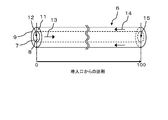
- FIG. 8 is a diagram illustrating the configuration of the double pipe 6 provided in the double pipe heat exchanger.
- a low-temperature flow path 8 is defined inside the inner pipe 7, and a high-temperature flow path 11 is defined between the outer pipe 9 and the inner pipe 7.
- a slurry body 13 is circulated through the low temperature flow path 8.
- a high-temperature fluid 14 that exchanges heat with the slurry body 13 flows through the high-temperature channel 11 in the opposite direction to the slurry body 13. Then, the slurry body 13 introduced from the inlet 12 of the low-temperature channel 8 is heated while exchanging heat with the high-temperature fluid 14 and discharged from the outlet 15.
- FIG. 9 is a diagram illustrating an example of a change in the temperature of the slurry body 13 and a change in the temperature of the high-temperature fluid 14 in the heat exchanger 3 including the double pipe 6.
- the vertical axis indicates the temperature of the fluid
- the horizontal axis indicates the distance of the double pipe 6.
- the distance of the double pipe 6 is from the inlet 12 when the position of the inlet 12 in the inner pipe 7 is 0 and the position of the outlet 15 is 100. Is the distance.
- the temperature of the slurry 13 introduced into the inlet 12 at room temperature is raised, but the intermediate portion 16 of the heat exchanger 3 (the temperature of the slurry 13 is about 380 ° C. It can be seen that the temperature increase rate of the slurry 13 is extremely slow at a distance of about 30 to about 70). Similarly, in the high temperature fluid 14, almost no temperature change is observed in the intermediate portion 16, and the temperature is about 380 ° C., which is substantially the same as that of the slurry body 13.
- the reason why the temperature change of the slurry body 13 and the high-temperature fluid 14 in the intermediate portion 16 is smaller than that of the other portions is that the constant pressure specific heat of the slurry body 13 and the high-temperature fluid 14 in the intermediate portion 16 is high. It is thought that it is because.
- the internal pressure of the heat exchanger 3 is a high pressure (for example, 25 MPa), but under such a high pressure, the constant pressure specific heat of the slurry body 13 and the high temperature fluid 14 is a specifically high peak near the critical temperature (about 380 ° C.). It is known to take a value.
- the constant pressure specific heat of the high temperature fluid 14 peaks at a temperature slightly lower than the constant pressure specific heat of the slurry body 13 due to pressure loss in the double pipe 6. For this reason, the temperature difference between the slurry body 13 and the high temperature fluid 14 is minimized in the intermediate portion 16, and the heat exchange amount per unit heat transfer area is a portion other than the intermediate portion, and the low temperature portion 17 and the high temperature of the heat exchanger 3. Smaller than the portion 18. As a result, the slurry body 13 is not easily heated.
- tar derived from biomass components is easily generated in the intermediate portion 16.
- the generated tar adheres to the inner wall of the inner pipe 7 to reduce the heat passage rate, and closes the pipe, thereby obstructing the flow of the slurry body 13 and further reducing the exchange heat per unit heat transfer area. It has become.
- the present invention has been made in view of such a current situation, and an object thereof is to provide a gasification system for efficiently gasifying biomass.
- the present invention provides a gasification system for generating a fuel gas by decomposing a slurry body produced by preparing biomass in a supercritical state, wherein a high-temperature fluid in a supercritical state is used.
- a heat exchanger that heats the slurry body by exchanging heat between the high-temperature fluid and the slurry body, and heats the slurry body that is sent from the heat exchanger, and the supercritical high-temperature fluid.
- the heat exchanger is configured by a high-temperature channel and a low-temperature channel, and the high-temperature fluid generated in the gasification reactor is circulated through the high-temperature channel.
- the low-temperature flow path is divided into a first block for circulating the slurry body and a second block for circulating a fluid having a pressure lower than that of the high-temperature fluid, which is used in a separate heat engine.
- Block Specific heat is provided such that said high-temperature fluid and the slurry body in a temperature range equal to or less than the predetermined value is the heat exchanger, the second block is provided in a portion other than the first block.
- the low-temperature flow path is divided into a first block that circulates the slurry body and a second block that circulates a fluid having a pressure lower than that of the high-temperature fluid used in a separate heat engine.
- the first block is provided so that heat can be exchanged between the slurry body and the high-temperature fluid in a temperature range in which the constant pressure specific heat becomes a predetermined value or less. For this reason, the temperature of the slurry body can be efficiently increased by the heat transferred from the high-temperature fluid to the slurry body. That is, it is possible to utilize a portion where the temperature exchange performance between the high-temperature fluid and the slurry body in the heat exchanger is high. As a result, biomass gasification can be performed efficiently. Furthermore, since the second block is arranged in a portion other than the first block, the thermal energy of the high-temperature fluid can be used as a heat source for another heat engine without waste.
- the fluid used in the separate heat engine is steam, and the separate heat engine uses steam generated by flowing through the second block as power. It preferably includes a turbine. In this configuration, the thermal energy supplied from the high-temperature fluid can be effectively used as power for the steam turbine.
- the exhaust gas discharged from the gasification reactor is circulated, and provided with an exhaust duct for exchanging heat between the exhaust gas and water obtained by agglomeration of water vapor that has finished work in the steam turbine. It is preferable. In this configuration, the thermal energy of the exhaust gas discharged from the gasification reactor can be effectively used as power for the steam turbine.
- the gasification system of the present invention can efficiently perform biomass gasification.
- FIG. 1 is a diagram illustrating a configuration of a gasification system 10 according to the first embodiment.
- a slurry body is prepared from biomass such as shochu residue, egg-collecting chicken manure, and sludge as raw materials, and combustion gas is generated by heating and pressurizing the prepared slurry body.
- the gasification system 10 includes a raw material preparation unit 20, a heat treatment unit 30, and a gas processing unit 40.
- the raw material preparation unit 20 is a part that prepares a slurry body from biomass.
- the raw material preparation unit includes a preparation tank 21, a pulverizer 22, a supply pump 23, and a heat exchanger introduction pump 24.
- Preparation tank 21 is a container for mixing biomass, water, and activated carbon (a kind of non-metallic catalyst).
- a mixture in which biomass, water, and activated carbon are mixed is prepared.
- porous particles having an average particle diameter of 200 ⁇ m or less are used as the activated carbon.
- the mixing ratio of biomass, water, and activated carbon is appropriately adjusted according to the type, amount, moisture content, and the like of biomass.
- the pulverizer 22 is an apparatus for crushing the solid content of the mixture prepared in the preparation tank 21 to obtain a uniform size (preferably an average particle size of 500 ⁇ m or less, more preferably an average particle size of 300 ⁇ m or less). is there. By being processed by the pulverizer 22, the mixture becomes a slurry-like slurry body.
- the supply pump 23 supplies the slurry discharged from the pulverizer 22 to the heat exchanger introduction pump 24.
- the heat exchanger introduction pump 24 pressurizes the slurry body sent from the supply pump 23 and supplies it to the heat treatment unit 30.
- the slurry body is pressurized to about 0.1 to 4 MPa by the heat exchanger introduction pump 24.
- the heat treatment part 30 is a part that heats and gasifies the slurry body prepared by the raw material preparation part 20.
- the heat treatment unit 30 includes a heat exchanger 31, a heater 32, a gasification reactor 33, and a power generation unit 34.
- the heat exchanger 31 is an apparatus for heating the slurry body sent from the raw material preparation unit 20.
- the heat exchanger 31 is a double tube heat exchanger including a double tube, and includes a low temperature channel 36 and a high temperature channel 37.
- the low-temperature flow path 36 is divided into a first block 36 a through which the slurry body sent from the raw material preparation unit 20 circulates and a second block 36 b through which steam for power of about a dozen MPa serving as power for the power generation unit 34 circulates. It is divided.
- a supercritical high-temperature fluid hereinafter also referred to as a processed fluid, which will be described later
- a processed fluid which will be described later
- the heater 32 is a device for heating the slurry body sent from the heat exchanger 31.
- the heater 32 includes a combustion device 32a.
- the combustion device 32a introduces the combustion gas sent from the gas processing unit 40 into liquefied petroleum gas such as propane gas or air and burns it, thereby heating the slurry body. To do. Thereby, the temperature of the slurry introduced into the heater 32 is raised to, for example, about 600 ° C.
- the heated slurry body is sent to the gasification reactor 33.
- the gasification reactor 33 keeps the slurry sent from the heater 32 constant at the gasification reaction temperature (temperature at which the slurry is gasified (gasification is possible)), and is contained in the slurry.
- the gasification reactor 33 includes a combustion device 33a.
- the combustion device 33a introduces combustion gas sent from the gas processing unit 40 into liquefied petroleum gas or air and burns it, and hydrothermally heats the slurry body.
- the slurry body is hydrothermally treated for 1 to 2 minutes under conditions of, for example, 600 ° C. and 25 MPa.
- the hydrothermally treated slurry body undergoes a gasification reaction and then is sent to the high-temperature channel 37 of the heat exchanger 31 as a post-treatment fluid.
- the power generation unit 34 is a part that generates power using the steam for power generated by the heat exchanger 31, and corresponds to a heat engine of another system.
- the power generation unit 34 includes a steam turbine 51, a generator 52, a condenser 53, and a pump 54.
- the steam turbine 51 is a device that performs work (rotational motion) with the power steam generated by the heat exchanger 31.
- the generator 52 is a device that generates power by the rotation of the steam turbine 51.
- the condenser 53 is a device that condenses water vapor that has finished work in the steam turbine.
- the pump 54 is a device that sends out the water obtained by aggregation to the heat exchanger 31.
- the steam turbine 51 is caused to work by the power steam generated by the heat exchanger 31 (second block 36b), and electric power is obtained from the generator 52. And the water vapor
- the gas processing unit 40 is a part that extracts fuel gas from the processed fluid sent from the heat exchanger 31.
- the gas processing unit 40 includes a decompression mechanism 41, a cooling mechanism 42, a gas-liquid separator 43, and a gas tank 44.
- the decompression mechanism 41 is a device that decompresses the treated fluid sent from the heat exchanger 31.
- the cooling mechanism 42 is a device that cools the processed fluid sent from the decompression mechanism 41.
- the gas-liquid separator 43 is a device that separates the treated fluid cooled by the cooling mechanism 42 into a liquid (a liquid containing activated carbon or ash) and a gas (a gas such as hydrogen or methane). Among these, the liquid is treated as drainage, and the gas is sent to the gas tank 44.
- the gas tank 44 is a container for storing the gas (generated gas) separated by the gas-liquid separator 43. Part of the product gas stored in the gas tank 44 is supplied to the heater 32 and the gasification reactor 33 and consumed as fuel gas. In addition, this fuel gas can also be used as a power generation or a power source.
- the low temperature flow path 36 is divided into the first block 36a through which the slurry body flows and the second block 36b through which power steam flows.
- the second block 36b is arranged on the upstream side (high temperature side) of the high temperature flow path 37
- the first block 36a is arranged on the downstream side (low temperature side) of the high temperature flow path 37.
- water sent from the pump 54 of the power generation unit 34 is evaporated by heat from the processed fluid, and power steam is generated.
- the generated power steam is heated by heat from the treated fluid, and the temperature and pressure are increased.
- the pressure of the power vapor is sufficiently lower than the pressure of the treated fluid, for example, about a dozen MPa. For this reason, the water and power steam sent from the pump 54 absorb the heat from the treated fluid and are quickly heated.
- the ratio of the length of the first block 36a and the second block 36b in the low-temperature channel 36 is determined based on the final heating temperature T1 of the slurry body.
- FIG. 3 is a graph showing the relationship between temperature, pressure, and constant pressure specific heat in water. From this graph, it can be seen that, under ultra-high pressure, the constant pressure specific heat in a specific temperature range (a range of about 370 ° C. to about 400 ° C.) called a pseudocritical point rapidly increases. And the slurry body which contains water as a main component also has the same characteristic.
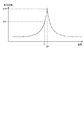
- FIG. 4 is a graph conceptually showing the relationship between the constant-pressure specific heat and temperature in the slurry body under 25 MPa.
- the constant pressure specific heat at the temperature TP shows the peak value SHP. If the specific heat at a constant pressure becomes too high, it becomes difficult for temperature changes to occur even if heat is absorbed or released. Therefore, in the present embodiment, the first block 36a is placed in the high-temperature channel 37 so that heat exchange is performed between the slurry body and the processed fluid in a temperature range where the constant pressure specific heat is equal to or less than the predetermined value SH1 (range of temperature T1 or less). It is arranged on the downstream side.
- SH1 range of temperature T1 or less
- the slurry body is heated by the heat transferred from the treated fluid to the slurry body, and the temperature rises.
- the heat exchange is performed in the range up to the temperature T1 at which the constant pressure specific heat is equal to or less than the predetermined value SHP, the slurry body can be efficiently heated to the temperature T1.
- the second block 36b is arranged on the upstream side of the high-temperature flow path 37, a portion of the thermal energy of the processed fluid that is not used for heating the slurry body is used in the power generation unit 34. It is possible to generate power steam of about several tens of MPa.
- an exhaust gas duct 55 is provided in the middle of a pipe connecting the condenser 53 and the pump 54, and the exhaust gas from the gasification reactor 33 is exhausted. It is characterized in that it is introduced into the duct 55. Since other configurations are the same as those in the first embodiment, description thereof is omitted.
- the exhaust gas from the gasification reactor 33 and the water from the condenser 53 are heat-exchanged by the exhaust gas duct 55, and the water from the condenser 53 is heated.
- the heated water is sent to the heat exchanger 31 by the pump 54, and power steam is generated.
- the thermal energy of the exhaust gas discharged from the gasification reactor 33 can be effectively used as power for the steam turbine.
- the raw material of the biomass may be other than the shochu residue, and may be, for example, egg-collecting chicken manure, sewage sludge or other water-containing biomass.
- water and a catalyst are mixed when generating a slurry body. However, these may not be mixed.
- the second block 36 b is disposed in the middle portion of the low temperature channel 36, which is a temperature region in which the constant pressure specific heat of the slurry body reaches a peak, and the low temperature of the low temperature channel 36. You may arrange
- the second block 36 b is arranged from the middle part of the low temperature channel 36 where the constant pressure specific heat of the slurry body reaches a peak to the low temperature side part, and the low temperature channel 36. You may arrange
- the first block 36a through which the slurry body circulates exchanges heat between the slurry body and the treated fluid in a temperature range where the constant pressure specific heat of the slurry body is a predetermined value or less.
- the second block 36b through which the low-pressure fluid used in the heat engine of another system flows may be provided in a portion other than the first block 36a in the low-temperature channel 36.
- the heat exchanger may be divided into a first heat exchanger and a second heat exchanger.
- first heat exchanger heat is exchanged between the processed fluid and the first block 36a
- second heat exchanger heat is exchanged between the processed fluid and the second block 36b. Good.
- the power generation unit 34 has been exemplified in the above-described embodiment.
- heating equipment, chemical reaction equipment, and other It may be a type of heat engine.
- the fluid used in another heat engine is not limited to water vapor. Any fluid having a lower pressure than the treated fluid may be used.
- Combustion device 33 ... Gasification reaction 33a ... combustion device 34 ... power generation unit 35 ... boiler 36 ... low temperature channel 36a ... first block of low temperature channel 36b ... second block of low temperature channel 37 ... high temperature channel 40 ... Gas processing unit 41 ... Depressurization mechanism 42 ... Cooling mechanism 43 ... Gas-liquid separator 44 ... Gas Tank, 51 ... steam turbines, 52 ... generator, 53 ... condenser 54 ... pumps, 55 ... exhaust gas duct
Landscapes
- Chemical & Material Sciences (AREA)
- Engineering & Computer Science (AREA)
- Combustion & Propulsion (AREA)
- Oil, Petroleum & Natural Gas (AREA)
- Organic Chemistry (AREA)
- Treatment Of Sludge (AREA)
- Processing Of Solid Wastes (AREA)
Abstract
本発明は、バイオマスを調製して生成されたスラリー体を、超臨界状態で分解処理して燃料ガスを生成するガス化システムに関し、バイオマスのガス化を効率よく行うことを目的とする。 本発明のガス化システム10では、超臨界状態の高温流体とスラリー体とを熱交換することでスラリー体を加熱する熱交換器31と、熱交換器31からのスラリー体を加熱し、前記超臨界状態の高温流体を生成するガス化反応器33とを備え、熱交換器31の高温流路37には、ガス化反応器33で生成された高温流体を流通させ、低温流路36は、スラリー体を流通させる第1ブロック36aと、別系統の熱機関で利用される、高温流体よりも低圧の流体を流通させる第2ブロック36bとに分割され、第1ブロック36aでは、定圧比熱が所定値以下となる温度域でスラリー体と高温流体とが熱交換される。第2ブロックは第1ブロック以外の部分に設けられる。
Description
本発明は、バイオマスを調製して生成されたスラリー体を、超臨界状態で分解処理して燃料ガスを生成するガス化システムに関する。
超臨界状態でバイオマスを分解処理して燃料ガスを得るガス化装置が知られている。例えば、特許文献1には、非金属系触媒を含んだバイオマスのスラリー体を温度374℃以上、圧力22.1MPa以上の条件下で水熱処理し、生成された燃料ガスを利用して発電装置で発電し、発電装置からの排熱を利用してスラリー体を加熱するバイオマスガス化発電システムが記載されている。
図7は、一般的なバイオマスガス化発電システムを説明する図である。同図に示すように、このガス化システム2は、熱交換器3、加熱器4、及びガス化反応器5を含んで構成される。これら各部の中で、熱交換器3は、スラリー状の原料(スラリー体)を加熱する装置である。このスラリー体は、例えば、焼酎残渣、採卵鶏糞、汚泥等のバイオマスに、水及び活性炭(触媒)を加えて混合することで調製される。加熱器4は、熱交換器3で加熱されたスラリー体をガス化反応温度(スラリー体がガス化する(ガス化が可能となる)温度)まで昇温する装置である。ガス化反応器5は、このスラリー体をガス化反応温度で一定に保持する装置である。ガス化反応が完了した流体は、その後気液分離され、気体分が燃料ガスとして利用される。
ここで、熱交換器3としては、例えば二重管式熱交換器が用いられる。図8は、この二重管式熱交換器が備える二重管6の構成を説明する図である。同図に示すように、二重管6では、内側の配管7の内側に低温流路8が区画され、外側の配管9と内側の配管7の間に高温流路11が区画されている。低温流路8には、スラリー体13が流通される。一方、高温流路11には、スラリー体13と熱交換される高温流体14が、スラリー体13とは反対方向に流通される。そして、低温流路8の導入口12から導入されたスラリー体13は、高温流体14と熱交換しながら加熱され、排出口15から排出される。
図9は、この二重管6を備えた熱交換器3における、スラリー体13の温度の変化、及び高温流体14の温度の変化の一例を示した図である。この図において、縦軸は流体の温度を示し、横軸は二重管6の距離を示している。二重管6の距離について補足すると、この二重管6の距離は、内側の配管7における導入口12の位置を0とし、排出口15の位置を100として表した場合の、導入口12からの距離である。
図9に示すように、常温で導入口12に導入されたスラリー体13は昇温されるが、熱交換器3の中間部分16(スラリー体13の温度が約380℃となり、導入口12からの距離が約30~約70までの部分)においては、スラリー体13の昇温速度が極めて遅いことが分かる。同様に、高温流体14についても中間部分16においては温度変化が殆ど見られず、その温度はスラリー体13とほぼ同じである約380℃でとなっている。
このように、中間部分16におけるスラリー体13と高温流体14の温度変化が、他の部分に比べて小さくなっている理由は、中間部分16におけるスラリー体13及び高温流体14の定圧比熱が高くなっているためと考えられる。
すなわち、熱交換器3の内部圧力は高圧(例えば25MPa)であるが、このような高圧下ではスラリー体13や高温流体14の定圧比熱は臨界温度付近(約380℃)において特異的に高いピーク値をとることが知られている。なお、実際には高温流体14の定圧比熱は二重管6における圧力損失のためスラリー体13の定圧比熱よりも少し低い温度でピークとなる。このため、中間部分16ではスラリー体13と高温流体14との間の温度差が極小化し、単位伝熱面積当たりの交換熱量が中間部分以外の部分である熱交換器3の低温部分17および高温部分18に比べて小さくなる。その結果、スラリー体13が昇温されにくい状態となっている。
また、この中間部分16ではバイオマスの成分に由来するタールが生成され易いことが知られている。生成されたタールは、内側の配管7の内壁に付着して熱通過率を低下させ、当該配管を閉塞させるのでスラリー体13の流通を妨げ、さらに単位伝熱面積当たりの交換熱量を減少させる原因となっている。
本発明はこのような現状に鑑みてなされたものであり、その目的は、バイオマスのガス化を効率よく行うためのガス化システムを提供することにある。
前記目的を達成するため、本発明は、バイオマスを調製して生成されたスラリー体を、超臨界状態で分解処理して燃料ガスを生成するガス化システムであって、超臨界状態の高温流体が導入され、前記高温流体と前記スラリー体とを熱交換することで前記スラリー体を加熱する熱交換器と、前記熱交換器から送出された前記スラリー体を加熱し、前記超臨界状態の高温流体を生成するガス化反応器とを備え、前記熱交換器は、高温流路及び低温流路によって構成され、前記高温流路には、前記ガス化反応器で生成された前記高温流体を流通させ、前記低温流路は、前記スラリー体を流通させる第1ブロックと、別系統の熱機関で利用される、前記高温流体よりも低圧の流体を流通させる第2ブロックとに分割され、前記第1ブロックは、定圧比熱が所定値以下となる温度域で前記スラリー体と前記高温流体とが熱交換されるように設けられ、前記第2ブロックは、前記第1ブロック以外の部分に設けられる。
本発明のガス化システムでは、低温流路が、スラリー体を流通させる第1ブロックと、別系統の熱機関で利用される、高温流体よりも低圧の流体を流通させる第2ブロックとに分割されている。さらにこのシステムでは、定圧比熱が所定値以下となる温度域でスラリー体と高温流体とが熱交換可能なように、第1ブロックが設けられている。このため、高温流体からスラリー体へ移動した熱によって、スラリー体の温度を効率よく上昇させることができる。すなわち、熱交換器における高温流体とスラリー体との間の温度交換性能が高い部分を活用することができる。その結果、バイオマスのガス化を効率よく行うことができる。さらに、第1ブロック以外の部分には第2ブロックが配置されているので、高温流体が有する熱エネルギーを、別の熱機関の熱源として無駄なく利用できる。
前述のガス化システムにおいて、前記別系統の熱機関で利用される前記流体は水蒸気であり、前記別系統の熱機関は、前記第2ブロックを流通することで生成された水蒸気を動力とする蒸気タービンを含むことが好ましい。この構成では、高温流体から供給される熱エネルギーを蒸気タービンの動力として有効利用できる。
前述のガス化システムにおいて、前記ガス化反応器から排出される排ガスが流通され、前記蒸気タービンでの仕事を終えた水蒸気の凝集で得られた水と前記排ガスとを熱交換させる排気ダクトを備えることが好ましい。この構成では、ガス化反応器から排出される排ガスの熱エネルギーを蒸気タービンの動力として有効利用できる。
本発明のガス化システムによれば、バイオマスのガス化を効率よく行える。
以下、本発明の実施の形態について説明する。まず、第1実施形態について説明する。図1は、第1実施形態に係るガス化システム10の構成を説明する図である。このガス化システム10では、原料である焼酎残渣、採卵鶏糞、汚泥等のバイオマスからスラリー体を調製し、調製したスラリー体を加熱加圧することにより燃焼ガスを生成する。同図に示すように、ガス化システム10は、原料調製部20、熱処理部30、及びガス処理部40を有する。
原料調製部20は、バイオマスからスラリー体を調製する部分である。原料調製部は、調製タンク21、粉砕機22、供給ポンプ23、及び熱交換器導入ポンプ24を備える。
調製タンク21は、バイオマスと、水と、活性炭(非金属系触媒の一種)を混合するための容器である。この調製タンク21では、バイオマス、水、及び、活性炭が混合された混合物が調製される。活性炭は、例えば平均粒径200μm以下の多孔質の粒子を用いる。なお、バイオマスと、水と、活性炭の混合割合は、バイオマスの種類、量、含水率などに応じて適宜調節される。
粉砕機22は、調製タンク21で調整された混合物の固形分を破砕し、均一な大きさ(好ましくは平均粒径が500μm以下、より好ましくは平均粒径が300μm以下)にするための装置である。この粉砕機22で処理されることにより、混合物はスラリー状のスラリー体となる。
供給ポンプ23は、粉砕機22から排出されたスラリー体を熱交換器導入ポンプ24に供給する。熱交換器導入ポンプ24は、供給ポンプ23から送られてきたスラリー体を加圧して熱処理部30に供給する。この熱交換器導入ポンプ24により、スラリー体は0.1~4MPa程度まで加圧される。
熱処理部30は、原料調製部20で調製されたスラリー体を加熱し、ガス化する部分である。この熱処理部30は、熱交換器31、加熱器32、ガス化反応器33、発電部34を備える。
熱交換器31は、原料調製部20から送られてきたスラリー体を加熱する装置である。熱交換器31は、二重管を備える二重管式熱交換器であり、低温流路36と高温流路37を備える。低温流路36は、原料調製部20から送られてきたスラリー体が流通する第1ブロック36aと、発電部34の動力となる十数MPa程度の動力用蒸気が流通する第2ブロック36bとに分割されている。一方、高温流路37には、ガス化反応器33で生成された超臨界状態の高温流体(以下、処理後流体ともいう。後述)が導入され、この処理後流体が流通する。そして、高温流路37を流れる処理後流体と、第1ブロック36aを流れるスラリー体や第2ブロック36bを流れる動力用蒸気とが熱交換される。なお、熱交換器31については、後で説明する。
加熱器32は、熱交換器31から送られてくるスラリー体を加熱する装置である。加熱器32は燃焼装置32aを備え、燃焼装置32aは、プロパンガス等の液化石油ガスや空気に、ガス処理部40から送られてくる燃焼ガスを導入して燃焼させ、これによりスラリー体を加熱する。これにより、加熱器32に導入されたスラリー体は、例えば約600℃程度までに昇温される。昇温されたスラリー体は、ガス化反応器33に送出される。
ガス化反応器33は、加熱器32から送られてきたスラリー体をガス化反応温度(スラリー体がガス化する(ガス化が可能となる)温度)で一定に保持し、スラリー体に含まれる有機物を水熱処理する装置である。ガス化反応器33は燃焼装置33aを備え、燃焼装置33aは、液化石油ガスや空気に、ガス処理部40から送られてくる燃焼ガスを導入して燃焼させ、スラリー体を水熱処理する。この水熱処理においてスラリー体は、例えば600℃、25MPaの条件下で、1~2分間にわたって水熱処理される。水熱処理されたスラリー体はガス化反応が進行したのち、処理後流体として、熱交換器31の高温流路37へ送出される。
発電部34は、熱交換器31で生成された動力用蒸気を用いて発電を行う部分であり、別系統の熱機関に相当する。この発電部34は、蒸気タービン51、発電機52、復水器53、及びポンプ54を備える。蒸気タービン51は、熱交換器31で生成された動力用蒸気で仕事(回転運動)をする装置である。発電機52は、蒸気タービン51の回転によって発電をする装置である。復水器53は、蒸気タービンでの仕事を終えた水蒸気を凝縮させる装置である。ポンプ54は、凝集で得られた水を熱交換器31へ送出する装置である。
この発電部34では、熱交換器31(第2ブロック36b)で生成された動力用蒸気によって蒸気タービン51に仕事をさせ、発電機52から電力を得ている。そして、仕事を終えた水蒸気を復水器53で凝縮させ、得られた水を熱交換器31へ送出することで、動力用蒸気を生成させている。
ガス処理部40は、熱交換器31から送出された処理後流体から燃料ガスを取り出す部分である。このガス処理部40は、減圧機構41、冷却機構42、気液分離器43、及びガスタンク44を備える。
減圧機構41は、熱交換器31から送出された処理後流体を減圧する装置である。冷却機構42は、減圧機構41から送られてきた処理後流体を冷却する装置である。気液分離器43は、冷却機構42で冷却された処理後流体を、液体(活性炭や灰分を含む液体)と、気体(水素やメタン等のガス)とに分離する装置である。このうち液体は排液として処理され、気体はガスタンク44に送られる。
ガスタンク44は、気液分離器43で分離した気体(生成ガス)を貯留する容器である。ガスタンク44に貯留された生成ガスの一部は、加熱器32、及びガス化反応器33に供給され、燃料ガスとして消費される。なお、この燃料ガスは、発電や動力源として用いることもできる。
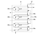
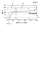
次に、熱交換器31について説明する。前述したように、本実施形態の熱交換器31では、低温流路36を、スラリー体が流通する第1ブロック36aと動力用蒸気が流通する第2ブロック36bに分割している。そして、第2ブロック36bを高温流路37の上流側(高温側)に配置し、第1ブロック36aを高温流路37の下流側(低温側)に配置している。
これにより、図2に示すように、熱交換器31におけるスラリー体の導入口(距離0)から距離L1までの区間では、高温流体(すなわち処理後流体)とスラリー体との間で熱交換が行われ、処理後流体から移動した熱によってスラリー体が加熱される。同様に、距離L1よりも後の距離L2から処理後流体の導入口(距離100)までの区間では、発電部34で用いられる流体との間で熱交換が行われる。
この区間では、発電部34のポンプ54から送出された水が処理後流体からの熱によって蒸発し、動力用蒸気が生成される。生成された動力用蒸気は、処理後流体からの熱によって加熱され、温度と圧力が高められる。ここで、動力用蒸気の圧力は、処理後流体の圧力よりも十分に低く、例えば十数MPa程度である。このため、ポンプ54から送出された水や動力用蒸気は、処理後流体からの熱を吸収して速やかに昇温される。
そして、低温流路36における第1ブロック36aと第2ブロック36bの長さの比率は、スラリー体の最終加熱温度T1に基づいて定められる。以下、この点について説明する。
図3は、水における温度、圧力、及び定圧比熱の関係を示すグラフである。このグラフより、超高圧の下で水は、擬臨界点と呼ばれる特定の温度範囲(約370℃から約400℃の範囲)の定圧比熱が急激に高くなることが判る。そして、水を主たる成分として含むスラリー体もまた、同様の特性を有している。
図4は、25MPaの下でのスラリー体における定圧比熱と温度の関係を概念的に示すグラフである。同図に示すように、このスラリー体では、温度TPにて定圧比熱がピーク値SHPを示している。そして、定圧比熱が高くなり過ぎると、熱の吸収や放出があっても温度の変化が生じ難くなる。そこで、本実施形態では、定圧比熱が所定値SH1以下となる温度域(温度T1以下の範囲)でスラリー体と処理後流体とが熱交換されるように、第1ブロック36aを高温流路37の下流側に配置している。
この構成では、処理後流体からスラリー体へ移動した熱によってスラリー体が加熱され、温度が上昇される。ここで、定圧比熱が所定値SHP以下となる温度T1までの範囲で熱交換を行わせているので、スラリー体を温度T1まで効率よく加熱することができる。言い換えれば、熱交換器における処理後流体とスラリー体との間の温度交換性能が高い部分を活用することができる。その結果、バイオマスのガス化を効率よく行うことができる。また、第2ブロック36bが高温流路37の上流側に配置されているので、処理後流体が有する熱エネルギーのうち、スラリー体の加熱に使われない部分を利用し、発電部34で使用される十数MPa程度の動力用蒸気を生成できる。
次に、図5を参照し、第2実施形態について説明する。同図に示すように、この第2実施形態では、発電部34に関し、復水器53とポンプ54とを接続する配管の途中に排ガスダクト55を設け、ガス化反応器33からの排ガスを排ガスダクト55に導入している点に特徴を有している。なお、他の構成については第1実施形態と同じであるので、その説明は省略する。
この第2実施形態では、ガス化反応器33からの排ガスと復水器53からの水とを排ガスダクト55で熱交換し、復水器53からの水を加熱している。加熱された水は、ポンプ54によって熱交換器31に送出され、動力用蒸気が生成される。この構成では、ガス化反応器33から排出される排ガスの熱エネルギーを蒸気タービンの動力として有効利用できる。
以上の実施形態の説明は、本発明の理解を容易にするためのものであり、本発明を限定するものではない。本発明はその趣旨を逸脱することなく、変更、改良され得ると共に本発明にはその等価物が含まれる。例えば、次のように構成してもよい。
例えば、バイオマスの原料は、焼酎残渣以外であってもよく、例えば、採卵鶏糞、下水汚泥他の含水性バイオマスでもよい。
また、上記の各実施形態では、スラリー体を生成する際に水や触媒を混合することとしたが、これらは混合しなくてもよい。
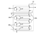
また、図6Aに示すように、熱交換器31に関し、スラリー体の定圧比熱がピークとなる温度域である低温流路36の中間部分に第2ブロック36bを配置し、低温流路36の低温側部分と高温側部分のそれぞれに第1ブロック36aを配置してもよい。
また、図6Bに示すように、熱交換器31に関し、スラリー体の定圧比熱がピークとなる低温流路36の中間部分から低温側部分に亘って第2ブロック36bを配置し、低温流路36の高温側部分に第1ブロック36aを配置してもよい。
要するに、熱交換器31の低温流路36に関して、スラリー体が流通する第1ブロック36aは、スラリー体の定圧比熱が所定値以下となる温度域で、スラリー体と処理後流体とが熱交換されるように設けられていればよく、別系統の熱機関で使用する低圧の流体が流通する第2ブロック36bは、低温流路36における第1ブロック36a以外の部分に設けられていればよい。
加えて、熱交換器を、第1熱交換器と第2熱交換器とに分けて構成してもよい。この場合、第1熱交換器では、処理後流体と第1ブロック36aの間で熱交換をさせ、第2熱交換器では、処理後流体と第2ブロック36bの間で熱交換をさせればよい。
また、別系統の熱機関に関し、前述の実施形態では発電部34を例示したが、高温流路37を流れる処理後流体の熱を利用するものであれば、加熱設備や化学反応設備や他の種類の熱機関であってもよい。この場合、別系統の熱機関で使用される流体も水蒸気に限られない。処理後流体よりも低い圧力の流体であればよい。
2…ガス化システム、3…熱交換器、4…加熱器、5…ガス化反応器、6…二重管、7…内側の配管、8…低温流路、9…外側の配管、10…ガス化システム、11…高温流路、12…導入口、13…スラリー体、14…高温流体、15…排出口、16…中間部分、17…低温部分、18…高温部分、20…原料調製部、21…調製タンク、22…粉砕機、23…供給ポンプ、24…熱交換器導入ポンプ、30…熱処理部、31…熱交換器、32…加熱器、32a…燃焼装置、33…ガス化反応器、33a…燃焼装置、34…発電部、35…ボイラ、36…低温流路、36a…低温流路の第1ブロック、36b…低温流路の第2ブロック、37…高温流路、40…ガス処理部、41…減圧機構、42…冷却機構、43…気液分離器、44…ガスタンク、51…蒸気タービン、52…発電機、53…復水器、54…ポンプ、55…排ガスダクト
Claims (3)
- バイオマスを調製して生成されたスラリー体を、超臨界状態で分解処理して燃料ガスを生成するガス化システムであって、
超臨界状態の高温流体が導入され、前記高温流体と前記スラリー体とを熱交換することで前記スラリー体を加熱する熱交換器と、
前記熱交換器から送出された前記スラリー体を加熱し、前記超臨界状態の高温流体を生成するガス化反応器とを備え、
前記熱交換器は、高温流路及び低温流路によって構成され、
前記高温流路には、前記ガス化反応器で生成された前記高温流体を流通させ、
前記低温流路は、前記スラリー体を流通させる第1ブロックと、別系統の熱機関で利用される、前記高温流体よりも低圧の流体を流通させる第2ブロックとに分割され、
前記第1ブロックは、定圧比熱が所定値以下となる温度域で前記スラリー体と前記高温流体とが熱交換されるように設けられ、
前記第2ブロックは、前記第1ブロック以外の部分に設けられる、ガス化システム。 - 前記別系統の熱機関で利用される前記流体は水蒸気であり、
前記別系統の熱機関は、前記第2ブロックを流通することで生成された水蒸気を動力とする蒸気タービンを含む、請求項1に記載のガス化システム。 - 前記ガス化反応器から排出される排ガスが流通され、前記蒸気タービンでの仕事を終えた水蒸気の凝集で得られた水と前記排ガスとを熱交換させる排気ダクトを備える、請求項2に記載のガス化システム。
Priority Applications (2)
| Application Number | Priority Date | Filing Date | Title |
|---|---|---|---|
| JP2016543766A JP6127215B2 (ja) | 2015-03-02 | 2015-03-02 | ガス化システム |
| PCT/JP2015/056093 WO2016139723A1 (ja) | 2015-03-02 | 2015-03-02 | ガス化システム |
Applications Claiming Priority (1)
| Application Number | Priority Date | Filing Date | Title |
|---|---|---|---|
| PCT/JP2015/056093 WO2016139723A1 (ja) | 2015-03-02 | 2015-03-02 | ガス化システム |
Publications (1)
| Publication Number | Publication Date |
|---|---|
| WO2016139723A1 true WO2016139723A1 (ja) | 2016-09-09 |
Family
ID=56848816
Family Applications (1)
| Application Number | Title | Priority Date | Filing Date |
|---|---|---|---|
| PCT/JP2015/056093 Ceased WO2016139723A1 (ja) | 2015-03-02 | 2015-03-02 | ガス化システム |
Country Status (2)
| Country | Link |
|---|---|
| JP (1) | JP6127215B2 (ja) |
| WO (1) | WO2016139723A1 (ja) |
Cited By (2)
| Publication number | Priority date | Publication date | Assignee | Title |
|---|---|---|---|---|
| JP6671677B1 (ja) * | 2019-04-25 | 2020-03-25 | 中国電力株式会社 | 超臨界水ガス化システム |
| JP6704587B1 (ja) * | 2019-04-25 | 2020-06-03 | 中国電力株式会社 | 超臨界水ガス化システム |
Citations (2)
| Publication number | Priority date | Publication date | Assignee | Title |
|---|---|---|---|---|
| JP2008142599A (ja) * | 2006-12-07 | 2008-06-26 | Hiroshima Univ | 超臨界水ガス化システムに用いる供給管、超臨界水ガス化システム及び超臨界水ガス化システムの運用方法 |
| JP2009242697A (ja) * | 2008-03-31 | 2009-10-22 | Hiroshima Univ | バイオマス処理方法 |
-
2015
- 2015-03-02 JP JP2016543766A patent/JP6127215B2/ja active Active
- 2015-03-02 WO PCT/JP2015/056093 patent/WO2016139723A1/ja not_active Ceased
Patent Citations (2)
| Publication number | Priority date | Publication date | Assignee | Title |
|---|---|---|---|---|
| JP2008142599A (ja) * | 2006-12-07 | 2008-06-26 | Hiroshima Univ | 超臨界水ガス化システムに用いる供給管、超臨界水ガス化システム及び超臨界水ガス化システムの運用方法 |
| JP2009242697A (ja) * | 2008-03-31 | 2009-10-22 | Hiroshima Univ | バイオマス処理方法 |
Cited By (4)
| Publication number | Priority date | Publication date | Assignee | Title |
|---|---|---|---|---|
| JP6671677B1 (ja) * | 2019-04-25 | 2020-03-25 | 中国電力株式会社 | 超臨界水ガス化システム |
| JP6704587B1 (ja) * | 2019-04-25 | 2020-06-03 | 中国電力株式会社 | 超臨界水ガス化システム |
| WO2020217399A1 (ja) * | 2019-04-25 | 2020-10-29 | 中国電力株式会社 | 超臨界水ガス化システム |
| WO2020217398A1 (ja) * | 2019-04-25 | 2020-10-29 | 中国電力株式会社 | 超臨界水ガス化システム |
Also Published As
| Publication number | Publication date |
|---|---|
| JP6127215B2 (ja) | 2017-05-10 |
| JPWO2016139723A1 (ja) | 2017-04-27 |
Similar Documents
| Publication | Publication Date | Title |
|---|---|---|
| JP6573261B2 (ja) | 超臨界水ガス化システム | |
| US8888872B2 (en) | Gasifier cooling system | |
| JP6070906B1 (ja) | 超臨界水ガス化システムおよびガス化方法 | |
| JP6488364B2 (ja) | 超臨界水ガス化システム | |
| CN204939232U (zh) | 超临界反应器及超临界反应系统 | |
| KR101862869B1 (ko) | 대체 천연 가스 생산 시스템 및 방법 | |
| JP6057362B1 (ja) | 超臨界水ガス化システム | |
| JP6127215B2 (ja) | ガス化システム | |
| JP4971399B2 (ja) | 蒸気発生装置 | |
| JP6704587B1 (ja) | 超臨界水ガス化システム | |
| JP2016070127A (ja) | ガスタービン | |
| JP6338080B2 (ja) | 超臨界水によるバイオマスガス化システム | |
| RU2679330C1 (ru) | Энергетический комплекс на основе газификации отходов биомассы | |
| JP5865553B1 (ja) | 超臨界流体によるガス化装置 | |
| CN114502881A (zh) | 蒸汽发生装置 | |
| JP5865554B1 (ja) | 超臨界流体によるガス化装置 | |
| JP2021096062A (ja) | 放射合成ガス冷却器 | |
| JP6020951B1 (ja) | ガス化システム、及びガス化システムにおけるガス化方法 | |
| JP6671677B1 (ja) | 超臨界水ガス化システム | |
| CN220355385U (zh) | 一种零碳排放电站锅炉系统 | |
| CN101906321B (zh) | 煤气站酚水处理工艺 | |
| JP4759545B2 (ja) | 重質油焚きガスタービンの発電システム | |
| TWI884662B (zh) | 燃氣輪機汽電共生系統、燃氣輪機汽電共生系統的改造方法、及燃氣輪機汽電共生系統用增設單元 | |
| RU2663830C2 (ru) | Способ работы газотурбинной установки и устройство для его осуществления | |
| EP2792847A2 (en) | Heat and power plant with a waste gasification system |
Legal Events
| Date | Code | Title | Description |
|---|---|---|---|
| ENP | Entry into the national phase |
Ref document number: 2016543766 Country of ref document: JP Kind code of ref document: A |
|
| 121 | Ep: the epo has been informed by wipo that ep was designated in this application |
Ref document number: 15883893 Country of ref document: EP Kind code of ref document: A1 |
|
| NENP | Non-entry into the national phase |
Ref country code: DE |
|
| 122 | Ep: pct application non-entry in european phase |
Ref document number: 15883893 Country of ref document: EP Kind code of ref document: A1 |