WO2016136995A1 - Sliding bearing - Google Patents
Sliding bearing Download PDFInfo
- Publication number
- WO2016136995A1 WO2016136995A1 PCT/JP2016/055950 JP2016055950W WO2016136995A1 WO 2016136995 A1 WO2016136995 A1 WO 2016136995A1 JP 2016055950 W JP2016055950 W JP 2016055950W WO 2016136995 A1 WO2016136995 A1 WO 2016136995A1
- Authority
- WO
- WIPO (PCT)
- Prior art keywords
- inner peripheral
- coating layer
- narrow groove
- inclined portion
- half member
- Prior art date
Links
- 230000002093 peripheral effect Effects 0.000 claims abstract description 42
- 239000011247 coating layer Substances 0.000 claims abstract description 33
- 238000011144 upstream manufacturing Methods 0.000 claims description 14
- OKTJSMMVPCPJKN-UHFFFAOYSA-N Carbon Chemical compound [C] OKTJSMMVPCPJKN-UHFFFAOYSA-N 0.000 claims description 12
- 229910052582 BN Inorganic materials 0.000 claims description 6
- PZNSFCLAULLKQX-UHFFFAOYSA-N Boron nitride Chemical compound N#B PZNSFCLAULLKQX-UHFFFAOYSA-N 0.000 claims description 6
- YCKRFDGAMUMZLT-UHFFFAOYSA-N Fluorine atom Chemical compound [F] YCKRFDGAMUMZLT-UHFFFAOYSA-N 0.000 claims description 6
- 229910052799 carbon Inorganic materials 0.000 claims description 6
- 239000011737 fluorine Substances 0.000 claims description 6
- 229910052731 fluorine Inorganic materials 0.000 claims description 6
- 229910002804 graphite Inorganic materials 0.000 claims description 6
- 239000010439 graphite Substances 0.000 claims description 6
- CWQXQMHSOZUFJS-UHFFFAOYSA-N molybdenum disulfide Chemical compound S=[Mo]=S CWQXQMHSOZUFJS-UHFFFAOYSA-N 0.000 claims description 6
- 229910052982 molybdenum disulfide Inorganic materials 0.000 claims description 6
- -1 polytetrafluoroethylene Polymers 0.000 claims description 6
- 229920001343 polytetrafluoroethylene Polymers 0.000 claims description 6
- 239000004810 polytetrafluoroethylene Substances 0.000 claims description 6
- 239000011347 resin Substances 0.000 claims description 6
- 229920005989 resin Polymers 0.000 claims description 6
- ITRNXVSDJBHYNJ-UHFFFAOYSA-N tungsten disulfide Chemical compound S=[W]=S ITRNXVSDJBHYNJ-UHFFFAOYSA-N 0.000 claims description 6
- 230000001603 reducing effect Effects 0.000 abstract description 5
- 239000003921 oil Substances 0.000 description 13
- 230000013011 mating Effects 0.000 description 7
- 230000000694 effects Effects 0.000 description 6
- 239000000428 dust Substances 0.000 description 5
- 238000000034 method Methods 0.000 description 4
- 239000000126 substance Substances 0.000 description 3
- 239000010687 lubricating oil Substances 0.000 description 2
- 239000000463 material Substances 0.000 description 2
- 230000000116 mitigating effect Effects 0.000 description 2
- 230000007423 decrease Effects 0.000 description 1
Images

Classifications
-
- F—MECHANICAL ENGINEERING; LIGHTING; HEATING; WEAPONS; BLASTING
- F16—ENGINEERING ELEMENTS AND UNITS; GENERAL MEASURES FOR PRODUCING AND MAINTAINING EFFECTIVE FUNCTIONING OF MACHINES OR INSTALLATIONS; THERMAL INSULATION IN GENERAL
- F16C—SHAFTS; FLEXIBLE SHAFTS; ELEMENTS OR CRANKSHAFT MECHANISMS; ROTARY BODIES OTHER THAN GEARING ELEMENTS; BEARINGS
- F16C33/00—Parts of bearings; Special methods for making bearings or parts thereof
- F16C33/02—Parts of sliding-contact bearings
- F16C33/04—Brasses; Bushes; Linings
- F16C33/06—Sliding surface mainly made of metal
- F16C33/08—Attachment of brasses, bushes or linings to the bearing housing
-
- F—MECHANICAL ENGINEERING; LIGHTING; HEATING; WEAPONS; BLASTING
- F16—ENGINEERING ELEMENTS AND UNITS; GENERAL MEASURES FOR PRODUCING AND MAINTAINING EFFECTIVE FUNCTIONING OF MACHINES OR INSTALLATIONS; THERMAL INSULATION IN GENERAL
- F16C—SHAFTS; FLEXIBLE SHAFTS; ELEMENTS OR CRANKSHAFT MECHANISMS; ROTARY BODIES OTHER THAN GEARING ELEMENTS; BEARINGS
- F16C33/00—Parts of bearings; Special methods for making bearings or parts thereof
- F16C33/02—Parts of sliding-contact bearings
- F16C33/04—Brasses; Bushes; Linings
- F16C33/06—Sliding surface mainly made of metal
- F16C33/10—Construction relative to lubrication
- F16C33/1025—Construction relative to lubrication with liquid, e.g. oil, as lubricant
- F16C33/106—Details of distribution or circulation inside the bearings, e.g. details of the bearing surfaces to affect flow or pressure of the liquid
- F16C33/1065—Grooves on a bearing surface for distributing or collecting the liquid
-
- F—MECHANICAL ENGINEERING; LIGHTING; HEATING; WEAPONS; BLASTING
- F16—ENGINEERING ELEMENTS AND UNITS; GENERAL MEASURES FOR PRODUCING AND MAINTAINING EFFECTIVE FUNCTIONING OF MACHINES OR INSTALLATIONS; THERMAL INSULATION IN GENERAL
- F16C—SHAFTS; FLEXIBLE SHAFTS; ELEMENTS OR CRANKSHAFT MECHANISMS; ROTARY BODIES OTHER THAN GEARING ELEMENTS; BEARINGS
- F16C17/00—Sliding-contact bearings for exclusively rotary movement
- F16C17/02—Sliding-contact bearings for exclusively rotary movement for radial load only
- F16C17/022—Sliding-contact bearings for exclusively rotary movement for radial load only with a pair of essentially semicircular bearing sleeves
-
- F—MECHANICAL ENGINEERING; LIGHTING; HEATING; WEAPONS; BLASTING
- F16—ENGINEERING ELEMENTS AND UNITS; GENERAL MEASURES FOR PRODUCING AND MAINTAINING EFFECTIVE FUNCTIONING OF MACHINES OR INSTALLATIONS; THERMAL INSULATION IN GENERAL
- F16C—SHAFTS; FLEXIBLE SHAFTS; ELEMENTS OR CRANKSHAFT MECHANISMS; ROTARY BODIES OTHER THAN GEARING ELEMENTS; BEARINGS
- F16C33/00—Parts of bearings; Special methods for making bearings or parts thereof
- F16C33/02—Parts of sliding-contact bearings
- F16C33/04—Brasses; Bushes; Linings
- F16C33/046—Brasses; Bushes; Linings divided or split, e.g. half-bearings or rolled sleeves
-
- F—MECHANICAL ENGINEERING; LIGHTING; HEATING; WEAPONS; BLASTING
- F16—ENGINEERING ELEMENTS AND UNITS; GENERAL MEASURES FOR PRODUCING AND MAINTAINING EFFECTIVE FUNCTIONING OF MACHINES OR INSTALLATIONS; THERMAL INSULATION IN GENERAL
- F16C—SHAFTS; FLEXIBLE SHAFTS; ELEMENTS OR CRANKSHAFT MECHANISMS; ROTARY BODIES OTHER THAN GEARING ELEMENTS; BEARINGS
- F16C33/00—Parts of bearings; Special methods for making bearings or parts thereof
- F16C33/02—Parts of sliding-contact bearings
- F16C33/04—Brasses; Bushes; Linings
- F16C33/06—Sliding surface mainly made of metal
- F16C33/10—Construction relative to lubrication
-
- F—MECHANICAL ENGINEERING; LIGHTING; HEATING; WEAPONS; BLASTING
- F16—ENGINEERING ELEMENTS AND UNITS; GENERAL MEASURES FOR PRODUCING AND MAINTAINING EFFECTIVE FUNCTIONING OF MACHINES OR INSTALLATIONS; THERMAL INSULATION IN GENERAL
- F16C—SHAFTS; FLEXIBLE SHAFTS; ELEMENTS OR CRANKSHAFT MECHANISMS; ROTARY BODIES OTHER THAN GEARING ELEMENTS; BEARINGS
- F16C9/00—Bearings for crankshafts or connecting-rods; Attachment of connecting-rods
- F16C9/02—Crankshaft bearings
Definitions
- the present invention relates to a slide bearing technique, and more particularly to a slide bearing technique in which a half member in which a cylinder is divided into two in parallel to the axial direction is arranged vertically.
- the present invention provides a plain bearing capable of suppressing the total amount of oil spilled and obtaining a further friction reduction effect.
- the present invention is a plain bearing in which a half member divided into two in parallel with the axial direction of the cylinder is arranged vertically, and at the axial end of the lower half member, on the downstream side in the rotational direction.
- a narrow groove is provided in the circumferential direction
- An inclined portion that inclines toward the inner peripheral side toward the downstream side is provided at the downstream end portion in the rotation direction of the narrow groove, and a coating layer is provided on at least a part of the inner peripheral surface of the inclined portion.
- an inclined portion that is inclined toward the inner peripheral side toward the upstream side is provided at the upstream end portion in the rotation direction of the narrow groove, and a coating layer is provided on at least a part of the inner peripheral surface of the inclined portion. It is.
- the coating layer contains at least one of molybdenum disulfide, graphite, carbon, polytetrafluoroethylene, boron nitride, tungsten disulfide, or fluorine-based resin.
- A The top view which shows the half member which comprises the slide bearing which concerns on embodiment of this invention.
- B Sectional view taken along line II (B) -II (B).
- C Sectional view taken along line II (C) -II (C).
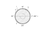
- FIG. 1 is a front view of the sliding bearing 1, where the top and bottom of the screen is the vertical direction, and the front and back directions of the screen are the axial directions (front and back directions).
- the slide bearing 1 is a cylindrical member and is applied to a slide bearing structure of an engine crankshaft 11 as shown in FIG.
- the plain bearing 1 is composed of two halved members 2 and 2.
- the two halved members 2 and 2 have a shape obtained by dividing a cylinder into two in parallel to the axial direction, and are formed so that the cross section is a semicircular shape.
- the half members 2 and 2 are arranged up and down, and mating surfaces are arranged on the left and right.
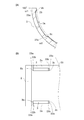
- FIG. 2 (A) the upper and lower half members 2 are shown.
- the rotation direction of the crankshaft 11 is the clockwise direction when viewed from the front as indicated by the arrow in FIG.
- the bearing angle ⁇ is 0 degree at the right end position in FIG. 2B, and the counterclockwise direction in FIG. 2B is positive. That is, in FIG. 2B, the bearing angle ⁇ at the left end position is defined as 180 degrees, and the bearing angle ⁇ at the lower end position is defined as 270 degrees.
- a groove is provided in the circumferential direction, and a circular hole is provided in the center.
- mating surfaces are arranged on the left and right of the upper half member 2.
- a narrow groove 3 is formed at the end in the axial direction.
- a coating layer 23 is provided on the inner peripheral surface of the lower half member 2 as shown in FIG.
- the coating layer 23 contains at least one of molybdenum disulfide, graphite, carbon, polytetrafluoroethylene, boron nitride, tungsten disulfide, or a fluorine-based resin.
- the peripheral edge 2a that forms the axially outer side surface of the narrow groove 3 has a height h from the outer peripheral surface of the half member 2 higher than the height D from the outer peripheral surface of the half member 2 to the contact surface. It is formed to be low. That is, the outer peripheral edge 2a in the axial direction is formed to be one step lower than the contact surface with the surrounding crankshaft 11.
- the narrow groove 3 will be described with reference to FIGS. 2 (B) and 2 (C).
- the narrow groove 3 is provided in the lower half member 2.
- two narrow grooves 3 are provided in parallel in the axial direction.
- the narrow groove 3 is formed in a direction in which the bearing angle ⁇ is positive (counterclockwise) from a position (the bearing angle ⁇ is ⁇ 1) that is separated from the mating surface on the downstream side in the rotation direction of the crankshaft 11 (the bearing angle ⁇ is 180 degrees).
- the bearing angle ⁇ is 180 degrees.
- the right mating surface in FIG. 2B is the upstream mating surface in the rotational direction
- the width of the narrow groove 3 is formed to be w as shown in FIG.
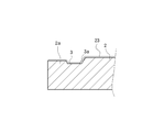
- the depth d of the narrow groove 3 is formed to be shorter than the height D from the outer peripheral surface of the half member 2 to the contact surface. Further, the depth d to the bottom surface 3a of the narrow groove 3 changes as it goes from one end to the other end in the longitudinal direction of the narrow groove 3, as shown in FIG.
- an inclined portion 3 b is provided at the downstream end of the narrow groove 3 in the rotation direction.
- the inclined portion 3b is a portion that is inclined toward the inner peripheral side toward the downstream side, and incline toward the downstream side in a sectional view parallel to the longitudinal direction (sectional view taken along line II (B) -II (B)). It is formed in a steep curve.
- an inclined portion 3 c is provided at the upstream end portion in the rotation direction of the narrow groove 3.
- the inclined portion 3c is a portion that is inclined toward the inner peripheral side toward the downstream side, and incline toward the upstream side in a cross-sectional view parallel to the longitudinal direction (II (B) -II (B) cross-sectional view). It is formed in a steep curve.
- coating layers 23a and 23a are provided on at least a part of the inner peripheral surfaces of the inclined portion 3b and the inclined portion 3c.
- the coating layer 23 contains molybdenum disulfide, graphite, carbon, polytetrafluoroethylene, boron nitride, tungsten disulfide, or a fluorine-based resin. By comprising in this way, the coating layer 23 has lipophilicity.
- peripheral edge portion 2a is formed so as to be one step lower than the contact surface with the surrounding crankshaft 11, the crankshaft 11 is inclined and is in contact with only one end portion in the axial direction. Since the chance of contact between the peripheral edge 2a and the crankshaft 11 can be reduced, damage to the peripheral edge 2a can be prevented.
- peripheral edge portion 2a is formed so as to be one step lower than the surrounding contact surface, the gap at the axial end portion of the slide bearing 1 is widened, and the amount of sucked-back oil is increased and the total amount of oil spilled Is reduced.
- coating layers 23b and 23b are provided on the inner peripheral surfaces of the upstream end and the downstream end of the peripheral edge 2a. Since the coating layers 23b and 23b provided on the inner peripheral surface of the peripheral edge 2a have low hardness, foreign matters such as dust can be buried in the coating layers 23b and 23b and collected. By comprising in this way, the damage of the surface of the crankshaft 11 and the internal peripheral surface of the slide bearing 1 by a foreign material can be prevented.
- the provision of the narrow groove 3 according to the present embodiment increases the FMEP mitigation amount.
- the FMEP reduction amount increases in a region where the engine speed is low.
- FMEP is a value for seeing the tendency of friction, and the friction decreases as the FMEP reduction amount increases. For example, when the engine is cold started, the FMEP mitigation amount increases and friction is reduced.
- the coating layer 23 is formed by being applied on the inner peripheral surface of the half member 2. At this time, as shown in FIG. 3A, the coating layer 23 is formed so as to cover the inner end portion in the axial direction, and more specifically, it is applied to the middle portion of the side surface on the inner side in the axial direction of the narrow groove 3. Has been. With this configuration, the inner end of the narrow groove 3 in the axial direction is covered with the coating layer 23, so that the crankshaft 11 is inclined and comes into contact with only one end in the axial direction (a state where it comes into contact with each other). The friction between the axially inner end of the narrow groove 3 and the crankshaft 11 can be reduced.
- the coating layer 23 can also be formed so as to cover the entire narrow groove 3.
- the slide bearing 1 is formed by vertically arranging the half members 2 and 2 which are divided into two parallel to the axial direction, and is disposed downstream of the axial direction end of the lower half member 2 in the rotational direction.
- the narrow groove 3 is provided in the circumferential direction on the side, and an inclined portion 3b that is inclined toward the inner peripheral side toward the downstream side is provided at the downstream end in the rotation direction of the fine groove 3, and at least one of the inner peripheral surfaces of the inclined portion 3b is provided.
- the coating layer 23a is provided on the part.
- the inclined portion 3b is provided at the downstream end of the narrow groove 3 in the rotation direction, and the coating layer 23a is provided on the inner peripheral surface of the inclined portion 3b.
- the coating layer 23a since it is collected in the coating layer 23a, damage to the surface of the crankshaft 11 and the inner peripheral surface of the slide bearing 1 due to foreign matter can be prevented.
- an inclined portion 3c that is inclined toward the inner peripheral side toward the upstream side is provided at the upstream end portion in the rotation direction of the narrow groove 3, and a coating layer 23a is provided on at least a part of the inner peripheral surface of the inclined portion 3c. is there.
- the coating layer 23 includes at least one of molybdenum disulfide, graphite, carbon, polytetrafluoroethylene, boron nitride, tungsten disulfide, and fluorine resin.
- the coating layer 23a provided on the inclined portion 3b at the downstream end and the inclined portion 3c at the upstream end of the narrow groove 3 is composed of molybdenum disulfide, graphite, carbon, polytetrafluoroethylene, boron nitride, tungsten disulfide.
- fluorine-based resins the hardness becomes low and foreign substances such as dust are easily collected.
- the present invention can be used for a slide bearing technique, and can be used for a slide bearing technique in which a half member in which a cylinder is divided into two in parallel with an axial direction is arranged vertically.
Landscapes
- Engineering & Computer Science (AREA)
- General Engineering & Computer Science (AREA)
- Mechanical Engineering (AREA)
- Chemical & Material Sciences (AREA)
- Oil, Petroleum & Natural Gas (AREA)
- Sliding-Contact Bearings (AREA)
- Shafts, Cranks, Connecting Bars, And Related Bearings (AREA)
Abstract
Description
前記細溝の回転方向下流側端部に下流側へ向かうにつれて内周側へ傾斜する傾斜部を設け、前記傾斜部の内周面の少なくとも一部にコーティング層を設けたものである。 That is, in the present invention, it is a plain bearing in which a half member divided into two in parallel with the axial direction of the cylinder is arranged vertically, and at the axial end of the lower half member, on the downstream side in the rotational direction. A narrow groove is provided in the circumferential direction,
An inclined portion that inclines toward the inner peripheral side toward the downstream side is provided at the downstream end portion in the rotation direction of the narrow groove, and a coating layer is provided on at least a part of the inner peripheral surface of the inclined portion.
すべり軸受1は円筒状の部材であり、図1に示すように、エンジンのクランクシャフト11のすべり軸受構造に適用される。すべり軸受1は、二つの半割部材2・2で構成されている。二つの半割部材2・2は、円筒を軸方向と平行に二分割した形状であり、断面が半円状となるように形成されている。本実施形態においては、半割部材2・2は上下に配置されており、左右に合わせ面が配置されている。クランクシャフト11をすべり軸受1で軸支する場合、所定の隙間が形成され、この隙間に対し図示せぬ油路から潤滑油が供給される。 First, the
The slide bearing 1 is a cylindrical member and is applied to a slide bearing structure of an
下側の半割部材2の内周において、その軸方向の端部に細溝3が形成されている。また、下側の半割部材2の内周面には、図2(C)に示すように、コーティング層23が設けられている。
コーティング層23は、二硫化モリブデン、グラファイト、カーボン、ポリテトラフルオロエチレン、窒化ホウ素、二硫化タングステン、または、フッ素系樹脂の少なくともいずれか一つを含むものである。 On the inner periphery of the
On the inner periphery of the
The
細溝3は下側の半割部材2に設けられる。本実施形態においては、細溝3は軸方向に並列して二本設けられている。詳細には、細溝3は、クランクシャフト11の回転方向下流側合わせ面(軸受角度ωが180度)と離間した位置(軸受角度ωがω1)から軸受角度ωが正となる方向(反時計回り方向)に向けて、軸受角度ω2まで円周方向に設けられる。下側の半割部材2においては、図2(B)の右側の合わせ面が回転方向上流側合わせ面、図2(B)の左側の合わせ面が回転方向下流側合わせ面となる。
細溝3の幅は、図2(C)に示すように、wとなるように形成されている。
また、細溝3の深さdは、半割部材2の外周面から当接面までの高さDよりも短くなるように形成されている。また、細溝3の底面3aまでの深さdは、図3(A)に示すように、細溝3の長手方向一端から他端に向かうにつれて変化する。 The
The
The width of the
Further, the depth d of the
また、細溝3の回転方向上流側端部には傾斜部3cが設けられている。傾斜部3cは、下流側へ向かうにつれて内周側へ傾斜する部分であり、長手方向と平行な断面視(II(B)-II(B)線断面視)において、上流側へ向かうにつれて傾きが急になる曲線状に形成されている。
図3(A)及び(B)に示すように、傾斜部3b及び傾斜部3cの内周面の少なくとも一部にはコーティング層23a・23aが設けられている。 As shown in FIGS. 2B and 3, an
Further, an
As shown in FIGS. 3A and 3B, coating layers 23a and 23a are provided on at least a part of the inner peripheral surfaces of the
周縁部2aの内周面に設けられたコーティング層23b・23bの硬度が低いため、塵埃などの異物をコーティング層23b・23bに埋収させて捕集することができる。このように構成することにより、異物によるクランクシャフト11の表面及びすべり軸受1の内周面の損傷を防止することができる。 Further, coating layers 23b and 23b are provided on the inner peripheral surfaces of the upstream end and the downstream end of the
Since the coating layers 23b and 23b provided on the inner peripheral surface of the
このように構成することにより、油膜圧力の発生を妨げない程度の細溝3を設けることで、摺動面積を減らしつつ、フリクション低減効果を得ることができ、かつ、総和の流出油量を抑えることができる。また、細溝3の回転方向下流側端部に傾斜部3bを設け、傾斜部3bの内周面にコーティング層23aを設けたことにより、細溝3の回転方向下流側端部に溜まった異物が、コーティング層23aにおいて捕集されるため、異物によるクランクシャフト11の表面及びすべり軸受1の内周面の損傷を防止することができる。 As described above, the
With this configuration, by providing the
このように構成することにより、細溝3の回転方向上流側端部に溜まった異物が、コーティング層23aにおいて捕集されるため、異物によるクランクシャフト11の表面及びすべり軸受1の内周面の損傷を防止することができる。 Further, an
By configuring in this way, foreign matter accumulated at the upstream end in the rotational direction of the
このように構成することにより、潤滑油とのなじみ性が向上し、漏れ油量を減少させることで、総和の流出油量を抑えることができる。また、細溝3の下流側端部の傾斜部3b及び上流側端部の傾斜部3cに設けられたコーティング層23aが二硫化モリブデン、グラファイト、カーボン、ポリテトラフルオロエチレン、窒化ホウ素、二硫化タングステン、または、フッ素系樹脂の少なくともいずれか一つを含むことにより、硬度が低くなり、塵埃等の異物を捕集しやすくなる。 The
By configuring in this way, the compatibility with the lubricating oil is improved, and the total amount of oil spilled can be suppressed by reducing the amount of oil leaked. The
2 半割部材
2a 周縁部
3 細溝
3a 底面
3b 傾斜部
3c 傾斜部
11 クランクシャフト
23・23a コーティング層 DESCRIPTION OF
Claims (3)
- 円筒を軸方向と平行に二分割した半割部材を上下に配置したすべり軸受であって、前記下側の半割部材の軸方向端部に、回転方向下流側において円周方向に細溝を設け、
前記細溝の回転方向下流側端部に下流側へ向かうにつれて内周側へ傾斜する傾斜部を設け、前記傾斜部の内周面の少なくとも一部にコーティング層を設けたことを特徴とするすべり軸受。 A slide bearing in which a half member divided into two in parallel to the axial direction is arranged vertically, and a narrow groove is formed in the circumferential direction on the downstream side in the rotational direction at the axial end of the lower half member. Provided,
A slip characterized in that an inclined portion that inclines toward the inner peripheral side toward the downstream side is provided at the downstream end portion in the rotation direction of the narrow groove, and a coating layer is provided on at least a part of the inner peripheral surface of the inclined portion. bearing. - 前記細溝の回転方向上流側端部に上流側へ向かうにつれて内周側へ傾斜する傾斜部を設け、前記傾斜部の内周面の少なくとも一部にコーティング層を設けたことを特徴とする請求項1に記載のすべり軸受。 An inclined portion that inclines toward the inner peripheral side toward the upstream side is provided at an upstream end portion in the rotation direction of the narrow groove, and a coating layer is provided on at least a part of the inner peripheral surface of the inclined portion. Item 6. The plain bearing according to item 1.
- 前記コーティング層は、二硫化モリブデン、グラファイト、カーボン、ポリテトラフルオロエチレン、窒化ホウ素、二硫化タングステン、または、フッ素系樹脂の少なくともいずれか一つを含むことを特徴とする請求項1または請求項2に記載のすべり軸受。 3. The coating layer according to claim 1, wherein the coating layer includes at least one of molybdenum disulfide, graphite, carbon, polytetrafluoroethylene, boron nitride, tungsten disulfide, or a fluorine-based resin. The plain bearing described in 1.
Priority Applications (5)
| Application Number | Priority Date | Filing Date | Title |
|---|---|---|---|
| EP16755739.6A EP3263929A4 (en) | 2015-02-27 | 2016-02-26 | Sliding bearing |
| CN201680012652.4A CN107407331A (en) | 2015-02-27 | 2016-02-26 | Sliding bearing |
| KR1020177027289A KR20170121259A (en) | 2015-02-27 | 2016-02-26 | Sliding bearing |
| PCT/JP2016/055950 WO2016136995A1 (en) | 2015-02-27 | 2016-02-26 | Sliding bearing |
| US15/553,814 US10054162B2 (en) | 2015-02-27 | 2016-02-26 | Sliding bearing |
Applications Claiming Priority (3)
| Application Number | Priority Date | Filing Date | Title |
|---|---|---|---|
| JP2015-039118 | 2015-02-27 | ||
| JP2015039118A JP6314103B2 (en) | 2015-02-27 | 2015-02-27 | Plain bearing |
| PCT/JP2016/055950 WO2016136995A1 (en) | 2015-02-27 | 2016-02-26 | Sliding bearing |
Publications (1)
| Publication Number | Publication Date |
|---|---|
| WO2016136995A1 true WO2016136995A1 (en) | 2016-09-01 |
Family
ID=56788568
Family Applications (1)
| Application Number | Title | Priority Date | Filing Date |
|---|---|---|---|
| PCT/JP2016/055950 WO2016136995A1 (en) | 2015-02-27 | 2016-02-26 | Sliding bearing |
Country Status (6)
| Country | Link |
|---|---|
| US (1) | US10054162B2 (en) |
| EP (1) | EP3263929A4 (en) |
| JP (1) | JP6314103B2 (en) |
| KR (1) | KR20170121259A (en) |
| CN (1) | CN107407331A (en) |
| WO (1) | WO2016136995A1 (en) |
Families Citing this family (2)
| Publication number | Priority date | Publication date | Assignee | Title |
|---|---|---|---|---|
| JP2019108923A (en) * | 2017-12-18 | 2019-07-04 | トヨタ自動車株式会社 | Thrust bearing and bearing device |
| JP2020045925A (en) * | 2018-09-14 | 2020-03-26 | 大豊工業株式会社 | Slide bearing |
Citations (4)
| Publication number | Priority date | Publication date | Assignee | Title |
|---|---|---|---|---|
| JP2009520926A (en) * | 2005-12-21 | 2009-05-28 | マーレ インターナショナル ゲゼルシャフト ミット ベシュレンクテル ハフツング | Connecting rod for internal combustion engine and method of manufacturing the same |
| JP2012047276A (en) * | 2010-08-27 | 2012-03-08 | Taiho Kogyo Co Ltd | Sliding bearing and method for manufacturing the same |
| JP2014508258A (en) * | 2011-03-11 | 2014-04-03 | フエデラル―モーグル・ウイースバーデン・ゲゼルシヤフト・ミト・ベシユレンクテル・ハフツング | Sliding bearing shell with collecting groove |
| JP2014126069A (en) * | 2012-12-25 | 2014-07-07 | Taiho Kogyo Co Ltd | Halved thrust bearing |
Family Cites Families (16)
| Publication number | Priority date | Publication date | Assignee | Title |
|---|---|---|---|---|
| US4597676A (en) * | 1984-04-30 | 1986-07-01 | General Electric Company | Hybrid bearing |
| GB0010542D0 (en) * | 2000-05-03 | 2000-06-21 | Dana Corp | Bearings |
| JP2004347050A (en) * | 2003-05-23 | 2004-12-09 | Honda Motor Co Ltd | Wear plate |
| DE102005055366A1 (en) * | 2004-12-10 | 2006-06-14 | Mahle International Gmbh | Connecting rod for an internal combustion engine and method for coating its sliding bearing surfaces |
| JP2008014454A (en) * | 2006-07-07 | 2008-01-24 | Daido Metal Co Ltd | Sliding bearing |
| DE102007058744B4 (en) * | 2007-12-05 | 2019-06-06 | Federal-Mogul Wiesbaden Gmbh | Slide bearing shell and bearing arrangement |
| JP2011094746A (en) * | 2009-10-30 | 2011-05-12 | Taiho Kogyo Co Ltd | Slide bearing |
| GB201002309D0 (en) * | 2010-02-11 | 2010-03-31 | Mahle Int Gmbh | Bearing |
| JP2011208740A (en) * | 2010-03-30 | 2011-10-20 | Daido Metal Co Ltd | Slide bearing |
| CN102345678B (en) * | 2011-06-17 | 2013-04-10 | 浙江长盛滑动轴承股份有限公司 | Three layer composite self-lubricating sliding bearing with modified polyimide wear layer and preparation method thereof |
| JP5132806B1 (en) | 2011-09-29 | 2013-01-30 | 大同メタル工業株式会社 | Plain bearing |
| JP5895638B2 (en) * | 2012-03-21 | 2016-03-30 | 大豊工業株式会社 | Plain bearing |
| JP5939928B2 (en) | 2012-08-06 | 2016-06-22 | 大同メタル工業株式会社 | Plain bearing |
| JP5837896B2 (en) * | 2013-03-21 | 2015-12-24 | 大豊工業株式会社 | Plain bearing |
| JP6096689B2 (en) | 2013-04-26 | 2017-03-15 | 大豊工業株式会社 | Plain bearing |
| JP6025655B2 (en) * | 2013-05-16 | 2016-11-16 | 大豊工業株式会社 | Manufacturing method of plain bearing |
-
2015
- 2015-02-27 JP JP2015039118A patent/JP6314103B2/en active Active
-
2016
- 2016-02-26 CN CN201680012652.4A patent/CN107407331A/en active Pending
- 2016-02-26 KR KR1020177027289A patent/KR20170121259A/en not_active Application Discontinuation
- 2016-02-26 WO PCT/JP2016/055950 patent/WO2016136995A1/en active Application Filing
- 2016-02-26 EP EP16755739.6A patent/EP3263929A4/en not_active Withdrawn
- 2016-02-26 US US15/553,814 patent/US10054162B2/en not_active Expired - Fee Related
Patent Citations (4)
| Publication number | Priority date | Publication date | Assignee | Title |
|---|---|---|---|---|
| JP2009520926A (en) * | 2005-12-21 | 2009-05-28 | マーレ インターナショナル ゲゼルシャフト ミット ベシュレンクテル ハフツング | Connecting rod for internal combustion engine and method of manufacturing the same |
| JP2012047276A (en) * | 2010-08-27 | 2012-03-08 | Taiho Kogyo Co Ltd | Sliding bearing and method for manufacturing the same |
| JP2014508258A (en) * | 2011-03-11 | 2014-04-03 | フエデラル―モーグル・ウイースバーデン・ゲゼルシヤフト・ミト・ベシユレンクテル・ハフツング | Sliding bearing shell with collecting groove |
| JP2014126069A (en) * | 2012-12-25 | 2014-07-07 | Taiho Kogyo Co Ltd | Halved thrust bearing |
Non-Patent Citations (1)
| Title |
|---|
| See also references of EP3263929A4 * |
Also Published As
| Publication number | Publication date |
|---|---|
| EP3263929A1 (en) | 2018-01-03 |
| US10054162B2 (en) | 2018-08-21 |
| EP3263929A4 (en) | 2018-09-12 |
| KR20170121259A (en) | 2017-11-01 |
| US20180038416A1 (en) | 2018-02-08 |
| JP2016161018A (en) | 2016-09-05 |
| JP6314103B2 (en) | 2018-04-18 |
| CN107407331A (en) | 2017-11-28 |
Similar Documents
| Publication | Publication Date | Title |
|---|---|---|
| JP6096689B2 (en) | Plain bearing | |
| JP6185853B2 (en) | Plain bearing | |
| JP5837896B2 (en) | Plain bearing | |
| WO2016136998A1 (en) | Slide bearing | |
| JP6134636B2 (en) | Plain bearing | |
| WO2016136995A1 (en) | Sliding bearing | |
| JP6266986B2 (en) | Plain bearing | |
| WO2016136997A1 (en) | Manufacturing method for sliding bearing, and sliding bearing | |
| JP2016161018A5 (en) | ||
| WO2016136996A1 (en) | Method for producing slide bearing, and slide bearing | |
| JP5914383B2 (en) | Plain bearing | |
| JP6216226B2 (en) | Plain bearing | |
| JP2015197215A (en) | slide bearing | |
| JP6624559B2 (en) | Plain bearing | |
| WO2016136993A1 (en) | Sliding bearing | |
| JP6390852B2 (en) | Plain bearing | |
| JP6399576B2 (en) | Plain bearing | |
| JP2019031981A (en) | Slide bearing | |
| JP2017110761A (en) | Slide bearing | |
| WO2016136994A1 (en) | Manufacturing method for sliding bearing, and sliding bearing | |
| JP2016161011A (en) | Slide bearing | |
| JP2015197214A (en) | slide bearing |
Legal Events
| Date | Code | Title | Description |
|---|---|---|---|
| 121 | Ep: the epo has been informed by wipo that ep was designated in this application |
Ref document number: 16755739 Country of ref document: EP Kind code of ref document: A1 |
|
| DPE1 | Request for preliminary examination filed after expiration of 19th month from priority date (pct application filed from 20040101) | ||
| WWE | Wipo information: entry into national phase |
Ref document number: 15553814 Country of ref document: US |
|
| NENP | Non-entry into the national phase |
Ref country code: DE |
|
| REEP | Request for entry into the european phase |
Ref document number: 2016755739 Country of ref document: EP |
|
| ENP | Entry into the national phase |
Ref document number: 20177027289 Country of ref document: KR Kind code of ref document: A |