JP2019031981A - Slide bearing - Google Patents
Slide bearing Download PDFInfo
- Publication number
- JP2019031981A JP2019031981A JP2015246780A JP2015246780A JP2019031981A JP 2019031981 A JP2019031981 A JP 2019031981A JP 2015246780 A JP2015246780 A JP 2015246780A JP 2015246780 A JP2015246780 A JP 2015246780A JP 2019031981 A JP2019031981 A JP 2019031981A
- Authority
- JP
- Japan
- Prior art keywords
- narrow groove
- peripheral edge
- slide bearing
- height
- bearing
- Prior art date
- Legal status (The legal status is an assumption and is not a legal conclusion. Google has not performed a legal analysis and makes no representation as to the accuracy of the status listed.)
- Pending
Links
Images

Classifications
-
- F—MECHANICAL ENGINEERING; LIGHTING; HEATING; WEAPONS; BLASTING
- F16—ENGINEERING ELEMENTS AND UNITS; GENERAL MEASURES FOR PRODUCING AND MAINTAINING EFFECTIVE FUNCTIONING OF MACHINES OR INSTALLATIONS; THERMAL INSULATION IN GENERAL
- F16C—SHAFTS; FLEXIBLE SHAFTS; ELEMENTS OR CRANKSHAFT MECHANISMS; ROTARY BODIES OTHER THAN GEARING ELEMENTS; BEARINGS
- F16C9/00—Bearings for crankshafts or connecting-rods; Attachment of connecting-rods
- F16C9/02—Crankshaft bearings
-
- F—MECHANICAL ENGINEERING; LIGHTING; HEATING; WEAPONS; BLASTING
- F16—ENGINEERING ELEMENTS AND UNITS; GENERAL MEASURES FOR PRODUCING AND MAINTAINING EFFECTIVE FUNCTIONING OF MACHINES OR INSTALLATIONS; THERMAL INSULATION IN GENERAL
- F16C—SHAFTS; FLEXIBLE SHAFTS; ELEMENTS OR CRANKSHAFT MECHANISMS; ROTARY BODIES OTHER THAN GEARING ELEMENTS; BEARINGS
- F16C17/00—Sliding-contact bearings for exclusively rotary movement
- F16C17/02—Sliding-contact bearings for exclusively rotary movement for radial load only
Landscapes
- Engineering & Computer Science (AREA)
- General Engineering & Computer Science (AREA)
- Mechanical Engineering (AREA)
- Sliding-Contact Bearings (AREA)
- Shafts, Cranks, Connecting Bars, And Related Bearings (AREA)
Abstract
Description
本発明は、すべり軸受の技術に関し、円筒を軸方向と平行に二分割した半割部材を上下に配置したすべり軸受の技術に関する。 The present invention relates to a slide bearing technique, and more particularly to a slide bearing technique in which a half member in which a cylinder is divided into two in parallel with an axial direction is vertically arranged.
従来、エンジンのクランクシャフトを軸支するための軸受であって、円筒形状を二分割した二つの部材を合わせる半割れ構造のすべり軸受が公知となっているが、冷間時に油の粘度が高いためフリクションが大きいという課題がある。そこで、前記軸受の軸方向両端部に逃げ部分(細溝)を形成した軸受が公知となっている(例えば、特許文献1参照)。 Conventionally, a bearing for supporting an engine crankshaft and having a half-crack structure in which two members divided into two cylindrical shapes are combined is known, but the viscosity of oil is high when cold. Therefore, there is a problem that friction is large. Thus, a bearing in which relief portions (narrow grooves) are formed at both axial end portions of the bearing is known (see, for example, Patent Document 1).
しかし、従来の細溝を形成した軸受では、油の引込み量増加と軸方向両端部からの油の漏れ量抑制を両立することができず、更なるフリクション低減効果が期待できなかった。 However, in a conventional bearing having a narrow groove, it is impossible to achieve both an increase in the amount of oil drawn and a suppression of the amount of oil leakage from both ends in the axial direction, and a further effect of reducing friction cannot be expected.
そこで、本発明は係る課題に鑑み、フリクション低減効果を得ることができ、トータルの流出油量を抑えることができるすべり軸受を提供する。 Then, in view of the subject which concerns, this invention provides the sliding bearing which can acquire a friction reduction effect and can suppress total oil spill amount.
本発明の解決しようとする課題は以上の如くであり、次にこの課題を解決するための手段を説明する。 The problem to be solved by the present invention is as described above. Next, means for solving the problem will be described.
即ち、請求項1においては、円筒を軸方向と平行に二分割した半割部材を上下に配置したすべり軸受であって、前記下側の半割部材の軸方向端部に円周方向に細溝を設け、前記細溝の軸方向外側に周縁部を形成し、前記周縁部の前記細溝底面からの高さを0.05mm以上であって、前記すべり軸受の軸との当接面よりも低くなるように形成したものである。 That is, according to the first aspect of the present invention, there is provided a plain bearing in which a half member obtained by dividing a cylinder into two in parallel to the axial direction is arranged vertically, and is narrowed in a circumferential direction at an axial end portion of the lower half member. A groove is provided, a peripheral edge is formed on the outer side in the axial direction of the narrow groove, and the height of the peripheral edge from the bottom surface of the narrow groove is 0.05 mm or more, from the contact surface with the shaft of the slide bearing Also, it is formed so as to be low.
本発明の効果として、以下に示すような効果を奏する。 As effects of the present invention, the following effects can be obtained.
すなわち、油膜圧力の発生を妨げない程度の細溝を設けることで、摺動面積を減らしつつ、フリクション低減効果を得ることができ、かつ、トータルの流出油量を抑えることができる。また、周縁部をすべり軸受の軸との当接面よりも低くすることで吸い戻し油量を増加させつつ、周縁部の高さが低すぎてサイドフロー(軸受から外部への流出油量)が増加するのを防止することでトータルの流出油量が低減される。したがって、軸受内面より漏れた油の再循環を促進し、冷間時油膜を早期昇温させ、フリクションを低減することができる。 That is, by providing a narrow groove that does not hinder the generation of oil film pressure, the friction reduction effect can be obtained while reducing the sliding area, and the total amount of oil spilled can be suppressed. In addition, by reducing the peripheral part lower than the contact surface with the shaft of the slide bearing, the suction oil amount is increased, and the peripheral part height is too low to cause side flow (the amount of oil flowing out from the bearing). By preventing the oil from increasing, the total amount of oil spilled is reduced. Therefore, it is possible to promote recirculation of oil leaked from the inner surface of the bearing, to quickly raise the temperature of the oil film during cold, and to reduce friction.
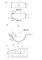
次に、発明の実施の形態を説明する。なお、図1はすべり軸受1の正面図であり、図面の上下を上下方向、図面の手前方向及び奥方向を軸方向(前後方向)とする。 Next, embodiments of the invention will be described. FIG. 1 is a front view of the sliding bearing 1, and the vertical direction in the drawing is the vertical direction, and the front direction and the back direction in the drawing are axial directions (front-rear direction).
まず、第一の実施形態に係るすべり軸受1を構成する半割部材2について図1及び図2を用いて説明する。
すべり軸受1は円筒状の部材であり、図1に示すように、エンジンのクランクシャフト11のすべり軸受構造に適用される。すべり軸受1は、二つの半割部材2・2で構成されている。二つの半割部材2・2は、円筒を軸方向と平行に二分割した形状であり、断面が半円状となるように形成されている。本実施形態においては、半割部材2・2は上下に配置されており、左右に合わせ面が配置されている。クランクシャフト11をすべり軸受1で軸支する場合、所定の隙間が形成され、この隙間に対し図示せぬ油路から潤滑油が供給される。
First, the
The slide bearing 1 is a cylindrical member and is applied to a slide bearing structure of an
図2(a)においては、上側および下側の半割部材2を示している。なお、本実施形態においては、クランクシャフト11の回転方向を図1の矢印に示すように正面視時計回り方向とする。また、軸受角度ωは、図2(b)における右端の位置を0度とし、図2(b)において、反時計回り方向を正とする。すなわち、図2(b)において、左端の位置の軸受角度ωが180度となり、下端の位置の軸受角度ωが270度となるように定義する。
In FIG. 2A, the upper and
上側の半割部材2の内周には円周方向に溝が設けられており、中心に円形の孔が設けられている。また、上側の半割部材2の左右に合わせ面が配置されている。
On the inner periphery of the
下側の半割部材2の内周の当接面において、その軸方向の端部に細溝3が形成されている。
細溝3は下側の半割部材2に設けられる。本実施形態においては、細溝3は軸方向に並列して二本設けられている。詳細には、細溝3は、クランクシャフト11の回転方向下流側端部3a(軸受角度ωがω0)から軸受角度ωが正となる方向(反時計回り方向)に向けて円周方向に設けられる。なお、下側の半割部材2においては、図2(b)の右側の合わせ面が回転方向上流側合わせ面、図2(b)の左側の合わせ面が回転方向下流側合わせ面となる。
A
The
細溝3の回転方向下流側端部3aは、クランクシャフト11の回転方向下流側合わせ面に近接しており、回転方向下流側端部3aと回転方向下流側合わせ面とは連通することなく設けられている。
細溝3の回転方向下流側端部3bは、軸受角度ωがω1となる位置に設けられている。
細溝3の長さlは、回転方向下流側端部3aから回転方向上流側端部3bまでの長さに形成したものである。
細溝3の軸方向の幅は、図2(c)に示すように、wとなるように形成されている。
また、細溝3の底面からすべり軸受の軸との当接面までの高さdは、半割部材2の外周面から当接面までの高さDよりも短くなるように形成されている。ここで、半割部材2の外周面から当接面までの高さDとは、半割部材2の肉厚であり、本実施形態においては、Dは1〜10mmである。
The rotation direction
The
The length 1 of the
The width of the
Further, the height d from the bottom surface of the
また、細溝3の軸方向外側面を形成する周縁部2aは、細溝3の底面からの高さhが、細溝3の底面からすべり軸受の軸との当接面までの高さdよりも低くなるように形成したよりも低くなるように形成されている。すなわち、軸方向外側の周縁部2aが周囲のクランクシャフト11との当接面よりも一段低くなるように形成されている。
また、細溝3の底面からの高さhは0.05mm以上となるように形成している。
Further, the
Further, the height h from the bottom surface of the
周縁部2aが周囲のクランクシャフト11との当接面よりも一段低くなるように形成されていることにより、クランクシャフト11が傾いて軸方向片側端部にのみ接触する状態(片当りする状態)となったときに、周縁部2aとクランクシャフト11との接触機会を減らすことができるため、周縁部2aの損傷を防止することができる。また、周縁部2aの一段低くなった部分の長さは、細溝3の長さlよりも短くなるように形成されている。
The
また、周縁部2aが周囲の当接面よりも一段低くなるように形成されていることにより、すべり軸受1の軸方向端部における隙間が広がり、吸い戻し油量が増えてトータルの流出油量が低減される。
Further, since the
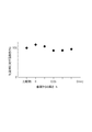
図3は、周縁部の細溝底面からの高さと、比較例に対するトータルの流出油量の割合との関係を示すグラフである。最も左の点は比較例である細溝を設けない場合のすべり軸受のトータルの流出油量であり、本実施形態に係る細溝3及び周縁部2aを設けたすべり軸受1のトータルの流出油量の比較例に対する割合を示したものである。
FIG. 3 is a graph showing the relationship between the height of the peripheral edge from the bottom surface of the narrow groove and the ratio of the total amount of oil spilled with respect to the comparative example. The leftmost point is the total spilled oil amount of the sliding bearing when no narrow groove is provided as a comparative example, and the total spilled oil of the sliding bearing 1 provided with the
図3の右方向に向かうにしたがって、周縁部2aの細溝3の底面からの高さhが大きくなる。ここで、周縁部2aの細溝3の底面からの高さhを0とした場合には、比較例に対するトータルの流出油量の割合が100%を超える。言い換えれば、周縁部2aの細溝3の底面からの高さhを0とした場合には、細溝を設けない場合に比べて、トータルの流出油量が多くなってしまうものである。
The height h from the bottom surface of the
これに対して、周縁部2aの細溝3の底面からの高さhを0.05mmとした場合には、比較例に対するトータルの流出油量の割合が100%よりも小さくなる。
また、周縁部2aの細溝3の底面からの高さhを0.05mmよりも大きくした場合には、周縁部2aの細溝3の底面からの高さhを0.05mmとした場合と比較すると大きくなるが、比較例に対するトータルの流出油量の割合は100%よりも小さくなる。
On the other hand, when the height h from the bottom surface of the
Further, when the height h of the
また、周縁部2aの細溝3の底面からの高さhはすべり軸受1のクランクシャフト11との当接面よりも小さくするように構成している。周縁部2aの細溝3の底面からの高さhが当接面よりも高くなると、摺動抵抗が増加してしまうため、摺動性能が低下する。そこで、周縁部2aの細溝3の底面からの高さhはすべり軸受1のクランクシャフト11との当接面よりも小さくするように構成している。
Further, the height h of the
このように、周縁部2aの細溝3の底面からの高さhを0.05mm以上であってすべり軸受1のクランクシャフト11との当接面よりも小さくなるように構成することで、例えば冷間始動時において軸受内面より漏れた油の再循環を促進し、冷間時油膜を早期昇温させ、フリクション低減効果を得ることができ、トータルの流出油量を抑えることができる。
In this way, by configuring the height h of the
以上のように、すべり軸受1は、円筒を軸方向と平行に二分割した半割部材2・2を上下に配置したすべり軸受1であって、下側の半割部材2の軸方向端部に円周方向に細溝3を設け、細溝3の軸方向外側に周縁部2aを形成し、周縁部2aの細溝3底面からの高さhを0.05mm以上であって、すべり軸受1のクランクシャフト11との当接面よりも低くなるように形成したものである。
このように構成することにより、例えば冷間始動時においてフリクション低減効果を得ることができ、トータルの流出油量を抑えることができる。
As described above, the sliding bearing 1 is the sliding bearing 1 in which the
With this configuration, for example, a friction reduction effect can be obtained during cold start, and the total amount of oil spilled can be suppressed.
1 すべり軸受
2 半割部材
2a 周縁部
3 細溝
11 クランクシャフト(軸)
DESCRIPTION OF SYMBOLS 1
Claims (1)
Priority Applications (2)
| Application Number | Priority Date | Filing Date | Title |
|---|---|---|---|
| JP2015246780A JP2019031981A (en) | 2015-12-17 | 2015-12-17 | Slide bearing |
| PCT/JP2016/087534 WO2017104795A1 (en) | 2015-12-17 | 2016-12-16 | Slide bearing |
Applications Claiming Priority (1)
| Application Number | Priority Date | Filing Date | Title |
|---|---|---|---|
| JP2015246780A JP2019031981A (en) | 2015-12-17 | 2015-12-17 | Slide bearing |
Publications (1)
| Publication Number | Publication Date |
|---|---|
| JP2019031981A true JP2019031981A (en) | 2019-02-28 |
Family
ID=59056737
Family Applications (1)
| Application Number | Title | Priority Date | Filing Date |
|---|---|---|---|
| JP2015246780A Pending JP2019031981A (en) | 2015-12-17 | 2015-12-17 | Slide bearing |
Country Status (2)
| Country | Link |
|---|---|
| JP (1) | JP2019031981A (en) |
| WO (1) | WO2017104795A1 (en) |
Families Citing this family (1)
| Publication number | Priority date | Publication date | Assignee | Title |
|---|---|---|---|---|
| JP2019211001A (en) * | 2018-06-04 | 2019-12-12 | 大豊工業株式会社 | Slide bearing |
Citations (3)
| Publication number | Priority date | Publication date | Assignee | Title |
|---|---|---|---|---|
| JP2014224601A (en) * | 2013-04-26 | 2014-12-04 | 大豊工業株式会社 | Slide bearing |
| JP2015137709A (en) * | 2014-01-22 | 2015-07-30 | 大豊工業株式会社 | slide bearing |
| JP2015197215A (en) * | 2014-04-03 | 2015-11-09 | 大豊工業株式会社 | slide bearing |
-
2015
- 2015-12-17 JP JP2015246780A patent/JP2019031981A/en active Pending
-
2016
- 2016-12-16 WO PCT/JP2016/087534 patent/WO2017104795A1/en active Application Filing
Patent Citations (3)
| Publication number | Priority date | Publication date | Assignee | Title |
|---|---|---|---|---|
| JP2014224601A (en) * | 2013-04-26 | 2014-12-04 | 大豊工業株式会社 | Slide bearing |
| JP2015137709A (en) * | 2014-01-22 | 2015-07-30 | 大豊工業株式会社 | slide bearing |
| JP2015197215A (en) * | 2014-04-03 | 2015-11-09 | 大豊工業株式会社 | slide bearing |
Also Published As
| Publication number | Publication date |
|---|---|
| WO2017104795A1 (en) | 2017-06-22 |
Similar Documents
| Publication | Publication Date | Title |
|---|---|---|
| JP6096689B2 (en) | Plain bearing | |
| JP5837896B2 (en) | Plain bearing | |
| JP6185853B2 (en) | Plain bearing | |
| WO2016136998A1 (en) | Slide bearing | |
| JP6134636B2 (en) | Plain bearing | |
| JP5914383B2 (en) | Plain bearing | |
| JP2016161016A (en) | Manufacturing method of slide bearing, and slide bearing | |
| JP2019031981A (en) | Slide bearing | |
| JP6216226B2 (en) | Plain bearing | |
| JP6536774B2 (en) | Slide bearing | |
| JP6314103B2 (en) | Plain bearing | |
| JP6323833B2 (en) | Plain bearing | |
| WO2016136993A1 (en) | Sliding bearing | |
| JP6390852B2 (en) | Plain bearing | |
| JP2016161018A5 (en) | ||
| JP6399576B2 (en) | Plain bearing | |
| JP6624559B2 (en) | Plain bearing | |
| JP6166064B2 (en) | Plain bearing | |
| JP6541144B2 (en) | Slide bearing | |
| JP2017110765A (en) | Slide bearing | |
| JP2017110764A (en) | Slide bearing | |
| JP2016161011A (en) | Slide bearing | |
| JP2017110761A (en) | Slide bearing | |
| JP2017110763A (en) | Slide bearing | |
| JP2016161014A (en) | Manufacturing method of slide bearing, and slide bearing |
Legal Events
| Date | Code | Title | Description |
|---|---|---|---|
| A621 | Written request for application examination |
Free format text: JAPANESE INTERMEDIATE CODE: A621 Effective date: 20180720 |
|
| A131 | Notification of reasons for refusal |
Free format text: JAPANESE INTERMEDIATE CODE: A131 Effective date: 20190604 |
|
| A02 | Decision of refusal |
Free format text: JAPANESE INTERMEDIATE CODE: A02 Effective date: 20191210 |