JP2016161016A - Manufacturing method of slide bearing, and slide bearing - Google Patents
Manufacturing method of slide bearing, and slide bearing Download PDFInfo
- Publication number
- JP2016161016A JP2016161016A JP2015039116A JP2015039116A JP2016161016A JP 2016161016 A JP2016161016 A JP 2016161016A JP 2015039116 A JP2015039116 A JP 2015039116A JP 2015039116 A JP2015039116 A JP 2015039116A JP 2016161016 A JP2016161016 A JP 2016161016A
- Authority
- JP
- Japan
- Prior art keywords
- narrow groove
- lining layer
- manufacturing
- slide bearing
- layer
- Prior art date
- Legal status (The legal status is an assumption and is not a legal conclusion. Google has not performed a legal analysis and makes no representation as to the accuracy of the status listed.)
- Pending
Links
Images


Classifications
-
- F—MECHANICAL ENGINEERING; LIGHTING; HEATING; WEAPONS; BLASTING
- F16—ENGINEERING ELEMENTS AND UNITS; GENERAL MEASURES FOR PRODUCING AND MAINTAINING EFFECTIVE FUNCTIONING OF MACHINES OR INSTALLATIONS; THERMAL INSULATION IN GENERAL
- F16C—SHAFTS; FLEXIBLE SHAFTS; ELEMENTS OR CRANKSHAFT MECHANISMS; ROTARY BODIES OTHER THAN GEARING ELEMENTS; BEARINGS
- F16C33/00—Parts of bearings; Special methods for making bearings or parts thereof
- F16C33/02—Parts of sliding-contact bearings
- F16C33/04—Brasses; Bushes; Linings
- F16C33/06—Sliding surface mainly made of metal
- F16C33/14—Special methods of manufacture; Running-in
-
- F—MECHANICAL ENGINEERING; LIGHTING; HEATING; WEAPONS; BLASTING
- F16—ENGINEERING ELEMENTS AND UNITS; GENERAL MEASURES FOR PRODUCING AND MAINTAINING EFFECTIVE FUNCTIONING OF MACHINES OR INSTALLATIONS; THERMAL INSULATION IN GENERAL
- F16C—SHAFTS; FLEXIBLE SHAFTS; ELEMENTS OR CRANKSHAFT MECHANISMS; ROTARY BODIES OTHER THAN GEARING ELEMENTS; BEARINGS
- F16C17/00—Sliding-contact bearings for exclusively rotary movement
- F16C17/02—Sliding-contact bearings for exclusively rotary movement for radial load only
- F16C17/022—Sliding-contact bearings for exclusively rotary movement for radial load only with a pair of essentially semicircular bearing sleeves
-
- F—MECHANICAL ENGINEERING; LIGHTING; HEATING; WEAPONS; BLASTING
- F16—ENGINEERING ELEMENTS AND UNITS; GENERAL MEASURES FOR PRODUCING AND MAINTAINING EFFECTIVE FUNCTIONING OF MACHINES OR INSTALLATIONS; THERMAL INSULATION IN GENERAL
- F16C—SHAFTS; FLEXIBLE SHAFTS; ELEMENTS OR CRANKSHAFT MECHANISMS; ROTARY BODIES OTHER THAN GEARING ELEMENTS; BEARINGS
- F16C33/00—Parts of bearings; Special methods for making bearings or parts thereof
- F16C33/02—Parts of sliding-contact bearings
- F16C33/04—Brasses; Bushes; Linings
- F16C33/046—Brasses; Bushes; Linings divided or split, e.g. half-bearings or rolled sleeves
-
- F—MECHANICAL ENGINEERING; LIGHTING; HEATING; WEAPONS; BLASTING
- F16—ENGINEERING ELEMENTS AND UNITS; GENERAL MEASURES FOR PRODUCING AND MAINTAINING EFFECTIVE FUNCTIONING OF MACHINES OR INSTALLATIONS; THERMAL INSULATION IN GENERAL
- F16C—SHAFTS; FLEXIBLE SHAFTS; ELEMENTS OR CRANKSHAFT MECHANISMS; ROTARY BODIES OTHER THAN GEARING ELEMENTS; BEARINGS
- F16C33/00—Parts of bearings; Special methods for making bearings or parts thereof
- F16C33/02—Parts of sliding-contact bearings
- F16C33/04—Brasses; Bushes; Linings
- F16C33/06—Sliding surface mainly made of metal
- F16C33/10—Construction relative to lubrication
- F16C33/1025—Construction relative to lubrication with liquid, e.g. oil, as lubricant
- F16C33/103—Construction relative to lubrication with liquid, e.g. oil, as lubricant retained in or near the bearing
-
- F—MECHANICAL ENGINEERING; LIGHTING; HEATING; WEAPONS; BLASTING
- F16—ENGINEERING ELEMENTS AND UNITS; GENERAL MEASURES FOR PRODUCING AND MAINTAINING EFFECTIVE FUNCTIONING OF MACHINES OR INSTALLATIONS; THERMAL INSULATION IN GENERAL
- F16C—SHAFTS; FLEXIBLE SHAFTS; ELEMENTS OR CRANKSHAFT MECHANISMS; ROTARY BODIES OTHER THAN GEARING ELEMENTS; BEARINGS
- F16C33/00—Parts of bearings; Special methods for making bearings or parts thereof
- F16C33/02—Parts of sliding-contact bearings
- F16C33/04—Brasses; Bushes; Linings
- F16C33/06—Sliding surface mainly made of metal
- F16C33/10—Construction relative to lubrication
- F16C33/1025—Construction relative to lubrication with liquid, e.g. oil, as lubricant
- F16C33/106—Details of distribution or circulation inside the bearings, e.g. details of the bearing surfaces to affect flow or pressure of the liquid
- F16C33/1065—Grooves on a bearing surface for distributing or collecting the liquid
-
- F—MECHANICAL ENGINEERING; LIGHTING; HEATING; WEAPONS; BLASTING
- F16—ENGINEERING ELEMENTS AND UNITS; GENERAL MEASURES FOR PRODUCING AND MAINTAINING EFFECTIVE FUNCTIONING OF MACHINES OR INSTALLATIONS; THERMAL INSULATION IN GENERAL
- F16C—SHAFTS; FLEXIBLE SHAFTS; ELEMENTS OR CRANKSHAFT MECHANISMS; ROTARY BODIES OTHER THAN GEARING ELEMENTS; BEARINGS
- F16C33/00—Parts of bearings; Special methods for making bearings or parts thereof
- F16C33/02—Parts of sliding-contact bearings
- F16C33/04—Brasses; Bushes; Linings
- F16C33/06—Sliding surface mainly made of metal
- F16C33/10—Construction relative to lubrication
- F16C33/1025—Construction relative to lubrication with liquid, e.g. oil, as lubricant
- F16C33/106—Details of distribution or circulation inside the bearings, e.g. details of the bearing surfaces to affect flow or pressure of the liquid
- F16C33/107—Grooves for generating pressure
-
- F—MECHANICAL ENGINEERING; LIGHTING; HEATING; WEAPONS; BLASTING
- F16—ENGINEERING ELEMENTS AND UNITS; GENERAL MEASURES FOR PRODUCING AND MAINTAINING EFFECTIVE FUNCTIONING OF MACHINES OR INSTALLATIONS; THERMAL INSULATION IN GENERAL
- F16C—SHAFTS; FLEXIBLE SHAFTS; ELEMENTS OR CRANKSHAFT MECHANISMS; ROTARY BODIES OTHER THAN GEARING ELEMENTS; BEARINGS
- F16C9/00—Bearings for crankshafts or connecting-rods; Attachment of connecting-rods
- F16C9/02—Crankshaft bearings
-
- F—MECHANICAL ENGINEERING; LIGHTING; HEATING; WEAPONS; BLASTING
- F16—ENGINEERING ELEMENTS AND UNITS; GENERAL MEASURES FOR PRODUCING AND MAINTAINING EFFECTIVE FUNCTIONING OF MACHINES OR INSTALLATIONS; THERMAL INSULATION IN GENERAL
- F16C—SHAFTS; FLEXIBLE SHAFTS; ELEMENTS OR CRANKSHAFT MECHANISMS; ROTARY BODIES OTHER THAN GEARING ELEMENTS; BEARINGS
- F16C2240/00—Specified values or numerical ranges of parameters; Relations between them
- F16C2240/30—Angles, e.g. inclinations
-
- F—MECHANICAL ENGINEERING; LIGHTING; HEATING; WEAPONS; BLASTING
- F16—ENGINEERING ELEMENTS AND UNITS; GENERAL MEASURES FOR PRODUCING AND MAINTAINING EFFECTIVE FUNCTIONING OF MACHINES OR INSTALLATIONS; THERMAL INSULATION IN GENERAL
- F16C—SHAFTS; FLEXIBLE SHAFTS; ELEMENTS OR CRANKSHAFT MECHANISMS; ROTARY BODIES OTHER THAN GEARING ELEMENTS; BEARINGS
- F16C2240/00—Specified values or numerical ranges of parameters; Relations between them
- F16C2240/40—Linear dimensions, e.g. length, radius, thickness, gap
- F16C2240/42—Groove sizes
Landscapes
- Engineering & Computer Science (AREA)
- General Engineering & Computer Science (AREA)
- Mechanical Engineering (AREA)
- Chemical & Material Sciences (AREA)
- Oil, Petroleum & Natural Gas (AREA)
- Sliding-Contact Bearings (AREA)
- Shafts, Cranks, Connecting Bars, And Related Bearings (AREA)
Abstract
Description
本発明は、すべり軸受の製造方法の技術に関し、円筒を軸方向と平行に二分割した半割部材を上下に配置したすべり軸受の製造方法の技術に関する。 The present invention relates to a technology of a sliding bearing manufacturing method, and more particularly to a technology of a sliding bearing manufacturing method in which a half member in which a cylinder is divided into two in parallel with an axial direction is vertically arranged.
従来、エンジンのクランクシャフトを軸支するための軸受であって、円筒形状を二分割した二つの部材を合わせる半割れ構造のすべり軸受が公知となっているが、冷間時に油の粘度が高いためフリクションが大きいという課題がある。そこで、前記軸受の軸方向両端部に、逃げ部分(細溝)を形成した軸受が公知となっている(例えば、特許文献1参照)。 Conventionally, a bearing for supporting an engine crankshaft and having a half-crack structure in which two members divided into two cylindrical shapes are combined is known, but the viscosity of oil is high when cold. Therefore, there is a problem that friction is large. Therefore, a bearing in which relief portions (narrow grooves) are formed at both axial ends of the bearing is known (for example, see Patent Document 1).
しかし、従来の細溝を形成した軸受では、油の引き込み量増加と軸方向両端部からの油の漏れ量抑制を両立することができず、更なるフリクション低減効果が期待できなかった。 However, in a conventional bearing having a narrow groove, it is impossible to achieve both an increase in the amount of oil drawn and a suppression of the amount of oil leakage from both ends in the axial direction, and a further effect of reducing friction cannot be expected.
そこで、本発明は係る課題に鑑み、総和の流出油量を抑えることができ、更なるフリクション低減効果を得ることができるすべり軸受を提供する。 Then, in view of the subject which concerns, this invention provides the slide bearing which can suppress the sum total amount of spilled oil, and can acquire the further friction reduction effect.
本発明の解決しようとする課題は以上の如くであり、次にこの課題を解決するための手段を説明する。 The problem to be solved by the present invention is as described above. Next, means for solving the problem will be described.
即ち、請求項1においては、円筒を軸方向と平行に二分割し、金属層と、前記金属層の内周面に設けられたライニング層とを有する半割部材を上下に配置したすべり軸受の製造方法であって、前記製造方法は、前記下側の半割部材の軸方向端部に、回転方向下流側において円周方向に細溝を設ける第一の工程を有し、前記第一の工程において、前記細溝の深さを、前記ライニング層の厚さから前記ライニング層の厚さの公差を引いた長さよりも長くなるように形成したものである。 That is, according to the first aspect of the present invention, there is provided a sliding bearing in which a cylinder is divided into two parallel to the axial direction, and a half member having a metal layer and a lining layer provided on an inner peripheral surface of the metal layer is arranged vertically. In the manufacturing method, the manufacturing method includes a first step of providing a narrow groove in a circumferential direction on the downstream side in the rotation direction at an axial end portion of the lower half member. In the step, the depth of the narrow groove is formed to be longer than a length obtained by subtracting a tolerance of the thickness of the lining layer from the thickness of the lining layer.
請求項2においては、前記製造方法は、前記下側の半割部材の軸方向端部であって前記細溝の軸方向外側に周縁部を設ける第二の工程を有し、前記第二の工程において、前記周縁部の内周面を、前記細溝の底面よりも内周側に形成したものである。 According to a second aspect of the present invention, the manufacturing method includes a second step of providing a peripheral edge portion on the axially outer side of the narrow groove at the axial end portion of the lower half member. In the step, the inner peripheral surface of the peripheral edge is formed on the inner peripheral side with respect to the bottom surface of the narrow groove.
請求項3においては、請求項1または請求項2の製造方法によって製造されたすべり軸受である。 According to a third aspect of the present invention, the slide bearing is manufactured by the manufacturing method according to the first or second aspect.
本発明の効果として、以下に示すような効果を奏する。 As effects of the present invention, the following effects can be obtained.
すなわち、油膜圧力の発生を妨げない程度の細溝を設けることで、摺動面積を減らしつつ、フリクション低減効果を得ることができ、かつ、総和の流出油量を抑えることができる。また、細溝の深さを、ライニング層の厚さから前記ライニング層の厚さの公差を引いた長さよりも長くなるように形成したことにより、ライニング層及び金属層に細溝を設けることができるので、細溝の吸い戻し油量が増加し、総和の流出油量を抑えることができる。 That is, by providing a narrow groove that does not hinder the generation of oil film pressure, it is possible to obtain a friction reduction effect while reducing the sliding area, and to suppress the total amount of oil spilled. Further, by forming the depth of the narrow groove to be longer than the length obtained by subtracting the tolerance of the thickness of the lining layer from the thickness of the lining layer, the narrow groove can be provided in the lining layer and the metal layer. As a result, the amount of oil sucked back in the narrow groove is increased, and the total amount of oil spilled can be suppressed.
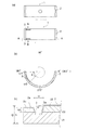
次に、発明の実施の形態を説明する。なお、図1はすべり軸受1の正面図であり、画面の上下を上下方向、画面の手前方向及び奥方向を軸方向(前後方向)とする。 Next, embodiments of the invention will be described. FIG. 1 is a front view of the sliding bearing 1, where the top and bottom of the screen is the vertical direction, and the front and back directions of the screen are the axial directions (front and back directions).
まず、本発明の実施形態に係るすべり軸受1を構成する半割部材2について図1及び図2を用いて説明する。
すべり軸受1は円筒状の部材であり、図1に示すように、エンジンのクランクシャフト11のすべり軸受構造に適用される。すべり軸受1は、二つの半割部材2・2で構成されている。二つの半割部材2・2は、円筒を軸方向と平行に二分割した形状であり、断面が半円状となるように形成されている。本実施形態においては、半割部材2・2は上下に配置されており、左右に合わせ面が配置されている。クランクシャフト11をすべり軸受1で軸支する場合、所定の隙間が形成され、この隙間に対し図示せぬ油路から潤滑油が供給される。
First, the
The slide bearing 1 is a cylindrical member and is applied to a slide bearing structure of an
図2(a)においては、上側および下側の半割部材2を示している。なお、本実施形態においては、クランクシャフト11の回転方向を図1の矢印に示すように正面視時計回り方向とする。また、軸受角度ωは、図2(b)における右端の位置を0度とし、図2(b)において、反時計回り方向を正とする。すなわち、図2(b)において、左端の位置の軸受角度ωが180度となり、下端の位置の軸受角度ωが270度となるように定義する。
In FIG. 2A, the upper and
上側の半割部材2の内周には円周方向に溝が設けられており、中心に円形の孔が設けられている。また、上側の半割部材2の左右に合わせ面が配置されている。半割部材2は、図2(c)に示すように、金属層21、ライニング層22及びコーティング層23を有する。
下側の半割部材2の内周において、その軸方向の端部に細溝3が形成されている。
また、細溝3の軸方向外側面を形成する周縁部2aは、半割部材2の外周面からの高さhが、半割部材2の外周面から当接面までの高さDよりも低くなるように形成されている。すなわち、軸方向外側の周縁部2aが周囲のクランクシャフト11との当接面よりも一段低くなるように形成されている。
On the inner periphery of the
On the inner periphery of the
Further, the
細溝3について図2(b)及び図2(c)を用いて説明する。
細溝3は下側の半割部材2に設けられる。本実施形態においては、細溝3は軸方向に並列して二本設けられている。詳細には、細溝3は、クランクシャフト11の回転方向下流側合わせ面(軸受角度ωが180度)と離間した位置(軸受角度ωがω1)から軸受角度ωが正となる方向(反時計回り方向)に向けて、軸受角度ω2まで円周方向に設けられる。下側の半割部材2においては、図2(b)の右側の合わせ面が回転方向上流側合わせ面、図2(b)の左側の合わせ面が回転方向下流側合わせ面となる。
細溝3の幅は、図2(c)に示すように、wとなるように形成されている。
また、細溝3の深さdは、半割部材2の外周面から当接面までの高さDよりも短くなるように形成されている。
The
The
As shown in FIG. 2C, the
Further, the depth d of the
また、周縁部2aが細溝3の底面3aよりも一段高くなるように形成されていることにより、摺動面から軸方向端部に漏れる油や吸い戻した油が再度漏れないための壁となり、漏れ油量を抑制できる。これにより、特に冷間時の引き込み油量が増加し、早期昇温による低フリクション効果を増大することができる。
Further, since the
また、周縁部2aが周囲のクランクシャフト11との当接面よりも一段低くなるように形成されていることにより、クランクシャフト11が傾いて軸方向片側端部にのみ接触する状態(片当りする状態)となったときに、周縁部2aとクランクシャフト11との接触機会を減らすことができるため、周縁部2aの損傷を防止することができる。
Further, since the
本実施形態に係る細溝3を設けたことにより、FMEP軽減量が増加する。特に、エンジン回転数が低い領域において、FMEP軽減量が増加する。ここで、FMEPとは、フリクションの傾向を見るための値であり、FMEP軽減量が増加するとフリクションが低減する。例えば、エンジンが冷間始動する際などにおいて、FMEP軽減量が増加し、フリクションが低減する。
By providing the
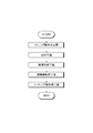
次に、すべり軸受1を構成する下側の半割部材2の製造方法について、図3を用いて説明する。
下側の半割部材2の製造方法は、金属層21にライニング層22を貼設するライニング層形成工程と、ライニング層22及び金属層21を半円形状に成形する成形工程と、細溝3を形成する第一の工程である細溝形成工程と、周縁部2aを形成する第二の工程である周縁部形成工程と、ライニング層22の表面に図4に示すコーティング層23を形成するコーティング層形成工程と、を備える。以下に、各工程について具体的に説明する。
Next, the manufacturing method of the
The manufacturing method of the
ライニング層形成工程においては、金属層21にライニング層22を貼設する。より詳しくは、金属層21及びライニング層22に圧延処理を加えることにより、金属層21にライニング層22を貼設する。ここで、金属層21とは、金属からなる素材で構成されており、例えば鉄系の材料からなる素材で構成されている。また、ライニング層22は、金属層21よりも硬度が低い金属からなる素材で構成されており、例えばアルミニウム系の材料からなる素材で構成されている。
In the lining layer forming step, the
次に、成形工程においては、金属層21及びライニング層22を半円形状に成形する。より詳しくは、金属層21及びライニング層22をプレス成型することにより半円形状に成形する。
Next, in the forming step, the
次に、細溝形成工程においては、細溝3を形成する。さらに、周縁部形成工程においては、周縁部2aを形成する。
Next, the
本実施形態に係る細溝3及び周縁部2aを形成する方法の一例として、細溝3及び周縁部2aを切削加工により形成する方法について説明する。
切削加工は、円鋸のような刃具によって行われる。細溝形成工程においては、細溝3の深さdを、ライニング層22の厚さh1から、ライニング層22の厚さの公差a1を引いた長さよりも長くなるように形成する。例えば、ライニング層22の厚さをh1、ライニング層22の厚さの公差をa1、細溝の深さをd、としたとき、細溝3の深さdは、d>h1−a1となるように構成される。
このように構成することにより、細溝3の深さdが、ライニング層22の厚さh1よりも長くなるため、細溝3は、ライニング層22から金属層21にわたって形成される。このため、細溝3の深さdの長さを十分に大きくとることができるため、吸い戻し油量が増加し、総和の流出油量を抑えることができる。
As an example of a method for forming the
Cutting is performed with a cutting tool such as a circular saw. In the narrow groove forming step, the depth d of the
With this configuration, the depth d of the
また、周縁部形成工程においては、周縁部2aの内周面2cを、細溝3の底面3aよりも内周側に形成したため、周縁部2aもライニング層22内に形成される。これにより、周縁部2aを形成する際に、刃具が金属層21に接触することが無くなるため、刃具の長寿命化を図ることができる。
In the peripheral edge forming step, the inner
次に、コーティング層形成工程においては、ライニング層22の表面(内周面)にコーティング層23を形成する。ここでコーティング層23とは、軟質金属や樹脂系の材料からなる素材で構成されている。
Next, in the coating layer forming step, the
コーティング層23は、ライニング層22の内周面上に塗布されることにより形成される。この際、コーティング層23は、図2(c)に示すように、細溝3の軸方向内側端部を覆うように形成されており、より詳しくは、細溝3の軸方向内側の側面の中途部まで塗布されている。このように構成することにより、細溝3の軸方向内側端部をコーティング層23で覆うことにより、クランクシャフト11が傾いて軸方向片側端部にのみ接触する状態(片当りする状態)となったときに、細溝3の軸方向内側端部とクランクシャフト11との摩擦を軽減させることができる。
The
また、図4に示すように、コーティング層23は、細溝3全体を覆うように形成することもできる。このように構成することにより、クランクシャフト11が傾いて軸方向片側端部にのみ接触する状態(片当りする状態)となったときに、細溝3の軸方向内側端部及び軸方向外側端部と、クランクシャフト11との摩擦を軽減させることができる。
Moreover, as shown in FIG. 4, the
以上のように、円筒を軸方向と平行に二分割し、金属層21と、金属層21の内周面に設けられたライニング層22とを有する半割部材2・2を上下に配置したすべり軸受の製造方法であって、前記製造方法は、下側の半割部材2の軸方向端部に、回転方向下流側において円周方向に細溝3を設ける細溝形成工程(第一の工程)を有し、細溝形成工程において、細溝3の深さdを、ライニング層22の厚さh1から、ライニング層22の厚さの公差a1を引いた長さよりも長くなるように形成したものである。
このように構成することにより、油膜圧力の発生を妨げない程度の細溝3を設けることで、摺動面積を減らしつつ、フリクション低減効果を得ることができ、かつ、総和の流出油量を抑えることができる。また、細溝3の深さdを、ライニング層22の厚さh1から、ライニング層22の厚さの公差a1を引いた長さよりも長くなるように形成したことにより、ライニング層22及び金属層21に細溝3を設けることができるので、細溝3の吸い戻し油量が増加し、総和の流出油量を抑えることができる。
As described above, the cylinder is divided into two parallel to the axial direction, and the
With this configuration, by providing the
また、下側の半割部材2の軸方向端部であって細溝3の軸方向外側に周縁部を設ける周縁部形成工程(第二の工程)を有し、周縁部形成工程において、周縁部2aの内周面2cを、細溝3の底面3aよりも内周側に形成したものである。
このように構成することにより、円鋸などの刃具により周縁部2を形成する際には、ライニング層22よりも硬度の高い金属層21に刃具が当るのを防ぐことができるので、刃具の寿命が長くなる。
Moreover, it has the peripheral part formation process (2nd process) which provides a peripheral part in the axial direction edge part of the
With this configuration, when the
1 すべり軸受
2 半割部材
2a 周縁部
3 細溝
11 クランクシャフト
21 金属層
22 ライニング層
23 コーティング層
DESCRIPTION OF SYMBOLS 1
Claims (3)
前記製造方法は、前記下側の半割部材の軸方向端部に、回転方向下流側において円周方向に細溝を設ける第一の工程を有し、
前記第一の工程において、前記細溝の深さを、前記ライニング層の厚さから前記ライニング層の厚さの公差を引いた長さよりも長くなるように形成した
ことを特徴とするすべり軸受の製造方法。 A method of manufacturing a plain bearing in which a cylinder is divided into two parallel to an axial direction, and a half member having a metal layer and a lining layer provided on an inner peripheral surface of the metal layer is arranged vertically,
The manufacturing method includes a first step of providing a narrow groove in the circumferential direction on the downstream side in the rotational direction at the axial end of the lower half member,
In the first step, the depth of the narrow groove is formed to be longer than a length obtained by subtracting a tolerance of the thickness of the lining layer from the thickness of the lining layer. Production method.
前記第二の工程において、
前記周縁部の内周面を、前記細溝の底面よりも内周側に形成した
ことを特徴とする請求項1に記載のすべり軸受の製造方法。 The manufacturing method includes a second step of providing a peripheral edge on the axially outer side of the narrow groove at the axial end of the lower half member.
In the second step,
The method for manufacturing a plain bearing according to claim 1, wherein an inner peripheral surface of the peripheral edge portion is formed on an inner peripheral side with respect to a bottom surface of the narrow groove.
Priority Applications (6)
| Application Number | Priority Date | Filing Date | Title |
|---|---|---|---|
| JP2015039116A JP2016161016A (en) | 2015-02-27 | 2015-02-27 | Manufacturing method of slide bearing, and slide bearing |
| CN201680012098.XA CN107250576A (en) | 2015-02-27 | 2016-02-26 | The manufacture method and sliding bearing of sliding bearing |
| EP16755740.4A EP3263924A4 (en) | 2015-02-27 | 2016-02-26 | Method for producing slide bearing, and slide bearing |
| PCT/JP2016/055951 WO2016136996A1 (en) | 2015-02-27 | 2016-02-26 | Method for producing slide bearing, and slide bearing |
| KR1020177026133A KR20170118186A (en) | 2015-02-27 | 2016-02-26 | METHOD FOR MANUFACTURING SLIDE BEARING AND SLIDE BEARING |
| US15/553,738 US20180119739A1 (en) | 2015-02-27 | 2016-02-26 | Sliding bearing manufacturing method and sliding bearing |
Applications Claiming Priority (1)
| Application Number | Priority Date | Filing Date | Title |
|---|---|---|---|
| JP2015039116A JP2016161016A (en) | 2015-02-27 | 2015-02-27 | Manufacturing method of slide bearing, and slide bearing |
Publications (2)
| Publication Number | Publication Date |
|---|---|
| JP2016161016A true JP2016161016A (en) | 2016-09-05 |
| JP2016161016A5 JP2016161016A5 (en) | 2018-04-05 |
Family
ID=56789587
Family Applications (1)
| Application Number | Title | Priority Date | Filing Date |
|---|---|---|---|
| JP2015039116A Pending JP2016161016A (en) | 2015-02-27 | 2015-02-27 | Manufacturing method of slide bearing, and slide bearing |
Country Status (6)
| Country | Link |
|---|---|
| US (1) | US20180119739A1 (en) |
| EP (1) | EP3263924A4 (en) |
| JP (1) | JP2016161016A (en) |
| KR (1) | KR20170118186A (en) |
| CN (1) | CN107250576A (en) |
| WO (1) | WO2016136996A1 (en) |
Cited By (3)
| Publication number | Priority date | Publication date | Assignee | Title |
|---|---|---|---|---|
| WO2018105735A1 (en) * | 2016-12-09 | 2018-06-14 | 大豊工業株式会社 | Halved bearing |
| WO2019098557A1 (en) * | 2017-11-20 | 2019-05-23 | 두산공작기계 주식회사 | Slide bearing for machine tool |
| CN109983241A (en) * | 2016-10-31 | 2019-07-05 | 大丰工业株式会社 | Half-and-half bearing |
Citations (2)
| Publication number | Priority date | Publication date | Assignee | Title |
|---|---|---|---|---|
| JP2011237035A (en) * | 2000-05-03 | 2011-11-24 | Mahle Internatl Gmbh | Bearing |
| JP2014181811A (en) * | 2013-03-21 | 2014-09-29 | Taiho Kogyo Co Ltd | Slide bearing |
Family Cites Families (3)
| Publication number | Priority date | Publication date | Assignee | Title |
|---|---|---|---|---|
| US3449028A (en) * | 1965-09-22 | 1969-06-10 | Gen Motors Corp | Anti-cavitation bearing grooving |
| JP5570544B2 (en) * | 2012-02-29 | 2014-08-13 | 株式会社日立製作所 | Slide bearing device |
| JP6096689B2 (en) * | 2013-04-26 | 2017-03-15 | 大豊工業株式会社 | Plain bearing |
-
2015
- 2015-02-27 JP JP2015039116A patent/JP2016161016A/en active Pending
-
2016
- 2016-02-26 US US15/553,738 patent/US20180119739A1/en not_active Abandoned
- 2016-02-26 EP EP16755740.4A patent/EP3263924A4/en not_active Withdrawn
- 2016-02-26 CN CN201680012098.XA patent/CN107250576A/en active Pending
- 2016-02-26 KR KR1020177026133A patent/KR20170118186A/en not_active Application Discontinuation
- 2016-02-26 WO PCT/JP2016/055951 patent/WO2016136996A1/en active Application Filing
Patent Citations (2)
| Publication number | Priority date | Publication date | Assignee | Title |
|---|---|---|---|---|
| JP2011237035A (en) * | 2000-05-03 | 2011-11-24 | Mahle Internatl Gmbh | Bearing |
| JP2014181811A (en) * | 2013-03-21 | 2014-09-29 | Taiho Kogyo Co Ltd | Slide bearing |
Cited By (6)
| Publication number | Priority date | Publication date | Assignee | Title |
|---|---|---|---|---|
| CN109983241A (en) * | 2016-10-31 | 2019-07-05 | 大丰工业株式会社 | Half-and-half bearing |
| CN109983241B (en) * | 2016-10-31 | 2021-10-22 | 大丰工业株式会社 | Half bearing |
| WO2018105735A1 (en) * | 2016-12-09 | 2018-06-14 | 大豊工業株式会社 | Halved bearing |
| JP2018096406A (en) * | 2016-12-09 | 2018-06-21 | 大豊工業株式会社 | Half-sprit bearing |
| CN110073118A (en) * | 2016-12-09 | 2019-07-30 | 大丰工业株式会社 | Half-and-half bearing |
| WO2019098557A1 (en) * | 2017-11-20 | 2019-05-23 | 두산공작기계 주식회사 | Slide bearing for machine tool |
Also Published As
| Publication number | Publication date |
|---|---|
| EP3263924A1 (en) | 2018-01-03 |
| EP3263924A4 (en) | 2018-10-31 |
| US20180119739A1 (en) | 2018-05-03 |
| CN107250576A (en) | 2017-10-13 |
| KR20170118186A (en) | 2017-10-24 |
| WO2016136996A1 (en) | 2016-09-01 |
Similar Documents
| Publication | Publication Date | Title |
|---|---|---|
| JP6096689B2 (en) | Plain bearing | |
| JP5837896B2 (en) | Plain bearing | |
| JP6185853B2 (en) | Plain bearing | |
| WO2016136998A1 (en) | Slide bearing | |
| WO2016136996A1 (en) | Method for producing slide bearing, and slide bearing | |
| JP6181685B2 (en) | Sliding bearing manufacturing method and sliding bearing | |
| JP6134636B2 (en) | Plain bearing | |
| JP6314103B2 (en) | Plain bearing | |
| JP6536774B2 (en) | Slide bearing | |
| JP6216226B2 (en) | Plain bearing | |
| JP6323833B2 (en) | Plain bearing | |
| WO2016136994A1 (en) | Manufacturing method for sliding bearing, and sliding bearing | |
| JP6390852B2 (en) | Plain bearing | |
| JP2019031981A (en) | Slide bearing | |
| WO2016136993A1 (en) | Sliding bearing | |
| JP6166064B2 (en) | Plain bearing | |
| JP6399576B2 (en) | Plain bearing | |
| JP6541144B2 (en) | Slide bearing | |
| JP2017110761A (en) | Slide bearing | |
| JP2016161011A (en) | Slide bearing | |
| JP2017110762A (en) | Slide bearing |
Legal Events
| Date | Code | Title | Description |
|---|---|---|---|
| RD04 | Notification of resignation of power of attorney |
Free format text: JAPANESE INTERMEDIATE CODE: A7424 Effective date: 20171211 |
|
| A521 | Request for written amendment filed |
Free format text: JAPANESE INTERMEDIATE CODE: A523 Effective date: 20180215 |
|
| A621 | Written request for application examination |
Free format text: JAPANESE INTERMEDIATE CODE: A621 Effective date: 20180215 |
|
| RD02 | Notification of acceptance of power of attorney |
Free format text: JAPANESE INTERMEDIATE CODE: A7422 Effective date: 20180215 |
|
| A131 | Notification of reasons for refusal |
Free format text: JAPANESE INTERMEDIATE CODE: A131 Effective date: 20181113 |
|
| A02 | Decision of refusal |
Free format text: JAPANESE INTERMEDIATE CODE: A02 Effective date: 20190521 |