WO2016136771A1 - Variable capacitance element - Google Patents
Variable capacitance element Download PDFInfo
- Publication number
- WO2016136771A1 WO2016136771A1 PCT/JP2016/055338 JP2016055338W WO2016136771A1 WO 2016136771 A1 WO2016136771 A1 WO 2016136771A1 JP 2016055338 W JP2016055338 W JP 2016055338W WO 2016136771 A1 WO2016136771 A1 WO 2016136771A1
- Authority
- WO
- WIPO (PCT)
- Prior art keywords
- variable capacitance
- electrode
- capacitance element
- variable
- layer
- Prior art date
Links
Images


Classifications
-
- H—ELECTRICITY
- H01—ELECTRIC ELEMENTS
- H01G—CAPACITORS; CAPACITORS, RECTIFIERS, DETECTORS, SWITCHING DEVICES OR LIGHT-SENSITIVE DEVICES, OF THE ELECTROLYTIC TYPE
- H01G7/00—Capacitors in which the capacitance is varied by non-mechanical means; Processes of their manufacture
- H01G7/06—Capacitors in which the capacitance is varied by non-mechanical means; Processes of their manufacture having a dielectric selected for the variation of its permittivity with applied voltage, i.e. ferroelectric capacitors
Definitions
- the present invention relates to a variable capacitance element.
- variable capacitance element As a variable capacitance element, a variable capacitance element is known in which the capacitance is changed by changing the dielectric constant of a dielectric layer according to an applied voltage.
- Patent Document 1 discloses a variable capacitance element in which a ferroelectric thin film and a thin film electrode are formed by a chemical solution deposition (CSD) method and a sputtering method, respectively.
- CSD chemical solution deposition
- the electrode thickness is thin, the skin depth cannot be satisfied, and the electrode material is Pt or Au in order to prevent peeling in the annealing process after electrode formation. Due to the limited use of high-frequency and low-loss Ag or Cu, the conductive loss becomes relatively large. Further, in FIG. 5 of Patent Document 1, since the electrostatic capacitance is acquired by the ferroelectric film FS2 sandwiched between the capacitor electrodes PT1 and PT2, the electrostatic capacitance value, the temperature are changed depending on the characteristics of the ferroelectric film FS2. There is also a problem that the degree of freedom in design of characteristics is small because characteristics, capacitance variable rates, and the like are determined.
- an object of the present invention is to provide a variable capacitance element that has low loss at high frequencies and a high degree of freedom in designing element characteristics such as capacitance value, temperature characteristics, and capacitance variable rate.
- the present inventor has a capacitance element composed of a plurality of dielectric layers and a plurality of pairs of electrodes, and having a plurality of capacitor structures.
- characteristics such as temperature characteristics and capacitance variable rate can be designed freely.
- the present inventors have found that by adopting a configuration in which the electrode and the lead portion can be sintered separately from the element body, copper or silver that is suitable for use at a high frequency and has low loss can be used as an electrode material.
- a plurality of variable capacitance layers made of a dielectric material; A plurality of pairs of electrodes positioned opposite to each other on both main surfaces of the variable capacitance layer via the variable capacitance layer; A plurality of insulation parts; At least one pair of drawers; Having The plurality of variable capacitance layers and the plurality of insulating portions are alternately stacked to form a stacked body, The plurality of variable capacitance layers and the plurality of pairs of electrodes constitute a plurality of capacitor structures, The lead portion is electrically connected to an electrode constituting the capacitor structure at one end, penetrates the insulating portion, and is electrically connected to an external electrode or another electric element at the other end. A variable capacitance element is provided.
- variable capacitance element by forming a plurality of capacitor structures with a plurality of dielectric layers and a plurality of pairs of electrodes, the capacitance value, temperature characteristics, capacitance of the entire variable capacitance element can be reduced.
- a variable capacitance element capable of freely designing characteristics such as a variable rate.
- FIG. 1 is a schematic perspective view of a variable capacitance element 1a according to an embodiment of the present invention.
- FIG. 2 is a schematic sectional view taken along line A-A ′ of the variable capacitance element 1 a in the embodiment of FIG. 1.
- FIG. 3 is a schematic exploded perspective view of the laminated body of the variable capacitance elements 1a in the embodiment of FIG.
- FIG. 4 is a schematic perspective view of a variable capacitance element 1b according to another embodiment of the present invention.
- FIG. 5 is a schematic sectional view taken along line A-A ′ of the variable capacitance element 1 b in the embodiment of FIG. 4.
- FIG. 6 is a schematic perspective view of the variable capacitance element 101 including only one capacitor structure.
- FIG. 7 is a schematic sectional view taken along line A-A ′ of the variable capacitance element 101 in the embodiment of FIG. 6.
- FIG. 8 is an enlarged view around the electrode portion in the schematic cross-sectional view of the variable capacitance element of the present invention.
- FIG. 9 is a graph showing the temperature characteristic capacitance of the capacitance of the variable capacitance elements of Comparative Examples 1 and 2.
- FIG. 10 is a graph showing the temperature characteristic capacitance of the capacitance of the variable capacitance elements of Examples 1 and 2.
- FIG. 11 is a graph showing the temperature characteristic capacitance of the capacitance of the variable capacitance elements of Examples 3 and 4.
- variable capacitance element of the present invention will be described in detail with reference to the drawings.
- shape and arrangement of the variable capacitance element and each component of the present embodiment are not limited to the illustrated example.
- variable capacitance element 1 a schematically includes variable capacitance layers 2 and 4, electrodes 6, 8 and 10, and insulating portions 12 and 14. And 16, lead portions 18 and 20, and external electrodes 22 and 24.
- the variable capacitance layer and the insulating portion are laminated in the order of the insulating portion 12, the variable capacitance layer 2, the insulating portion 14, the variable capacitance layer 4, and the insulating portion 16.
- the electrodes 6 and 10 are located opposite to each other via the variable capacitance layer 2, which constitutes one capacitor structure, and the electrodes 8 and 10 are located opposite to each other via the variable capacitance layer 4.
- Capacitor structures are configured, and these capacitor structures are electrically arranged in series.
- the electrode 6 is electrically connected to one end of the lead portion 18 existing in the via hole 26 that penetrates the insulating portion 12, and the other end of the lead portion 18 is electrically connected to the external electrode 22.
- the electrode 8 is electrically connected to one end of the lead portion 20 existing in the via hole 28 that penetrates the insulating portion 16, and the other end of the lead portion 20 is electrically connected to the external electrode 24.
- the electrode 10 is located in the opening 30 formed in the insulating portion 14 and functions as both an electrode in the capacitor structure including the variable capacitance layer 2 and the capacitor structure including the variable capacitance layer 4.
- variable capacitance element 1b has a plurality of capacitor structures arranged in parallel.
- variable capacitance element 1 b of this embodiment schematically includes variable capacitance layers 42 and 44, electrodes 46, 48, 50 and 52, and insulating portions 54, 56 and 58. And lead portions 60, 62, 64 and 66, and external electrodes 68 and 70.
- the variable capacitance layer and the insulating portion are laminated in the order of the insulating portion 54, the variable capacitance layer 42, the insulating portion 56, the variable capacitance layer 44, and the insulating portion 58.
- the electrodes 46 and 48 are located opposite to each other via the variable capacitance layer 42, which constitutes one capacitor structure, and the electrodes 50 and 52 are located opposite to each other via the variable capacitance layer 44.
- the electrode 46 is electrically connected to one end of the lead portion 60 existing in the via hole 72 that penetrates the insulating portion 54, and the other end of the lead portion 60 is electrically connected to the external electrode 68.
- the electrode 48 is electrically connected to one end of the lead portion 62 existing in the via holes 74 penetrating the insulating portions 56 and 58 and the variable capacitance layer 44, and the other end of the lead portion 62 is connected to the external electrode. 70 is electrically connected.
- the electrode 50 is electrically connected to one end of a lead portion 64 that exists in the via hole 76 that penetrates the insulating portions 54 and 56 and the variable capacitance layer 42, and the other end of the lead portion 64 is connected to the external electrode 68. Is electrically connected.
- the electrode 52 is electrically connected to one end of the lead portion 66 existing in the via hole 78 that penetrates the insulating portion 58, and the other end of the lead portion 66 is electrically connected to the external electrode 70. ing.
- variable capacitance layer is composed of one or more dielectric materials. By adjusting the thickness and type of the dielectric material, the capacitance of the variable capacitance element can be adjusted.
- the dielectric material is not particularly limited as long as it is a dielectric material, but a ferroelectric material is preferable. By using the ferroelectric material, the capacitance of the variable capacitance element and the capacitance variable rate can be further increased.
- the ferroelectric material is not particularly limited, but a material containing one or more, preferably two or more elements selected from Ba, Sr, Nb, Ti, Zr and Bi is preferable.
- Particularly preferred dielectric materials include materials comprising (i) at least one of Ba and Sr and (ii) at least one of Ti and Zr.
- Such ferroelectric materials include, for example, one or more ferroelectric materials selected from sintered ceramics containing Ba, Sr and Ti, and sintered ceramics containing Ba, Zr and Ti, for example , (Ba x Sr y ) TiO 3 , Ba (Zr x Ti y ) O 3 [wherein x and y are greater than 0 and less than 1 and the sum of x and y is 1].
- a material containing Nb, for example Bi sintered ceramics containing Zn and Nb, for example, (Bi x Zn y) Nb 2 O 7 and the like.
- the plurality of variable capacitance layers included in the variable capacitance element of the present invention may be made of the same material or different materials.
- at least one of the plurality of variable capacitance layers is preferably made of different materials.
- the thickness of the variable capacitance layer is not particularly limited, but is, for example, 0.5 ⁇ m to 100 ⁇ m, preferably 1 ⁇ m to 10 ⁇ m, more preferably 1 ⁇ m to 5 ⁇ m. From the viewpoint of increasing the capacitance of the variable capacitance element, the thickness of the variable capacitance layer is preferably 10 ⁇ m or less, and preferably 1 ⁇ m or more in order to ensure insulation.
- the pair of electrodes are positioned opposite to both main surfaces of the variable capacitance layer.
- a capacitor structure is formed by the variable capacitance element and the pair of electrodes. By changing the area of the contact surface between the electrode and the variable capacitance layer, the capacitance of the variable capacitance element can be adjusted.
- the intermediate electrode for example, the electrode 10 in FIG. 2 can also serve as two capacitor structure electrodes. , It may not be connected to the drawer.
- the pair of electrodes may exist in any size and in any shape in any part of the variable capacitance layer as long as they are opposed to each other, but they are the same size and shape as much as possible. It is preferable to arrange them symmetrically with respect to the variable capacitance layer.
- the material constituting the electrode is not particularly limited as long as it is conductive, and examples thereof include Ag, Cu, Pt, Ni, Al, Pd, Au, Monel (Ni—Cu alloy) and the like. Among these, Ag or Cu is preferable because of low conductivity loss at high frequencies.
- the thickness of the electrode is not particularly limited, but is preferably 0.5 ⁇ m or more, for example. By setting the thickness of the electrode to 0.5 ⁇ m or more, the resistance can be further reduced and the skin depth can be ensured.
- the plurality of capacitor structures may all have the same capacitance or different capacitances.
- At least one of the plurality of capacitor structures has a different capacitance from the other capacitor structures.
- the characteristic of a variable capacitance element can be adjusted by making the electrostatic capacitance of a some capacitor
- the capacitance of each capacitor structure can be adjusted by changing the size of the electrode, the material of the variable capacitance layer, the thickness, and the like.
- the lead-out portion is electrically connected to the electrode and has a function of pulling the electrode out of the variable capacitor.
- the lead electrode is connected to the external electrode.
- the external electrode is not essential, and the lead portion may be directly connected to another electric element such as a wiring or a lead.
- the pair of leading portions are coaxial with each other substantially perpendicular to the variable capacitance layer. It is characterized by being. “Substantially perpendicular to the variable capacitance layer” means that the angle formed by the axis of the variable capacitance layer is substantially 90 °, for example, 80 ° to 90 °, preferably 85 ° to 90 °. Hereinafter, it means that the angle is more preferably 88 ° or more and 90 ° or less. With this arrangement, stray capacitance can be reduced.
- the material constituting the lead portion is not particularly limited as long as it is conductive, and examples thereof include Ag, Cu, Pt, Ni, Al, Pd, Au, Monel (Ni—Cu alloy) and the like. Among these, Ag or Cu is preferable because of low conductivity loss at high frequencies.
- the lead portion is made of the same material as the electrode and is formed integrally with the electrode. That is, in this embodiment, the electrode 6 and the lead portion 18 and the electrode 8 and the lead portion 20 are illustrated as separate members, but they may be integrally formed as one member.
- the shape of the drawer portion is not particularly limited, and can be, for example, a cylindrical shape, a truncated cone shape, a prismatic shape, a truncated pyramid shape, or a hollow body such as a hollow cylindrical shape or a hollow truncated cone shape. From the viewpoint of ease of production, a hollow or solid cylinder or a truncated cone is preferable.
- the length of the lead portion in the axial direction is not particularly limited and can be appropriately selected according to the size of a desired element.
- the thickness of the drawer portion is not particularly limited as long as it can secure a skin depth.
- the insulating portion is positioned so as to sandwich the variable capacitance layer.
- the material forming the insulating portion is not particularly limited as long as it is an insulating material, and for example, a ceramic material, a resin, or the like can be used. Ceramic materials are preferred because they can be fired simultaneously with the variable capacitance layer.
- the ceramic material is not particularly limited, and a general insulating ceramic material can be used. Examples thereof include a sintered body of glass, metal oxide, metal nitride, and metal carbide.
- the ceramic material may be the same as the dielectric material constituting the variable capacitance layer.
- the same material as the dielectric material constituting the variable capacitance layer, there is no difference in the thermal expansion coefficient between the insulating portion and the variable capacitance layer, and the stress generated between the two during sintering can be suppressed.
- the ceramic material may be a material having a lower dielectric constant than the dielectric material constituting the variable capacitance layer.
- the relative dielectric constant of the ceramic material is not particularly limited, but is preferably 500 or less, more preferably 300 or less, still more preferably 100 or less, and even more preferably 30 or less.
- the thickness of the insulating portion is not particularly limited, and can be appropriately selected according to the desired element size.
- the insulating portions (for example, the insulating portions 12 and 16 in FIG. 2 and the insulating portions 54 and 58 in FIG. 5) located at both ends of the multilayer body have at least one through hole (via hole). .
- a drawer portion exists inside the through hole.
- the variable capacitance layer (for example, the variable capacitance layers 42 and 44 in FIG. 5) may have a through hole as appropriate in addition to the insulating layer.
- variable capacitance element of the present invention has external electrodes on both end surfaces (surfaces present on the left and right in FIGS. 2 and 5).
- the external electrode is provided.
- this is not an essential element, and the lead-out portion may be directly connected to the external wiring without installing the external electrode.
- the material for forming the external electrode is not particularly limited as long as it is conductive, and examples thereof include Ag, Cu, Pt, Ni, Al, Pd, Au, and Monel (Ni—Cu alloy). Preferably, the same material as the electrode and the lead portion is used.
- variable capacitance elements 1a and 1b described above, and various modifications can be made.
- variable capacitance element of the present invention may have a conductor portion on at least one of the planes of the variable capacitance element and perpendicular to the main surface of the variable capacitance layer. By installing such a conductor part, radiation loss of electromagnetic waves can be reduced.
- variable capacitance element 1a of the present embodiment described above is manufactured as follows, for example.
- variable capacitance layers 2 and 4 are formed from a dielectric material.
- a dielectric material is formed into a sheet shape to form a dielectric sheet.
- the dielectric material may be obtained by mixing / kneading a dielectric material with an organic vehicle containing a binder resin and an organic solvent and molding the dielectric material into a sheet shape, but is not limited thereto.
- a plurality of the dielectric sheets are laminated and pressure-bonded to obtain the variable capacitance layers 2 and 4.
- One dielectric sheet can also be used as the variable capacitance layer.
- insulating parts 12, 14 and 16 are formed from an insulating material.
- the ceramic material is mixed / kneaded with an organic vehicle containing a binder resin and an organic solvent in the same manner as the variable capacitance layer, and a ceramic sheet is obtained by molding into a sheet shape. Good.
- This ceramic sheet is laminated to a desired thickness and pressed to obtain a laminated body of ceramic sheets (hereinafter also referred to as a ceramic laminated body).
- the through holes 26 or 28 for forming the lead portions or the opening portions 30 for forming the electrodes 10 are formed in the ceramic laminate to obtain the insulating portions 12, 14 and 16.
- the means for forming the through hole and the opening is not particularly limited, and can be formed using, for example, a laser or a mechanical punch.
- the formed through hole and opening may be filled with, for example, a carbon paste in order to prevent deformation during pressure bonding.
- the through-holes of the insulating portions 12 and 16 are coaxially arranged in the order of the insulating portion 12, the variable capacitance layer 2, the insulating portion 14, the variable capacitance layer 4, and the insulating portion 16. After laminating through the opening 30 of the part 14 and press-bonding to obtain a laminated body, it is cut into pieces with a cutting machine or the like.
- a conductive material for example, a silver paste is filled in the through hole and the opening to form an electrode and a lead portion, and an external electrode is formed.
- a conductive paste is applied to the surface where the through hole is exposed and fired again, or a film of a conductive material is formed in the through hole and in the external electrode forming portion by sputtering, electroless plating, or the like.
- variable capacitance element 1a of the present embodiment is manufactured.
- variable capacitance element 1b of the present embodiment can be manufactured in the same manner as described above. However, since the variable capacitance element 1b has capacitor structures arranged in parallel, it has a lead portion for each capacitor structure, and accordingly, it is necessary to form through holes (via holes) in the variable capacitance layer accordingly. .
- variable capacitance elements 1a and 1b of the present invention is not limited to the embodiment, and various modifications can be made.
- the through hole is formed after obtaining the laminated body in the above.
- the present invention is not limited to this.
- the ceramic paste is printed and laminated while providing the through hole by a photolithography method. May be.
- variable capacitance layer and the insulating portion are fired, and then the electrode and the lead portion are formed.
- the variable capacitance layer and the ceramic laminate that are filled with the conductive paste while laminating the ceramic sheets are laminated. It is also possible to fill the through-hole with a conductive paste before or after laminating the variable capacitance layer and the ceramic laminate and then fill the conductive paste before firing, and fire the whole at the same time.
- a conductive paste for an electrode may be applied on the main surface of the variable capacitance layer, then an insulating portion may be laminated, and the through hole may be filled with the conductive paste.
- the conductor paste is fired to form the electrode and the lead portion.
- a metal having a melting point lower than the firing temperature of the variable capacitance layer and the insulating portion for example, Ag or Cu as a material for the electrode and the lead portion.
- Comparative Examples 1 and 2 -Production of Variable Capacitance Element of Comparative Example As a comparative example, a comparative example having the same configuration as the variable capacitance element 101 shown in FIGS. 6 and 7 was produced. In order to produce the insulating part 102 as shown in FIG. 7, SrCO 3 , TiO 2 and ZrO 2 powders were prepared and weighed so that the composition ratio was Sr (Ti 0.5 Zr 0.5 ) O 3 . Next, the weighed product was put in a ball mill, mixed and pulverized in a wet manner for 16 hours, dried, and calcined at 1200 ° C. for 2 hours.
- the obtained calcined product was again put in a ball mill and pulverized in a wet manner for 16 hours, and then a binder and a plasticizer were added, and formed into a sheet shape with a thickness of 30 ⁇ m by a doctor blade method.
- the obtained sheets were punched out to a predetermined size, and a plurality of sheets were stacked and temporarily pressed. The number of stacked layers was 20 for each of the insulating portions at both ends.
- via holes 106 as shown in FIG. 7 were formed in the obtained laminate with a laser, and carbon paste was filled in the via holes to fill the vias.
- variable capacitance layers 104 as shown in FIG. 7 are produced.
- BaCO 3 , SrCO 3 , TiO 2 and ZrO 2 powders are prepared, and the composition ratios are (Ba 0.6 Sr 0.4 ) TiO 3 and Ba (Zr 0.8 Ti 0.2 ) O 3 , respectively.
- each weighed product was put in a ball mill, mixed and pulverized in a wet manner for 16 hours, dried, and calcined at 1200 ° C. for 2 hours.
- the obtained calcined product was again put in a ball mill and pulverized in a wet manner for 16 hours.
- a binder and a plasticizer were added, and a sheet was formed into a predetermined thickness by a doctor blade method. The obtained sheet was punched into a predetermined size.
- the laminated body that becomes the insulating portion and the sheet that becomes the variable capacitance layer are stacked in the order of the laminated body, the sheet, and the laminated body as shown in FIG.
- the laminate was obtained by pressure bonding at 60 ° C. and 200 MPa with an isostatic press (Warm Isostatic P; WIP).
- the obtained layered product was put into a firing furnace, the binder and the plasticizer were removed at a temperature of 400 ° C., the temperature was raised to 1250 to 1350 ° C., and the mixture was held for 2 hours and fired.
- each sample was put in a temperature vessel, and an impedance analyzer (manufactured by Agilent Technologies: HP4294A) was used. The capacitance in the temperature range of ° C. was measured. Next, a predetermined DC voltage was applied to the samples of Comparative Examples 1 and 2, the capacitance was measured under the conditions of a voltage of 1 Vrms and a frequency of 1 kHz, and a capacitance variable rate was measured. The results are shown in FIG.
- the maximum value and the minimum value of the capacitance temperature change rate are the change rates at which the change rate calculated from the following equation is maximum and minimum in the temperature range of ⁇ 30 ° C. to + 60 ° C., respectively.
- Rate of change ( ⁇ C t / C 20 ) (C t ⁇ C 20 ) / C 20 ⁇ 100 (%)
- Ct Capacity value at temperature t C 20 : Capacity value at 20 ° C.
- Capacity variable rate is a rate of change calculated from the following equation.
- Capacity variable ratio (Cap 0 -Cap DC ) / Cap 0 ⁇ 100 (%)
- Cap DC Capacitance value when a predetermined DC voltage is applied
- Cap 0 Capacitance value when no DC voltage is applied
- Example 1 As shown in FIGS. 1 and 2, a variable capacitance element (Embodiment 1) having a structure in which capacitor structures formed of variable capacitors are connected in series, and in parallel as shown in FIGS.
- a variable capacitance element (Example 2) having a connected structure was produced as follows.
- Example 1 In order to produce the insulating part shown in FIG. 1, a plurality of sheets for forming the insulating part produced in the comparative example were stacked and temporarily pressure-bonded. Via holes and openings as shown in FIG. 3 were formed in the obtained laminate using a laser, and further filled with carbon paste. The number of stacked layers was 20 insulating portions at both ends and 5 insulating portions at the center.
- a sheet for forming the variable capacitance layer prepared in the above comparative example is prepared.
- a laminate (insulating portion) and a sheet for forming the variable capacitance layer material: (Ba 0.6 Sr 0.4 ) TiO 3
- a sheet for forming a variable capacitance layer material: Ba (Zr 0.8 Ti 0.2 ) O 3
- the body (insulating part) was stacked in this order, pressure-bonded at 100 MPa, and pressure-bonded at 60 ° C. and 200 MPa with a warm isostatic press (WIP) to obtain a laminate.
- WIP warm isostatic press
- the obtained layered product was put into a firing furnace, the binder and the plasticizer were removed at a temperature of 400 ° C., the temperature was raised to 1300 to 1400 ° C., and the mixture was held for 2 hours and fired.
- Example 1 a variable capacitance element in which capacitor structures are connected in series was obtained.
- the capacitance value obtained by the variable capacitance layer is formed of (Ba 0.6 Sr 0.4 ) TiO 3 at room temperature / 20 ° C. by adjusting the thickness and the diameter d of the facing portion.
- the capacitance of the capacitor structure was about 36 pF, and the capacitance of the capacitor structure formed of Ba (Zr 0.8 Ti 0.2 ) O 3 was adjusted to about 56 pF.
- Example 2 In the same manner as in Example 1, a sample of a variable capacitance element (Example 2) in which capacitor structures having structures as shown in FIGS. 4 and 5 were connected in parallel was produced.
- (Ba 0.6 Sr 0.4 ) TiO 3 ) and Ba (Zr 0.8 Ti 0.2 ) O 3 ) were used as in Example 1.
- the capacitance of the capacitor structure portion formed of (Ba 0.8 Sr 0.2 ) TiO 3 ) is about 36 pF, and the capacitor formed of Ba (Zr 0.8 Ti 0.2 ) O 3.
- the capacitance of the structure portion was adjusted to be about 56 pF.
- Example 1 and 2 produced as mentioned above, each sample was put into a temperature vessel like the comparative example, and the conditions of a voltage of 1 Vrms and a frequency of 1 kHz using an impedance analyzer (manufactured by Agilent Technologies: HP4294A) Then, the capacitance in the temperature range of ⁇ 40 to + 90 ° C. was measured. Moreover, the capacity variable rate was calculated
- Example 2 in which the capacitor structures were connected in parallel, the change rate of the capacitance was ⁇ 10% or less in the temperature range of ⁇ 30 to + 60 ° C., and the change in the temperature characteristics was small. Moreover, it was confirmed that the samples of Examples 1 and 2 also functioned as variable capacitance elements.
- Examples 3 and 4 (Ba 0.6 Sr 0.4 ) TiO 3 and Ba (Zr 0.8 Ti 0.2 ) O 3 ) are used as materials for forming the variable capacitance layer, respectively, and the thickness and the diameter d of the opposing portion are adjusted.
- the capacitance of the capacitor structure formed of (Ba 0.8 Sr 0.2 ) TiO 3 at room temperature / 20 ° C. is set to about 19 pF
- the capacitor structure is formed of Ba (Zr 0.8 Ti 0.2 ) O 3 .
- the capacitance of the capacitor structure to be adjusted was adjusted to about 56 pF, and variable capacitance elements of Example 3 (series) and Example 4 (parallel) were fabricated in the same manner as in Examples 1 and 2.
- Example 3 in Example 3 connected in series, the rate of change in capacitance was ⁇ 15% or less in the temperature range of ⁇ 30 to + 60 ° C., and the change in temperature characteristics was A small variable capacitor could be obtained.
- variable capacitance layer for obtaining the capacitance from different materials, to appropriately select the capacitance value obtained from each variable capacitance layer, and / or to arrange the plurality of capacitor structures. It was confirmed that the temperature change rate of the capacitance can be made smaller by appropriately selecting from the series or the parallel as compared with the variable capacitance having only one variable capacitance layer formed of a single material. From the above results, the temperature characteristics and capacitance values of the variable capacitance elements can be set as appropriate by adjusting the capacitance layer material and the capacitance of each capacitor structure. The degree becomes higher.
- the protection element of the present invention can be used for various electronic devices such as an RFID (Radio Frequency Identification) system.
- RFID Radio Frequency Identification
Abstract
A variable capacitance element is provided which is characterized by comprising multiple variable capacitance layers which are configured from a dielectric material, multiple pairs of electrodes which are positioned on both primary surfaces of the variable capacitance layers and face one another with a variable capacitance layer therebetween, multiple insulating units and at least one pair of extraction units, and is characterized in that the multiple variable capacitance layers and the multiple insulating units are alternately laminated together to form a laminate, the variable capacitance layers and the pairs of electrodes configure multiple capacitor structures, and the extraction unit is electrically connected at one end to an electrode configuring a capacitor structure, passes through an insulating unit, and is electrically connected at the other end to an external electrode or another electrical element.
Description
本発明は、可変容量素子に関する。
The present invention relates to a variable capacitance element.
可変容量素子として、誘電体層の誘電率を印加電圧により変化させることにより、静電容量を変化させる可変容量素子が知られている。
As a variable capacitance element, a variable capacitance element is known in which the capacitance is changed by changing the dielectric constant of a dielectric layer according to an applied voltage.
例えば、特許文献1には、化学溶液堆積(Chemical Solution Deposition;(CSD))法およびスパッタ法により、強誘電体薄膜および薄膜電極をそれぞれ形成した可変容量素子が開示されている。
For example, Patent Document 1 discloses a variable capacitance element in which a ferroelectric thin film and a thin film electrode are formed by a chemical solution deposition (CSD) method and a sputtering method, respectively.
特許文献1により得られる素子は、電極の厚みが薄く、表皮深さ(skin depth)を満たすことができないこと、および、電極形成後のアニール処理における剥離を防止するため電極材料がPtまたはAuに限定され、高周波で低損失なAgまたはCuが使用できないことにより、導電損が比較的大きくなる。また、特許文献1の図5において、キャパシタ電極PT1、PT2に挟まれた強誘電体膜FS2で静電容量を取得しているので、強誘電体膜FS2の特性によって、静電容量値、温度特性、静電容量の可変率などが決まり、特性の設計自由度が小さいという問題もある。
In the element obtained by Patent Document 1, the electrode thickness is thin, the skin depth cannot be satisfied, and the electrode material is Pt or Au in order to prevent peeling in the annealing process after electrode formation. Due to the limited use of high-frequency and low-loss Ag or Cu, the conductive loss becomes relatively large. Further, in FIG. 5 of Patent Document 1, since the electrostatic capacitance is acquired by the ferroelectric film FS2 sandwiched between the capacitor electrodes PT1 and PT2, the electrostatic capacitance value, the temperature are changed depending on the characteristics of the ferroelectric film FS2. There is also a problem that the degree of freedom in design of characteristics is small because characteristics, capacitance variable rates, and the like are determined.
従って、本発明の目的は、高周波での損失が小さく、静電容量値、温度特性、静電容量の可変率などの素子特性の設計の自由度が高い可変容量素子を提供することにある。
Therefore, an object of the present invention is to provide a variable capacitance element that has low loss at high frequencies and a high degree of freedom in designing element characteristics such as capacitance value, temperature characteristics, and capacitance variable rate.
本発明者は、上記問題を解消すべく鋭意検討した結果、複数の誘電体層と複数の対の電極から構成され、複数のコンデンサ構造を有する可変容量素子とすることにより、静電容量値、温度特性、静電容量の可変率等の特性を自由に設計できることを見出した。また、電極および引き出し部を素子本体とは別に焼結することができる構成を採用することにより、高周波での使用に適し、低損失な銅または銀を電極材料として使用できることを見出した。
As a result of intensive studies to solve the above problems, the present inventor has a capacitance element composed of a plurality of dielectric layers and a plurality of pairs of electrodes, and having a plurality of capacitor structures. We have found that characteristics such as temperature characteristics and capacitance variable rate can be designed freely. Further, the present inventors have found that by adopting a configuration in which the electrode and the lead portion can be sintered separately from the element body, copper or silver that is suitable for use at a high frequency and has low loss can be used as an electrode material.
従って、本発明の第1の要旨によれば、
誘電体材料から構成される複数の可変容量層と、
可変容量層の両主表面上に可変容量層を介して対向して位置する複数の対の電極と、
複数の絶縁部と、
少なくとも1対の引き出し部と、
を有してなり、
上記複数の可変容量層および上記複数の絶縁部は、交互に積層され、積層体を形成し、
上記複数の可変容量層と上記複数の対の電極は、複数のコンデンサ構造を構成し、
上記引き出し部は、その一端において上記コンデンサ構造を構成する電極に電気的に接続され、絶縁部を貫通して、他端において外部電極または他の電気要素と電気的に接続されることを特徴とする、可変容量素子が提供される。 Therefore, according to the first aspect of the present invention,
A plurality of variable capacitance layers made of a dielectric material;
A plurality of pairs of electrodes positioned opposite to each other on both main surfaces of the variable capacitance layer via the variable capacitance layer;
A plurality of insulation parts;
At least one pair of drawers;
Having
The plurality of variable capacitance layers and the plurality of insulating portions are alternately stacked to form a stacked body,
The plurality of variable capacitance layers and the plurality of pairs of electrodes constitute a plurality of capacitor structures,
The lead portion is electrically connected to an electrode constituting the capacitor structure at one end, penetrates the insulating portion, and is electrically connected to an external electrode or another electric element at the other end. A variable capacitance element is provided.
本発明によれば、可変容量素子において、複数の誘電体層と複数の対の電極により複数のコンデンサ構造を構成することによって、可変容量素子全体の静電容量値、温度特性、静電容量の可変率等の特性を自由に設計できる可変容量素子が提供される。
According to the present invention, in the variable capacitance element, by forming a plurality of capacitor structures with a plurality of dielectric layers and a plurality of pairs of electrodes, the capacitance value, temperature characteristics, capacitance of the entire variable capacitance element can be reduced. There is provided a variable capacitance element capable of freely designing characteristics such as a variable rate.
本発明の可変容量素子について、以下、図面を参照しながら詳細に説明する。但し、本実施形態の可変容量素子および各構成要素の形状および配置等は、図示する例に限定されない。
Hereinafter, the variable capacitance element of the present invention will be described in detail with reference to the drawings. However, the shape and arrangement of the variable capacitance element and each component of the present embodiment are not limited to the illustrated example.
図1および図2に示すように、本発明の一の実施形態の可変容量素子1aは、概略的には、可変容量層2および4と、電極6、8および10と、絶縁部12、14および16と、引き出し部18および20と、外部電極22および24とを有してなる。可変容量層と絶縁部は、絶縁部12、可変容量層2、絶縁部14、可変容量層4、絶縁部16の順で積層されている。電極6および10は可変容量層2を介して対向して位置し、これらは一のコンデンサ構造を構成し、電極8および10は可変容量層4を介して対向して位置し、これらは別のコンデンサ構造を構成し、これらのコンデンサ構造は電気的に直列に配置されている。電極6は、絶縁部12を貫通するビアホール26中に存在する引き出し部18の一端に電気的に接続されており、引き出し部18の他端は、外部電極22に電気的に接続されている。同様に、電極8は、絶縁部16を貫通するビアホール28中に存在する引き出し部20の一端に電気的に接続されており、引き出し部20の他端は、外部電極24に電気的に接続されている。電極10は、絶縁部14内に形成された開口部30内に位置し、可変容量層2を含むコンデンサ構造および可変容量層4を含むコンデンサ構造における電極の両方として機能する。
As shown in FIG. 1 and FIG. 2, the variable capacitance element 1 a according to one embodiment of the present invention schematically includes variable capacitance layers 2 and 4, electrodes 6, 8 and 10, and insulating portions 12 and 14. And 16, lead portions 18 and 20, and external electrodes 22 and 24. The variable capacitance layer and the insulating portion are laminated in the order of the insulating portion 12, the variable capacitance layer 2, the insulating portion 14, the variable capacitance layer 4, and the insulating portion 16. The electrodes 6 and 10 are located opposite to each other via the variable capacitance layer 2, which constitutes one capacitor structure, and the electrodes 8 and 10 are located opposite to each other via the variable capacitance layer 4. Capacitor structures are configured, and these capacitor structures are electrically arranged in series. The electrode 6 is electrically connected to one end of the lead portion 18 existing in the via hole 26 that penetrates the insulating portion 12, and the other end of the lead portion 18 is electrically connected to the external electrode 22. Similarly, the electrode 8 is electrically connected to one end of the lead portion 20 existing in the via hole 28 that penetrates the insulating portion 16, and the other end of the lead portion 20 is electrically connected to the external electrode 24. ing. The electrode 10 is located in the opening 30 formed in the insulating portion 14 and functions as both an electrode in the capacitor structure including the variable capacitance layer 2 and the capacitor structure including the variable capacitance layer 4.
本発明の別の実施形態において、可変容量素子1bは、複数のコンデンサ構造が並列に配置されている。
In another embodiment of the present invention, the variable capacitance element 1b has a plurality of capacitor structures arranged in parallel.
図4および図5に示すように、この実施形態の可変容量素子1bは、概略的には、可変容量層42および44と、電極46、48、50および52と、絶縁部54、56および58と、引き出し部60、62、64および66と、外部電極68および70とを有してなる。可変容量層と絶縁部は、絶縁部54、可変容量層42、絶縁部56、可変容量層44、絶縁部58の順で積層されている。電極46および48は、可変容量層42を介して対向して位置し、これらは一のコンデンサ構造を構成し、電極50および52は、可変容量層44を介して対向して位置し、これらは別のコンデンサ構造を構成し、これらのコンデンサ構造は電気的に並列に配置されている。電極46は、絶縁部54を貫通するビアホール72中に存在する引き出し部60の一端に電気的に接続されており、引き出し部60の他端は、外部電極68に電気的に接続されている。同様に、電極48は、絶縁部56および58ならびに可変容量層44を貫通するビアホール74中に存在する引き出し部62の一端に電気的に接続されており、引き出し部62の他端は、外部電極70に電気的に接続されている。また、電極50は、絶縁部54および56ならびに可変容量層42を貫通するビアホール76中に存在する引き出し部64の一端に電気的に接続されており、引き出し部64の他端は、外部電極68に電気的に接続されている。同様に、電極52は、絶縁部58を貫通するビアホール78中に存在する引き出し部66の一端に電気的に接続されており、引き出し部66の他端は、外部電極70に電気的に接続されている。
As shown in FIGS. 4 and 5, the variable capacitance element 1 b of this embodiment schematically includes variable capacitance layers 42 and 44, electrodes 46, 48, 50 and 52, and insulating portions 54, 56 and 58. And lead portions 60, 62, 64 and 66, and external electrodes 68 and 70. The variable capacitance layer and the insulating portion are laminated in the order of the insulating portion 54, the variable capacitance layer 42, the insulating portion 56, the variable capacitance layer 44, and the insulating portion 58. The electrodes 46 and 48 are located opposite to each other via the variable capacitance layer 42, which constitutes one capacitor structure, and the electrodes 50 and 52 are located opposite to each other via the variable capacitance layer 44. Separate capacitor structures are formed, and these capacitor structures are electrically arranged in parallel. The electrode 46 is electrically connected to one end of the lead portion 60 existing in the via hole 72 that penetrates the insulating portion 54, and the other end of the lead portion 60 is electrically connected to the external electrode 68. Similarly, the electrode 48 is electrically connected to one end of the lead portion 62 existing in the via holes 74 penetrating the insulating portions 56 and 58 and the variable capacitance layer 44, and the other end of the lead portion 62 is connected to the external electrode. 70 is electrically connected. The electrode 50 is electrically connected to one end of a lead portion 64 that exists in the via hole 76 that penetrates the insulating portions 54 and 56 and the variable capacitance layer 42, and the other end of the lead portion 64 is connected to the external electrode 68. Is electrically connected. Similarly, the electrode 52 is electrically connected to one end of the lead portion 66 existing in the via hole 78 that penetrates the insulating portion 58, and the other end of the lead portion 66 is electrically connected to the external electrode 70. ing.
上記可変容量層は、1種またはそれ以上の誘電体材料から構成される。誘電体材料の厚みおよび種類を調整することにより、可変容量素子の容量を調整することができる。
The variable capacitance layer is composed of one or more dielectric materials. By adjusting the thickness and type of the dielectric material, the capacitance of the variable capacitance element can be adjusted.
上記誘電体材料としては、誘電性である材料であれば特に限定されないが、強誘電体材料が好ましい。強誘電体材料を用いることにより、可変容量素子の容量および静電容量可変率をより大きくすることができる。
The dielectric material is not particularly limited as long as it is a dielectric material, but a ferroelectric material is preferable. By using the ferroelectric material, the capacitance of the variable capacitance element and the capacitance variable rate can be further increased.
上記強誘電体材料としては、特に限定されないが、Ba、Sr、Nb、Ti、ZrおよびBiから選択される1種またはそれ以上、好ましくは2種以上の元素を含む材料が好ましい。特に好ましい誘電体材料としては、(i)BaおよびSrの少なくとも1種、および、(ii)TiおよびZrの少なくとも1種を含む材料が挙げられる。このような強誘電体材料としては、例えば、Ba、SrおよびTiを含む焼結セラミック、ならびにBa、ZrおよびTiを含む焼結セラミックから選択される1種またはそれ以上の強誘電体材料、例えば、(BaxSry)TiO3、Ba(ZrxTiy)O3[式中、xおよびyは、0より大きく1未満であり、xとyの和は1である]が挙げられる。また、別の好ましい強誘電体材料として、Nbを含む材料、例えばBi、ZnおよびNbを含む焼結セラミック、例えば(BixZny)Nb2O7が挙げられる。
The ferroelectric material is not particularly limited, but a material containing one or more, preferably two or more elements selected from Ba, Sr, Nb, Ti, Zr and Bi is preferable. Particularly preferred dielectric materials include materials comprising (i) at least one of Ba and Sr and (ii) at least one of Ti and Zr. Such ferroelectric materials include, for example, one or more ferroelectric materials selected from sintered ceramics containing Ba, Sr and Ti, and sintered ceramics containing Ba, Zr and Ti, for example , (Ba x Sr y ) TiO 3 , Ba (Zr x Ti y ) O 3 [wherein x and y are greater than 0 and less than 1 and the sum of x and y is 1]. As another preferred ferroelectric material, a material containing Nb, for example Bi, sintered ceramics containing Zn and Nb, for example, (Bi x Zn y) Nb 2 O 7 and the like.
一の態様において、本発明の可変容量素子に含まれる複数の可変容量層は、それぞれ同じ材料から構成されても、異なる材料から構成されていてもよい。好ましい態様において、複数の可変容量層は、その内の少なくとも1つが、好ましくは全部が異なる材料から構成される。異なる材料から構成される可変容量層を用いることにより、可変容量素子の特性の設計の自由度が高くなる。
In one aspect, the plurality of variable capacitance layers included in the variable capacitance element of the present invention may be made of the same material or different materials. In a preferred embodiment, at least one of the plurality of variable capacitance layers is preferably made of different materials. By using variable capacitance layers made of different materials, the degree of freedom in designing the characteristics of the variable capacitance elements is increased.
可変容量層の厚みは、特に限定されないが、例えば0.5μm以上100μm以下、好ましくは1μm以上10μm以下、より好ましくは1μm以上5μm以下である。可変容量素子の容量を大きくするという観点から、可変容量層の厚みは、10μm以下であることが好ましく、絶縁性を確実に確保するために、1μm以上であることが好ましい。
The thickness of the variable capacitance layer is not particularly limited, but is, for example, 0.5 μm to 100 μm, preferably 1 μm to 10 μm, more preferably 1 μm to 5 μm. From the viewpoint of increasing the capacitance of the variable capacitance element, the thickness of the variable capacitance layer is preferably 10 μm or less, and preferably 1 μm or more in order to ensure insulation.
本発明の可変容量素子において、対の電極が、可変容量層の両主表面上に対向して位置する。この可変容量素子と、対の電極によりコンデンサ構造が形成される。この電極と可変容量層との接触面の面積を変更することにより、可変容量素子の容量を調整することができる。なお、可変容量素子中のコンデンサ構造が電気的に直列に配置されている場合、中間にある電極(例えば、図2における電極10)は、2つのコンデンサ構造の電極を兼ねることができ、この場合、引き出し部に接続されていなくてもよい。
In the variable capacitance element of the present invention, the pair of electrodes are positioned opposite to both main surfaces of the variable capacitance layer. A capacitor structure is formed by the variable capacitance element and the pair of electrodes. By changing the area of the contact surface between the electrode and the variable capacitance layer, the capacitance of the variable capacitance element can be adjusted. When the capacitor structure in the variable capacitance element is electrically arranged in series, the intermediate electrode (for example, the electrode 10 in FIG. 2) can also serve as two capacitor structure electrodes. , It may not be connected to the drawer.
該対の電極は、対向していれば可変容量層のいずれの箇所に、いずれの大きさ、いずれの形状で存在していてもよいが、可能な限り、互いに同じ大きさ、同じ形状であり、可変容量層に対して対称に配置することが好ましい。
The pair of electrodes may exist in any size and in any shape in any part of the variable capacitance layer as long as they are opposed to each other, but they are the same size and shape as much as possible. It is preferable to arrange them symmetrically with respect to the variable capacitance layer.
電極を構成する材料としては、導電性であれば特に限定されないが、Ag、Cu、Pt、Ni、Al、Pd、Au、モネル(Ni-Cu合金)等が挙げられる。中でも、高周波での導電損が低いことから、AgまたはCuが好ましい。
The material constituting the electrode is not particularly limited as long as it is conductive, and examples thereof include Ag, Cu, Pt, Ni, Al, Pd, Au, Monel (Ni—Cu alloy) and the like. Among these, Ag or Cu is preferable because of low conductivity loss at high frequencies.
電極の厚みは、特に限定されないが、例えば0.5μm以上であることが好ましい。電極の厚みを0.5μm以上とすることにより、抵抗をより低減し、また、表皮深さ(skin depth)を確保することができる。
The thickness of the electrode is not particularly limited, but is preferably 0.5 μm or more, for example. By setting the thickness of the electrode to 0.5 μm or more, the resistance can be further reduced and the skin depth can be ensured.
本発明の可変容量素子において、複数のコンデンサ構造は、すべて同じ静電容量を有していてもよく、異なる静電容量を有していてもよい。
In the variable capacitance element of the present invention, the plurality of capacitor structures may all have the same capacitance or different capacitances.
一の態様において、複数のコンデンサ構造の内少なくとも1つのコンデンサ構造は、他のコンデンサ構造と異なる静電容量を有する。このように複数のコンデンサ構造の静電容量を、異なる静電容量とすることにより、可変容量素子の特性を調整することができる。なお、各コンデンサ構造の静電容量は、電極の大きさ、可変容量層の材料、厚み等を変更することにより調整することができる。
In one aspect, at least one of the plurality of capacitor structures has a different capacitance from the other capacitor structures. Thus, the characteristic of a variable capacitance element can be adjusted by making the electrostatic capacitance of a some capacitor | condenser structure into a different electrostatic capacitance. The capacitance of each capacitor structure can be adjusted by changing the size of the electrode, the material of the variable capacitance layer, the thickness, and the like.
本発明の可変容量素子において、引き出し部は、電極に電気的に接続されており、電極を可変容量素子の外部に引き出す機能を有する。可変容量素子1aおよび1bにおいては、引き出し電極は外部電極に接続されているが、外部電極は必須ではなく、引き出し部が直接他の電気要素、例えば配線、リード等に接続されていてもよい。
In the variable capacitor of the present invention, the lead-out portion is electrically connected to the electrode and has a function of pulling the electrode out of the variable capacitor. In the variable capacitance elements 1a and 1b, the lead electrode is connected to the external electrode. However, the external electrode is not essential, and the lead portion may be directly connected to another electric element such as a wiring or a lead.
好ましい態様において、対の引き出し部(例えば、図2における引き出し部18および20、図5における引き出し部60および62、ならびに引き出し部64および66)は、可変容量層に対して略垂直な同軸上にあることを特徴とする。「可変容量層に対して略垂直」とは、可変容量層と軸がなす角が、実質的に90°であることを意味し、例えば80°以上90°以下、好ましくは85°以上90°以下、より好ましくは88°以上90°以下であることを意味する。このように配置することにより、浮遊容量を低減することが可能になる。
In a preferred embodiment, the pair of leading portions (for example, the leading portions 18 and 20 in FIG. 2, the leading portions 60 and 62 in FIG. 5, and the leading portions 64 and 66) are coaxial with each other substantially perpendicular to the variable capacitance layer. It is characterized by being. “Substantially perpendicular to the variable capacitance layer” means that the angle formed by the axis of the variable capacitance layer is substantially 90 °, for example, 80 ° to 90 °, preferably 85 ° to 90 °. Hereinafter, it means that the angle is more preferably 88 ° or more and 90 ° or less. With this arrangement, stray capacitance can be reduced.
引き出し部を構成する材料としては、導電性であれば特に限定されないが、Ag、Cu、Pt、Ni、Al、Pd、Au、モネル(Ni-Cu合金)等が挙げられる。中でも、高周波での導電損が低いことから、AgまたはCuが好ましい。
The material constituting the lead portion is not particularly limited as long as it is conductive, and examples thereof include Ag, Cu, Pt, Ni, Al, Pd, Au, Monel (Ni—Cu alloy) and the like. Among these, Ag or Cu is preferable because of low conductivity loss at high frequencies.
好ましくは、引き出し部は、上記電極と同じ材料から構成され、電極と一体に形成される。即ち、本実施態様において、電極6および引き出し部18、ならびに電極8および引き出し部20は、それぞれ別個の部材として図示しているが、これらは一の部材として一体に形成されていてもよい。
Preferably, the lead portion is made of the same material as the electrode and is formed integrally with the electrode. That is, in this embodiment, the electrode 6 and the lead portion 18 and the electrode 8 and the lead portion 20 are illustrated as separate members, but they may be integrally formed as one member.
引き出し部の形状は、特に限定されないが、例えば円柱形、円錐台形、角柱形、角錐台形、これらの中空体、例えば中空円柱形、中空円錐台形とすることができる。製造の容易性の観点から、中空または中実の円柱または円錐台形が好ましい。この引き出し部の軸方向の長さは、特に限定されず、所望の素子の大きさに応じて適宜選択できる。
The shape of the drawer portion is not particularly limited, and can be, for example, a cylindrical shape, a truncated cone shape, a prismatic shape, a truncated pyramid shape, or a hollow body such as a hollow cylindrical shape or a hollow truncated cone shape. From the viewpoint of ease of production, a hollow or solid cylinder or a truncated cone is preferable. The length of the lead portion in the axial direction is not particularly limited and can be appropriately selected according to the size of a desired element.
引き出し部の厚みは、表皮深さ(skin depth)を確保できる厚みであれば特に限定されない。
The thickness of the drawer portion is not particularly limited as long as it can secure a skin depth.
本発明の可変容量素子において、絶縁部は、可変容量層を挟み込むように位置する。
In the variable capacitance element of the present invention, the insulating portion is positioned so as to sandwich the variable capacitance layer.
絶縁部を形成する材料は、絶縁性の材料であれば特に限定されず、例えばセラミック材料、樹脂等を用いることができる。可変容量層と同時焼成が可能であることから、セラミック材料が好ましい。
The material forming the insulating portion is not particularly limited as long as it is an insulating material, and for example, a ceramic material, a resin, or the like can be used. Ceramic materials are preferred because they can be fired simultaneously with the variable capacitance layer.
上記セラミック材料としては、特に限定されず一般的な絶縁性セラミック材料を用いることができ、例えば、ガラス、金属酸化物、金属窒化物、金属炭化物の焼結体などが挙げられる。
The ceramic material is not particularly limited, and a general insulating ceramic material can be used. Examples thereof include a sintered body of glass, metal oxide, metal nitride, and metal carbide.
一の態様において、上記セラミック材料は、上記可変容量層を構成する誘電体材料と同じものであってもよい。可変容量層を構成する誘電体材料と同一の材料を用いることにより、絶縁部と可変容量層の熱膨張率の差がなくなり、焼結時に両者間に生じる応力を抑制することができる。
In one aspect, the ceramic material may be the same as the dielectric material constituting the variable capacitance layer. By using the same material as the dielectric material constituting the variable capacitance layer, there is no difference in the thermal expansion coefficient between the insulating portion and the variable capacitance layer, and the stress generated between the two during sintering can be suppressed.
別の態様において、上記セラミック材料は、上記可変容量層を構成する誘電体材料よりも低誘電率の材料であってもよい。絶縁部を構成するセラミック材料の誘電率を低くすることにより、可変容量素子の浮遊容量を小さくすることができ、この結果、静電容量可変率をより大きくすることができる。
In another aspect, the ceramic material may be a material having a lower dielectric constant than the dielectric material constituting the variable capacitance layer. By reducing the dielectric constant of the ceramic material constituting the insulating portion, the stray capacitance of the variable capacitance element can be reduced, and as a result, the capacitance variable rate can be further increased.
上記セラミック材料の比誘電率は、特に限定されないが、好ましくは500以下、より好ましくは300以下、さらに好ましくは100以下、さらにより好ましくは30以下である。
The relative dielectric constant of the ceramic material is not particularly limited, but is preferably 500 or less, more preferably 300 or less, still more preferably 100 or less, and even more preferably 30 or less.
絶縁部の厚さ(可変容量層に垂直な方向の厚さ)は、特に限定されず、所望の素子の大きさに応じて適宜選択できる。
The thickness of the insulating portion (thickness in the direction perpendicular to the variable capacitance layer) is not particularly limited, and can be appropriately selected according to the desired element size.
本発明の可変容量素子において、積層体の両端に位置する絶縁部(例えば、図2の絶縁部12および16、図5の絶縁部54および58)は、少なくとも1つの貫通口(ビアホール)を有する。貫通口の内部には、引き出し部が存在する。また、コンデンサ構造を電気的に並列に配置する場合には、絶縁層に加え、適宜、可変容量層(例えば、図5の可変容量層42および44)も貫通口を有し得る。
In the variable capacitance element of the present invention, the insulating portions (for example, the insulating portions 12 and 16 in FIG. 2 and the insulating portions 54 and 58 in FIG. 5) located at both ends of the multilayer body have at least one through hole (via hole). . A drawer portion exists inside the through hole. When the capacitor structures are arranged electrically in parallel, the variable capacitance layer (for example, the variable capacitance layers 42 and 44 in FIG. 5) may have a through hole as appropriate in addition to the insulating layer.
本発明の可変容量素子は、その両端面(図2および図5における左右に存在する面)に、外部電極を有している。なお、この実施態様においては、外部電極を設けているが、これは必須の要素ではなく、外部電極を設置せずに、引き出し部を外部の配線に直接接続してもよい。
The variable capacitance element of the present invention has external electrodes on both end surfaces (surfaces present on the left and right in FIGS. 2 and 5). In this embodiment, the external electrode is provided. However, this is not an essential element, and the lead-out portion may be directly connected to the external wiring without installing the external electrode.
外部電極を形成する材料としては、導電性であれば特に限定されないが、Ag、Cu、Pt、Ni、Al、Pd、Au、モネル(Ni-Cu合金)等が挙げられる。好ましくは、上記電極および引き出し部と同じ材料が用いられる。
The material for forming the external electrode is not particularly limited as long as it is conductive, and examples thereof include Ag, Cu, Pt, Ni, Al, Pd, Au, and Monel (Ni—Cu alloy). Preferably, the same material as the electrode and the lead portion is used.
以上、本発明について説明したが、本発明は上記した可変容量素子1aおよび1bに限定されるものではなく、種々の改変が可能である。
Although the present invention has been described above, the present invention is not limited to the variable capacitance elements 1a and 1b described above, and various modifications can be made.
例えば、本発明の可変容量素子は、可変容量素子の面の内、可変容量層の主表面に対して垂直な面の少なくとも1つに導体部を有していてもよい。このような導体部を設置することにより、電磁波の放射損失を低減することができる。
For example, the variable capacitance element of the present invention may have a conductor portion on at least one of the planes of the variable capacitance element and perpendicular to the main surface of the variable capacitance layer. By installing such a conductor part, radiation loss of electromagnetic waves can be reduced.
上記した本実施形態の可変容量素子1aは、例えば、以下のようにして製造される。
The variable capacitance element 1a of the present embodiment described above is manufactured as follows, for example.
まず、誘電体材料から可変容量層2および4を形成する。
First, the variable capacitance layers 2 and 4 are formed from a dielectric material.
誘電体材料を、シート状に成形して、誘電体シートを形成する。例えば、誘電体材料を、バインダ樹脂および有機溶剤を含む有機ビヒクルと混合/混練し、シート状に成形することにより誘電体シートを得てよいが、これに限定されるものではない。この誘電体シートを、複数枚積層し、圧着して、可変容量層2および4を得る。誘電体シート1枚を、可変容量層として用いることもできる。
A dielectric material is formed into a sheet shape to form a dielectric sheet. For example, the dielectric material may be obtained by mixing / kneading a dielectric material with an organic vehicle containing a binder resin and an organic solvent and molding the dielectric material into a sheet shape, but is not limited thereto. A plurality of the dielectric sheets are laminated and pressure-bonded to obtain the variable capacitance layers 2 and 4. One dielectric sheet can also be used as the variable capacitance layer.
次に、絶縁性材料から絶縁部12、14および16を形成する。
Next, insulating parts 12, 14 and 16 are formed from an insulating material.
例えば、絶縁性材料がセラミック材料である場合、上記可変容量層と同様にセラミック材料を、バインダ樹脂および有機溶剤を含む有機ビヒクルと混合/混練し、シート状に成形することによりセラミックシートを得てよい。このセラミックシートを所望の厚さに積層し、圧着して、セラミックシートの積層体(以下、セラミック積層体ともいう)を得る。ついで、セラミック積層体に引き出し部を形成するための貫通口26または28、あるいは電極10を形成するための開口部30を形成して、絶縁部12、14および16を得る。貫通口および開口部の形成手段は、特に限定されず、例えばレーザーまたはメカニカルパンチを用いて形成することができる。形成した貫通口および開口部には、圧着時の変形を防止するために、例えばカーボンペーストなどを充填してもよい。
For example, when the insulating material is a ceramic material, the ceramic material is mixed / kneaded with an organic vehicle containing a binder resin and an organic solvent in the same manner as the variable capacitance layer, and a ceramic sheet is obtained by molding into a sheet shape. Good. This ceramic sheet is laminated to a desired thickness and pressed to obtain a laminated body of ceramic sheets (hereinafter also referred to as a ceramic laminated body). Next, the through holes 26 or 28 for forming the lead portions or the opening portions 30 for forming the electrodes 10 are formed in the ceramic laminate to obtain the insulating portions 12, 14 and 16. The means for forming the through hole and the opening is not particularly limited, and can be formed using, for example, a laser or a mechanical punch. The formed through hole and opening may be filled with, for example, a carbon paste in order to prevent deformation during pressure bonding.
次いで、図3に示すように、絶縁部12、可変容量層2、絶縁部14、可変容量層4、絶縁部16の順に、絶縁部12および16の貫通口が同軸上となり、その軸が絶縁部14の開口部30を通るように積層して、圧着して、積層体を得たのち、カット機などで個片に切り分ける。
Next, as shown in FIG. 3, the through-holes of the insulating portions 12 and 16 are coaxially arranged in the order of the insulating portion 12, the variable capacitance layer 2, the insulating portion 14, the variable capacitance layer 4, and the insulating portion 16. After laminating through the opening 30 of the part 14 and press-bonding to obtain a laminated body, it is cut into pieces with a cutting machine or the like.
次いで、上記で得られた積層体を焼成して、電極および引き出し部を形成するために貫通口および開口部内部に導電性材料を、導体ペースト、例えば銀ペーストとして充填し、さらに外部電極を形成するために貫通口が露出した面に導体ペーストを塗布し再度焼成するか、あるいは、貫通口内部および外部電極形成部にスパッタ法、無電解メッキ法などにより導電性材料の膜を形成する。
Next, the laminate obtained above is baked, and a conductive material, for example, a silver paste is filled in the through hole and the opening to form an electrode and a lead portion, and an external electrode is formed. For this purpose, a conductive paste is applied to the surface where the through hole is exposed and fired again, or a film of a conductive material is formed in the through hole and in the external electrode forming portion by sputtering, electroless plating, or the like.
以上のようにして、本実施形態の可変容量素子1aが製造される。
As described above, the variable capacitance element 1a of the present embodiment is manufactured.
上記した本実施形態の可変容量素子1bは、上記と同様にして製造することができる。ただし、可変容量素子1bは、コンデンサ構造が並列に配置されているので、各コンデンサ構造毎に引き出し部を有し、それに伴い、適宜可変容量層にも貫通口(ビアホール)を形成する必要がある。
The above-described variable capacitance element 1b of the present embodiment can be manufactured in the same manner as described above. However, since the variable capacitance element 1b has capacitor structures arranged in parallel, it has a lead portion for each capacitor structure, and accordingly, it is necessary to form through holes (via holes) in the variable capacitance layer accordingly. .
なお、本発明の可変容量素子1aおよび1bの製造方法は当該実施形態に限定されるものではなく、種々の改変が可能である。
In addition, the manufacturing method of the variable capacitance elements 1a and 1b of the present invention is not limited to the embodiment, and various modifications can be made.
例えば、セラミック積層体を形成する場合、上記では積層体を得た後に、貫通口を形成したが、これに限定されず、例えば、セラミックペーストを印刷し、フォトリソグラフィー法により貫通口を設けつつ積層してもよい。
For example, in the case of forming a ceramic laminated body, the through hole is formed after obtaining the laminated body in the above. However, the present invention is not limited to this. For example, the ceramic paste is printed and laminated while providing the through hole by a photolithography method. May be.
また、上記では、可変容量層および絶縁部を焼成した後に、電極および引き出し部を形成しているが、例えば、セラミックシートを積層しながら導体ペーストを充填する、可変容量層とセラミック積層体を積層する前に貫通口に導体ペーストを充填する、または可変容量層とセラミック積層体を積層した後焼成前に導体ペーストを充填し、全体を同時に焼成してもよい。
In the above, the variable capacitance layer and the insulating portion are fired, and then the electrode and the lead portion are formed. For example, the variable capacitance layer and the ceramic laminate that are filled with the conductive paste while laminating the ceramic sheets are laminated. It is also possible to fill the through-hole with a conductive paste before or after laminating the variable capacitance layer and the ceramic laminate and then fill the conductive paste before firing, and fire the whole at the same time.
また、別法として、可変容量層の主表面上に電極用の導体ペーストを塗布し、次いで絶縁部を積層して、貫通口に導体ペーストを充填してもよい。
Alternatively, a conductive paste for an electrode may be applied on the main surface of the variable capacitance layer, then an insulating portion may be laminated, and the through hole may be filled with the conductive paste.
好ましくは、上記実施形態のように、可変容量層および絶縁部を焼成した後に、導体ペーストを焼成して電極および引き出し部を形成する。このように別個に焼成することにより、可変容量層および絶縁部の焼成温度よりも低い融点を有する金属、例えばAgまたはCuを電極および引き出し部の材料として用いることが可能になる。
Preferably, as in the above embodiment, after firing the variable capacitance layer and the insulating portion, the conductor paste is fired to form the electrode and the lead portion. By firing separately as described above, it becomes possible to use a metal having a melting point lower than the firing temperature of the variable capacitance layer and the insulating portion, for example, Ag or Cu as a material for the electrode and the lead portion.
比較例1および2
・比較例の可変容量素子の作製
比較例として、図6および図7に示す可変容量素子101と同様の構成を有する比較例を作製した。
図7に示すような絶縁部102を作製するため、SrCO3、TiO2およびZrO2粉末を準備し、組成比がSr(Ti0.5Zr0.5)O3になるように秤量した。次いで、秤量物を、ボールミルに入れて、湿式で16時間混合、粉砕し、乾燥後、1200℃で2時間仮焼した。得られた仮焼物を、再びボールミルに入れて、湿式で16時間粉砕した後、バインダおよび可塑剤を加え、ドクターブレード法により、30μmの厚みにシート状に成形した。得られたシートを所定の大きさに打ち抜いた後、複数枚積み重ね、仮圧着した。積み重ね枚数は両端部の絶縁部それぞれ20枚とした。次いで、得られた積層体にレーザーで、図7に示すようなビアホール106を形成し、カーボンペーストをビアホールに充填してビア埋めした。 Comparative Examples 1 and 2
-Production of Variable Capacitance Element of Comparative Example As a comparative example, a comparative example having the same configuration as thevariable capacitance element 101 shown in FIGS. 6 and 7 was produced.
In order to produce theinsulating part 102 as shown in FIG. 7, SrCO 3 , TiO 2 and ZrO 2 powders were prepared and weighed so that the composition ratio was Sr (Ti 0.5 Zr 0.5 ) O 3 . Next, the weighed product was put in a ball mill, mixed and pulverized in a wet manner for 16 hours, dried, and calcined at 1200 ° C. for 2 hours. The obtained calcined product was again put in a ball mill and pulverized in a wet manner for 16 hours, and then a binder and a plasticizer were added, and formed into a sheet shape with a thickness of 30 μm by a doctor blade method. The obtained sheets were punched out to a predetermined size, and a plurality of sheets were stacked and temporarily pressed. The number of stacked layers was 20 for each of the insulating portions at both ends. Next, via holes 106 as shown in FIG. 7 were formed in the obtained laminate with a laser, and carbon paste was filled in the via holes to fill the vias.
・比較例の可変容量素子の作製
比較例として、図6および図7に示す可変容量素子101と同様の構成を有する比較例を作製した。
図7に示すような絶縁部102を作製するため、SrCO3、TiO2およびZrO2粉末を準備し、組成比がSr(Ti0.5Zr0.5)O3になるように秤量した。次いで、秤量物を、ボールミルに入れて、湿式で16時間混合、粉砕し、乾燥後、1200℃で2時間仮焼した。得られた仮焼物を、再びボールミルに入れて、湿式で16時間粉砕した後、バインダおよび可塑剤を加え、ドクターブレード法により、30μmの厚みにシート状に成形した。得られたシートを所定の大きさに打ち抜いた後、複数枚積み重ね、仮圧着した。積み重ね枚数は両端部の絶縁部それぞれ20枚とした。次いで、得られた積層体にレーザーで、図7に示すようなビアホール106を形成し、カーボンペーストをビアホールに充填してビア埋めした。 Comparative Examples 1 and 2
-Production of Variable Capacitance Element of Comparative Example As a comparative example, a comparative example having the same configuration as the
In order to produce the
次に、図7に示すような可変容量層104を2種作製する。まず、BaCO3、SrCO3、TiO2およびZrO2粉末を準備し、組成比がそれぞれ(Ba0.6Sr0.4)TiO3およびBa(Zr0.8Ti0.2)O3となるように秤量した。次いで、それぞれの秤量物を、ボールミルに入れて、湿式で16時間混合、粉砕し、乾燥後、1200℃で2時間仮焼した。得られた仮焼物を、再びボールミルに入れて、湿式で16時間粉砕した後、バインダおよび可塑剤を加え、ドクターブレード法により、所定の厚みにシート状に成形した。得られたシートを所定の大きさに打ち抜いた。
Next, two types of variable capacitance layers 104 as shown in FIG. 7 are produced. First, BaCO 3 , SrCO 3 , TiO 2 and ZrO 2 powders are prepared, and the composition ratios are (Ba 0.6 Sr 0.4 ) TiO 3 and Ba (Zr 0.8 Ti 0.2 ) O 3 , respectively. Weighed as follows. Next, each weighed product was put in a ball mill, mixed and pulverized in a wet manner for 16 hours, dried, and calcined at 1200 ° C. for 2 hours. The obtained calcined product was again put in a ball mill and pulverized in a wet manner for 16 hours. Then, a binder and a plasticizer were added, and a sheet was formed into a predetermined thickness by a doctor blade method. The obtained sheet was punched into a predetermined size.
次に、上記のように作製した絶縁部となる積層体、および可変容量層となるシートを、図7に示すように、積層体、シート、積層体の順で積み重ね、100MPaで圧着し、温間等方圧プレス(Warm Isostatic P ress;WIP)にて60℃、200MPaで圧着して積層体を得た。次いで、得られた積層体を、ダイサーを用いて個片(焼成後の大きさが長さL=1.0mm、幅W=0.5mm、高さT=0.5mmとなるように)に切り分けた。得られた個片化した積層体を焼成炉に入れて、400℃の温度でバインダおよび可塑剤を除去した後、1250~1350℃に昇温し、2時間保持して焼成した。
Next, as shown in FIG. 7, the laminated body that becomes the insulating portion and the sheet that becomes the variable capacitance layer are stacked in the order of the laminated body, the sheet, and the laminated body as shown in FIG. The laminate was obtained by pressure bonding at 60 ° C. and 200 MPa with an isostatic press (Warm Isostatic P; WIP). Next, the obtained laminate is made into individual pieces (so that the size after firing is length L = 1.0 mm, width W = 0.5 mm, height T = 0.5 mm) using a dicer. Carved. The obtained layered product was put into a firing furnace, the binder and the plasticizer were removed at a temperature of 400 ° C., the temperature was raised to 1250 to 1350 ° C., and the mixture was held for 2 hours and fired.
次に、電極107および引き出し部108を形成するためのAgペーストをビアホール内に充填し、外部電極110を形成するためにビアが露出した部分に同じAgペーストを塗布し、750℃で焼成して、図6および図7に示される構造を有する比較例1および2の試料(可変容量素子)を得た。なお、静電容量値については、図8に示した対向部分の径dを所定の径とすることにより調整した。
Next, an Ag paste for forming the electrode 107 and the lead portion 108 is filled in the via hole, and the same Ag paste is applied to a portion where the via is exposed in order to form the external electrode 110, and baked at 750 ° C. Samples (variable capacitance elements) of Comparative Examples 1 and 2 having the structures shown in FIGS. 6 and 7 were obtained. In addition, about the electrostatic capacitance value, it adjusted by making the diameter d of the opposing part shown in FIG. 8 into a predetermined diameter.
このようにして作製した比較例1および2の試料について、各試料を温度槽に入れ、インピーダンスアナライザ(アジレント・テクノロジー社製:HP4294A)を用い、電圧1Vrms、周波数1kHzの条件で、-40~+90℃の温度範囲での静電容量を測定した。次いで、比較例1および2の試料に、所定の直流電圧を印加し、電圧1Vrms、周波数1kHzの条件で、静電容量を測定し、容量可変率を測定した。結果を図9および表1に示す。
For the samples of Comparative Examples 1 and 2 produced in this manner, each sample was put in a temperature vessel, and an impedance analyzer (manufactured by Agilent Technologies: HP4294A) was used. The capacitance in the temperature range of ° C. was measured. Next, a predetermined DC voltage was applied to the samples of Comparative Examples 1 and 2, the capacitance was measured under the conditions of a voltage of 1 Vrms and a frequency of 1 kHz, and a capacitance variable rate was measured. The results are shown in FIG.

なお、表1において、静電容量の温度変化率の最大値および最小値は、下記式から算出する変化率が、-30℃~+60℃の温度範囲でそれぞれ最大および最小となる変化率である。
変化率(ΔCt/C20)=(Ct-C20)/C20×100(%)
Ct:温度tにおける容量値
C20:20℃における容量値 In Table 1, the maximum value and the minimum value of the capacitance temperature change rate are the change rates at which the change rate calculated from the following equation is maximum and minimum in the temperature range of −30 ° C. to + 60 ° C., respectively. .
Rate of change (ΔC t / C 20 ) = (C t −C 20 ) / C 20 × 100 (%)
Ct: Capacity value at temperature t C 20 : Capacity value at 20 ° C.
また、表1において、容量可変率は、下記式から算出した変化率である。
容量可変率 = (Cap0-CapDC)/Cap0×100(%)
CapDC:所定の直流電圧を印加したときの静電容量値
Cap0:直流電圧を印加しない状態での静電容量値 In Table 1, the capacity variable rate is a rate of change calculated from the following equation.
Capacity variable ratio = (Cap 0 -Cap DC ) / Cap 0 × 100 (%)
Cap DC : Capacitance value when a predetermined DC voltage is applied Cap 0 : Capacitance value when no DC voltage is applied
実施例
図1および図2に示すように、可変容量で形成されるコンデンサ構造が直列に連結した構造を有する可変容量素子(実施例1)、および図4および図5に示すように、並列に連結した構造を有する可変容量素子(実施例2)を下記のように作製した。 Example As shown in FIGS. 1 and 2, a variable capacitance element (Embodiment 1) having a structure in which capacitor structures formed of variable capacitors are connected in series, and in parallel as shown in FIGS. A variable capacitance element (Example 2) having a connected structure was produced as follows.
図1および図2に示すように、可変容量で形成されるコンデンサ構造が直列に連結した構造を有する可変容量素子(実施例1)、および図4および図5に示すように、並列に連結した構造を有する可変容量素子(実施例2)を下記のように作製した。 Example As shown in FIGS. 1 and 2, a variable capacitance element (Embodiment 1) having a structure in which capacitor structures formed of variable capacitors are connected in series, and in parallel as shown in FIGS. A variable capacitance element (Example 2) having a connected structure was produced as follows.
実施例1
図1に示した絶縁部を作製するため、上記比較例で作製した絶縁部を形成するためのシートを複数枚積み重ね、仮圧着した。得られた積層体にレーザーを用いて図3に示すようなビアホール、および開口部を形成し、さらにカーボンペーストを充填した。積み重ね枚数は両端部の絶縁部を20枚、中央部の絶縁部を5枚とした。 Example 1
In order to produce the insulating part shown in FIG. 1, a plurality of sheets for forming the insulating part produced in the comparative example were stacked and temporarily pressure-bonded. Via holes and openings as shown in FIG. 3 were formed in the obtained laminate using a laser, and further filled with carbon paste. The number of stacked layers was 20 insulating portions at both ends and 5 insulating portions at the center.
次に、上記比較例で作製した可変容量層を形成するためのシートを準備し、図3に示すように、積層体(絶縁部)、可変容量層を形成するためのシート(材料:(Ba0.6Sr0.4)TiO3)、積層体(中央部の絶縁部)、可変容量層を形成するためのシート(材料:Ba(Zr0.8Ti0.2)O3)、積層体(絶縁部)の順で積み重ね、100MPaで圧着し、温間等方圧プレス(Warm Isostatic P ress;WIP)にて60℃、200MPaで圧着して積層体を得た。次いで、得られた積層体を、ダイサーを用いて個片(焼成後の大きさが長さL=1.0mm、幅W=0.5mm、高さT=0.5mmとなるように)に切り分けた。得られた個片化した積層体を焼成炉に入れて、400℃の温度でバインダおよび可塑剤を除去した後、1300~1400℃に昇温し、2時間保持して焼成した。
Next, a sheet for forming the variable capacitance layer prepared in the above comparative example is prepared. As shown in FIG. 3, a laminate (insulating portion) and a sheet for forming the variable capacitance layer (material: (Ba 0.6 Sr 0.4 ) TiO 3 ), a laminate (insulating portion in the center), a sheet for forming a variable capacitance layer (material: Ba (Zr 0.8 Ti 0.2 ) O 3 ), laminate The body (insulating part) was stacked in this order, pressure-bonded at 100 MPa, and pressure-bonded at 60 ° C. and 200 MPa with a warm isostatic press (WIP) to obtain a laminate. Next, the obtained laminate is made into individual pieces (so that the size after firing is length L = 1.0 mm, width W = 0.5 mm, height T = 0.5 mm) using a dicer. Carved. The obtained layered product was put into a firing furnace, the binder and the plasticizer were removed at a temperature of 400 ° C., the temperature was raised to 1300 to 1400 ° C., and the mixture was held for 2 hours and fired.
次に、Agペーストをビアホール内に充填し、外部電極を形成するためにビアが露出した部分に同じAgペーストを塗布し、750℃で焼成して、図1および図2に示されるような構造を有する実施例1の試料(コンデンサ構造が直列に連結した可変容量素子)を得た。
Next, the Ag paste is filled into the via hole, the same Ag paste is applied to the exposed portion of the via to form the external electrode, and baked at 750 ° C. to obtain a structure as shown in FIGS. A sample of Example 1 (a variable capacitance element in which capacitor structures are connected in series) was obtained.
なお、可変容量層で得られる静電容量値については、厚みおよび対向部分の直径dを調整することにより、室温/20℃における、(Ba0.6Sr0.4)TiO3で形成されるコンデンサ構造の容量を約36pFとし、Ba(Zr0.8Ti0.2)O3で形成されるコンデンサ構造の容量を約56pFに調整した。
The capacitance value obtained by the variable capacitance layer is formed of (Ba 0.6 Sr 0.4 ) TiO 3 at room temperature / 20 ° C. by adjusting the thickness and the diameter d of the facing portion. The capacitance of the capacitor structure was about 36 pF, and the capacitance of the capacitor structure formed of Ba (Zr 0.8 Ti 0.2 ) O 3 was adjusted to about 56 pF.
実施例2
実施例1と同様にして、図4および図5に示すような構造を有するコンデンサ構造が並列に連結した可変容量素子(実施例2)の試料を作製した。 Example 2
In the same manner as in Example 1, a sample of a variable capacitance element (Example 2) in which capacitor structures having structures as shown in FIGS. 4 and 5 were connected in parallel was produced.
実施例1と同様にして、図4および図5に示すような構造を有するコンデンサ構造が並列に連結した可変容量素子(実施例2)の試料を作製した。 Example 2
In the same manner as in Example 1, a sample of a variable capacitance element (Example 2) in which capacitor structures having structures as shown in FIGS. 4 and 5 were connected in parallel was produced.
可変容量層の材料は、実施例1と同様に、(Ba0.6Sr0.4)TiO3)およびBa(Zr0.8Ti0.2)O3)を用いた。静電容量は、(Ba0.8Sr0.2)TiO3)で形成されるコンデンサ構造部分の容量が約36pFとなり、Ba(Zr0.8Ti0.2)O3で形成されるコンデンサ構造部分の容量が約56pFになるように調整した。
As the material of the variable capacitance layer, (Ba 0.6 Sr 0.4 ) TiO 3 ) and Ba (Zr 0.8 Ti 0.2 ) O 3 ) were used as in Example 1. The capacitance of the capacitor structure portion formed of (Ba 0.8 Sr 0.2 ) TiO 3 ) is about 36 pF, and the capacitor formed of Ba (Zr 0.8 Ti 0.2 ) O 3. The capacitance of the structure portion was adjusted to be about 56 pF.
上記のように作製した実施例1および2の試料について、比較例と同様に、各試料を温度槽に入れ、インピーダンスアナライザ(アジレント・テクノロジー社製:HP4294A)を用い、電圧1Vrms、周波数1kHzの条件で、-40~+90℃の温度範囲での静電容量を測定した。また、比較例と同様に、容量可変率を求めた。結果を図10および表2に示す。
About the sample of Example 1 and 2 produced as mentioned above, each sample was put into a temperature vessel like the comparative example, and the conditions of a voltage of 1 Vrms and a frequency of 1 kHz using an impedance analyzer (manufactured by Agilent Technologies: HP4294A) Then, the capacitance in the temperature range of −40 to + 90 ° C. was measured. Moreover, the capacity variable rate was calculated | required similarly to the comparative example. The results are shown in FIG.
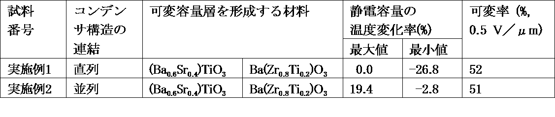
上記の結果から、可変容量素子において各可変容量層を形成する材料として別個の材料を用い、それぞれの材料の可変容量層で取得する容量値を調整することにより、一つの材料しか用いない比較例の可変容量素子とは全く異なる温度特性を得ることができることが示された。従って、可変容量層の材料および容量を調整することにより、温度特性および静電容量を調整することができ、用途に合わせた可変容量素子を設計することが可能になる。特に、コンデンサ構造を並列で連結した実施例2は、-30~+60℃の温度範囲で静電容量の変化率が±10%以下で、温度特性の変化が小さかった。また、実施例1および2の試料についても可変容量素子として機能するのが確認できた。
From the above results, a comparative example in which only one material is used by using a separate material as a material for forming each variable capacitance layer in the variable capacitance element, and adjusting a capacitance value acquired by the variable capacitance layer of each material. It was shown that temperature characteristics completely different from those of the variable capacitance element can be obtained. Therefore, by adjusting the material and capacitance of the variable capacitance layer, the temperature characteristics and capacitance can be adjusted, and a variable capacitance element can be designed according to the application. In particular, in Example 2 in which the capacitor structures were connected in parallel, the change rate of the capacitance was ± 10% or less in the temperature range of −30 to + 60 ° C., and the change in the temperature characteristics was small. Moreover, it was confirmed that the samples of Examples 1 and 2 also functioned as variable capacitance elements.
実施例3および4
可変容量層を形成する材料として、それぞれ、(Ba0.6Sr0.4)TiO3およびBa(Zr0.8Ti0.2)O3)を用い、厚みおよび対向部分の直径dを調整することにより、室温/20℃における、(Ba0.8Sr0.2)TiO3で形成されるコンデンサ構造の容量を約19pFとし、Ba(Zr0.8Ti0.2)O3で形成されるコンデンサ構造の容量を約56pFに調整して、実施例1および2と同様にして実施例3(直列)および実施例4(並列)の可変容量素子を作製した。 Examples 3 and 4
(Ba 0.6 Sr 0.4 ) TiO 3 and Ba (Zr 0.8 Ti 0.2 ) O 3 ) are used as materials for forming the variable capacitance layer, respectively, and the thickness and the diameter d of the opposing portion are adjusted. Thus, the capacitance of the capacitor structure formed of (Ba 0.8 Sr 0.2 ) TiO 3 at room temperature / 20 ° C. is set to about 19 pF, and the capacitor structure is formed of Ba (Zr 0.8 Ti 0.2 ) O 3 . The capacitance of the capacitor structure to be adjusted was adjusted to about 56 pF, and variable capacitance elements of Example 3 (series) and Example 4 (parallel) were fabricated in the same manner as in Examples 1 and 2.
実施例1および2と同様に、-40~+90℃の温度範囲での静電容量の温度特性を測定した。また、実施例1および2と同様に、容量可変率を測定した。結果を図11および表3に示す。
In the same manner as in Examples 1 and 2, the temperature characteristics of the capacitance in the temperature range of −40 to + 90 ° C. were measured. Further, the capacity variable rate was measured in the same manner as in Examples 1 and 2. The results are shown in FIG.

この実施例の場合、実施例1および2と異なり、直列で連結した実施例3において、-30~+60℃の温度範囲で静電容量の変化率が±15%以下となり、温度特性の変化が小さい可変容量素子を得ることができた。
In this example, unlike Examples 1 and 2, in Example 3 connected in series, the rate of change in capacitance was ± 15% or less in the temperature range of −30 to + 60 ° C., and the change in temperature characteristics was A small variable capacitor could be obtained.
以上の結果から、静電容量を取得する可変容量層を異なる材料で形成すること、それぞれの可変容量層で得られる静電容量値を適宜選択すること、および/または、複数のコンデンサ構造の配置を直列または並列から適宜選択することにより、単一の材料で形成した一つの可変容量層のみを有する可変容量場合よりも、静電容量の温度変化率を小さくすることができることが確認された。また、以上の結果から、可変容量素子の温度特性、静電容量値などは、可変容量層の材料、各コンデンサ構造の静電容量を調整することにより適宜設定することができるので、設計の自由度が高くなる。
From the above results, it is possible to form the variable capacitance layer for obtaining the capacitance from different materials, to appropriately select the capacitance value obtained from each variable capacitance layer, and / or to arrange the plurality of capacitor structures. It was confirmed that the temperature change rate of the capacitance can be made smaller by appropriately selecting from the series or the parallel as compared with the variable capacitance having only one variable capacitance layer formed of a single material. From the above results, the temperature characteristics and capacitance values of the variable capacitance elements can be set as appropriate by adjusting the capacitance layer material and the capacitance of each capacitor structure. The degree becomes higher.
本発明の保護素子は、RFID(Radio Frequency Identification)システムなど多種多様な電子機器に用いることができる。
The protection element of the present invention can be used for various electronic devices such as an RFID (Radio Frequency Identification) system.
1a…可変容量素子;1b…可変容量素子;2…可変容量層;
4…可変容量層;6…電極;8…電極;10…電極;12…絶縁部;
14…絶縁部;16…絶縁部;18…引き出し部;20…引き出し部;
22…外部電極;24…外部電極;26…ビアホール;
28…ビアホール;30…開口部;42…可変容量層;
44…可変容量層;46…電極;48…電極;50…電極;
52…電極;54…絶縁部;56…絶縁部;58…絶縁部;
60…引き出し部;62…引き出し部;64…引き出し部;
66…引き出し部;68…外部電極;70…外部電極;
72…ビアホール;74…ビアホール;76…ビアホール;
78…ビアホール;101…可変容量素子;102…絶縁部;
104…可変容量層;106…ビアホール;107…電極;
108…引き出し部;110…外部電極 DESCRIPTION OFSYMBOLS 1a ... Variable capacitance element; 1b ... Variable capacitance element; 2 ... Variable capacitance layer;
4 ... Variable capacitance layer; 6 ... Electrode; 8 ... Electrode; 10 ... Electrode; 12 ... Insulating part;
14 ... Insulating part; 16 ... Insulating part; 18 ... Drawer part; 20 ... Drawer part;
22 ... external electrode; 24 ... external electrode; 26 ... via hole;
28 ... via hole; 30 ... opening; 42 ... variable capacitance layer;
44 ... Variable capacitance layer; 46 ... Electrode; 48 ... Electrode; 50 ... Electrode;
52 ... Electrode; 54 ... Insulating part; 56 ... Insulating part; 58 ... Insulating part;
60 ... drawer part; 62 ... drawer part; 64 ... drawer part;
66 ... Extraction part; 68 ... External electrode; 70 ... External electrode;
72 ... via hole; 74 ... via hole; 76 ... via hole;
78: Via hole; 101 ... Variable capacitance element; 102 ... Insulating part;
104 ... variable capacitance layer; 106 ... via hole; 107 ... electrode;
108 ... Lead-out part; 110 ... External electrode
4…可変容量層;6…電極;8…電極;10…電極;12…絶縁部;
14…絶縁部;16…絶縁部;18…引き出し部;20…引き出し部;
22…外部電極;24…外部電極;26…ビアホール;
28…ビアホール;30…開口部;42…可変容量層;
44…可変容量層;46…電極;48…電極;50…電極;
52…電極;54…絶縁部;56…絶縁部;58…絶縁部;
60…引き出し部;62…引き出し部;64…引き出し部;
66…引き出し部;68…外部電極;70…外部電極;
72…ビアホール;74…ビアホール;76…ビアホール;
78…ビアホール;101…可変容量素子;102…絶縁部;
104…可変容量層;106…ビアホール;107…電極;
108…引き出し部;110…外部電極 DESCRIPTION OF
4 ... Variable capacitance layer; 6 ... Electrode; 8 ... Electrode; 10 ... Electrode; 12 ... Insulating part;
14 ... Insulating part; 16 ... Insulating part; 18 ... Drawer part; 20 ... Drawer part;
22 ... external electrode; 24 ... external electrode; 26 ... via hole;
28 ... via hole; 30 ... opening; 42 ... variable capacitance layer;
44 ... Variable capacitance layer; 46 ... Electrode; 48 ... Electrode; 50 ... Electrode;
52 ... Electrode; 54 ... Insulating part; 56 ... Insulating part; 58 ... Insulating part;
60 ... drawer part; 62 ... drawer part; 64 ... drawer part;
66 ... Extraction part; 68 ... External electrode; 70 ... External electrode;
72 ... via hole; 74 ... via hole; 76 ... via hole;
78: Via hole; 101 ... Variable capacitance element; 102 ... Insulating part;
104 ... variable capacitance layer; 106 ... via hole; 107 ... electrode;
108 ... Lead-out part; 110 ... External electrode
Claims (8)
- 誘電体材料から構成される複数の可変容量層と、
可変容量層の両主表面上に可変容量層を介して対向して位置する複数の対の電極と、
複数の絶縁部と、
少なくとも1対の引き出し部と、
を有してなり、
上記複数の可変容量層および上記複数の絶縁部は、交互に積層され、積層体を形成し、
上記複数の可変容量層と上記複数の対の電極は、複数のコンデンサ構造を構成し、
上記引き出し部は、その一端において上記コンデンサ構造を構成する電極に電気的に接続され、絶縁部を貫通して、他端において外部電極または他の電気要素と電気的に接続されること
を特徴とする、可変容量素子。 A plurality of variable capacitance layers made of a dielectric material;
A plurality of pairs of electrodes positioned opposite to each other on both main surfaces of the variable capacitance layer via the variable capacitance layer;
A plurality of insulation parts;
At least one pair of drawers;
Having
The plurality of variable capacitance layers and the plurality of insulating portions are alternately stacked to form a stacked body,
The plurality of variable capacitance layers and the plurality of pairs of electrodes constitute a plurality of capacitor structures,
The lead portion is electrically connected to an electrode constituting the capacitor structure at one end, penetrates the insulating portion, and is electrically connected to an external electrode or another electric element at the other end. A variable capacitance element. - 複数のコンデンサ構造が、電気的に並列に配置されていることを特徴とする、請求項1に記載の可変容量素子。 2. The variable capacitance element according to claim 1, wherein a plurality of capacitor structures are electrically arranged in parallel.
- 複数のコンデンサ構造が、電気的に直列に配置されていることを特徴とする、請求項1に記載の可変容量素子。 2. The variable capacitance element according to claim 1, wherein a plurality of capacitor structures are electrically arranged in series.
- 複数のコンデンサ構造の内少なくとも1つのコンデンサ構造が、他のコンデンサ構造と異なる静電容量を有することを特徴とする、請求項1~3のいずれかに記載の可変容量素子。 The variable capacitance element according to any one of claims 1 to 3, wherein at least one of the plurality of capacitor structures has a capacitance different from that of the other capacitor structures.
- 複数の可変容量層が、異なる誘電体材料から形成される少なくとも2種の可変容量層を含むことを特徴とする、請求項1~4のいずれかに記載の可変容量素子。 5. The variable capacitance element according to claim 1, wherein the plurality of variable capacitance layers include at least two types of variable capacitance layers formed of different dielectric materials.
- 可変容量層が、(i)BaおよびSrの少なくとも1種、および、(ii)TiおよびZrの少なくとも1種を含むことを特徴とする、請求項1~5のいずれかに記載の可変容量素子。 6. The variable capacitance element according to claim 1, wherein the variable capacitance layer includes (i) at least one of Ba and Sr, and (ii) at least one of Ti and Zr. .
- 対の引き出し部が、可変容量層に略垂直な同軸上にあることを特徴とする請求項1~6のいずれかに記載の可変容量素子。 The variable capacitance element according to any one of claims 1 to 6, wherein the pair of lead portions are on the same axis substantially perpendicular to the variable capacitance layer.
- 電極および引き出し部が、AgまたはCuから構成されていることを特徴とする請求項1~7のいずれかに記載の可変容量素子。 The variable capacitance element according to any one of claims 1 to 7, wherein the electrode and the lead portion are made of Ag or Cu.
Priority Applications (3)
| Application Number | Priority Date | Filing Date | Title |
|---|---|---|---|
| JP2017502403A JP6439856B2 (en) | 2015-02-27 | 2016-02-24 | Variable capacitance element |
| CN201680011049.4A CN107251178B (en) | 2015-02-27 | 2016-02-24 | Variable-capacitance element |
| US15/686,276 US10262805B2 (en) | 2015-02-27 | 2017-08-25 | Variable capacitance element |
Applications Claiming Priority (2)
| Application Number | Priority Date | Filing Date | Title |
|---|---|---|---|
| JP2015039341 | 2015-02-27 | ||
| JP2015-039341 | 2015-02-27 |
Related Child Applications (1)
| Application Number | Title | Priority Date | Filing Date |
|---|---|---|---|
| US15/686,276 Continuation US10262805B2 (en) | 2015-02-27 | 2017-08-25 | Variable capacitance element |
Publications (1)
| Publication Number | Publication Date |
|---|---|
| WO2016136771A1 true WO2016136771A1 (en) | 2016-09-01 |
Family
ID=56788623
Family Applications (1)
| Application Number | Title | Priority Date | Filing Date |
|---|---|---|---|
| PCT/JP2016/055338 WO2016136771A1 (en) | 2015-02-27 | 2016-02-24 | Variable capacitance element |
Country Status (4)
| Country | Link |
|---|---|
| US (1) | US10262805B2 (en) |
| JP (1) | JP6439856B2 (en) |
| CN (1) | CN107251178B (en) |
| WO (1) | WO2016136771A1 (en) |
Families Citing this family (1)
| Publication number | Priority date | Publication date | Assignee | Title |
|---|---|---|---|---|
| CN109360702A (en) * | 2018-11-30 | 2019-02-19 | 铜陵市三盛电子有限公司 | One kind easily adjusting more capacitance value capacitors |
Citations (4)
| Publication number | Priority date | Publication date | Assignee | Title |
|---|---|---|---|---|
| JPH10223475A (en) * | 1997-01-31 | 1998-08-21 | Mitsubishi Materials Corp | Method for regulating capacitor capacitance |
| JP2006245367A (en) * | 2005-03-04 | 2006-09-14 | Matsushita Electric Ind Co Ltd | Varistor and its production process |
| JP2013536989A (en) * | 2010-09-03 | 2013-09-26 | エプコス アーゲー | Ceramic device and manufacturing method thereof |
| WO2013183472A1 (en) * | 2012-06-08 | 2013-12-12 | 株式会社村田製作所 | Variable capacitance element, high-frequency device, and communication device |
Family Cites Families (7)
| Publication number | Priority date | Publication date | Assignee | Title |
|---|---|---|---|---|
| DE102005050638B4 (en) * | 2005-10-20 | 2020-07-16 | Tdk Electronics Ag | Electrical component |
| JP2010258402A (en) * | 2008-09-26 | 2010-11-11 | Sony Corp | Capacitance element and resonance circuit |
| JP5666123B2 (en) * | 2009-12-03 | 2015-02-12 | デクセリアルズ株式会社 | Variable capacity device |
| CN103703528A (en) * | 2011-08-10 | 2014-04-02 | 富士通株式会社 | Electronic device having variable capacitance element and method for manufacturing same |
| GB2511233B (en) | 2011-10-26 | 2015-06-24 | Murata Manufacturing Co | Variable capacitance element for wireless communication systems |
| US9253822B2 (en) * | 2013-06-25 | 2016-02-02 | International Business Machines Corporation | Phase change material variable capacitor |
| WO2015030170A1 (en) * | 2013-09-02 | 2015-03-05 | 株式会社村田製作所 | Variable capacitance element |
-
2016
- 2016-02-24 CN CN201680011049.4A patent/CN107251178B/en active Active
- 2016-02-24 JP JP2017502403A patent/JP6439856B2/en active Active
- 2016-02-24 WO PCT/JP2016/055338 patent/WO2016136771A1/en active Application Filing
-
2017
- 2017-08-25 US US15/686,276 patent/US10262805B2/en active Active
Patent Citations (4)
| Publication number | Priority date | Publication date | Assignee | Title |
|---|---|---|---|---|
| JPH10223475A (en) * | 1997-01-31 | 1998-08-21 | Mitsubishi Materials Corp | Method for regulating capacitor capacitance |
| JP2006245367A (en) * | 2005-03-04 | 2006-09-14 | Matsushita Electric Ind Co Ltd | Varistor and its production process |
| JP2013536989A (en) * | 2010-09-03 | 2013-09-26 | エプコス アーゲー | Ceramic device and manufacturing method thereof |
| WO2013183472A1 (en) * | 2012-06-08 | 2013-12-12 | 株式会社村田製作所 | Variable capacitance element, high-frequency device, and communication device |
Also Published As
| Publication number | Publication date |
|---|---|
| US20170352490A1 (en) | 2017-12-07 |
| JP6439856B2 (en) | 2018-12-19 |
| US10262805B2 (en) | 2019-04-16 |
| CN107251178A (en) | 2017-10-13 |
| JPWO2016136771A1 (en) | 2017-11-24 |
| CN107251178B (en) | 2019-03-22 |
Similar Documents
| Publication | Publication Date | Title |
|---|---|---|
| CN102810398B (en) | Laminated ceramic electronic component and multilayer ceramic capacitor | |
| CN102810397A (en) | Multilayer ceramic electronic component and multilayer ceramic capacitor | |
| KR102029468B1 (en) | Multi-layered ceramic electronic parts and method of manufacturing the same | |
| JP2022116273A (en) | Multilayer ceramic capacitor and method for manufacturing the same | |
| JP2021010000A (en) | Multilayer ceramic capacitor and manufacturing method thereof | |
| JP4637674B2 (en) | Multilayer capacitor | |
| WO2012070376A1 (en) | Multilayer ceramic electronic component and method for manufacturing same | |
| JP5811174B2 (en) | Electronic component and manufacturing method thereof | |
| KR101882998B1 (en) | Laminated ceramic electronic parts | |
| US9202625B2 (en) | Laminated ceramic electronic component and method of fabricating the same | |
| JP2021103767A (en) | Multilayer ceramic capacitor and method of manufacturing the same | |
| JP2013030775A (en) | Multi-layered ceramic electronic component | |
| CN104335305B (en) | Laminated ceramic capacitor | |
| JP4095961B2 (en) | Electrical multilayer element | |
| JP6439856B2 (en) | Variable capacitance element | |
| US10128051B2 (en) | Variable capacitance component | |
| JP2009266716A (en) | Conductive paste, and manufacturing method of laminated ceramic capacitor | |
| KR102057040B1 (en) | Multilayer ceramic capacitor and method for manufacturing multilayer ceramic capacitor | |
| WO2016136772A1 (en) | Variable capacitance element | |
| JPH0817675A (en) | Chip type laminated ceramic capacitor | |
| JP2014187217A (en) | Laminated capacitor | |
| KR100739491B1 (en) | Igh dielectric capacitor and fabricating method thereof | |
| KR101892863B1 (en) | Laminated ceramic electronic parts | |
| KR20210001970A (en) | Multilayer Electronic Component | |
| JP2014183187A (en) | Laminated ceramic capacitor |
Legal Events
| Date | Code | Title | Description |
|---|---|---|---|
| 121 | Ep: the epo has been informed by wipo that ep was designated in this application |
Ref document number: 16755515 Country of ref document: EP Kind code of ref document: A1 |
|
| ENP | Entry into the national phase |
Ref document number: 2017502403 Country of ref document: JP Kind code of ref document: A |
|
| NENP | Non-entry into the national phase |
Ref country code: DE |
|
| 122 | Ep: pct application non-entry in european phase |
Ref document number: 16755515 Country of ref document: EP Kind code of ref document: A1 |