WO2016136750A1 - ボールねじナットおよびその製造方法 - Google Patents
ボールねじナットおよびその製造方法 Download PDFInfo
- Publication number
- WO2016136750A1 WO2016136750A1 PCT/JP2016/055276 JP2016055276W WO2016136750A1 WO 2016136750 A1 WO2016136750 A1 WO 2016136750A1 JP 2016055276 W JP2016055276 W JP 2016055276W WO 2016136750 A1 WO2016136750 A1 WO 2016136750A1
- Authority
- WO
- WIPO (PCT)
- Prior art keywords
- ball screw
- screw nut
- coil material
- sleeve
- wire
- Prior art date
- Legal status (The legal status is an assumption and is not a legal conclusion. Google has not performed a legal analysis and makes no representation as to the accuracy of the status listed.)
- Ceased
Links
Images



Classifications
-
- B—PERFORMING OPERATIONS; TRANSPORTING
- B21—MECHANICAL METAL-WORKING WITHOUT ESSENTIALLY REMOVING MATERIAL; PUNCHING METAL
- B21D—WORKING OR PROCESSING OF SHEET METAL OR METAL TUBES, RODS OR PROFILES WITHOUT ESSENTIALLY REMOVING MATERIAL; PUNCHING METAL
- B21D51/00—Making hollow objects
- B21D51/16—Making hollow objects characterised by the use of the objects
- B21D51/18—Making hollow objects characterised by the use of the objects vessels, e.g. tubs, vats, tanks, sinks, or the like
-
- B—PERFORMING OPERATIONS; TRANSPORTING
- B21—MECHANICAL METAL-WORKING WITHOUT ESSENTIALLY REMOVING MATERIAL; PUNCHING METAL
- B21F—WORKING OR PROCESSING OF METAL WIRE
- B21F3/00—Coiling wire into particular forms
- B21F3/02—Coiling wire into particular forms helically
-
- B—PERFORMING OPERATIONS; TRANSPORTING
- B21—MECHANICAL METAL-WORKING WITHOUT ESSENTIALLY REMOVING MATERIAL; PUNCHING METAL
- B21H—MAKING PARTICULAR METAL OBJECTS BY ROLLING, e.g. SCREWS, WHEELS, RINGS, BARRELS, BALLS
- B21H3/00—Making helical bodies or bodies having parts of helical shape
- B21H3/08—Making helical bodies or bodies having parts of helical shape internal screw-threads
-
- F—MECHANICAL ENGINEERING; LIGHTING; HEATING; WEAPONS; BLASTING
- F16—ENGINEERING ELEMENTS AND UNITS; GENERAL MEASURES FOR PRODUCING AND MAINTAINING EFFECTIVE FUNCTIONING OF MACHINES OR INSTALLATIONS; THERMAL INSULATION IN GENERAL
- F16H—GEARING
- F16H25/00—Gearings comprising primarily only cams, cam-followers and screw-and-nut mechanisms
- F16H25/18—Gearings comprising primarily only cams, cam-followers and screw-and-nut mechanisms for conveying or interconverting oscillating or reciprocating motions
- F16H25/20—Screw mechanisms
- F16H25/22—Screw mechanisms with balls, rollers, or similar members between the co-operating parts; Elements essential to the use of such members
-
- F—MECHANICAL ENGINEERING; LIGHTING; HEATING; WEAPONS; BLASTING
- F16—ENGINEERING ELEMENTS AND UNITS; GENERAL MEASURES FOR PRODUCING AND MAINTAINING EFFECTIVE FUNCTIONING OF MACHINES OR INSTALLATIONS; THERMAL INSULATION IN GENERAL
- F16H—GEARING
- F16H25/00—Gearings comprising primarily only cams, cam-followers and screw-and-nut mechanisms
- F16H25/18—Gearings comprising primarily only cams, cam-followers and screw-and-nut mechanisms for conveying or interconverting oscillating or reciprocating motions
- F16H25/20—Screw mechanisms
- F16H25/24—Elements essential to such mechanisms, e.g. screws, nuts
Definitions
- the present invention relates to a ball screw nut formed in a spiral ball rolling groove used for an electric power steering device, an electric actuator and the like of an automobile, and a method of manufacturing the ball screw nut.
- the ball screw is composed of a ball screw shaft having a spiral ball rolling groove formed on the outer periphery, a ball screw nut having a spiral ball rolling groove formed in a cylindrical surface, and corresponding both ball rolling grooves. It is a mechanical element that is composed of a large number of balls that are rotatably accommodated in a configured ball rolling path, and that converts the rotation of the ball screw shaft or the ball screw nut into a translational motion in the axial direction.
- this ball screw nut generally has a ball rolling groove formed on the inner periphery by cutting and grinding. That is, a pilot hole is drilled in the material using a drill, and a spiral ball rolling groove is cut on the peripheral surface of the pilot hole with a cutting tool. Next, after heat treatment such as carburizing and quenching is performed, the outer diameter portion is ground with a cylindrical grinder or the like, and finally the surface of the ball rolling groove cut with a grindstone is ground.
- the ball screw nut 50 has a substantially cylindrical shape, and has a flange 50a at one end thereof for coupling to a conveying machine or the like.
- a ball rolling groove 50c on which a ball (not shown) rolls is formed on the inner peripheral surface of the ball screw nut 50, and a flat surface portion 50b is formed on the outer peripheral surface.
- a member such as a return pipe that connects one end and the other end of the ball rolling groove 50c is coupled to the flat surface portion 50b.
- the ball rolling groove 50c is formed into a gothic arc groove or the like that combines two arcs having a radius of curvature slightly larger than the radius of the ball by rolling.
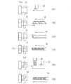
- the ball screw nut 50 is manufactured by a process as shown in FIG. First, the outer periphery of the cylindrical material 51 is cut using a cutting tool 52, a flange 51a is formed on the material 51 (S1), and a pilot hole 51b is formed on the material 51 using a drill 53 (S2). Next, using the boring tool 54, the lower hole 51b is spread to a normal size (S3), and then the raw material 51 is rotated at a low speed of 100 to 200 rpm, and the rolling tap 55 is inserted into the lower hole 51b. The ball rolling groove 51c is rolled on the inner peripheral surface of 51 (S4). In this way, the surface of the ball rolling groove 51c is burnished.
- the end mill 56 is used to groove the return portion 51 d for circulating the ball through the material 51. Then, using the cutting tool 52, the outer periphery of the material 51 is cut to finish the outer peripheral surface (S5). Finally, the rolling tap 55 is again passed through the ball rolling groove 51c of the material 51, and the ball rolling groove 51c is deburred.
- the ball rolling groove 51c is formed on the inner peripheral surface of the material 51 in the rolling process (S4), a grinding process for grinding the ball rolling groove using a conventional grindstone is not necessary, Even with a small-diameter ball screw nut, the ball rolling groove 51c can be easily processed. For this reason, since the processing cost of the ball rolling groove 51c can be reduced and the number of processing steps can be reduced, the lead time can be shortened (see, for example, Patent Document 1).
- the ball screw device 57 includes a ball screw nut 58, a ball screw shaft 59, and a large number of ball rolling elements 60.
- the ball screw nut 58 is a coil spring in which a wire rod having a cross-sectional shape suitable for the inner hole to become the ball rolling groove 58a is wound in a coil shape with close contact, and the ball rolling race 61 is formed into a cylindrical shape.
- Ball rolling grooves 58a are formed in the inner holes of the ball rolling races 61 along the joining portions of the wires.
- the cross-sectional shape of these ball rolling grooves 58a is a shape in which two circular arcs are continuous. There is no.
- a substantially cylindrical outer holding member 62 made of synthetic resin is integrally formed outside the ball rolling race 61, and a return passage 63 parallel to the central axis is formed on the outer periphery of the outer holding member 62. Further, end caps 64 are fixed to both end faces, and guide grooves 65 that communicate the ball rolling grooves 58 a and the return passages 63 are formed in the end caps 64. Thereby, a ball screw can be obtained in large quantities and inexpensively with a simple structure (for example, refer patent document 2).
- JP 2000-88072 A Japanese Patent Laid-Open No. 9-4690
- a wire having a cross-sectional shape suitable for forming the ball rolling groove 58a is brought into close contact with each other and wound in a coil shape, and is substantially made of a synthetic resin on the outside of the ball rolling race 61. Since the cylindrical outer holding member 62 is integrally formed by injection molding, there is a limit in ensuring accuracy such as the concentricity of the ball rolling groove 58a, and the ball rolling groove 58a is affected by the thermal effect during injection molding. There was a risk that the surface hardness of the steel would decrease.
- the present invention has been made in view of such circumstances.
- the wire is coiled in a spiral shape, and a concave groove between the wire and the wire is rolled to form a thread groove (ball rolling groove).
- the invention described in claim 1 of the present invention is a ball screw nut in which a spiral thread groove on which a large number of balls roll on an inner peripheral surface is formed.
- the coil material is formed by winding a wire, and the spiral thread groove is formed on the inner periphery, and a sleeve that accommodates the coil material, and the sleeve is formed in a cylindrical shape from a thin steel plate, Extending radially inward at both ends and integrally provided with hooks for fixing the coil material so as not to move in the axial direction, the thread groove is formed between adjacent wire members of the coil material, and the surface of the thread groove is rolled. Constructed from surface construction.
- the ball screw nut in which a spiral thread groove in which a large number of balls roll on the inner peripheral surface is formed, the ball screw nut is formed by winding a wire, and the spiral thread groove on the inner periphery It is composed of a coil material formed with a sleeve that accommodates this coil material, and this sleeve is formed in a cylindrical shape from a thin steel plate, extends radially inward at both ends, and fixes the coil material so that it cannot move in the axial direction.
- a thread groove is formed between adjacent wires of the coil material, and the surface of the thread groove is formed by a rolling surface, so that the processing stress in the rolling process of the nut can be suppressed.
- Ball screw nuts that can form high-precision screw grooves such as concentricity and groove shape, and can eliminate rough machining and grinding of expensive screw grooves, thus reducing costs. Can provide That.
- the coil material is formed of a hard steel wire
- a desired surface hardness can be easily obtained by heat treatment.
- the sleeve is formed of case-hardened steel or medium-high carbon steel, a desired surface hardness can be easily obtained by heat treatment.
- the method invention according to claim 4 of the present invention is a ball screw nut manufacturing method in which a spiral screw groove on which a large number of balls roll on an inner peripheral surface is formed.
- a coil material is formed by coiling molding in which a wire is spirally wound, and a sleeve in which the coil material is fitted is formed by pressing a thin steel plate into a cylindrical portion and one end portion of the cylindrical portion in a radial direction.
- a step of forming an inwardly extending flange, and the other end portion of the sleeve is in contact with the flange in a state where the wire material of the coil material is in close contact, and the coil material is restrained from moving in the axial direction.
- a step of forming a ridge by edge bending a fixed die is inserted into the inner diameter of the coil material, and an outer diameter surface of the sleeve is constrained by a roll die, and the roll die and the fixed die With the nut held in the radial direction, the fixed die is pressed against the concave groove formed between the wire rods of the coil material, the roll die is moved in the radial direction and pressurized, and the thread groove is rolled. And a step in which the nut is subjected to heat treatment and hardened.
- the ball screw nut in which a spiral screw groove on which a large number of balls roll is formed on the inner peripheral surface, the ball screw nut is coiled by coiling molding in which a wire is wound spirally.
- a step in which a sleeve into which the coil material is fitted is formed by pressing a thin steel plate into a cylindrical portion and a flange extending radially inward at one end of the cylindrical portion, and the coil material The other end of the sleeve is fixed to the inner diameter of the coil material while the other end of the sleeve is bent by edge bending while the coil material is in close contact with the collar and the movement of the coil material is restricted in the axial direction.
- the outer diameter surface of the sleeve is constrained by the roll die, and the nut is fixed between the roll die and the fixing die in the radial direction, and fixed to the concave groove formed between the wire members of the coil material.
- the fixed die can be pressed into the groove to be formed and rolled to reduce the processing force of the fixed die, and the fixed die can be miniaturized and can be used with a small-diameter nut, Since the processing stress in the rolling process of the nut can be suppressed, highly accurate thread grooves such as concentricity and groove shape can be formed. Further, it is possible to omit the rough machining and grinding of the high-cost screw groove, and it is possible to provide a ball screw nut that achieves cost reduction.
- the sleeve is formed into a cup shape by pressing from a thin steel plate, the inner peripheral surface is ironed, and the bottom is punched to form the one flange. If formed, the inner peripheral surface can be smoothed, and the accuracy can be improved at low cost.
- the processing force during rolling is reduced. Further reduction can be achieved, and the accuracy of the thread groove can be further improved.
- the ball screw nut according to the present invention is a ball screw nut in which a spiral screw groove on which a large number of balls roll is formed on an inner peripheral surface, wherein the ball screw nut is formed by winding a wire, A coil material in which the spiral thread groove is formed, and a sleeve that accommodates the coil material.
- the sleeve is formed in a cylindrical shape from a thin steel plate and extends radially inward at both ends.
- the screw groove is formed between the adjacent wire rods of the coil material, and the surface of the screw groove is formed of a rolling surface,
- the processing stress in the rolling process can be reduced, high-precision screw grooves such as concentricity and groove shape can be formed, and high-cost rough and grinding of screw grooves can be omitted. Reduce costs It is possible to provide a ball screw nut that Tsu.
- the ball screw nut manufacturing method is a ball screw nut manufacturing method in which a spiral screw groove on which a large number of balls roll on an inner peripheral surface is formed.
- a step of forming a coil material by coiling forming that is spirally wound, and a sleeve in which the coil material is fitted are formed by pressing a thin steel plate into a cylindrical portion and one end portion of the cylindrical portion inward in the radial direction. And the other end of the sleeve is edge bent in a state in which the coil material is in a state of being restrained from moving in the axial direction.
- a step of forming a flange by processing a fixed die is inserted into the inner diameter of the coil material, and an outer diameter surface of the sleeve is constrained by a roll die, and the roll die and the fixed die With the nut clamped in the radial direction, the fixed die is pressed against the concave groove formed between the wire rods of the coil material, the roll die is moved in the radial direction and pressurized, and the thread groove is rolled. And the step of heat-treating the nut and hardening it so that the fixed die is pressed by pressing the fixed die into the concave groove formed between the adjacent wires, and the fixed die is processed.
- the force can be reduced, the fixed die can be downsized, and even small diameter nuts can be handled, and the processing stress in the rolling process of the nut can be reduced, so concentricity and groove shape For example, a highly accurate thread groove can be formed. Further, it is possible to omit the rough machining and grinding of the high-cost screw groove, and it is possible to provide a ball screw nut that achieves cost reduction.
- FIG. 1 It is a longitudinal section showing one embodiment of a ball screw concerning the present invention.
- the manufacturing process of the ball screw nut which concerns on this invention is shown, (a) is explanatory drawing which shows a coiling shaping
- the manufacturing process of the ball screw nut which concerns on this invention is shown, (a) is explanatory drawing which shows the crimping process of a sleeve, (b) is explanatory drawing which shows the process of rolling the coil material of (a). is there.
- It is a principal part enlarged view which shows the thread groove part of the ball screw nut which concerns on this invention.
- a ball screw nut in which a spiral thread groove on which a large number of balls roll on an inner peripheral surface is formed.
- the ball screw nut is formed by winding a hard steel wire, and the spiral thread groove is formed on an inner periphery. Is formed from a thin steel plate made of case-hardened steel by pressing, and extends radially inward at both ends.
- a gutter for fixing the coil material so as not to move in the axial direction is integrally provided, and the thread groove is formed by rolling between adjacent wire materials of the coil material.
- FIG. 1 is a longitudinal sectional view showing an embodiment of a ball screw according to the present invention
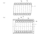
- FIG. 2 shows a manufacturing process of a ball screw nut according to the present invention
- (a) is an explanatory view showing a coiling molding process
- (B) is explanatory drawing which shows the process of inserting the coil material of (a) into a sleeve
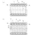
- FIG. 3 shows the manufacturing process of the ball screw nut which concerns on this invention
- (a) shows the crimping process of a sleeve.
- FIG. 4B is an explanatory view showing a process of rolling the coil material of FIG. 4A
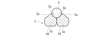
- FIG. 4 is an enlarged view of a main part showing a thread groove portion of a ball screw nut according to the present invention
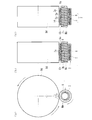
- FIG. The manufacturing process of the ball screw nut which concerns on this invention is shown
- (a) is explanatory drawing which shows the pre-process of the rolling process of a nut
- (c) is the post process of the nut of (b). It is explanatory drawing shown.
- the ball screw 1 includes a nut 2 having a spiral thread groove 2a formed on an inner peripheral surface thereof, and a spiral thread groove 3a inserted in the nut 2 and corresponding to the screw groove 2a of the nut 2 on the outer peripheral surface. , A plurality of balls 4 accommodated in a rolling path formed by the opposing screw grooves 2a and 3a, and a circulation member (not shown) for these balls 4. Yes.
- each thread groove 2a, 3a may be a circular arc shape or a Gothic arc shape, but here, it has a Gothic arc shape that allows a large contact angle with the ball 4 and a small axial clearance. Is formed. Thereby, the rigidity with respect to an axial load becomes high and generation
- the nut 2 includes a coil material 5 having a spiral thread groove 2a formed on the inner periphery and a sleeve 6 that accommodates the coil material 5.
- the coil material 5 is made of, for example, a chromium molybdenum steel wire (JIS standard SCM435 system) or a hard steel wire (JIS standard SW-C system), and is formed by coiling in a spiral shape.
- the material of the coil material 5 is not limited to the exemplified chromium molybdenum steel wire or hard steel wire, but may be a stainless steel wire such as SUS-WR.
- the sleeve 6 is formed into a cylindrical shape by press working (drawing) from a thin steel plate made of case-hardened steel such as SCM415 or SCM420, and is integrally provided with flanges 6a and 6b that fix the coil material 5 so that it cannot move in the axial direction at both ends. ing.
- the material of the sleeve 6 can be exemplified by medium and high carbon steel such as S55C and tool steel such as SK5.
- FIG. 2 shows a manufacturing process of the nut 2 in the embodiment of the present invention.
- a coil material 7 having a predetermined number of turns is formed by coiling molding in which a wire 7a having a circular cross section is wound spirally.
- the coil material 7 is fitted into a sleeve 8 formed into a cylindrical shape by pressing from a thin steel plate.
- the sleeve 8 includes a cylindrical portion 8a and a flange 8b that extends radially inward at one end of the cylindrical portion 8a. Note that the inner diameter of the cylindrical portion 8 a is slightly smaller than the outer diameter of the coil material 7 in the free state.
- the sleeve 8 is formed into a cup shape by press working from a thin steel plate, subjected to ironing processing for smoothing the inner peripheral surface and trimming processing for trimming the end portion, and punching the bottom portion of the cup-shaped sleeve.
- a ridge 6a is formed.
- the other end portion of the sleeve 8 is brought into contact with the flange 6a in a state in which the wire 7a of the coil material 7 is in close contact, and the coil material 7 is restrained from moving in the axial direction.
- the flange 6b is formed by edge bending.
- a fixed die (mandrel) serving as a rolling jig is inserted into the inner diameter of the coil material 7 described later, and the outer diameter surface of the sleeve 6 is restrained by a roll die.
- the fixed die With the nut 2 held between the roll die and the fixed die in the radial direction, the fixed die is pressed against the concave groove 9 formed between the wire rods 7a, 7a, the roll die is moved in the radial direction and pressurized, and the thread groove 2a is rolled.
- a circulation member for example, a piece window of the piece member is formed in the nut 2 and heat treatment such as carburizing and quenching is performed, and a hardening treatment is performed so that the surface hardness is in a range of 42 to 50 HRC. Is done.
- the outer diameter surface of the wire 5a becomes a flat surface 10 corresponding to the inner diameter surface of the sleeve 6 as shown in FIG. 4, and the adhesion and stability to the sleeve 6 are further increased.
- the inner diameter surface has a desired Gothic arc shape corresponding to the shape of the fixed die, that is, a thread groove 2a having two curvature centers having a radius of curvature set slightly larger than the radius of the ball 4. It is formed.
- the rolling process of the nut 2 thread groove 2a will be described with reference to FIG.
- the fixed die Mn is inserted, and the outer diameter surface of the sleeve 6 is constrained by the roll die Rd, and the nut is formed by the roll die Rd and the fixed die Mn. 2 is held in the radial direction.
- the fixed die Mn is pressed against the concave groove 9 formed between the wires 7a and 7a, and the roll die Rd is rotated in a certain direction (indicated by an arrow in the figure).
- the roll die Rd rotates, the sleeve 6 and the coil material 7 are integrally rotated in the opposite direction (indicated by arrows in the figure).
- the roll die Rd is moved in the radial direction and pressed (indicated by a white arrow in the figure), and the thread groove 2a is rolled into the concave groove 9 between the wire rods 7a and 7a.
- the spiral ridge 7b is formed on the outer periphery of the fixed die Mn, and the outer peripheral surface of the ridge 7b is formed in a cross-sectional gothic arc shape corresponding to the thread groove 2a.
- the fixed die Mn is pressed into the concave groove 9 formed between the adjacent wire rods 7a and 7a and is rolled to form the thread groove 2a, thereby reducing the processing force of the fixed die Mn.
- the fixing die Mn can be reduced in size and can be handled with a small-diameter nut, and the processing stress in the rolling process of the nut 2 can be suppressed, so that the concentricity, groove shape, etc.
- a highly accurate thread groove 2a can be formed. Furthermore, it is possible to omit the rough machining and grinding of the high-cost thread groove, and it is possible to provide the ball screw nut 2 that achieves cost reduction.
- the lead angle can be easily set by changing the inclination angle for winding the wire 5a of the coil material 5, and the pitch of the thread groove 2a can be changed by changing the cross-sectional shape / dimension of the wire 5a. It can be easily set, and a desired preload can be applied to the ball screw.
- pitch refers to the distance between the groove bottoms of the screw grooves.
- the shape of the wire 7a of the coil material 7 can be further reduced by reducing the working force during rolling by forming the shape of the wire 7a before winding into a rough shape close to the finished shape by drawing.
- the accuracy of the thread groove 2a can be further improved.
- the ball screw nut according to the present invention can be applied to a ball screw used for an automatic manual transmission, an electric brake, an electric power steering, and an engine valve system control actuator, which are used particularly for vehicles such as automobiles.
Landscapes
- Engineering & Computer Science (AREA)
- Mechanical Engineering (AREA)
- General Engineering & Computer Science (AREA)
- Transmission Devices (AREA)
Abstract
ロールダイスを小型化して小径であっても加工力を減少させて高精度に成形できると共に、低コスト化を図ったボールねじナットおよびその製造方法を提供する。 内周面に多数のボール4が転動する螺旋状のねじ溝2aが形成されたボールねじナット2において、ボールねじナット2が、硬鋼線材を巻回して形成され、内周に螺旋状のねじ溝2aが形成されたコイル材5と、このコイル材5を収容するスリーブ6とで構成され、スリーブ6が肌焼き鋼からなる薄肉鋼板からプレス加工によって円筒状に形成され、両端に径方向内方に延び、コイル材5を軸方向移動不可に固定する鍔6a、6bを一体に備えると共に、コイル材5の隣り合う線材間に転造加工によってねじ溝2aが形成されているので、ナット2の転造加工における加工力を抑えることができ、高精度な溝形状のねじ溝2aを成形することができる。
Description
本発明は、自動車の電動パワーステアリング装置や電動アクチュエータ等に用いられ、多数のボールが転動する螺旋状のボール転走溝が形成されたボールねじナットおよびその製造方法に関するものである。
ボールねじは、外周に螺旋状のボール転走溝が形成されたボールねじ軸と、円筒面内に螺旋状のボール転走溝が形成されたボールねじナットと、対応する両ボール転走溝で構成されたボール転動路内に転動自在に収容された多数のボールとからなり、ボールねじ軸あるいはボールねじナットの回転を軸方向の並進運動に変換する機械要素である。
従来、このボールねじナットは、切削と研削とによって内周にボール転走溝が形成されているのが一般的である。すなわち、ドリルを用いて素材に下孔が開けられ、バイトでこの下穴の周面に螺旋状のボール転走溝が切削加工される。次に、浸炭焼入れ等の熱処理が行われた後、円筒研削盤等で外径部の研削加工が行われ、最後に砥石を用いて切削されたボール転走溝の表面が研削加工される。
然しながら、従来の切削加工と研削加工とによってボール転走溝が形成されたボールねじナットにおいては、内径の小さいボールねじナットを研削加工する場合、砥石を下孔に挿入することができず、研削加工ができないことがあった。また、内径が小さいボールねじナットでなくても大リードのものについては、リード角が大きいため、下孔への砥石の挿入量が制限を受けて、やはり研削加工ができないことがあった。当然、研削加工は、ナットの芯出し等の調整に時間と工数がかかりコスト的に不利である。
こうした問題点を解決したものとして、図6に示すようなボールねじナットが知られている。このボールねじナット50は、略円筒状をなし、その一端には搬送用機械等に結合するためのフランジ50aを有している。ボールねじナット50の内周面には、ボール(図示せず)が転動するボール転走溝50cが形成され、外周面には、平面部50bが形成されている。この平面部50bには、ボール転走溝50cの一端と他端を連結するリターンパイプ等の部材が結合される。ボール転走溝50cは、転造によりボールの半径よりも僅かに大きい曲率半径の2つの円弧を組み合わせたゴシックアーク溝等に形成されている。
また、このボールねじナット50は、図7に示すような工程で製造される。まず、円筒状の素材51の外周を、バイト52を用いて切削加工し、素材51にフランジ51aを形成し(S1)、ドリル53を用いて素材51に下孔51bを形成する(S2)。次に、中ぐりバイト54を用いて、下孔51bを正規の寸法にくり広げた(S3)後に、素材51を100~200rpmで低速回転させ、転造タップ55を下穴51bに挿入し、素材51の内周面にボール転走溝51cを転造する(S4)。こうしてボール転走溝51cの表面はバニシ仕上げされる。次に、エンドミル56を用いて、素材51にボールを循環させるためのリターン部51dを溝加工する。そして、バイト52を用いて、素材51の外周を切削加工し、外周面を仕上げる(S5)。最後に、素材51のボール転走溝51cに再び転造タップ55を通し、ボール転走溝51cのバリを取る。
このように、転造工程(S4)で素材51の内周面にボール転走溝51cを形成するので、従来のような砥石を用いてボール転走溝を研削する研削工程が必要なくなり、また、小径のボールねじナットであっても容易にボール転走溝51cを加工することができる。このため、ボール転走溝51cの加工コストを低減することができ、加工工数を少なくすることができるので、リードタイムを短くすることができる(例えば、特許文献1参照。)。
然しながら、こうした従来のボールねじナット50では、ボール転走溝51cの転造が塑性加工であるため加工力が大きくなる。そのため、ロールダイスが大径になり、ボールねじナット50の内径が小径ではナット内に入らない場合があり、ねじ軸の転造加工に比べ、ナットの転造は一般的ではなかった。
一方、図8に示すようなボールねじ装置57が知られている。このボールねじ装置57は、ボールねじナット58、ボールねじ軸59および多数のボール転動体60からなる。ボールねじナット58は、内孔がボール転走溝58aとなるのに適した断面形状の線材を、密着させてコイル状に巻回したコイルスプリングで、円筒状に成形されたボール転走レース61がある。このボール転走レース61の内孔には各線材の接合部分に沿ったボール転走溝58aが形成されており、これらボール転走溝58aの断面形状は、円弧を2個連続させた形状をなしている。
ボール転走レース61の外側には合成樹脂製で略円筒状の外側保持部材62が一体形成され、この外側保持部材62の外周部には中心軸線と平行な戻し通路63が形成されている。また、両端面にエンドキャップ64が固定され、このエンドキャップ64には、ボール転走溝58aと戻し通路63とを連通する案内溝65が形成されている。これにより、簡単な構成でボールねじを大量かつ安価に得ることができる(例えば、特許文献2参照。)。
然しながら、こうした従来のボールねじナット58では、予めボール転走溝58aとなるのに適した断面形状の線材を密着させてコイル状に巻回し、ボール転走レース61の外側に合成樹脂製で略円筒状の外側保持部材62を射出成形によって一体形成するため、ボール転走溝58aの同芯度等の精度を確保するには限界があると共に、射出成形時の熱影響によってボール転走溝58aの表面硬度が低下する恐れがあった。
本発明は、このような事情に鑑みてなされたもので、線材を螺旋状にコイリング成形し、線材と線材の間の凹溝を転造加工してねじ溝(ボール転走溝)に成形することに着目し、ロールダイスを小型化して小径であっても加工力を減少させて高精度に成形できると共に、低コスト化を図ったボールねじナットおよびその製造方法を提供することを目的とする。
係る目的を達成すべく、本発明のうち請求項1に記載の発明は、内周面に多数のボールが転動する螺旋状のねじ溝が形成されたボールねじナットにおいて、前記ボールねじナットが、線材を巻回して形成され、内周に螺旋状の前記ねじ溝が形成されたコイル材と、このコイル材を収容するスリーブとで構成され、このスリーブが薄肉鋼板から円筒状に形成され、両端に径方向内方に延び、前記コイル材を軸方向移動不可に固定する鍔を一体に備えると共に、前記コイル材の隣り合う線材間に前記ねじ溝が形成され、このねじ溝の表面が転造面で構成されている。
このように、内周面に多数のボールが転動する螺旋状のねじ溝が形成されたボールねじナットにおいて、ボールねじナットが、線材を巻回して形成され、内周に螺旋状のねじ溝が形成されたコイル材と、このコイル材を収容するスリーブとで構成され、このスリーブが薄肉鋼板から円筒状に形成され、両端に径方向内方に延び、コイル材を軸方向移動不可に固定する鍔を一体に備えると共に、コイル材の隣り合う線材間にねじ溝が形成され、このねじ溝の表面が転造面で構成されているので、ナットの転造加工における加工応力を抑えることができ、同芯度や溝形状等、高精度なねじ溝を成形することができると共に、高コストなねじ溝の粗加工や研削加工を省略することができ、低コスト化を図ったボールねじナットを提供することができる。
好ましくは、請求項2に記載の発明のように、前記コイル材が硬鋼線材で形成されていれば、熱処理によって容易に所望の表面硬度を得ることができる。
また、請求項3に記載の発明のように、前記スリーブが肌焼き鋼または中高炭素鋼で形成されていれば、熱処理によって容易に所望の表面硬度を得ることができる。
また、本発明のうち請求項4に記載の方法発明は、内周面に多数のボールが転動する螺旋状のねじ溝が形成されたボールねじナットの製造方法において、前記ボールねじナットが、線材を螺旋状に巻回するコイリング成形によりコイル材が形成される工程と、前記コイル材が内嵌されるスリーブが、薄肉鋼板からプレス加工によって円筒部と、この円筒部の一端部に径方向内方に延びる鍔が形成される工程と、前記コイル材の線材が密着した状態で前記鍔に当接され、前記コイル材が軸方向に移動が拘束された状態で前記スリーブの他端部が縁曲げ加工によって鍔が形成される工程と、前記コイル材の内径に固定ダイスが挿入されると共に、前記スリーブの外径面がロールダイスによって拘束され、このロールダイスと前記固定ダイスとで前記ナットを径方向に挟持した状態で、前記コイル材の線材間に形成される凹溝に前記固定ダイスを押し付け、前記ロールダイスを径方向に移動させて加圧し、前記ねじ溝が転造加工される工程と、前記ナットに熱処理が施されて硬化処理される工程を備えている。
このように、内周面に多数のボールが転動する螺旋状のねじ溝が形成されたボールねじナットの製造方法において、ボールねじナットが、線材を螺旋状に巻回するコイリング成形によりコイル材が形成される工程と、コイル材が内嵌されるスリーブが、薄肉鋼板からプレス加工によって円筒部と、この円筒部の一端部に径方向内方に延びる鍔が形成される工程と、コイル材の線材が密着した状態で鍔に当接され、コイル材が軸方向に移動が拘束された状態でスリーブの他端部が縁曲げ加工によって鍔が形成される工程と、コイル材の内径に固定ダイスが挿入されると共に、スリーブの外径面がロールダイスによって拘束され、このロールダイスと固定ダイスとでナットを径方向に挟持した状態で、コイル材の線材間に形成される凹溝に固定ダイスを押し付け、ロールダイスを径方向に移動させて加圧し、ねじ溝が転造加工される工程と、ナットに熱処理が施されて硬化処理される工程を備えているので、隣り合う線材間に形成される凹溝に固定ダイスを押圧し、転造加工して固定ダイスの加工力を減少させることができ、固定ダイスを小型化することができて小径のナットでも対応することができると共に、ナットの転造加工における加工応力を抑えることができるので、同芯度や溝形状等、高精度なねじ溝を成形することができる。さらに、高コストなねじ溝の粗加工や研削加工を省略することができ、低コスト化を図ったボールねじのナットを提供することができる。
好ましくは、請求項5に記載の発明のように、前記スリーブが薄肉鋼板からプレス加工によってカップ状に形成され、内周面がしごき加工されると共に、底部が打ち抜き加工されて前記一方の鍔が形成されていれば、内周面を平滑にすることができると共に、低コストで精度を向上させることができる。
また、請求項6に記載の発明のように、前記コイル材の巻回する前の線材の形状が仕上げ形状に近い粗形状に予め引抜き加工によって成形されていれば、転造時の加工力をさらに減少させることができ、一層、ねじ溝の精度を向上させることができる。
また、請求項7に記載の発明のように、前記線材の断面形状・寸法を変更することによって前記ねじ溝のピッチが設定されていれば、ボールねじに所望の予圧を適宜付与することができる。
本発明に係るボールねじナットは、内周面に多数のボールが転動する螺旋状のねじ溝が形成されたボールねじナットにおいて、前記ボールねじナットが、線材を巻回して形成され、内周に螺旋状の前記ねじ溝が形成されたコイル材と、このコイル材を収容するスリーブとで構成され、このスリーブが薄肉鋼板から円筒状に形成され、両端に径方向内方に延び、前記コイル材を軸方向移動不可に固定する鍔を一体に備えると共に、前記コイル材の隣り合う線材間に前記ねじ溝が形成され、このねじ溝の表面が転造面で構成されているので、ナットの転造加工における加工応力を抑えることができ、同芯度や溝形状等、高精度なねじ溝を成形することができると共に、高コストなねじ溝の粗加工や研削加工を省略することができ、低コスト化を図ったボールねじナットを提供することができる。
また、本発明に係るボールねじナットの製造方法は、内周面に多数のボールが転動する螺旋状のねじ溝が形成されたボールねじナットの製造方法において、前記ボールねじナットが、線材を螺旋状に巻回するコイリング成形によりコイル材が形成される工程と、前記コイル材が内嵌されるスリーブが、薄肉鋼板からプレス加工によって円筒部と、この円筒部の一端部に径方向内方に延びる鍔が形成される工程と、前記コイル材の線材が密着した状態で前記鍔に当接され、前記コイル材が軸方向に移動が拘束された状態で前記スリーブの他端部が縁曲げ加工によって鍔が形成される工程と、前記コイル材の内径に固定ダイスが挿入されると共に、前記スリーブの外径面がロールダイスによって拘束され、このロールダイスと前記固定ダイスとで前記ナットを径方向に挟持した状態で、前記コイル材の線材間に形成される凹溝に前記固定ダイスを押し付け、前記ロールダイスを径方向に移動させて加圧し、前記ねじ溝が転造加工される工程と、前記ナットに熱処理が施されて硬化処理される工程を備えているので、隣り合う線材間に形成される凹溝に固定ダイスを押圧して転造加工して固定ダイスの加工力を減少させることができ、固定ダイスを小型化することができて小径のナットでも対応することができると共に、ナットの転造加工における加工応力を抑えることができるので、同芯度や溝形状等、高精度なねじ溝を成形することができる。さらに、高コストなねじ溝の粗加工や研削加工を省略することができ、低コスト化を図ったボールねじのナットを提供することができる。
内周面に多数のボールが転動する螺旋状のねじ溝が形成されたボールねじナットにおいて、前記ボールねじナットが、硬鋼線材を巻回して形成され、内周に螺旋状の前記ねじ溝が形成されたコイル材と、このコイル材を収容するスリーブとで構成され、このスリーブが肌焼き鋼からなる薄肉鋼板からプレス加工によって円筒状に形成され、両端に径方向内方に延び、前記コイル材を軸方向移動不可に固定する鍔を一体に備えると共に、前記コイル材の隣り合う線材間に転造加工によって前記ねじ溝が形成されている。
以下、本発明の実施の形態を図面に基づいて詳細に説明する。
図1は、本発明に係るボールねじの一実施形態を示す縦断面図、図2は、本発明に係るボールねじナットの製造工程を示し、(a)は、コイリング成形工程を示す説明図、(b)は、(a)のコイル材をスリーブに挿入する工程を示す説明図、図3は、本発明に係るボールねじナットの製造工程を示し、(a)は、スリーブの加締工程を示す説明図、(b)は、(a)のコイル材を転造加工する工程を示す説明図、図4は、本発明に係るボールねじナットのねじ溝部を示す要部拡大図、図5は、本発明に係るボールねじナットの製造工程を示し、(a)、(b)は、ナットの転造加工の前工程を示す説明図、(c)は、(b)のナットの後工程を示す説明図である。
図1は、本発明に係るボールねじの一実施形態を示す縦断面図、図2は、本発明に係るボールねじナットの製造工程を示し、(a)は、コイリング成形工程を示す説明図、(b)は、(a)のコイル材をスリーブに挿入する工程を示す説明図、図3は、本発明に係るボールねじナットの製造工程を示し、(a)は、スリーブの加締工程を示す説明図、(b)は、(a)のコイル材を転造加工する工程を示す説明図、図4は、本発明に係るボールねじナットのねじ溝部を示す要部拡大図、図5は、本発明に係るボールねじナットの製造工程を示し、(a)、(b)は、ナットの転造加工の前工程を示す説明図、(c)は、(b)のナットの後工程を示す説明図である。
このボールねじ1は、内周面に螺旋状のねじ溝2aが形成されたナット2と、このナット2に内挿され、外周面にナット2のねじ溝2aに対応する螺旋状のねじ溝3aが形成されたねじ軸3と、これら対向するねじ溝2a、3aにより形成された転動路に収容された多数のボール4と、これらボール4の循環用部材(図示せず)とを備えている。
各ねじ溝2a、3aの断面形状は、サーキュラアーク形状であってもゴシックアーク形状であっても良いが、ここではボール4との接触角が大きくとれ、アキシアルすきまが小さく設定できるゴシックアーク形状に形成されている。これにより、軸方向荷重に対する剛性が高くなり、かつ振動の発生を抑制することができる。
ナット2は、内周に螺旋状のねじ溝2aが形成されたコイル材5と、このコイル材5を収容するスリーブ6とで構成されている。コイル材5は、例えば、クロムモリブデン鋼線材(JIS規格のSCM435系)あるいは硬鋼線材(JIS規格のSW-C系)等からなり、螺旋状にコイリング成形により形成されている。なお、コイル材5の材質は、例示したクロムモリブデン鋼線材や硬鋼線材に限らず、SUS-WR等のステンレス鋼線材等であっても良い。
スリーブ6は、SCM415やSCM420等の肌焼き鋼の薄肉鋼板からプレス加工(絞り加工)によって円筒状に形成され、両端にコイル材5を軸方向移動不可に固定する鍔6a、6bを一体に備えている。なお、スリーブ6の材質は、これ以外にも、例えば、S55C等の中高炭素鋼やSK5等の工具鋼を例示することができる。
図2に、本発明の実施形態におけるナット2の製造工程を示す。最初に、(a)に示すように、断面が円形の線材7aを螺旋状に巻回するコイリング成形により所定の巻き数からなるコイル材7が形成される。次に、(b)に示すように、薄肉鋼板からプレス加工によって円筒状に形成されたスリーブ8にコイル材7が内嵌される。スリーブ8は、円筒部8aと、この円筒部8aの一端部に径方向内方に延びる鍔8bを備えている。なお、円筒部8aの内径は、コイル材7の自由状態での外径よりも僅かに小径に形成されている。
スリーブ8は、薄肉鋼板からプレス加工によってカップ状に形成され、内周面を平滑にするためのしごき加工、および端部を切り揃えるトリミング加工が施され、カップ状のスリーブの底部を打ち抜き加工によって鍔6aが形成されている。
その後、図3(a)に示すように、コイル材7の線材7aが密着した状態で鍔6aに当接され、コイル材7が軸方向に移動が拘束された状態でスリーブ8の他端部が縁曲げ加工によって鍔6bが形成される。次に、(b)に示すように、後述するコイル材7の内径に転造治具となる固定ダイス(マンドレル)が挿入されると共に、スリーブ6の外径面がロールダイスによって拘束され、このロールダイスと固定ダイスとでナット2を径方向に挟持した状態で、線材7a、7a間に形成される凹溝9に固定ダイスを押し付け、ロールダイスを径方向に移動させて加圧し、ねじ溝2aが転造加工される。
次に、循環用部材となる、例えば、駒部材の駒窓がナット2に形成されると共に、浸炭焼入れ等の熱処理が施され、所定の表面硬さ42~50HRCの範囲になるように硬化処理される。
前述した転造加工によって、図4に示すように、線材5aの外径面はスリーブ6の内径面に対応して平坦面10となり、スリーブ6に対する密着度と安定度が一段と高まる。一方、内径面は、固定ダイスの形状に対応して所望のゴシックアーク形状、すなわち、ボール4の半径よりも僅かに大きく設定された曲率半径を有する2つの曲率中心からなる形状のねじ溝2aに形成される。
次に、図5を用いて、ナット2ねじ溝2aの転造加工について説明する。まず、図5(a)、(b)に示すように、固定ダイスMnが挿入されると共に、スリーブ6の外径面がロールダイスRdによって拘束され、このロールダイスRdと固定ダイスMnとでナット2を径方向に挟持する。そして、線材7a、7a間に形成される凹溝9に固定ダイスMnを押し付け、ロールダイスRdを一定方向(図中矢印にて示す)に回転させる。この時、(a)に示すように、ロールダイスRdの回転に伴い、スリーブ6とコイル材7が一体に逆方向に回転(図中矢印にて示す)する。その後、(c)に示すように、ロールダイスRdを径方向に移動させて加圧(図中白矢印にて示す)し、線材7a、7a間の凹溝9にねじ溝2aが転造加工される。ここで、固定ダイスMnの外周には螺旋状の凸条7bが形成され、この凸条7bの外周面がねじ溝2aに相当する断面ゴシックアーク形状に形成されている。
本実施形態では、隣り合う線材7a、7a間に形成される凹溝9に固定ダイスMnを押圧して転造加工されてねじ溝2aが形成されているため、固定ダイスMnの加工力を減少させることができ、固定ダイスMnを小型化することができて小径のナットでも対応することができると共に、ナット2の転造加工における加工応力を抑えることができるので、同芯度や溝形状等、高精度なねじ溝2aを成形することができる。さらに、高コストなねじ溝の粗加工や研削加工を省略することができ、低コスト化を図ったボールねじのナット2を提供することができる。
ここで、コイル材5の線材5aを巻回する傾斜角を変更することによって容易にリード角を設定することができると共に、線材5aの断面形状・寸法を変更することによってねじ溝2aのピッチを容易に設定することができ、ボールねじに所望の予圧を付与することもできる。ここで「ピッチ」とは、ねじ溝の溝底間の距離のことをいう。
また、コイル材7の線材7aの形状を、巻回する前の線材7aの形状を仕上げ形状に近い粗形状に予め引抜き加工によって成形することにより、転造時の加工力をさらに減少させることができ、一層、ねじ溝2aの精度を向上させることができる。
以上、本発明の実施の形態について説明を行ったが、本発明はこうした実施の形態に何等限定されるものではなく、あくまで例示であって、本発明の要旨を逸脱しない範囲内において、さらに種々なる形態で実施し得ることは勿論のことであり、本発明の範囲は、特許請求の範囲の記載によって示され、さらに特許請求の範囲に記載の均等の意味、および範囲内のすべての変更を含む。
本発明に係るボールねじナットは、特に自動車等の車両に用いられる自動マニュアルトランスミッション、電動ブレーキ、電動パワーステアリング、エンジン動弁系制御アクチュエータに使用されるボールねじに適用することができる。
1 ボールねじ
2 ナット
2a、3a ねじ溝
3 ねじ軸
4 ボール
5、7 コイル材
5a、7a 線材
6、8 スリーブ
6a、6b 鍔
7b 凸条
8a 円筒部
9 凹溝
10 平坦面
50 ボールねじナット
50a、51a フランジ
50b 平面部
50c、51c ボール転走溝
51 素材
51b 下穴
51d リターン部
52 バイト
53 ドリル
54 中ぐりバイト
55 転造タップ
56 エンドミル
57 ボールねじ装置
58 ボールねじナット
58a ボール転走溝
59 ボールねじ軸
60 ボール転動体
61 ボール転走レース
62 外側保持部材
63 戻し通路
64 エンドキャップ
65 案内溝
Mn 固定ダイス
Rd ロールダイス
2 ナット
2a、3a ねじ溝
3 ねじ軸
4 ボール
5、7 コイル材
5a、7a 線材
6、8 スリーブ
6a、6b 鍔
7b 凸条
8a 円筒部
9 凹溝
10 平坦面
50 ボールねじナット
50a、51a フランジ
50b 平面部
50c、51c ボール転走溝
51 素材
51b 下穴
51d リターン部
52 バイト
53 ドリル
54 中ぐりバイト
55 転造タップ
56 エンドミル
57 ボールねじ装置
58 ボールねじナット
58a ボール転走溝
59 ボールねじ軸
60 ボール転動体
61 ボール転走レース
62 外側保持部材
63 戻し通路
64 エンドキャップ
65 案内溝
Mn 固定ダイス
Rd ロールダイス
Claims (7)
- 内周面に多数のボールが転動する螺旋状のねじ溝が形成されたボールねじナットにおいて、
前記ボールねじナットが、線材を巻回して形成され、内周に螺旋状の前記ねじ溝が形成されたコイル材と、
このコイル材を収容するスリーブとで構成され、
このスリーブが薄肉鋼板から円筒状に形成され、両端に径方向内方に延び、前記コイル材を軸方向移動不可に固定する鍔を一体に備えると共に、
前記コイル材の隣り合う線材間に前記ねじ溝が形成され、このねじ溝の表面が転造面で構成されていることを特徴とするボールねじナット。 - 前記コイル材が硬鋼線材で形成されている請求項1に記載のボールねじナット。
- 前記スリーブが肌焼き鋼または中高炭素鋼で形成されている請求項1に記載のボールねじナット。
- 内周面に多数のボールが転動する螺旋状のねじ溝が形成されたボールねじナットの製造方法において、
前記ボールねじナットが、線材を螺旋状に巻回するコイリング成形によりコイル材が形成される工程と、
前記コイル材が内嵌されるスリーブが、薄肉鋼板からプレス加工によって円筒部と、この円筒部の一端部に径方向内方に延びる鍔が形成される工程と、
前記コイル材の線材が密着した状態で前記鍔に当接され、前記コイル材が軸方向に移動が拘束された状態で前記スリーブの他端部が縁曲げ加工によって鍔が形成される工程と、
前記コイル材の内径に固定ダイスが挿入されると共に、前記スリーブの外径面がロールダイスによって拘束され、このロールダイスと前記固定ダイスとで前記ナットを径方向に挟持した状態で、前記コイル材の線材間に形成される凹溝に前記固定ダイスを押し付け、前記ロールダイスを径方向に移動させて加圧し、前記ねじ溝が転造加工される工程と、
前記ナットに熱処理が施されて硬化処理される工程を備えていることを特徴とするボールねじナットの製造方法。 - 前記スリーブが薄肉鋼板からプレス加工によってカップ状に形成され、内周面がしごき加工されると共に、底部が打ち抜き加工されて前記一方の鍔が形成されている請求項4に記載のボールねじナットの製造方法。
- 前記コイル材の巻回する前の線材の形状が仕上げ形状に近い粗形状に予め引抜き加工によって成形されている請求項4に記載のボールねじナットの製造方法。
- 前記線材の断面形状・寸法を変更することによって前記ねじ溝のピッチが設定されている請求項4に記載のボールねじナットの製造方法。
Applications Claiming Priority (4)
| Application Number | Priority Date | Filing Date | Title |
|---|---|---|---|
| JP2015-034446 | 2015-02-24 | ||
| JP2015034446 | 2015-02-24 | ||
| JP2016-010494 | 2016-01-22 | ||
| JP2016010494A JP2016156499A (ja) | 2015-02-24 | 2016-01-22 | ボールねじナットおよびその製造方法 |
Publications (1)
| Publication Number | Publication Date |
|---|---|
| WO2016136750A1 true WO2016136750A1 (ja) | 2016-09-01 |
Family
ID=56788411
Family Applications (1)
| Application Number | Title | Priority Date | Filing Date |
|---|---|---|---|
| PCT/JP2016/055276 Ceased WO2016136750A1 (ja) | 2015-02-24 | 2016-02-23 | ボールねじナットおよびその製造方法 |
Country Status (1)
| Country | Link |
|---|---|
| WO (1) | WO2016136750A1 (ja) |
Cited By (4)
| Publication number | Priority date | Publication date | Assignee | Title |
|---|---|---|---|---|
| CN107553141A (zh) * | 2017-09-05 | 2018-01-09 | 四川鸿舰重型机械制造有限责任公司 | 全自动多规格挤压滚圆磨球生产线 |
| CN112313430A (zh) * | 2018-04-24 | 2021-02-02 | 日本精工株式会社 | 滚珠丝杠 |
| CN112728030A (zh) * | 2019-10-28 | 2021-04-30 | 株式会社捷太格特 | 滚珠丝杠螺母、转动单元及制造滚珠丝杠螺母的方法 |
| CN113441911A (zh) * | 2021-06-23 | 2021-09-28 | 陕西万方汽车零部件有限公司 | 一种内循环转向螺母一体加工方法 |
Citations (2)
| Publication number | Priority date | Publication date | Assignee | Title |
|---|---|---|---|---|
| JP2000088072A (ja) * | 1998-09-11 | 2000-03-28 | Thk Co Ltd | ボールねじナット、該ボールねじナットを使用した直線案内装置及びステアリング用ボールねじ並びにボールねじナットの製造方法 |
| JP2002021968A (ja) * | 2000-07-05 | 2002-01-23 | Kazuo Chikajima | ボールナット及びボールネジ装置 |
-
2016
- 2016-02-23 WO PCT/JP2016/055276 patent/WO2016136750A1/ja not_active Ceased
Patent Citations (2)
| Publication number | Priority date | Publication date | Assignee | Title |
|---|---|---|---|---|
| JP2000088072A (ja) * | 1998-09-11 | 2000-03-28 | Thk Co Ltd | ボールねじナット、該ボールねじナットを使用した直線案内装置及びステアリング用ボールねじ並びにボールねじナットの製造方法 |
| JP2002021968A (ja) * | 2000-07-05 | 2002-01-23 | Kazuo Chikajima | ボールナット及びボールネジ装置 |
Cited By (5)
| Publication number | Priority date | Publication date | Assignee | Title |
|---|---|---|---|---|
| CN107553141A (zh) * | 2017-09-05 | 2018-01-09 | 四川鸿舰重型机械制造有限责任公司 | 全自动多规格挤压滚圆磨球生产线 |
| CN112313430A (zh) * | 2018-04-24 | 2021-02-02 | 日本精工株式会社 | 滚珠丝杠 |
| CN112313430B (zh) * | 2018-04-24 | 2024-04-05 | 日本精工株式会社 | 滚珠丝杠 |
| CN112728030A (zh) * | 2019-10-28 | 2021-04-30 | 株式会社捷太格特 | 滚珠丝杠螺母、转动单元及制造滚珠丝杠螺母的方法 |
| CN113441911A (zh) * | 2021-06-23 | 2021-09-28 | 陕西万方汽车零部件有限公司 | 一种内循环转向螺母一体加工方法 |
Similar Documents
| Publication | Publication Date | Title |
|---|---|---|
| US10641370B2 (en) | Ball screw | |
| WO2016136750A1 (ja) | ボールねじナットおよびその製造方法 | |
| US11326674B2 (en) | Spindle nut, threaded drive, and method for manufacturing a spindle nut | |
| JP2013099840A (ja) | ねじ軸及びその製造方法並びにボールねじユニット | |
| CN101500823A (zh) | 轴承单元滚道环部件、轴承单元以及用于制造轴承单元滚道环部件的方法和设备 | |
| US8436501B2 (en) | Rotor, manufacturing method thereof and electric gear motor having the rotor | |
| WO2015137494A1 (ja) | ボールねじおよびその製造方法 | |
| KR20200069291A (ko) | 랙 바아 블랭크 재료, 랙 바아, 랙 바아 블랭크 재료 제조 방법, 및 랙 바아 제조 방법 | |
| JP2005083549A (ja) | ボールねじナットおよびその製造方法 | |
| US10464151B2 (en) | Raceway groove machining method, bearing, ball screw device, machine and vehicle production method | |
| JP2015024471A (ja) | ボールねじ用ナットの加工工具及び加工方法 | |
| CN114127443B (zh) | 用于制造螺纹驱动器的螺纹螺母、特别是滚珠丝杠驱动器的滚珠丝杠螺母的方法 | |
| JP7179991B2 (ja) | 被加工物上のボール軌道、および、そのようにして製造されたボール軌道を有するボールねじナットの製造方法 | |
| JP2016156499A (ja) | ボールねじナットおよびその製造方法 | |
| JP5202975B2 (ja) | 等速自在継手用内側継手部材、その製造方法、及び等速自在継手 | |
| JP4888760B2 (ja) | ねじ軸形成方法及びボールねじ機構のねじ軸 | |
| JP2013166173A (ja) | ボールねじの製造方法 | |
| JP5322451B2 (ja) | 等速ジョイント、等速ジョイント外輪の製造方法およびその製造装置 | |
| JP2008215422A (ja) | アクチュエータ用ボールねじおよびそのねじ溝加工方法 | |
| JP2009185930A (ja) | 等速ジョイントおよび等速ジョイント外輪の製造方法 | |
| JP2006181638A (ja) | ラジアル玉軸受用軌道輪及びその製造方法 | |
| JP5322449B2 (ja) | 等速ジョイントおよび等速ジョイント外輪の製造方法 | |
| JP2016017544A (ja) | 駒式ボールねじ | |
| JP2006346684A (ja) | インフィード転造ダイス及びボールねじ機構のねじ軸 | |
| JP5853560B2 (ja) | ボールねじの製造方法 |
Legal Events
| Date | Code | Title | Description |
|---|---|---|---|
| 121 | Ep: the epo has been informed by wipo that ep was designated in this application |
Ref document number: 16755494 Country of ref document: EP Kind code of ref document: A1 |
|
| NENP | Non-entry into the national phase |
Ref country code: DE |
|
| 122 | Ep: pct application non-entry in european phase |
Ref document number: 16755494 Country of ref document: EP Kind code of ref document: A1 |