WO2016136643A1 - 流路開閉弁 - Google Patents
流路開閉弁 Download PDFInfo
- Publication number
- WO2016136643A1 WO2016136643A1 PCT/JP2016/054977 JP2016054977W WO2016136643A1 WO 2016136643 A1 WO2016136643 A1 WO 2016136643A1 JP 2016054977 W JP2016054977 W JP 2016054977W WO 2016136643 A1 WO2016136643 A1 WO 2016136643A1
- Authority
- WO
- WIPO (PCT)
- Prior art keywords
- flow path
- valve body
- seal ring
- valve
- closing valve
- Prior art date
- Legal status (The legal status is an assumption and is not a legal conclusion. Google has not performed a legal analysis and makes no representation as to the accuracy of the status listed.)
- Ceased
Links
Images









Classifications
-
- F—MECHANICAL ENGINEERING; LIGHTING; HEATING; WEAPONS; BLASTING
- F16—ENGINEERING ELEMENTS AND UNITS; GENERAL MEASURES FOR PRODUCING AND MAINTAINING EFFECTIVE FUNCTIONING OF MACHINES OR INSTALLATIONS; THERMAL INSULATION IN GENERAL
- F16K—VALVES; TAPS; COCKS; ACTUATING-FLOATS; DEVICES FOR VENTING OR AERATING
- F16K5/00—Plug valves; Taps or cocks comprising only cut-off apparatus having at least one of the sealing faces shaped as a more or less complete surface of a solid of revolution, the opening and closing movement being predominantly rotary
- F16K5/06—Plug valves; Taps or cocks comprising only cut-off apparatus having at least one of the sealing faces shaped as a more or less complete surface of a solid of revolution, the opening and closing movement being predominantly rotary with plugs having spherical surfaces; Packings therefor
-
- F—MECHANICAL ENGINEERING; LIGHTING; HEATING; WEAPONS; BLASTING
- F16—ENGINEERING ELEMENTS AND UNITS; GENERAL MEASURES FOR PRODUCING AND MAINTAINING EFFECTIVE FUNCTIONING OF MACHINES OR INSTALLATIONS; THERMAL INSULATION IN GENERAL
- F16K—VALVES; TAPS; COCKS; ACTUATING-FLOATS; DEVICES FOR VENTING OR AERATING
- F16K35/00—Means to prevent accidental or unauthorised actuation
Definitions
- the present invention relates to a flow path opening / closing valve, and more particularly to a flow path opening / closing valve provided with a lock mechanism.
- a ball valve may be used as the flow path opening / closing valve.
- the valve body of the ball valve is seated on the seal ring when the ball valve is closed.
- a relatively large load torque is generated because the seal ring rubs against the ball valve body.
- Patent Document 1 describes a flow path opening / closing valve.
- the center of curvature of the valve body of the ball valve is disposed at a position off the axis of the shaft that rotates the valve body of the ball valve.
- movement of a ball valve is reduced by the said arrangement
- An object of the present invention is to provide a flow path opening / closing valve capable of reducing the load torque during the opening / closing operation of the flow path opening / closing valve and locking the flow path opening / closing valve.
- the flow path opening / closing valve includes a valve housing having a flow path, a valve body that is disposed in the flow path and is rotatable with the shaft, a first drive mechanism that rotates the shaft, and the flow path.
- a lock mechanism for preventing rotation of the valve body includes a first engagement portion provided in the seal ring or the seal ring moving mechanism, and a second engagement portion provided in the valve body.
- a flow path opening / closing valve capable of reducing the load torque during the opening / closing operation of the flow path opening / closing valve and locking the flow path opening / closing valve.
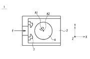
- FIG. 1A is a schematic cross-sectional view schematically showing a flow path opening / closing valve, and shows a closed state of the flow path opening / closing valve.
- FIG. 1B is a schematic cross-sectional view schematically showing the flow path opening / closing valve, and is a view showing an open state of the flow path opening / closing valve.
- FIG. 2 is a schematic cross-sectional view schematically showing the flow path opening / closing valve.
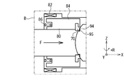
- FIG. 3A is an enlarged view of a region B surrounded by a two-dot chain line in FIG.
- FIG. 3B is an enlarged view of a region B surrounded by a two-dot chain line in FIG. 2 and shows a state where the lock by the lock mechanism 90 is released.
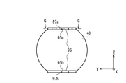
- 3C is a CC arrow view of the valve body shown in FIG. 3B.
- 3D is a CC arrow view of the valve body (modified example) shown in FIG. 3B.
- 3E is a cross-sectional view taken along the line GG in FIG. 3D.
- FIG. 4 is a schematic cross-sectional view showing a modification of the lock mechanism.
- FIG. 5 is a schematic cross-sectional view schematically showing the flow path opening / closing valve.
- FIG. 6A is a schematic perspective view (partially cutaway perspective view) schematically showing a flow path opening / closing valve.
- FIG. 6B is a schematic perspective view (partially cutaway perspective view) schematically showing the flow path opening / closing valve.
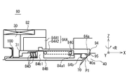
- FIG. 7A is an enlarged view of a region D surrounded by a two-dot chain line in FIG. 5, and shows a state in which the seal ring is in contact with the valve body and the valve body is locked by the lock mechanism.
- FIG. 7B is an enlarged view of a region D surrounded by a two-dot chain line in FIG. 5, and shows a state where the seal ring is in contact with the valve body and the valve body is unlocked.
- FIG. 7A is an enlarged view of a region D surrounded by a two-dot chain line in FIG. 5, and shows a state where the seal ring is in contact with the valve body and the valve body is unlocked.
- FIG. 7C is an enlarged view of a region D surrounded by a two-dot chain line in FIG. 5 and shows a state in which the seal ring is separated from the valve body and the valve body is unlocked.
- FIG. 7D is an enlarged view of a region D surrounded by a two-dot chain line in FIG. 5, and shows a state where the seal ring is in contact with the valve body and the valve body is locked by the lock mechanism.
- FIG. 8A is a schematic plan view illustrating an example of a first engagement portion and a second engagement portion.
- FIG. 8B is a schematic side view showing an example of the first engagement portion.
- FIG. 8C is a schematic plan view illustrating an example of the first engagement portion and the second engagement portion.
- FIG. 8D is a schematic plan view illustrating an example of the first engagement portion and the second engagement portion.
- the axis parallel to the fluid flow at the inlet portion of the flow path opening / closing valve is the X axis
- the direction parallel to the axis of the shaft that rotates the valve body of the flow path opening / closing valve is the Z axis, X axis, and Z axis.
- the axis orthogonal to is defined as the Y axis.
- FIG. 1A is a schematic cross-sectional view schematically showing the flow path opening / closing valve 1, and shows a closed state of the flow path opening / closing valve 1.
- FIG. 1B is a schematic cross-sectional view schematically showing the flow path opening / closing valve 1, and is a view showing an open state of the flow path opening / closing valve 1.
- the flow path opening / closing valve 1 includes a valve housing 3, a valve body 4 (ball valve body), and a seal ring 7.
- the valve housing 3 has a flow path 2.
- the valve body 4 is disposed in the flow path 2 and is rotatable around the rotation axis A1.
- the seal ring 7 is disposed in the flow path 2.
- an arrow F indicates the flow direction of the fluid at the inlet portion of the flow path opening / closing valve 1. The direction indicated by the arrow F coincides with the positive direction of the X axis.
- the 1A has a spherically shaped portion 4a that is seated on the seal ring 7 when the flow path opening / closing valve 1 is closed.
- the center of curvature A2 of the spherical shape portion 4a is not on the rotation axis A1. In other words, the center of curvature A2 of the spherical shape portion 4a is at a position eccentric from the rotation axis A1.
- the center of curvature A2 of the spherical shape portion 4a is not on the rotation axis A1.
- the valve body 4 rotates around the rotation axis A ⁇ b> 1 (in other words, when the flow path opening / closing valve 1 opens)
- the valve body 4 is separated from the seal ring 7.
- the valve body 4 can be rotated with a smaller torque. In other words, by separating the valve body 4 from the seal ring 7, it is possible to reduce the load torque during the opening / closing operation of the flow path opening / closing valve 1.
- the power source for operating the flow path opening / closing valve 1 is OFF and the fluid pressure is acting on the flow path opening / closing valve 1 (valve element 4).
- the reason why the power is turned off is, for example, for transportation of a system including the flow path opening / closing valve 1, for power saving, or for failure of the flow path opening / closing valve 1.
- the center of curvature A2 of the spherical shape portion 4a is not on the rotation axis A1.
- the valve body 4 rotates and moves in the opening direction. That is, in the flow path opening / closing valve 1 described in FIGS. 1A and 1B, the flow of fluid cannot be blocked when the power source for operating the flow path opening / closing valve 1 is OFF.
- 1A and 1B is an example in which the center of curvature A2 of the spherical shape portion 4a is not on the rotation axis A1.
- the center of curvature A2 of the spherical shape portion 4a is on the rotation axis A1
- a situation occurs in which the valve body 4 moves due to vibration or the like when the power supply for operating the flow path opening / closing valve 1 is OFF. Can do.
- FIGS. 1A and 1B are diagrams used for convenience in order to explain the matters recognized by the inventor, and do not indicate a known technique prior to the filing of the present application.
- FIG. 2 is a schematic cross-sectional view schematically showing the flow path opening / closing valve 10.
- the flow path opening / closing valve 10 includes a valve housing 30, a valve body 40 (ball valve body), a shaft 50, a first drive mechanism 60 that rotates the shaft, a seal ring 70, A seal ring moving mechanism 80 and a lock mechanism 90 are provided.
- the valve housing 30 has a flow path 20 in which the valve body 40 is disposed.
- the flow path 20 includes an upstream flow path 20 ⁇ / b> A located on the upstream side of the valve body 40 and a downstream flow path 20 ⁇ / b> B located on the downstream side of the valve body 40.
- an arrow F indicates the flow direction of the fluid at the inlet portion of the flow path opening / closing valve 1. The direction indicated by the arrow F coincides with the positive direction of the X axis.
- the valve element 40 is disposed in the flow path 20 and can rotate around the rotation axis A1 together with the shaft 50.
- the shaft 50 and the valve body 40 may be fixed to each other.
- the shaft 50 and the valve body 40 may be integrally formed members.
- the valve body 40 may be provided with a valve body flow path 42.
- the valve body flow path 42 is inconsistent with the flow path 20 (in other words, the valve body flow path 42 is the upstream flow path 20A or the downstream flow path 20B. Not in fluid communication with at least one of these).
- the valve body flow path 42 is aligned with the flow path 20 (in other words, the valve body flow path 42 is in fluid communication with the upstream flow path 20A and the downstream flow path 20B. .)
- the valve body 40 has a spherical shape portion 40 a that is seated on the seal ring 70 when the flow path opening / closing valve 10 is closed.
- the center of curvature A2 of the spherical shape portion 40a may be on the rotation axis A1 of the shaft 50. Alternatively, the center of curvature A2 of the spherical shape portion 40a may not be on the rotation axis A1 of the shaft 50.
- the first drive mechanism 60 can rotate the shaft 50 using power from a drive source such as a motor. As the shaft 50 rotates, the valve body 40 rotates between the closed position and the open position. FIG. 2 shows a state where the valve body 40 is in the closed position.
- the seal ring 70 is disposed in the flow path 20. At least when the flow path opening / closing valve 10 is closed, the valve body 40 is seated on the seal ring 70.
- the material of the seal ring is, for example, ethylene trifluoride (PCTFC). Trifluoroethylene has higher hardness than polytetrafluoroethylene. Since ethylene trifluoride can be used even at extremely low temperatures, it is suitable when the fluid flowing through the flow path 20 is a cryogenic fluid (for example, liquid hydrogen, liquid oxygen, liquid nitrogen, etc.).
- the seal ring moving mechanism 80 moves the seal ring 70.
- the seal ring moving mechanism 80 moves the seal ring 70 along the X-axis direction (in other words, along the direction perpendicular to the rotation axis A1 of the shaft 50).
- the seal ring moving mechanism 80 moves the seal ring 70 between a first position P1 that can contact the valve body 40 and a second position P2 that is separated from the valve body 40.
- FIG. 2 shows a state where the seal ring 70 is in the first position P1.
- the seal ring moving mechanism 80 may be any mechanism as long as it moves the seal ring 70.
- the seal ring moving mechanism 80 includes a solenoid 82, a moving member 84 (for example, an armature), and an elastic member 86 (for example, a coil spring). Due to the current flowing through the solenoid 82, the moving member 84 moves in the positive direction of the X axis or in the negative direction of the X axis. That is, the solenoid 82 constitutes a second drive mechanism that moves the moving member 84 relative to the valve housing 30. When no current flows through the solenoid 82, the moving member 84 is urged toward the positive X-axis by the elastic member 86. In other words, when no current flows through the solenoid 82, the seal ring 70 is biased toward the valve body 40.
- the lock mechanism 90 is a mechanism that prevents the valve body 40 from rotating.
- the lock mechanism 90 will be described with reference to FIGS. 3A to 3C.
- 3A is an enlarged view of a region B surrounded by a two-dot chain line in FIG. 2, and shows a locked state by the lock mechanism 90.
- FIG. 3B is an enlarged view of a region B surrounded by a two-dot chain line in FIG. 2 and shows a state where the lock by the lock mechanism 90 is released.
- 3C is a cross-sectional view taken along the line CC of FIG. 3B.
- the first engaging portion 94 of the moving member 84 (seal ring moving mechanism) is engaged with the second engaging portion 95 of the valve body 40.
- the first engaging portion 94 of the moving member 84 is, for example, a protruding portion of the moving member 84 (a portion protruding in the positive direction of the X axis).
- the 2nd engaging part 95 of the valve body 40 is a recessed part provided in the surface of the valve body 40, for example.
- the first engagement portion 94 and the second engagement portion 95 are engaged, whereby the valve body 40 rotates in the + R direction around the rotation axis A1 (Z axis). Is blocked.
- the valve body 40 is used. Is prevented from rotating in the + R direction around the rotation axis A1 (Z axis), and is prevented from rotating in the ⁇ R direction around the rotation axis A1 (Z axis). It is also possible to do.
- the flow path opening / closing valve 10 includes a lock mechanism 90. For this reason, when the power supply for operating the flow path opening / closing valve 10 is OFF, the movement of the valve body 4 is effectively prevented.
- the flow path opening / closing valve 10 is disposed in the flow path of the propellant (for example, liquid hydrogen) of the rocket, the flow path of the propellant is turned off when the power source for operating the flow path opening / closing valve 10 is OFF. Leakage to the downstream side of the on-off valve 10 is effectively suppressed.
- the propellant for example, liquid hydrogen
- the moving member 84 when releasing the lock by the lock mechanism 90, the moving member 84 is moved in the negative direction of the X axis against the urging force of the elastic member 86. As the moving member 84 moves, the seal ring 70 held by the moving member 84 moves to the second position P ⁇ b> 2 that is separated from the valve body 40. Further, as the moving member 84 moves, the engagement between the first engaging portion 94 of the moving member 84 and the second engaging portion 95 of the valve body 40 is released. As a result, the valve body 40 can rotate around the rotation axis A1 (Z axis).
- the seal ring 70 is located at the second position P2 that is separated from the valve body 40. In the state shown in FIG. For this reason, the rotational load torque of the valve body 40 during the opening / closing operation of the flow path opening / closing valve is effectively reduced.
- FIG. 3C is a CC arrow view of the valve body 40 shown in FIG. 3B.
- the first engaging portion 94 includes an upper first engaging portion 94 a and a lower first engaging portion 94 b that are spaced apart from each other in the direction along the rotation axis A ⁇ b> 1 of the shaft 50.
- the second engagement portion 95 is an upper second engagement portion that is spaced apart from each other in the direction along the rotation axis A1 of the shaft 50 (a direction parallel to the Z axis). 95a and a lower second engaging portion 95b.
- the upper second engagement portion 95a and the lower second engagement portion 95b are end surfaces of a recess 96 (for example, a semi-ring recess) provided on the surface of the valve body 40. May be.
- FIG. 3D shows a modification of the upper second engaging portion 95a and the lower second engaging portion 95b.
- FIG. 3D is a CC arrow view of the valve body 40 (modified example) shown in FIG. 3B.
- 3E is a cross-sectional view taken along the line GG in FIG. 3D. 3B, FIG. 3D, and FIG. 3E, the 2nd engaging part 95 is spaced apart from each other in the direction along the rotation axis A1 of the shaft 50 (direction parallel to the Z axis).
- a portion 95a and a lower second engagement portion 95b are provided.
- the upper second engaging portion 95a and the lower second engaging portion 95b may be end surfaces of the recess 96 provided on the surface of the valve body 40.
- the valve body 40 has a smooth contact surface 97 on the upper surface connected to the second engagement portion 95. More specifically, the valve body 40 has a smooth upper contact surface 97a on the upper stage surface connected to the upper second engagement portion 95a, and the valve body 40 is connected to the lower second engagement portion 95b. A smooth lower contact surface 97b is provided on the upper stage surface that is continuously provided. For this reason, even if it is a case where the 1st engaging part 94 contacts the contact surface (97a, 97b) of the valve body 40 at the time of rotation of the valve body 40 due to vibration etc., contact surface (97a, 97b). ) Is smooth, the rotation of the valve body 40 is not hindered.
- the seal ring moving mechanism 80 is provided with the first engaging portion 94 of the lock mechanism 90.
- complication of the flow path opening / closing valve 10 is suppressed.
- FIG. 4 is a schematic cross-sectional view showing a modification of the lock mechanism.
- the example shown in FIG. 4 is different from the examples shown in FIGS. 2 to 3C in that the first engagement portion 94 is provided on the seal ring 70.
- the example described in FIG. 4 is otherwise the same as the example described in FIGS. 2 to 3C.
- the first engagement portion 94 of the seal ring 70 is, for example, a tip portion of the seal ring 70.
- the 2nd engaging part 95 of the valve body 40 is a recessed part provided in the surface of the valve body 40, for example. In the example illustrated in FIG. 4, the first engagement portion 94 and the second engagement portion 95 are engaged, whereby the valve body 40 rotates in the + R direction around the rotation axis A1 (Z axis). Is blocked.
- the first engagement portion 94 of the lock mechanism 90 is provided on the seal ring 70. In the example illustrated in FIG. For this reason, it is not necessary to provide a new drive mechanism or the like in order to operate the lock mechanism 90. As a result, complication of the flow path opening / closing valve 10 is suppressed.
- the flow path opening / closing valve 10 will be described in more detail with reference to FIGS. 5 to 7C. 5 to 7C, members having the same functions as those described in FIGS. 2 to 4 are given the same reference numerals. The repeated description of the members with the same drawing number will be omitted.
- FIG. 5 is a schematic cross-sectional view schematically showing the flow path opening / closing valve 10.
- the flow path opening / closing valve 10 includes a valve housing 30, a valve body 40 (ball valve body), a shaft 50, a first drive mechanism 60 that rotates the shaft, a seal ring 70, A seal ring moving mechanism 80 and a lock mechanism 90 are provided.
- the bearing 52 is a bearing that rotatably supports the shaft 50.
- valve 40 The valve body 40 is disposed in the flow path 20 and can rotate around the rotation axis A ⁇ b> 1 together with the shaft 50.
- the valve body 40 may be provided with a valve body flow path 42. When the valve body 40 is in the closed position, the valve body flow path 42 is inconsistent with the flow path 20. When the valve body 40 is in the open position, the valve body flow path 42 is aligned with the flow path 20.
- the 5 has a spherically shaped portion 40a that is seated on the seal ring 70 when the flow path opening / closing valve 10 is closed.
- the center of curvature A2 of the spherical shape portion 40a is not on the rotation axis A1 of the shaft (in the example shown in FIG. 2, the curvature center A2 of the spherical shape portion is in the negative Y-axis direction with respect to the rotation axis A1 of the shaft.
- the first drive mechanism 60 can rotate the shaft 50 using power from a drive source such as a motor. As the shaft 50 rotates, the valve body 40 rotates between the closed position and the open position. FIG. 5 shows a state in which the valve body 40 is in the closed position.
- the first drive mechanism 60 includes, for example, a motor 62, a ball screw 64 connected to the output shaft of the motor 62, a ball nut 65, a link mechanism including a first link member 66 and a second link member 67.
- the bearing 63 is a bearing that rotatably supports the ball screw 64.
- FIGS. 6A and 6B are schematic perspective views schematically showing the flow path opening / closing valve 10.
- 6A is a schematic perspective view showing a state in which the flow path opening / closing valve 10 is closed
- FIG. 6B is a schematic perspective view showing a state in which the flow path opening / closing valve 10 is opened.
- the first end of the first link member 66 is pivotally connected to the ball nut 65
- the second end 66 a of the first link member 66 is connected to the first end of the second link member 67. Pivot connected.
- the second end of the second link member 67 is connected to the shaft 50 so as not to rotate.
- the second end portion 66a of the first link member 66 (and the first end portion of the second link member 67 connected to the second end portion 66a) is moved.
- the first end portion of the second link member 67 rotates in the + R direction around the rotation axis of the shaft 50, whereby the shaft 50 rotates in the + R direction around the rotation axis of the shaft.
- the output shaft of the motor and the rotation axis A1 of the shaft 50 are not coaxial. For this reason, even if the fluid is a cryogenic fluid such as liquid hydrogen, liquid oxygen, or liquid nitrogen, it is possible to reduce the amount of heat transfer between the cryogenic fluid and the motor.
- the motor 62 and the shaft 50 can transmit power via a link mechanism. By interposing the link mechanism, it is possible to reduce the amount of heat transfer between the cryogenic fluid and the motor.
- FIGS. 7A to 7C The seal ring moving mechanism 80 and the lock mechanism 90 will be described with reference to FIGS. 7A to 7C.
- 7A is an enlarged view of a region D surrounded by a two-dot chain line in FIG. 5, and shows a state in which the seal ring 70 is in contact with the valve body 40 and the valve body 40 is locked by the lock mechanism 90.
- FIG. 7B is an enlarged view of a region D surrounded by a two-dot chain line in FIG. 5, and shows a state in which the seal ring 70 contacts the valve body 40 and the lock of the valve body 40 is released.
- FIG. 7C is an enlarged view of a region D surrounded by a two-dot chain line in FIG. 5, and shows a state where the seal ring 70 is separated from the valve body 40 and the lock of the valve body 40 is released. .
- the seal ring moving mechanism 80 moves the seal ring 70.
- the seal ring moving mechanism 80 moves the seal ring 70 along the X-axis direction.
- the seal ring moving mechanism 80 moves the seal ring 70 between a first position P1 that can contact the valve body 40 and a second position P2 that is separated from the valve body 40.
- 7A and 7B show a state where the seal ring 70 is in the first position P1.
- the seal ring moving mechanism 80 may be any mechanism as long as it moves the seal ring 70.
- the seal ring moving mechanism 80 includes a moving member 84 and a second drive mechanism that moves the moving member 84.
- the second drive mechanism is a solenoid 82.
- the second drive mechanism may be a fluid operated actuator.
- the moving member 84 includes a moving member main body 84A.
- the moving member main body 84A moves in the X axis positive direction or the X axis negative direction by the action of the second drive mechanism. More specifically, the moving member main body 84 ⁇ / b> A moves in the positive X-axis direction or the negative X-axis direction in response to the current flowing through the solenoid 82.
- the moving member main body 84A includes an armature 84A1 and a protruding member 84A2 that is fixed so as not to move with respect to the armature 84A1.
- the protruding member 84A2 is, for example, an annular member.
- the moving member main body 84A (the distal end portion of the moving member main body) includes a seal ring engaging portion 84a that can be engaged with the seal ring 70.
- the seal ring engaging portion 84a engages with the seal ring 70 when the moving member main body 84A moves in the negative direction of the X axis (in other words, in the direction away from the valve body 40).
- the seal ring 70 can move together with the moving member main body 84A in the negative X-axis direction (in other words, the direction away from the valve body 40) ( If necessary, see FIG. 7C).
- the moving member 84 includes a slider 84B that can move relative to the moving member main body 84A, a first elastic member 84C (for example, a coil spring) disposed between the moving member main body 84A and the slider 84B, and the valve housing 30. And a second elastic member 84D (for example, a disc spring) disposed between the slider 84B and the slider 84B.
- a first elastic member 84C for example, a coil spring
- second elastic member 84D for example, a disc spring
- the moving member main body 84A When the current does not flow through the solenoid 82 (in other words, when the second drive mechanism is in an inoperative state), the moving member main body 84A is moved in the positive X-axis direction by the first elastic member 84C and the second elastic member 84D ( That is, it is urged
- the slider 84B is urged toward the positive direction of the X axis (that is, the direction toward the valve body 40) by the second elastic member 84D.
- the slider 84 ⁇ / b> B (the end portion of the slider) includes a seal ring engaging portion 84 b that can engage with the seal ring 70.
- the slider 84B biased by the second elastic member 84D presses the seal ring 70 against the valve body 40 via the seal ring engaging portion 84b.
- the seal ring 70 is effectively pressed against the spherical shape portion 40a of the valve body 40 by the urging force of the second elastic member 84D acting on the slider 84B.
- the first elastic member 84C is disposed between the moving member main body 84A and the slider 84B. More specifically, the first elastic member 84C is disposed between the elastic member receiving member 84a1 provided in the moving member main body 84A and the side protrusion 84b1 of the slider 84B.
- the second elastic member 84D is disposed between the valve housing 30 and the slider 84B. More specifically, the second elastic member 84D is disposed between the elastic member receiving member 31 provided in the valve housing 30 and the side protrusion 84b1 of the slider 84B.
- the second elastic member 84D may be an elastic member configured by stacking a plurality of disc springs.
- the side protrusion 84b1 of the slider 84B is sandwiched between the first elastic member 84C and the second elastic member 84D.
- the elastic modulus of the second elastic member 84D is larger than the elastic modulus of the first elastic member 84C. For this reason, when the moving member main body 84A moves toward the negative direction of the X-axis, until the seal ring engaging portion 84a of the moving member main body 84A engages with the seal ring 70, the first is mainly performed. The elastic member 84C contracts. On the other hand, when the moving member main body 84A moves in the negative direction of the X axis, the second elastic member 84D contracts after the seal ring engaging portion 84a of the moving member main body 84A and the seal ring 70 are engaged. Will be.
- the lock mechanism 90 is a mechanism that prevents the valve body 40 from rotating.
- the lock mechanism 90 includes a first engagement portion 94 provided in the seal ring movement mechanism 80 (more specifically, the movement member 84 or the movement member main body 84A), and a second engagement portion 95 provided in the valve body 40. Is provided.
- the first engaging portion 94 of the moving member 84 (seal ring moving mechanism) is engaged with the second engaging portion 95 of the valve body 40.
- the first engaging portion 94 of the moving member 84 is, for example, a protruding portion of the moving member 84 (a portion protruding in the positive direction of the X axis).
- the 2nd engaging part 95 of the valve body 40 is a recessed part provided in the surface of the valve body 40, for example.
- the first engagement portion 94 and the second engagement portion 95 are engaged, whereby the valve body 40 rotates in the + R direction around the rotation axis A1 (Z axis). Is blocked.
- the flow path opening / closing valve 10 includes a lock mechanism 90. For this reason, when the power supply for operating the flow path opening / closing valve 10 is OFF, the valve body 4 is effectively prevented from moving in the opening direction.
- the moving member main body 84A is urged toward the valve body 40 by the first elastic member 84C. And the 1st engaging part 94 provided in the moving member main body 84A and the 2nd engaging part 95 provided in the valve body 40 engage. As a result, rotation of the valve body 40 (rotation around the rotation axis of the shaft 50) is effectively prevented.
- FIG. 7A shows a state after the engagement between the first engagement portion 94 and the second engagement portion 95 is released.
- the contraction amount of the second elastic member 84D is smaller than the contraction amount of the first elastic member 84C.
- FIG. 7B it is assumed that the moving member main body 84A is further moved in the direction away from the valve body 40 (the negative direction of the X-axis) by passing a current through the solenoid 82.
- the seal ring engaging portion 84a of the moving member main body 84A is engaged with the seal ring 70.
- the moving member main body 84A presses the slider 84B via the seal ring 70.
- the slider 84B and the seal ring 70 move in the direction away from the valve body 40 (X-axis negative direction).
- the seal ring 70 moves away from the valve body 40.
- the second elastic member 84D contracts with the movement of the slider 84B.
- FIG. 7C shows a state after the seal ring 70 is separated from the valve body 40.
- the seal ring 70 is separated from the valve body 40.
- the valve body 40 is rotated (in other words, if the shaft 50 is rotated). )
- the flow path opening / closing valve 10 can be opened.
- the valve body 40 and the seal ring 70 are not in contact with each other, and therefore it is possible to suppress the rotational load torque that rotates the valve body 40.
- the seal ring moving mechanism 80 is provided with the first engaging portion 94 of the lock mechanism 90.
- complication of the flow path opening / closing valve 10 is suppressed.
- the current supplied to the solenoid 82 may be interrupted (in other words, the second drive mechanism may be deactivated).
- the seal member 100 is a member that seals between the slider 84B and the valve housing 30.
- FIG. 7D shows a modification of the seal ring moving mechanism and the lock mechanism described in FIG. 7A.
- FIG. 7D is an enlarged view of a region D surrounded by a two-dot chain line in FIG. 5, and shows a state in which the seal ring 70 is in contact with the valve body 40 and the valve body 40 is locked by the locking mechanism 90. It is.
- the example shown in FIG. 7D is different from the example shown in FIG. 7A in that the shim member 200 is disposed between the moving member 84 (more specifically, the moving member main body 84A) and the valve housing 30. Different.
- the example described in FIG. 7D is otherwise the same as the example described in FIG. 7A.
- the engagement area between the first engagement portion 94 and the second engagement portion 95 can be adjusted by arranging the shim member 200. Therefore, according to the magnitude of the torque generated by the fluid pressure acting on the valve body 40 when locked by the lock mechanism 90 (when the first engagement portion 94 and the second engagement portion 95 are engaged). Thus, an appropriate engagement area can be ensured. That is, by adjusting the thickness of the shim member 200 or the number of the shim members 200, an appropriate engagement area can be secured.
- FIG. 8A is a schematic plan view of the protruding member 84A2 that is the moving member main body 84A and the valve body 40 as viewed from the positive Z-axis direction to the negative Z-axis direction.
- FIG. 8B is a schematic side view of the protruding member 84A2 that is the moving member main body 84A as viewed from the X-axis negative direction toward the X-axis positive direction.
- members having the same functions as those described in FIGS. 2 to 7D are given the same reference numerals. The repeated description of the members with the same drawing number will be omitted.
- the protruding member 84A2 (moving member main body 84A) is provided with two protruding portions 98 protruding toward the valve body 40 at the distal end portion thereof.
- the upper protruding portion 98-1 (the protruding portion on the Z-axis positive direction side) includes the upper first engaging portion 94a.
- the lower protrusion 98-2 (the Z-axis negative direction side protrusion) includes the lower first engagement portion 94b.
- Protruding member 84A2 (moving member main body 84A) includes two first engaging portions (a plurality of first engaging portions 94) that are spaced apart along a direction parallel to the longitudinal direction of shaft 50. When the valve body 40 is locked, the rotation of the valve body 40 is reliably prevented.
- the imaginary straight line L connecting the upper first engaging portion 94a and the lower engaging portion 94b is the central portion of the flow path 20 in the cross section perpendicular to the longitudinal direction of the flow path 20.
- the upper first engaging portion 94a and the lower engaging portion 94b are arranged so as to pass through the center (including the center and the vicinity thereof).
- the protruding amount of the protruding portion 98 protruding toward the valve element 40 arranged eccentrically (the valve element 40 arranged so that A1 ⁇ A2).
- the second engaging portion 95 provided on the valve body 40 and In order to realize this engagement, it is necessary to relatively increase the protruding amount of the protruding portion 98.
- the surface of each protrusion 98 facing the valve body 40 is a smooth surface 98a having a constant inclination angle or a continuously changing inclination angle. It is possible to make the rotation of the valve body 40 smooth by making the surface facing the valve body 40 of the surface of each projecting portion a surface 98a having a constant inclination angle or a continuously changing inclination angle. . That is, the rotation of the valve body 40 is not hindered even when the second engagement portion 95 temporarily contacts the surface 98a due to vibration or the like.
- the center of curvature A2 of the spherical shape portion of the valve body 40 is decentered in the negative Y-axis direction with respect to the rotation axis A1 of the shaft 50.
- FIG. 8A and 8B are diagrams corresponding to the case where the protruding member 84A2 is located in the state shown in FIG. 7A.
- the valve body 40 can be rotated around the rotation axis A1.
- FIG. 8C shows a state after the valve body 40 is rotated by 10 ° around the rotation axis A1. In the state shown in FIG. 8C, the flow path opening / closing valve is in a closed state. Thereafter, it is assumed that the protruding member 84A2 moves to the position shown in FIG. 7C and the valve body further rotates around the rotation axis A1.
- FIG. 8C shows a state after the valve body 40 is rotated by 10 ° around the rotation axis A1. In the state shown in FIG. 8C, the flow path opening / closing valve is in a closed state. Thereafter, it is assumed that the protruding member 84A2 moves to the position shown in FIG. 7C and the valve body further rotates around the rotation axis A1.
- FIG. 7D shows a state after the valve body 40 has rotated 90 ° around the rotation axis A1 from the position shown in FIG. 8A.
- the protruding member 84A2 is not in contact with the valve body 40. For this reason, it is possible to reduce the torque required for rotation of the valve body 40.
Landscapes
- Engineering & Computer Science (AREA)
- General Engineering & Computer Science (AREA)
- Mechanical Engineering (AREA)
- Taps Or Cocks (AREA)
Abstract
本発明の目的は、流路開閉弁の開閉動作時における負荷トルクを低減するとともに、流路開閉弁をロックすることが可能な流路開閉弁を提供することである。 流路開閉弁(10)は、弁ハウジング(30)と、シャフト(50)とともに回転可能な弁体(40)と、シャフト(50)を回転させる第1駆動機構(60)と、弁体(40)が着座するシールリング(70)と、シールリング(70)を移動させるシールリング移動機構(80)と、弁体(40)の回転を阻止するロック機構(90)とを具備する。ロック機構(90)は、シールリング(70)またはシールリング移動機構(80)に設けられる第1係合部(94)と、弁体(40)に設けられる第2係合部(95)とを備える。
Description
本発明は、流路開閉弁、特に、ロック機構を備える流路開閉弁に関する。
流路開閉弁として、ボール弁が用いられる場合がある。ボール弁の弁体は、ボール弁の閉鎖時に、シールリングに着座する。ボール弁の開閉動作時には、シールリングがボール弁の弁体と擦れ合うことにより、比較的大きな負荷トルクが発生する。
関連する技術として、特許文献1には、流路開閉弁が記載されている。特許文献1に記載の流路開閉弁では、ボール弁の弁体の曲率中心を、ボール弁の弁体を回転させるシャフトの軸線から外れた位置に配置している。そして、当該配置により、ボール弁の開閉動作時における負荷トルクを低減している。
本発明の目的は、流路開閉弁の開閉動作時における負荷トルクを低減するとともに、流路開閉弁をロックすることが可能な流路開閉弁を提供することにある。
いくつかの実施形態の流路開閉弁は、流路を有する弁ハウジングと、前記流路に配置され、シャフトとともに回転可能な弁体と、前記シャフトを回転させる第1駆動機構と、前記流路に配置され、前記弁体が着座するシールリングと、前記シールリングを、前記弁体に接触可能な第1位置と前記弁体から離間する第2位置との間で移動させるシールリング移動機構と、前記弁体の回転を阻止するロック機構と、を具備する。前記ロック機構は、前記シールリングまたは前記シールリング移動機構に設けられる第1係合部と、前記弁体に設けられる第2係合部とを備える。
本発明により、流路開閉弁の開閉動作時における負荷トルクを低減するとともに、流路開閉弁をロックすることが可能な流路開閉弁が提供できる。
添付の図面は、実施形態の説明を助けるために本明細書に組み込まれる。なお、図面は、本発明を、図示された例および説明された例に限定するものとして解釈されるべきではない。
図1Aは、流路開閉弁を模式的に示す概略断面図であり、流路開閉弁の閉鎖状態を示す図である。
図1Bは、流路開閉弁を模式的に示す概略断面図であり、流路開閉弁の開放状態を示す図である。
図2は、流路開閉弁を模式的に示す概略断面図である。
図3Aは、図2の2点鎖線で囲まれた領域Bの拡大図であり、ロック機構によるロック状態を示す図である。
図3Bは、図2の2点鎖線で囲まれた領域Bの拡大図であり、ロック機構90によるロックが解除された状態を示す図である。
図3Cは、図3Bに示される弁体のC-C矢視図である。
図3Dは、図3Bに示される弁体(変形例)のC-C矢視図である。
図3Eは、図3DのG-G矢視断面図である。
図4は、ロック機構の変形例を示す概略断面図である。
図5は、流路開閉弁を模式的に示す概略断面図である。
図6Aは、流路開閉弁を模式的に示す概略斜視図(一部切欠き斜視図)である。
図6Bは、流路開閉弁を模式的に示す概略斜視図(一部切欠き斜視図)である。
図7Aは、図5の2点鎖線で囲まれた領域Dの拡大図であり、シールリングが弁体に接触するとともに、弁体がロック機構によりロックされている状態を示す図である。
図7Bは、図5の2点鎖線で囲まれた領域Dの拡大図であり、シールリングが弁体に接触するとともに、弁体のロックが解除されている状態を示す図である。
図7Cは、図5の2点鎖線で囲まれた領域Dの拡大図であり、シールリングが弁体から離間するとともに、弁体のロックが解除されている状態を示す図である。
図7Dは、図5の2点鎖線で囲まれた領域Dの拡大図であり、シールリングが弁体に接触するとともに、弁体がロック機構によりロックされている状態を示す図である。
図8Aは、第1係合部および第2係合部の一例を示す概略平面図である。
図8Bは、第1係合部の一例を示す概略側面図である。
図8Cは、第1係合部および第2係合部の一例を示す概略平面図である。
図8Dは、第1係合部および第2係合部の一例を示す概略平面図である。
以下、流路開閉弁に関して、添付図面を参照して説明する。以下の詳細な説明においては、実施形態の包括的な理解を提供するために、説明の目的で多くの詳細な特定事項が開示される。しかし、一又は複数の実施形態は、これらの詳細な特定事項なしで実行可能であることが明らかである。
(座標系の定義)
本明細書において、流路開閉弁の入口部分における流体の流れに平行な軸をX軸、流路開閉弁の弁体を回転させるシャフトの軸線に平行な方向をZ軸、X軸およびZ軸に直交する軸をY軸と定義する。
本明細書において、流路開閉弁の入口部分における流体の流れに平行な軸をX軸、流路開閉弁の弁体を回転させるシャフトの軸線に平行な方向をZ軸、X軸およびZ軸に直交する軸をY軸と定義する。
(発明者によって認識された事項)
図1Aおよび図1Bを参照して、発明者によって認識された事項について説明する。図1Aは、流路開閉弁1を模式的に示す概略断面図であり、流路開閉弁1の閉鎖状態を示す図である。図1Bは、流路開閉弁1を模式的に示す概略断面図であり、流路開閉弁1の開放状態を示す図である。
図1Aおよび図1Bを参照して、発明者によって認識された事項について説明する。図1Aは、流路開閉弁1を模式的に示す概略断面図であり、流路開閉弁1の閉鎖状態を示す図である。図1Bは、流路開閉弁1を模式的に示す概略断面図であり、流路開閉弁1の開放状態を示す図である。
図1Aに示されるように、流路開閉弁1は、弁ハウジング3と、弁体4(ボール弁体)と、シールリング7とを備える。弁ハウジング3は、流路2を有する。弁体4は、流路2に配置され、回転軸A1まわりに回転可能である。シールリング7は、流路2に配置される。流路開閉弁1の閉鎖時に、弁体4は、シールリング7に着座する。なお、図1Aにおいて、矢印Fは、流路開閉弁1の入口部分における流体の流れ方向を示す。矢印Fが示す方向は、X軸正の方向に一致している。
図1Aに記載の弁体4は、流路開閉弁1の閉鎖時に、シールリング7に着座する球面形状部4aを有する。球面形状部4aの曲率中心A2は、回転軸A1上にない。換言すれば、球面形状部4aの曲率中心A2は、回転軸A1から偏心した位置にある。
図1Aおよび図1Bに記載の例では、球面形状部4aの曲率中心A2が回転軸A1上にない。このため、弁体4が回転軸A1まわりに回転すると(換言すれば、流路開閉弁1が開動作すると)、弁体4は、シールリング7から離間する。弁体4がシールリング7から離間することにより、弁体4を、より小さなトルクで回転させることが可能となる。換言すれば、弁体4がシールリング7から離間することにより、流路開閉弁1の開閉動作時における負荷トルクを低減することが可能となる。
流路開閉弁1を作動させるための電源がOFFであり、かつ、流路開閉弁1(弁体4)に流体圧が作用している場合を想定する。電源がOFFにされる理由は、例えば、流路開閉弁1を備えるシステムの輸送のため、省電力のため、または、流路開閉弁1の故障のためである。図1Aおよび図1Bに記載の例では、球面形状部4aの曲率中心A2が回転軸A1上にない。このため、弁体4に矢印Fによって示される方向に流体圧が作用すると、弁体4は、開方向に回転移動する。すなわち、図1Aおよび図1Bに記載の流路開閉弁1では、流路開閉弁1を作動させるための電源がOFFである時に、流体の流れを遮断することができない。
なお、図1Aおよび図1Bに記載の例は、球面形状部4aの曲率中心A2が回転軸A1上にない例である。しかし、球面形状部4aの曲率中心A2が回転軸A1上にある場合においても、流路開閉弁1を作動させるための電源がOFFである時に、弁体4が振動等により移動する事態が発生し得る。
なお、図1Aおよび図1Bは、発明者によって認識された事項を説明するために、便宜的に用いた図であって、本願出願前における公知技術を示すものではない。
(流路開閉弁の概要)
図2乃至図3Cを参照して、実施形態による流路開閉弁について説明する。図2は、流路開閉弁10を模式的に示す概略断面図である。
図2乃至図3Cを参照して、実施形態による流路開閉弁について説明する。図2は、流路開閉弁10を模式的に示す概略断面図である。
図2に示されるように、流路開閉弁10は、弁ハウジング30と、弁体40(ボール弁体)と、シャフト50と、シャフトを回転させる第1駆動機構60と、シールリング70と、シールリング移動機構80と、ロック機構90とを備える。
弁ハウジング30は、弁体40が配置される流路20を有する。流路20は、弁体40の上流側に位置する上流側流路20Aと、弁体40の下流側に位置する下流側流路20Bとを含む。なお、図2において、矢印Fは、流路開閉弁1の入口部分における流体の流れ方向を示す。矢印Fが示す方向は、X軸正の方向に一致する。
弁体40は、流路20に配置され、シャフト50とともに回転軸A1まわりに回転可能である。シャフト50と弁体40とは、互いに固着されていてもよい。代替的に、シャフト50と弁体40とは、一体に形成される部材であってもよい。
弁体40には、弁体内流路42が設けられていてもよい。弁体40が閉位置にある時、弁体内流路42は、流路20と不整合である(換言すれば、弁体内流路42は、上流側流路20Aまたは下流側流路20Bのうちの少なくとも一方と流体連通しない。)。弁体40が開位置にある時、弁体内流路42は、流路20と整合する(換言すれば、弁体内流路42は、上流側流路20Aおよび下流側流路20Bと流体連通する。)。
弁体40は、流路開閉弁10の閉鎖時に、シールリング70に着座する球面形状部40aを有する。球面形状部40aの曲率中心A2は、シャフト50の回転軸A1上にあってもよい。代替的に、球面形状部40aの曲率中心A2は、シャフト50の回転軸A1上になくてもよい。
第1駆動機構60は、モータ等の駆動源からの動力を用いてシャフト50を回転させることが可能である。シャフト50の回転により、弁体40は、閉位置と開位置との間で、回転移動する。なお、図2は、弁体40が閉位置にある状態を示している。
シールリング70は、流路20に配置される。少なくとも流路開閉弁10の閉鎖時には、弁体40は、シールリング70に着座する。シールリングの材質は、例えば、三フッ化エチレン(PCTFC)である。三フッ化エチレンは、ポリテトラフルオロエチレンよりも硬度が高い。三フッ化エチレンは、極低温下でも使用可能であるため、流路20を流れる流体が極低温流体(例えば、液体水素、液体酸素、液体窒素等)である場合等に好適である。
シールリング移動機構80は、シールリング70を移動させる。シールリング移動機構80は、X軸方向に沿って(換言すれば、シャフト50の回転軸A1に垂直な方向に沿って)、シールリング70を移動させる。シールリング移動機構80は、シールリング70を、弁体40に接触可能な第1位置P1と、弁体40から離間する第2位置P2との間で移動させる。なお、図2は、シールリング70が第1位置P1にある状態を示している。
シールリング移動機構80は、シールリング70を移動させる機構であれば、どのような機構であってもよい。図2に記載の例では、シールリング移動機構80は、ソレノイド82と、移動部材84(例えば、アーマチャ)と、弾性部材86(例えば、コイルばね)とを有する。ソレノイド82に流れる電流により、移動部材84は、X軸正の方向またはX軸負の方向に移動する。すなわち、ソレノイド82は、移動部材84を弁ハウジング30に対して相対移動させる第2駆動機構を構成する。ソレノイド82に電流が流れない時、移動部材84は、弾性部材86によって、X軸正の方向に向かって付勢される。換言すれば、ソレノイド82に電流が流れない時、シールリング70は、弁体40に向かって付勢される。
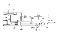
ロック機構90は、弁体40の回転を阻止する機構である。図3A乃至図3Cを参照して、ロック機構90について説明する。図3Aは、図2の2点鎖線で囲まれた領域Bの拡大図であり、ロック機構90によるロック状態を示す図である。図3Bは、図2の2点鎖線で囲まれた領域Bの拡大図であり、ロック機構90によるロックが解除された状態を示す図である。図3Cは、図3BのC-C矢視断面図である。
図3Aに示されるロック状態において、移動部材84(シールリング移動機構)の第1係合部94は、弁体40の第2係合部95に係合する。移動部材84の第1係合部94は、例えば、移動部材84の突出部分(X軸正の方向に向かって突出する部分)である。他方、弁体40の第2係合部95は、例えば、弁体40の表面に設けられた凹部である。図3Aに記載の例では、第1係合部94と、第2係合部95とが係合することにより、弁体40が、回転軸A1(Z軸)まわりに+R方向に回転することが阻止される。なお、第1係合部94、および、第2係合部95の形状を工夫することにより、第1係合部94と第2係合部95とが互いに係合する場合に、弁体40が、回転軸A1(Z軸)まわりに+R方向に回転することが阻止されるとともに、弁体40が、回転軸A1(Z軸)まわりに-R方向に回転することを阻止されるようにすることも可能である。
図3Aに記載の例では、流路開閉弁10は、ロック機構90を備える。このため、流路開閉弁10を作動させるための電源がOFFである時に、弁体4の移動が効果的に阻止される。流路開閉弁10が、ロケットの推進薬(例えば、液体水素)の流路に配置される場合には、流路開閉弁10を作動させるための電源がOFFである時に、推進薬の流路開閉弁10の下流側への洩れが効果的に抑制される。
図3Bに示されるように、ロック機構90によるロックを解除する際には、移動部材84は、弾性部材86の付勢力に抗して、X軸負の方向に移動される。移動部材84の移動に伴い、移動部材84によって保持されているシールリング70は、弁体40から離間する第2位置P2に移動する。また、移動部材84の移動に伴い、移動部材84の第1係合部94と、弁体40の第2係合部95との係合が解除される。その結果、弁体40が、回転軸A1(Z軸)まわりに回転することが可能となる。
図3Bに示される状態では、シールリング70は、弁体40から離間する第2位置P2に位置している。このため、流路開閉弁の開閉動作時における弁体40の回転負荷トルクが、効果的に低減される。
図3Cは、図3Bに示された弁体40のC-C矢視図である。図3Bおよび図3Cに記載の例では、第1係合部94は、シャフト50の回転軸A1に沿う方向に互いに離間配置される上側第1係合部94aおよび下側第1係合部94bを備える。また、図3Bおよび図3Cに記載の例では、第2係合部95は、シャフト50の回転軸A1(Z軸に平行な方向)に沿う方向に互いに離間配置される上側第2係合部95aおよび下側第2係合部95bを備える。このため、図3Bおよび図3Cに記載の例では、第1係合部94と第2係合部95との係合を、より強固にすることが可能である。
図3Cに示されるように、上側第2係合部95aおよび下側第2係合部95bは、弁体40の表面に設けられた凹部96(例えば、半リング状の凹部)の端面であってもよい。
図3Dは、上側第2係合部95aおよび下側第2係合部95bの変形例を示す。図3Dは、図3Bに示された弁体40(変形例)のC-C矢視図である。また、図3Eは、図3DのG-G矢視断面図である。図3B、図3Dおよび図3Eに記載の例では、第2係合部95は、シャフト50の回転軸A1(Z軸に平行な方向)に沿う方向に互いに離間配置される上側第2係合部95aおよび下側第2係合部95bを備える。このため、図3B、図3Dおよび図3Eに記載の例では、第1係合部94と第2係合部95との係合を、より強固にすることが可能である。なお、上側第2係合部95aおよび下側第2係合部95bは、弁体40の表面に設けられた凹部96の端面であってもよい。
図3C乃至図3Eに記載の例では、弁体40は、第2係合部95に連接する上段面に平滑な接触面97を有する。より具体的には、弁体40は、上側第2係合部95aに連設する上段面に、平滑な上側接触面97aを有し、弁体40は、下側第2係合部95bに連設する上段面に、平滑な下側接触面97bを有する。このため、振動等に起因して、弁体40の回転時に、第1係合部94が弁体40の接触面(97a、97b)に接触する場合であっても、接触面(97a、97b)が平滑であることにより、弁体40の回転が阻害されることがない。
図2乃至図3Eに記載の例では、シールリング移動機構80に、ロック機構90の第1係合部94が設けられている。このため、ロック機構90を作動させるために、新たに駆動機構等を設ける必要がない。その結果、流路開閉弁10が複雑化することが抑制される。
(ロック機構の変形例)
図4は、ロック機構の変形例を示す概略断面図である。図4に記載の例では、シールリング70に第1係合部94が設けられている点で、図2乃至図3Cに記載の例とは異なる。図4に記載の例は、その他の点では、図2乃至図3Cに記載の例と同様である。
図4は、ロック機構の変形例を示す概略断面図である。図4に記載の例では、シールリング70に第1係合部94が設けられている点で、図2乃至図3Cに記載の例とは異なる。図4に記載の例は、その他の点では、図2乃至図3Cに記載の例と同様である。
シールリング70の第1係合部94は、例えば、シールリング70の先端部分である。他方、弁体40の第2係合部95は、例えば、弁体40の表面に設けられた凹部である。図4に記載の例では、第1係合部94と、第2係合部95とが係合することにより、弁体40が、回転軸A1(Z軸)まわりに+R方向に回転することが阻止される。
図4に記載の例では、シールリング70に、ロック機構90の第1係合部94が設けられる。このため、ロック機構90を作動させるために、新たに駆動機構等を設ける必要がない。その結果、流路開閉弁10が複雑化することが抑制される。
(流路開閉弁のより詳細な説明)
図5乃至図7Cを参照して、流路開閉弁10について、より詳細に説明する。図5乃至図7Cにおいて、図2乃至図4に記載した部材と同じ機能を有する部材については、同一の図番が付されている。同一の図番が付された部材について、繰り返しの説明は、省略する。
図5乃至図7Cを参照して、流路開閉弁10について、より詳細に説明する。図5乃至図7Cにおいて、図2乃至図4に記載した部材と同じ機能を有する部材については、同一の図番が付されている。同一の図番が付された部材について、繰り返しの説明は、省略する。
図5は、流路開閉弁10を模式的に示す概略断面図である。図5に示されるように、流路開閉弁10は、弁ハウジング30と、弁体40(ボール弁体)と、シャフト50と、シャフトを回転させる第1駆動機構60と、シールリング70と、シールリング移動機構80と、ロック機構90とを備える。なお、軸受52は、シャフト50を回転可能に支持する軸受である。
(弁体40)
弁体40は、流路20に配置され、シャフト50とともに回転軸A1まわりに回転可能である。弁体40には、弁体内流路42が設けられていてもよい。弁体40が閉位置にある時、弁体内流路42は、流路20と不整合である。弁体40が開位置にある時、弁体内流路42は、流路20と整合する。
弁体40は、流路20に配置され、シャフト50とともに回転軸A1まわりに回転可能である。弁体40には、弁体内流路42が設けられていてもよい。弁体40が閉位置にある時、弁体内流路42は、流路20と不整合である。弁体40が開位置にある時、弁体内流路42は、流路20と整合する。
図5に記載の弁体40は、流路開閉弁10の閉鎖時に、シールリング70に着座する球面形状部40aを有する。球面形状部40aの曲率中心A2は、シャフトの回転軸A1上にない(図2に記載の例では、球面形状部の曲率中心A2は、シャフトの回転軸A1に対してY軸負の方向に偏心している。
(第1駆動機構)
第1駆動機構60は、モータ等の駆動源からの動力を用いてシャフト50を回転させることが可能である。シャフト50の回転により、弁体40は、閉位置と開位置との間で、回転移動する。なお、図5は、弁体40が閉位置にある状態を示している。
第1駆動機構60は、モータ等の駆動源からの動力を用いてシャフト50を回転させることが可能である。シャフト50の回転により、弁体40は、閉位置と開位置との間で、回転移動する。なお、図5は、弁体40が閉位置にある状態を示している。
第1駆動機構60は、例えば、モータ62と、モータ62の出力軸に接続されたボールねじ64と、ボールナット65と、第1リンク部材66と第2リンク部材67とを含むリンク機構とを備える。なお、軸受63は、ボールねじ64を回転可能に支持する軸受である。
図6Aおよび図6Bは、流路開閉弁10を模式的に示す概略斜視図である。図6Aは、流路開閉弁10が閉じている状態を示す概略斜視図であり、図6Bは、流路開閉弁10が開いている状態を示す概略斜視図である。図6Aを参照すると、第1リンク部材66の第1端部は、ボールナット65にピボット連結され、第1リンク部材66の第2端部66aは、第2リンク部材67の第1端部にピボット連結されている。また、第2リンク部材67の第2端部は、シャフト50に対して回転不能に連結されている。
流路開閉弁10が、図6Aに示される閉状態から、図6Bに示される開状態に変化する際の動作について説明する。図6Aに示される状態では、ボールナット65は、モータ62から最も離れた位置に位置する。図6Aに示される状態において、モータ62を駆動する。モータ62の駆動により、モータの出力軸が回転する。モータの出力軸の回転により、ボールねじ64が回転する。ボールねじ64の回転により、ボールナット65が、モータ62に近づく方向に移動する。ボールナット65が、モータ62に近づく方向に移動するにつれて、第1リンク部材66の第2端部66a(および、第2端部66aに連結された第2リンク部材67の第1端部)が、シャフト50の回転軸まわりに、+R方向(反時計回り)に回転する。第2リンク部材67の第1端部が、シャフト50の回転軸まわりに、+R方向に回転することにより、シャフト50が、シャフトの回転軸まわりに、+R方向に回転する。
流路開閉弁10が、図6Bに示される開状態から、図6Aに示される閉状態に変化する際の動作については、図6Aに示される閉状態から、図6Bに示される開状態に変化する際の動作の逆である。
なお、図5乃至図6Bに記載の例では、モータの出力軸と、シャフト50の回転軸A1とが同軸でない。このため、流体が液体水素、液体酸素、液体窒素等の極低温流体である場合であっても、極低温流体とモータとの間の熱伝達量を低減することが可能である。また、図6Aおよび図6Bに記載の例では、モータ62とシャフト50とが、リンク機構を介して動力伝達可能である。リンク機構が介在することにより、極低温流体とモータとの間の熱伝達量を低減することが可能である。
(シールリング移動機構80、および、ロック機構90)
図7A乃至図7Cを参照して、シールリング移動機構80およびロック機構90について説明する。図7Aは、図5の2点鎖線で囲まれた領域Dの拡大図であり、シールリング70が弁体40に接触するとともに、弁体40がロック機構90によりロックされている状態を示す図である。図7Bは、図5の2点鎖線で囲まれた領域Dの拡大図であり、シールリング70が弁体40に接触するとともに、弁体40のロックが解除されている状態を示す図である。図7Cは、図5の2点鎖線で囲まれた領域Dの拡大図であり、シールリング70が弁体40から離間するとともに、弁体40のロックが解除されている状態を示す図である。
図7A乃至図7Cを参照して、シールリング移動機構80およびロック機構90について説明する。図7Aは、図5の2点鎖線で囲まれた領域Dの拡大図であり、シールリング70が弁体40に接触するとともに、弁体40がロック機構90によりロックされている状態を示す図である。図7Bは、図5の2点鎖線で囲まれた領域Dの拡大図であり、シールリング70が弁体40に接触するとともに、弁体40のロックが解除されている状態を示す図である。図7Cは、図5の2点鎖線で囲まれた領域Dの拡大図であり、シールリング70が弁体40から離間するとともに、弁体40のロックが解除されている状態を示す図である。
(シールリング移動機構80)
シールリング移動機構80は、シールリング70を移動させる。シールリング移動機構80は、シールリング70を、X軸方向に沿って移動させる。シールリング移動機構80は、シールリング70を、弁体40に接触可能な第1位置P1と、弁体40から離間する第2位置P2との間で移動させる。なお、図7Aおよび図7Bは、シールリング70が第1位置P1にある状態を示している。
シールリング移動機構80は、シールリング70を移動させる。シールリング移動機構80は、シールリング70を、X軸方向に沿って移動させる。シールリング移動機構80は、シールリング70を、弁体40に接触可能な第1位置P1と、弁体40から離間する第2位置P2との間で移動させる。なお、図7Aおよび図7Bは、シールリング70が第1位置P1にある状態を示している。
シールリング移動機構80は、シールリング70を移動させる機構であれば、どのような機構であってもよい。図7Aに記載の例では、シールリング移動機構80は、移動部材84と、移動部材84を移動させる第2駆動機構とを備える。図7Aに記載の例では、第2駆動機構は、ソレノイド82である。代替的に、第2駆動機構は、流体作動式のアクチュエータであってもよい。
移動部材84は、移動部材本体84Aを備える。移動部材本体84Aは、第2駆動機構の作用によって、X軸正の方向またはX軸負の方向に移動する。より具体的には、移動部材本体84Aは、ソレノイド82に流れる電流に応答して、X軸正の方向またはX軸負の方向に移動する。
図7Aに記載の例では、移動部材本体84Aは、アーマチャ84A1と、アーマチャ84A1に対して移動不能に固定された突出部材84A2とを備える。突出部材84A2は、例えば、環状の部材である。
移動部材本体84A(移動部材本体の先端部)は、シールリング70に係合可能なシールリング係合部84aを備える。シールリング係合部84aは、移動部材本体84Aが、X軸負の方向(換言すれば、弁体40から離間する方向)に移動する時、シールリング70に係合する。シールリング70は、シールリング係合部84aと係合した後、移動部材本体84Aとともに、X軸負の方向(換言すれば、弁体40から離間する方向)に移動することが可能である(必要であれば、図7Cを参照)。
移動部材84は、移動部材本体84Aに対して相対移動可能なスライダ84Bと、移動部材本体84Aとスライダ84Bとの間に配置される第1弾性部材84C(例えば、コイルばね)と、弁ハウジング30とスライダ84Bとの間に配置される第2弾性部材84D(例えば、皿ばね)とを備える。
移動部材本体84Aは、ソレノイド82に電流が流れない時(換言すれば、第2駆動機構が非作動状態の時)、第1弾性部材84Cおよび第2弾性部材84Dによって、X軸正の方向(すなわち、弁体40に向かう方向)に向かって付勢される。
スライダ84Bは、第2弾性部材84Dによって、X軸正の方向(すなわち、弁体40に向かう方向)に向かって付勢される。スライダ84B(スライダの先端部)は、シールリング70に係合可能なシールリング係合部84bを備える。第2弾性部材84Dによって付勢されるスライダ84Bは、シールリング係合部84bを介して、シールリング70を弁体40に対して押圧する。換言すれば、第2弾性部材84Dによる付勢力がスライダ84Bに作用することによって、シールリング70は、弁体40の球面形状部40aに対して効果的に押圧される。シールリング70が、弁体40の球面形状部40aに対して効果的に押圧されることにより、弁体40がシールリング70によって確実にシールされる。
第1弾性部材84Cは、移動部材本体84Aとスライダ84Bとの間に配置される。より具体的には、第1弾性部材84Cは、移動部材本体84Aに設けられた弾性部材受け部材84a1と、スライダ84Bの側方突出部84b1との間に配置される。
第2弾性部材84Dは、弁ハウジング30とスライダ84Bとの間に配置される。より具体的には、第2弾性部材84Dは、弁ハウジング30に設けられた弾性部材受け部材31と、スライダ84Bの側方突出部84b1との間に配置される。なお、第2弾性部材84Dは、複数の皿バネを積み重ねることによって構成される弾性部材であってもよい。
なお、図7Aに記載の例では、スライダ84Bの側方突出部84b1は、第1弾性部材84Cと第2弾性部材84Dとの間で挟まれている。
また、図7Aに記載の例では、第2弾性部材84Dの弾性率は、第1弾性部材84Cの弾性率よりも大きい。このため、移動部材本体84Aが、X軸負の方向に向かって移動する時、移動部材本体84Aのシールリング係合部84aとシールリング70とが係合するまでの間は、主として、第1弾性部材84Cが収縮することとなる。他方、移動部材本体84Aが、X軸負の方向に向かって移動する時、移動部材本体84Aのシールリング係合部84aとシールリング70とが係合した後は、第2弾性部材84Dが収縮することとなる。
(ロック機構90)
ロック機構90は、弁体40の回転を阻止する機構である。ロック機構90は、シールリング移動機構80(より具体的には、移動部材84あるいは移動部材本体84A)に設けられる第1係合部94と、弁体40に設けられる第2係合部95とを備える。
ロック機構90は、弁体40の回転を阻止する機構である。ロック機構90は、シールリング移動機構80(より具体的には、移動部材84あるいは移動部材本体84A)に設けられる第1係合部94と、弁体40に設けられる第2係合部95とを備える。
図7Aに示されるロック状態において、移動部材84(シールリング移動機構)の第1係合部94は、弁体40の第2係合部95に係合する。移動部材84の第1係合部94は、例えば、移動部材84の突出部分(X軸正の方向に向かって突出する部分)である。他方、弁体40の第2係合部95は、例えば、弁体40の表面に設けられた凹部である。図7Aに記載の例では、第1係合部94と、第2係合部95とが係合することにより、弁体40が、回転軸A1(Z軸)まわりに+R方向に回転することが阻止される。
図7Aに示されるように、流路開閉弁10は、ロック機構90を備える。このため、流路開閉弁10を作動させるための電源がOFFである時に、弁体4が開方向に移動することが効果的に阻止される。
(シールリングの移動動作、および、ロック解除動作)
次に、図7A乃至図7Cを参照して、シールリングの移動動作、および、ロック解除動作について説明する。
次に、図7A乃至図7Cを参照して、シールリングの移動動作、および、ロック解除動作について説明する。
図7Aに記載の状態において、ソレノイド82には電流が流れていない(換言すれば、図7Aに記載の状態において、第2駆動機構は、非作動状態である。)。図7Aに記載の状態では、スライダ84Bおよびスライダ84Bによって押圧されるシールリング70が、第2弾性部材84Dによって、弁体40に向かう方向に向けて付勢される。その結果、シールリング70が、弁体40の球面形状部40aに密着する。
また、図7Aに記載の状態では、移動部材本体84Aが、第1弾性部材84Cによって、弁体40に向かう方向に向けて付勢される。そして、移動部材本体84Aに設けられる第1係合部94と、弁体40に設けられる第2係合部95とが係合する。その結果、弁体40の回転(シャフト50の回転軸まわりの回転)が効果的に阻止される。
図7Aに記載の状態において、ソレノイド82に電流を流すことを想定する(換言すれば、図7Aに記載の状態において、第2駆動機構を作動状態にすることを想定する。)。第2駆動機構の作動により、移動部材本体84Aは、弁体40から離間する方向(X軸負の方向)に移動する。移動部材本体84Aの移動に伴い、第1弾性部材84Cは収縮する。また、移動部材本体84Aの移動に伴い、移動部材本体84Aに設けられる第1係合部94と、弁体40に設けられる第2係合部95との係合が解除される。図7Bは、第1係合部94と第2係合部95との係合が解除された後の状態を示す。なお、第2弾性部材84Dの弾性率は、第1弾性部材84Cの弾性率よりも大きいため、第2弾性部材84Dの収縮量は、第1弾性部材84Cの収縮量よりも小さい。その結果、図7Bに記載の状態では、シールリング70が、弁体40の球面形状部40aに密着する状態は維持される。
図7Bに記載の状態において、ソレノイド82に電流を流すことにより、移動部材本体84Aを、弁体40から離間する方向(X軸負の方向)に、更に移動させることを想定する。図7Bに記載の状態では、移動部材本体84Aのシールリング係合部84aがシールリング70と係合している。このため、移動部材本体84Aを、弁体40から離間する方向(X軸負の方向)に更に移動させると、移動部材本体84Aは、シールリング70を介して、スライダ84Bを押圧することとなる。その結果、スライダ84Bおよびシールリング70は、弁体40から離間する方向(X軸負の方向)に移動する。シールリング70の移動に伴い、シールリング70は、弁体40から離間する。また、スライダ84Bの移動に伴い、第2弾性部材84Dは収縮する。図7Cは、シールリング70が、弁体40から離間した後の状態を示す。
図7Cに記載の状態では、シールリング70が、弁体40から離間している、図7Cに記載の状態において、弁体40を回転させれば(換言すれば、シャフト50を回転させれば)、流路開閉弁10を開状態にすることが可能である。また、図7Cに記載の状態では、弁体40とシールリング70とが互いに接触していないため、弁体40を回転させる回転負荷トルクを抑制することが可能である。
図6乃至図7Cに記載の例では、シールリング移動機構80に、ロック機構90の第1係合部94が設けられている。このため、ロック機構90を作動させるために、新たに駆動機構等を設ける必要がない。その結果、流路開閉弁10が複雑化することが抑制される。
なお、図7Cに記載の状態から、図7Aに記載の状態(シールリング70が弁体40に接触するとともに、弁体40がロック機構90によりロックされている状態)に戻すためには、例えば、弁体40を閉位置に移動させた後、ソレノイド82に供給する電流を遮断すればよい(換言すれば、第2駆動機構を、非作動状態にすればよい。)。
なお、図7Aにおいて、シール部材100は、スライダ84Bと弁ハウジング30との間をシールする部材である。
(シム部材)
図7Dは、図7Aに記載されたシールリング移動機構およびロック機構の変形例を示す。図7Dは、図5の2点鎖線で囲まれた領域Dの拡大図であり、シールリング70が弁体40に接触するとともに、弁体40がロック機構90によりロックされている状態を示す図である。図7Dに記載の例は、移動部材84(より具体的には、移動部材本体84A)と弁ハウジング30との間に、シム部材200が配置されている点で、図7Aに記載の例と異なる。図7Dに記載の例は、その他の点では、図7Aに記載の例と同様である。
図7Dは、図7Aに記載されたシールリング移動機構およびロック機構の変形例を示す。図7Dは、図5の2点鎖線で囲まれた領域Dの拡大図であり、シールリング70が弁体40に接触するとともに、弁体40がロック機構90によりロックされている状態を示す図である。図7Dに記載の例は、移動部材84(より具体的には、移動部材本体84A)と弁ハウジング30との間に、シム部材200が配置されている点で、図7Aに記載の例と異なる。図7Dに記載の例は、その他の点では、図7Aに記載の例と同様である。
図7Dに記載の例では、シム部材200が配置されることにより、第1係合部94と第2係合部95との間の係合面積を調整することが可能である。このため、ロック機構90によるロック時(第1係合部94と第2係合部95との係合時)に、流体圧が弁体40に作用することにより発生するトルクの大きさに応じて、適切な係合面積を確保することが可能となる。すなわち、シム部材200の厚さ、あるいは、シム部材200の枚数を調整することにより、適切な係合面積を確保することが可能となる。
(第1係合部および第2係合部の一例)
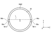
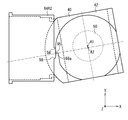
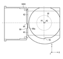
図8Aおよび図8Bは、第1係合部94および第2係合部95の一例を示す。図8Aは、移動部材本体84Aである突出部材84A2、および、弁体40を、Z軸正の方向からZ軸負の方向に向けて見た概略平面図である。図8Bは、移動部材本体84Aである突出部材84A2を、X軸負の方向からX軸正の方向に向けて見た概略側面図である。図8Aおよび図8Bにおいて、図2乃至図7Dに記載した部材と同じ機能を有する部材については、同一の図番が付されている。同一の図番が付された部材について、繰り返しの説明は、省略する。
図8Aおよび図8Bは、第1係合部94および第2係合部95の一例を示す。図8Aは、移動部材本体84Aである突出部材84A2、および、弁体40を、Z軸正の方向からZ軸負の方向に向けて見た概略平面図である。図8Bは、移動部材本体84Aである突出部材84A2を、X軸負の方向からX軸正の方向に向けて見た概略側面図である。図8Aおよび図8Bにおいて、図2乃至図7Dに記載した部材と同じ機能を有する部材については、同一の図番が付されている。同一の図番が付された部材について、繰り返しの説明は、省略する。
図8Aおよび図8Bに記載の例では、突出部材84A2(移動部材本体84A)の先端部に、弁体40に向けて突出する2つの突出部98を備える。そして、2つの突出部98のうちの上側の突出部98-1(Z軸正の方向側の突出部)が、上側第1係合部94aを含む。また、2つの突出部98のうちの下側の突出部98-2(Z軸負の方向側の突出部)が、下側第1係合部94bを含む。突出部材84A2(移動部材本体84A)が、シャフト50の長手方向に平行な方向に沿って離間して配置された2つの第1係合部(複数の第1係合部94)を備えることにより、弁体40のロック時に、弁体40の回転が確実に阻止される。
また、図8Bに記載の例では、上側第1係合部94aと下側係合部94bとを結ぶ仮想直線Lが、流路20の長手方向に垂直な断面における流路20の中心部(中心部には、中心と、その近傍領域が含まれる)を通るように、上側第1係合部94aと下側係合部94bとが配置されている。当該配置を採用することにより、偏心して配置された弁体40(A1≠A2であるように配置された弁体40)に向けて突出する突出部98の突出量を小さくすることが可能となる。換言すれば、上側第1係合部94aと下側係合部94bについて、図8Bに記載の例と異なる配置を採用する場合には、弁体40に設けられた第2係合部95との係合を実現するため、突出部98の突出量を相対的に大きくする必要がある。
図8Aおよび図8Bに記載の例では、各突出部98の表面のうち弁体40に面する表面は、傾斜角度が一定あるいは傾斜角度が連続的に変化する滑らかな表面98aである。各突出部の表面のうち弁体40に面する表面を、傾斜角度が一定あるいは傾斜角度が連続的に変化する表面98aとすることにより、弁体40の回転を円滑にすることが可能である。すなわち、振動等に起因して、第2係合部95が、表面98aに一時的に接触する場合においても、弁体40の回転が阻害されることがない。
なお、図8Aに記載の例では、弁体40の球面形状部の曲率中心A2は、シャフト50の回転軸A1に対して、Y軸負の方向に偏心している。
なお、図8Aおよび図8Bは、突出部材84A2が、図7Aに示される状態に位置する時に対応する図である。突出部材84A2が、図7Bで示される位置に移動した後(ロックが解除される時)、弁体40を回転軸A1まわりに回転させることが可能である。図8Cは、弁体40が回転軸A1まわりに、10°回転した後の状態を示す。図8Cに記載の状態では、流路開閉弁は、閉状態にある。その後、突出部材84A2が、図7Cに示される位置に移動するとともに、弁体が回転軸A1まわりに、さらに回転することを想定する。図7Dは、弁体40が、図8Aに示される位置から、回転軸A1まわりに、90°回転した後の状態を示す。図8Dに記載の状態では、突出部材84A2が、弁体40に接触していない。このため、弁体40の回転に要するトルクを低減することが可能である。
本発明は上記各実施形態に限定されず、本発明の技術思想の範囲内において、各実施形態は適宜変形又は変更され得ることは明らかである。また、各実施形態又は変形例で用いられる種々の技術は、技術的矛盾が生じない限り、他の実施形態又は変形例にも適用可能である。
本出願は、2015年2月27日に出願された日本国特許出願第2015-38985号を基礎とする優先権を主張し、当該基礎出願の開示の全てを引用により本出願に取り込む。
Claims (11)
- 流路を有する弁ハウジングと、
前記流路に配置され、シャフトとともに回転可能な弁体と、
前記シャフトを回転させる第1駆動機構と、
前記流路に配置され、前記弁体が着座するシールリングと、
前記シールリングを、前記弁体に接触可能な第1位置と前記弁体から離間する第2位置との間で移動させるシールリング移動機構と、
前記弁体の回転を阻止するロック機構と
を具備し、
前記ロック機構は、
前記シールリングまたは前記シールリング移動機構に設けられる、第1係合部と、
前記弁体に設けられる第2係合部と、
を備える
流路開閉弁。 - 前記弁体は、前記シールリングに着座する球面形状部を備える
請求項1に記載の流路開閉弁。 - 前記第1係合部は、前記シャフトの長手方向に平行な方向に沿って互いに離間して配置された上側第1係合部と下側第1係合部とを備える
請求項2に記載の流路開閉弁。 - 前記上側第1係合部と前記下側係合部とを結ぶ仮想直線は、前記流路の長手方向に垂直な断面における前記流路の中心部を通る
請求項3に記載の流路開閉弁。 - 前記球面形状部の曲率中心は、前記シャフトの回転軸上にない
請求項2乃至4のいずれか一項に記載の流路開閉弁。 - 前記シールリング移動機構は、
前記弁ハウジングに対して相対移動可能であり、前記シールリングに係合可能な移動部材と、
前記移動部材を移動させる第2駆動機構と
を備える
請求項1乃至5のいずれか一項に記載の流路開閉弁。 - 前記第1係合部は、前記移動部材に設けられる
請求項6に記載の流路開閉弁。 - 前記移動部材は、前記第2駆動機構によって移動される移動部材本体と、
前記移動部材本体に対して相対移動可能なスライダと、
前記移動部材本体と前記スライダとの間に配置される第1弾性部材と
を備える
請求項6または7に記載の流路開閉弁。 - 前記シールリング移動機構は、前記弁ハウジングと前記スライダとの間に配置される第2弾性部材を備え、
前記第2弾性部材の弾性率は、前記第1弾性部材の弾性率よりも大きい
請求項8に記載の流路開閉弁。 - 前記移動部材と前記弁ハウジングとの間に配置されるシム部材を備える
請求項6乃至9のいずれか一項に記載の流路開閉弁。 - 前記第1係合部を備える突出部の表面のうち前記弁体に面する表面は、傾斜角度が一定あるいは傾斜角度が連続的に変化する表面である
請求項1乃至10のいずれか一項に記載の流路開閉弁。
Applications Claiming Priority (2)
| Application Number | Priority Date | Filing Date | Title |
|---|---|---|---|
| JP2015-038985 | 2015-02-27 | ||
| JP2015038985A JP2016161005A (ja) | 2015-02-27 | 2015-02-27 | 流路開閉弁 |
Publications (1)
| Publication Number | Publication Date |
|---|---|
| WO2016136643A1 true WO2016136643A1 (ja) | 2016-09-01 |
Family
ID=56788694
Family Applications (1)
| Application Number | Title | Priority Date | Filing Date |
|---|---|---|---|
| PCT/JP2016/054977 Ceased WO2016136643A1 (ja) | 2015-02-27 | 2016-02-22 | 流路開閉弁 |
Country Status (2)
| Country | Link |
|---|---|
| JP (1) | JP2016161005A (ja) |
| WO (1) | WO2016136643A1 (ja) |
Cited By (2)
| Publication number | Priority date | Publication date | Assignee | Title |
|---|---|---|---|---|
| JP2019065984A (ja) * | 2017-10-02 | 2019-04-25 | ミネベアミツミ株式会社 | ボールバルブ |
| CN115059773A (zh) * | 2022-07-19 | 2022-09-16 | 超达阀门集团股份有限公司 | 一种超低温半球阀 |
Citations (3)
| Publication number | Priority date | Publication date | Assignee | Title |
|---|---|---|---|---|
| JPS5028026A (ja) * | 1973-06-15 | 1975-03-22 | ||
| JPS537841A (en) * | 1976-07-09 | 1978-01-24 | Const Metaritsuku Dou Burobuan | Cock providing rotary valve and slidable valve seat |
| JPH0384269A (ja) * | 1989-08-28 | 1991-04-09 | Kurimoto Ltd | 球形弁の起動機構 |
-
2015
- 2015-02-27 JP JP2015038985A patent/JP2016161005A/ja active Pending
-
2016
- 2016-02-22 WO PCT/JP2016/054977 patent/WO2016136643A1/ja not_active Ceased
Patent Citations (3)
| Publication number | Priority date | Publication date | Assignee | Title |
|---|---|---|---|---|
| JPS5028026A (ja) * | 1973-06-15 | 1975-03-22 | ||
| JPS537841A (en) * | 1976-07-09 | 1978-01-24 | Const Metaritsuku Dou Burobuan | Cock providing rotary valve and slidable valve seat |
| JPH0384269A (ja) * | 1989-08-28 | 1991-04-09 | Kurimoto Ltd | 球形弁の起動機構 |
Cited By (2)
| Publication number | Priority date | Publication date | Assignee | Title |
|---|---|---|---|---|
| JP2019065984A (ja) * | 2017-10-02 | 2019-04-25 | ミネベアミツミ株式会社 | ボールバルブ |
| CN115059773A (zh) * | 2022-07-19 | 2022-09-16 | 超达阀门集团股份有限公司 | 一种超低温半球阀 |
Also Published As
| Publication number | Publication date |
|---|---|
| JP2016161005A (ja) | 2016-09-05 |
Similar Documents
| Publication | Publication Date | Title |
|---|---|---|
| US10801627B2 (en) | Valve seats, valve assemblies, and related methods | |
| CN101644338B (zh) | 蝶式压力控制阀 | |
| JP6014476B2 (ja) | バタフライ式圧力制御バルブ | |
| US7871061B1 (en) | Dual spreading link for gate valves | |
| CN105209807A (zh) | 用于热管理阀的低阻力密封方法 | |
| JP2013537295A (ja) | 活荷重をシールに提供するための弁帽装置 | |
| WO2013129140A1 (ja) | てこ式切替弁 | |
| JP2018123856A (ja) | バルブ装置 | |
| JP2016161005A (ja) | 流路開閉弁 | |
| US9046098B2 (en) | Face sealing annular valve for a fluid-working machine | |
| KR100367532B1 (ko) | 삼차 편심구조를 갖는 메탈시트형 버터플라이밸브 | |
| US20180347706A1 (en) | Shaft Sealing Device | |
| US6717332B2 (en) | Apparatus having a support structure and actuator | |
| US6739574B1 (en) | Valve piezo electric | |
| JP5850876B2 (ja) | ボールバルブ | |
| US5713556A (en) | Composite-action butterfly valve | |
| WO2010058726A1 (ja) | ダイヤフラムバルブ | |
| EP2676056A1 (en) | Valve assembly | |
| US20030026034A1 (en) | Positioning rotary actuators | |
| JP3550513B2 (ja) | 二重偏心構造のバタフライ弁の弁体 | |
| JP2018112260A (ja) | 真空バルブ | |
| EP1878956B1 (en) | Valve device | |
| JP6450694B2 (ja) | 流体制御弁 | |
| US8807526B2 (en) | Butterfly valve having moving disc | |
| JP2009185999A (ja) | バルブ装置 |
Legal Events
| Date | Code | Title | Description |
|---|---|---|---|
| 121 | Ep: the epo has been informed by wipo that ep was designated in this application |
Ref document number: 16755389 Country of ref document: EP Kind code of ref document: A1 |
|
| NENP | Non-entry into the national phase |
Ref country code: DE |
|
| 122 | Ep: pct application non-entry in european phase |
Ref document number: 16755389 Country of ref document: EP Kind code of ref document: A1 |