WO2016136504A1 - 圧縮機及び冷凍サイクル装置 - Google Patents
圧縮機及び冷凍サイクル装置 Download PDFInfo
- Publication number
- WO2016136504A1 WO2016136504A1 PCT/JP2016/054160 JP2016054160W WO2016136504A1 WO 2016136504 A1 WO2016136504 A1 WO 2016136504A1 JP 2016054160 W JP2016054160 W JP 2016054160W WO 2016136504 A1 WO2016136504 A1 WO 2016136504A1
- Authority
- WO
- WIPO (PCT)
- Prior art keywords
- compressor
- refrigerant
- suction
- suction pipe
- compression mechanism
- Prior art date
- Legal status (The legal status is an assumption and is not a legal conclusion. Google has not performed a legal analysis and makes no representation as to the accuracy of the status listed.)
- Ceased
Links
Images

Classifications
-
- F—MECHANICAL ENGINEERING; LIGHTING; HEATING; WEAPONS; BLASTING
- F04—POSITIVE - DISPLACEMENT MACHINES FOR LIQUIDS; PUMPS FOR LIQUIDS OR ELASTIC FLUIDS
- F04B—POSITIVE-DISPLACEMENT MACHINES FOR LIQUIDS; PUMPS
- F04B39/00—Component parts, details, or accessories, of pumps or pumping systems specially adapted for elastic fluids, not otherwise provided for in, or of interest apart from, groups F04B25/00 - F04B37/00
- F04B39/12—Casings; Cylinders; Cylinder heads; Fluid connections
-
- F—MECHANICAL ENGINEERING; LIGHTING; HEATING; WEAPONS; BLASTING
- F04—POSITIVE - DISPLACEMENT MACHINES FOR LIQUIDS; PUMPS FOR LIQUIDS OR ELASTIC FLUIDS
- F04C—ROTARY-PISTON, OR OSCILLATING-PISTON, POSITIVE-DISPLACEMENT MACHINES FOR LIQUIDS; ROTARY-PISTON, OR OSCILLATING-PISTON, POSITIVE-DISPLACEMENT PUMPS
- F04C29/00—Component parts, details or accessories of pumps or pumping installations, not provided for in groups F04C18/00 - F04C28/00
- F04C29/12—Arrangements for admission or discharge of the working fluid, e.g. constructional features of the inlet or outlet
-
- F—MECHANICAL ENGINEERING; LIGHTING; HEATING; WEAPONS; BLASTING
- F25—REFRIGERATION OR COOLING; COMBINED HEATING AND REFRIGERATION SYSTEMS; HEAT PUMP SYSTEMS; MANUFACTURE OR STORAGE OF ICE; LIQUEFACTION SOLIDIFICATION OF GASES
- F25B—REFRIGERATION MACHINES, PLANTS OR SYSTEMS; COMBINED HEATING AND REFRIGERATION SYSTEMS; HEAT PUMP SYSTEMS
- F25B1/00—Compression machines, plants or systems with non-reversible cycle
Definitions
- Embodiments of the present invention relate to a compressor and a refrigeration cycle apparatus.
- compressors that compress a gas refrigerant are known to use the suction supercharging effect.
- the suction supercharging effect that increases the amount of gas refrigerant sucked into the compression mechanism part by the resonance action of the pressure wave due to the pulsation of the gas refrigerant generated when the gas refrigerant is sucked into the compression mechanism part is utilized. It increases capacity.
- the maximum capacity of the compressor can be increased, and the capacity variable range from the minimum capacity to the maximum capacity can be increased.
- m is a function of 1, 2, 3,...
- C is the speed of sound transmitted through the gas refrigerant (m / s)
- L is the length of the suction pipe (m) through which the gas refrigerant flows
- A is the cross-sectional area (m 2 ) of the suction pipe.
- the resonance peak rotational speed f at which a suction supercharging effect can be obtained is increased in the same configuration as that in the case of using a conventional refrigerant, and compression is performed. It may shift to a higher rotation side than the allowable rotation speed range of the machine. Therefore, when using a gas refrigerant that increases the speed C of the transmitted sound, L + (V / A) needs to be increased in order to keep the resonance peak rotational speed f within the allowable rotational speed range of the compressor. There is.
- the capacity can be increased, but the work amount also increases, and the coefficient of performance (hereinafter referred to as COP) may be lower than when the suction supercharging effect is not used.
- An object of an embodiment of the present invention is to obtain a compressor and a refrigeration isle device that can prevent a reduction in the COP of the compressor when using the suction supercharging effect of the gas refrigerant to the compression mechanism.
- the rotary compressor includes a compression mechanism section, an electric motor section that drives the compression mechanism section, and a suction pipe that communicates with a suction port of the compression mechanism section.
- the R32 refrigerant or the R32 refrigerant is 70 weights.
- a compressor that compresses a mixed refrigerant containing at least When the displacement volume of the compression mechanism unit is V with the unit m 3 , the cross-sectional area of the suction pipe is A with the unit m 2 , and the length of the suction pipe with the unit m is L, A relational expression of 2 ⁇ L / (V / A) ⁇ 3 is established.
- FIG. 1 shows the overall configuration of a refrigeration cycle apparatus 1, which has a compressor body 2 and an accumulator 3 that is arranged separately from the compressor body 2.
- the rotary compressor 4 that compresses the gas refrigerant accommodated in the compressor main body 2 and the high-pressure and high-temperature gas refrigerant that is connected to the compressor main body 2 and discharged from the compressor main body 2 are condensed into a liquid.
- the accumulator 3 has an introduction port 3a into which the gas refrigerant evaporated by the evaporator 7 is introduced.
- the liquid refrigerant contained in the gas refrigerant introduced from the introduction port 3a is separated in the accumulator 3.
- the accumulator 3 and the compressor body 2 are connected by a suction pipe 8 through which only a gas refrigerant flows.
- the suction pipe 8 is provided through the bottom of the accumulator 3, one end is opened above the inside of the accumulator 3, and the other end is communicated with a suction port of a compression mechanism section described later provided in the compressor body 2. Yes.
- R32 refrigerant made of hydrofluorocarbon (HFC) or a mixed refrigerant containing 70 wt% or more of R32 refrigerant is used, and the gas refrigerant is compressed by the rotary compressor 4.
- the compressor body 2 has a sealed case 9 formed in a cylindrical shape, and an electric motor unit 10 and a compression mechanism unit 11 that is driven by the electric motor unit 10 and compresses a gas refrigerant are accommodated in the sealed case 9.
- the electric motor unit 10 and the compression mechanism unit 11 are arranged such that the electric motor unit 10 is disposed above and the compression mechanism unit 11 is disposed below, and the electric motor unit 10 and the compression mechanism unit 11 extend in the vertical direction and rotate around the axis.
- Lubricating oil 13 is stored at the bottom of the sealed case 9.
- the electric motor unit 10 has a rotor 14 fixed to the rotary shaft 12 and a stator 15 fixed inside the sealed case 9 and arranged at a position surrounding the rotor 14.
- the rotor 14 is provided with a permanent magnet (not shown), and the stator 15 is wound with a coil (not shown).
- the rotor 14 and the rotating shaft 12 rotate around the axis of the rotating shaft 12 by energizing the coil.
- the compression mechanism 11 has a cylinder 16 that is fixed to the inner side of the sealed case 9 and that is open at both ends in the vertical direction.
- a main bearing 17 that functions as a closing member that closes the upper end side of the cylinder 16 and a sub-bearing 18 that functions as a closing member that closes the lower end side of the cylinder 16 are fixed to the cylinder 16.
- a cylinder chamber 19 is formed in the cylinder 16 by closing both end surfaces of the cylinder 16 with the main bearing 17 and the auxiliary bearing 18.
- the rotary shaft 12 is inserted into the cylinder chamber 19, and the rotary shaft 12 is pivotally supported by the main bearing 17 and the auxiliary bearing 18 so as to be rotatable around the axis.
- An eccentric portion 20 is formed in a portion of the rotary shaft 12 located in the cylinder chamber 19, and a roller 21 is fitted to the eccentric portion 20.
- the roller 21 rotates eccentrically in the cylinder chamber 19 as the rotary shaft 12 rotates about the axis.
- a blade groove (not shown) is formed in the cylinder 16, and a blade (not shown) formed in a plate shape is accommodated in the blade groove so as to be reciprocally movable.
- a spring (not shown) is accommodated in the inner part of the blade groove, and the blade is biased toward the roller 21 by the spring, and the tip of the blade is in contact with the outer peripheral surface of the roller 21. Then, when the tip of the blade comes into contact with the outer peripheral surface of the roller 21, the cylinder chamber 19 is divided into a suction chamber 22 that sucks in the gas refrigerant and a compression chamber (not shown) that compresses the sucked gas refrigerant. ing.
- the suction of the gas refrigerant from the accumulator 3 into the suction chamber 22 is performed via the suction pipe 8 and the suction port 23 formed in the cylinder 16 and connected to the end of the suction pipe 8. .
- the main bearing 17 is formed with a discharge hole 24 through which the gas refrigerant compressed in the compression chamber is discharged, and a discharge valve 25 for opening and closing the discharge hole 24 is attached.
- a discharge muffler 26 that covers the discharge hole 24 and the discharge valve 25 is attached to the main bearing 17.
- the discharge muffler 26 is formed with an outflow hole 27 through which the gas refrigerant discharged from the discharge hole 24 into the discharge muffler 26 flows into the sealed case 9.
- V, A, and L are set so that a relational expression of 2 ⁇ L / (V / A) ⁇ 3 holds. Furthermore, V, A, and L are set so that the relational expression of 0.4 ⁇ L + (V / A) ⁇ 0.6 holds.
- the discharge valve 25 When the pressure of the compressed gas refrigerant reaches the set pressure, the discharge valve 25 is opened, and the gas refrigerant is discharged from the discharge hole 24 into the discharge muffler 26. The gas refrigerant discharged into the discharge muffler 26 flows out from the outflow hole 27 into the sealed case 9.
- the gas refrigerant that has flowed into the sealed case 9 flows in the order of the condenser 5, the expansion device 6, and the evaporator 7, returns to the rotary compressor 4, and performs heat dissipation in the condenser 5 and heat absorption in the evaporator 7.
- the refrigeration cycle is executed.
- m is a function of 1, 2, 3,...
- C is the speed of sound (m / s) transmitted through the gas refrigerant.
- the speed C of sound transmitted through the gas refrigerant is about 1.3 times faster than the R410A refrigerant made of hydrofluorocarbon (HFC), which is widely used in the past, in the case of R32 refrigerant or a mixed refrigerant containing 70 wt% or more of R32 refrigerant. Become.
- HFC hydrofluorocarbon
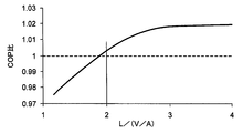
- FIG. 2 shows the suction supercharging effect when the displacement volume of the compression mechanism is V, the cross-sectional area of the suction pipe is A, the length of the suction pipe is L, and the speed of sound flowing through the gas refrigerant used is different.
- It is a graph which shows the change of COP according to the ratio of L and V / A at the time of driving
- the horizontal axis represents the ratio of L and V / A
- the vertical axis represents the COP ratio.
- the COP ratio is the resonance when using L32 refrigerant and increasing L + (V / A) so that the resonance peak rotational speed f at which the suction supercharging effect is obtained is the same as when using the R410A refrigerant.
- This is the ratio of the COP at the peak rotational speed f to the COP when operating without using the suction supercharging effect (the COP when operating without using the suction supercharging effect is 1).
- operating without utilizing a suction supercharging effect is made the same when using a suction supercharging effect.
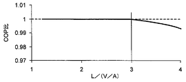
- FIG. 3 shows the suction supercharging effect when the displacement volume of the compression mechanism is V, the cross-sectional area of the suction pipe is A, the length of the suction pipe is L, and the speed of sound flowing through the gas refrigerant used is different. It is a graph explaining the change of COP according to the ratio of L and V / A at the time of driving
- the horizontal axis represents the ratio of L and V / A
- the vertical axis represents the COP ratio.
- the COP ratio is the resonance when using L32 refrigerant and increasing L + (V / A) so that the resonance peak rotational speed f at which the suction supercharging effect is obtained is the same as when using the R410A refrigerant.
- This is the ratio of the COP at a speed lower than the peak speed f (the speed at the intermediate capacity) to the COP when operating without using the suction supercharging effect (when operating without using the suction supercharging effect) Of COP of 1).
- V / A corresponding to the flow velocity of the gas refrigerant flowing in the suction pipe 8 is small and the length L of the suction pipe 8 is long.
- the time required for the gas to pass through the suction pipe 8 is lengthened, and the gas refrigerant is heated by the heat from the surroundings while flowing in the suction pipe 8, and the gas refrigerant before compression is warmed, thereby reducing the capacity. This is because it occurs.
- L / (V / A) 3
- the time required for the gas refrigerant to pass through the suction pipe 8 is shortened. This is because it is less likely to be warmed by heat and a reduction in capacity due to warming of the gas refrigerant before compression is suppressed.
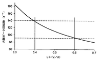
- FIG. 4 is a graph showing the relationship between L + (V / A) and the resonance peak rotational speed in the R32 refrigerant.
- the horizontal axis represents L + (V / A)
- the vertical axis represents the resonance peak rotational speed.
- the resonance peak rotational speed is 140 (s ⁇ 1 ) or more at which the sliding portion of the compression mechanism portion 11 deteriorates reliability due to wear. It becomes.
- the rotational speed at which the suction supercharging effect is obtained becomes low. Therefore, in this low rotational speed range, the suction supercharging effect with supercharging loss is used. It is more effective to improve the capacity by increasing the rotational speed without using the suction supercharging effect.
- the rotary compressor 4 in which the roller and the blade are separated as an example of the compressor has been described as an example.
- other types of compressors for example, a swing in which the roller and the blade are integrally formed, are described.
- the present invention can also be applied to a type compressor.
- the single-cylinder rotary compressor 4 having one cylinder 16 has been described as an example, but the present invention is also applied to a multi-cylinder rotary compressor having two or more cylinders. can do.
- the rotary compressor 4 that takes in the refrigerant into the compression mechanism portion via the accumulator 3 and discharges the refrigerant compressed by the compression mechanism portion through the sealed case 9 has been described as an example.
- the refrigerant is sucked into the sealed case 9 from the evaporator 7, the refrigerant in the sealed case 9 is sucked into the compression mechanism portion from the suction pipe, and the refrigerant compressed by the compression mechanism portion is not passed through the sealed case 9.
- the present invention can also be applied to a compressor that discharges.
Landscapes
- Engineering & Computer Science (AREA)
- Mechanical Engineering (AREA)
- General Engineering & Computer Science (AREA)
- Physics & Mathematics (AREA)
- Thermal Sciences (AREA)
- Applications Or Details Of Rotary Compressors (AREA)
- Compressor (AREA)
Abstract
圧縮機構部へのガス冷媒の吸込過給効果を利用した場合の圧縮機の性能を確実に向上させることができる圧縮機及び冷凍サイクル装置を提供する。 圧縮機構部と、この圧縮機構部を駆動する電動機部と、圧縮機構部の吸込口に連通される吸入管とを有し、R32冷媒或いはR32冷媒を70重量%以上含む混合冷媒を圧縮する圧縮機において、前記圧縮機構部の排除容積を単位をm3としてV、前記吸入管の断面積を単位をm2としてA、前記吸入管の長さを単位をmとしてLとしたとき、 2≦L/(V/A)≦3の関係式が成り立つようにした。
Description
本発明の実施形態は、圧縮機及び冷凍サイクル装置に関する。
従来、ガス冷媒を圧縮する圧縮機においては、吸込過給効果を利用するものが知られている。即ち、ガス冷媒が圧縮機構部に吸い込まれる際に発生するガス冷媒の脈動による圧力波の共振作用により圧縮機構部に吸い込まれるガス冷媒の量が多くなる吸込過給効果を利用して圧縮機の能力を増大するものである。この吸込過給効果を圧縮機の最大回転数のときに得られるようにすることにより、圧縮機の最大能力を増大でき、最小能力から最大能力までの能力可変幅を大きくすることができる。
この吸込過給効果が得られる圧縮機の共振ピーク回転数f(s-1)は、下記特許文献1に記載されているように、f=(2m-1)C/4{L+(V/A)}の式から求められる。但し、mは、1、2、3、…、の関数、Cは、ガス冷媒を伝わる音の速さ(m/s)、Lは、ガス冷媒が流れる吸入管の長さ(m)、Vは、圧縮機構部の排除容積(m3)、Aは、吸入管の断面積(m2)である。
このため、伝わる音の速さCが大きくなるガス冷媒を使用する場合には、従来の冷媒を使用する場合と同一の構成では吸込過給効果が得られる共振ピーク回転数fが大きくなり、圧縮機の許容回転数の範囲より高回転側にシフトすることがある。そこで、伝わる音の速さCが大きくなるガス冷媒を使用する場合において、共振ピーク回転数fを圧縮機の許容回転数の範囲内に保つためには、L+(V/A)を大きくする必要がある。
しかしながら、吸込過給効果を利用すると能力は増大できるが、仕事量も増大し、吸込過給効果を利用しない場合よりも成績係数(Coefficient Of Performance 以下COPという。)が低下することがある。
本発明の実施形態の目的は、圧縮機構部へのガス冷媒の吸込過給効果を利用する場合の圧縮機のCOPの低下を防止することができる圧縮機及び冷凍サイスル装置を得るにある。
実施形態の回転式圧縮機は、圧縮機構部と、この圧縮機構部を駆動する電動機部と、圧縮機構部の吸込口に連通される吸入管とを有し、R32冷媒或いはR32冷媒を70重量%以上含む混合冷媒を圧縮する圧縮機において、
前記圧縮機構部の排除容積を単位をm3としてV、前記吸入管の断面積を単位をm2としてA、前記吸入管の長さを単位をmとしてL、としたとき、
2≦L/(V/A)≦3の関係式が成り立つことを特徴とする。
前記圧縮機構部の排除容積を単位をm3としてV、前記吸入管の断面積を単位をm2としてA、前記吸入管の長さを単位をmとしてL、としたとき、
2≦L/(V/A)≦3の関係式が成り立つことを特徴とする。
これによれば、圧縮機構部へのガス冷媒の吸込過給効果を利用する場合の圧縮機のCOPの低下を防止することができる圧縮機及び冷凍サイスル装置を提供できる。
以下、実施形態を図面に基づいて説明する。
以下、一実施形態を図面に基づいて説明する。図1は冷凍サイクル装置1の全体構成を示しており、この冷凍サイクル装置1は、圧縮機本体2と、この圧縮機本体2とは別体に配置されたアキュムレータ3とを有している。また、圧縮機本体2内に収容されたガス冷媒を圧縮する回転式圧縮機4と、圧縮機本体2に接続されて圧縮機本体2から吐出された高圧・高温のガス冷媒を凝縮して液冷媒にする凝縮器5と、凝縮器5に接続されて液冷媒を減圧する膨張装置6と、膨張装置6とアキュムレータ3との間に接続されて膨張した液冷媒を蒸発させる蒸発器7とを有している。アキュムレータ3はその上部に蒸発器7で蒸発したガス冷媒が導入される導入口3aを有し、アキュムレータ3内では導入口3aから導入されたガス冷媒に含まれる液冷媒が分離される。アキュムレータ3と圧縮機本体2とは、ガス冷媒のみが流れる吸入管8により接続されている。
吸入管8は、アキュムレータ3の底部を貫通して設けられ、一端がアキュムレータ3内部の上方に開口し、他端が圧縮機本体2に設けられた後述する圧縮機構部の吸込口に連通されている。
この冷凍サイクル装置1では、ハイドロフルオロカーボン(HFC)からなるR32冷媒或いはR32冷媒を70重量%以上含む混合冷媒が使用され、回転式圧縮機4でそのガス冷媒が圧縮されるようになっている。
圧縮機本体2は、円筒状に形成された密閉ケース9を有し、この密閉ケース9内に、電動機部10とこの電動機部10により駆動されてガス冷媒を圧縮する圧縮機構部11とが収容されている。これら電動機部10と圧縮機構部11とは、電動機部10が上方に配置されて圧縮機構部11が下方に配置され、電動機部10と圧縮機構部11とは上下方向に延出して軸心回りに回転可能な回転軸12により連結されている。密閉ケース9内の底部には潤滑油13が貯留されている。
電動機部10は、回転軸12に固定された回転子14と、密閉ケース9の内側に固定されて回転子14を囲む位置に配置された固定子15とを有している。回転子14には永久磁石(図示せず)が設けられ、固定子15にはコイル(図示せず)が巻かれている。この電動機部10は、コイルへの通電により回転子14と回転軸12とが回転軸12の軸心回りに回転するようになっている。
圧縮機構部11は、密閉ケース9の内側部に固定されて、上下方向の両端が開口されたシリンダ16を有している。このシリンダ16には、シリンダ16の上端側を閉塞する閉塞部材として機能する主軸受17と、シリンダ16の下端側を閉塞する閉塞部材として機能する副軸受18とが固定されている。シリンダ16の両端面が主軸受17と副軸受18とで閉塞されることにより、シリンダ16内にシリンダ室19が形成されている。
シリンダ室19には回転軸12が挿通され、回転軸12は主軸受17と副軸受18とにより軸心回りに回転可能に軸支されている。回転軸12におけるシリンダ室19内に位置する部分には偏心部20が形成され、この偏心部20にローラ21が嵌合されている。ローラ21は、回転軸12が軸心回りに回転することに伴いシリンダ室19内で偏心回転するようになっている。
また、シリンダ16にはブレード溝(図示せず)が形成され、このブレード溝には板形状に形成されたブレード(図示せず)が往復移動可能に収容されている。ブレード溝の奥部にはスプリング(図示せず)が収容され、このスプリングによりブレードがローラ21側に向けて付勢され、ブレードの先端部がローラ21の外周面に当接されている。そして、ブレードの先端部がローラ21の外周面に当接することにより、シリンダ室19は、ガス冷媒を吸い込む吸込室22と、吸い込んだガス冷媒を圧縮する圧縮室(図示せず)とに二分されている。アキュムレータ3から吸込室22へのガス冷媒の吸い込みは、吸入管8と、シリンダ16に形成されて吸入管8の端部が接続される吸込口23とを経由して行われるようになっている。
主軸受17には、圧縮室で圧縮されたガス冷媒が吐出される吐出孔24が形成され、さらに、吐出孔24を開閉する吐出弁25が取付けられている。また、主軸受17には、吐出孔24と吐出弁25とを覆う吐出マフラ26が取付けられている。吐出マフラ26には、吐出孔24から吐出マフラ26内に吐出されたガス冷媒を密閉ケース9内に流出させる流出孔27が形成されている。
この回転式圧縮機4においては、圧縮機構部11の排除容積をV[m3]、吸入管8の断面積をA[m2]、吸入管8の長さをL[m]としたとき、V、A、Lは、2≦L/(V/A)≦3の関係式が成り立つように設定されている。さらに、V、A、Lは、0.4≦L+(V/A)≦0.6の関係式が成り立つように設定されている。
このような構成において、この回転式圧縮機4においては、電動機部10に通電されることにより回転軸12が回転子14と共に回転軸12の軸心回りに回転し、この回転により圧縮機構部11が駆動され、シリンダ室19内でガス冷媒が圧縮される。
圧縮されたガス冷媒の圧力が設定圧に達すると、吐出弁25が開弁され、ガス冷媒が吐出孔24から吐出マフラ26内に吐出される。吐出マフラ26内に吐出されたガス冷媒は、流出孔27から密閉ケース9内に流出する。
密閉ケース9内に流出したガス冷媒は、凝縮器5、膨張装置6、蒸発器7の順に流れて回転式圧縮機4に戻り、凝縮器5での放熱及び蒸発器7での吸熱が行われることにより冷凍サイクルが実行される。
ここで、回転式圧縮機4において、吸込過給効果が得られる共振ピーク回転数f(s-1)は、前述したように、f=(2m-1)C/4{L+(V/A)}の式から求められる。但し、mは、1、2、3、…、の関数、Cは、ガス冷媒を伝わる音の速さ(m/s)である。
ガス冷媒を伝わる音の速さCは、従来広く使用されているハイドロフルオロカーボン(HFC)からなるR410A冷媒に対し、R32冷媒或いはR32冷媒を70重量%以上含む混合冷媒では、1.3倍程度速くなる。
このため、冷媒として、R32冷媒或いはR32冷媒を70重量%以上含む混合冷媒を使用し、吸込過給を行う場合には、ガス冷媒を伝わる音の速さCが大きくなることに伴って、L+(V/A)を大きくする必要がある。
L+(V/A)を大きくする場合には、吸入管8の長さLを大きくする、吸入管8の断面積Aを小さくする等の方法があるが、LとV/Aとの比を変えることにより、COPが変化することが判明した。LとV/Aとの比を変えることによりCOPがどのように変化するかについて、図2、図3のグラフを用いて説明する。
図2は、圧縮機構部の排除容積がV、吸入管の断面積がA、吸入管の長さがLであり、使用するガス冷媒を流れる音の速さが異なる場合に吸込過給効果が得られるようにL+(V/A)を変えた場合において、吸込過給効果が得られる回転数で運転した場合のLとV/Aとの比に応じたCOPの変化を示すグラフである。
図2のグラフは、横軸にLとV/Aとの比をとり、縦軸にCOP比をとっている。COP比とは、R32冷媒を使用し、吸込過給効果が得られる共振ピーク回転数fが、R410A冷媒を使用したときと同じになるようにL+(V/A)を大きくした場合の、共振ピーク回転数fでのCOPの、吸込過給効果を利用しないで運転した場合のCOPに対する比である(吸込過給効果を利用しないで運転した場合のCOPを1としている)。なお、吸込過給効果を利用した場合と、吸込過給効果を利用しないで運転した場合の能力は同一になるようにしている。
この図2のグラフから、LとV/Aとの比を、2≦L/(V/A)とすることにより、吸込過給効果を利用した場合には吸込過給効果を利用しない場合に比べてCOP比が高くなることが分かる。一方、L/(V/A)<2の範囲では、吸込過給効果を利用した場合には吸込過給効果を利用しない場合に比べてCOP比が低くなることが分かる。
これは、L/(V/A)<2の範囲は、吸入管8内を流れるガス冷媒の流速に相当するV/Aの割合が大きくなることを意味し、ガス冷媒が吸入管8内を流れる際の圧力損失が急増するためである。一方、ガス冷媒の流速に相当するV/Aの増大を抑えるとともに、吸入管8の長さLを長くし、2≦L/(V/A)とすることにより、吸込過給効果による能力増大効果が、ガス冷媒が吸入管8内を流れる際の圧力損失を上回るためである。
図3は、圧縮機構部の排除容積がV、吸入管の断面積がA、吸入管の長さがLであり、使用するガス冷媒を流れる音の速さが異なる場合に吸込過給効果が得られるようにL+(V/A)を変えた場合において、吸込過給が得られない回転数で運転した場合のLとV/Aとの比に応じたCOPの変化を説明するグラフである。
図3のグラフは、横軸にLとV/Aとの比をとり、縦軸にCOP比をとっている。COP比とは、R32冷媒を使用し、吸込過給効果が得られる共振ピーク回転数fが、R410A冷媒を使用したときと同じになるようにL+(V/A)を大きくした場合の、共振ピーク回転数fより低い回転数(中間能力時の回転数)でのCOPの、吸込過給効果を利用しないで運転した場合のCOPに対する比である(吸込過給効果を利用しないで運転した場合のCOPを1としている)。
この図3のグラフから、吸込過給効果が得られる共振ピーク回転数fが、R410A冷媒を使用したときと同じになるようにL+(V/A)を大きくしたものは、吸込過給効果を利用しない回転数で運転した場合には、3<L/(V/A)の範囲ではCOP比が低くなることが分かる。
これは、3<L/(V/A)の範囲では、吸入管8内を流れるガス冷媒の流速に相当するV/Aが小さい上、吸入管8の長さLが長くなるため、ガス冷媒が吸入管8内を通過するのに要する時間が長くなり、ガス冷媒が吸入管8内を流れている間に周囲からの熱により暖められ、圧縮前のガス冷媒が暖められることによって能力低下が生ずるためである。一方、L/(V/A)≦3とすることにより、ガス冷媒が吸入管8内を通過するのに要する時間が短くなり、ガス冷媒が吸入管8内を流れている間に周囲からの熱により暖められことが少なくなり、圧縮前のガス冷媒が暖められることによる能力低下が抑えられるためである。
以上の図2と図3とから、R32冷媒或いはR32冷媒を70重量%以上含む混合冷媒を圧縮する圧縮機においては、LとV/Aとの比を、2≦L/(V/A)≦3の関係式が成り立つように設定することにより、吸込過給効果を利用して回転式圧縮機4の能力の増大を図るとともに、COPの低下を防止することができ、しかも、吸込過給効果を利用しない回転数で運転した場合においても能力の低下を防止することができることが判明した。
図4は、R32冷媒における、L+(V/A)と共振ピーク回転数との関係を示すグラフである。このグラフは、横軸にL+(V/A)をとり、縦軸に共振ピーク回転数をとっている。
この図4のグラフから、L+(V/A)<0.4の範囲においては、共振ピーク回転数が、圧縮機構部11の摺動部が摩耗により信頼性を損なう140(s-1)以上となる。また、0.6<L+(V/A)の範囲では、吸込過給効果が得られる回転数が低くなるため、この低い回転数の範囲では、過給損失を伴う吸込過給効果を利用するよりも、吸込過給効果を利用せず回転数を増大させることによる能力向上を図ることが有効である。
したがって、この図4から、R32冷媒或いはR32冷媒を70重量%以上含む混合冷媒を圧縮する圧縮機において、0.4≦L+(V/A)≦0.6とすることにより、吸込過給効果を利用して回転式圧縮機4の能力を確実に向上できることが判明した。
なお、本実施形態においては、圧縮機としてローラとブレードが別体の回転式圧縮機4を例に挙げて説明したが、他の形式の圧縮機、例えば、ローラとブレードが一体形成されたスイング式圧縮機においても本発明を適用することができる。
さらに、本実施形態では、1つのシリンダ16を有する単気筒の回転式圧縮機4を例に挙げて説明したが、2つ以上のシリンダを有する多気筒の回転式圧縮機においても本発明を適用することができる。
また、本実施形態では、アキュムレータ3を介して冷媒を圧縮機構部に吸込み、圧縮機構部で圧縮した冷媒を、密閉ケース9内を介して吐出する回転圧縮機4を例に挙げて説明したが、これに限らず、蒸発器7から冷媒を密閉ケース9内に吸込み、密閉ケース9内の冷媒を吸込管から圧縮機構部に吸込み、圧縮機構部で圧縮した冷媒を密閉ケース9を通さずに吐出する圧縮機にも適用することができる。
以上、本発明の実施形態を説明したが、この実施形態は、例として提示したものであり、発明の範囲を限定することは意図していない。この実施形態は、その他の様々な形態で実施されることが可能であり、発明の要旨を逸脱しない範囲で、種々の省略、置き換え、変更を行うことができる。この実施形態やその変形は、発明の範囲や要旨に含まれると同様に、特許請求の範囲に記載された発明とその均等の範囲に含まれるものである。
1…冷凍サイクル装置
3…アキュムレータ
3a…導入口
4…回転式圧縮機(圧縮機)
5…凝縮器
6…膨張装置
7…蒸発器
10…電動機部
11…圧縮機構部
22…吸込口
3…アキュムレータ
3a…導入口
4…回転式圧縮機(圧縮機)
5…凝縮器
6…膨張装置
7…蒸発器
10…電動機部
11…圧縮機構部
22…吸込口
Claims (3)
- 圧縮機構部と、この圧縮機構部を駆動する電動機部と、前記圧縮機構部の吸込口に連通される吸入管とを有し、R32冷媒或いはR32冷媒を70重量%以上含む混合冷媒を圧縮する圧縮機において、
前記圧縮機構部の排除容積を単位をm3としてV、前記吸入管の断面積を単位をm2としてA、前記吸入管の長さを単位をmとしてLとしたとき、
2≦L/(V/A)≦3の関係式が成り立つことを特徴とする圧縮機。 - 0.4≦L+(V/A)≦0.6の関係式が成り立つことを特徴とする請求項1記載の圧縮機。
- 請求項1又は2に記載の圧縮機と、前記圧縮機に接続される凝縮器と、前記凝縮器に接続される膨張装置と、前記膨張装置に接続される蒸発器とを備えることを特徴とする冷凍サイクル装置。
Priority Applications (1)
| Application Number | Priority Date | Filing Date | Title |
|---|---|---|---|
| CN201680003779.XA CN107002655A (zh) | 2015-02-24 | 2016-02-12 | 压缩机和冷冻循环装置 |
Applications Claiming Priority (2)
| Application Number | Priority Date | Filing Date | Title |
|---|---|---|---|
| JP2015034294A JP6351522B2 (ja) | 2015-02-24 | 2015-02-24 | 圧縮機及び冷凍サイクル装置 |
| JP2015-034294 | 2015-02-24 |
Publications (1)
| Publication Number | Publication Date |
|---|---|
| WO2016136504A1 true WO2016136504A1 (ja) | 2016-09-01 |
Family
ID=56788403
Family Applications (1)
| Application Number | Title | Priority Date | Filing Date |
|---|---|---|---|
| PCT/JP2016/054160 Ceased WO2016136504A1 (ja) | 2015-02-24 | 2016-02-12 | 圧縮機及び冷凍サイクル装置 |
Country Status (3)
| Country | Link |
|---|---|
| JP (1) | JP6351522B2 (ja) |
| CN (1) | CN107002655A (ja) |
| WO (1) | WO2016136504A1 (ja) |
Families Citing this family (2)
| Publication number | Priority date | Publication date | Assignee | Title |
|---|---|---|---|---|
| CN109945559B (zh) | 2019-03-13 | 2020-11-13 | 珠海格力电器股份有限公司 | 气液分离器、压缩机组件及空调器 |
| CN110567204A (zh) * | 2019-09-30 | 2019-12-13 | 珠海凌达压缩机有限公司 | 一种分液器、压缩机及空调系统 |
Citations (4)
| Publication number | Priority date | Publication date | Assignee | Title |
|---|---|---|---|---|
| JPH0370881A (ja) * | 1989-08-10 | 1991-03-26 | Toshiba Corp | 圧縮機 |
| JPH0642484A (ja) * | 1992-07-24 | 1994-02-15 | Hitachi Ltd | 2シリンダ形ロータリ圧縮機 |
| US5873261A (en) * | 1995-09-25 | 1999-02-23 | Lg Electronics Inc. | Accumulator for rotary compressor |
| JP2001304116A (ja) * | 2000-04-19 | 2001-10-31 | Daikin Ind Ltd | 冷凍装置 |
Family Cites Families (2)
| Publication number | Priority date | Publication date | Assignee | Title |
|---|---|---|---|---|
| JPS63106376A (ja) * | 1986-10-24 | 1988-05-11 | Hitachi Ltd | 過給式圧縮機 |
| WO2012169339A1 (ja) * | 2011-06-08 | 2012-12-13 | 東芝キヤリア株式会社 | 密閉型圧縮機及び冷凍サイクル装置 |
-
2015
- 2015-02-24 JP JP2015034294A patent/JP6351522B2/ja active Active
-
2016
- 2016-02-12 WO PCT/JP2016/054160 patent/WO2016136504A1/ja not_active Ceased
- 2016-02-12 CN CN201680003779.XA patent/CN107002655A/zh active Pending
Patent Citations (4)
| Publication number | Priority date | Publication date | Assignee | Title |
|---|---|---|---|---|
| JPH0370881A (ja) * | 1989-08-10 | 1991-03-26 | Toshiba Corp | 圧縮機 |
| JPH0642484A (ja) * | 1992-07-24 | 1994-02-15 | Hitachi Ltd | 2シリンダ形ロータリ圧縮機 |
| US5873261A (en) * | 1995-09-25 | 1999-02-23 | Lg Electronics Inc. | Accumulator for rotary compressor |
| JP2001304116A (ja) * | 2000-04-19 | 2001-10-31 | Daikin Ind Ltd | 冷凍装置 |
Also Published As
| Publication number | Publication date |
|---|---|
| CN107002655A (zh) | 2017-08-01 |
| JP6351522B2 (ja) | 2018-07-04 |
| JP2016156314A (ja) | 2016-09-01 |
Similar Documents
| Publication | Publication Date | Title |
|---|---|---|
| CN106715913B (zh) | 旋转式压缩机及冷冻循环装置 | |
| WO2005103496A1 (ja) | 回転式流体機械 | |
| CN106574620B (zh) | 旋转式压缩机以及冷冻循环装置 | |
| JP6071190B2 (ja) | 多気筒回転式圧縮機及び冷凍サイクル装置 | |
| KR101324373B1 (ko) | 다기통 로터리식 압축기와 냉동 사이클 장치 | |
| JP6351522B2 (ja) | 圧縮機及び冷凍サイクル装置 | |
| JP2012215158A (ja) | 圧縮機及びこの圧縮機を搭載した冷凍サイクル装置 | |
| JP2016037865A (ja) | 密閉型圧縮機および冷凍サイクル装置 | |
| JP6262101B2 (ja) | 回転式圧縮機及び冷凍サイクル装置 | |
| JP2011032958A (ja) | 回転式流体機械 | |
| JP6404142B2 (ja) | 圧縮機及び冷凍サイクル装置 | |
| JP6256643B2 (ja) | 揺動ピストン式圧縮機 | |
| EP3636929B1 (en) | Rotary compressor | |
| JP6019669B2 (ja) | 回転式圧縮機 | |
| JP6007030B2 (ja) | 回転式圧縮機と冷凍サイクル装置 | |
| JP2000297745A (ja) | 圧縮機 | |
| KR102163622B1 (ko) | 마찰 손실을 저감한 로터리 압축기 | |
| JP6321400B2 (ja) | 密閉型圧縮機 | |
| JP5929189B2 (ja) | 揺動ピストン式圧縮機 | |
| EP4729784A1 (en) | Rotary compressor and refrigeration apparatus | |
| KR20130080289A (ko) | 2단 로터리 압축기 | |
| JP2017008878A (ja) | 圧縮機 | |
| WO2018189827A1 (ja) | 密閉型圧縮機及び冷凍サイクル装置 | |
| JP2017008845A (ja) | 気体圧縮機 | |
| JP2018009497A (ja) | 回転式圧縮機 |
Legal Events
| Date | Code | Title | Description |
|---|---|---|---|
| 121 | Ep: the epo has been informed by wipo that ep was designated in this application |
Ref document number: 16755251 Country of ref document: EP Kind code of ref document: A1 |
|
| NENP | Non-entry into the national phase |
Ref country code: DE |
|
| 122 | Ep: pct application non-entry in european phase |
Ref document number: 16755251 Country of ref document: EP Kind code of ref document: A1 |