WO2016136055A1 - 摩耗検査装置、摩耗検査方法及びプログラム - Google Patents
摩耗検査装置、摩耗検査方法及びプログラム Download PDFInfo
- Publication number
- WO2016136055A1 WO2016136055A1 PCT/JP2015/082689 JP2015082689W WO2016136055A1 WO 2016136055 A1 WO2016136055 A1 WO 2016136055A1 JP 2015082689 W JP2015082689 W JP 2015082689W WO 2016136055 A1 WO2016136055 A1 WO 2016136055A1
- Authority
- WO
- WIPO (PCT)
- Prior art keywords
- image
- boundary
- guide wheel
- imaging unit
- unit
- Prior art date
- Legal status (The legal status is an assumption and is not a legal conclusion. Google has not performed a legal analysis and makes no representation as to the accuracy of the status listed.)
- Ceased
Links
Images




Classifications
-
- G—PHYSICS
- G01—MEASURING; TESTING
- G01B—MEASURING LENGTH, THICKNESS OR SIMILAR LINEAR DIMENSIONS; MEASURING ANGLES; MEASURING AREAS; MEASURING IRREGULARITIES OF SURFACES OR CONTOURS
- G01B11/00—Measuring arrangements characterised by the use of optical techniques
- G01B11/02—Measuring arrangements characterised by the use of optical techniques for measuring length, width or thickness
- G01B11/026—Measuring arrangements characterised by the use of optical techniques for measuring length, width or thickness by measuring distance between sensor and object
-
- B—PERFORMING OPERATIONS; TRANSPORTING
- B61—RAILWAYS
- B61B—RAILWAY SYSTEMS; EQUIPMENT THEREFOR NOT OTHERWISE PROVIDED FOR
- B61B13/00—Other railway systems
-
- B—PERFORMING OPERATIONS; TRANSPORTING
- B61—RAILWAYS
- B61F—RAIL VEHICLE SUSPENSIONS, e.g. UNDERFRAMES, BOGIES OR ARRANGEMENTS OF WHEEL AXLES; RAIL VEHICLES FOR USE ON TRACKS OF DIFFERENT WIDTH; PREVENTING DERAILING OF RAIL VEHICLES; WHEEL GUARDS, OBSTRUCTION REMOVERS OR THE LIKE FOR RAIL VEHICLES
- B61F9/00—Rail vehicles characterised by means for preventing derailing, e.g. by use of guide wheels
-
- B—PERFORMING OPERATIONS; TRANSPORTING
- B61—RAILWAYS
- B61K—AUXILIARY EQUIPMENT SPECIALLY ADAPTED FOR RAILWAYS, NOT OTHERWISE PROVIDED FOR
- B61K9/00—Railway vehicle profile gauges; Detecting or indicating overheating of components; Apparatus on locomotives or cars to indicate bad track sections; General design of track recording vehicles
- B61K9/12—Measuring or surveying wheel-rims
-
- B—PERFORMING OPERATIONS; TRANSPORTING
- B61—RAILWAYS
- B61L—GUIDING RAILWAY TRAFFIC; ENSURING THE SAFETY OF RAILWAY TRAFFIC
- B61L23/00—Control, warning or like safety means along the route or between vehicles or trains
-
- B—PERFORMING OPERATIONS; TRANSPORTING
- B61—RAILWAYS
- B61L—GUIDING RAILWAY TRAFFIC; ENSURING THE SAFETY OF RAILWAY TRAFFIC
- B61L27/00—Central railway traffic control systems; Trackside control; Communication systems specially adapted therefor
- B61L27/40—Handling position reports or trackside vehicle data
-
- B—PERFORMING OPERATIONS; TRANSPORTING
- B61—RAILWAYS
- B61L—GUIDING RAILWAY TRAFFIC; ENSURING THE SAFETY OF RAILWAY TRAFFIC
- B61L27/00—Central railway traffic control systems; Trackside control; Communication systems specially adapted therefor
- B61L27/50—Trackside diagnosis or maintenance, e.g. software upgrades
- B61L27/57—Trackside diagnosis or maintenance, e.g. software upgrades for vehicles or trains, e.g. trackside supervision of train conditions
-
- G—PHYSICS
- G01—MEASURING; TESTING
- G01B—MEASURING LENGTH, THICKNESS OR SIMILAR LINEAR DIMENSIONS; MEASURING ANGLES; MEASURING AREAS; MEASURING IRREGULARITIES OF SURFACES OR CONTOURS
- G01B11/00—Measuring arrangements characterised by the use of optical techniques
- G01B11/02—Measuring arrangements characterised by the use of optical techniques for measuring length, width or thickness
-
- G—PHYSICS
- G01—MEASURING; TESTING
- G01B—MEASURING LENGTH, THICKNESS OR SIMILAR LINEAR DIMENSIONS; MEASURING ANGLES; MEASURING AREAS; MEASURING IRREGULARITIES OF SURFACES OR CONTOURS
- G01B11/00—Measuring arrangements characterised by the use of optical techniques
- G01B11/02—Measuring arrangements characterised by the use of optical techniques for measuring length, width or thickness
- G01B11/04—Measuring arrangements characterised by the use of optical techniques for measuring length, width or thickness specially adapted for measuring length or width of objects while moving
-
- G—PHYSICS
- G01—MEASURING; TESTING
- G01B—MEASURING LENGTH, THICKNESS OR SIMILAR LINEAR DIMENSIONS; MEASURING ANGLES; MEASURING AREAS; MEASURING IRREGULARITIES OF SURFACES OR CONTOURS
- G01B11/00—Measuring arrangements characterised by the use of optical techniques
- G01B11/08—Measuring arrangements characterised by the use of optical techniques for measuring diameters
-
- G—PHYSICS
- G01—MEASURING; TESTING
- G01B—MEASURING LENGTH, THICKNESS OR SIMILAR LINEAR DIMENSIONS; MEASURING ANGLES; MEASURING AREAS; MEASURING IRREGULARITIES OF SURFACES OR CONTOURS
- G01B11/00—Measuring arrangements characterised by the use of optical techniques
- G01B11/24—Measuring arrangements characterised by the use of optical techniques for measuring contours or curvatures
-
- G—PHYSICS
- G01—MEASURING; TESTING
- G01M—TESTING STATIC OR DYNAMIC BALANCE OF MACHINES OR STRUCTURES; TESTING OF STRUCTURES OR APPARATUS, NOT OTHERWISE PROVIDED FOR
- G01M17/00—Testing of vehicles
- G01M17/007—Wheeled or endless-tracked vehicles
- G01M17/02—Tyres
- G01M17/027—Tyres using light, e.g. infrared, ultraviolet or holographic techniques
-
- G—PHYSICS
- G01—MEASURING; TESTING
- G01M—TESTING STATIC OR DYNAMIC BALANCE OF MACHINES OR STRUCTURES; TESTING OF STRUCTURES OR APPARATUS, NOT OTHERWISE PROVIDED FOR
- G01M17/00—Testing of vehicles
- G01M17/08—Railway vehicles
- G01M17/10—Suspensions, axles or wheels
Definitions
- the present invention relates to a wear inspection apparatus, a wear inspection method, and a program.
- This application claims priority based on Japanese Patent Application No. 2015-038661 filed in Japan on February 27, 2015, the contents of which are incorporated herein by reference.
- the automatic measurement system for sliding plate wear described in Patent Document 1 uses a detection signal for detecting a pantograph for a vehicle moving in a garage. The amount of wear on the sliding plate is automatically measured without contact. In Patent Document 1, this contributes to the safety and labor saving of the pantograph maintainer.
- ⁇ It is desirable to be able to detect wear conditions efficiently not only for pantographs but also for other parts.
- the present invention provides a wear inspection apparatus, a wear inspection method, and a program that can efficiently detect the wear state of vehicle parts.
- the wear inspection device is provided on the side of the track on which the vehicle having the guide wheels provided on the side travels, and images the inside of the track via the telecentric lens.
- a first imaging unit; a second imaging unit provided in a vehicle traveling direction with respect to the first imaging unit at a side of the track; and imaging the inside of the track via a telecentric lens; and the first imaging An image of the boundary of the guide wheels imaged by the unit, the image of the boundary on the first direction side (that is, one side in the vehicle traveling direction) along the vehicle traveling direction, and the imaging of the image by the first imaging unit
- An image acquisition unit that acquires an image of the boundary of the guide wheel captured by the second imaging unit at the same time and an image of the boundary on the opposite side of the first direction (that is, the other side in the vehicle traveling direction); , Acquired by the image acquisition unit Was based on the position of the boundary represented by the image, and a guide wheel detection unit for detecting the wear status of said guide wheels.
- a third imaging unit that is provided on the side of a track on which a vehicle with guide wheels provided on the side travels and images the inside of the track via a telecentric lens, and the third imaging on the side of the track.
- a fourth imaging unit that is provided in a vehicle traveling direction with respect to the unit and that images the inside of the track via a telecentric lens, and is in contact with the guide wheel at a side of the track.
- the first imaging unit and the second imaging unit are both positions where the rotation mechanism captures an image of the boundary of the guide wheel before the rotation mechanism rotates the guide wheel.
- the third imaging unit and the fourth imaging unit are both provided at positions where the rotation mechanism captures an image of a boundary in the guide wheel after the rotation mechanism rotates the guide wheel.
- an image of the boundary of the guide wheel captured by the fourth imaging unit and the boundary image on the opposite side of the first direction is acquired, and the detection unit for the guide wheel captures the first imaging
- the wear state of the guide wheel is detected based on the position of the boundary indicated by the image captured by the image capturing unit and the image captured by the second image capturing unit, and further the image captured by the third image capturing unit, You may make it detect the wear condition of the said guide wheel based on the position of the boundary shown by each image which 4 image pick-up parts imaged.
- a distance measuring unit that is provided below the track and measures a distance to an object located above and having an inclination in a vehicle traveling direction with respect to a vertical direction; and the distance measuring unit measured by the distance measuring unit; You may make it further provide the detection part for tires which detects the abrasion condition of the said tire for driving
- the wear inspection device is provided below the track of the traffic system in which the traveling tire is provided below the vehicle, and has an inclination in the vehicle traveling direction with respect to the vertical direction. Based on the distance between the distance measuring unit that measures the distance to the object located above and the distance between the distance measuring unit and the vehicle traveling tire measured by the distance measuring unit, the wear state of the traveling tire is determined. And a tire detection unit for detection.
- the wear inspection method is provided on a side of a track on which a vehicle having guide wheels provided on the side travels, and images the inside of the track via a telecentric lens.
- a wear inspection comprising: a first imaging unit; and a second imaging unit that is provided in a vehicle traveling direction with respect to the first imaging unit at a side of the track and images the inside of the track via a telecentric lens.
- a wear inspection method for an apparatus which is an image of a boundary of the guide wheels captured by the first imaging unit and is a boundary image on a first direction side along a vehicle traveling direction, and the first imaging unit
- An image of the boundary of the guide wheel captured by the second imaging unit at the same time as the image capturing and the boundary image on the opposite side of the first direction is acquired and acquired in the image acquisition step Of the boundary shown in the image Based on the location, for detecting the wear status of said guide wheels.
- the program is provided on a side of a track on which a vehicle having guide wheels provided on the side travels, and images the inside of the track via a telecentric lens.
- a wear inspection apparatus comprising: an imaging unit; and a second imaging unit that is provided in a vehicle traveling direction with respect to the first imaging unit at a side of the track and images the inside of the track via a telecentric lens.
- the image of the boundary of the guide wheel imaged by the second imaging unit at the same time and the image of the boundary on the opposite side of the first direction is acquired and shown by the image acquired in the image acquisition step Border Based on the position, which is a program for causing the detecting wear status of said guide wheels.
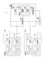
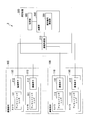
- FIG. 1 is a schematic block diagram showing a functional configuration of a wear inspection apparatus according to an embodiment of the present invention.
- the wear inspection apparatus 1 includes a camera 110, a laser sensor 200, and an arithmetic device 300.
- the camera 110 includes a telecentric lens 111 and an image sensor 112.
- the arithmetic device 300 includes an image acquisition unit 310, a distance information acquisition unit 320, a storage unit 380, and a calculation unit 390.
- the computing unit 390 includes a guide wheel branch wheel wear state detection unit (hereinafter referred to as a side wheel detection unit) 391 and a tire wear state detection unit (hereinafter referred to as a tire detection unit) 392.
- a guide wheel branch wheel wear state detection unit hereinafter referred to as a side wheel detection unit
- a tire wear state detection unit hereinafter referred to as a tire detection unit
- Two cameras 110 are paired to form an imaging unit pair 100.
- the number of imaging unit pairs 100 included in the wear inspection apparatus 1 may be one or more.
- the wear inspection apparatus 1 is an apparatus for inspecting the wear of guide wheels, the wear of branch wheels, and the wear of traveling tires provided in a vehicle of a traffic system.
- FIG. 2 is an external view showing an outline of the outer shape of the lower part of the vehicle as viewed from the front.
- traveling tires 921 are provided on the left and right sides of the vehicle main body 910 via shafts 922, and the traveling tires 921 are in contact with the road surface.
- Support bodies 930 are provided on the left and right sides of the vehicle main body 910, respectively.
- a guide wheel 941 is provided on the support 930 via a shaft 942.
- a branch ring 951 is provided on the support body 930 via a shaft 952.
- the vehicle 900 travels when the traveling tire 921 rotates about the shaft 922.
- the guide wheel 941 contacts the guide rail provided on the side of the track on which the vehicle 900 travels and restricts the traveling direction of the vehicle 900, thereby causing the vehicle 900 to travel along the track.
- the branching wheel 951 controls the traveling direction of the vehicle 900 at the branching point by restricting the traveling direction of the vehicle 900 in contact with the guide rail provided on the side of the track at the branching point of the track.
- the traveling tire 921 is worn by contact with the road surface.
- Both the guide wheel 941 and the branch wheel 951 are worn by contact with the guide rail.
- FIG. 2 shows an arrangement example of the camera 110 and the laser sensor 200.
- cameras 110-1 and 110-2 are provided on the side of the track so as to capture the inside of the track.
- the camera 110-1 is provided at a height at which the guide wheel 941 is imaged from the horizontal direction.
- the image captured by the camera 110-1 is used by the side wheel detection unit 391 to determine the wear state of the guide wheel 941.
- the camera 110-2 is provided at a height at which the branch wheel 951 is imaged from the horizontal direction.
- the image captured by the camera 110-2 is used by the side wheel detection unit 391 to determine the wear state of the branch wheel 951.
- the laser sensor 200 is installed with a hole in the road surface. As will be described later, the laser sensor 200 is installed in a direction having an inclination in the traveling direction of the vehicle 900 with respect to the vertical direction.
- the camera 110 is provided on the side of the track on which the vehicle 900 travels, and images the inside of the track.
- the camera 110-1 images the guide wheel 941 as described above.
- the camera 110-2 images the branch wheel 951 as described above.
- the track on which the camera 110 is provided may be a track on which the vehicle 900 travels during normal operation, or may be a track dedicated to inspection.
- the telecentric lens 111 collects light from the outside of the camera 110 at the position of the image sensor 112 and forms an image of the subject.
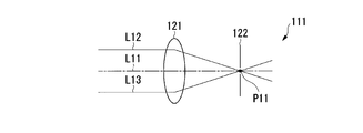
- FIG. 3 is an explanatory diagram showing an example of chief rays in the telecentric lens 111.
- the telecentric lens 111 includes a lens body 121 and a diaphragm 122.
- the diaphragm 122 is provided at the position of the focal point P11 of the lens main body 121, so that the principal ray is object-side telecentric parallel to the lens optical axis.
- the line L11 indicates the lens optical axis
- the lines L12 and L13 both indicate examples of chief rays.
- Both of the lines L12 and L13 indicating the principal ray are parallel to the line L11 indicating the lens optical axis on the object side (subject side).
- the camera 110 images the whole from the side of the guide wheel 941 and measures the size (diameter) of the guide wheel 941. It is done.
- a telecentric lens having a large aperture is necessary as the telecentric lens 111. If a telecentric lens having a large aperture is used, the equipment cost is high, and a large space may be required for installation of the camera 110. Therefore, in the wear inspection apparatus 1, the imaging unit pair 100 in which the two cameras 110 are paired captures the left and right boundaries of the guide wheel 941 at the same time. This point will be described with reference to FIG.
- FIG. 4 is an explanatory diagram showing an example of imaged portions of the guide wheel 941 and the branch wheel 951 by the camera 110.
- the cameras 110-1a and 110-1b image the guide wheel 941.
- the cameras 110-2a and 110-2b capture the branch wheel 951.
- Arrow A11 indicates the traveling direction of the vehicle 900.
- One of the cameras 110-1a and 110-1b corresponds to the example of the first imaging unit, and captures an image of the boundary of the guide wheel 941 in the first direction along the vehicle traveling direction. To do.
- the other of the cameras 110-1a and 110-1b corresponds to the example of the second imaging unit, and captures an image of the boundary of the guide wheel 941 on the side opposite to the first direction.
- the camera 110-1a captures an image of the front boundary of the guide wheel 941 in the vehicle traveling direction
- the camera 110-1b captures an image of the boundary behind the guide wheel 941 in the vehicle traveling direction.
- the camera 110-1a is provided away from the camera 110-1b in the vehicle traveling direction.
- the camera 110-1a and the camera 110-1b capture images at the same time.
- the imaging timing of the camera 110-1a and the imaging timing of the camera 110-1b do not have to be strictly the same, and may be almost the same.
- the distance D11 between the boundaries on both sides of the side wheel detection unit 391 can be calculated.
- the side wheel detection unit 391 detects an image of the boundary of the guide wheel 941 from the image captured by the camera 110-1a and the image captured by the camera 110-1b.
- the side wheel detection unit 391 is known about the positional relationship between the cameras 110-1a and 110-1b (particularly, the distance between the cameras 110-1a and 110-1b) and the magnification (enlargement / reduction ratio) of the image.
- the distance D11 is calculated based on the position of the detected boundary image in the image. Since the cameras 110-1a and 110-1b include the telecentric lens 111, the side wheel detection unit 391 needs to correct the distance according to the position in the depth direction of the guide wheel 941 viewed from the camera 110. Without it, the distance D11 can be calculated.
- Each of the cameras 110-2a and 110-2b is an image of the boundary of the branch wheel 951, which is an image of the boundary on the first direction side along the vehicle traveling direction, and an image of the boundary of the branch wheel 951. An image of the boundary between the direction side and the opposite side is taken. Specifically, the camera 110-2a captures an image of the front boundary of the branch wheel 951 in the vehicle traveling direction, and the camera 110-2b captures an image of the boundary of the branch wheel 951 at the rear of the vehicle traveling direction. The camera 110-2a is provided in the vehicle traveling direction with respect to the camera 110-2b.
- the distance D12 between the boundaries on both sides of the branch wheel 951 can be calculated.
- the side wheel detection unit 391 detects the image of the boundary of the branch wheel 951 from the image captured by the camera 110-2a and the image captured by the camera 110-2b.
- the side wheel detection unit 391 is known about the positional relationship between the cameras 110-2a and 110-2b (particularly, the distance between the cameras 110-2a and 110-2b) and the magnification (enlargement / reduction ratio) of the image.
- the distance D12 is calculated based on the position of the detected boundary image in the image. Since the cameras 110-1a and 110-1b include the telecentric lens 111, the side wheel detection unit 391 needs to correct the distance according to the position in the depth direction of the guide wheel 941 viewed from the camera 110. Without it, the distance D12 can be calculated.
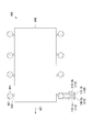
- FIG. 5 is an external view showing an outline of the outer shape of the vehicle 900 as viewed from above.
- the support body 930 is provided on each of the left and right sides of the vehicle main body 910, and the support body 930 is provided with the guide wheel 941 and the branch wheel 951.
- cameras 110-1a, 110-1b, 110-2a, and 110-2b are provided on the side of the track so as to image the inside of the track.
- the cameras 110-1a and 110-1b capture the guide wheel 941.
- the cameras 110-2a and 110-2b capture the branch wheel 951.
- An arrow A21 indicates the traveling direction of the vehicle 900.
- a plurality of guide wheels 941 and branch wheels 951 are provided on each side surface of the vehicle main body 910.
- the camera 110-1a, 110-1b may always take an image, and the border image of the guide wheel 941 may be taken every time the border of the guide wheel 941 is positioned in front of the camera 110 itself.
- the side wheel detection unit 391 can determine the wear state of the plurality of guide wheels 941.
- the cameras 110-2a and 110-2b may always take an image, and an image of the boundary may be taken every time the boundary of the branch wheel 951 is positioned in front of the camera 110 itself.
- the side wheel detection unit 391 can determine the wear state of the plurality of branch wheels 951.
- FIG. 5 shows an example in which the camera 110 is provided on only one side of the track, the camera 110 may be provided on the sides on both sides of the track.
- the image sensor 112 photoelectrically converts the light collected by the telecentric lens 111 to generate image data.
- the laser sensor 200 corresponds to an example of a distance measurement unit, and measures the distance to an object in the laser irradiation direction. In particular, when there is a traveling tire 921 in the laser irradiation direction, the laser sensor 200 measures the distance between the laser sensor 200 and the surface of the traveling tire 921. At that time, the laser sensor 200 irradiates laser light that spreads in the width direction of the traveling tire 921 and measures the distance to each part.
- FIG. 6 is an explanatory diagram showing an installation example of the laser sensor 200.
- a hole having a width D22 narrower than the width D21 of the traveling tire 921 is provided at a position on the road surface where the traveling tire 921 travels, and the laser sensor 200 is provided in the hole.
- the laser sensor 200 irradiates the traveling tire 921 with laser light having a width D24 and measures the distance from the laser sensor 200 to each part. Therefore, the laser sensor 200 measures the distance from the laser sensor 200 to each part linearly in the width direction of the traveling tire 921.
- the width D21 of the traveling tire 921 is about 300 millimeters (mm), while the hole width D22 is about 50 millimeters.
- the laser sensor 200 measures the distance to each part with respect to a width D24 of about 250 mm at the position of the traveling tire 921 where the irradiation distance of the laser beam is about 450 mm.
- the tire detection unit 392 calculates the depth of the groove provided on the surface of the traveling tire 921.
- the laser sensor 200 is provided below the track and is installed so as to measure the distance to the traveling tire 921 positioned above and having an inclination in the vehicle traveling direction with respect to the vertical direction. ing. As described above, the laser sensor 200 measures the distance to the traveling tire 921 positioned in a direction having an inclination in the vehicle traveling direction with respect to the vertical direction. As a result, the laser sensor 200 can perform measurement in a state where the traveling tire 921 is not in contact with the ground, and thus the traveling tire 921 is not crushed by weight. Thereby, the tire detection unit 392 can calculate the depth of the groove of the traveling tire 921 more accurately than when the traveling tire 921 is calculated with the weight collapsed.
- the arithmetic device 300 detects the wear state of the guide wheel 941 and the wear state of the branch wheel 951 based on the image captured by the camera 110. In addition, the arithmetic device 300 detects the wear state of the traveling tire 921 based on the distance detected by the laser sensor 200.
- the arithmetic device 300 is configured using, for example, a computer.
- the image acquisition unit 310 acquires an image captured by the camera 110.
- the image acquisition unit 310 is an image of the boundary of the guide wheel 941 captured by the two cameras 110 forming the imaging unit pair 100, and the boundary image on the first direction side along the vehicle traveling direction, and the first An image of a boundary between the one direction side and the opposite side is acquired.
- the image acquisition unit 310 is an image of the boundary of the branched wheel 951 captured by the two cameras 110 constituting the imaging unit pair 100, and the boundary image on the first direction side along the vehicle traveling direction, and the first An image of a boundary between the one direction side and the opposite side is acquired.
- the image acquisition unit 310 is configured as a communication circuit that communicates with each of the cameras 110 and receives image data.
- the distance information acquisition unit 320 acquires distance information indicating the result of distance measurement by the laser sensor 200.
- the distance information acquisition unit 320 is configured as a communication circuit that communicates with the laser sensor 200 and receives distance information, for example.
- storage part 380 is comprised using the memory
- the storage unit 380 stores the image data acquired by the image acquisition unit 310 and the distance information acquired by the distance information acquisition unit 320.
- the calculation unit 390 controls each unit of the calculation device 300 and performs various processes such as various calculations.
- the arithmetic unit 390 is configured by, for example, a CPU (Central Processing Unit) provided in the arithmetic device 300 reads out and executes a program from the storage unit 380.
- the side wheel detection unit 391 corresponds to an example of a guide wheel wear state detection unit (hereinafter referred to as a guide wheel detection unit), and the boundary of the guide wheel 941 indicated by the image acquired by the image acquisition unit 310. Based on the position, the wear state of the guide wheel 941 is detected.
- the side wheel detection unit 391 calculates the length between the boundaries based on the images of the boundaries on both sides of the guide wheel 941 captured by the two cameras 110 forming the imaging unit pair 100. The obtained length is compared with a threshold value to determine whether or not to output an alarm. The side wheel detection unit 391 detects the wear state of the branch wheel 951 as in the case of the guide wheel 941.
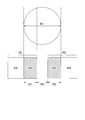
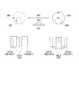
- FIG. 7 is an explanatory diagram illustrating an example of a correspondence relationship between an image captured by the camera 110 and the guide wheel 941.
- an image P21 is an image of the boundary of the guide wheel 941 taken by the camera 110 (for example, the camera 110-1a in FIG. 4) and is an example of the boundary image on the first direction side along the vehicle traveling direction. Show.
- a region A31 is a region other than the image of the guide wheel 941
- a region A32 is a region of the image of the guide wheel 941.
- the distance D31 indicates the actual width of the portion corresponding to the area A32 in the guide wheel 941.
- the side wheel detection unit 391 stores in advance the magnification (enlargement / reduction ratio) of the image captured by the camera 110, detects the width of the region A32 in the image P21, and divides the obtained width by the magnification. Thus, the distance D31 is calculated.
- the image P22 shows an example of an image of the boundary on the other side in the vehicle traveling direction of the guide wheel 941 captured by the camera 110 (for example, the camera 110-1b in FIG. 4).
- a region A33 is a region of the image of the guide wheel 941
- a region A34 is a region other than the image of the guide wheel 941.
- the distance D32 indicates the actual width of the portion corresponding to the area A33 in the guide wheel 941.
- the side wheel detection unit 391 detects the width of the region A33 in the image P22, and calculates the distance D32 by dividing the obtained width by the magnification of the image P22.
- the distance D33 is a distance corresponding to the gap between the image P21 and the image P22. This distance D33 is fixed according to the distance at which the two cameras 110 are spaced apart. For example, the user of the wear inspection apparatus 1 registers the distance D33, and the storage unit 380 stores the distance D33 in advance.
- the side wheel detection unit 391 calculates the distances D31 and D32, reads the distance D33 from the storage unit 380, and calculates the sum of the distances D31, D32, and D33, whereby the width between the boundaries in the guide wheel 941 ( The distance D11) is calculated.
- the distance D11 corresponds to the diameter of the guide wheel 941.
- the side wheel detection unit 391 compares the calculated distance D11 with a predetermined threshold value, and when determining that the distance D11 is equal to or less than the threshold value, outputs a warning indicating that the guide wheel 941 is worn.
- the user of the wear inspection apparatus 1 determines and registers a value based on the specification of the guide wheel 941 (particularly, the diameter of the new guide wheel 941), and the storage unit 380 stores the threshold value in advance.
- the side wheel detection unit 391 outputs an alarm.
- the display device included in the arithmetic device 300 may display an alarm output from the side wheel detection unit 391. Or you may make it the arithmetic unit 300 transmit the alarm which the detection part 391 for side wheels outputs to another apparatus.
- the side wheel detection unit 391 outputs the distance D11 corresponding to the diameter of the guide wheel 941 in addition to or instead of the output of the alarm as an evaluation of the wear state of the guide wheel 941. A value indicating the degree may be output.
- the side wheel detection unit 391 similarly calculates the distance between the boundaries for the branch wheel 951 and compares it with a predetermined threshold value. When it is determined that the distance between the boundaries in the branched wheel 951 is equal to or smaller than the threshold value, the side wheel detector 391 outputs an alarm indicating that the branched wheel 951 is worn.
- the manner in which the side wheel detection unit 391 outputs an alarm may be various.
- the side wheel detector 391 may output a value indicating the degree of wear of the branch wheel 951.
- the tire detection unit 392 detects the wear state of the traveling tire 921 based on the distance between the laser sensor 200 itself and the surface of the traveling tire 921 measured by the laser sensor 200. More specifically, as described with reference to FIG. 6, the laser sensor 200 measures the distance between the laser sensor 200 itself and the surface of the traveling tire 921 linearly in the width direction of the traveling tire 921. To do. Then, the tire detection unit 392 detects unevenness on the surface of the traveling tire 921 by obtaining the amount of change in the width direction of the traveling tire 921 (difference from the adjacent) for the distance measured by the laser sensor 200. Thereby, the tire detection unit 392 calculates the depth of the groove provided on the surface of the traveling tire 921.
- the tire detection unit 392 compares the obtained groove depth with a predetermined threshold value, and if it is determined that the groove depth is equal to or smaller than the threshold value, an alarm indicating that the traveling tire 921 is worn. Is output.
- the user of the wear inspection apparatus 1 determines and registers a value based on the specifications of the traveling tire 921 (particularly, the depth of the groove in the new traveling tire 921), and the storage unit 380. Stores the threshold value in advance.
- the aspect in which the tire detection unit 392 outputs an alarm may be various aspects.
- a display device included in the arithmetic device 300 may display an alarm output from the tire detection unit 392. Or you may make it the arithmetic unit 300 transmit the warning which the detection part 392 for tires outputs to another apparatus.
- the tire detection unit 392 outputs the depth of the groove of the traveling tire 921 as an evaluation of the wear state of the traveling tire 921 in addition to or instead of the output of the alarm. A value indicating the degree may be output.
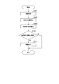
- FIG. 8 is a flowchart illustrating an example of a processing procedure in which the arithmetic device 300 detects a wear state of the guide wheel 941.
- the arithmetic device 300 performs the process of FIG. 8 for every predetermined period, for example.
- the image acquisition unit 310 acquires an image of the boundary of the guide wheel 941 captured by the two cameras 110 constituting the imaging unit pair 100 (step S101).
- the image acquisition unit 310 is an image of the boundary of the guide wheel 941, an image of the boundary on the first direction side along the vehicle traveling direction, and an image of the boundary on the opposite side to the first direction side. Two images are acquired.
- the side wheel detection unit 391 detects the position of the boundary image in each of the two images obtained in step S101 (step S102).
- the side wheel detection unit 391 detects an image of the boundary in the image, for example, by image matching, and obtains coordinates indicating the position of the detected boundary image in the image.
- the side wheel detection unit 391 calculates the distance between the boundaries in the guide wheel 941 (distance D11 in FIG. 4) (step S103).
- the side wheel detection unit 391 determines whether or not the distance between the boundaries obtained in step S103 is equal to or less than a threshold value (step S104). If it is determined that the value is larger than the threshold value (step S104: NO), the process of FIG. On the other hand, when it determines with the distance between boundaries being below a threshold value (step S104: YES), the side wheel detection part 391 outputs the warning which shows that the guide wheel 941 is worn out (step S111). . After step S111, the process of FIG. 8 ends.
- the processing procedure in which the arithmetic device 300 detects the wear state of the branch wheel 951 is the same as that for the guide wheel 941.
- FIG. 9 is a flowchart illustrating an example of a processing procedure in which the arithmetic device 300 detects the wear state of the traveling tire 921.
- the arithmetic device 300 performs the process of FIG. 9 for every predetermined period, for example.
- the distance information acquisition unit 320 acquires distance information obtained by the laser sensor 200 measuring the distance (step S201).
- the tire detection unit 392 calculates the depth of the groove provided on the surface of the traveling tire 921 as described above based on the distance information obtained in step S201 (step S202).
- step S203 determines whether the depth of the groove
- one of the cameras 110 constituting the imaging unit pair 100 is provided on the side of the track on which the vehicle 900 travels and is installed so as to image the inside of the track via the telecentric lens 111.
- the other of the cameras 110 constituting the imaging unit pair 100 is provided in the vehicle traveling direction with respect to the one camera 110 on the side of the track on which the vehicle 900 travels, and images the inside of the track via the telecentric lens 111. It is installed as follows.
- the image acquisition unit 310 is an image of the boundary of the guide wheel 941 captured by the camera 110 and is a boundary image on the first direction side along the vehicle traveling direction, and an image of the boundary of the guide wheel 941. An image of a boundary between the one direction side and the opposite side is acquired.
- the side wheel detection unit 391 detects the wear state of the guide wheel 941 based on the position of the boundary indicated by the image acquired by the image acquisition unit 310.
- the wear inspection apparatus 1 can automatically monitor the wear state of the guide wheel 941.
- the detection of the wear state of the guide wheel 941, which is one of the parts of the vehicle can be made efficient. Since the camera 110 includes the telecentric lens 111, the side wheel detection unit 391 does not need to perform correction based on the position of the subject in the depth direction with respect to the image captured by the camera 110, and between the boundaries of the guide wheels 941. Can be calculated. In this respect, it is possible to prevent an increase in the processing load of the side wheel detection unit 391.
- the two cameras 110 image the boundary of the guide wheel 941, respectively, so that the boundary on both sides of the guide wheel 941 can be imaged without using a telecentric lens having a large aperture. Since it is not necessary to use a telecentric lens having a large aperture, the equipment cost can be suppressed, and the enlargement of the camera 110 can be avoided.
- Laser sensor 200 is provided below the trajectory of vehicle 900 and measures the distance to an object located above that has an inclination in the vehicle traveling direction with respect to the vertical direction.
- the tire detection unit 392 detects the wear state of the traveling tire 921 based on the distance between the laser sensor 200 and the traveling tire 921 measured by the laser sensor 200.
- the wear inspection apparatus 1 can automatically monitor the wear state of the traveling tire 921.
- the wear inspection apparatus 1 it is possible to improve the efficiency of detecting the wear state of the traveling tire 921 that is one of the parts of the vehicle.
- the laser sensor 200 measures the distance from the traveling tire 921 above the inclination in the vehicle traveling direction with respect to the vertical direction, so that the laser sensor 200 is in a state where the traveling tire 921 is not in contact with the ground. Therefore, the measurement can be performed in a state where the traveling tire 921 is not crushed by the weight.
- the tire detection unit 392 can calculate the depth of the groove of the traveling tire 921 more accurately than when the traveling tire 921 is calculated with the weight collapsed.
- the side wheel detection unit 391 may detect the degree of wear of the guide wheel 941 for a plurality of directions of the guide wheel 941 so that the uneven wear of the guide wheel 941 can be detected.
- FIG. 10 is an explanatory diagram showing an example of changing the direction of the guide wheel 941.
- an arrow A41 indicates the traveling direction of the vehicle 900.
- a plate 411 for rotating the guide wheel 941 and a plate 412 for rotating the branch wheel 951 are provided on the side of the track of the vehicle 900.
- the guide wheel 941 rotates in contact with the plate 411 and changes its direction.
- the branch wheel 951 rotates in contact with the plate 412 and changes its direction.
- the directions of the guide wheel 941 and the branch wheel 951 are changed by 90 degrees.
- the plate 411 corresponds to an example of a rotation mechanism.
- a total of four cameras 110-1 are provided in order to image the boundary on both sides of the guide wheel 941 before and after the guide wheel 941 changes its direction.
- two cameras 110-1 (camera 110-1a and camera 110-1b) that capture images in a state before the guide wheel 941 rotates in contact with the plate 411 and changes its orientation, This corresponds to an example of the first imaging unit and the second imaging unit.
- two cameras 110-1 (camera 110-1c and camera 110-1d) that capture images in a state after the guide wheel 941 rotates in contact with the plate 411 and changes its orientation, This corresponds to an example of the third imaging unit and the fourth imaging unit.
- the side wheel detection unit 391 detects the wear state based on the image of the boundary before the guide wheel 941 rotates, which is captured by the cameras 110-1a and 110-1b. Further, the side wheel detection unit 391 detects the wear state based on an image of the boundary after the guide wheel 941 rotates, which is captured by the camera 110-1c and the camera 110-1d.
- the camera 110-1 images the boundary on both sides of the guide wheel 941 before and after the guide wheel 941 changes its direction.
- the side wheel detection unit 391 can calculate the length between the boundaries for a plurality of directions of the guide wheel 941 (two directions in the example of FIG. 10).
- the possibility that the side wheel detection unit 391 can detect the wear of the guide wheel 941 increases.
- the side wheel detection unit 391 may detect the degree of wear of the guide wheel 941 with respect to three or more directions of the guide wheel 941. Thereby, even when the guide wheel 941 is unevenly worn, the possibility that the side wheel detector 391 can detect the wear of the guide wheel 941 is further increased.
- the side wheel detection unit 391 may detect the degree of wear for the branching wheel 951 as well as the guide wheel 941 in a plurality of directions.
- a total of four cameras 110-2 are provided for imaging the boundary on both sides of the branching wheel 951 before and after the branching wheel 951 changes its direction.
- the camera 110-2 captures the boundary on both sides of the branch wheel 951 before and after the branch wheel 951 changes its direction, so that the side wheel detection unit 391
- the length between the boundaries can be calculated for a plurality of directions (two directions in the example of FIG. 10). Thereby, even when the branched wheel 951 is unevenly worn, there is a high possibility that the side wheel detector 391 can detect the wear of the branched wheel 951.
- the side wheel detection unit 391 may detect the degree of wear of the branch wheel 951 in three or more directions of the branch wheel 951. Thereby, even when the branch wheel 951 is unevenly worn, the possibility that the side wheel detector 391 can detect the wear of the branch wheel 951 is further increased.
- FIG. 11 is a schematic block diagram showing a functional configuration of a wear inspection apparatus 2 that is a first modification of the wear inspection apparatus 1 in the present embodiment.
- the wear inspection device 2 includes a camera 110 and an arithmetic device 500.
- the camera 110 includes a telecentric lens 111 and an image sensor 112.
- the arithmetic device 500 includes an image acquisition unit 310, a storage unit 380, and a calculation unit 590.
- the calculation unit 590 includes a side wheel detection unit 391. Two cameras 110 are paired to form an imaging unit pair 100.
- the number of imaging unit pairs 100 included in the wear inspection apparatus 1 may be one or more.
- the wear inspection apparatus 2 includes each unit for detecting at least one of wear of the guide wheel 941 and wear of the branch wheel 951. On the other hand, the wear inspection device 2 does not include each part for detecting wear of the traveling tire 921. Specifically, the wear inspection device 2 does not include the laser sensor 200, the distance information acquisition unit 320, and the tire detection unit 392 among the units included in the wear inspection device 1.
- one of the cameras 110 constituting the imaging unit pair 100 is provided on the side of the track on which the vehicle 900 travels, and the track of the track is connected via the telecentric lens 111. It is installed so that the inside can be imaged.
- the other of the cameras 110 constituting the imaging unit pair 100 is provided in the vehicle traveling direction with respect to the one camera 110 on the side of the track on which the vehicle 900 travels, and images the inside of the track via the telecentric lens 111. It is installed as follows.
- the image acquisition unit 310 is an image of the boundary of the guide wheel 941 captured by the camera 110 and is a boundary image on the first direction side along the vehicle traveling direction, and an image of the boundary of the guide wheel 941. An image of a boundary between the one direction side and the opposite side is acquired.
- the side wheel detection unit 391 detects the wear state of the guide wheel 941 based on the position of the boundary indicated by the image acquired by the image acquisition unit 310.
- the wear inspection apparatus 2 can automatically monitor the wear state of the guide wheel 941.
- the wear inspection apparatus 2 it is possible to improve the efficiency of detecting the wear state of the guide wheel 941 that is one of the parts of the vehicle. Since the camera 110 includes the telecentric lens 111, the side wheel detection unit 391 does not need to perform correction based on the position of the subject in the depth direction with respect to the image captured by the camera 110, and between the boundaries of the guide wheels 941. Can be calculated. In this respect, it is possible to prevent an increase in the processing load of the side wheel detection unit 391.
- the two cameras 110 image the boundary of the guide wheel 941, respectively, so that the boundary on both sides of the guide wheel 941 can be imaged without using a telecentric lens having a large aperture. Since it is not necessary to use a telecentric lens having a large aperture, the equipment cost can be suppressed, and the enlargement of the camera 110 can be avoided.
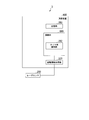
- FIG. 12 is a schematic block diagram showing a functional configuration of a wear inspection apparatus 3 which is a second modification of the wear inspection apparatus 1 in the present embodiment.
- the wear inspection device 3 includes a laser sensor 200 and an arithmetic device 600.
- the arithmetic device 600 includes a distance information acquisition unit 320, a storage unit 380, and a calculation unit 690.
- the calculation unit 690 includes a tire detection unit 392. 12, parts having the same functions corresponding to the respective parts in FIG. 1 are denoted by the same reference numerals (200, 320, 380, 392), and description thereof is omitted.
- the wear inspection device 3 includes various parts for detecting wear of the traveling tire 921.
- the wear inspection device 3 does not include each part for detecting the wear of the guide wheel 941 and the wear of the branch wheel 951. Specifically, the wear inspection device 3 does not include the camera 110, the image acquisition unit 310, and the side wheel detection unit 391 among the units included in the wear inspection device 1.
- the laser sensor 200 is provided below the track of the vehicle 900, and is positioned up to an object positioned above the vehicle in the vehicle traveling direction with respect to the vertical direction. Measure distance.
- the tire detection unit 392 detects the wear state of the traveling tire 921 based on the distance between the laser sensor 200 and the traveling tire 921 measured by the laser sensor 200.
- the wear inspection apparatus 3 can automatically monitor the wear state of the traveling tire 921.
- the wear inspection apparatus 3 it is possible to improve the efficiency of detecting the wear state of the traveling tire 921 that is one of the parts of the vehicle.
- the laser sensor 200 measures the distance from the traveling tire 921 above the inclination in the vehicle traveling direction with respect to the vertical direction, so that the laser sensor 200 is in a state where the traveling tire 921 is not in contact with the ground. Therefore, the measurement can be performed in a state where the traveling tire 921 is not crushed by the weight.
- the tire detection unit 392 can calculate the depth of the groove of the traveling tire 921 more accurately than when the traveling tire 921 is calculated with the weight collapsed.
- a program for realizing all or part of the functions of the arithmetic devices 300, 500 and 600 is recorded on a computer-readable recording medium, and the program recorded on the recording medium is read into a computer system and executed. You may process each part by.
- the “computer system” here includes an OS and hardware such as peripheral devices.
- the “computer system” includes a homepage providing environment (or display environment) if a WWW system is used.
- “Computer-readable recording medium” refers to a portable medium such as a flexible disk, a magneto-optical disk, a ROM, and a CD-ROM, and a storage device such as a hard disk built in a computer system.
- Computer-readable recording medium means a program that dynamically holds a program for a short time, such as a communication line when transmitting a program via a network such as the Internet or a communication line such as a telephone line.
- a volatile memory in a computer system that serves as a server or a client in this case includes a program that holds a program for a certain period of time.
- the program may be a program for realizing a part of the functions described above, or may be a program capable of realizing the functions described above in combination with a program already recorded in a computer system.
- the present invention provides a first imaging unit that is provided on a side of a track on which a vehicle with guide wheels provided on the side travels, and that images the inside of the track via a telecentric lens, and a side of the track.
- a second imaging unit that is provided in the vehicle traveling direction with respect to the first imaging unit and that images the inside of the track via a telecentric lens; and an image of a boundary between the guide wheels captured by the first imaging unit.
- An image acquisition unit that acquires an image of the boundary between the first direction side and the opposite side, and a guide that detects the wear state of the guide wheel based on the position of the boundary indicated by the image acquired by the image acquisition unit A wheel detector.
- An inspection apparatus ADVANTAGE OF THE INVENTION According to this invention, the detection of the wear condition of the components of a vehicle can be made efficient.
Landscapes
- Engineering & Computer Science (AREA)
- Physics & Mathematics (AREA)
- General Physics & Mathematics (AREA)
- Mechanical Engineering (AREA)
- Health & Medical Sciences (AREA)
- Biomedical Technology (AREA)
- General Health & Medical Sciences (AREA)
- Transportation (AREA)
- Length Measuring Devices By Optical Means (AREA)
- Platform Screen Doors And Railroad Systems (AREA)
Abstract
この摩耗検査装置は、側方に案内輪が設けられた車両が走行する軌道の側方に設けられて、テレセントリックレンズを介して前記軌道の内側を撮像する第1撮像部と、前記軌道の側方において前記第1撮像部に対して車両進行方向に設けられて、テレセントリックレンズを介して前記軌道の内側を撮像する第2撮像部と、前記第1撮像部が撮像した前記案内輪の境界の画像であって車両進行方向に沿った第1方向側における境界の画像と、前記第1撮像部による前記画像の撮像と同時刻に前記第2撮像部が撮像した前記案内輪の境界の画像であって前記第1方向側と逆側における境界の画像とを取得する画像取得部と、前記画像取得部が取得した画像にて示される境界の位置に基づいて、前記案内輪の摩耗状況を検知する案内輪用検知部と、を備える。
Description
本発明は、摩耗検査装置、摩耗検査方法及びプログラムに関する。
本願は、2015年2月27日に、日本に出願された特願2015-038661号に基づき優先権を主張し、その内容をここに援用する。
本願は、2015年2月27日に、日本に出願された特願2015-038661号に基づき優先権を主張し、その内容をここに援用する。
鉄道や新交通システムなどにおいて、車両に用いられている部品の摩耗の検査は、一般に手作業で行われている。
例えば、新交通システムの車両に用いられ消耗する部品として、走行用タイヤ、パンタグラフ、案内輪および分岐輪が挙げられる。これらの部品について、走行用タイヤの溝の深さ、パンタグラフの摩耗量、案内輪の直径、および、分岐輪の直径を、ノギス等を用いて手作業で測定し、手作業で測定結果をデータベースに入力するといった運用がなされる場合がある。これら測定作業や測定結果の入力作業に人件費がかかり、作業の効率化が望まれる。
例えば、新交通システムの車両に用いられ消耗する部品として、走行用タイヤ、パンタグラフ、案内輪および分岐輪が挙げられる。これらの部品について、走行用タイヤの溝の深さ、パンタグラフの摩耗量、案内輪の直径、および、分岐輪の直径を、ノギス等を用いて手作業で測定し、手作業で測定結果をデータベースに入力するといった運用がなされる場合がある。これら測定作業や測定結果の入力作業に人件費がかかり、作業の効率化が望まれる。
車両に用いられる部品の摩耗の検査に関連して、特許文献1に記載の、摺り板の摩耗量自動計測システムでは、車庫内を移動中の車両を対象とし、そのパンタグラフを検出した検出信号により、摺り板の摩耗量を非接触で自動計測する。特許文献1では、これにより、パンタグラフ保守者の安全と省力化に寄与するとされている。
パンタグラフに限らず他の部品についても、摩耗状況の検知を効率化できることが望ましい。
本発明は、車両の部品の摩耗状況の検知を効率化することができる摩耗検査装置、摩耗検査方法及びプログラムを提供する。
本発明の第1の態様によれば、摩耗検査装置は、側方に案内輪が設けられた車両が走行する軌道の側方に設けられて、テレセントリックレンズを介して前記軌道の内側を撮像する第1撮像部と、前記軌道の側方において前記第1撮像部に対して車両進行方向に設けられて、テレセントリックレンズを介して前記軌道の内側を撮像する第2撮像部と、前記第1撮像部が撮像した前記案内輪の境界の画像であって車両進行方向に沿った第1方向側(すなわち、車両進行方向一方側)における境界の画像と、前記第1撮像部による前記画像の撮像と同時刻に前記第2撮像部が撮像した前記案内輪の境界の画像であって前記第1方向側と逆側(すなわち、車両進行方向他方側)における境界の画像とを取得する画像取得部と、前記画像取得部が取得した画像にて示される境界の位置に基づいて、前記案内輪の摩耗状況を検知する案内輪用検知部と、を備える。
側方に案内輪が設けられた車両が走行する軌道の側方に設けられて、テレセントリックレンズを介して前記軌道の内側を撮像する第3撮像部と、前記軌道の側方において前記第3撮像部に対して車両進行方向に設けられて、テレセントリックレンズを介して前記軌道の内側を撮像する第4撮像部と、をさらに備え、前記軌道の側方に、前記案内輪に接して前記案内輪を回転させる回転機構が設けられており、前記第1撮像部、前記第2撮像部は、いずれも、前記回転機構が前記案内輪を回転させる前に前記案内輪における境界の画像を撮像する位置に設けられており、前記第3撮像部、前記第4撮像部は、いずれも、前記回転機構が前記案内輪を回転させた後に前記案内輪における境界の画像を撮像する位置に設けられており、前記画像取得部は、前記第3撮像部が撮像した前記案内輪の境界の画像であって車両進行方向に沿った第1方向側における境界の画像と、前記第3撮像部による前記画像の撮像と同時刻に前記第4撮像部が撮像した、前記案内輪の境界の画像であって前記第1方向側と逆側における境界の画像とをさらに取得し、前記案内輪用検知部は、前記第1撮像部が撮像した画像、前記第2撮像部が撮像した画像それぞれにて示される境界の位置に基づいて前記案内輪の摩耗状況を検知し、さらに、前記第3撮像部が撮像した画像、前記第4撮像部が撮像した画像それぞれにて示される境界の位置に基づいて前記案内輪の摩耗状況を検知するようにしてもよい。
前記軌道の下方に設けられて、鉛直方向に対して車両進行方向に傾きを有する上方に位置する物までの距離を測定する距離測定部と、前記距離測定部が測定した、前記距離測定部と前記車両の下方に設けられた走行用タイヤとの距離に基づいて、前記走行用タイヤの摩耗状況を検知するタイヤ用検知部と、をさらに備えるようにしてもよい。
本発明の第2の態様によれば、摩耗検査装置は、車両の下方に走行用タイヤが設けられた交通システムの軌道の下方に設けられて、鉛直方向に対して車両進行方向に傾きを有する上方に位置する物までの距離を測定する距離測定部と、前記距離測定部が測定した、前記距離測定部と前記車両の走行用タイヤとの距離に基づいて、前記走行用タイヤの摩耗状況を検知するタイヤ用検知部と、を備える。
本発明の第3の態様によれば、摩耗検査方法は、側方に案内輪が設けられた車両が走行する軌道の側方に設けられて、テレセントリックレンズを介して前記軌道の内側を撮像する第1撮像部と、前記軌道の側方において前記第1撮像部に対して車両進行方向に設けられて、テレセントリックレンズを介して前記軌道の内側を撮像する第2撮像部と、を備える摩耗検査装置の摩耗検査方法であって、前記第1撮像部が撮像した前記案内輪の境界の画像であって車両進行方向に沿った第1方向側における境界の画像と、前記第1撮像部による前記画像の撮像と同時刻に前記第2撮像部が撮像した前記案内輪の境界の画像であって前記第1方向側と逆側における境界の画像とを取得し、前記画像取得ステップにて取得した画像にて示される境界の位置に基づいて、前記案内輪の摩耗状況を検知する。
本発明の第4の態様によれば、プログラムは、側方に案内輪が設けられた車両が走行する軌道の側方に設けられて、テレセントリックレンズを介して前記軌道の内側を撮像する第1撮像部と、前記軌道の側方において前記第1撮像部に対して車両進行方向に設けられて、テレセントリックレンズを介して前記軌道の内側を撮像する第2撮像部と、を備える摩耗検査装置に用いられるコンピュータに、前記第1撮像部が撮像した前記案内輪の境界の画像であって車両進行方向に沿った第1方向側における境界の画像と、前記第1撮像部による前記画像の撮像と同時刻に前記第2撮像部が撮像した前記案内輪の境界の画像であって前記第1方向側と逆側における境界の画像とを取得させ、前記画像取得ステップにて取得した画像にて示される境界の位置に基づいて、前記案内輪の摩耗状況を検知させるためのプログラムである。
上記した摩耗検査装置、摩耗検査方法及びプログラムによれば、車両の部品の摩耗状況の検知を効率化することができる。
以下、本発明の実施形態を説明するが、以下の実施形態は請求の範囲にかかる発明を限定しない。また、実施形態の中で説明されている特徴の組み合わせの全てが発明の解決手段に必須であるとは限らない。
図1は、本発明の一実施形態における摩耗検査装置の機能構成を示す概略ブロック図である。図1において、摩耗検査装置1は、カメラ110と、レーザセンサ200と、演算装置300とを備える。カメラ110は、テレセントリックレンズ111と、撮像素子112とを備える。演算装置300は、画像取得部310と、距離情報取得部320と、記憶部380と、演算部390とを備える。演算部390は、案内輪分岐輪摩耗状況検知部(以下、側方輪用検知部と称する)391と、タイヤ摩耗状況検知部(以下、タイヤ用検知部と称する)392とを備える。
2つのカメラ110が対になって撮像部対100を構成している。摩耗検査装置1が備える撮像部対100の数は1つ以上であればよい。
図1は、本発明の一実施形態における摩耗検査装置の機能構成を示す概略ブロック図である。図1において、摩耗検査装置1は、カメラ110と、レーザセンサ200と、演算装置300とを備える。カメラ110は、テレセントリックレンズ111と、撮像素子112とを備える。演算装置300は、画像取得部310と、距離情報取得部320と、記憶部380と、演算部390とを備える。演算部390は、案内輪分岐輪摩耗状況検知部(以下、側方輪用検知部と称する)391と、タイヤ摩耗状況検知部(以下、タイヤ用検知部と称する)392とを備える。
2つのカメラ110が対になって撮像部対100を構成している。摩耗検査装置1が備える撮像部対100の数は1つ以上であればよい。
摩耗検査装置1は、交通システムの車両に設けられた案内輪の摩耗、分岐輪の摩耗、及び走行用タイヤの摩耗を検査する装置である。ここで、図2を参照して案内輪、分岐輪及び走行用タイヤの配置例について説明する。
図2は、車両の下部を正面から見た外形の概略を示す外観図である。図2に示す車両900において、車両本体910の左右それぞれに、軸922を介して走行用タイヤ921が設けられており、走行用タイヤ921は路面に接している。車両本体910の左右それぞれに支持体930が設けられている。支持体930には、軸942を介して案内輪941が設けられている。支持体930には、軸952を介して分岐輪951が設けられている。
図2は、車両の下部を正面から見た外形の概略を示す外観図である。図2に示す車両900において、車両本体910の左右それぞれに、軸922を介して走行用タイヤ921が設けられており、走行用タイヤ921は路面に接している。車両本体910の左右それぞれに支持体930が設けられている。支持体930には、軸942を介して案内輪941が設けられている。支持体930には、軸952を介して分岐輪951が設けられている。
走行用タイヤ921が軸922を中心に回転することで、車両900が走行する。案内輪941は、車両900が走行する軌道の側方に設けられたガイドレールに接して車両900の進行方向を制限することで、車両900を軌道に沿って走行させる。分岐輪951は、軌道の分岐点において、軌道の側方に設けられたガイドレールに接して車両900の進行方向を制限することで、分岐点における車両900の進行方向を制御する。
このように、走行用タイヤ921は路面との接触により摩耗する。案内輪941、分岐輪951はいずれも、ガイドレールとの接触により摩耗する。
このように、走行用タイヤ921は路面との接触により摩耗する。案内輪941、分岐輪951はいずれも、ガイドレールとの接触により摩耗する。
図2には、カメラ110とレーザセンサ200との配置例が示されている。カメラ110としてカメラ110-1及び110-2が、軌道の側方に、軌道の内側を撮像するように設けられている。カメラ110-1は、案内輪941を水平方向から撮像する高さに設けられている。カメラ110-1が撮像する画像は、側方輪用検知部391が案内輪941の摩耗状況を判定するために用いられる。
カメラ110-2は、分岐輪951を水平方向から撮像する高さに設けられている。カメラ110-2が撮像する画像は、側方輪用検知部391が分岐輪951の摩耗状況を判定するために用いられる。
レーザセンサ200は、路面に穴を設けて設置されている。レーザセンサ200は、後述するように、鉛直方向に対して車両900の進行方向に傾きを有する向きに設置されている。
カメラ110-2は、分岐輪951を水平方向から撮像する高さに設けられている。カメラ110-2が撮像する画像は、側方輪用検知部391が分岐輪951の摩耗状況を判定するために用いられる。
レーザセンサ200は、路面に穴を設けて設置されている。レーザセンサ200は、後述するように、鉛直方向に対して車両900の進行方向に傾きを有する向きに設置されている。
カメラ110は、車両900が走行する軌道の側方に設けられて、軌道の内側を撮像する。特に、カメラ110のうちカメラ110-1は、上記のように案内輪941を撮像する。カメラ110のうちカメラ110-2は、上記のように分岐輪951を撮像する。カメラ110が設けられる軌道は、車両900が通常の運行において走行する軌道であってもよいし、検査専用の軌道であってもよい。
テレセントリックレンズ111は、カメラ110の外界からの光を撮像素子112の位置で集光させて被写体の像を結ばせる。
図3は、テレセントリックレンズ111における主光線の例を示す説明図である。図3において、テレセントリックレンズ111は、レンズ本体121と絞り122とを備えている。絞り122は、レンズ本体121の焦点P11の位置に設けられており、これにより、主光線がレンズ光軸に対して平行な物体側テレセントリックとなっている。図3では、線L11がレンズ光軸を示し、線L12、L13がいずれも主光線の例を示している。
主光線を示す線L12、L13のいずれも、レンズ光軸を示す線L11と物体側(被写体側)において平行になっている。
カメラ110がテレセントリックレンズ111を備えることで、被写体の位置がカメラ110の奥行き方向に変化しても、撮像画像における被写体の像の位置が変化しない。
図3は、テレセントリックレンズ111における主光線の例を示す説明図である。図3において、テレセントリックレンズ111は、レンズ本体121と絞り122とを備えている。絞り122は、レンズ本体121の焦点P11の位置に設けられており、これにより、主光線がレンズ光軸に対して平行な物体側テレセントリックとなっている。図3では、線L11がレンズ光軸を示し、線L12、L13がいずれも主光線の例を示している。
主光線を示す線L12、L13のいずれも、レンズ光軸を示す線L11と物体側(被写体側)において平行になっている。
カメラ110がテレセントリックレンズ111を備えることで、被写体の位置がカメラ110の奥行き方向に変化しても、撮像画像における被写体の像の位置が変化しない。
側方輪用検知部391が案内輪941の摩耗状況を判定するために、カメラ110が案内輪941の側方から全体を撮像し、案内輪941の大きさ(直径)を測定することが考えられる。しかしながら、案内輪941の全体を撮像するためには、テレセントリックレンズ111として大口径のテレセントリックレンズが必要になる。口径の大きいテレセントリックレンズを用いると、設備コストがかかり、また、カメラ110の設置に大きなスペースを要することが考えられる。
そこで、摩耗検査装置1では、2つのカメラ110が対になった撮像部対100が、案内輪941の左右両側の境界を同時刻に撮像する。この点について、図4を参照して説明する。
そこで、摩耗検査装置1では、2つのカメラ110が対になった撮像部対100が、案内輪941の左右両側の境界を同時刻に撮像する。この点について、図4を参照して説明する。
図4は、カメラ110による案内輪941及び分岐輪951の撮像箇所の例を示す説明図である。カメラ110-1a及び110-1bは、案内輪941を撮像している。カメラ110-2a及び110-2bは、分岐輪951を撮像している。矢印A11は、車両900の進行方向を示している。
カメラ110-1a、110-1bのうちいずれか一方が第1撮像部の例に該当し、案内輪941の境界の画像であって車両進行方向に沿った第1方向側における境界の画像を撮像する。カメラ110-1a、110-1bのうち他方が第2撮像部の例に該当し、案内輪941の境界の画像であって前記第1方向側と逆側における境界の画像を撮像する。具体的には、カメラ110-1aは、案内輪941の車両進行方向前方の境界の画像を撮像し、カメラ110-1bは、案内輪941の車両進行方向後方の境界の画像を撮像する。カメラ110-1aは、カメラ110-1bに対して、車両進行方向に離間して設けられている。カメラ110-1aとカメラ110-1bとは同時刻に撮像を行う。但し、カメラ110-1aの撮像タイミングとカメラ110-1bの撮像タイミングとは厳密に同時である必要は無く、ほぼ同時であればよい。
カメラ110-1aが撮像した画像、および、カメラ110-1bが撮像した画像から、側方輪用検知部391の両側の境界間の距離D11を算出することができる。具体的には、側方輪用検知部391は、カメラ110-1aが撮像した画像、および、カメラ110-1bが撮像した画像から、それぞれ、案内輪941の境界の像を検出する。側方輪用検知部391は、カメラ110-1aと110-1bの位置関係(特に、カメラ110-1aと110-1bとの間の距離)、および画像の倍率(拡大縮小率)について既知であり、検出した境界の像の、画像内における位置に基づいて、距離D11を算出する。
カメラ110-1a及び110-1bがテレセントリックレンズ111を備えていることで、側方輪用検知部391は、カメラ110から見た案内輪941の奥行き方向の位置に応じて距離の補正を行う必要無しに、距離D11を算出することができる。
カメラ110-1a及び110-1bがテレセントリックレンズ111を備えていることで、側方輪用検知部391は、カメラ110から見た案内輪941の奥行き方向の位置に応じて距離の補正を行う必要無しに、距離D11を算出することができる。
カメラ110-2a、110-2bは、それぞれ、分岐輪951の境界の画像であって車両進行方向に沿った第1方向側における境界の画像、分岐輪951の境界の画像であって前記第1方向側と逆側における境界の画像を撮像する。具体的には、カメラ110-2aは、分岐輪951の車両進行方向前方の境界の画像を撮像し、カメラ110-2bは、分岐輪951の車両進行方向後方の境界の画像を撮像する。カメラ110-2aは、カメラ110-2bに対して、車両進行方向に設けられている。
カメラ110-2aが撮像した画像、および、カメラ110-2bが撮像した画像から、分岐輪951の両側の境界間の距離D12を算出することができる。具体的には、側方輪用検知部391は、カメラ110-2aが撮像した画像、および、カメラ110-2bが撮像した画像から、それぞれ、分岐輪951の境界の像を検出する。側方輪用検知部391は、カメラ110-2aと110-2bの位置関係(特に、カメラ110-2aと110-2bとの間の距離)、および画像の倍率(拡大縮小率)について既知であり、検出した境界の像の、画像内における位置に基づいて、距離D12を算出する。
カメラ110-1a及び110-1bがテレセントリックレンズ111を備えていることで、側方輪用検知部391は、カメラ110から見た案内輪941の奥行き方向の位置に応じて距離の補正を行う必要無しに、距離D12を算出することができる。
カメラ110-1a及び110-1bがテレセントリックレンズ111を備えていることで、側方輪用検知部391は、カメラ110から見た案内輪941の奥行き方向の位置に応じて距離の補正を行う必要無しに、距離D12を算出することができる。
図5は、車両900を上から見た外形の概略を示す外観図である。図2を参照して説明したように、車両本体910の左右それぞれに支持体930が設けられており、支持体930には、案内輪941と分岐輪951とが設けられている。
カメラ110として、カメラ110-1a、110-1b、110-2a及び110-2bが、軌道の側方に、軌道の内側を撮像するように設けられている。図4を参照して説明したように、カメラ110-1a及び110-1bは、案内輪941を撮像している。カメラ110-2a及び110-2bは、分岐輪951を撮像している。矢印A21は、車両900の進行方向を示している。
カメラ110として、カメラ110-1a、110-1b、110-2a及び110-2bが、軌道の側方に、軌道の内側を撮像するように設けられている。図4を参照して説明したように、カメラ110-1a及び110-1bは、案内輪941を撮像している。カメラ110-2a及び110-2bは、分岐輪951を撮像している。矢印A21は、車両900の進行方向を示している。
車両本体910の各側面に複数の案内輪941及び分岐輪951が設けられている。例えば、カメラ110-1a、110-1bが常時、撮像を行うなど、案内輪941の境界がカメラ110自らの前に位置する毎に境界の画像を撮像するようにしてもよい。これにより、側方輪用検知部391は、複数の案内輪941について摩耗状況を判定することができる。また、例えば、カメラ110-2a、110-2bが常時、撮像を行うなど、分岐輪951の境界がカメラ110自らの前に位置する毎に境界の画像を撮像するようにしてもよい。これにより、側方輪用検知部391は、複数の分岐輪951について摩耗状況を判定することができる。
図5では、軌道の側方のうち一方側のみにカメラ110が設けられている場合の例を示しているが、軌道の両側の側方にカメラ110が設けられていてもよい。
図5では、軌道の側方のうち一方側のみにカメラ110が設けられている場合の例を示しているが、軌道の両側の側方にカメラ110が設けられていてもよい。
撮像素子112は、テレセントリックレンズ111が集光した光を光電変換して画像データを生成する。
レーザセンサ200は、距離測定部の例に該当し、レーザ照射方向にある物までの距離を測定する。特に、レーザセンサ200は、レーザ照射方向に走行用タイヤ921がある場合、レーザセンサ200と走行用タイヤ921の表面との距離を測定する。その際、レーザセンサ200は、走行用タイヤ921の幅方向に広がりのあるレーザ光を照射し、各部との距離を測定する。
レーザセンサ200は、距離測定部の例に該当し、レーザ照射方向にある物までの距離を測定する。特に、レーザセンサ200は、レーザ照射方向に走行用タイヤ921がある場合、レーザセンサ200と走行用タイヤ921の表面との距離を測定する。その際、レーザセンサ200は、走行用タイヤ921の幅方向に広がりのあるレーザ光を照射し、各部との距離を測定する。
図6は、レーザセンサ200の設置例を示す説明図である。図6において、路面のうち走行用タイヤ921が走行する位置に走行用タイヤ921の幅D21よりも狭い幅D22の穴が設けられ、穴の中に、レーザセンサ200が設けられている。レーザセンサ200は、走行用タイヤ921において幅D24の広がりを有するレーザ光を照射し、レーザセンサ200から各部までの距離を測定する。従って、レーザセンサ200は、走行用タイヤ921の幅方向に線状に、レーザセンサ200から各部までの距離を測定する。
例えば、走行用タイヤ921の幅D21が300ミリメートル(mm)程度であるのに対し、穴の幅D22は50ミリメートル程度である。レーザセンサ200は、レーザ光の照射距離が450ミリメートル程度となる走行用タイヤ921の位置において、250ミリメートル程度の幅D24について各部までの距離を測定する。
レーザセンサ200が測定する距離について走行用タイヤ921の幅方向の変化量(隣との差分)を求めることで、走行用タイヤ921の表面の凹凸を検出することができる。
これにより、タイヤ用検知部392は、走行用タイヤ921の表面に設けられた溝の深さを算出する。
レーザセンサ200が測定する距離について走行用タイヤ921の幅方向の変化量(隣との差分)を求めることで、走行用タイヤ921の表面の凹凸を検出することができる。
これにより、タイヤ用検知部392は、走行用タイヤ921の表面に設けられた溝の深さを算出する。
図6に示すように、レーザセンサ200は、軌道の下方に設けられて、鉛直方向に対して車両進行方向に傾きを有する上方に位置する走行用タイヤ921までの距離を測定するように設置されている。このように、レーザセンサ200は、鉛直方向に対して車両進行方向に傾きを有する向きに位置する走行用タイヤ921までの距離を測定する。その結果、レーザセンサ200は、走行用タイヤ921が地面に接していない状態、従って、走行用タイヤ921が重みで潰れていない状態で測定を行うことができる。
これにより、タイヤ用検知部392は、走行用タイヤ921の溝の深さを、走行用タイヤ921が重みで潰れた状態で算出する場合よりも正確に算出することができる。
これにより、タイヤ用検知部392は、走行用タイヤ921の溝の深さを、走行用タイヤ921が重みで潰れた状態で算出する場合よりも正確に算出することができる。
演算装置300は、カメラ110が撮像する画像に基づいて、案内輪941の摩耗状況及び分岐輪951の摩耗状況を検知する。また、演算装置300は、レーザセンサ200が検出する距離に基づいて、走行用タイヤ921の摩耗状況を検知する。
演算装置300は、例えばコンピュータを用いて構成される。
演算装置300は、例えばコンピュータを用いて構成される。
画像取得部310は、カメラ110が撮像した画像を取得する。特に、画像取得部310は、撮像部対100を成す2つのカメラ110が撮像する、案内輪941境界の画像であって車両進行方向に沿った第1方向側における境界の画像、および、前記第1方向側と逆側における境界の画像を取得する。また、画像取得部310は、撮像部対100を成す2つのカメラ110が撮像する、分岐輪951境界の画像であって車両進行方向に沿った第1方向側における境界の画像、および、前記第1方向側と逆側における境界の画像を取得する。
画像取得部310は、例えば、カメラ110の各々と通信を行って画像データを受信する通信回路として構成される。
画像取得部310は、例えば、カメラ110の各々と通信を行って画像データを受信する通信回路として構成される。
距離情報取得部320は、レーザセンサ200による距離測定の結果を示す距離情報を取得する。距離情報取得部320は、例えば、レーザセンサ200と通信を行って距離情報を受信する通信回路として構成される。
記憶部380は、演算装置300が備える記憶デバイスを用いて構成され、各種情報を記憶する。特に、記憶部380は、画像取得部310が取得した画像データや、距離情報取得部320が取得した距離情報を記憶する。
記憶部380は、演算装置300が備える記憶デバイスを用いて構成され、各種情報を記憶する。特に、記憶部380は、画像取得部310が取得した画像データや、距離情報取得部320が取得した距離情報を記憶する。
演算部390は、演算装置300の各部を制御して、各種演算など各種処理を行う。演算部390は、例えば演算装置300が備えるCPU(Central Processing Unit、中央処理装置)が記憶部380からプログラムを読み出して実行することで構成される。
側方輪用検知部391は、案内輪摩耗状況検知部(以下、案内輪用検知部と称する)の例に該当し、画像取得部310が取得した画像にて示される案内輪941の境界の位置に基づいて、案内輪941の摩耗状況を検知する。より具体的には、側方輪用検知部391は、撮像部対100を成す2つのカメラ110が撮像した、案内輪941の両側の境界の画像に基づいて、境界間の長さを算出し、得られた長さを閾値と比較して、警報を出力するか否かを判定する。側方輪用検知部391は、案内輪941の場合と同様に分岐輪951についても摩耗状況を検知する。
側方輪用検知部391は、案内輪摩耗状況検知部(以下、案内輪用検知部と称する)の例に該当し、画像取得部310が取得した画像にて示される案内輪941の境界の位置に基づいて、案内輪941の摩耗状況を検知する。より具体的には、側方輪用検知部391は、撮像部対100を成す2つのカメラ110が撮像した、案内輪941の両側の境界の画像に基づいて、境界間の長さを算出し、得られた長さを閾値と比較して、警報を出力するか否かを判定する。側方輪用検知部391は、案内輪941の場合と同様に分岐輪951についても摩耗状況を検知する。
図7は、カメラ110が撮像する画像と案内輪941との対応関係の例を示す説明図である。図7において、画像P21はカメラ110(例えば、図4のカメラ110-1a)が撮像した、案内輪941境界の画像であって車両進行方向に沿った第1方向側における境界の画像の例を示す。画像P21において、領域A31は、案内輪941の像以外の領域であり、領域A32は、案内輪941の像の領域である。距離D31は、案内輪941において領域A32に相当する部分の実際の幅を示す。側方輪用検知部391は、カメラ110が撮像する画像の倍率(拡大縮小率)を予め記憶しておき、画像P21における領域A32の幅を検出し、得られた幅をその倍率で除算することで距離D31を算出する。
画像P22はカメラ110(例えば、図4のカメラ110-1b)が撮像した、案内輪941における車両進行方向他方側の境界の画像の例を示す。画像P22において、領域A33は、案内輪941の像の領域であり、領域A34は、案内輪941の像の以外領域である。距離D32は、案内輪941において領域A33に相当する部分の実際の幅を示す。側方輪用検知部391は、画像P22における領域A33の幅を検出し、得られた幅を画像P22の倍率で除算することで距離D32を算出する。
距離D33は、画像P21と画像P22との隙間に相当する距離である。この距離D33は、2つのカメラ110が離間して設置された距離に応じた固定である。例えば、摩耗検査装置1のユーザが距離D33を登録しておき、記憶部380がその距離D33を予め記憶しておく。
側方輪用検知部391は、距離D31およびD32を算出し、距離D33を記憶部380から読み出して、距離D31、D32及びD33の合計を算出することで、案内輪941における境界間の幅(距離D11)を算出する。距離D11は、案内輪941の直径に相当する。
側方輪用検知部391は、距離D31およびD32を算出し、距離D33を記憶部380から読み出して、距離D31、D32及びD33の合計を算出することで、案内輪941における境界間の幅(距離D11)を算出する。距離D11は、案内輪941の直径に相当する。
そして、側方輪用検知部391は、算出した距離D11と所定の閾値とを比較し、距離D11が閾値以下であると判定すると、案内輪941が摩耗していることを示す警報を出力する。この閾値は、例えば、摩耗検査装置1のユーザが、案内輪941の仕様(特に、新品の案内輪941の直径)に基づいて値を決定し登録しておき、記憶部380がその閾値を予め記憶しておく。
側方輪用検知部391が警報を出力する態様は、色々な態様であってよい。例えば、演算装置300が備える表示装置が、側方輪用検知部391が出力する警報を表示するようにしてもよい。あるいは、側方輪用検知部391が出力する警報を、演算装置300が他の機器へ送信するようにしてもよい。
側方輪用検知部391が、案内輪941の摩耗状況の評価として、警報の出力に加えて、あるいは代えて、案内輪941の直径に相当する距離D11を出力するなど、案内輪941の摩耗の度合いを示す値を出力するようにしてもよい。
側方輪用検知部391が、案内輪941の摩耗状況の評価として、警報の出力に加えて、あるいは代えて、案内輪941の直径に相当する距離D11を出力するなど、案内輪941の摩耗の度合いを示す値を出力するようにしてもよい。
側方輪用検知部391は、分岐輪951についても同様に、境界間の距離を算出し、所定の閾値と比較する。そして、分岐輪951における境界間の距離が閾値以下であると判定すると、側方輪用検知部391は、分岐輪951が摩耗していることを示す警報を出力する。
案内輪941の場合と同様、分岐輪951についても、側方輪用検知部391が警報を出力する態様は、色々な態様であってよい。
案内輪941の場合と同様、分岐輪951についても、側方輪用検知部391が、分岐輪951の摩耗の度合いを示す値を出力するようにしてもよい。
案内輪941の場合と同様、分岐輪951についても、側方輪用検知部391が、分岐輪951の摩耗の度合いを示す値を出力するようにしてもよい。
タイヤ用検知部392は、レーザセンサ200が測定した、レーザセンサ200自らと走行用タイヤ921の表面との距離に基づいて、走行用タイヤ921の摩耗状況を検知する。より具体的には、レーザセンサ200は、図6を参照して説明したように、走行用タイヤ921の幅方向に線状に、レーザセンサ200自らと走行用タイヤ921の表面との距離を測定する。そして、タイヤ用検知部392は、レーザセンサ200が測定する距離について走行用タイヤ921の幅方向の変化量(隣との差分)を求めることで、走行用タイヤ921の表面の凹凸を検出する。これにより、タイヤ用検知部392は、走行用タイヤ921の表面に設けられた溝の深さを算出する。そして、タイヤ用検知部392は、得られた溝の深さと所定の閾値とを比較し、溝の深さが閾値以下であると判定すると、走行用タイヤ921が摩耗していることを示す警報を出力する。この閾値は、例えば、摩耗検査装置1のユーザが、走行用タイヤ921の仕様(特に、新品の走行用タイヤ921における溝の深さ)に基づいて値を決定し登録しておき、記憶部380がその閾値を予め記憶しておく。
タイヤ用検知部392が警報を出力する態様は、色々な態様であってよい。例えば、演算装置300が備える表示装置が、タイヤ用検知部392が出力する警報を表示するようにしてもよい。あるいは、タイヤ用検知部392が出力する警報を、演算装置300が他の機器へ送信するようにしてもよい。
タイヤ用検知部392が、走行用タイヤ921の摩耗状況の評価として、警報の出力に加えて、あるいは代えて、走行用タイヤ921の溝の深さを出力するなど、走行用タイヤ921の摩耗の度合いを示す値を出力するようにしてもよい。
タイヤ用検知部392が、走行用タイヤ921の摩耗状況の評価として、警報の出力に加えて、あるいは代えて、走行用タイヤ921の溝の深さを出力するなど、走行用タイヤ921の摩耗の度合いを示す値を出力するようにしてもよい。
次に、図8および図9を参照して、演算装置300の動作について説明する。
図8は、演算装置300が案内輪941の摩耗状況を検知する処理手順の例を示すフローチャートである。演算装置300は、例えば所定周期毎に図8の処理を行う。
図8の処理において、画像取得部310は、撮像部対100を構成する2つのカメラ110が撮像した、案内輪941の境界の画像を取得する(ステップS101)。上述したように、画像取得部310は、案内輪941の境界の画像であって車両進行方向に沿った第1方向側における境界の画像、及び、第1方向側と逆側における境界の画像の、2つの画像を取得する。
図8は、演算装置300が案内輪941の摩耗状況を検知する処理手順の例を示すフローチャートである。演算装置300は、例えば所定周期毎に図8の処理を行う。
図8の処理において、画像取得部310は、撮像部対100を構成する2つのカメラ110が撮像した、案内輪941の境界の画像を取得する(ステップS101)。上述したように、画像取得部310は、案内輪941の境界の画像であって車両進行方向に沿った第1方向側における境界の画像、及び、第1方向側と逆側における境界の画像の、2つの画像を取得する。
次に、側方輪用検知部391は、ステップS101で得られた2つの画像それぞれについて、画像内における境界の像の位置を検出する(ステップS102)。側方輪用検知部391は、例えば画像マッチングにより、画像内における境界の像を検出し、検出した境界の像の、画像内における位置を示す座標を求める。
そして、側方輪用検知部391は、図4を参照して説明したように、案内輪941における境界間の距離(図4の距離D11)を算出する(ステップS103)。
そして、側方輪用検知部391は、図4を参照して説明したように、案内輪941における境界間の距離(図4の距離D11)を算出する(ステップS103)。
そして、側方輪用検知部391は、ステップS103で得られた境界間の距離が閾値以下か否かを判定する(ステップS104)。閾値より大きいと判定した場合(ステップS104:NO)、図8の処理を終了する。
一方、境界間の距離が閾値以下であると判定した場合(ステップS104:YES)、側方輪用検知部391は、案内輪941が摩耗していることを示す警報を出力する(ステップS111)。
ステップS111の後、図8の処理を終了する。
演算装置300が分岐輪951の摩耗状況を検知する処理の手順も、案内輪941の場合と同様である。
一方、境界間の距離が閾値以下であると判定した場合(ステップS104:YES)、側方輪用検知部391は、案内輪941が摩耗していることを示す警報を出力する(ステップS111)。
ステップS111の後、図8の処理を終了する。
演算装置300が分岐輪951の摩耗状況を検知する処理の手順も、案内輪941の場合と同様である。
図9は、演算装置300が走行用タイヤ921の摩耗状況を検知する処理手順の例を示すフローチャートである。演算装置300は、例えば所定周期毎に図9の処理を行う。
図9の処理において、距離情報取得部320は、レーザセンサ200が距離を測定して得られた距離情報を取得する(ステップS201)。
次に、タイヤ用検知部392は、ステップS201で得られた距離情報に基づいて、上記のように走行用タイヤ921の表面に設けられた溝の深さを算出する(ステップS202)。
図9の処理において、距離情報取得部320は、レーザセンサ200が距離を測定して得られた距離情報を取得する(ステップS201)。
次に、タイヤ用検知部392は、ステップS201で得られた距離情報に基づいて、上記のように走行用タイヤ921の表面に設けられた溝の深さを算出する(ステップS202)。
そして、タイヤ用検知部392は、ステップS202で得られた溝の深さが閾値以下か否かを判定する(ステップS203)。閾値より大きいと判定した場合(ステップS203:NO)、図9の処理を終了する。
一方、溝の深さが閾値以下であると判定した場合(ステップS203:YES)、タイヤ用検知部392は、走行用タイヤ921が摩耗していることを示す警報を出力する(ステップS211)。
ステップS211の後、図9の処理を終了する。
一方、溝の深さが閾値以下であると判定した場合(ステップS203:YES)、タイヤ用検知部392は、走行用タイヤ921が摩耗していることを示す警報を出力する(ステップS211)。
ステップS211の後、図9の処理を終了する。
以上のように、撮像部対100を構成するカメラ110の一方は、車両900が走行する軌道の側方に設けられて、テレセントリックレンズ111を介して軌道の内側を撮像するように設置されている。撮像部対100を構成するカメラ110の他方は、車両900が走行する軌道の側方において一方のカメラ110に対して車両進行方向に設けられて、テレセントリックレンズ111を介して軌道の内側を撮像するように設置されている。
画像取得部310は、カメラ110が撮像した案内輪941の境界の画像であって車両進行方向に沿った第1方向側における境界の画像、および、案内輪941の境界の画像であって前記第1方向側と逆側における境界の画像を取得する。
そして、側方輪用検知部391は、画像取得部310が取得した画像にて示される境界の位置に基づいて、案内輪941の摩耗状況を検知する。
画像取得部310は、カメラ110が撮像した案内輪941の境界の画像であって車両進行方向に沿った第1方向側における境界の画像、および、案内輪941の境界の画像であって前記第1方向側と逆側における境界の画像を取得する。
そして、側方輪用検知部391は、画像取得部310が取得した画像にて示される境界の位置に基づいて、案内輪941の摩耗状況を検知する。
これにより、摩耗検査装置1では、案内輪941の摩耗状況を自動にて監視することができる。この点において、摩耗検査装置1によれば、車両の部品の1つである案内輪941の摩耗状況の検知を効率化することができる。
カメラ110がテレセントリックレンズ111を備えることで、側方輪用検知部391は、カメラ110が撮像した画像に対して奥行方向における被写体の位置に基づく補正を行う必要なしに、案内輪941の境界間の距離を算出することができる。この点において、側方輪用検知部391の処理負荷の増大を防止することができる。
カメラ110がテレセントリックレンズ111を備えることで、側方輪用検知部391は、カメラ110が撮像した画像に対して奥行方向における被写体の位置に基づく補正を行う必要なしに、案内輪941の境界間の距離を算出することができる。この点において、側方輪用検知部391の処理負荷の増大を防止することができる。
2つのカメラ110が、それぞれ案内輪941の境界を撮像することで、口径の大きいテレセントリックレンズを用いる必要なしに、案内輪941の両側の境界を撮像することができる。口径の大きいテレセントリックレンズを用いる必要がない点で、設備コストを抑制することができ、また、カメラ110の大型化を回避することができる。
レーザセンサ200は、車両900の軌道の下方に設けられて、鉛直方向に対して車両進行方向に傾きを有する上方に位置する物までの距離を測定する。そして、タイヤ用検知部392は、レーザセンサ200が測定した、レーザセンサ200と走行用タイヤ921との距離に基づいて、走行用タイヤ921の摩耗状況を検知する。
これにより、摩耗検査装置1では、走行用タイヤ921の摩耗状況を自動にて監視することができる。この点において、摩耗検査装置1によれば、車両の部品の1つである走行用タイヤ921の摩耗状況の検知を効率化することができる。
レーザセンサ200が、鉛直方向に対して車両進行方向に傾きを有する上方にて走行用タイヤ921との距離を測定することで、レーザセンサ200は、走行用タイヤ921が地面に接していない状態、従って、走行用タイヤ921が重みで潰れていない状態で測定を行うことができる。これにより、タイヤ用検知部392は、走行用タイヤ921の溝の深さを、走行用タイヤ921が重みで潰れた状態で算出する場合よりも正確に算出することができる。
レーザセンサ200が、鉛直方向に対して車両進行方向に傾きを有する上方にて走行用タイヤ921との距離を測定することで、レーザセンサ200は、走行用タイヤ921が地面に接していない状態、従って、走行用タイヤ921が重みで潰れていない状態で測定を行うことができる。これにより、タイヤ用検知部392は、走行用タイヤ921の溝の深さを、走行用タイヤ921が重みで潰れた状態で算出する場合よりも正確に算出することができる。
側方輪用検知部391が、案内輪941の偏摩耗を検知できるように、案内輪941の複数の向きについて、案内輪941の摩耗度合いを検知するようにしてもよい。
図10は、案内輪941の向きの変更の例を示す説明図である。図10において、矢印A41は、車両900の進行方向を示している。車両900の軌道の側方に、案内輪941を回転させるための板411と、分岐輪951を回転させるための板412とが設けられている。車両900の走行に伴って、案内輪941は板411に接して回転して向きを変える。車両900の走行に伴って、分岐輪951は板412に接して回転して向きを変える。図10の例では、案内輪941、分岐輪951とも向きを90度変化させている。板411は、回転機構の例に該当する。
図10は、案内輪941の向きの変更の例を示す説明図である。図10において、矢印A41は、車両900の進行方向を示している。車両900の軌道の側方に、案内輪941を回転させるための板411と、分岐輪951を回転させるための板412とが設けられている。車両900の走行に伴って、案内輪941は板411に接して回転して向きを変える。車両900の走行に伴って、分岐輪951は板412に接して回転して向きを変える。図10の例では、案内輪941、分岐輪951とも向きを90度変化させている。板411は、回転機構の例に該当する。
案内輪941が向きを変える前、向きを変えた後のそれぞれについて、案内輪941の両側の境界を撮像するためにカメラ110-1が2つずつ、合計4つ設けられている。
これら4つのカメラ110-1のうち、案内輪941が板411に接して回転して向きを変える前の状態で撮像する2つのカメラ110-1(カメラ110-1a及びカメラ110-1b)が、第1撮像部及び第2撮像部の例に該当する。4つのカメラ110-1のうち、案内輪941が板411に接して回転して向きを変えた後の状態で撮像する2つのカメラ110-1(カメラ110-1c及びカメラ110-1d)が、第3撮像部及び第4撮像部の例に該当する。
これら4つのカメラ110-1のうち、案内輪941が板411に接して回転して向きを変える前の状態で撮像する2つのカメラ110-1(カメラ110-1a及びカメラ110-1b)が、第1撮像部及び第2撮像部の例に該当する。4つのカメラ110-1のうち、案内輪941が板411に接して回転して向きを変えた後の状態で撮像する2つのカメラ110-1(カメラ110-1c及びカメラ110-1d)が、第3撮像部及び第4撮像部の例に該当する。
側方輪用検知部391は、カメラ110-1a、カメラ110-1bそれぞれが撮像した、案内輪941が回転する前の状態での境界の画像に基づいて摩耗状況を検出する。さらに、側方輪用検知部391は、カメラ110-1c、カメラ110-1dそれぞれが撮像した、案内輪941が回転した後の状態での境界の画像に基づいて摩耗状況を検出する。
このように、カメラ110-1が、案内輪941が向きを変える前、向きを変えた後のそれぞれについて、案内輪941の両側の境界を撮像する。これにより、側方輪用検知部391は、案内輪941の複数の向き(図10の例では2つの向き)について境界間の長さを算出することができる。これにより、案内輪941が偏摩耗している場合でも、側方輪用検知部391が、案内輪941の摩耗を検知できる可能性が高くなる。例えば、案内輪941の摩耗の大きさが所定の大きさ以上であるか否かを、側方輪用検知部391が判定できる可能性が高くなる。
側方輪用検知部391が、案内輪941の3つ以上の向きについて、案内輪941の摩耗度合いを検知するようにしてもよい。これにより、案内輪941が偏摩耗している場合でも、側方輪用検知部391が、案内輪941の摩耗を検知できる可能性が、さらに高くなる。
側方輪用検知部391が、案内輪941の3つ以上の向きについて、案内輪941の摩耗度合いを検知するようにしてもよい。これにより、案内輪941が偏摩耗している場合でも、側方輪用検知部391が、案内輪941の摩耗を検知できる可能性が、さらに高くなる。
側方輪用検知部391が、分岐輪951についても案内輪941の場合と同様、複数の向きについて摩耗度合いを検知するようにしてもよい。
図10において、分岐輪951が向きを変える前、向きを変えた後のそれぞれについて、分岐輪951の両側の境界を撮像するためにカメラ110-2が2つずつ、合計4つ設けられている。
カメラ110-2が、分岐輪951が向きを変える前、向きを変えた後のそれぞれについて、分岐輪951の両側の境界を撮像することで、側方輪用検知部391は、分岐輪951の複数の向き(図10の例では2つの向き)について境界間の長さを算出することができる。これにより、分岐輪951が偏摩耗している場合でも、側方輪用検知部391が、分岐輪951の摩耗を検知できる可能性が高くなる。
側方輪用検知部391が、分岐輪951の3つ以上の向きについて、分岐輪951の摩耗度合いを検知するようにしてもよい。これにより、分岐輪951が偏摩耗している場合でも、側方輪用検知部391が、分岐輪951の摩耗を検知できる可能性が、さらに高くなる。
図10において、分岐輪951が向きを変える前、向きを変えた後のそれぞれについて、分岐輪951の両側の境界を撮像するためにカメラ110-2が2つずつ、合計4つ設けられている。
カメラ110-2が、分岐輪951が向きを変える前、向きを変えた後のそれぞれについて、分岐輪951の両側の境界を撮像することで、側方輪用検知部391は、分岐輪951の複数の向き(図10の例では2つの向き)について境界間の長さを算出することができる。これにより、分岐輪951が偏摩耗している場合でも、側方輪用検知部391が、分岐輪951の摩耗を検知できる可能性が高くなる。
側方輪用検知部391が、分岐輪951の3つ以上の向きについて、分岐輪951の摩耗度合いを検知するようにしてもよい。これにより、分岐輪951が偏摩耗している場合でも、側方輪用検知部391が、分岐輪951の摩耗を検知できる可能性が、さらに高くなる。
摩耗検査装置が、案内輪941の摩耗、分岐輪951の摩耗、及び、走行用タイヤ921の摩耗の全てを検知する必要はなく、これらのうちいずれか1つまたは2つを検知するようにしてもよい。
図11は、本実施形態における摩耗検査装置1の第1の変形例である摩耗検査装置2の機能構成を示す概略ブロック図である。図11において、摩耗検査装置2は、カメラ110と、演算装置500とを備える。カメラ110は、テレセントリックレンズ111と、撮像素子112とを備える。演算装置500は、画像取得部310と、記憶部380と、演算部590とを備える。演算部590は、側方輪用検知部391を備える。
2つのカメラ110が対になって撮像部対100を構成している。摩耗検査装置1が備える撮像部対100の数は1つ以上であればよい。
図11は、本実施形態における摩耗検査装置1の第1の変形例である摩耗検査装置2の機能構成を示す概略ブロック図である。図11において、摩耗検査装置2は、カメラ110と、演算装置500とを備える。カメラ110は、テレセントリックレンズ111と、撮像素子112とを備える。演算装置500は、画像取得部310と、記憶部380と、演算部590とを備える。演算部590は、側方輪用検知部391を備える。
2つのカメラ110が対になって撮像部対100を構成している。摩耗検査装置1が備える撮像部対100の数は1つ以上であればよい。
図11において、図1の各部に対応して同様の機能を有する部分には同一の符号(100、110、111、112、310、380、391)を付して説明を省略する。
摩耗検査装置2は、案内輪941の摩耗および分岐輪951の摩耗のうち少なくとも一方を検知するための各部を備えている。一方、摩耗検査装置2は、走行用タイヤ921の摩耗を検知するための各部を備えていない。具体的には、摩耗検査装置2は、摩耗検査装置1が備える各部のうち、レーザセンサ200と、距離情報取得部320と、タイヤ用検知部392とを備えていない。
摩耗検査装置2は、案内輪941の摩耗および分岐輪951の摩耗のうち少なくとも一方を検知するための各部を備えている。一方、摩耗検査装置2は、走行用タイヤ921の摩耗を検知するための各部を備えていない。具体的には、摩耗検査装置2は、摩耗検査装置1が備える各部のうち、レーザセンサ200と、距離情報取得部320と、タイヤ用検知部392とを備えていない。
摩耗検査装置1の場合と同様、摩耗検査装置2において、撮像部対100を構成するカメラ110の一方は、車両900が走行する軌道の側方に設けられて、テレセントリックレンズ111を介して軌道の内側を撮像するように設置されている。撮像部対100を構成するカメラ110の他方は、車両900が走行する軌道の側方において一方のカメラ110に対して車両進行方向に設けられて、テレセントリックレンズ111を介して軌道の内側を撮像するように設置されている。
画像取得部310は、カメラ110が撮像した案内輪941の境界の画像であって車両進行方向に沿った第1方向側における境界の画像、および、案内輪941の境界の画像であって前記第1方向側と逆側における境界の画像を取得する。
そして、側方輪用検知部391は、画像取得部310が取得した画像にて示される境界の位置に基づいて、案内輪941の摩耗状況を検知する。
画像取得部310は、カメラ110が撮像した案内輪941の境界の画像であって車両進行方向に沿った第1方向側における境界の画像、および、案内輪941の境界の画像であって前記第1方向側と逆側における境界の画像を取得する。
そして、側方輪用検知部391は、画像取得部310が取得した画像にて示される境界の位置に基づいて、案内輪941の摩耗状況を検知する。
これにより、摩耗検査装置2では、案内輪941の摩耗状況を自動にて監視することができる。この点において、摩耗検査装置2によれば、車両の部品の1つである案内輪941の摩耗状況の検知を効率化することができる。
カメラ110がテレセントリックレンズ111を備えることで、側方輪用検知部391は、カメラ110が撮像した画像に対して奥行方向における被写体の位置に基づく補正を行う必要なしに、案内輪941の境界間の距離を算出することができる。この点において、側方輪用検知部391の処理負荷の増大を防止することができる。
カメラ110がテレセントリックレンズ111を備えることで、側方輪用検知部391は、カメラ110が撮像した画像に対して奥行方向における被写体の位置に基づく補正を行う必要なしに、案内輪941の境界間の距離を算出することができる。この点において、側方輪用検知部391の処理負荷の増大を防止することができる。
2つのカメラ110が、それぞれ案内輪941の境界を撮像することで、口径の大きいテレセントリックレンズを用いる必要なしに、案内輪941の両側の境界を撮像することができる。口径の大きいテレセントリックレンズを用いる必要がない点で、設備コストを抑制することができ、また、カメラ110の大型化を回避することができる。
図12は、本実施形態における摩耗検査装置1の第2の変形例である摩耗検査装置3の機能構成を示す概略ブロック図である。図12において、摩耗検査装置3は、レーザセンサ200と、演算装置600とを備える。演算装置600は、距離情報取得部320と、記憶部380と、演算部690とを備える。演算部690は、タイヤ用検知部392を備える。
図12において、図1の各部に対応して同様の機能を有する部分には同一の符号(200、320、380、392)を付して説明を省略する。
摩耗検査装置3は、走行用タイヤ921の摩耗を検知するための各部を備えている。一方、摩耗検査装置3は、案内輪941の摩耗及び分岐輪951の摩耗を検知するための各部を備えていない。具体的には、摩耗検査装置3は、摩耗検査装置1が備える各部のうち、カメラ110と、画像取得部310と、側方輪用検知部391とを備えていない。
図12において、図1の各部に対応して同様の機能を有する部分には同一の符号(200、320、380、392)を付して説明を省略する。
摩耗検査装置3は、走行用タイヤ921の摩耗を検知するための各部を備えている。一方、摩耗検査装置3は、案内輪941の摩耗及び分岐輪951の摩耗を検知するための各部を備えていない。具体的には、摩耗検査装置3は、摩耗検査装置1が備える各部のうち、カメラ110と、画像取得部310と、側方輪用検知部391とを備えていない。
摩耗検査装置1の場合と同様、摩耗検査装置3において、レーザセンサ200は、車両900の軌道の下方に設けられて、鉛直方向に対して車両進行方向に傾きを有する上方に位置する物までの距離を測定する。そして、タイヤ用検知部392は、レーザセンサ200が測定した、レーザセンサ200と走行用タイヤ921との距離に基づいて、走行用タイヤ921の摩耗状況を検知する。
これにより、摩耗検査装置3では、走行用タイヤ921の摩耗状況を自動にて監視することができる。この点において、摩耗検査装置3によれば、車両の部品の1つである走行用タイヤ921の摩耗状況の検知を効率化することができる。
レーザセンサ200が、鉛直方向に対して車両進行方向に傾きを有する上方にて走行用タイヤ921との距離を測定することで、レーザセンサ200は、走行用タイヤ921が地面に接していない状態、従って、走行用タイヤ921が重みで潰れていない状態で測定を行うことができる。これにより、タイヤ用検知部392は、走行用タイヤ921の溝の深さを、走行用タイヤ921が重みで潰れた状態で算出する場合よりも正確に算出することができる。
レーザセンサ200が、鉛直方向に対して車両進行方向に傾きを有する上方にて走行用タイヤ921との距離を測定することで、レーザセンサ200は、走行用タイヤ921が地面に接していない状態、従って、走行用タイヤ921が重みで潰れていない状態で測定を行うことができる。これにより、タイヤ用検知部392は、走行用タイヤ921の溝の深さを、走行用タイヤ921が重みで潰れた状態で算出する場合よりも正確に算出することができる。
演算装置300、500及び600の全部または一部の機能を実現するためのプログラムをコンピュータ読み取り可能な記録媒体に記録して、この記録媒体に記録されたプログラムをコンピュータシステムに読み込ませ、実行することにより各部の処理を行ってもよい。ここでいう「コンピュータシステム」とは、OSや周辺機器等のハードウェアを含む。
「コンピュータシステム」は、WWWシステムを利用している場合であれば、ホームページ提供環境(あるいは表示環境)も含む。
「コンピュータ読み取り可能な記録媒体」とは、フレキシブルディスク、光磁気ディスク、ROM、CD-ROM等の可搬媒体、コンピュータシステムに内蔵されるハードディスク等の記憶装置のことをいう。「コンピュータ読み取り可能な記録媒体」とは、インターネット等のネットワークや電話回線等の通信回線を介してプログラムを送信する場合の通信線のように、短時間の間、動的にプログラムを保持するもの、その場合のサーバやクライアントとなるコンピュータシステム内部の揮発性メモリのように、一定時間プログラムを保持しているものも含む。上記プログラムは、前述した機能の一部を実現するためのものであっても良く、前述した機能をコンピュータシステムにすでに記録されているプログラムとの組み合わせで実現できるものであってもよい。
「コンピュータシステム」は、WWWシステムを利用している場合であれば、ホームページ提供環境(あるいは表示環境)も含む。
「コンピュータ読み取り可能な記録媒体」とは、フレキシブルディスク、光磁気ディスク、ROM、CD-ROM等の可搬媒体、コンピュータシステムに内蔵されるハードディスク等の記憶装置のことをいう。「コンピュータ読み取り可能な記録媒体」とは、インターネット等のネットワークや電話回線等の通信回線を介してプログラムを送信する場合の通信線のように、短時間の間、動的にプログラムを保持するもの、その場合のサーバやクライアントとなるコンピュータシステム内部の揮発性メモリのように、一定時間プログラムを保持しているものも含む。上記プログラムは、前述した機能の一部を実現するためのものであっても良く、前述した機能をコンピュータシステムにすでに記録されているプログラムとの組み合わせで実現できるものであってもよい。
以上、本発明の実施形態について図面を参照して詳述してきたが、具体的な構成はこの実施形態に限られるものではなく、この発明の要旨を逸脱しない範囲の設計変更等も含まれる。
本発明は、側方に案内輪が設けられた車両が走行する軌道の側方に設けられて、テレセントリックレンズを介して前記軌道の内側を撮像する第1撮像部と、前記軌道の側方において前記第1撮像部に対して車両進行方向に設けられて、テレセントリックレンズを介して前記軌道の内側を撮像する第2撮像部と、前記第1撮像部が撮像した前記案内輪の境界の画像であって車両進行方向に沿った第1方向側における境界の画像と、前記第1撮像部による前記画像の撮像と同時刻に前記第2撮像部が撮像した前記案内輪の境界の画像であって前記第1方向側と逆側における境界の画像とを取得する画像取得部と、前記画像取得部が取得した画像にて示される境界の位置に基づいて、前記案内輪の摩耗状況を検知する案内輪用検知部と、を備える摩耗検査装置に関する。
本発明によれば、車両の部品の摩耗状況の検知を効率化することができる。
本発明によれば、車両の部品の摩耗状況の検知を効率化することができる。
1 摩耗検査装置
100 撮像部対
110 カメラ
111 テレセントリックレンズ
112 撮像素子
200 レーザセンサ
300 演算装置
310 画像取得部
320 距離情報取得部
380 記憶部
390 演算部
391 側方輪用検知部
392 タイヤ用検知部
900 車両
910 車両本体
921 走行用タイヤ
922、942、952 軸
930 支持体
941 案内輪
951 分岐輪
100 撮像部対
110 カメラ
111 テレセントリックレンズ
112 撮像素子
200 レーザセンサ
300 演算装置
310 画像取得部
320 距離情報取得部
380 記憶部
390 演算部
391 側方輪用検知部
392 タイヤ用検知部
900 車両
910 車両本体
921 走行用タイヤ
922、942、952 軸
930 支持体
941 案内輪
951 分岐輪
Claims (6)
- 側方に案内輪が設けられた車両が走行する軌道の側方に設けられて、テレセントリックレンズを介して前記軌道の内側を撮像する第1撮像部と、
前記軌道の側方において前記第1撮像部に対して車両進行方向に設けられて、テレセントリックレンズを介して前記軌道の内側を撮像する第2撮像部と、
前記第1撮像部が撮像した前記案内輪の境界の画像であって車両進行方向に沿った第1方向側における境界の画像と、前記第1撮像部による前記画像の撮像と同時刻に前記第2撮像部が撮像した前記案内輪の境界の画像であって前記第1方向側と逆側における境界の画像とを取得する画像取得部と、
前記画像取得部が取得した画像にて示される境界の位置に基づいて、前記案内輪の摩耗状況を検知する案内輪用検知部と、
を備える摩耗検査装置。 - 側方に案内輪が設けられた車両が走行する軌道の側方に設けられて、テレセントリックレンズを介して前記軌道の内側を撮像する第3撮像部と、
前記軌道の側方において前記第3撮像部に対して車両進行方向に設けられて、テレセントリックレンズを介して前記軌道の内側を撮像する第4撮像部と、
をさらに備え、
前記軌道の側方に、前記案内輪に接して前記案内輪を回転させる回転機構が設けられており、
前記第1撮像部、前記第2撮像部は、いずれも、前記回転機構が前記案内輪を回転させる前に前記案内輪における境界の画像を撮像する位置に設けられており、
前記第3撮像部、前記第4撮像部は、いずれも、前記回転機構が前記案内輪を回転させた後に前記案内輪における境界の画像を撮像する位置に設けられており、
前記画像取得部は、前記第3撮像部が撮像した前記案内輪の境界の画像であって車両進行方向に沿った第1方向側における境界の画像と、前記第3撮像部による前記画像の撮像と同時刻に前記第4撮像部が撮像した、前記案内輪の境界の画像であって前記第1方向側と逆側における境界の画像とをさらに取得し、
前記案内輪用検知部は、前記第1撮像部が撮像した画像、前記第2撮像部が撮像した画像それぞれにて示される境界の位置に基づいて前記案内輪の摩耗状況を検知し、さらに、前記第3撮像部が撮像した画像、前記第4撮像部が撮像した画像それぞれにて示される境界の位置に基づいて前記案内輪の摩耗状況を検知する、
請求項1に記載の摩耗検査装置。 - 前記軌道の下方に設けられて、鉛直方向に対して車両進行方向に傾きを有する上方に位置する物までの距離を測定する距離測定部と、
前記距離測定部が測定した、前記距離測定部と前記車両の下方に設けられた走行用タイヤとの距離に基づいて、前記走行用タイヤの摩耗状況を検知するタイヤ用検知部と、
をさらに備える請求項1または請求項2に記載の摩耗検査装置。 - 車両の下方に走行用タイヤが設けられた交通システムの軌道の下方に設けられて、鉛直方向に対して車両進行方向に傾きを有する上方に位置する物までの距離を測定する距離測定部と、
前記距離測定部が測定した、前記距離測定部と前記車両の走行用タイヤとの距離に基づいて、前記走行用タイヤの摩耗状況を検知するタイヤ用検知部と、
を備える摩耗検査装置。 - 側方に案内輪が設けられた車両が走行する軌道の側方に設けられて、テレセントリックレンズを介して前記軌道の内側を撮像する第1撮像部と、
前記軌道の側方において前記第1撮像部に対して車両進行方向に設けられて、テレセントリックレンズを介して前記軌道の内側を撮像する第2撮像部と、
を備える摩耗検査装置の摩耗検査方法であって、
前記第1撮像部が撮像した前記案内輪の境界の画像であって車両進行方向に沿った第1方向側における境界の画像と、前記第1撮像部による前記画像の撮像と同時刻に前記第2撮像部が撮像した前記案内輪の境界の画像であって前記第1方向側と逆側における境界の画像とを取得し、
取得した画像にて示される境界の位置に基づいて、前記案内輪の摩耗状況を検知する、
摩耗検査方法。 - 側方に案内輪が設けられた車両が走行する軌道の側方に設けられて、テレセントリックレンズを介して前記軌道の内側を撮像する第1撮像部と、
前記軌道の側方において前記第1撮像部に対して車両進行方向に設けられて、テレセントリックレンズを介して前記軌道の内側を撮像する第2撮像部と、
を備える摩耗検査装置に用いられるコンピュータに、
前記第1撮像部が撮像した前記案内輪の境界の画像であって車両進行方向に沿った第1方向側における境界の画像と、前記第1撮像部による前記画像の撮像と同時刻に前記第2撮像部が撮像した前記案内輪の境界の画像であって前記第1方向側と逆側における境界の画像とを取得させ、
取得した画像にて示される境界の位置に基づいて、前記案内輪の摩耗状況を検知させるためのプログラム。
Priority Applications (3)
| Application Number | Priority Date | Filing Date | Title |
|---|---|---|---|
| US15/553,270 US10458776B2 (en) | 2015-02-27 | 2015-11-20 | Abrasion inspection apparatus, abrasion inspection method, and program |
| SG11201706758YA SG11201706758YA (en) | 2015-02-27 | 2015-11-20 | Abrasion inspection apparatus, abrasion inspection method, and program |
| US16/575,764 US11359911B2 (en) | 2015-02-27 | 2019-09-19 | Abrasion inspection apparatus, abrasion inspection method, and program |
Applications Claiming Priority (2)
| Application Number | Priority Date | Filing Date | Title |
|---|---|---|---|
| JP2015-038661 | 2015-02-27 | ||
| JP2015038661A JP6591762B2 (ja) | 2015-02-27 | 2015-02-27 | 摩耗検査装置、摩耗検査方法及びプログラム |
Related Child Applications (2)
| Application Number | Title | Priority Date | Filing Date |
|---|---|---|---|
| US15/553,270 A-371-Of-International US10458776B2 (en) | 2015-02-27 | 2015-11-20 | Abrasion inspection apparatus, abrasion inspection method, and program |
| US16/575,764 Continuation US11359911B2 (en) | 2015-02-27 | 2019-09-19 | Abrasion inspection apparatus, abrasion inspection method, and program |
Publications (1)
| Publication Number | Publication Date |
|---|---|
| WO2016136055A1 true WO2016136055A1 (ja) | 2016-09-01 |
Family
ID=56788333
Family Applications (1)
| Application Number | Title | Priority Date | Filing Date |
|---|---|---|---|
| PCT/JP2015/082689 Ceased WO2016136055A1 (ja) | 2015-02-27 | 2015-11-20 | 摩耗検査装置、摩耗検査方法及びプログラム |
Country Status (4)
| Country | Link |
|---|---|
| US (2) | US10458776B2 (ja) |
| JP (1) | JP6591762B2 (ja) |
| SG (1) | SG11201706758YA (ja) |
| WO (1) | WO2016136055A1 (ja) |
Cited By (1)
| Publication number | Priority date | Publication date | Assignee | Title |
|---|---|---|---|---|
| CN112001908A (zh) * | 2020-08-25 | 2020-11-27 | 哈尔滨市科佳通用机电股份有限公司 | 铁路货车枕梁孔搭载异物检测方法 |
Families Citing this family (7)
| Publication number | Priority date | Publication date | Assignee | Title |
|---|---|---|---|---|
| US11328403B2 (en) | 2020-01-22 | 2022-05-10 | Gary B. Levin | Apparatus and method for onboard stereoscopic inspection of vehicle tires |
| JP6591762B2 (ja) * | 2015-02-27 | 2019-10-16 | 三菱重工業株式会社 | 摩耗検査装置、摩耗検査方法及びプログラム |
| CN110341748B (zh) * | 2019-08-09 | 2024-02-02 | 哈尔滨市科佳通用机电股份有限公司 | 一种机车信号接收线圈图像拍摄系统 |
| CN111929051B (zh) * | 2020-08-21 | 2022-05-03 | 三一重机有限公司 | 引导轮耐久试验系统 |
| CN112710478A (zh) * | 2020-12-04 | 2021-04-27 | 深圳市道通科技股份有限公司 | 用于汽车部件检测的客户端及汽车部件检测系统 |
| CN113251970B (zh) * | 2021-04-30 | 2023-09-12 | 西安铁路信号有限责任公司 | 一种转辙机锁闭面磨损量的在线检测方法 |
| CN117990397B (zh) * | 2024-01-09 | 2024-06-28 | 江苏安狮智能技术有限公司 | 一种列车车轮检测辅助装置 |
Citations (4)
| Publication number | Priority date | Publication date | Assignee | Title |
|---|---|---|---|---|
| US4866642A (en) * | 1986-07-29 | 1989-09-12 | Wilhelm Hegenscheidt Gesellschaft Gmbh | Method and apparatus for determining the diameter of rail vehicle wheels |
| JP2003011702A (ja) * | 2001-06-29 | 2003-01-15 | Mitsubishi Heavy Ind Ltd | 摩耗計測方法及び摩耗計測装置 |
| JP2009133799A (ja) * | 2007-12-03 | 2009-06-18 | Kobelco Kaken:Kk | 形状測定装置 |
| JP2012523547A (ja) * | 2009-04-08 | 2012-10-04 | ヴェンテヒ・ゲーエムベーハー | 車両タイヤのトレッド深さを測定する方法及びその装置 |
Family Cites Families (27)
| Publication number | Priority date | Publication date | Assignee | Title |
|---|---|---|---|---|
| US19805A (en) * | 1858-03-30 | Improvement in wood-screws | ||
| DE1809459A1 (de) | 1968-11-18 | 1970-06-11 | Dr Ekkehard Fuchs | Verfahren und Anordnung zur Messung der Profiltiefe von Kraftfahrzeugreifen und zur Auswertung der Messergebnisse |
| JPS5034431B1 (ja) * | 1969-03-01 | 1975-11-08 | ||
| US3918816A (en) * | 1974-04-22 | 1975-11-11 | Autech Corp | Tire inspection apparatus |
| FR2665255A1 (fr) | 1990-07-24 | 1992-01-31 | Inrets | Dispositif pour evaluer le degre d'usure des pneumatiques de vehicules. |
| JP3171209B2 (ja) | 1991-11-18 | 2001-05-28 | 東海旅客鉄道株式会社 | パンタグラフ摺り板の摩耗量自動計測システム |
| US5245867A (en) * | 1991-12-16 | 1993-09-21 | Bridgestone Corporation | Method and apparatus for measuring tire parameters |
| GB9418091D0 (en) | 1994-09-08 | 1994-10-26 | Russell Malcom B | Tyre surface scanner |
| US6151959A (en) * | 1996-10-10 | 2000-11-28 | Pirelli Coordinamento Pneumatici Spa | Pneumatic tire having tread wear detectors |
| IT1277253B1 (it) * | 1995-10-09 | 1997-11-05 | Pirelli | Metodo per la previsione ed il controllo dell'usura del battistrada in un pneumatico e relativo pneumatico |
| EP0816799A3 (en) | 1996-07-04 | 1998-01-28 | Sun Electric UK Ltd. | Tyre condition assessment |
| JP2001004344A (ja) * | 1999-06-25 | 2001-01-12 | Anzen Motor Car Co Ltd | 車両ホイールのアライメント測定装置 |
| JP2002074582A (ja) | 2000-08-29 | 2002-03-15 | Minolta Co Ltd | タイヤ判別システムおよび車両通行規制システム |
| WO2007059935A1 (de) | 2005-11-22 | 2007-05-31 | Yarayan, Ali | Gerät zur prüfung der reifenprofiltiefe und -art, der geschwindigkeit und der bodenfreiheit an fahrzeugen während der fahrt |
| US7578180B2 (en) * | 2007-06-29 | 2009-08-25 | The Goodyear Tire & Rubber Company | Tread depth sensing device and method for measuring same |
| DE102007054156A1 (de) | 2007-11-12 | 2009-05-14 | Ventech Gmbh | Verfahren zum Feststellen des Druckes und der Profiltiefe bei einem Fahrzeugreifen |
| EP2634529B1 (en) * | 2008-06-04 | 2014-12-24 | Kabushiki Kaisha Kobe Seiko Sho | Tire shape inspection method and tire shape inspection device |
| US8379925B2 (en) * | 2009-04-28 | 2013-02-19 | Zep Ip Holding Llc | Determination of tire parameters for configurable application of a tire dressing |
| US8542881B2 (en) * | 2010-07-26 | 2013-09-24 | Nascent Technology, Llc | Computer vision aided automated tire inspection system for in-motion inspection of vehicle tires |
| FR2966246B1 (fr) * | 2010-10-19 | 2012-12-14 | Michelin Soc Tech | Methode d'identification et de limitation des motifs de base formant la sculpture de la bande de roulement d'un pneumatique |
| JP2012198699A (ja) | 2011-03-18 | 2012-10-18 | Toshiba Corp | 車両検出装置 |
| DE102012202271A1 (de) * | 2011-07-11 | 2013-01-17 | Robert Bosch Gmbh | Vorrichtung und Verfahren zur Reifenprüfung |
| JP5726045B2 (ja) * | 2011-11-07 | 2015-05-27 | 株式会社神戸製鋼所 | タイヤ形状検査方法、及びタイヤ形状検査装置 |
| DE102012224260A1 (de) * | 2012-12-21 | 2014-06-26 | Robert Bosch Gmbh | Vorrichtung und Verfahren zur Messung der Profiltiefe eines Reifens |
| US9110032B2 (en) * | 2013-03-14 | 2015-08-18 | Integro Technologies Corp. | System and methods for inspecting tire wheel assemblies |
| JP6591762B2 (ja) * | 2015-02-27 | 2019-10-16 | 三菱重工業株式会社 | 摩耗検査装置、摩耗検査方法及びプログラム |
| US10019805B1 (en) * | 2015-09-29 | 2018-07-10 | Waymo Llc | Detecting vehicle movement through wheel movement |
-
2015
- 2015-02-27 JP JP2015038661A patent/JP6591762B2/ja active Active
- 2015-11-20 SG SG11201706758YA patent/SG11201706758YA/en unknown
- 2015-11-20 WO PCT/JP2015/082689 patent/WO2016136055A1/ja not_active Ceased
- 2015-11-20 US US15/553,270 patent/US10458776B2/en active Active
-
2019
- 2019-09-19 US US16/575,764 patent/US11359911B2/en active Active
Patent Citations (4)
| Publication number | Priority date | Publication date | Assignee | Title |
|---|---|---|---|---|
| US4866642A (en) * | 1986-07-29 | 1989-09-12 | Wilhelm Hegenscheidt Gesellschaft Gmbh | Method and apparatus for determining the diameter of rail vehicle wheels |
| JP2003011702A (ja) * | 2001-06-29 | 2003-01-15 | Mitsubishi Heavy Ind Ltd | 摩耗計測方法及び摩耗計測装置 |
| JP2009133799A (ja) * | 2007-12-03 | 2009-06-18 | Kobelco Kaken:Kk | 形状測定装置 |
| JP2012523547A (ja) * | 2009-04-08 | 2012-10-04 | ヴェンテヒ・ゲーエムベーハー | 車両タイヤのトレッド深さを測定する方法及びその装置 |
Cited By (1)
| Publication number | Priority date | Publication date | Assignee | Title |
|---|---|---|---|---|
| CN112001908A (zh) * | 2020-08-25 | 2020-11-27 | 哈尔滨市科佳通用机电股份有限公司 | 铁路货车枕梁孔搭载异物检测方法 |
Also Published As
| Publication number | Publication date |
|---|---|
| SG11201706758YA (en) | 2017-09-28 |
| US20200011653A1 (en) | 2020-01-09 |
| US10458776B2 (en) | 2019-10-29 |
| JP6591762B2 (ja) | 2019-10-16 |
| US20180031366A1 (en) | 2018-02-01 |
| US11359911B2 (en) | 2022-06-14 |
| JP2016161334A (ja) | 2016-09-05 |
Similar Documents
| Publication | Publication Date | Title |
|---|---|---|
| JP6591762B2 (ja) | 摩耗検査装置、摩耗検査方法及びプログラム | |
| CN104364607B (zh) | 轨道车辆的车轮相对于轨道的几何形状的轨旁测量 | |
| JP6206957B2 (ja) | トロリ線測定装置及びトロリ線測定方法 | |
| JP6138861B2 (ja) | 距離算出装置 | |
| JP6159177B2 (ja) | 架線位置計測装置及び方法 | |
| JP5698285B2 (ja) | 架線位置計測装置及び方法 | |
| CN106918598B (zh) | 基于数字图像的桥梁路面应变及裂纹检测分析系统及方法 | |
| WO2013132951A1 (ja) | 距離算出装置及び距離算出方法 | |
| US20150288953A1 (en) | Stereo Image Processing Device and Stereo Image Processing Method | |
| JP5444879B2 (ja) | シャシーダイナモメータ | |
| CN114830180B (zh) | 摄像机自动检查系统 | |
| WO2019097577A1 (ja) | 計測システム、補正処理装置、補正処理方法、及びコンピュータ読み取り可能な記録媒体 | |
| US11391621B2 (en) | Vibration measurement apparatus, vibration measurement method, and computer-readable recording medium | |
| JP5857481B2 (ja) | タイヤ状態検出方法及び装置 | |
| JP6311757B2 (ja) | 碍子検出装置及び碍子検出方法 | |
| JP2014169940A (ja) | 架線位置計測装置及び方法 | |
| JP6827506B2 (ja) | 摩耗検査装置、摩耗検査方法及びプログラム | |
| JP7013234B2 (ja) | すり板形状算出装置 | |
| CN108317997A (zh) | 基于视频分析的轨道车辆在隧道内的振动检测系统 | |
| CN206223458U (zh) | 基于视频分析的轨道车辆在隧道内的振动检测系统 | |
| US12461533B2 (en) | Method for determining a distance between a cleaning robot and an obstacle | |
| RU2009148112A (ru) | Способ выправки и контроля железнодорожного пути, выправочно-подбивочно-рихтовочная машина для выправки и контроля железнодорожного пути и оптико-электронная система выправочно-подбивочно-рихтовочной машины | |
| CN211765583U (zh) | 一种列车轮对三维表面高精度测量系统 | |
| KR20120026200A (ko) | 차량용 거리측정 장치 및 거리측정 방법 | |
| JP2007057437A (ja) | 車両移動距離検出装置および測距機能付き車載カメラシステム |
Legal Events
| Date | Code | Title | Description |
|---|---|---|---|
| 121 | Ep: the epo has been informed by wipo that ep was designated in this application |
Ref document number: 15883345 Country of ref document: EP Kind code of ref document: A1 |
|
| WWE | Wipo information: entry into national phase |
Ref document number: 11201706758Y Country of ref document: SG |
|
| NENP | Non-entry into the national phase |
Ref country code: DE |
|
| 122 | Ep: pct application non-entry in european phase |
Ref document number: 15883345 Country of ref document: EP Kind code of ref document: A1 |