WO2016136046A1 - 天然ガスから二酸化炭素を分離するシステム及び方法 - Google Patents
天然ガスから二酸化炭素を分離するシステム及び方法 Download PDFInfo
- Publication number
- WO2016136046A1 WO2016136046A1 PCT/JP2015/082071 JP2015082071W WO2016136046A1 WO 2016136046 A1 WO2016136046 A1 WO 2016136046A1 JP 2015082071 W JP2015082071 W JP 2015082071W WO 2016136046 A1 WO2016136046 A1 WO 2016136046A1
- Authority
- WO
- WIPO (PCT)
- Prior art keywords
- natural gas
- gas
- carbon dioxide
- separator
- compressor
- Prior art date
- Legal status (The legal status is an assumption and is not a legal conclusion. Google has not performed a legal analysis and makes no representation as to the accuracy of the status listed.)
- Ceased
Links
Images

Classifications
-
- B—PERFORMING OPERATIONS; TRANSPORTING
- B01—PHYSICAL OR CHEMICAL PROCESSES OR APPARATUS IN GENERAL
- B01D—SEPARATION
- B01D53/00—Separation of gases or vapours; Recovering vapours of volatile solvents from gases; Chemical or biological purification of waste gases, e.g. engine exhaust gases, smoke, fumes, flue gases, aerosols
- B01D53/22—Separation of gases or vapours; Recovering vapours of volatile solvents from gases; Chemical or biological purification of waste gases, e.g. engine exhaust gases, smoke, fumes, flue gases, aerosols by diffusion
- B01D53/229—Integrated processes (Diffusion and at least one other process, e.g. adsorption, absorption)
-
- B—PERFORMING OPERATIONS; TRANSPORTING
- B01—PHYSICAL OR CHEMICAL PROCESSES OR APPARATUS IN GENERAL
- B01D—SEPARATION
- B01D53/00—Separation of gases or vapours; Recovering vapours of volatile solvents from gases; Chemical or biological purification of waste gases, e.g. engine exhaust gases, smoke, fumes, flue gases, aerosols
- B01D53/02—Separation of gases or vapours; Recovering vapours of volatile solvents from gases; Chemical or biological purification of waste gases, e.g. engine exhaust gases, smoke, fumes, flue gases, aerosols by adsorption, e.g. preparative gas chromatography
- B01D53/04—Separation of gases or vapours; Recovering vapours of volatile solvents from gases; Chemical or biological purification of waste gases, e.g. engine exhaust gases, smoke, fumes, flue gases, aerosols by adsorption, e.g. preparative gas chromatography with stationary adsorbents
-
- B—PERFORMING OPERATIONS; TRANSPORTING
- B01—PHYSICAL OR CHEMICAL PROCESSES OR APPARATUS IN GENERAL
- B01D—SEPARATION
- B01D53/00—Separation of gases or vapours; Recovering vapours of volatile solvents from gases; Chemical or biological purification of waste gases, e.g. engine exhaust gases, smoke, fumes, flue gases, aerosols
- B01D53/26—Drying gases or vapours
- B01D53/265—Drying gases or vapours by refrigeration (condensation)
-
- B—PERFORMING OPERATIONS; TRANSPORTING
- B01—PHYSICAL OR CHEMICAL PROCESSES OR APPARATUS IN GENERAL
- B01D—SEPARATION
- B01D71/00—Semi-permeable membranes for separation processes or apparatus characterised by the material; Manufacturing processes specially adapted therefor
- B01D71/02—Inorganic material
- B01D71/021—Carbon
-
- B—PERFORMING OPERATIONS; TRANSPORTING
- B01—PHYSICAL OR CHEMICAL PROCESSES OR APPARATUS IN GENERAL
- B01D—SEPARATION
- B01D71/00—Semi-permeable membranes for separation processes or apparatus characterised by the material; Manufacturing processes specially adapted therefor
- B01D71/02—Inorganic material
- B01D71/028—Molecular sieves
- B01D71/0281—Zeolites
-
- C—CHEMISTRY; METALLURGY
- C10—PETROLEUM, GAS OR COKE INDUSTRIES; TECHNICAL GASES CONTAINING CARBON MONOXIDE; FUELS; LUBRICANTS; PEAT
- C10L—FUELS NOT OTHERWISE PROVIDED FOR; NATURAL GAS; SYNTHETIC NATURAL GAS OBTAINED BY PROCESSES NOT COVERED BY SUBCLASSES C10G OR C10K; LIQUIFIED PETROLEUM GAS; USE OF ADDITIVES TO FUELS OR FIRES; FIRE-LIGHTERS
- C10L3/00—Gaseous fuels; Natural gas; Synthetic natural gas obtained by processes not covered by subclass C10G, C10K; Liquefied petroleum gas
- C10L3/06—Natural gas; Synthetic natural gas obtained by processes not covered by C10G, C10K3/02 or C10K3/04
- C10L3/10—Working-up natural gas or synthetic natural gas
- C10L3/101—Removal of contaminants
- C10L3/102—Removal of contaminants of acid contaminants
- C10L3/103—Sulfur containing contaminants
-
- C—CHEMISTRY; METALLURGY
- C10—PETROLEUM, GAS OR COKE INDUSTRIES; TECHNICAL GASES CONTAINING CARBON MONOXIDE; FUELS; LUBRICANTS; PEAT
- C10L—FUELS NOT OTHERWISE PROVIDED FOR; NATURAL GAS; SYNTHETIC NATURAL GAS OBTAINED BY PROCESSES NOT COVERED BY SUBCLASSES C10G OR C10K; LIQUIFIED PETROLEUM GAS; USE OF ADDITIVES TO FUELS OR FIRES; FIRE-LIGHTERS
- C10L3/00—Gaseous fuels; Natural gas; Synthetic natural gas obtained by processes not covered by subclass C10G, C10K; Liquefied petroleum gas
- C10L3/06—Natural gas; Synthetic natural gas obtained by processes not covered by C10G, C10K3/02 or C10K3/04
- C10L3/10—Working-up natural gas or synthetic natural gas
- C10L3/101—Removal of contaminants
- C10L3/102—Removal of contaminants of acid contaminants
- C10L3/104—Carbon dioxide
-
- B—PERFORMING OPERATIONS; TRANSPORTING
- B01—PHYSICAL OR CHEMICAL PROCESSES OR APPARATUS IN GENERAL
- B01D—SEPARATION
- B01D2253/00—Adsorbents used in seperation treatment of gases and vapours
- B01D2253/10—Inorganic adsorbents
- B01D2253/106—Silica or silicates
-
- B—PERFORMING OPERATIONS; TRANSPORTING
- B01—PHYSICAL OR CHEMICAL PROCESSES OR APPARATUS IN GENERAL
- B01D—SEPARATION
- B01D2253/00—Adsorbents used in seperation treatment of gases and vapours
- B01D2253/10—Inorganic adsorbents
- B01D2253/106—Silica or silicates
- B01D2253/108—Zeolites
-
- B—PERFORMING OPERATIONS; TRANSPORTING
- B01—PHYSICAL OR CHEMICAL PROCESSES OR APPARATUS IN GENERAL
- B01D—SEPARATION
- B01D2253/00—Adsorbents used in seperation treatment of gases and vapours
- B01D2253/10—Inorganic adsorbents
- B01D2253/116—Molecular sieves other than zeolites
-
- B—PERFORMING OPERATIONS; TRANSPORTING
- B01—PHYSICAL OR CHEMICAL PROCESSES OR APPARATUS IN GENERAL
- B01D—SEPARATION
- B01D2256/00—Main component in the product gas stream after treatment
- B01D2256/24—Hydrocarbons
-
- B—PERFORMING OPERATIONS; TRANSPORTING
- B01—PHYSICAL OR CHEMICAL PROCESSES OR APPARATUS IN GENERAL
- B01D—SEPARATION
- B01D2256/00—Main component in the product gas stream after treatment
- B01D2256/24—Hydrocarbons
- B01D2256/245—Methane
-
- B—PERFORMING OPERATIONS; TRANSPORTING
- B01—PHYSICAL OR CHEMICAL PROCESSES OR APPARATUS IN GENERAL
- B01D—SEPARATION
- B01D2257/00—Components to be removed
- B01D2257/30—Sulfur compounds
- B01D2257/304—Hydrogen sulfide
-
- B—PERFORMING OPERATIONS; TRANSPORTING
- B01—PHYSICAL OR CHEMICAL PROCESSES OR APPARATUS IN GENERAL
- B01D—SEPARATION
- B01D2257/00—Components to be removed
- B01D2257/50—Carbon oxides
- B01D2257/504—Carbon dioxide
-
- B—PERFORMING OPERATIONS; TRANSPORTING
- B01—PHYSICAL OR CHEMICAL PROCESSES OR APPARATUS IN GENERAL
- B01D—SEPARATION
- B01D2257/00—Components to be removed
- B01D2257/80—Water
-
- B—PERFORMING OPERATIONS; TRANSPORTING
- B01—PHYSICAL OR CHEMICAL PROCESSES OR APPARATUS IN GENERAL
- B01D—SEPARATION
- B01D53/00—Separation of gases or vapours; Recovering vapours of volatile solvents from gases; Chemical or biological purification of waste gases, e.g. engine exhaust gases, smoke, fumes, flue gases, aerosols
- B01D53/26—Drying gases or vapours
-
- C—CHEMISTRY; METALLURGY
- C10—PETROLEUM, GAS OR COKE INDUSTRIES; TECHNICAL GASES CONTAINING CARBON MONOXIDE; FUELS; LUBRICANTS; PEAT
- C10L—FUELS NOT OTHERWISE PROVIDED FOR; NATURAL GAS; SYNTHETIC NATURAL GAS OBTAINED BY PROCESSES NOT COVERED BY SUBCLASSES C10G OR C10K; LIQUIFIED PETROLEUM GAS; USE OF ADDITIVES TO FUELS OR FIRES; FIRE-LIGHTERS
- C10L2290/00—Fuel preparation or upgrading, processes or apparatus therefore, comprising specific process steps or apparatus units
- C10L2290/06—Heat exchange, direct or indirect
-
- C—CHEMISTRY; METALLURGY
- C10—PETROLEUM, GAS OR COKE INDUSTRIES; TECHNICAL GASES CONTAINING CARBON MONOXIDE; FUELS; LUBRICANTS; PEAT
- C10L—FUELS NOT OTHERWISE PROVIDED FOR; NATURAL GAS; SYNTHETIC NATURAL GAS OBTAINED BY PROCESSES NOT COVERED BY SUBCLASSES C10G OR C10K; LIQUIFIED PETROLEUM GAS; USE OF ADDITIVES TO FUELS OR FIRES; FIRE-LIGHTERS
- C10L2290/00—Fuel preparation or upgrading, processes or apparatus therefore, comprising specific process steps or apparatus units
- C10L2290/46—Compressors or pumps
-
- C—CHEMISTRY; METALLURGY
- C10—PETROLEUM, GAS OR COKE INDUSTRIES; TECHNICAL GASES CONTAINING CARBON MONOXIDE; FUELS; LUBRICANTS; PEAT
- C10L—FUELS NOT OTHERWISE PROVIDED FOR; NATURAL GAS; SYNTHETIC NATURAL GAS OBTAINED BY PROCESSES NOT COVERED BY SUBCLASSES C10G OR C10K; LIQUIFIED PETROLEUM GAS; USE OF ADDITIVES TO FUELS OR FIRES; FIRE-LIGHTERS
- C10L2290/00—Fuel preparation or upgrading, processes or apparatus therefore, comprising specific process steps or apparatus units
- C10L2290/48—Expanders, e.g. throttles or flash tanks
-
- C—CHEMISTRY; METALLURGY
- C10—PETROLEUM, GAS OR COKE INDUSTRIES; TECHNICAL GASES CONTAINING CARBON MONOXIDE; FUELS; LUBRICANTS; PEAT
- C10L—FUELS NOT OTHERWISE PROVIDED FOR; NATURAL GAS; SYNTHETIC NATURAL GAS OBTAINED BY PROCESSES NOT COVERED BY SUBCLASSES C10G OR C10K; LIQUIFIED PETROLEUM GAS; USE OF ADDITIVES TO FUELS OR FIRES; FIRE-LIGHTERS
- C10L2290/00—Fuel preparation or upgrading, processes or apparatus therefore, comprising specific process steps or apparatus units
- C10L2290/54—Specific separation steps for separating fractions, components or impurities during preparation or upgrading of a fuel
-
- C—CHEMISTRY; METALLURGY
- C10—PETROLEUM, GAS OR COKE INDUSTRIES; TECHNICAL GASES CONTAINING CARBON MONOXIDE; FUELS; LUBRICANTS; PEAT
- C10L—FUELS NOT OTHERWISE PROVIDED FOR; NATURAL GAS; SYNTHETIC NATURAL GAS OBTAINED BY PROCESSES NOT COVERED BY SUBCLASSES C10G OR C10K; LIQUIFIED PETROLEUM GAS; USE OF ADDITIVES TO FUELS OR FIRES; FIRE-LIGHTERS
- C10L2290/00—Fuel preparation or upgrading, processes or apparatus therefore, comprising specific process steps or apparatus units
- C10L2290/54—Specific separation steps for separating fractions, components or impurities during preparation or upgrading of a fuel
- C10L2290/548—Membrane- or permeation-treatment for separating fractions, components or impurities during preparation or upgrading of a fuel
-
- Y—GENERAL TAGGING OF NEW TECHNOLOGICAL DEVELOPMENTS; GENERAL TAGGING OF CROSS-SECTIONAL TECHNOLOGIES SPANNING OVER SEVERAL SECTIONS OF THE IPC; TECHNICAL SUBJECTS COVERED BY FORMER USPC CROSS-REFERENCE ART COLLECTIONS [XRACs] AND DIGESTS
- Y02—TECHNOLOGIES OR APPLICATIONS FOR MITIGATION OR ADAPTATION AGAINST CLIMATE CHANGE
- Y02C—CAPTURE, STORAGE, SEQUESTRATION OR DISPOSAL OF GREENHOUSE GASES [GHG]
- Y02C20/00—Capture or disposal of greenhouse gases
- Y02C20/40—Capture or disposal of greenhouse gases of CO2
Definitions
- the present invention relates to a system and method for separating carbon dioxide (CO 2 ) from natural gas.
- Natural gas produced from gas fields and oil fields contains a large amount of impurities such as CO 2 , and is shipped as product gas after removing CO 2 and the like from natural gas.
- a method for removing CO 2 for example, as disclosed in Japanese Patent Application Laid-Open No. 2005-296817, a method for absorbing and removing CO 2 in natural gas using an amine absorbent is known. This method heats the absorbent solution that has absorbed CO 2, because to release CO 2 needs to be played back, particularly if the CO 2 concentration processing a high natural gas, a great deal is renewable energy, operating costs There is a problem that it takes very much.
- Japanese Patent Application Laid-Open No. 2009-113994 discloses a method in which the target gas is exhaust gas from a power plant, and the CO 2 is removed by a gas separation membrane after the exhaust gas is pressurized by a compressor of a gas turbine. The method using such a gas separation membrane is superior in operating cost to the amine absorption method.
- Gas separation membranes having excellent CO 2 selectivity with respect to methane (CH 4 ), which is the main component of natural gas, and having a high gas permeation rate have been developed. Such high-performance gas separation membranes are very There is a problem that it is expensive.
- the inventors of the present application can expand the partial pressure difference of CO 2 through the gas separation membrane by compressing and boosting natural gas, and thus the gas separation membrane necessary for a predetermined gas permeation amount It has been found that the area of the gas separation membrane can be reduced and the equipment cost of the gas separation membrane can be reduced.
- natural gas is pressurized and CO 2 is removed by the gas separation membrane, the gas separation membrane is clogged or deteriorated. That happened.
- the present invention may cause the gas separation membrane to be clogged or deteriorated even when CO 2 is removed from the natural gas by the gas separation membrane even if the natural gas is pressurized. It is an object of the present invention to provide a system and method for separating carbon dioxide from natural gas, which can be prevented.
- One aspect of the present invention is a system for separating carbon dioxide from natural gas containing carbon dioxide and hydrogen sulfide, the hydrogen sulfide removing device for removing hydrogen sulfide from the natural gas, and the hydrogen sulfide removing device.
- a compressor that pressurizes the natural gas from which hydrogen sulfide has been removed, a cooler that cools the natural gas boosted by the compressor and condenses a portion of the gas, and a condensing component in the natural gas that is cooled by the cooler
- An expander that expands gas and recovers energy from the natural gas is provided.
- natural gas as a raw material gas is not only natural gas produced from a gas field, but also associated gas produced from oil fields accompanying oil, shale gas, etc. Natural gas is widely included.
- methane which is the main component of natural gas as a product gas
- natural gas as a raw material gas contains C2 or higher hydrocarbons, and carbon dioxide and hydrogen sulfide as impurities.
- the cooler may be a heat exchanger that exchanges heat between the natural gas pressurized by the compressor and the natural gas expanded by the expander.
- the system according to the present invention includes a second compressor that pressurizes a gas containing carbon dioxide separated by the carbon dioxide separator, and a gas containing carbon dioxide that has been pressurized by the second compressor.
- a second heat exchanger to be liquefied, a second gas-liquid separator to separate off-gas contained in the liquefied product, and natural gas expanded by the expander as a cooling heat source for the second heat exchanger A supply line may be further provided.
- the system according to the present invention includes a third heat exchanger that cools a natural gas from which carbon dioxide has been separated by the carbon dioxide separator and liquefies a part of the gas, and a natural gas that is cooled by the third cooler.
- a third gas-liquid separator for separating the liquefied component from the gas, a line for supplying the natural gas separated from the liquefied component by the third gas-liquid separator to the expander, and the natural gas expanded by the expander May be further provided as a cooling source for the third heat exchanger.
- Another aspect of the present invention is a method for separating carbon dioxide from natural gas containing carbon dioxide and hydrogen sulfide, the step of removing hydrogen sulfide from the natural gas, and the natural gas from which the hydrogen sulfide has been removed.
- the separation membrane the step of compressing and increasing the pressure, cooling the pressurized natural gas, condensing part of the gas, removing the condensing component in the cooled natural gas.
- the method includes a step of separating carbon dioxide from the natural gas from which condensed components have been removed, and a step of expanding the natural gas from which the carbon dioxide has been removed to recover energy from the natural gas.
- the step of cooling the pressurized natural gas may be performed by exchanging heat between the pressurized natural gas and the expanded natural gas.
- the method according to the present invention includes a step of pressurizing a gas containing carbon dioxide separated using the separation membrane, a second cooling step of cooling and liquefying the gas containing carbon dioxide that has been boosted, A second gas-liquid separation step of separating off-gas contained in the liquefied product from the liquefied product, and the second cooling step of cooling the gas containing carbon dioxide includes the gas containing carbon dioxide. And heat exchange with the expanded natural gas.
- the method according to the present invention includes a third cooling step in which natural gas from which carbon dioxide has been separated using the separation membrane is cooled, and a part of the gas is liquefied, and the natural gas cooled in the third cooling step.
- a third gas-liquid separation step for separating the liquefied component, and the step of expanding the natural gas expands the natural gas from which the liquefied component has been separated in the third gas-liquid separation step.
- the third cooling step may be performed by exchanging heat between the natural gas from which the carbon dioxide has been separated and the expanded natural gas.
- the present inventors say that when CO 2 is separated from natural gas by a gas separation membrane, H 2 S and moisture contained in the natural gas are adsorbed on the separation membrane, thereby reducing the performance of the separation membrane. I found.
- CO 2 having a considerable concentration is removed from the natural gas supplied to the gas separation membrane, so that the partial pressure of other components contained in the natural gas increases.
- C2 and higher hydrocarbons also called natural gas liquid, NGL
- NGL natural gas liquid
- H 2 S is removed from natural gas before pressurizing the natural gas that is the raw material gas, and moisture and high-boiling components are removed from the natural gas after pressurization.
- the adsorption of H 2 S and moisture to the membrane and the condensation and precipitation of high-boiling components can be suppressed, so that the performance of the separation membrane can be prevented from being lowered or blocked.
- the system for separating CO 2 from natural gas includes an H 2 S remover 10 for removing H 2 S from natural gas containing CO 2 and H 2 S, and A compressor 20 that pressurizes the natural gas from which H 2 S has been removed by the H 2 S remover, a CO 2 separator 40 that separates CO 2 from the natural gas that has been pressurized by the compressor 20, and the CO 2 separator And an expander 50 that expands the natural gas from which CO 2 is separated and recovers energy from the natural gas.
- the H 2 S remover 10 is provided with a source gas supply line 11 for supplying natural gas containing CO 2 and H 2 S, which are source gases, to the present system.
- the H 2 S removal device 10 is not particularly limited, but is preferably an apparatus for removing H 2 S in the gas by using a suction method or absorption method. Natural gas as a raw material gas varies depending on the production area and the like, but some contains H 2 S in% order.
- the H 2 S remover 10 preferably has a performance of removing this H 2 S concentration to 0.5 ppm or less.
- the H 2 S remover 10 and the compressor 20 are connected by a line 12 through which natural gas from which H 2 S has been removed flows.
- the compressor 20 shares a drive shaft 51 with an expander 50, which will be described in detail later, and is configured to use a part of the rotational energy obtained by the expander 50 for driving the compressor 20.
- the compressor 20 has the performance which can pressurize object gas to a pipeline acceptance pressure (for example, 4 MpaG or more).
- the compressor 20 and the CO 2 separator 40 are connected by a line 21 through which the pressurized natural gas flows.
- a cooler 22 that cools the natural gas and a gas-liquid separator 30 that removes the condensate generated by the cooling from the natural gas are disposed in the line 21.
- the cooler 22 is not specifically limited, For example, it has the structure which heat-exchanges the natural gas and coolant which were pressure-pressed with the compressor 20. Although it does not specifically limit as a cooling fluid, It is preferable to use water etc.
- the gas-liquid separator 30 has a configuration capable of separating a condensed liquid of a component (C2 or higher hydrocarbon) having a boiling point higher than that of methane which is a main component of moisture and natural gas contained in the raw material gas from the gas. If there is, it will not be specifically limited.
- the gas-liquid separator 30 is provided with a line 32 for discharging the condensate to the outside of the system and a line 21 a for sending natural gas from which the condensate has been separated to the CO 2 separator 40.
- the CO 2 separator 40 includes a separation membrane 41 that is excellent in CO 2 / CH 4 selectivity.
- a separation membrane 41 for example, an inorganic membrane such as a zeolite membrane or a carbon membrane having regular pores is preferable.
- the CO 2 separator 40 is provided with a line 42 through which CO 2 gas separated from natural gas passes through the separation membrane 41. Further, the CO 2 separator 40 and the expander 50 are connected by a line 43 through which the natural gas that has not passed through the separation membrane 41, that is, the natural gas from which CO 2 has been removed flows.
- the expander 50 is not particularly limited as long as it can extract energy as a rotational force by expanding high-pressure natural gas and rotating a turbine blade, for example.
- a part of this rotational force is configured to be used for driving the compressor 20 via the drive shaft 51.
- a part of this rotational force can also be used for driving a generator (not shown), and electric power can be obtained.
- the expander 50 is provided with a line 52 through which CO 2 and H 2 S are removed and the decompressed natural gas flows as product gas.
- H 2 S remover 10 removes the H 2 S concentration preferably to 0.5 ppm or less.
- the natural gas from which H 2 S has been removed is supplied to the compressor 20 via the line 12.
- the pressure of the natural gas is preferably increased to a range of about 4 to 20 MPaG, more preferably to a range of about 4 to 10 MPaG.
- Boosted natural gas it is supplied to the CO 2 separator 40 through line 21, before being fed to the CO 2 separator 40, water and high-boiling components of the natural gas is cooled by a cooler 22 ( C2 or higher hydrocarbons) are condensed, and this condensate is separated from natural gas by the gas-liquid separator 30.
- the cooling temperature in the cooler 22 varies depending on the pressure and composition of the gas, cooling is performed so that moisture and high-boiling components in the gas are condensed.
- the CO 2 separator 40 separates the CO 2 gas passing through the separation membrane 41 and the natural gas mainly containing methane that does not pass through the separation membrane 41.
- the natural gas supplied to the CO 2 separator 40 is increased in pressure, the partial pressure difference of CO 2 is expanded through the separation membrane 41, so that the gas permeation amount with respect to the area of the separation membrane is reduced. Can be improved.
- the equipment cost of an expensive separation membrane can be reduced.
- H 2 S is removed from the natural gas supplied to the CO 2 separator 40, it can be prevented that H 2 S is condensed and stays in the separation membrane 41 and deteriorates the separation membrane 41. Moreover, since the natural gas supplied to the CO 2 separator 40 has moisture and high-boiling components (C2 or higher hydrocarbons) removed, the water and high-boiling components are condensed in the separation membrane 41, and the separation membrane 41 Can be prevented from being blocked.
- C2 or higher hydrocarbons moisture and high-boiling components
- the natural gas from which CO 2 has been removed by the CO 2 separator 40 is supplied to the expander 50 via the line 43.
- the pressure of the supplied natural gas is expanded until it reaches an acceptance pressure as a product gas, and energy is extracted as a rotational force.
- a part of this rotational force drives the compressor 20 via the drive shaft 51, so that the operating cost of the compressor 20 can be reduced. All these possibilities reduced operating costs of the compressor 20, as compared with conventional CO 2 absorption method and a membrane separation method, it is possible to greatly improve the operating costs.
- the decompressed natural gas is provided as product gas via line 52.
- the heat exchanger 23 has a configuration for exchanging heat between the natural gas pressurized by the compressor 20 and the natural gas decompressed by the expander 50.
- a heater 33 for heating natural gas is provided in the line 21a between the gas-liquid separator 30 and the CO 2 separator 40.
- the natural gas pressurized by the compressor 20 and the natural gas decompressed by the expander 50 are supplied to the heat exchanger 23, so that the pressure of the line 52 is reduced.
- the natural gas in the line 21 is cooled in the same manner as the cooler 22 in FIG. 1 by using the cold heat of the natural gas, and moisture and high-boiling components (C2 or higher hydrocarbons) in the gas can be condensed.
- the cooling power for condensing moisture and high-boiling components in the natural gas can be reduced, and the operating cost can be further reduced.
- Natural gas in which cold heat is used in the heat exchanger 23 is provided as a product gas via a line 53.
- the gas and liquid separator 30 removes moisture and the condensate of high-boiling components from the natural gas, and then the natural gas is heated by the heater 33.
- the temperature of the natural gas is preferably heated to a range of about 20 to 200 ° C., more preferably about 30 to 100 ° C.
- a CO 2 compressor 60 for boosting the CO 2 gas separated by the CO 2 separator 40, the boosted CO 2 gas is cooled liquefied A CO 2 cooler 62 and a CO 2 gas-liquid separator 70 that separates off-gas contained in the liquefied CO 2 .
- the gas-liquid separator 30 shown in FIG. 1 is an adsorber 36 that adsorbs moisture contained in natural gas.
- the adsorber 36 is filled with an adsorbent capable of absorbing and removing moisture from natural gas such as molecular sieve and silica gel.
- CO 2 compressor 60 and CO 2 cooler 62 is connected by a line 61 to the CO 2 gas boosted by the CO 2 compressor 60 flows.
- the CO 2 compressor 60 preferably has a performance capable of increasing the pressure to a pressure at which CO 2 gas can be liquefied after cooling.
- the CO 2 cooler 62 is connected to a line 52 through which natural gas decompressed by the expander 50 flows in order to supply a cold heat source for exchanging heat with the pressurized CO 2 gas.
- a line 72 for discharging the off-gas separated by the CO 2 gas-liquid separator 70 is provided.
- This line 72 connects to the CO 2 separator 40 for reuse of off-gas as a sweep gas for the CO 2 separator 40.
- the line 72 may be provided with a valve 73 and a line 74 provided outside the system for reusing off-gas for fuel or the like.
- the line 72 is provided with a heater 75 for heating the off gas when the off gas is reused as the sweep gas.
- the CO 2 gas separated by the CO 2 separator 40 is supplied to the CO 2 compressor 60 via the line 42, and the pressure is increased to a liquefiable pressure after cooling.
- the pressurized CO 2 gas is supplied to the CO 2 cooler 62 via the line 61 and cooled to a temperature below the critical temperature by the cold heat of the natural gas decompressed by the expander 50 for liquefaction.
- the liquefied CO 2 is supplied to the CO 2 gas-liquid separator 70 via the line 63 to separate off-gas such as methane. Liquefied CO 2 separation of the off-gas, for example, to a pump boosting, it can be used as a CO 2 for storage in the underground oil fields (CCS) and enhanced oil recovery method (EOR).
- CCS underground oil fields
- EOR enhanced oil recovery method
- off-gas can be used as fuel for boilers and the like.
- the off gas can also be supplied to the CO 2 separator 40 and used as a sweep gas.
- the off-gas mainly composed of methane as the sweep gas, the gas permeation amount per area of the separation membrane can be improved, so that the area of the separation membrane 41 provided in the CO 2 separator 40 can be reduced.
- the installation cost of the separation membrane can be reduced.
- a CO 2 compressor 60a for boosting the CO 2 gas separated by the CO 2 separator 40 to separate the CO 2 in the CO 2 separator 40 A high-boiling component cooler 44 that cools natural gas and liquefies the high-boiling component (C2 or higher hydrocarbon) remaining in the natural gas, a high-boiling component heat exchanger 45, and cooling for the high-boiling component
- a first high-boiling component gas-liquid separator 46 that separates the liquefied component from the natural gas cooled by the heat exchangers 44 and 45, and a second component that separates the liquefied component from the natural gas decompressed by the expander 50.
- a high-boiling component gas-liquid separator 80 is further provided.
- CO 2 compressor 60a in boosts the CO 2 gas separated by the CO 2 separator 40, is intended to supply to the CO 2 pipeline such as a product gas. Therefore, a first CO 2 cooler 64 and a second CO 2 cooler 65 that cool the CO 2 gas are disposed before and after the CO 2 compressor 60a.
- CO 2 compressor 60a and the first and second CO 2 cooler 64 and 65 are those having the capability of boosting the pressure of the CO 2 gas or a CO 2 pipeline receiving pressure.
- the high-boiling component coolers and heat exchangers 44 and 45 have the ability to cool to a temperature at which the high-boiling components remaining in the natural gas separated from CO 2 by the CO 2 separator 40 are liquefied. preferable.
- the first high-boiling component gas-liquid separator 46 is provided with a line 48 for supplying the liquefied high-boiling component as a product, and a line 47 for supplying the natural gas from which the liquefied component has been removed to the expander 50. .
- the second high-boiling component gas-liquid separator 80 includes a line 81 for supplying the liquefied high-boiling component as a product, and the natural gas from which this liquefied component has been removed is cooled by the heat exchanger 45 for the high-boiling component.
- a line 82 is provided as a source.
- the CO 2 gas separated by the CO 2 separator 40 is passed through the line 42 by the CO 2 compressor 60a and the first and second CO 2 coolers 64 and 65, The pressure is increased to CO 2 pipeline receiving pressure and temperature, and then cooled. The CO 2 gas thus boosted and cooled in this way is provided as a product via the line 66.
- the natural gas from which CO 2 has been separated by the CO 2 separator 40 is supplied to the high-boiling component coolers and the heat exchangers 44 and 45 in this order through the line 43 to be cooled, and remains in the natural gas. Liquefied high boiling point components. Then, the first high-boiling component gas-liquid separator 46 separates the liquefied high-boiling component and provides it via the line 48.
- the natural gas from which this liquefied component has been removed is supplied to the expander 50 via the line 47.
- the natural gas is decompressed to the pipeline receiving pressure. Since the high boiling point component remaining in the gas is liquefied, the second high boiling point component gas-liquid separator 80 separates the liquefied high boiling point component and provides it as a product via the line 81.
- the natural gas from which the liquefied component has been removed is supplied to the high-boiling component heat exchanger 45 as a cold heat source via the line 82. Natural gas used as a cold heat source is provided as product gas via line 83.
Landscapes
- Chemical & Material Sciences (AREA)
- Chemical Kinetics & Catalysis (AREA)
- Oil, Petroleum & Natural Gas (AREA)
- General Chemical & Material Sciences (AREA)
- Engineering & Computer Science (AREA)
- Analytical Chemistry (AREA)
- Organic Chemistry (AREA)
- Inorganic Chemistry (AREA)
- Geology (AREA)
- Life Sciences & Earth Sciences (AREA)
- Physics & Mathematics (AREA)
- Thermal Sciences (AREA)
- Separation Using Semi-Permeable Membranes (AREA)
- Separation By Low-Temperature Treatments (AREA)
- Carbon And Carbon Compounds (AREA)
Abstract
ガス分離膜で天然ガスからCO2を除去する際に、天然ガスを昇圧する条件で行っても、ガス分離膜に閉塞が生じたり、劣化が生じたりすることを防ぐことができる、天然ガスから二酸化炭素を分離するシステム及び方法を提供する。H2S除去器10で、原料ガスである天然ガスから硫化水素を除去した後、圧縮機20でこのH2Sを除去した天然ガスを昇圧する。次に、この昇圧した天然ガスを冷却器22で冷却してガスの一部を凝縮し、気液分離器30でこの凝縮成分を除去する。そして、CO2を分離する分離膜41を備えるCO2分離器40で、この凝縮成分を除去した天然ガスからCO2を除去する。このCO2を除去した天然ガスを、圧縮機20と駆動軸51を共有する膨張機50で膨張させてエネルギーを回収する。
Description
本発明は、天然ガスから二酸化炭素(CO2)を分離するシステム及び方法に関する。
ガス田や油田から産出される天然ガスには、CO2等の不純物が多く含まれており、天然ガスからCO2等を除去した後に製品ガスとして出荷される。CO2を除去する方法として、例えば、特開2005-296817号公報に開示されているように、アミン吸収液を用いて天然ガス中のCO2を吸収、除去する方法が知られている。この方法は、CO2を吸収した吸収液を加熱して、CO2を放出させて再生する必要があるため、特にCO2濃度が高い天然ガスを処理する場合、再生エネルギーが多大で、運転コストが非常にかかるという問題がある。
一方、CO2の選択性が高いガス分離膜を用いて、CO2を除去する方法も知られている。特開2009-113994号公報には、対象ガスが発電プラントの排ガスであるが、排ガスをガスタービンの圧縮機で昇圧してからガス分離膜でCO2を除去する方法が開示されている。このようなガス分離膜を用いた方法は、アミン吸収法よりも運転コストに優れている。
天然ガスの主成分であるメタン(CH4)に対するCO2の選択性に優れ、且つガス透過速度も高いガス分離膜が開発されてきているが、このような高性能のガス分離膜は非常に高価であるという問題がある。本願発明者らは、天然ガスを圧縮して昇圧することで、ガス分離膜を介してCO2の分圧差を拡大することができ、よって、所定のガス透過量に対して必要なガス分離膜の面積を低減することができ、ガス分離膜の設備コストが低減できることを見出したが、しかしながら、天然ガスを昇圧してガス分離膜でCO2を除去すると、ガス分離膜に閉塞や劣化が生じるという問題が起こった。
そこで、本発明は、上記問題に鑑み、ガス分離膜で天然ガスからCO2を除去する際に、天然ガスを昇圧する条件で行っても、ガス分離膜に閉塞が生じたり、劣化が生じたりすることを防ぐことができる、天然ガスから二酸化炭素を分離するシステム及び方法を提供することを目的とする。
本発明は、その一態様として、二酸化炭素および硫化水素を含有する天然ガスから二酸化炭素を分離するシステムであって、前記天然ガスから硫化水素を除去する硫化水素除去器と、前記硫化水素除去器で硫化水素を除去した天然ガスを昇圧する圧縮機と、前記圧縮機で昇圧した天然ガスを冷却し、ガスの一部を凝縮する冷却器と、前記冷却器で冷却した天然ガス中の凝縮成分を除去する気液分離器と、前記気液分離器で凝縮成分を除去した天然ガスから二酸化炭素を分離する分離膜を備える二酸化炭素分離器と、前記二酸化炭素分離器で二酸化炭素を分離した天然ガスを、膨張させて当該天然ガスからエネルギーを回収する膨張機を備えるものである。
なお、本明細書において、原料ガスとしての天然ガスとは、ガス田から産出される天然ガスのみならず、油田から石油に随伴して産出される随伴ガスや、シェールガス等の非在来型天然ガスを広く含むものである。原料ガスとしての天然ガスには、製品ガスとしての天然ガスの主成分であるメタンの他、C2以上の炭化水素が含まれているとともに、不純物として、二酸化炭素および硫化水素も含まれている。
前記冷却器は、前記圧縮機で昇圧した天然ガスと、前記膨張機で膨張させた天然ガスとの間で熱交換する熱交換器としてもよい。
本発明に係るシステムは、前記二酸化炭素分離器で分離した二酸化炭素を含有するガスを昇圧する第二の圧縮機と、前記第二の圧縮機で昇圧した二酸化炭素を含有するガスを冷却して液化する第二の熱交換器と、この液化物に含まれるオフガスを分離する第二の気液分離器と、前記膨張機で膨張させた天然ガスを前記第二の熱交換器の冷熱源として供給するラインとを更に備えるようにしてもよい。
本発明に係るシステムは、前記二酸化炭素分離器で二酸化炭素を分離した天然ガスを冷却し、ガスの一部を液化する第三の熱交換器と、前記第三の冷却器で冷却した天然ガスから液化分を分離する第三の気液分離器と、前記第三の気液分離器で液化分を分離した天然ガスを前記膨張機に供給するラインと、前記膨張機で膨張させた天然ガスを前記第三の熱交換器の冷熱源として供給するラインとを更に備えるようにしてもよい。
本発明は、別の態様として、二酸化炭素および硫化水素を含有する天然ガスから二酸化炭素を分離する方法であって、前記天然ガスから硫化水素を除去するステップと、前記硫化水素を除去した天然ガスを圧縮して昇圧するステップと、前記昇圧した天然ガスを冷却し、ガスの一部を凝縮するステップと、前記冷却した天然ガス中の凝縮成分を除去するステップと、分離膜を用いて、前記凝縮成分が除去された天然ガスから二酸化炭素を分離するステップと、前記二酸化炭素が除去された天然ガスを膨張させて、当該天然ガスからエネルギーを回収するステップを含むものである。
前記昇圧した天然ガスを冷却するステップは、前記昇圧した天然ガスと、前記膨張させた天然ガスとの間で熱交換することで行うようにしてもよい。
本発明に係る方法は、前記分離膜を用いて分離した二酸化炭素を含有するガスを昇圧するステップと、前記昇圧した二酸化炭素を含有するガスを冷却して液化する第二の冷却ステップと、この液化物に含まれるオフガスを液化物から分離する第二の気液分離ステップとを更に含んでよく、前記二酸化炭素を含有するガスを冷却する第二の冷却ステップは、前記二酸化炭素を含有するガスと、前記膨張させた天然ガスとの間で熱交換することで行うようにしてもよい。
本発明に係る方法は、前記分離膜を用いて二酸化炭素を分離した天然ガスを冷却し、ガスの一部を液化する第三の冷却ステップと、前記第三の冷却ステップで冷却した天然ガスから液化分を分離する第三の気液分離ステップとを更に含んでもよく、前記天然ガスを膨張させるステップは、前記第三の気液分離ステップで液化分を分離した天然ガスを膨張させるものであり、前記第三の冷却ステップが、前記二酸化炭素を分離した天然ガスと、前記膨張させた天然ガスとの間で熱交換することで行うようにしてもよい。
本発明者らは、ガス分離膜で天然ガスからCO2を分離する際に、天然ガス中に含まれるH2S及び水分が分離膜に吸着して分離膜の性能を低下させているということを見出した。また、ガス分離膜では、ガス分離膜に供給した天然ガスから結構な濃度のCO2が除去されることから、天然ガス中に含まれるその他の成分の分圧が上昇する。これら成分のうち、水分や、天然ガスの主成分であるメタンよりも高い沸点を有する成分であるC2以上の炭化水素(天然ガス液、NGLとも呼ばれる)は、その蒸気圧以上に分圧が上昇することから、分離膜表面で凝縮ないし析出し、分離膜を閉塞する原因となっていることを見出した。本発明によれば、原料ガスである天然ガスを昇圧する前に、天然ガスからH2Sを除去するとともに、昇圧後に天然ガスから水分および高沸点成分を除去するという構成にしたことから、分離膜にH2S及び水分が吸着すること並びに高沸点成分が凝縮、析出することを抑制することができ、よって、分離膜の性能低下や閉塞が起こるのを防ぐことができる。
以下、図面を参照して、本発明に係る天然ガスからCO2を分離するシステムおよび方法の実施の形態について説明する。
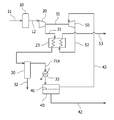
図1に示すように、本実施の形態である天然ガスからCO2を分離するシステムは、CO2およびH2Sを含有する天然ガスからH2Sを除去するH2S除去器10と、このH2S除去器でH2Sを除去した天然ガスを昇圧する圧縮機20と、この圧縮機20で昇圧した天然ガスからCO2を分離するCO2分離器40と、このCO2分離器でCO2を分離した天然ガスを、膨張させて当該天然ガスからエネルギーを回収する膨張機50とを主に備える。
H2S除去器10には、原料ガスであるCO2およびH2Sを含有する天然ガスを本システムに供給する原料ガス供給ライン11を設ける。H2S除去器10としては、特に限定されないが、吸着法や吸収法などを用いてガス中のH2Sを除去する装置が好ましい。原料ガスとしての天然ガスは、産地等によって異なるが、H2Sを%オーダーで含有するものもある。H2S除去器10は、このH2S濃度を0.5ppm以下までに除去する性能のものが好ましい。
H2S除去器10と圧縮機20は、H2Sが除去された天然ガスが流れるライン12で接続する。圧縮機20は、詳しくは後述する膨張機50と駆動軸51を共有しており、膨張機50で得られた回転エネルギーの一部を圧縮機20の駆動に用いる構成となっている。また、圧縮機20は、対象ガスをパイプライン受入圧力(例えば、4MPaG以上)にまで昇圧することができる性能を有することが好ましい。
圧縮機20とCO2分離器40は、昇圧された天然ガスが流れるライン21で接続する。このライン21に、本実施の形態では、天然ガスを冷却する冷却器22と、この冷却によって生じた凝縮液を天然ガスから除去する気液分離器30を配置する。
冷却器22は、特に限定されないが、例えば、圧縮機20で昇圧された天然ガスと冷却液を熱交換する構成を有する。冷却液としては、特に限定されないが、水などを用いることが好ましい。気液分離器30は、原料ガス中に含まれる水分および天然ガスの主成分であるメタンよりも高い沸点を有する成分(C2以上の炭化水素)の凝縮液をガスから分離できる構成を有するものであれば、特に限定されない。気液分離器30には、凝縮液を系外に排出するライン32と、凝縮液を分離した天然ガスをCO2分離器40に送るライン21aを設ける。
CO2分離器40は、CO2/CH4の選択性に優れた分離膜41を備える。分離膜41としては、例えば、規則的な細孔を有するゼオライト膜や炭素膜などの無機膜が好ましい。
CO2分離器40には、分離膜41を通過することによって天然ガスから分離されたCO2ガスが流れるライン42を設ける。また、CO2分離器40と膨張機50を、分離膜41を通過しなかった天然ガス、すなわち、CO2が除去された天然ガスが流れるライン43で接続する。
膨張機50は、高圧の天然ガスを膨張させて、例えば、タービン翼を回転させる等して、回転力としてエネルギーを取り出すことができるものであれば、特に限定されるものではない。この回転力の一部は、駆動軸51を介して圧縮機20の駆動に利用するように構成されている。また、この回転力の一部は、発電機(図示省略)の駆動にも利用することができ、電力を得ることもできる。膨張機50には、製品ガスとして、CO2及びH2Sが除去され且つ減圧された天然ガスが流れるライン52を設ける。
このような構成によれば、先ず、原料ガスであるCO2およびH2Sを含有する天然ガスが、ライン11を介してH2S除去器10に供給する。H2S除去器10では、H2S濃度を好ましくは0.5ppm以下にまで除去する。H2Sが除去された天然ガスは、ライン12を介して圧縮機20に供給する。
圧縮機20では、天然ガスの圧力を好ましくは約4~20MPaGの範囲、より好ましくは約4~10MPaGの範囲にまで昇圧する。昇圧された天然ガスは、ライン21を介してCO2分離器40に供給するが、CO2分離器40に供給する前に、冷却器22で冷却して天然ガス中の水分および高沸点成分(C2以上の炭化水素)を凝縮し、気液分離器30でこの凝縮液を天然ガスから分離する。冷却器22での冷却温度は、ガスの圧力および組成によって異なるが、ガス中の水分および高沸点成分が凝縮するように冷却する。
CO2分離器40では、分離膜41を通過するCO2ガスと、分離膜41を通過しないメタンを主成分とする天然ガスとに分離する。この時、CO2分離器40に供給される天然ガスは昇圧されていることから、分離膜41を介してCO2の分圧差が拡大されており、よって、分離膜の面積に対するガス透過量を向上させることができる。換言すれば、所定のガス透過量に対して必要な分離膜の面積を低減することができるので、高価な分離膜の設備コストを低減することができる。
また、CO2分離器40に供給される天然ガスは、H2Sが除去されているので、分離膜41にH2Sが凝縮、滞留して分離膜41を劣化させることを防ぐことができる。更に、CO2分離器40に供給される天然ガスは、水分および高沸点成分(C2以上の炭化水素)が除去されているので、分離膜41に水分および高沸点成分が凝縮して分離膜41を閉塞することを防ぐことができる。
CO2分離器40でCO2が除去された天然ガスは、ライン43を介して膨張機50に供給する。膨張機50では、供給された天然ガスの圧力を、製品ガスとしての受入圧力となるまで膨張させ、回転力としてエネルギーを取り出す。この回転力の一部は、駆動軸51を介して圧縮機20を駆動することで、圧縮機20の運転コストを低減することができる。このように圧縮機20の運転コストを低減できるので、従来のCO2吸収法および膜分離法に比べて、運転コストを大幅に改善することができる。減圧された天然ガスは、ライン52を介して製品ガスとして提供する。
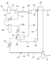
図2に示す実施の形態について説明する。なお、図1に示す実施の形態と同様の構成については同じ符号を付し、その構成および作用についての説明は省略する。
本実施の形態では、図1に示す冷却器22を、熱交換器23とした。この熱交換器23は、圧縮機20で昇圧した天然ガスと、膨張機50で減圧させた天然ガスとの間で熱交換する構成を有する。また、気液分離器30とCO2分離器40との間のライン21aには、天然ガスを加熱するための加熱器33を設ける。
このような構成によれば、熱交換器23には、圧縮機20で昇圧された天然ガスを供給するとともに、膨張機50で減圧された天然ガスを供給することから、ライン52の減圧された天然ガスの冷熱を利用して、ライン21の天然ガスを図1の冷却器22と同様に冷却し、ガス中の水分および高沸点成分(C2以上の炭化水素)を凝縮することができる。これによって、天然ガス中の水分および高沸点成分を凝縮するための冷却動力を削減することができ、更なる運転コストの低減を図ることができる。熱交換器23で冷熱が利用された天然ガスは、ライン53を介して製品ガスとして提供する。
また、本実施の形態では、気液分離器30で水分および高沸点成分の凝縮液を天然ガスから除去した後、この天然ガスを加熱器33で加熱する。天然ガスの温度は、好ましくは約20~200℃の範囲、より好ましくは約30~100℃の範囲にまで加熱することが好ましい。このようにCO2分離器40前に天然ガスを加熱しておくことで、分離性能を十分に発揮できるだけでなく、膨張機50で天然ガスを減圧する際に膨張機50内及び熱交換器23で液滴が固化して膨張機50や熱交換器23を損傷するのを防止することができる。
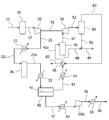
図3に示す実施の形態について説明する。なお、図1に示す実施の形態と同様の構成については同じ符号を付し、その構成および作用についての説明は省略する。
本実施の形態のシステムは、図1に示す構成に加えて、CO2分離器40で分離したCO2ガスを昇圧するCO2用圧縮機60と、この昇圧したCO2ガスを冷却して液化するCO2用冷却器62と、この液化したCO2中の含まれるオフガスを分離するCO2用気液分離器70とを更に備えるものである。
また、図1に示す気液分離器30を、天然ガス中に含まれる水分を吸着する吸着器36とした。吸着器36は、モレキュラーシーブやシリカゲル等の天然ガスから水分を吸収、除去できる吸着剤が充填されている。このような吸着器36を配置することで、原料ガスである天然ガス中の高沸点成分の濃度が高くない場合には、CO2分離器40の分離膜41でCO2が除去されても高沸点成分の分圧が蒸気圧以上に上昇しないので、分離膜41での凝縮、液化が発生することを十分に防ぐことができる。
CO2用圧縮機60とCO2用冷却器62は、CO2用圧縮機60で昇圧されたCO2ガスが流れるライン61で接続する。CO2用圧縮機60は、冷却後にCO2ガスが液化可能な圧力にまで昇圧できる性能を有するものが好ましい。また、CO2用冷却器62には、昇圧されたCO2ガスとの熱交換を行う冷熱源を供給するために、膨張機50で減圧された天然ガスが流れるライン52を接続する。
CO2用気液分離器70には、CO2用冷却器62で冷却されたCO2を供給するライン63と、CO2用気液分離器70で分離した液化CO2を排出するライン71と、CO2用気液分離器70で分離したオフガスを排出するライン72を設ける。このライン72は、オフガスをCO2分離器40のスイープガスとして再利用するためにCO2分離器40へと接続する。また、このライン72には、バルブ73を設け、オフガスを燃料等などに再利用するために系外に提供するライン74も設けることができる。さらに、ライン72には、オフガスをスイープガスとして再利用する場合に、オフガスを加熱するための加熱器75を設ける。
このような構成によれば、CO2分離器40で分離されたCO2ガスは、ライン42を介してCO2用圧縮機60に供給し、冷却後に液化可能な圧力まで昇圧する。そして、この昇圧されたCO2ガスは、ライン61を介してCO2用冷却器62に供給し、膨張機50で減圧された天然ガスの冷熱によって、臨界温度以下の温度まで冷却して液化を行う。液化CO2は、ライン63を介してCO2用気液分離器70に供給し、メタン等のオフガスを分離する。オフガスを分離した液化CO2は、例えば、ポンプ昇圧し、油田などの地中への貯留(CCS)や石油回収増進法(EOR)用のCO2として用いることができる。
一方、オフガスは、ボイラ等の燃料として使用することができる。また、オフガスは、CO2分離器40に供給してスイープガスとしても利用することができる。このようにメタンを主成分とするオフガスをスイープガスとして用いることで、分離膜の面積当たりのガス透過量を向上させることができるので、CO2分離器40に設ける分離膜41の面積を減らして、分離膜の設置コストを低減することができる。
図4に示す実施の形態について説明する。なお、図1に示す実施の形態と同様の構成については同じ符号を付し、その構成および作用についての説明は省略する。
本実施の形態のシステムは、図1に示す構成に加えて、CO2分離器40で分離したCO2ガスを昇圧するCO2用圧縮機60aと、CO2分離器40でCO2を分離した天然ガスを冷却して天然ガス中に残る高沸点成分(C2以上の炭化水素)を液化する高沸点成分用冷却器44と、高沸点成分用熱交換器45と、この高沸点成分用の冷却器、熱交換器44、45で冷却した天然ガスから液化分を分離する第一の高沸点成分用気液分離器46と、膨張機50で減圧した天然ガスから液化分を分離する第二の高沸点成分用気液分離器80とを更に備えるものである。
ここでのCO2用圧縮機60aは、CO2分離器40で分離したCO2ガスを昇圧して、製品ガスとしてCO2パイプライン等に供給するためのものである。そのため、CO2用圧縮機60aの前後には、CO2ガスを冷却する第一のCO2用冷却器64および第二のCO2用冷却器65を配置する。CO2用圧縮機60aと第一および第二のCO2用冷却器64、65は、CO2ガスの圧力をCO2パイプライン受入圧力以上に昇圧する性能を有するものである。
高沸点成分用の冷却器、熱交換器44、45は、CO2分離器40でCO2を分離した天然ガス中に残る高沸点成分が液化する温度まで冷却する性能を有するものであることが好ましい。第一の高沸点成分用気液分離器46には、液化した高沸点成分を製品として提供するためのライン48と、この液化分を除去した天然ガスを膨張機50に供給するライン47を設ける。第二の高沸点成分用気液分離器80には、液化した高沸点成分を製品として提供するためのライン81と、この液化分を除去した天然ガスを高沸点成分用熱交換器45の冷熱源として供給するライン82を設ける。
このような構成によれば、CO2分離器40で分離されたCO2ガスは、ライン42を介してCO2用圧縮機60a並びに第一および第二のCO2用冷却器64、65で、CO2パイプライン受入圧力、温度にまで昇圧、冷却する。そして、このように昇圧、冷却されたCO2ガスは、ライン66を介して製品として提供する。
また、CO2分離器40でCO2が分離された天然ガスは、ライン43を介して高沸点成分用の冷却器、熱交換器44、45に順に供給して冷却し、天然ガス中に残る高沸点成分を液化する。そして、第一の高沸点成分用気液分離器46で、液化した高沸点成分を分離して、ライン48を介して提供する。
一方、この液化分を除去した天然ガスは、ライン47を介して膨張機50に供給する。膨張機50では、この天然ガスをパイプライン受入圧力にまで減圧する。ガス中に残る高沸点成分が液化するため、第二の高沸点成分用気液分離器80で、液化した高沸点成分を分離して、ライン81を介して製品として提供する。また、この液化分を除去した天然ガスは、ライン82を介して高沸点成分用熱交換器45に冷熱源として供給する。冷熱源として使用された天然ガスは、ライン83を介して製品ガスとして提供される。
CO2分離器40後流の天然ガス中に含まれる高価な高沸点成分を得るために、本実施の形態では、CO2分離器40の後に、天然ガスを冷却したり、膨張させ、これにより、CO2を含まない高沸点成分の液体を得ることができる。
10 H2S除去器
20、60 圧縮機
22、44、64、65 冷却器
23、45、62 熱交換器
30、46、70、80 気液分離器
33、75 加熱器
36 吸着器
40 CO2分離器
41 分離膜
50 膨張機
51 駆動軸
20、60 圧縮機
22、44、64、65 冷却器
23、45、62 熱交換器
30、46、70、80 気液分離器
33、75 加熱器
36 吸着器
40 CO2分離器
41 分離膜
50 膨張機
51 駆動軸
Claims (8)
- 二酸化炭素および硫化水素を含有する天然ガスから二酸化炭素を分離するシステムであって、
前記天然ガスから硫化水素を除去する硫化水素除去器と、
前記硫化水素除去器で硫化水素を除去した天然ガスを昇圧する圧縮機と、
前記圧縮機で昇圧した天然ガスを冷却し、ガスの一部を凝縮する冷却器と、
前記冷却器で冷却した天然ガス中の凝縮成分を除去する気液分離器と、
前記気液分離器で凝縮成分を除去した天然ガスから二酸化炭素を分離する分離膜を備える二酸化炭素分離器と、
前記二酸化炭素分離器で二酸化炭素を分離した天然ガスを、膨張させて当該天然ガスからエネルギーを回収する膨張機と
を備えるシステム。 - 前記冷却器が、前記圧縮機で昇圧した天然ガスと、前記膨張機で膨張させた天然ガスとの間で熱交換する熱交換器である請求項1に記載のシステム。
- 前記二酸化炭素分離器で分離した二酸化炭素を含有するガスを昇圧する第二の圧縮機と、前記第二の圧縮機で昇圧した二酸化炭素を含有するガスを冷却して液化する第二の熱交換器と、この液化物に含まれるオフガスを分離する第二の気液分離器と、前記膨張機で膨張させた天然ガスを前記第二の熱交換器の冷熱源として供給するラインとを更に備える請求項1に記載のシステム。
- 前記二酸化炭素分離器で二酸化炭素を分離した天然ガスを冷却し、ガスの一部を液化する第三の熱交換器と、前記第三の冷却器で冷却した天然ガスから液化分を分離する第三の気液分離器と、前記第三の気液分離器で液化分を分離した天然ガスを前記膨張機に供給するラインと、前記膨張機で膨張させた天然ガスを前記第三の熱交換器の冷熱源として供給するラインとを更に備える請求項1に記載のシステム。
- 二酸化炭素および硫化水素を含有する天然ガスから二酸化炭素を分離する方法であって、
前記天然ガスから硫化水素を除去するステップと、
前記硫化水素を除去した天然ガスを圧縮して昇圧するステップと、
前記昇圧した天然ガスを冷却し、ガスの一部を凝縮するステップと、
前記冷却した天然ガス中の凝縮成分を除去するステップと、
分離膜を用いて、前記凝縮成分が除去された天然ガスから二酸化炭素を分離するステップと、
前記二酸化炭素が除去された天然ガスを膨張させて、当該天然ガスからエネルギーを回収するステップと
を含む方法。 - 前記昇圧した天然ガスを冷却するステップが、前記昇圧した天然ガスと、前記膨張させた天然ガスとの間で熱交換することで行う請求項5に記載の方法。
- 前記分離膜を用いて分離した二酸化炭素を含有するガスを昇圧するステップと、前記昇圧した二酸化炭素を含有するガスを冷却して液化する第二の冷却ステップと、この液化物に含まれるオフガスを液化物から分離する第二の気液分離ステップとを更に含み、前記二酸化炭素を含有するガスを冷却する第二の冷却ステップが、前記二酸化炭素を含有するガスと、前記膨張させた天然ガスとの間で熱交換することで行う請求項5に記載の方法。
- 前記分離膜を用いて二酸化炭素を分離した天然ガスを冷却し、ガスの一部を液化する第三の冷却ステップと、前記第三の冷却ステップで冷却した天然ガスから液化分を分離する第三の気液分離ステップとを更に含み、前記天然ガスを膨張させるステップが、前記第三の気液分離ステップで液化分を分離した天然ガスを膨張させるものであり、
前記第三の冷却ステップが、前記二酸化炭素を分離した天然ガスと、前記膨張させた天然ガスとの間で熱交換することで行う請求項5に記載の方法。
Priority Applications (2)
| Application Number | Priority Date | Filing Date | Title |
|---|---|---|---|
| US15/553,293 US10315157B2 (en) | 2015-02-26 | 2015-11-16 | System and method for separating carbon dioxide from natural gas |
| CA2977195A CA2977195C (en) | 2015-02-26 | 2015-11-16 | System and method for separating carbon dioxide from natural gas |
Applications Claiming Priority (2)
| Application Number | Priority Date | Filing Date | Title |
|---|---|---|---|
| JP2015-036710 | 2015-02-26 | ||
| JP2015036710A JP6199918B2 (ja) | 2015-02-26 | 2015-02-26 | 天然ガスから二酸化炭素を分離するシステム及び方法 |
Publications (1)
| Publication Number | Publication Date |
|---|---|
| WO2016136046A1 true WO2016136046A1 (ja) | 2016-09-01 |
Family
ID=56788233
Family Applications (1)
| Application Number | Title | Priority Date | Filing Date |
|---|---|---|---|
| PCT/JP2015/082071 Ceased WO2016136046A1 (ja) | 2015-02-26 | 2015-11-16 | 天然ガスから二酸化炭素を分離するシステム及び方法 |
Country Status (4)
| Country | Link |
|---|---|
| US (1) | US10315157B2 (ja) |
| JP (1) | JP6199918B2 (ja) |
| CA (1) | CA2977195C (ja) |
| WO (1) | WO2016136046A1 (ja) |
Families Citing this family (27)
| Publication number | Priority date | Publication date | Assignee | Title |
|---|---|---|---|---|
| KR101906917B1 (ko) | 2017-01-13 | 2018-10-11 | 한양대학교 산학협력단 | 가스 혼합물로부터 이산화탄소의 포획 및 분리를 위한 분리막 기반 공정 |
| JP6764798B2 (ja) * | 2017-01-30 | 2020-10-07 | 三菱重工業株式会社 | プラント及びプラントの運転方法 |
| US10336956B2 (en) | 2017-03-31 | 2019-07-02 | Mitsubishi Heavy Industries, Ltd. | Natural-gas purification apparatus |
| US10179310B2 (en) | 2017-03-31 | 2019-01-15 | Mitsubishi Heavy Industries, Ltd. | Natural-gas purification apparatus |
| US10118129B2 (en) | 2017-03-31 | 2018-11-06 | Mitsubishi Heavy Industries, Ltd. | Natural-gas purification apparatus |
| US10293300B2 (en) | 2017-03-31 | 2019-05-21 | Mitsubishi Heavy Industries, Ltd. | Natural-gas purification apparatus |
| US10246660B2 (en) | 2017-03-31 | 2019-04-02 | Mitsubishi Heavy Industries, Ltd. | Natural-gas purification apparatus |
| FR3069458B1 (fr) * | 2017-07-27 | 2019-08-02 | L'air Liquide, Societe Anonyme Pour L'etude Et L'exploitation Des Procedes Georges Claude | Procede de purification d'un courant de gaz naturel |
| FR3069456B1 (fr) * | 2017-07-27 | 2022-02-18 | Air Liquide | Methode de purification de gaz naturel mettant en œuvre un economiseur. |
| FR3069457B1 (fr) * | 2017-07-27 | 2019-08-02 | L'air Liquide, Societe Anonyme Pour L'etude Et L'exploitation Des Procedes Georges Claude | Procede de separation d'un courant de gaz naturel en une fraction enrichie en methane et une fraction enrichie en hydrocarbures en c2 et superieurs |
| WO2019230995A1 (ko) * | 2018-05-28 | 2019-12-05 | 한양대학교 산학협력단 | 가스 혼합물로부터 이산화탄소의 포획 및 분리를 위한 분리막 기반 공정 |
| MY188660A (en) * | 2018-06-18 | 2021-12-22 | Japan Oil Gas & Metals Jogmec | Acidic gas separation device and acidic gas separation method |
| JP7532871B2 (ja) * | 2019-04-26 | 2024-08-14 | 三菱ケミカル株式会社 | ガスの製造方法、および、二酸化炭素の分離システム |
| CN111649539A (zh) * | 2020-05-06 | 2020-09-11 | 天津凯德实业有限公司 | 富含二氧化碳油气井天然气脱碳并回收二氧化碳和液化装置及其工艺 |
| JP7407351B2 (ja) * | 2021-01-07 | 2024-01-04 | パナソニックIpマネジメント株式会社 | 二酸化炭素分離回収装置 |
| CN114788983B (zh) * | 2021-01-26 | 2023-09-08 | 大连佳纯气体净化技术开发有限公司 | 一种低温甲醇洗净化方法及装置 |
| CN115463524A (zh) * | 2021-06-10 | 2022-12-13 | 中石化南京化工研究院有限公司 | 一种膜分离节能装置和方法及其应用 |
| JP7739824B2 (ja) * | 2021-08-04 | 2025-09-17 | 富士電機株式会社 | ガス処理システム |
| EP4186583A1 (en) * | 2021-11-24 | 2023-05-31 | Linde GmbH | Method and arrangement for separating carbon dioxide from a feed stream containing carbon dioxide |
| CN116410800B (zh) * | 2021-12-29 | 2025-11-14 | 中国石油天然气股份有限公司 | 一种天然气脱硫装置及节能方法 |
| JP2023170040A (ja) * | 2022-05-18 | 2023-12-01 | 富士電機株式会社 | ガス処理システム |
| WO2024013957A1 (ja) * | 2022-07-15 | 2024-01-18 | 三菱電機株式会社 | 二酸化炭素回収システム |
| KR102808038B1 (ko) * | 2022-10-07 | 2025-05-16 | 에이치디한국조선해양 주식회사 | 이산화탄소 처리 시스템 및 이를 포함하는 구조물 |
| CN116003197A (zh) * | 2023-01-18 | 2023-04-25 | 中海石油气电集团有限责任公司 | 一种利用海上风电实现二氧化碳制备甲烷的方法 |
| CN116556909B (zh) * | 2023-04-19 | 2024-05-28 | 中国石油天然气股份有限公司 | 一种二氧化碳驱高效分离及循环回注利用装置及方法 |
| CN117185387B (zh) * | 2023-09-11 | 2026-02-17 | 山东京博众诚清洁能源有限公司 | 一种利用meda废液再生硫化氢和二氧化碳的系统和方法 |
| JP2025082900A (ja) * | 2023-11-20 | 2025-05-30 | 三菱重工業株式会社 | 二酸化炭素回収システム及び二酸化炭素回収方法 |
Citations (3)
| Publication number | Priority date | Publication date | Assignee | Title |
|---|---|---|---|---|
| JP2006507385A (ja) * | 2002-11-21 | 2006-03-02 | レール・リキード−ソシエテ・アノニム・ア・ディレクトワール・エ・コンセイユ・ドゥ・スールベイランス・プール・レテュード・エ・レクスプロワタシオン・デ・プロセデ・ジョルジュ・クロード | 膜分離プロセス |
| WO2013086194A1 (en) * | 2011-12-06 | 2013-06-13 | Cameron International Corporation | Floating liquefied natural gas pretreatment system |
| JP2013534863A (ja) * | 2010-07-01 | 2013-09-09 | エボニック ファイバース ゲゼルシャフト ミット ベシュレンクテル ハフツング | ガス分離法 |
Family Cites Families (15)
| Publication number | Priority date | Publication date | Assignee | Title |
|---|---|---|---|---|
| ATE428486T1 (de) * | 2003-09-09 | 2009-05-15 | Fluor Corp | Verbesserte lösungsmittelverwendung und regenration |
| JP4585222B2 (ja) | 2004-04-12 | 2010-11-24 | 三菱重工業株式会社 | 不純物廃棄システム及び方法 |
| US20060191410A1 (en) * | 2005-02-28 | 2006-08-31 | Dolan William B | NGL trap-method for recovery of heavy hydrocarbon from natural gas |
| US20080011161A1 (en) | 2006-07-17 | 2008-01-17 | General Electric Company | Carbon dioxide capture systems and methods |
| US20080127632A1 (en) | 2006-11-30 | 2008-06-05 | General Electric Company | Carbon dioxide capture systems and methods |
| US9752826B2 (en) * | 2007-05-18 | 2017-09-05 | Pilot Energy Solutions, Llc | NGL recovery from a recycle stream having natural gas |
| RU2533260C2 (ru) * | 2009-06-12 | 2014-11-20 | Шелл Интернэшнл Рисерч Маатсхаппий Б.В. | Способ для очистки от кислых соединений и сжижения газообразного потока и устройство для его осуществления |
| US20110142722A1 (en) * | 2009-12-14 | 2011-06-16 | John William Hemmings | Method and apparatus for producing synthesis gas |
| US9051228B2 (en) * | 2013-05-31 | 2015-06-09 | Guild Associates | LNG pretreatment |
| US9964034B2 (en) * | 2014-04-09 | 2018-05-08 | Exxonmobil Upstream Research Company | Methods for producing a fuel gas stream |
| US11173445B2 (en) * | 2015-09-16 | 2021-11-16 | 1304338 Alberta Ltd. | Method of preparing natural gas at a gas pressure reduction stations to produce liquid natural gas (LNG) |
| US9969949B1 (en) * | 2016-10-20 | 2018-05-15 | Iogen Corporation | Method and system for providing upgraded biogas |
| US9943802B1 (en) * | 2017-03-13 | 2018-04-17 | Saudi Arabian Oil Company | Enhancement of claus tail gas treatment with membrane and reducing step |
| WO2019040305A1 (en) * | 2017-08-21 | 2019-02-28 | Exxonmobil Upstream Research Company | INTEGRATION OF COLD SOLVENT AND REMOVAL OF ACIDIC GAS |
| CA3073038C (en) * | 2017-08-21 | 2023-02-14 | Exxonmobil Upstream Research Company | Integration of cold solvent and acid gas removal |
-
2015
- 2015-02-26 JP JP2015036710A patent/JP6199918B2/ja not_active Expired - Fee Related
- 2015-11-16 WO PCT/JP2015/082071 patent/WO2016136046A1/ja not_active Ceased
- 2015-11-16 CA CA2977195A patent/CA2977195C/en not_active Expired - Fee Related
- 2015-11-16 US US15/553,293 patent/US10315157B2/en not_active Expired - Fee Related
Patent Citations (3)
| Publication number | Priority date | Publication date | Assignee | Title |
|---|---|---|---|---|
| JP2006507385A (ja) * | 2002-11-21 | 2006-03-02 | レール・リキード−ソシエテ・アノニム・ア・ディレクトワール・エ・コンセイユ・ドゥ・スールベイランス・プール・レテュード・エ・レクスプロワタシオン・デ・プロセデ・ジョルジュ・クロード | 膜分離プロセス |
| JP2013534863A (ja) * | 2010-07-01 | 2013-09-09 | エボニック ファイバース ゲゼルシャフト ミット ベシュレンクテル ハフツング | ガス分離法 |
| WO2013086194A1 (en) * | 2011-12-06 | 2013-06-13 | Cameron International Corporation | Floating liquefied natural gas pretreatment system |
Also Published As
| Publication number | Publication date |
|---|---|
| US10315157B2 (en) | 2019-06-11 |
| JP2016155987A (ja) | 2016-09-01 |
| US20180028965A1 (en) | 2018-02-01 |
| CA2977195C (en) | 2019-04-16 |
| JP6199918B2 (ja) | 2017-09-20 |
| CA2977195A1 (en) | 2016-09-01 |
Similar Documents
| Publication | Publication Date | Title |
|---|---|---|
| JP6199918B2 (ja) | 天然ガスから二酸化炭素を分離するシステム及び方法 | |
| JP5566448B2 (ja) | 高圧酸性ガスを除去するための改良された構成および方法 | |
| CN102238994B (zh) | 移除高压酸性气体的装置和方法 | |
| US8876951B2 (en) | Gas purification configurations and methods | |
| JP4673624B2 (ja) | 酸性ガスを除去するための構成および方法 | |
| JP4771663B2 (ja) | 改良された酸性ガス除去のための構成および方法 | |
| JP4105697B2 (ja) | 酸性ガス除去プラントおよび方法 | |
| US9776124B2 (en) | Configurations and methods of high pressure acid gas removal in the production of ultra-low sulfur gas | |
| JP2006509622A5 (ja) | ||
| JP2005538841A5 (ja) | ||
| WO2018013099A1 (en) | Heavy hydrocarbon removal from lean gas to lng liquefaction | |
| GB2540468A (en) | Method and apparatus for dehydration of a hydrocarbon gas | |
| CN101970079B (zh) | 再生器构造和具有降低的蒸汽需求的方法 | |
| US10393015B2 (en) | Methods and systems for treating fuel gas | |
| US20120297822A1 (en) | Separation of gases | |
| JP6940206B2 (ja) | 酸性ガス分離装置 | |
| CN107278167B (zh) | 一种以减少的汽提蒸汽供给从吸收剂中回收二氧化碳的方法 | |
| JP2005290151A (ja) | ガスの製造方法 | |
| AU2024204337B2 (en) | Acidic gas recovery apparatus and acidic gas recovery method | |
| AU2007201677A1 (en) | Configurations and methods for improved acid gas removal |
Legal Events
| Date | Code | Title | Description |
|---|---|---|---|
| 121 | Ep: the epo has been informed by wipo that ep was designated in this application |
Ref document number: 15883336 Country of ref document: EP Kind code of ref document: A1 |
|
| ENP | Entry into the national phase |
Ref document number: 2977195 Country of ref document: CA |
|
| NENP | Non-entry into the national phase |
Ref country code: DE |
|
| 122 | Ep: pct application non-entry in european phase |
Ref document number: 15883336 Country of ref document: EP Kind code of ref document: A1 |