WO2016135958A1 - Motor control method and control device, and machine tool provided with tool magazine - Google Patents
Motor control method and control device, and machine tool provided with tool magazine Download PDFInfo
- Publication number
- WO2016135958A1 WO2016135958A1 PCT/JP2015/055899 JP2015055899W WO2016135958A1 WO 2016135958 A1 WO2016135958 A1 WO 2016135958A1 JP 2015055899 W JP2015055899 W JP 2015055899W WO 2016135958 A1 WO2016135958 A1 WO 2016135958A1
- Authority
- WO
- WIPO (PCT)
- Prior art keywords
- torque
- unbalance
- rotary shaft
- tool
- tool magazine
- Prior art date
Links
Images


Classifications
-
- G—PHYSICS
- G05—CONTROLLING; REGULATING
- G05B—CONTROL OR REGULATING SYSTEMS IN GENERAL; FUNCTIONAL ELEMENTS OF SUCH SYSTEMS; MONITORING OR TESTING ARRANGEMENTS FOR SUCH SYSTEMS OR ELEMENTS
- G05B19/00—Programme-control systems
- G05B19/02—Programme-control systems electric
- G05B19/18—Numerical control [NC], i.e. automatically operating machines, in particular machine tools, e.g. in a manufacturing environment, so as to execute positioning, movement or co-ordinated operations by means of programme data in numerical form
- G05B19/402—Numerical control [NC], i.e. automatically operating machines, in particular machine tools, e.g. in a manufacturing environment, so as to execute positioning, movement or co-ordinated operations by means of programme data in numerical form characterised by control arrangements for positioning, e.g. centring a tool relative to a hole in the workpiece, additional detection means to correct position
-
- B—PERFORMING OPERATIONS; TRANSPORTING
- B23—MACHINE TOOLS; METAL-WORKING NOT OTHERWISE PROVIDED FOR
- B23Q—DETAILS, COMPONENTS, OR ACCESSORIES FOR MACHINE TOOLS, e.g. ARRANGEMENTS FOR COPYING OR CONTROLLING; MACHINE TOOLS IN GENERAL CHARACTERISED BY THE CONSTRUCTION OF PARTICULAR DETAILS OR COMPONENTS; COMBINATIONS OR ASSOCIATIONS OF METAL-WORKING MACHINES, NOT DIRECTED TO A PARTICULAR RESULT
- B23Q11/00—Accessories fitted to machine tools for keeping tools or parts of the machine in good working condition or for cooling work; Safety devices specially combined with or arranged in, or specially adapted for use in connection with, machine tools
- B23Q11/001—Arrangements compensating weight or flexion on parts of the machine
- B23Q11/0028—Arrangements compensating weight or flexion on parts of the machine by actively reacting to a change of the configuration of the machine
-
- B—PERFORMING OPERATIONS; TRANSPORTING
- B23—MACHINE TOOLS; METAL-WORKING NOT OTHERWISE PROVIDED FOR
- B23Q—DETAILS, COMPONENTS, OR ACCESSORIES FOR MACHINE TOOLS, e.g. ARRANGEMENTS FOR COPYING OR CONTROLLING; MACHINE TOOLS IN GENERAL CHARACTERISED BY THE CONSTRUCTION OF PARTICULAR DETAILS OR COMPONENTS; COMBINATIONS OR ASSOCIATIONS OF METAL-WORKING MACHINES, NOT DIRECTED TO A PARTICULAR RESULT
- B23Q11/00—Accessories fitted to machine tools for keeping tools or parts of the machine in good working condition or for cooling work; Safety devices specially combined with or arranged in, or specially adapted for use in connection with, machine tools
- B23Q11/08—Protective coverings for parts of machine tools; Splash guards
- B23Q11/0891—Protective coverings for parts of machine tools; Splash guards arranged between the working area and the operator
-
- B—PERFORMING OPERATIONS; TRANSPORTING
- B23—MACHINE TOOLS; METAL-WORKING NOT OTHERWISE PROVIDED FOR
- B23Q—DETAILS, COMPONENTS, OR ACCESSORIES FOR MACHINE TOOLS, e.g. ARRANGEMENTS FOR COPYING OR CONTROLLING; MACHINE TOOLS IN GENERAL CHARACTERISED BY THE CONSTRUCTION OF PARTICULAR DETAILS OR COMPONENTS; COMBINATIONS OR ASSOCIATIONS OF METAL-WORKING MACHINES, NOT DIRECTED TO A PARTICULAR RESULT
- B23Q16/00—Equipment for precise positioning of tool or work into particular locations not otherwise provided for
- B23Q16/02—Indexing equipment
-
- B—PERFORMING OPERATIONS; TRANSPORTING
- B23—MACHINE TOOLS; METAL-WORKING NOT OTHERWISE PROVIDED FOR
- B23Q—DETAILS, COMPONENTS, OR ACCESSORIES FOR MACHINE TOOLS, e.g. ARRANGEMENTS FOR COPYING OR CONTROLLING; MACHINE TOOLS IN GENERAL CHARACTERISED BY THE CONSTRUCTION OF PARTICULAR DETAILS OR COMPONENTS; COMBINATIONS OR ASSOCIATIONS OF METAL-WORKING MACHINES, NOT DIRECTED TO A PARTICULAR RESULT
- B23Q17/00—Arrangements for observing, indicating or measuring on machine tools
- B23Q17/22—Arrangements for observing, indicating or measuring on machine tools for indicating or measuring existing or desired position of tool or work
-
- B—PERFORMING OPERATIONS; TRANSPORTING
- B23—MACHINE TOOLS; METAL-WORKING NOT OTHERWISE PROVIDED FOR
- B23Q—DETAILS, COMPONENTS, OR ACCESSORIES FOR MACHINE TOOLS, e.g. ARRANGEMENTS FOR COPYING OR CONTROLLING; MACHINE TOOLS IN GENERAL CHARACTERISED BY THE CONSTRUCTION OF PARTICULAR DETAILS OR COMPONENTS; COMBINATIONS OR ASSOCIATIONS OF METAL-WORKING MACHINES, NOT DIRECTED TO A PARTICULAR RESULT
- B23Q3/00—Devices holding, supporting, or positioning work or tools, of a kind normally removable from the machine
- B23Q3/155—Arrangements for automatic insertion or removal of tools, e.g. combined with manual handling
- B23Q3/1552—Arrangements for automatic insertion or removal of tools, e.g. combined with manual handling parts of devices for automatically inserting or removing tools
- B23Q3/15526—Storage devices; Drive mechanisms therefor
-
- B—PERFORMING OPERATIONS; TRANSPORTING
- B23—MACHINE TOOLS; METAL-WORKING NOT OTHERWISE PROVIDED FOR
- B23Q—DETAILS, COMPONENTS, OR ACCESSORIES FOR MACHINE TOOLS, e.g. ARRANGEMENTS FOR COPYING OR CONTROLLING; MACHINE TOOLS IN GENERAL CHARACTERISED BY THE CONSTRUCTION OF PARTICULAR DETAILS OR COMPONENTS; COMBINATIONS OR ASSOCIATIONS OF METAL-WORKING MACHINES, NOT DIRECTED TO A PARTICULAR RESULT
- B23Q3/00—Devices holding, supporting, or positioning work or tools, of a kind normally removable from the machine
- B23Q3/155—Arrangements for automatic insertion or removal of tools, e.g. combined with manual handling
- B23Q3/157—Arrangements for automatic insertion or removal of tools, e.g. combined with manual handling of rotary tools
- B23Q3/15713—Arrangements for automatic insertion or removal of tools, e.g. combined with manual handling of rotary tools a transfer device taking a single tool from a storage device and inserting it in a spindle
- B23Q3/1572—Arrangements for automatic insertion or removal of tools, e.g. combined with manual handling of rotary tools a transfer device taking a single tool from a storage device and inserting it in a spindle the storage device comprising rotating or circulating storing means
- B23Q3/15722—Rotary discs or drums
-
- B—PERFORMING OPERATIONS; TRANSPORTING
- B23—MACHINE TOOLS; METAL-WORKING NOT OTHERWISE PROVIDED FOR
- B23Q—DETAILS, COMPONENTS, OR ACCESSORIES FOR MACHINE TOOLS, e.g. ARRANGEMENTS FOR COPYING OR CONTROLLING; MACHINE TOOLS IN GENERAL CHARACTERISED BY THE CONSTRUCTION OF PARTICULAR DETAILS OR COMPONENTS; COMBINATIONS OR ASSOCIATIONS OF METAL-WORKING MACHINES, NOT DIRECTED TO A PARTICULAR RESULT
- B23Q5/00—Driving or feeding mechanisms; Control arrangements therefor
- B23Q5/22—Feeding members carrying tools or work
- B23Q5/34—Feeding other members supporting tools or work, e.g. saddles, tool-slides, through mechanical transmission
-
- G—PHYSICS
- G01—MEASURING; TESTING
- G01M—TESTING STATIC OR DYNAMIC BALANCE OF MACHINES OR STRUCTURES; TESTING OF STRUCTURES OR APPARATUS, NOT OTHERWISE PROVIDED FOR
- G01M1/00—Testing static or dynamic balance of machines or structures
- G01M1/10—Determining the moment of inertia
-
- G—PHYSICS
- G01—MEASURING; TESTING
- G01M—TESTING STATIC OR DYNAMIC BALANCE OF MACHINES OR STRUCTURES; TESTING OF STRUCTURES OR APPARATUS, NOT OTHERWISE PROVIDED FOR
- G01M1/00—Testing static or dynamic balance of machines or structures
- G01M1/14—Determining unbalance
-
- G—PHYSICS
- G01—MEASURING; TESTING
- G01M—TESTING STATIC OR DYNAMIC BALANCE OF MACHINES OR STRUCTURES; TESTING OF STRUCTURES OR APPARATUS, NOT OTHERWISE PROVIDED FOR
- G01M1/00—Testing static or dynamic balance of machines or structures
- G01M1/14—Determining unbalance
- G01M1/16—Determining unbalance by oscillating or rotating the body to be tested
- G01M1/28—Determining unbalance by oscillating or rotating the body to be tested with special adaptations for determining unbalance of the body in situ, e.g. of vehicle wheels
-
- G—PHYSICS
- G05—CONTROLLING; REGULATING
- G05B—CONTROL OR REGULATING SYSTEMS IN GENERAL; FUNCTIONAL ELEMENTS OF SUCH SYSTEMS; MONITORING OR TESTING ARRANGEMENTS FOR SUCH SYSTEMS OR ELEMENTS
- G05B19/00—Programme-control systems
- G05B19/02—Programme-control systems electric
- G05B19/18—Numerical control [NC], i.e. automatically operating machines, in particular machine tools, e.g. in a manufacturing environment, so as to execute positioning, movement or co-ordinated operations by means of programme data in numerical form
- G05B19/404—Numerical control [NC], i.e. automatically operating machines, in particular machine tools, e.g. in a manufacturing environment, so as to execute positioning, movement or co-ordinated operations by means of programme data in numerical form characterised by control arrangements for compensation, e.g. for backlash, overshoot, tool offset, tool wear, temperature, machine construction errors, load, inertia
-
- G—PHYSICS
- G05—CONTROLLING; REGULATING
- G05B—CONTROL OR REGULATING SYSTEMS IN GENERAL; FUNCTIONAL ELEMENTS OF SUCH SYSTEMS; MONITORING OR TESTING ARRANGEMENTS FOR SUCH SYSTEMS OR ELEMENTS
- G05B19/00—Programme-control systems
- G05B19/02—Programme-control systems electric
- G05B19/18—Numerical control [NC], i.e. automatically operating machines, in particular machine tools, e.g. in a manufacturing environment, so as to execute positioning, movement or co-ordinated operations by means of programme data in numerical form
- G05B19/416—Numerical control [NC], i.e. automatically operating machines, in particular machine tools, e.g. in a manufacturing environment, so as to execute positioning, movement or co-ordinated operations by means of programme data in numerical form characterised by control of velocity, acceleration or deceleration
-
- B—PERFORMING OPERATIONS; TRANSPORTING
- B23—MACHINE TOOLS; METAL-WORKING NOT OTHERWISE PROVIDED FOR
- B23Q—DETAILS, COMPONENTS, OR ACCESSORIES FOR MACHINE TOOLS, e.g. ARRANGEMENTS FOR COPYING OR CONTROLLING; MACHINE TOOLS IN GENERAL CHARACTERISED BY THE CONSTRUCTION OF PARTICULAR DETAILS OR COMPONENTS; COMBINATIONS OR ASSOCIATIONS OF METAL-WORKING MACHINES, NOT DIRECTED TO A PARTICULAR RESULT
- B23Q16/00—Equipment for precise positioning of tool or work into particular locations not otherwise provided for
- B23Q16/02—Indexing equipment
- B23Q16/022—Indexing equipment in which only the indexing movement is of importance
- B23Q16/025—Indexing equipment in which only the indexing movement is of importance by converting a continuous movement into a rotary indexing movement
-
- B—PERFORMING OPERATIONS; TRANSPORTING
- B23—MACHINE TOOLS; METAL-WORKING NOT OTHERWISE PROVIDED FOR
- B23Q—DETAILS, COMPONENTS, OR ACCESSORIES FOR MACHINE TOOLS, e.g. ARRANGEMENTS FOR COPYING OR CONTROLLING; MACHINE TOOLS IN GENERAL CHARACTERISED BY THE CONSTRUCTION OF PARTICULAR DETAILS OR COMPONENTS; COMBINATIONS OR ASSOCIATIONS OF METAL-WORKING MACHINES, NOT DIRECTED TO A PARTICULAR RESULT
- B23Q3/00—Devices holding, supporting, or positioning work or tools, of a kind normally removable from the machine
- B23Q3/155—Arrangements for automatic insertion or removal of tools, e.g. combined with manual handling
- B23Q3/157—Arrangements for automatic insertion or removal of tools, e.g. combined with manual handling of rotary tools
- B23Q3/15713—Arrangements for automatic insertion or removal of tools, e.g. combined with manual handling of rotary tools a transfer device taking a single tool from a storage device and inserting it in a spindle
-
- G—PHYSICS
- G05—CONTROLLING; REGULATING
- G05B—CONTROL OR REGULATING SYSTEMS IN GENERAL; FUNCTIONAL ELEMENTS OF SUCH SYSTEMS; MONITORING OR TESTING ARRANGEMENTS FOR SUCH SYSTEMS OR ELEMENTS
- G05B2219/00—Program-control systems
- G05B2219/30—Nc systems
- G05B2219/41—Servomotor, servo controller till figures
- G05B2219/41398—Estimate twist between motor and load, observe motor position and speed
Definitions
- a rotary table 114 provided so as to be able to rotate and feed in the B-axis direction around a vertical axis on the upper surface of the shaft slider 112, and a left-right direction or an X-axis direction (FIG. 1) on the upper surface of the rear portion (right side in FIG. 1)
- the column 104 is provided so as to be able to reciprocate along a pair of X-axis guide rails 102a extending in a direction perpendicular to the paper surface. Reciprocally disposed along the set has been Y-axis guide rails 104a (FIG.
- the acceleration / deceleration parameter changing unit 28 receives the torque 24a corrected by the unbalance torque canceling unit 24, the position received by the unbalance torque canceling unit 24 from the encoder 20, and the speed information 20c from the unbalance torque canceling unit 24, and is corrected.
- the moment of inertia of the tool magazine 120 is calculated based on the torque 24a.
- the acceleration / deceleration parameter changing unit 28 receives the inertia moment of the tool magazine 120 from the inertia moment calculating unit 26, changes (corrects) the acceleration / deceleration parameter, and outputs it to the servo control unit 16.
- the current value 16a output to is optimized. Further, when the alarm display unit 30 is provided in the control device 10 and the unbalance torque calculated by the unbalance torque calculation unit 22 is larger than a predetermined upper limit value, an acoustic or visual alarm or A warning can be displayed.
Abstract
A method for controlling the motor of a tool magazine (120) that rotates around a horizontal rotation axis (120a) is configured so that: at least two indexing positions for the tool magazine (120) are determined; the load torque acting on the tool magazine (120) when stopped at said indexing positions is measured; an unbalance torque, which is the load torque when stopped at the indexing position at which the load torque when stopped is maximal, is calculated from multiple load torques when stopped; and the servo motor (18) for the tool magazine (120) is controlled on the basis of the unbalance torque.
Description
本発明は、アンバランストルクを考慮したモータの制御方法、該方法を実行する制御装置および工具マガジンを備えた工作機械に関する。
The present invention relates to a motor control method in consideration of unbalance torque, a control device for executing the method, and a machine tool including a tool magazine.
特許文献1には、工具マガジンに装着されている工具の形状および分布から工具マガジンの慣性モーメントおよびアンバランストルクを推定し、アンバランストルクを加減した最適な加速度を決定するモータの制御方法が記載されている。
Patent Document 1 describes a motor control method for estimating the moment of inertia and unbalance torque of a tool magazine from the shape and distribution of the tool mounted on the tool magazine, and determining the optimum acceleration by adjusting the unbalance torque. Has been.
特許文献1の発明では、工具マガジンに装着されている工具の形状および分布が予め既知でなければならないので、工作機械のオペレータが工具の入れ換え作業を行ったときに、自動的にモータの加減速パラメータを変更することができない。
In the invention of Patent Document 1, since the shape and distribution of the tool mounted on the tool magazine must be known in advance, the acceleration / deceleration of the motor is automatically performed when the operator of the machine tool performs the tool replacement work. The parameter cannot be changed.
本発明は、こうした従来技術の問題を解決することを技術課題としており、不均一に配置された質量の移動により、負荷トルクが変動する回転軸装置において、アンバランストルクを確実に推定し、回転軸装置の動作時間を短縮することを目的としている。
An object of the present invention is to solve such problems of the prior art, and in a rotating shaft device in which the load torque varies due to the movement of a non-uniformly arranged mass, the unbalance torque is reliably estimated and rotated. The purpose is to shorten the operating time of the shaft device.
上述の目的を達成するために、本発明によれば、水平または傾斜した回転軸周りに回転する回転軸装置のモータの制御方法において、前記回転軸装置を少なくとも2ヶ所の割出位置に割出し、前記割出位置で、回転軸装置に作用する停止負荷トルクを測定し、複数の前記停止時負荷トルクから、停止時負荷トルクが最大となる割出位置での停止時負荷トルクであるアンバランストルクを算出し、前記アンバランストルクに基づいて回転軸装置のモータを制御するようにしたモータの制御方法が提供される。
In order to achieve the above-mentioned object, according to the present invention, in a method of controlling a motor of a rotating shaft device that rotates around a horizontal or inclined rotating shaft, the rotating shaft device is indexed to at least two index positions. The stop load torque acting on the rotary shaft device is measured at the index position, and the stop load torque at the index position where the stop load torque is maximum is determined from the plurality of stop load torques. A motor control method is provided that calculates torque and controls the motor of the rotary shaft device based on the unbalance torque.
また、本発明の他の特徴によれば、水平または傾斜した回転軸周りに回転する回転軸装置のモータの制御装置において、前記回転軸装置を少なくとも2ヶ所の割出位置に割出す手段と、前記割出位置の各々で、回転軸装置に作用する停止負荷トルクを測定する手段と、複数の前記停止時負荷トルクから、停止時負荷トルクが最大となる割出位置での停止時負荷トルクであるアンバランストルクを算出する手段と、前記アンバランストルクに基づいて回転軸装置のモータを制御するようにしたモータの制御装置および該モータの制御装置によって制御される工具マガジンを備えた工作機械が提供される。
According to another aspect of the present invention, in the motor control device of the rotary shaft device that rotates about a horizontal or inclined rotary shaft, the rotary shaft device is indexed to at least two index positions, At each of the index positions, means for measuring a stop load torque acting on the rotary shaft device, and a load torque at stop at the index position where the load torque at stop becomes the maximum from the plurality of load torques at stop. A machine tool comprising means for calculating a certain unbalance torque, a motor control device for controlling the motor of the rotary shaft device based on the unbalance torque, and a tool magazine controlled by the motor control device. Provided.
本発明によれば、複数の停止時負荷トルクを測定し、停止時負荷トルクが最大となる割出位置での停止時負荷トルクであるアンバランストルクを算出し、アンバランストルクに基づいて回転軸装置のモータを最適に制御するようにしたので、回転軸装置の駆動速度を高めることが可能となり、また、駆動速度が急激に変化したりすることがなくなる。
According to the present invention, a plurality of stop load torques are measured, an unbalance torque that is a stop load torque at an index position at which the stop load torque is maximum is calculated, and the rotating shaft is calculated based on the unbalance torque. Since the motor of the apparatus is optimally controlled, the driving speed of the rotary shaft apparatus can be increased, and the driving speed does not change abruptly.
以下、添付図面を参照して、本発明の好ましい実施形態を説明する。
本発明を適用する工作機械の一例を示す図2を参照すると、工作機械100は、横形マシニングセンタを構成しており、工場の床面に固定された基台としてのベッド102、ベッド102の前方部分(図2では左側)の上面で前後方向またはZ軸方向(図1では左右方向)に延設された一対のZ軸ガイドレール102bに沿って往復動可能に設けられたZ軸スライダ112、Z軸スライダ112の上面で鉛直な軸線を中心としてB軸方向に回転送り可能に設けられた回転テーブル114、ベッド102の後方部分(図1では右側)の上面で左右方向またはX軸方向(図1では紙面に垂直な方向)に延設された一対のX軸ガイドレール102aに沿って往復動可能に設けられたコラム104、該コラム104の前面で上下方向またはY軸方向に延設されたY軸ガイドレール104a(図3)に沿って往復動可能に設けられ、主軸110を水平な中心軸Osを中心として回転可能に支持する主軸頭108を搭載したY軸スライダ106具備している。更に、工作機械100は、コラム104をX軸方向に駆動するX軸送り装置(図示せず)、Y軸スライダ106をY軸方向に駆動するY軸送り装置(図示せず)、およびZ軸スライダ112をZ軸方向に駆動するZ軸送り装置(図示せず)を具備している。回転テーブル114には、イケール116を介してC軸テーブル118が取り付けられており、該C軸テーブル118にワークWが、主軸110の先端に装着された工具Tに対面するように取り付けられる。 Hereinafter, preferred embodiments of the present invention will be described with reference to the accompanying drawings.
Referring to FIG. 2 showing an example of a machine tool to which the present invention is applied, themachine tool 100 constitutes a horizontal machining center, and a bed 102 as a base fixed to the floor of a factory, a front portion of the bed 102 A Z-axis slider 112, Z that is provided so as to reciprocate along a pair of Z-axis guide rails 102b extending in the front-rear direction or the Z-axis direction (left-right direction in FIG. 1) on the upper surface (left side in FIG. 2). A rotary table 114 provided so as to be able to rotate and feed in the B-axis direction around a vertical axis on the upper surface of the shaft slider 112, and a left-right direction or an X-axis direction (FIG. 1) on the upper surface of the rear portion (right side in FIG. 1) In this case, the column 104 is provided so as to be able to reciprocate along a pair of X-axis guide rails 102a extending in a direction perpendicular to the paper surface. Reciprocally disposed along the set has been Y-axis guide rails 104a (FIG. 3), includes a Y-axis slider 106 provided with a spindle head 108 rotatably supporting the main shaft 110 about a horizontal central axis O s is doing. Further, the machine tool 100 includes an X-axis feed device (not shown) that drives the column 104 in the X-axis direction, a Y-axis feed device (not shown) that drives the Y-axis slider 106 in the Y-axis direction, and a Z-axis. A Z-axis feeding device (not shown) for driving the slider 112 in the Z-axis direction is provided. A C-axis table 118 is attached to the rotary table 114 via the scale 116, and the workpiece W is attached to the C-axis table 118 so as to face the tool T attached to the tip of the spindle 110.
本発明を適用する工作機械の一例を示す図2を参照すると、工作機械100は、横形マシニングセンタを構成しており、工場の床面に固定された基台としてのベッド102、ベッド102の前方部分(図2では左側)の上面で前後方向またはZ軸方向(図1では左右方向)に延設された一対のZ軸ガイドレール102bに沿って往復動可能に設けられたZ軸スライダ112、Z軸スライダ112の上面で鉛直な軸線を中心としてB軸方向に回転送り可能に設けられた回転テーブル114、ベッド102の後方部分(図1では右側)の上面で左右方向またはX軸方向(図1では紙面に垂直な方向)に延設された一対のX軸ガイドレール102aに沿って往復動可能に設けられたコラム104、該コラム104の前面で上下方向またはY軸方向に延設されたY軸ガイドレール104a(図3)に沿って往復動可能に設けられ、主軸110を水平な中心軸Osを中心として回転可能に支持する主軸頭108を搭載したY軸スライダ106具備している。更に、工作機械100は、コラム104をX軸方向に駆動するX軸送り装置(図示せず)、Y軸スライダ106をY軸方向に駆動するY軸送り装置(図示せず)、およびZ軸スライダ112をZ軸方向に駆動するZ軸送り装置(図示せず)を具備している。回転テーブル114には、イケール116を介してC軸テーブル118が取り付けられており、該C軸テーブル118にワークWが、主軸110の先端に装着された工具Tに対面するように取り付けられる。 Hereinafter, preferred embodiments of the present invention will be described with reference to the accompanying drawings.
Referring to FIG. 2 showing an example of a machine tool to which the present invention is applied, the
更に、図3を参照すると、工作機械100が構成する横形マシニングセンタは、工作機械100における加工に必要な複数の工具を収納する工具マガジン120と、該工作機械100を制御するNC装置(図示せず)からの指令に基づき、工具マガジン120に収納された工具の1つと、工作機械100の主軸110の先端に装着された工具Tとを交換する工具交換装置140を備える。工作機械100、工具マガジン120および工具交換装置140はカバー130によって包囲されている。本実施形態では、工具マガジン120が回転軸装置を構成する。
Further, referring to FIG. 3, the horizontal machining center formed by the machine tool 100 includes a tool magazine 120 that stores a plurality of tools necessary for machining in the machine tool 100, and an NC device (not shown) that controls the machine tool 100. ) Is provided with a tool changer 140 for exchanging one of the tools stored in the tool magazine 120 with the tool T attached to the tip of the spindle 110 of the machine tool 100. The machine tool 100, the tool magazine 120 and the tool changer 140 are surrounded by a cover 130. In the present embodiment, the tool magazine 120 constitutes a rotary shaft device.
カバー130は、その内部を加工室134と工具収納室136とに分割するに隔壁132を具備しいる。工作機械100は、ワークを加工する加工室134内に配置され、工具マガジン120および工具交換装置140は工具収容室136内に配置される。隔壁132には、加工室134と工具収容室136との間で工具を移動するための開口部132aが形成されており、隔壁132には、開口部132aを開閉するためのシャッター132bが配置されている。カバー130は、また、オペレーターが工具収容室136内にアクセスして、工具マガジン120に工具を装着し、或いは、工具マガジン120から工具を取り外すための開口部138aが形成されており、該開口部138aはATCドア138bによって開閉される。工作機械100のオペレーターは、カバー130のATCドア138bを開いて、工具マガジン120に新規の工具を装着し、そして工具マガジン120から使用済工具を取り外し、こうして工具の入れ換え作業を行う。
The cover 130 includes a partition wall 132 that divides the inside into a processing chamber 134 and a tool storage chamber 136. The machine tool 100 is disposed in a machining chamber 134 for machining a workpiece, and the tool magazine 120 and the tool changer 140 are disposed in a tool storage chamber 136. The partition wall 132 is formed with an opening 132a for moving the tool between the processing chamber 134 and the tool storage chamber 136. The partition wall 132 is provided with a shutter 132b for opening and closing the opening 132a. ing. The cover 130 is also formed with an opening 138 a for an operator to access the tool storage chamber 136 to load a tool in the tool magazine 120 or to remove the tool from the tool magazine 120. 138a is opened and closed by an ATC door 138b. The operator of the machine tool 100 opens the ATC door 138b of the cover 130, attaches a new tool to the tool magazine 120, removes the used tool from the tool magazine 120, and performs a tool replacement operation.
工具マガジン120は円板状に形成されたベース部材122を具備している。ベース部材122は、半径方向外方に開口し周方向に等角度間隔で配設された複数の凹部からなる受容部124を有しており、該受容部124の各々に工具ホルダ126を介して工具が保持される。工具マガジン120は、水平に保持された回転軸120aによって不図示のフレーム等の支持構造に鉛直面内で回転するように支持されている。回転軸120aは、工具マガジン120を回転駆動するサーボモータ18(図1)の出力軸に結合されている。
The tool magazine 120 includes a base member 122 formed in a disk shape. The base member 122 has a receiving portion 124 including a plurality of concave portions that are opened outward in the radial direction and arranged at equal angular intervals in the circumferential direction, and each of the receiving portions 124 is interposed via a tool holder 126. The tool is held. The tool magazine 120 is supported on a support structure such as a frame (not shown) so as to rotate in a vertical plane by a rotation shaft 120a held horizontally. The rotary shaft 120a is coupled to the output shaft of the servo motor 18 (FIG. 1) that drives the tool magazine 120 to rotate.
工具交換装置140は、工具マガジン120と工作機械100との間に配設され、交換アーム142と、シフタ144とを具備している。交換アーム142の両端には工具を把持するグリッパ142a、142bが設けられている。交換アーム142は、主軸110の回転軸線Osの方向に進退する直線動作と、主軸110の回転軸線Osに対して垂直な平面(鉛直平面)内で90°または180°回転する回転動作が可能となっている。
The tool changer 140 is disposed between the tool magazine 120 and the machine tool 100 and includes an exchange arm 142 and a shifter 144. Grippers 142a and 142b for holding tools are provided at both ends of the exchange arm 142. The exchange arm 142 has a linear motion that moves forward and backward in the direction of the rotational axis O s of the main shaft 110 and a rotational motion that rotates 90 ° or 180 ° in a plane (vertical plane) perpendicular to the rotational axis O s of the main shaft 110. It is possible.
シフタ144は、工具マガジン120と交換アーム142との間で水平方向に往復動可能に設けられている。シフタ144は、工具マガジン120の待機位置121にある工具を工具マガジン120から受け取り、該工具を工具授受位置146へ移送する。また、シフタ144は、反対に、工具授受位置146において交換アーム142から工具を受け取り、該工具を待機位置121に配置されている工具マガジン120の受容部124に装着する。
The shifter 144 is provided so as to be able to reciprocate in the horizontal direction between the tool magazine 120 and the exchange arm 142. The shifter 144 receives the tool at the standby position 121 of the tool magazine 120 from the tool magazine 120 and transfers the tool to the tool transfer position 146. In contrast, the shifter 144 receives a tool from the exchange arm 142 at the tool transfer position 146 and attaches the tool to the receiving portion 124 of the tool magazine 120 arranged at the standby position 121.
図1は、工具マガジン120を駆動するサーボモータ18の制御装置の一実施形態を示すブロック図である。サーボモータ18の制御装置10は、例えば工作機械100のためのNC装置(図示せず)の一部として構成することができ、読取解釈部12、補間部14、サーボ制御部16、アンバランストルク演算部22、アンバランストルクキャンセル部24、加減速パラメータ変更部28を具備している。
FIG. 1 is a block diagram showing an embodiment of a control device for the servo motor 18 that drives the tool magazine 120. The control device 10 of the servo motor 18 can be configured as a part of an NC device (not shown) for the machine tool 100, for example, and includes a reading interpretation unit 12, an interpolation unit 14, a servo control unit 16, an unbalance torque. A calculation unit 22, an unbalance torque cancel unit 24, and an acceleration / deceleration parameter change unit 28 are provided.
制御装置10は一般的なサーボ制御装置と同様のフィードバック制御を行う。すなわち、読取解釈部12は、LANのようなネットワーク手段やキーボード、タッチパネル等の入力手段11より入力されたNCプログラムを読取り解釈して、動作指令12aを補間部14へ出力する。この動作指令12aは、次工程で必要な工具が装着されている受容部124を待機位置へ移動させる移動指令が含まれている。補間部14は、受け取った動作指令12aを補間関数に基づい補間演算し、所定の回転速度に適合した位置指令(パルス位置指令)14aをサーボ制御部16に出力する。サーボ制御部16は、受け取った位置指令14aから、工具マガジン120を回転駆動するためのトルク指令としての電流値16aをサーボモータ18に出力する。サーボモータ18のエンコーダ(ローターリエンコーダ)20から、サーボモータ18の回転位置および回転速度20aが、サーボ制御部16へフィードバックされる。
The control device 10 performs the same feedback control as a general servo control device. That is, the reading / interpreting unit 12 reads and interprets the NC program input from the network unit such as a LAN, the input unit 11 such as a keyboard and a touch panel, and outputs the operation command 12 a to the interpolation unit 14. The operation command 12a includes a movement command for moving the receiving unit 124, to which a tool necessary for the next process is mounted, to the standby position. The interpolation unit 14 performs an interpolation operation on the received operation command 12a based on the interpolation function, and outputs a position command (pulse position command) 14a suitable for a predetermined rotation speed to the servo control unit 16. The servo control unit 16 outputs a current value 16 a as a torque command for rotationally driving the tool magazine 120 to the servo motor 18 from the received position command 14 a. From the encoder (rotary encoder) 20 of the servo motor 18, the rotational position and rotational speed 20 a of the servo motor 18 are fed back to the servo control unit 16.
上述した工具の入れ換え作業に際して、オペレーターは、工具マガジン120の周方向に工具がどのように装着されているかは考慮することはないので、工具マガジン120の周方向にバランス良く工具が分布されず、例えば、図3に示すように、しばしば、工具は工具マガジン120の周方向に偏って装着される。こうした、工具マガジン120の周方向への工具の偏在によって、工具マガジン120には、工具の重力に基づくトルクまたはモーメント(以下、アンバランストルク)が作用する。
The operator does not consider how the tools are mounted in the circumferential direction of the tool magazine 120 during the above-described tool replacement work, so the tools are not distributed in a balanced manner in the circumferential direction of the tool magazine 120. For example, as shown in FIG. 3, the tools are often mounted with a bias in the circumferential direction of the tool magazine 120. Due to the uneven distribution of the tool in the circumferential direction of the tool magazine 120, a torque or a moment (hereinafter referred to as unbalance torque) based on the gravity of the tool acts on the tool magazine 120.
図4~図7を参照して、アンバランストルクについて説明する。
図4は、工具マガジン120のような1つの回転軸周りに回転する回転体にアンバランストルクが作用していないときに、該回転体を回転駆動するときの速度(一点鎖線)と、該回転体に与えられるトルク(細線)とを示グラフである。図4のグラフでは、図4のグラフにおいて、この回転体は、時刻t=t1から一定の速度で回転速度が増加し、その間、この回転体には一定のトルクが与えられる。t=t1からt=t2の間ででは、回転体は一定の速度で回転し、その間、該回転体には、該回転体に作用する摩擦力(クーロン力や潤滑剤の粘性)に相当するトルクτ=τ′が作用する。t=t2からt=t3の間で、前記回転体は一定の速度で減速し、その間、該回転体には負のトルクが作用する。 The unbalance torque will be described with reference to FIGS.
FIG. 4 shows the speed (one-dot chain line) for rotating the rotating body when the unbalanced torque is not acting on the rotating body rotating around one rotation axis such as thetool magazine 120, and the rotation. It is a graph which shows the torque (thin line) given to a body. In the graph of FIG. 4, in the graph of FIG. 4, the rotational speed of the rotating body increases at a constant speed from time t = t 1, and a constant torque is applied to the rotating body during that time. Between t = t 1 and t = t 2 , the rotating body rotates at a constant speed, and during that time, the rotating body is subjected to a frictional force (Coulomb force or lubricant viscosity) acting on the rotating body. The corresponding torque τ = τ ′ acts. Between t = t 2 and t = t 3 , the rotating body decelerates at a constant speed, during which negative torque acts on the rotating body.
図4は、工具マガジン120のような1つの回転軸周りに回転する回転体にアンバランストルクが作用していないときに、該回転体を回転駆動するときの速度(一点鎖線)と、該回転体に与えられるトルク(細線)とを示グラフである。図4のグラフでは、図4のグラフにおいて、この回転体は、時刻t=t1から一定の速度で回転速度が増加し、その間、この回転体には一定のトルクが与えられる。t=t1からt=t2の間ででは、回転体は一定の速度で回転し、その間、該回転体には、該回転体に作用する摩擦力(クーロン力や潤滑剤の粘性)に相当するトルクτ=τ′が作用する。t=t2からt=t3の間で、前記回転体は一定の速度で減速し、その間、該回転体には負のトルクが作用する。 The unbalance torque will be described with reference to FIGS.
FIG. 4 shows the speed (one-dot chain line) for rotating the rotating body when the unbalanced torque is not acting on the rotating body rotating around one rotation axis such as the
ところが、重力の影響を受ける水平または傾斜した回転軸周りに回転し、更に、工具が周方向に不均一に装着された工具マガジン120(図3)は、回転体にアンバランストルクが作用している。例えば、図4に示すような速度変化に従って回転体を回転駆動するとき、実際に回転体に作用するトルクは、全体に増加または図5に示すように低下し、かつ、t=t1からt=t2の速度一定の間、トルクは図4のように一定とならず時間と共に変化(増加)している。このようなアンバランストルクを考慮することなく、サーボモータ18をフィードバック制御しても、充分な駆動速度を得られなかったり、或いは、速度が急激に変化したりする問題が生じる。
However, in the tool magazine 120 (FIG. 3) in which the tool magazine 120 (FIG. 3) is rotated about a horizontal or inclined rotation axis that is affected by gravity and the tools are mounted unevenly in the circumferential direction, an unbalance torque acts on the rotating body. Yes. For example, when the rotating body is rotationally driven according to the speed change as shown in FIG. 4, the torque actually acting on the rotating body increases or decreases as shown in FIG. 5 and t = t 1 to t While the speed is constant at t 2 , the torque does not become constant as shown in FIG. 4 but changes (increases) with time. Even if feedback control of the servo motor 18 is performed without taking such unbalance torque into consideration, there arises a problem that a sufficient drive speed cannot be obtained or the speed changes rapidly.
こうした問題を解決するために、本実施形態では、先ず、アンバランストルク演算部22が、サーボ制御部16から出力されるトルク指令値または電流値16bと、エンコーダ20から出力される位置情報20bとを受け取り、工具マガジン120に作用するアンバランストルクを演算する。次いで、アンバランストルクキャンセル部24が、アンバランストルク演算部22で演算したアンバランストルク22aと、サーボ制御部16からのトルク指令値または電流値16cと、エンコーダ20からの位置、速度情報20cを受け取り、アンバランストルクを相殺するようにトルク16bを補正する。加減速パラメータ変更部28は、アンバランストルクキャンセル部24で補正されたトルク24aおよびアンバランストルクキャンセル部24がエンコーダ20から受け取った位置、速度情報20cをアンバランストルクキャンセル部24から受け取り、補正されたトルク24aに基づいて工具マガジン120の慣性モーメントを演算する。加減速パラメータ変更部28は、慣性モーメント演算部26から工具マガジン120の慣性モーメントを受け取り、加減速パラメータを変更(補正)してサーボ制御部16へ出力して、サーボ制御部16からサーボモータ18へ出力される電流値16aを最適化している。また、制御装置10にアラーム表示部30を設けて、アンバランストルク演算部22で演算したアンバランストルクが、予め定めておいた上限値より過大である場合に、音響的または視覚的な警報や警告を表示するようにできる。
In order to solve such a problem, in this embodiment, first, the unbalance torque calculation unit 22 includes a torque command value or current value 16b output from the servo control unit 16, and position information 20b output from the encoder 20. And the unbalance torque acting on the tool magazine 120 is calculated. Next, the unbalance torque cancel unit 24 obtains the unbalance torque 22a calculated by the unbalance torque calculation unit 22, the torque command value or current value 16c from the servo control unit 16, the position and speed information 20c from the encoder 20. The torque 16b is corrected so as to cancel out the unbalance torque. The acceleration / deceleration parameter changing unit 28 receives the torque 24a corrected by the unbalance torque canceling unit 24, the position received by the unbalance torque canceling unit 24 from the encoder 20, and the speed information 20c from the unbalance torque canceling unit 24, and is corrected. The moment of inertia of the tool magazine 120 is calculated based on the torque 24a. The acceleration / deceleration parameter changing unit 28 receives the inertia moment of the tool magazine 120 from the inertia moment calculating unit 26, changes (corrects) the acceleration / deceleration parameter, and outputs it to the servo control unit 16. The current value 16a output to is optimized. Further, when the alarm display unit 30 is provided in the control device 10 and the unbalance torque calculated by the unbalance torque calculation unit 22 is larger than a predetermined upper limit value, an acoustic or visual alarm or A warning can be displayed.
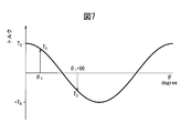
以下、図6、7を参照して、アンバランストルク演算部22における、アンバランストルクの測定、演算方法を説明する。図6は、工具マガジン120の模式図であり、黒丸は、工具マガジン120の受容部124に工具が装着されている状態を示しており、図7は、工具マガジン120の回転角に対するアンバランストルクの変化を示している。
Hereinafter, the measurement and calculation method of the unbalance torque in the unbalance torque calculation unit 22 will be described with reference to FIGS. 6 is a schematic diagram of the tool magazine 120. A black circle indicates a state in which a tool is mounted on the receiving portion 124 of the tool magazine 120. FIG. 7 shows an unbalance torque with respect to the rotation angle of the tool magazine 120. Shows changes.
図6に示すように、工具Tが工具マガジン120の周方向に不均一に装着されていると、工具マガジン120の重心は、工具マガジン120ベース部材122の中心から距離Lだけ偏った位置に移動する。このように、工具がベース部材122の周方向に偏在することにより、工具マガジン120の重心位置が中心から外れ、工具マガジン120には負荷トルクが、工具マガジン120を回転させるように作用する。今、ベース部材122と、該ベース部材122に装着されている工具とを含め工具マガジン120に作用する重力をGとし、工具マガジン120の中心から見て重心が3時の方向にあるときの工具マガジン120の角度位置をθ=0°とする。角度位置θ=0°または180°のとき、停止時負荷トルクT0は最大となりT0=GLとなる。
ここで、
T1:アンバランストルク
L:工具マガジン120の中心から重心までの距離
である。 As shown in FIG. 6, when the tool T is mounted non-uniformly in the circumferential direction of thetool magazine 120, the center of gravity of the tool magazine 120 moves to a position offset by a distance L from the center of the tool magazine 120 base member 122. To do. As described above, since the tools are unevenly distributed in the circumferential direction of the base member 122, the center of gravity of the tool magazine 120 is deviated from the center, and a load torque acts on the tool magazine 120 so as to rotate the tool magazine 120. A tool when the gravity acting on the tool magazine 120 including the base member 122 and the tool mounted on the base member 122 is G, and the center of gravity is 3 o'clock when viewed from the center of the tool magazine 120. The angle position of the magazine 120 is assumed to be θ = 0 °. When the angular position θ = 0 ° or 180 °, the stop-time load torque T 0 becomes maximum and T 0 = GL.
here,
T 1 : Unbalance torque L: Distance from the center of thetool magazine 120 to the center of gravity.
ここで、
T1:アンバランストルク
L:工具マガジン120の中心から重心までの距離
である。 As shown in FIG. 6, when the tool T is mounted non-uniformly in the circumferential direction of the
here,
T 1 : Unbalance torque L: Distance from the center of the
図6から停止時負荷トルクTは、一般的に
T=T0cosθ (1)
であるので、θ=0°の角度位置からθ=θ1だけ回転した位置に停止すると、このとき工具マガジン120に作用する停止時負荷トルクT1は以下の式から演算することができる。
T1=T0cosθ1 (2) From FIG. 6, the stop load torque T is generally T = T 0 cos θ (1)
Therefore, when stopping at a position rotated by θ = θ 1 from the angle position of θ = 0 °, the stop load torque T 1 acting on thetool magazine 120 at this time can be calculated from the following equation.
T 1 = T 0 cos θ 1 (2)
T=T0cosθ (1)
であるので、θ=0°の角度位置からθ=θ1だけ回転した位置に停止すると、このとき工具マガジン120に作用する停止時負荷トルクT1は以下の式から演算することができる。
T1=T0cosθ1 (2) From FIG. 6, the stop load torque T is generally T = T 0 cos θ (1)
Therefore, when stopping at a position rotated by θ = θ 1 from the angle position of θ = 0 °, the stop load torque T 1 acting on the
T 1 = T 0 cos θ 1 (2)
θ=φの角度位置から、工具マガジン120が更に90°回転した位置に停止したときの負荷トルクT2は以下の式(3)にて与えられる。
T2=T0cos(θ1+90)=T0sinθ1 (3) The load torque T 2 when thetool magazine 120 stops at a position rotated by 90 ° from the angle position θ = φ is given by the following equation (3).
T 2 = T 0 cos (θ 1 +90) = T 0 sin θ 1 (3)
T2=T0cos(θ1+90)=T0sinθ1 (3) The load torque T 2 when the
T 2 = T 0 cos (θ 1 +90) = T 0 sin θ 1 (3)
また、三角関数の公式から、
sin2θ1+cos2θ1=1 (4)
である。従って、式(2)~(4)より、停止時の負荷トルクの最大値であるアンバランストルクT0は以下の式から演算することができる。
T0=(T1 2+T2 2)1/2 (5)
また、式(2)から、初期位相θ1は
θ1=arccos(T1/T0) (6)
より求めることができる。 From the trigonometric formula,
sin 2 θ 1 + cos 2 θ 1 = 1 (4)
It is. Therefore, from the equations (2) to (4), the unbalance torque T 0 which is the maximum value of the load torque at the time of stop can be calculated from the following equation.
T 0 = (T 1 2 + T 2 2 ) 1/2 (5)
Further, from the equation (2), the initial phase θ 1 is θ 1 = arccos (T 1 / T 0 ) (6)
It can be obtained more.
なお、本実施形態では、回転軸120aを中心として周方向に90°離間した2つの測定点で停止時負荷トルクを測定したが、本発明はこれに限定されず、90°以上離間していてもよい。また、測定箇所も1箇所ではなく、複数箇所で同様の停止時負荷トルクを測定するようにしてもよい。
In this embodiment, the stop load torque is measured at two measurement points that are 90 ° apart from each other in the circumferential direction around the rotating shaft 120a. However, the present invention is not limited to this, and is 90 ° or more apart. Also good. Moreover, you may make it measure the same load torque at the time of a stop not at one place but at several places.
ここで、図8に示すフローチャートを参照して、アンバランストルクの測定、演算方法をより具体的に説明する。
アンバランストルクの測定、演算は、上述した工具の入れ替え作業に付随して行うことができる。工作機械100のオペレーターは、工具入れ替え作業を開始すると(ステップS10)、先ず、工具収容室136に対して手動で介入できる状態にする(ステップS12)。これは、工作機械100の操作盤(図示せず)に設けられている押ボタン(図示せず)を押下することによって行うことができ、オペレーターが工具マガジン120にアクセスしているときに、オペレーターが予期していない工具マガジン120の自動運転を禁止する。 Here, the measurement and calculation method of the unbalance torque will be described more specifically with reference to the flowchart shown in FIG.
The measurement and calculation of the unbalance torque can be performed accompanying the above-described tool replacement work. When the operator of themachine tool 100 starts the tool replacement work (step S10), first, the operator of the machine tool 100 is brought into a state where it can be manually intervened in the tool storage chamber 136 (step S12). This can be performed by pressing a push button (not shown) provided on an operation panel (not shown) of the machine tool 100. When the operator is accessing the tool magazine 120, the operator The automatic operation of the tool magazine 120 that is not anticipated is prohibited.
アンバランストルクの測定、演算は、上述した工具の入れ替え作業に付随して行うことができる。工作機械100のオペレーターは、工具入れ替え作業を開始すると(ステップS10)、先ず、工具収容室136に対して手動で介入できる状態にする(ステップS12)。これは、工作機械100の操作盤(図示せず)に設けられている押ボタン(図示せず)を押下することによって行うことができ、オペレーターが工具マガジン120にアクセスしているときに、オペレーターが予期していない工具マガジン120の自動運転を禁止する。 Here, the measurement and calculation method of the unbalance torque will be described more specifically with reference to the flowchart shown in FIG.
The measurement and calculation of the unbalance torque can be performed accompanying the above-described tool replacement work. When the operator of the
次いで、オペレーターはATCドア138aを開き(ステップS14)、工具マガジン120にアクセスして工具の入れ替え作業を行う(ステップS16)。次いで、ATCドア138aを閉じ(ステップS18)、工作機械100の操作盤(図示せず)に設けられている押ボタンを手動で操作して、NC装置への介入を解除する(ステップS20)。
Next, the operator opens the ATC door 138a (step S14), accesses the tool magazine 120, and performs a tool replacement operation (step S16). Next, the ATC door 138a is closed (step S18), and a push button provided on an operation panel (not shown) of the machine tool 100 is manually operated to cancel intervention on the NC device (step S20).
NC装置への介入が解除されると、NC装置は、工具マガジン120のアンバランストルクの測定プログラムを読み込み、アンバランストルクの測定が開始される。先ず、工具マガジン120を静止させているサーボモータ18へ現在供給されている電流値16bがアンバランストルク演算部22に取り込まれる(ステップS22)。取り込まれた電流値16bから、アンバランストルクに対抗して工具マガジン120を停止状態で保持させるために必要なトルク(T1)(停止時負荷トルク)を求めることができる。次いで、工具マガジン120を90°回転させ(ステップS24)、その回転位置に工具マガジン120を保持するために必要な電流値16bがサーボ制御部16から取り込まれる(ステップS26)。取り込まれた電流値16bから、該回転位置において、アンバランストルクに対抗して工具マガジン120を停止状態で保持させるために必要なトルク(T2)(停止時負荷トルク)を求めることができる。
When the intervention to the NC device is canceled, the NC device reads the unbalance torque measurement program of the tool magazine 120 and starts measuring the unbalance torque. First, the current value 16b currently supplied to the servo motor 18 that stops the tool magazine 120 is taken into the unbalance torque calculator 22 (step S22). From the acquired current value 16b, it is possible to obtain a torque (T 1 ) (load torque at the time of stop) necessary for holding the tool magazine 120 in a stopped state against the unbalanced torque. Next, the tool magazine 120 is rotated by 90 ° (step S24), and a current value 16b necessary to hold the tool magazine 120 at the rotational position is taken from the servo control unit 16 (step S26). From the acquired current value 16b, the torque (T 2 ) (load torque at stop) required to hold the tool magazine 120 in the stopped state against the unbalance torque at the rotational position can be obtained.
次いで、ステップS28において、求められた2つのトルク値(T1、T2)に基づき、アンバランストルク演算部22は、式(5)から最大のアンバランストルクT0を演算し、そして式(6)から初期位相θ1を演算する。
Next, in step S28, based on the obtained two torque values (T 1 , T 2 ), the unbalance torque calculator 22 calculates the maximum unbalance torque T 0 from the equation (5), and the equation ( The initial phase θ 1 is calculated from 6).
次いで、アンバランストルクキャンセル部24は、アンバランストルク演算部22で演算されたアンバランストルクT0および初期位相θ1およびエンコーダ20からの位置情報20cに基づき、工具マガジン120が、任意の角度位置θにあるときの停止時負荷トルクTを下記式(7)から演算する。
T=T0cos(θ1+θ) (7) Next, the unbalance torque cancelunit 24 determines that the tool magazine 120 has an arbitrary angular position based on the unbalance torque T 0 and the initial phase θ 1 calculated by the unbalance torque calculation unit 22 and the position information 20c from the encoder 20. The stop load torque T when it is at θ is calculated from the following equation (7).
T = T 0 cos (θ 1 + θ) (7)
T=T0cos(θ1+θ) (7) Next, the unbalance torque cancel
T = T 0 cos (θ 1 + θ) (7)
アンバランストルクキャンセル部24は、更に、工具マガジン120のサーボモータ18に供給される電流値であるトルク値16cをサーボ制御部16から受け取り、そこからアンバランストルクT0を減算することによって、トルクτを演算する。
The unbalance torque cancel unit 24 further receives a torque value 16c, which is a current value supplied to the servo motor 18 of the tool magazine 120, from the servo control unit 16, and subtracts the unbalance torque T 0 from the torque value 16c. Calculate τ.
更に、ステップS28において、慣性モーメント演算部26が、ベース部材122と、該ベース部材122に装着されている工具とを含めた工具マガジン120全体の慣性モーメントJを下記の方法にて演算する。
Further, in step S28, the inertia moment calculation unit 26 calculates the inertia moment J of the entire tool magazine 120 including the base member 122 and the tool attached to the base member 122 by the following method.
サーボモータ18が回転しているときのトルク(移動時負荷トルク)τと、工具マガジン120の慣性モーメントJとの関係は下記の式(8)で表すことができる。
τ=Jα+DV+Fu (8)
ここで、
J:慣性モーメント
α:角加速度
D:粘性減衰係数
V:角速度
F:クーロン摩擦トルク
u:速度方向を示す単位ベクトル
である。 The relationship between the torque (load torque during movement) τ when theservo motor 18 is rotating and the moment of inertia J of the tool magazine 120 can be expressed by the following equation (8).
τ = Jα + DV + Fu (8)
here,
J: moment of inertia α: angular acceleration D: viscous damping coefficient V: angular velocity F: Coulomb friction torque u: a unit vector indicating the velocity direction.
τ=Jα+DV+Fu (8)
ここで、
J:慣性モーメント
α:角加速度
D:粘性減衰係数
V:角速度
F:クーロン摩擦トルク
u:速度方向を示す単位ベクトル
である。 The relationship between the torque (load torque during movement) τ when the
τ = Jα + DV + Fu (8)
here,
J: moment of inertia α: angular acceleration D: viscous damping coefficient V: angular velocity F: Coulomb friction torque u: a unit vector indicating the velocity direction.
角速度Vおよび角加速度aは、慣性モーメント演算部26において、サーボモータ18の回転速度20d(図1)に基づいて演算することができる。速度方向を示す単位ベクトルuは、工具マガジン120が2つの回転方向の一方の向きに移動するときに正の値になり、他方の向きに移動するときに負の値になる。工具マガジン120の回転動作中に取得されるそれぞれの変数は次式のように表すことができる。
(τn)=(τ0、τ1、τ2…τk、τk+1…τm)(n=0~m) (9)
(Vn)=(V0、V1、V2…Vk、Vk+1…Vm)(n=0~m) (10)
(αn)=(α0、α1、α2…αk、αk+1…αm)(n=0~m) (11)
(un)=(u0、u1、u2…uk、uk+1…um)(n=0~m) (12) The angular velocity V and the angular acceleration a can be calculated in the moment ofinertia calculation unit 26 based on the rotational speed 20d (FIG. 1) of the servo motor 18. The unit vector u indicating the speed direction takes a positive value when the tool magazine 120 moves in one direction of the two rotational directions, and takes a negative value when moved in the other direction. Each variable acquired during the rotation operation of the tool magazine 120 can be expressed as follows.
(Τ n ) = (τ 0 , τ 1 , τ 2, τ k , τ k + 1, τ m ) (n = 0 to m) (9)
(V n ) = (V 0 , V 1 , V 2 ... V k , V k + 1 ... V m ) (n = 0 to m) (10)
(Α n ) = (α 0 , α 1 , α 2 ... Α k , α k + 1 ... Α m ) (n = 0 to m) (11)
(U n ) = (u 0 , u 1 , u 2 ... U k , u k + 1 ... U m ) (n = 0 to m) (12)
(τn)=(τ0、τ1、τ2…τk、τk+1…τm)(n=0~m) (9)
(Vn)=(V0、V1、V2…Vk、Vk+1…Vm)(n=0~m) (10)
(αn)=(α0、α1、α2…αk、αk+1…αm)(n=0~m) (11)
(un)=(u0、u1、u2…uk、uk+1…um)(n=0~m) (12) The angular velocity V and the angular acceleration a can be calculated in the moment of
(Τ n ) = (τ 0 , τ 1 , τ 2, τ k , τ k + 1, τ m ) (n = 0 to m) (9)
(V n ) = (V 0 , V 1 , V 2 ... V k , V k + 1 ... V m ) (n = 0 to m) (10)
(Α n ) = (α 0 , α 1 , α 2 ... Α k , α k + 1 ... Α m ) (n = 0 to m) (11)
(U n ) = (u 0 , u 1 , u 2 ... U k , u k + 1 ... U m ) (n = 0 to m) (12)
このように、複数のトルク(移動時負荷トルク)τの値、複数の角速度Vの値、複数の角加速度αの値、および速度方向を示す単位ベクトルuを、ステップS22~ステップS26の間に慣性モーメント演算部26に取り込むことができる。次に、式(9)に示されるトルクτnと、式(10)、式(11)および式(12)に示される変数を式(8)に代入して得られるトルクτとの差の二乗和が最小となるように、工具マガジン120の慣性モーメントJ、粘性減衰係数D、およびクーロン摩擦トルクFが演算される。すなわち、最小二乗法により、これらの変数が演算される。こうして、慣性モーメント演算部26において、工具マガジン120慣性モーメントJが演算される。慣性モーメント演算部26で演算された慣性モーメントJには、工具マガジン120のベース部材122および工具マガジン120に装着されている複数の工具の質量に基づく慣性モーメントが含まれている。
As described above, the values of the plurality of torques (load torque during movement) τ, the values of the plurality of angular velocities V, the values of the plurality of angular accelerations α, and the unit vector u indicating the speed direction are obtained during steps S22 to S26. The moment of inertia calculation unit 26 can take in the data. Next, the difference between the torque τ n shown in Equation (9) and the torque τ obtained by substituting the variables shown in Equation (10), Equation (11), and Equation (12) into Equation (8). The moment of inertia J, the viscous damping coefficient D, and the Coulomb friction torque F of the tool magazine 120 are calculated so that the sum of squares is minimized. That is, these variables are calculated by the least square method. In this way, the inertia moment calculation unit 26 calculates the tool magazine 120 inertia moment J. The inertia moment J calculated by the inertia moment calculation unit 26 includes an inertia moment based on the mass of a plurality of tools mounted on the base member 122 of the tool magazine 120 and the tool magazine 120.
次いで、ステップS30において、アンバランストルクT0が所定の閾値Tsを超えていないか否かが判定される。アンバランストルクT0が所定の閾値Tsを超えている場合(ステップS30でNOの場合)、加減速パラメータ変更部28は、加減速パラメータを最大にして、サーボ制御部16に出力すると共に、アンバランストルクT0が所定の閾値Tsを超えている旨の音響的または視覚的な警報や警告を表示するよう、アラーム表示部30に指令を出力する。加減速パラメータとしては、加速度またはゲイン等が含まれる。
Then, in step S30, the unbalance torque T 0 whether does not exceed the predetermined threshold value Ts is determined. When the unbalance torque T 0 exceeds the predetermined threshold value Ts (NO in step S30), the acceleration / deceleration parameter changing unit 28 maximizes the acceleration / deceleration parameter and outputs it to the servo control unit 16 as well as unloading. A command is output to the alarm display unit 30 so as to display an acoustic or visual warning or warning that the balance torque T 0 exceeds the predetermined threshold value T s . The acceleration / deceleration parameters include acceleration or gain.
アンバランストルクT0が所定の閾値Tsを超えていない場合(ステップS30でYESの場合)、加減速パラメータ変更部28は、加減速パラメータを変更してサーボ制御部16に出力する。加減速パラメータの変更は、工具マガジン120のアンバランストルクT0の数値の増加を、あたかも工具マガジン120の慣性モーメントが増加したかのようにみなして、慣性モーメントが増加したときと同様に変化させる。具体的には、複数のアンバランストルクT0の大きさに関連付けて、慣性モーメントに加算する慣性モーメント補正値をテーブルの形態で、制御装置10のメモリ領域に格納し、アンバランストルクT0の値に応じて、該テーブルから慣性モーメント補正値を読みだす。アンバランストルクT0の数値の増加量に応じて、どのくらいの大きさの慣性モーメント補正値を慣性モーメントに加算させればよいかは、予め実験で求めておき、アンバランストルクT0の数値と慣性モーメントの補正値とを対応させたテーブルを作成して記憶しておけばよい。慣性モーメントと慣性モーメント補正値とを加算した値に関連付けて、加減速パラメータをテーブルの形態で制御装置10のメモリ領域に格納し、慣性モーメントと慣性モーメント補正値とを加算した値に応じて該テーブルから加減速パラメータを読み出す。加減速パラメータを慣性モーメントとアンバランストルクT0の値に応じて変更することにより、慣性モーメントとアンバランストルクT0が小さいときは、より速い加減速を行うことができ、短時間で工具マガジン120を割り出すことができるようになる。
If the unbalance torque T 0 does not exceed the predetermined threshold value T s (YES in step S30), the acceleration / deceleration parameter changing unit 28 changes the acceleration / deceleration parameter and outputs it to the servo control unit 16. The acceleration / deceleration parameter is changed by changing the numerical value of the unbalance torque T 0 of the tool magazine 120 as if the moment of inertia of the tool magazine 120 has increased, and changing the value in the same manner as when the moment of inertia increased. . Specifically, an inertia moment correction value to be added to the inertia moment is stored in the memory area of the control device 10 in the form of a table in association with the magnitudes of the plurality of unbalance torques T 0 , and the unbalance torque T 0 According to the value, the inertia moment correction value is read from the table. The magnitude of the inertia moment correction value to be added to the inertia moment according to the amount of increase in the value of the unbalance torque T 0 is obtained in advance by experiment, and the value of the unbalance torque T 0 A table in which the correction values for the moment of inertia are associated with each other may be created and stored. The acceleration / deceleration parameters are stored in the memory area of the control device 10 in the form of a table in association with the value obtained by adding the inertia moment and the inertia moment correction value, and according to the value obtained by adding the inertia moment and the inertia moment correction value. Read acceleration / deceleration parameters from the table. By changing in accordance with acceleration and deceleration parameters to the values of the moment of inertia and unbalance torque T 0, when the moment of inertia and unbalance torque T 0 is small, it can be performed faster acceleration and deceleration, the tool magazine in a short time 120 can be determined.
なお、既述の実施形態では、本発明によるモータの制御方法は、工具マガジンの駆動モータを制御するようになっているが、本発明はこれに限定されず、水平または傾斜した回転送り軸周りに回転する回転送り軸に適用してもよい。例えば、図2のような工作機械において、C軸回転テーブル118を本発明の方法により制御するようにしてもよい。この場合には、一般的にCテーブル118に取り付けられたワーク116はC軸回転送り軸の回転軸線に対して重心位置が偏心しているので、C軸回転送り軸に本発明の方法を適用することが可能である。
In the above-described embodiment, the motor control method according to the present invention controls the drive motor of the tool magazine. However, the present invention is not limited to this, and the rotation feed shaft around the horizontal or inclined rotation feed shaft is used. The present invention may be applied to a rotary feed shaft that rotates in a straight line. For example, in the machine tool as shown in FIG. 2, the C-axis rotary table 118 may be controlled by the method of the present invention. In this case, since the position of the center of gravity of the workpiece 116 attached to the C table 118 is generally decentered with respect to the rotation axis of the C-axis rotation feed shaft, the method of the present invention is applied to the C-axis rotation feed shaft. It is possible.
10 制御装置
18 サーボモータ
20 エンコーダ
20a 回転速度
20b 位置情報
20c 速度情報、位置情報
20d 回転速度
22 アンバランストルク演算部
22a アンバランストルク
24 アンバランストルクキャンセル部
100 工作機械
120 工具マガジン
120a 回転軸
136 工具収納室 DESCRIPTION OFSYMBOLS 10 Control apparatus 18 Servo motor 20 Encoder 20a Rotational speed 20b Position information 20c Speed information, position information 20d Rotational speed 22 Unbalance torque calculation part 22a Unbalance torque 24 Unbalance torque cancellation part 100 Machine tool 120 Tool magazine 120a Rotation shaft 136 Tool Storage room
18 サーボモータ
20 エンコーダ
20a 回転速度
20b 位置情報
20c 速度情報、位置情報
20d 回転速度
22 アンバランストルク演算部
22a アンバランストルク
24 アンバランストルクキャンセル部
100 工作機械
120 工具マガジン
120a 回転軸
136 工具収納室 DESCRIPTION OF
Claims (7)
- 水平または傾斜した回転軸周りに回転する回転軸装置のモータの制御方法において、
前記回転軸装置を少なくとも2ヶ所の割出位置に割出し、
前記割出位置で、回転軸装置に作用する停止負荷トルクを測定し、
複数の前記停止時負荷トルクから、停止時負荷トルクが最大となる割出位置での停止時負荷トルクであるアンバランストルクを算出し、
前記アンバランストルクに基づいて回転軸装置のモータを制御することを特徴としたモータの制御方法。 In a method of controlling a motor of a rotary shaft device that rotates around a horizontal or inclined rotary shaft,
Indexing the rotary shaft device to at least two index positions,
Measure the stop load torque acting on the rotary shaft device at the index position,
From the plurality of stop load torques, an unbalance torque that is a stop load torque at an index position where the stop load torque is maximum is calculated.
A motor control method, comprising: controlling a motor of a rotary shaft device based on the unbalance torque. - 前記回転軸周りに90°離間した2ヶ所を割出位置とし、アンバランストルクは該2ヶ所の各々における停止時負荷トルクの2乗の和の平方根である請求項1に記載のモータの制御方法。 2. The motor control method according to claim 1, wherein two positions 90 ° apart about the rotation axis are set as index positions, and the unbalance torque is a square root of a sum of squares of stop load torque at each of the two positions. .
- 測定した各停止時負荷トルクから停止時負荷トルクが最大となる割出位置を求め、前記回転軸装置の各位相における停止時負荷トルクを算出し、測定した移動時負荷トルクから各位相におけるアンバランストルクを減算して、アンバランストルクを除いた移動時負荷トルクから回転軸装置の慣性モーメントを算出するようにした請求項1または2に記載のモータの制御方法。 From the measured stop load torque, the index position where the stop load torque becomes maximum is obtained, the stop load torque in each phase of the rotary shaft device is calculated, and the unbalance in each phase is calculated from the measured travel load torque. The motor control method according to claim 1 or 2, wherein a torque is subtracted to calculate a moment of inertia of the rotary shaft device from a load torque during movement excluding an unbalanced torque.
- 算出した慣性モーメントに関連付けて予め設定しておいたアンバランストルクの大きさに応じた慣性モーメントの補正量を加算し、補正量が加算された慣性モーメントに基づいて前記回転軸装置の加減速パラメータを決定するようにした請求項3に記載のモータの制御方法。 A correction amount of the inertia moment according to the magnitude of the unbalance torque set in advance in association with the calculated inertia moment is added, and the acceleration / deceleration parameter of the rotary shaft device is based on the inertia moment to which the correction amount is added The motor control method according to claim 3, wherein the motor is determined.
- アンバランストルクが、所定の閾値を超える場合には警報または警告を発するようにした請求項1に記載のモータの制御方法。 2. The motor control method according to claim 1, wherein an alarm or a warning is issued when the unbalance torque exceeds a predetermined threshold value.
- 水平または傾斜した回転軸周りに回転する回転軸装置のモータの制御装置において、
前記回転軸装置を少なくとも2ヶ所の割出位置に割出す手段と、
前記割出位置の各々で、回転軸装置に作用する停止負荷トルクを測定する手段と、
複数の前記停止時負荷トルクから、停止時負荷トルクが最大となる割出位置での停止時負荷トルクであるアンバランストルクを算出する手段と、
前記アンバランストルクに基づいて回転軸装置のモータを制御することを特徴としたモータの制御装置。 In a control device for a motor of a rotating shaft device that rotates around a horizontal or inclined rotating shaft,
Means for indexing the rotary shaft device to at least two index positions;
Means for measuring a stop load torque acting on the rotary shaft device at each of the index positions;
Means for calculating an unbalance torque that is a stop load torque at an index position at which the stop load torque is maximized from the plurality of stop load torques;
A motor control device that controls a motor of a rotary shaft device based on the unbalance torque. - 請求項6に記載のモータの制御装置によって制御される工具マガジンを備えた工作機械。 A machine tool comprising a tool magazine controlled by the motor control device according to claim 6.
Priority Applications (5)
| Application Number | Priority Date | Filing Date | Title |
|---|---|---|---|
| CN201580074519.7A CN107206559B (en) | 2015-02-27 | 2015-02-27 | Motor control method, motor control device, and machine tool provided with tool magazine |
| PCT/JP2015/055899 WO2016135958A1 (en) | 2015-02-27 | 2015-02-27 | Motor control method and control device, and machine tool provided with tool magazine |
| EP15883252.7A EP3263275B1 (en) | 2015-02-27 | 2015-02-27 | Motor control method and control device, and machine tool provided with tool magazine |
| JP2017501804A JP6407402B2 (en) | 2015-02-27 | 2015-02-27 | Motor control method, control device, and machine tool provided with tool magazine |
| US15/553,754 US10324449B2 (en) | 2015-02-27 | 2015-02-27 | Motor controlling method, control device and machine tool |
Applications Claiming Priority (1)
| Application Number | Priority Date | Filing Date | Title |
|---|---|---|---|
| PCT/JP2015/055899 WO2016135958A1 (en) | 2015-02-27 | 2015-02-27 | Motor control method and control device, and machine tool provided with tool magazine |
Publications (1)
| Publication Number | Publication Date |
|---|---|
| WO2016135958A1 true WO2016135958A1 (en) | 2016-09-01 |
Family
ID=56788063
Family Applications (1)
| Application Number | Title | Priority Date | Filing Date |
|---|---|---|---|
| PCT/JP2015/055899 WO2016135958A1 (en) | 2015-02-27 | 2015-02-27 | Motor control method and control device, and machine tool provided with tool magazine |
Country Status (5)
| Country | Link |
|---|---|
| US (1) | US10324449B2 (en) |
| EP (1) | EP3263275B1 (en) |
| JP (1) | JP6407402B2 (en) |
| CN (1) | CN107206559B (en) |
| WO (1) | WO2016135958A1 (en) |
Cited By (7)
| Publication number | Priority date | Publication date | Assignee | Title |
|---|---|---|---|---|
| EP3321755A1 (en) * | 2016-11-10 | 2018-05-16 | Nakamura-Tome Precision Industry Co., Ltd | Machine tool and parameter adjustment method therefor |
| TWI630977B (en) * | 2016-09-09 | 2018-08-01 | 日商牧野銑床製作所股份有限公司 | Working machinery |
| DE102018211561A1 (en) | 2017-07-19 | 2019-01-24 | Fanuc Corporation | Servo motor control unit |
| CN109304639A (en) * | 2017-07-26 | 2019-02-05 | 巨浪有限公司 | For determining the device of high load capacity position in lathe |
| CN109689289A (en) * | 2016-09-09 | 2019-04-26 | 株式会社牧野铣床制作所 | Lathe |
| KR20190086430A (en) * | 2016-11-16 | 2019-07-22 | 호코스 가부시키가이샤 | Automatic tool changer |
| CN111360572A (en) * | 2020-03-31 | 2020-07-03 | 新代科技(苏州)有限公司 | Tool magazine control system and control method thereof |
Families Citing this family (8)
| Publication number | Priority date | Publication date | Assignee | Title |
|---|---|---|---|---|
| DE102016209833B4 (en) * | 2016-06-03 | 2019-10-31 | Volkswagen Aktiengesellschaft | Method and device for determining a driver's manual torque on a steering wheel of a vehicle |
| JP6836143B2 (en) * | 2016-12-27 | 2021-02-24 | 株式会社ジェイテクト | Machine Tools |
| JP7385298B2 (en) * | 2018-05-17 | 2023-11-22 | アーカス テクノロジー インコーポレイテッド | Motion system state management using existing servo drive variables |
| JP7036071B2 (en) * | 2019-03-18 | 2022-03-15 | ブラザー工業株式会社 | Numerical control device, numerical control program, and storage device that stores the numerical control program |
| CN112536643B (en) * | 2019-09-23 | 2023-01-24 | 富鼎电子科技(嘉善)有限公司 | Machine health monitoring method and device and computer readable storage medium |
| CN113742880A (en) * | 2020-05-27 | 2021-12-03 | 台达电子工业股份有限公司 | Method for predicting and compensating friction force of feeding system and computer readable storage medium |
| TW202147181A (en) * | 2020-06-10 | 2021-12-16 | 淡江大學 | Three-finger mechanical gripper system and training method thereof |
| CN112643377A (en) * | 2020-12-08 | 2021-04-13 | 常州市利凯数控科技有限公司 | Stable in structure's rotatory tool changing device |
Citations (3)
| Publication number | Priority date | Publication date | Assignee | Title |
|---|---|---|---|---|
| JP2001062672A (en) * | 1999-08-31 | 2001-03-13 | Okuma Corp | Numerical control device |
| JP2005224896A (en) * | 2004-02-13 | 2005-08-25 | Brother Ind Ltd | Conveying device, method for deciding conveyance acceleration of conveying device, and computer program |
| JP2009034794A (en) * | 2007-08-03 | 2009-02-19 | Fanuc Ltd | Machine tool |
Family Cites Families (11)
| Publication number | Priority date | Publication date | Assignee | Title |
|---|---|---|---|---|
| JPS5853733A (en) * | 1981-09-28 | 1983-03-30 | Ricoh Co Ltd | Measuring method for static unbalance amount |
| JP2722004B2 (en) * | 1989-10-28 | 1998-03-04 | オ−クマ株式会社 | Adaptive control method of turret turning speed |
| JP2002046042A (en) * | 2000-08-02 | 2002-02-12 | Murata Mach Ltd | Machine tool |
| CN100420928C (en) * | 2003-12-30 | 2008-09-24 | 丰田自动车株式会社 | Unbalance measurement method and device for long shaft rotator |
| JP2007016288A (en) * | 2005-07-08 | 2007-01-25 | Toyota Motor Corp | Method for manufacturing sliding member coated with bearing material and sliding member coated with bearing material |
| US7551411B2 (en) * | 2005-10-12 | 2009-06-23 | Black & Decker Inc. | Control and protection methodologies for a motor control module |
| NZ588159A (en) * | 2010-09-23 | 2014-01-31 | Powerbyproxi Ltd | A contactless power transfer system |
| JP5003832B1 (en) * | 2011-03-08 | 2012-08-15 | 株式会社安川電機 | Motor control device and motor control method |
| JP5291820B2 (en) * | 2011-05-26 | 2013-09-18 | ファナック株式会社 | Oscillator control device and machine tool |
| JP5751433B2 (en) * | 2013-02-06 | 2015-07-22 | 株式会社安川電機 | Motor control device and motor control method |
| CN203944859U (en) * | 2014-07-14 | 2014-11-19 | 林宇 | Novel cutter tower |
-
2015
- 2015-02-27 US US15/553,754 patent/US10324449B2/en active Active
- 2015-02-27 WO PCT/JP2015/055899 patent/WO2016135958A1/en active Application Filing
- 2015-02-27 EP EP15883252.7A patent/EP3263275B1/en active Active
- 2015-02-27 JP JP2017501804A patent/JP6407402B2/en active Active
- 2015-02-27 CN CN201580074519.7A patent/CN107206559B/en active Active
Patent Citations (3)
| Publication number | Priority date | Publication date | Assignee | Title |
|---|---|---|---|---|
| JP2001062672A (en) * | 1999-08-31 | 2001-03-13 | Okuma Corp | Numerical control device |
| JP2005224896A (en) * | 2004-02-13 | 2005-08-25 | Brother Ind Ltd | Conveying device, method for deciding conveyance acceleration of conveying device, and computer program |
| JP2009034794A (en) * | 2007-08-03 | 2009-02-19 | Fanuc Ltd | Machine tool |
Non-Patent Citations (1)
| Title |
|---|
| See also references of EP3263275A4 * |
Cited By (13)
| Publication number | Priority date | Publication date | Assignee | Title |
|---|---|---|---|---|
| CN109689289A (en) * | 2016-09-09 | 2019-04-26 | 株式会社牧野铣床制作所 | Lathe |
| TWI630977B (en) * | 2016-09-09 | 2018-08-01 | 日商牧野銑床製作所股份有限公司 | Working machinery |
| US11045916B2 (en) * | 2016-09-09 | 2021-06-29 | Makino Milling Machine Co., Ltd. | Machine tool |
| EP3321755A1 (en) * | 2016-11-10 | 2018-05-16 | Nakamura-Tome Precision Industry Co., Ltd | Machine tool and parameter adjustment method therefor |
| JPWO2018092794A1 (en) * | 2016-11-16 | 2019-10-17 | ホーコス株式会社 | Automatic tool changer |
| KR20190086430A (en) * | 2016-11-16 | 2019-07-22 | 호코스 가부시키가이샤 | Automatic tool changer |
| US11090776B2 (en) * | 2016-11-16 | 2021-08-17 | Horkos Corp | Automatic tool changer |
| KR102299753B1 (en) | 2016-11-16 | 2021-09-09 | 호코스 가부시키가이샤 | automatic tool changer |
| DE102018211561A1 (en) | 2017-07-19 | 2019-01-24 | Fanuc Corporation | Servo motor control unit |
| US11347197B2 (en) | 2017-07-19 | 2022-05-31 | Fanuc Corporation | Servo motor controller |
| CN109304639A (en) * | 2017-07-26 | 2019-02-05 | 巨浪有限公司 | For determining the device of high load capacity position in lathe |
| US10935363B2 (en) | 2017-07-26 | 2021-03-02 | Chiron-Werke Gmbh & Co. Kg | Device for detecting highly stressed position in a machining tool |
| CN111360572A (en) * | 2020-03-31 | 2020-07-03 | 新代科技(苏州)有限公司 | Tool magazine control system and control method thereof |
Also Published As
| Publication number | Publication date |
|---|---|
| JPWO2016135958A1 (en) | 2017-09-28 |
| CN107206559B (en) | 2020-04-28 |
| JP6407402B2 (en) | 2018-10-17 |
| EP3263275A1 (en) | 2018-01-03 |
| EP3263275A4 (en) | 2018-11-21 |
| US20180032052A1 (en) | 2018-02-01 |
| EP3263275B1 (en) | 2022-04-27 |
| CN107206559A (en) | 2017-09-26 |
| US10324449B2 (en) | 2019-06-18 |
Similar Documents
| Publication | Publication Date | Title |
|---|---|---|
| JP6407402B2 (en) | Motor control method, control device, and machine tool provided with tool magazine | |
| Altintas et al. | Sliding mode controller design for high speed feed drives | |
| JP3703664B2 (en) | Backlash correction device | |
| JP5673855B2 (en) | Machine Tools | |
| EP2966521A1 (en) | Working machine feed shaft control method and feed shaft control device | |
| US7847502B2 (en) | Device and method for controlling machine tool | |
| JP6877729B2 (en) | Parameter adjustment system for servo motor control device in machine tools | |
| JP2019003646A (en) | Controller for motor | |
| JP4299865B2 (en) | Machine tool control apparatus and control method | |
| KR100450455B1 (en) | Servo control method | |
| KR20220034118A (en) | Machine tool and method for generating by generating method a rotating part having a grooved profile | |
| JP2003005838A (en) | Method for servo control | |
| JP2015143969A (en) | Machine tool control device, machine tool control method, and program | |
| JP5321515B2 (en) | Numerical control device for machine tools | |
| CN109324568A (en) | Position control | |
| JP6068779B2 (en) | Control devices for linear and rotary robots | |
| JP3686015B2 (en) | Orbit boring control method | |
| JP5369718B2 (en) | Machine Tools | |
| JP7017537B2 (en) | Machine tools, machining systems and management systems | |
| JP2717747B2 (en) | Tool changer | |
| JP4754708B2 (en) | Numerical control device for machine tools | |
| JP2003157114A (en) | Method and device for lost motion correction | |
| JP2016190305A (en) | Parameter setting method of positioner, parameter setting device, and positioner having the parameter setting device | |
| WO2019239594A1 (en) | Numerical control device | |
| CN111857045B (en) | Numerical control device and machine tool |
Legal Events
| Date | Code | Title | Description |
|---|---|---|---|
| 121 | Ep: the epo has been informed by wipo that ep was designated in this application |
Ref document number: 15883252 Country of ref document: EP Kind code of ref document: A1 |
|
| ENP | Entry into the national phase |
Ref document number: 2017501804 Country of ref document: JP Kind code of ref document: A |
|
| NENP | Non-entry into the national phase |
Ref country code: DE |
|
| REEP | Request for entry into the european phase |
Ref document number: 2015883252 Country of ref document: EP |