EP3263275B1 - Motor control method and control device, and machine tool provided with tool magazine - Google Patents
Motor control method and control device, and machine tool provided with tool magazine Download PDFInfo
- Publication number
- EP3263275B1 EP3263275B1 EP15883252.7A EP15883252A EP3263275B1 EP 3263275 B1 EP3263275 B1 EP 3263275B1 EP 15883252 A EP15883252 A EP 15883252A EP 3263275 B1 EP3263275 B1 EP 3263275B1
- Authority
- EP
- European Patent Office
- Prior art keywords
- torque
- rotating shaft
- unbalance
- tool magazine
- tool
- Prior art date
- Legal status (The legal status is an assumption and is not a legal conclusion. Google has not performed a legal analysis and makes no representation as to the accuracy of the status listed.)
- Active
Links
- 238000000034 method Methods 0.000 title claims description 20
- 230000001133 acceleration Effects 0.000 claims description 23
- 238000012937 correction Methods 0.000 claims description 8
- 230000002093 peripheral effect Effects 0.000 description 9
- 230000005484 gravity Effects 0.000 description 8
- 238000005192 partition Methods 0.000 description 3
- 238000012545 processing Methods 0.000 description 3
- 239000013598 vector Substances 0.000 description 3
- 238000013016 damping Methods 0.000 description 2
- 230000003247 decreasing effect Effects 0.000 description 2
- 230000000881 depressing effect Effects 0.000 description 2
- 238000010586 diagram Methods 0.000 description 2
- 230000006870 function Effects 0.000 description 2
- 238000005259 measurement Methods 0.000 description 2
- 238000012986 modification Methods 0.000 description 2
- 230000004048 modification Effects 0.000 description 2
- 230000000007 visual effect Effects 0.000 description 2
- 230000003044 adaptive effect Effects 0.000 description 1
- 230000003466 anti-cipated effect Effects 0.000 description 1
- 230000000694 effects Effects 0.000 description 1
- 239000000314 lubricant Substances 0.000 description 1
- 238000003754 machining Methods 0.000 description 1
Images


Classifications
-
- B—PERFORMING OPERATIONS; TRANSPORTING
- B23—MACHINE TOOLS; METAL-WORKING NOT OTHERWISE PROVIDED FOR
- B23Q—DETAILS, COMPONENTS, OR ACCESSORIES FOR MACHINE TOOLS, e.g. ARRANGEMENTS FOR COPYING OR CONTROLLING; MACHINE TOOLS IN GENERAL CHARACTERISED BY THE CONSTRUCTION OF PARTICULAR DETAILS OR COMPONENTS; COMBINATIONS OR ASSOCIATIONS OF METAL-WORKING MACHINES, NOT DIRECTED TO A PARTICULAR RESULT
- B23Q17/00—Arrangements for observing, indicating or measuring on machine tools
-
- G—PHYSICS
- G05—CONTROLLING; REGULATING
- G05B—CONTROL OR REGULATING SYSTEMS IN GENERAL; FUNCTIONAL ELEMENTS OF SUCH SYSTEMS; MONITORING OR TESTING ARRANGEMENTS FOR SUCH SYSTEMS OR ELEMENTS
- G05B19/00—Programme-control systems
- G05B19/02—Programme-control systems electric
- G05B19/18—Numerical control [NC], i.e. automatically operating machines, in particular machine tools, e.g. in a manufacturing environment, so as to execute positioning, movement or co-ordinated operations by means of programme data in numerical form
- G05B19/402—Numerical control [NC], i.e. automatically operating machines, in particular machine tools, e.g. in a manufacturing environment, so as to execute positioning, movement or co-ordinated operations by means of programme data in numerical form characterised by control arrangements for positioning, e.g. centring a tool relative to a hole in the workpiece, additional detection means to correct position
-
- B—PERFORMING OPERATIONS; TRANSPORTING
- B23—MACHINE TOOLS; METAL-WORKING NOT OTHERWISE PROVIDED FOR
- B23Q—DETAILS, COMPONENTS, OR ACCESSORIES FOR MACHINE TOOLS, e.g. ARRANGEMENTS FOR COPYING OR CONTROLLING; MACHINE TOOLS IN GENERAL CHARACTERISED BY THE CONSTRUCTION OF PARTICULAR DETAILS OR COMPONENTS; COMBINATIONS OR ASSOCIATIONS OF METAL-WORKING MACHINES, NOT DIRECTED TO A PARTICULAR RESULT
- B23Q11/00—Accessories fitted to machine tools for keeping tools or parts of the machine in good working condition or for cooling work; Safety devices specially combined with or arranged in, or specially adapted for use in connection with, machine tools
- B23Q11/001—Arrangements compensating weight or flexion on parts of the machine
- B23Q11/0028—Arrangements compensating weight or flexion on parts of the machine by actively reacting to a change of the configuration of the machine
-
- B—PERFORMING OPERATIONS; TRANSPORTING
- B23—MACHINE TOOLS; METAL-WORKING NOT OTHERWISE PROVIDED FOR
- B23Q—DETAILS, COMPONENTS, OR ACCESSORIES FOR MACHINE TOOLS, e.g. ARRANGEMENTS FOR COPYING OR CONTROLLING; MACHINE TOOLS IN GENERAL CHARACTERISED BY THE CONSTRUCTION OF PARTICULAR DETAILS OR COMPONENTS; COMBINATIONS OR ASSOCIATIONS OF METAL-WORKING MACHINES, NOT DIRECTED TO A PARTICULAR RESULT
- B23Q11/00—Accessories fitted to machine tools for keeping tools or parts of the machine in good working condition or for cooling work; Safety devices specially combined with or arranged in, or specially adapted for use in connection with, machine tools
- B23Q11/08—Protective coverings for parts of machine tools; Splash guards
- B23Q11/0891—Protective coverings for parts of machine tools; Splash guards arranged between the working area and the operator
-
- B—PERFORMING OPERATIONS; TRANSPORTING
- B23—MACHINE TOOLS; METAL-WORKING NOT OTHERWISE PROVIDED FOR
- B23Q—DETAILS, COMPONENTS, OR ACCESSORIES FOR MACHINE TOOLS, e.g. ARRANGEMENTS FOR COPYING OR CONTROLLING; MACHINE TOOLS IN GENERAL CHARACTERISED BY THE CONSTRUCTION OF PARTICULAR DETAILS OR COMPONENTS; COMBINATIONS OR ASSOCIATIONS OF METAL-WORKING MACHINES, NOT DIRECTED TO A PARTICULAR RESULT
- B23Q16/00—Equipment for precise positioning of tool or work into particular locations not otherwise provided for
- B23Q16/02—Indexing equipment
-
- B—PERFORMING OPERATIONS; TRANSPORTING
- B23—MACHINE TOOLS; METAL-WORKING NOT OTHERWISE PROVIDED FOR
- B23Q—DETAILS, COMPONENTS, OR ACCESSORIES FOR MACHINE TOOLS, e.g. ARRANGEMENTS FOR COPYING OR CONTROLLING; MACHINE TOOLS IN GENERAL CHARACTERISED BY THE CONSTRUCTION OF PARTICULAR DETAILS OR COMPONENTS; COMBINATIONS OR ASSOCIATIONS OF METAL-WORKING MACHINES, NOT DIRECTED TO A PARTICULAR RESULT
- B23Q17/00—Arrangements for observing, indicating or measuring on machine tools
- B23Q17/22—Arrangements for observing, indicating or measuring on machine tools for indicating or measuring existing or desired position of tool or work
-
- B—PERFORMING OPERATIONS; TRANSPORTING
- B23—MACHINE TOOLS; METAL-WORKING NOT OTHERWISE PROVIDED FOR
- B23Q—DETAILS, COMPONENTS, OR ACCESSORIES FOR MACHINE TOOLS, e.g. ARRANGEMENTS FOR COPYING OR CONTROLLING; MACHINE TOOLS IN GENERAL CHARACTERISED BY THE CONSTRUCTION OF PARTICULAR DETAILS OR COMPONENTS; COMBINATIONS OR ASSOCIATIONS OF METAL-WORKING MACHINES, NOT DIRECTED TO A PARTICULAR RESULT
- B23Q3/00—Devices holding, supporting, or positioning work or tools, of a kind normally removable from the machine
- B23Q3/155—Arrangements for automatic insertion or removal of tools, e.g. combined with manual handling
- B23Q3/1552—Arrangements for automatic insertion or removal of tools, e.g. combined with manual handling parts of devices for automatically inserting or removing tools
- B23Q3/15526—Storage devices; Drive mechanisms therefor
-
- B—PERFORMING OPERATIONS; TRANSPORTING
- B23—MACHINE TOOLS; METAL-WORKING NOT OTHERWISE PROVIDED FOR
- B23Q—DETAILS, COMPONENTS, OR ACCESSORIES FOR MACHINE TOOLS, e.g. ARRANGEMENTS FOR COPYING OR CONTROLLING; MACHINE TOOLS IN GENERAL CHARACTERISED BY THE CONSTRUCTION OF PARTICULAR DETAILS OR COMPONENTS; COMBINATIONS OR ASSOCIATIONS OF METAL-WORKING MACHINES, NOT DIRECTED TO A PARTICULAR RESULT
- B23Q3/00—Devices holding, supporting, or positioning work or tools, of a kind normally removable from the machine
- B23Q3/155—Arrangements for automatic insertion or removal of tools, e.g. combined with manual handling
- B23Q3/157—Arrangements for automatic insertion or removal of tools, e.g. combined with manual handling of rotary tools
- B23Q3/15713—Arrangements for automatic insertion or removal of tools, e.g. combined with manual handling of rotary tools a transfer device taking a single tool from a storage device and inserting it in a spindle
- B23Q3/1572—Arrangements for automatic insertion or removal of tools, e.g. combined with manual handling of rotary tools a transfer device taking a single tool from a storage device and inserting it in a spindle the storage device comprising rotating or circulating storing means
- B23Q3/15722—Rotary discs or drums
-
- B—PERFORMING OPERATIONS; TRANSPORTING
- B23—MACHINE TOOLS; METAL-WORKING NOT OTHERWISE PROVIDED FOR
- B23Q—DETAILS, COMPONENTS, OR ACCESSORIES FOR MACHINE TOOLS, e.g. ARRANGEMENTS FOR COPYING OR CONTROLLING; MACHINE TOOLS IN GENERAL CHARACTERISED BY THE CONSTRUCTION OF PARTICULAR DETAILS OR COMPONENTS; COMBINATIONS OR ASSOCIATIONS OF METAL-WORKING MACHINES, NOT DIRECTED TO A PARTICULAR RESULT
- B23Q5/00—Driving or feeding mechanisms; Control arrangements therefor
- B23Q5/22—Feeding members carrying tools or work
- B23Q5/34—Feeding other members supporting tools or work, e.g. saddles, tool-slides, through mechanical transmission
-
- G—PHYSICS
- G01—MEASURING; TESTING
- G01M—TESTING STATIC OR DYNAMIC BALANCE OF MACHINES OR STRUCTURES; TESTING OF STRUCTURES OR APPARATUS, NOT OTHERWISE PROVIDED FOR
- G01M1/00—Testing static or dynamic balance of machines or structures
- G01M1/10—Determining the moment of inertia
-
- G—PHYSICS
- G01—MEASURING; TESTING
- G01M—TESTING STATIC OR DYNAMIC BALANCE OF MACHINES OR STRUCTURES; TESTING OF STRUCTURES OR APPARATUS, NOT OTHERWISE PROVIDED FOR
- G01M1/00—Testing static or dynamic balance of machines or structures
- G01M1/14—Determining unbalance
-
- G—PHYSICS
- G01—MEASURING; TESTING
- G01M—TESTING STATIC OR DYNAMIC BALANCE OF MACHINES OR STRUCTURES; TESTING OF STRUCTURES OR APPARATUS, NOT OTHERWISE PROVIDED FOR
- G01M1/00—Testing static or dynamic balance of machines or structures
- G01M1/14—Determining unbalance
- G01M1/16—Determining unbalance by oscillating or rotating the body to be tested
- G01M1/28—Determining unbalance by oscillating or rotating the body to be tested with special adaptations for determining unbalance of the body in situ, e.g. of vehicle wheels
-
- G—PHYSICS
- G05—CONTROLLING; REGULATING
- G05B—CONTROL OR REGULATING SYSTEMS IN GENERAL; FUNCTIONAL ELEMENTS OF SUCH SYSTEMS; MONITORING OR TESTING ARRANGEMENTS FOR SUCH SYSTEMS OR ELEMENTS
- G05B19/00—Programme-control systems
- G05B19/02—Programme-control systems electric
- G05B19/18—Numerical control [NC], i.e. automatically operating machines, in particular machine tools, e.g. in a manufacturing environment, so as to execute positioning, movement or co-ordinated operations by means of programme data in numerical form
- G05B19/404—Numerical control [NC], i.e. automatically operating machines, in particular machine tools, e.g. in a manufacturing environment, so as to execute positioning, movement or co-ordinated operations by means of programme data in numerical form characterised by control arrangements for compensation, e.g. for backlash, overshoot, tool offset, tool wear, temperature, machine construction errors, load, inertia
-
- G—PHYSICS
- G05—CONTROLLING; REGULATING
- G05B—CONTROL OR REGULATING SYSTEMS IN GENERAL; FUNCTIONAL ELEMENTS OF SUCH SYSTEMS; MONITORING OR TESTING ARRANGEMENTS FOR SUCH SYSTEMS OR ELEMENTS
- G05B19/00—Programme-control systems
- G05B19/02—Programme-control systems electric
- G05B19/18—Numerical control [NC], i.e. automatically operating machines, in particular machine tools, e.g. in a manufacturing environment, so as to execute positioning, movement or co-ordinated operations by means of programme data in numerical form
- G05B19/416—Numerical control [NC], i.e. automatically operating machines, in particular machine tools, e.g. in a manufacturing environment, so as to execute positioning, movement or co-ordinated operations by means of programme data in numerical form characterised by control of velocity, acceleration or deceleration
-
- B—PERFORMING OPERATIONS; TRANSPORTING
- B23—MACHINE TOOLS; METAL-WORKING NOT OTHERWISE PROVIDED FOR
- B23Q—DETAILS, COMPONENTS, OR ACCESSORIES FOR MACHINE TOOLS, e.g. ARRANGEMENTS FOR COPYING OR CONTROLLING; MACHINE TOOLS IN GENERAL CHARACTERISED BY THE CONSTRUCTION OF PARTICULAR DETAILS OR COMPONENTS; COMBINATIONS OR ASSOCIATIONS OF METAL-WORKING MACHINES, NOT DIRECTED TO A PARTICULAR RESULT
- B23Q16/00—Equipment for precise positioning of tool or work into particular locations not otherwise provided for
- B23Q16/02—Indexing equipment
- B23Q16/022—Indexing equipment in which only the indexing movement is of importance
- B23Q16/025—Indexing equipment in which only the indexing movement is of importance by converting a continuous movement into a rotary indexing movement
-
- B—PERFORMING OPERATIONS; TRANSPORTING
- B23—MACHINE TOOLS; METAL-WORKING NOT OTHERWISE PROVIDED FOR
- B23Q—DETAILS, COMPONENTS, OR ACCESSORIES FOR MACHINE TOOLS, e.g. ARRANGEMENTS FOR COPYING OR CONTROLLING; MACHINE TOOLS IN GENERAL CHARACTERISED BY THE CONSTRUCTION OF PARTICULAR DETAILS OR COMPONENTS; COMBINATIONS OR ASSOCIATIONS OF METAL-WORKING MACHINES, NOT DIRECTED TO A PARTICULAR RESULT
- B23Q3/00—Devices holding, supporting, or positioning work or tools, of a kind normally removable from the machine
- B23Q3/155—Arrangements for automatic insertion or removal of tools, e.g. combined with manual handling
- B23Q3/157—Arrangements for automatic insertion or removal of tools, e.g. combined with manual handling of rotary tools
- B23Q3/15713—Arrangements for automatic insertion or removal of tools, e.g. combined with manual handling of rotary tools a transfer device taking a single tool from a storage device and inserting it in a spindle
-
- G—PHYSICS
- G05—CONTROLLING; REGULATING
- G05B—CONTROL OR REGULATING SYSTEMS IN GENERAL; FUNCTIONAL ELEMENTS OF SUCH SYSTEMS; MONITORING OR TESTING ARRANGEMENTS FOR SUCH SYSTEMS OR ELEMENTS
- G05B2219/00—Program-control systems
- G05B2219/30—Nc systems
- G05B2219/41—Servomotor, servo controller till figures
- G05B2219/41398—Estimate twist between motor and load, observe motor position and speed
Definitions
- the invention relates to a method for controlling a motor in consideration of unbalance torque, a control device for carrying out the method and a machine tool provided with a tool magazine.
- Patent Literature 1 describes a method for controlling a motor wherein the moment of inertia and the unbalance torque of a tool magazine are estimated based on the shapes and the distribution of the tools mounted to the tool magazine, and the optimum acceleration is determined by adding/subtracting the unbalance torque.
- Patent Literature 1 JP-A-2005-224896
- JP H03 142108 A An example of an adaptive control method for controlling the turret turning speed of a machine tool taking into account an unbalance torque of the turret is described in JP H03 142108 A .
- the invention is directed to solve the prior art problem, and the objective of the invention is to ensure the estimation of the unbalance torque in a rotating shaft apparatus in which the load torque is changed by moving unevenly distributed masses, whereby reducing the movement duration of the rotating shaft apparatus.
- a method of controlling a motor of a rotating shaft apparatus configured to rotate about a horizontal or inclined rotational axis, the method comprising the steps of positioning the rotating shaft apparatus at at least two rotational positions, measuring a stopping load torque acting on the rotating shaft apparatus at each of the rotational positions, calculating an unbalance torque based on the measured stopping load torques, and controlling the motor of the rotating shaft apparatus based on the unbalance torque is provided.
- an apparatus according to claim 6 is provided.
- the stopping load torques are measured, and the unbalance torque, which is the stopping load torque at one of the rotational positions where the stopping load torque is the maximum, is calculated, so that the motor of the rotating shaft apparatus is optimally controlled, based on the unbalance torque, whereby enabling to increase the driving speed of the rotating shaft apparatus, and reducing the sudden changes in the driving speed.
- the machine tool 100 forms a horizontal machining center, and comprises a bed 102, providing a base fixed to a floor of a factory, a Z-axis slider 112 provided for reciprocating along a pair of Z-axis guide rails 102b, extending in a front-rear direction or a Z-axis direction (the left and right direction in Figure 1 ), on a top face of a front part (the left side in Figure 2 ) of the bed 102, a rotary table 114 provided for rotationally feeding in a B-axis direction about a vertical axis, on a top face of the Z-axis slider 112, a column 104 provided for reciprocating along a pair of X-axis guide rails 102a extending in a left-right direction or an X-axis direction (perpendicular direction to the plane of Figure 1 ), on a top face of a rear part (the right side in Figure 1 ), on a top face of a rear part (the right side in Figure 1 ), on
- a spindle head 108 configured to support a spindle 110 for rotation about a horizontal axis O s , is mounted to the Y-axis slider.
- the machine tool 100 comprises an X-axis feed device (not shown) configured to drive the column 104 in the X-axis direction, a Y-axis feed device (not shown) configured to drive the Y-axis slider 106 in the Y-axis direction, and a Z-axis feed device (not shown) configured to drive the Z-axis slider 112 in the Z-axis direction.
- a C-axis table 118 is mounted to the rotary table 112 via a mount 116.
- a workpiece W is mounted to the C-axis table 118 so as to face a tool T attached to the end of the spindle 110.
- the horizontal machining center formed by the machine tool 100 comprises a tool magazine 120 configured to accommodate a plurality of tools necessary for the process in the machine tool 100, a tool changer configured to change a tool T attached to the end of the spindle 110 of the machine tool 100 with one of the tools accommodated in the tool magazine 120 in accordance with a command from an NC device (not shown) of the machine tool 100.
- the machine tool 100, the tool magazine 12 and the tool changer 140 are enclosed by a cover 130.
- the tool magazine 120 provides a rotating shaft apparatus.
- the cover 130 comprises a partition 132 configured to divide the interior space of the cover into a processing chamber 134 and a tool accommodating chamber 136.
- the machine tool 100 is placed in the processing chamber for machining a workpiece, while the tool magazine and the tool changer 140 are placed in the tool accommodating chamber 136.
- the partition 132 defines an opening 132a allowing a tool to be transported between the processing chamber 134 and the tool accommodating chamber 136.
- the partition 132 is provided with a shutter 132b configured to open and close the opening 132a.
- the cover 130 defines an opening 138a for allowing an operator to access the tool accommodating chamber 136 to mount tools onto the tool magazine 120 and to remove tools from the tool magazine.
- the opening 138a is opened and closed by an ATC door 138b. New tools are mounted to the tool magazine 120, and used tools are removed from the tool magazine 120 by an operator of the machine tool 100, after opening the ATC door 138b of the cover 130, whereby the tools are exchanged.
- the tool magazine 120 comprises a base member 122 in the formed of a circular plate.
- the base member 122 has a plurality of receptacles 124 of recesses which open outwardly in the radial directions, and are equally disposed at an angle in the peripheral direction.
- a tool is held in each of the receptacles 124 via a tool holder 126.
- the tool magazine 120 is supported, for rotating within a vertical plane, by a supporting structure such as a frame (not shown) via a rotating shaft 120a which is held horizontally.
- the rotating shaft 120a is coupled with an output shaft of a servomotor 18 ( Figure 1 ) for rotationally driving the tool magazine 120.
- the tool changer 140 is disposed between the tool magazine 120 and the machine tool 100, and provided with a changing arm 142 and a shifter 144.
- a changing arm 142 and a shifter 144 Provided at the either ends of the changing arm 142 are grippers 142a and 142b each of which is configured to hold a tool.
- the changing arm 142 is capable of liner movement, i.e., advancing and retracting along the rotational axis O s of the spindle 110, and rotational movement, i.e., rotating by 90° or 180° within a plane perpendicular to the rotational axis O s of the spindle 110.
- the shifter 144 is configured to horizontally reciprocate between the tool magazine 120 and the changing arm 142.
- the shifter 144 receives a tool, which is located at a waiting position 121 of the tool magazine 120, from the tool magazine 120 and transfers the tool to a tool handover position 146. Further, the shifter 144 receives a tool at the handover position 146 from the changing arm 142 and inserts the tool into one of the receptacles 124 positioned at the waiting position 121.
- FIG. 1 is a block diagram showing an embodiment of the control device for the servomotor 18 for driving the tool magazine 120.
- the control device 10 for the servomotor 18 may be formed, for example, as a part of an NC device (not shown) for the machine tool 100, and comprises a reading and interpreting section 12, an interpolating section 14, a servo-controlling section 16, an unbalance torque calculating section 22, an unbalance torque canceling section 24 and an acceleration/deceleration parameter modifying section 28.
- the control device 10 performs a feedback control similar to typical servo-controlling devices.
- the reading and interpreting section 12 reads and interprets an NC program which is input through input means 11, for example a network means such as a LAN, a key board, or a touch panel, and outputs operation commands 12a to the interpolating section 14.
- the operation commands 12a include a movement command for moving the receptacle 124, into which a tool need for the next process is inserted, to the waiting position.
- the interpolating section 14 interpolates the received operation commands 12a based on a interpolative function, and outputs position commands (pulse position commands) 14a suitable for a predetermined rotational velocity to the servo-controlling section 16.
- the servo-controlling section 16 outputs, based on the received position commands 14, an electric current value as a torque command for rotating the tool magazine 120 to the servomotor 18.
- the rotational position and velocity 20a of the servomotor 18 are fed back to the servo-controlling section 16 from an encoder (rotary encoder) 20 of the servomotor 18.
- Figure 4 is a graph showing the velocity (dotted line) of a rotating body, such as the tool magazine 120, configured to rotate about a rotational axis, and the torque (thin line) applied to the rotating body, when the rotating body is rotationally driven, wherein an unbalance torque is not acting on the rotating body.
- Unbalance torque is acting on the rotating body.
- the unbalance torque calculating section 22 receives torque command or electric current value 16b, output from the servo-controlling section 16, and position information 20b output from the encoder 20, and calculates the unbalance torque acting on the tool magazine 120. Then, the unbalance torque canceling section 24 receives the unbalance torque 22a, calculated by the unbalance toque calculating section 22, the torque command or the electric current value 16c from the servo-controlling section 16, and the position and velocity information 20c from the encoder 20, and corrects the torque 16b so as to cancel the unbalance torque.
- the acceleration/deceleration parameter modifying section 28 receives, from the unbalance section canceling section 24, the torque 24a corrected by the unbalance torque canceling section 24 and the position and velocity information 20c which the unbalance torque canceling section 24 has received from the encoder 20, and calculates the moment of inertia of the tool magazine 120 based on the corrected torque 24a.
- the acceleration/deceleration modifying section 28 receives the moment of inertia of the tool magazine 120 from the moment of inertia calculating section 26, and outputs acceleration/deceleration parameter to the servo-controlling section 16, after modifying (correcting) the acceleration/deceleration parameter, whereby the electric current value 16a, output from the servo-controlling section 16 to the servomotor 18, is optimized.
- the control device 10 may be provided with an alarm presenting section 30 configured to present acoustic or visual alarm or caution when the unbalance torque calculated by the unbalance torque calculating section 22 exceeds a predetermined upper limit.
- Figure 5 is a schematic illustration of the tool magazine 120, wherein the filled circles denote ones of the receptacles 124 of the tool magazine 120 in which tools are held.
- Figure 7 shows the changes in the unbalance torque relative to the rotational angle of the tool magazine.
- the center of gravity of the tool magazine is moved to a position deviated by length L from the center of the base member 122 of the tool magazine 120. Accordingly, if the tools are unevenly distributed in the peripheral direction of the base member 122, the center of the gravity is deviated from the center, whereby a load torque is applied to the tool magazine to rotate the tool magazine.
- the gravity force acting on the tool magazine 120 including the base member 122 and the tools attached to the base member 122, is assumed to be G.
- the stopping load torque T 2 applied to the tool magazine 120 can be calculated by the following equation.
- the unbalance torque T 0 or the maximum stopping load torque can be calculated from the following equation.
- T 0 T 1 2 + T 2 2 1 / 2
- the stopping load torque is measure at two measuring points which are apart from each other by 90° in the peripheral direction about the center of the rotating shaft 120a in the present embodiment
- the invention is not limited to this configuration.
- the measuring points may be apart from each other by an angle greater than 90°.
- the measuring point is not limited to a single point, and the measurement may be carried out at a the stopping load torque may be measured at a plurality of points.
- the unbalance torque may be measured and calculated when tools are replaced as described above.
- the tool accommodating chamber 136 is put into a state allowing manual intervention by the operator (Step S12). This may be carried out by depressing a press button (not shown) provided on an operating panel (not shown) of the machine tool 100, whereby an automatic movement of the machine tool 100, which is not anticipated by the operator, is inhibited when the operator accesses the tool magazine 120.
- Step S14 After the operator opens the ATC door 138a (Step S14), the operator accesses the tool magazine 120 in order to replace the tools (Step S16). Then, after the ATC door 138a is closed (Step S18), the intervention to the NC device is disengaged (Step S20) by depressing a press button provided on the operating panel (not shown) of the machine tool 100.
- the NC device After the intervention to the NC device is disengaged, the NC device reads a program for measuring the unbalance torque of the tool magazine 120 to start the measurement of the unbalance torque.
- the unbalance torque calculating section 22 reads the electric current value 16b presently supplied to the servomotor 18, which keeps the tool magazine 120 stopped (Step S22).
- the torque (T 1 ) (stopping load torque) necessary to keep the tool magazine stopped against the unbalance torque can be obtained based on the read electric current value 16b.
- Step S24 the electric current value 16b, necessary to keep the tool magazine 120 at the rotational position, is read from the servo-controlling section 16 (Step S26).
- the torque (T 2 ) (stopping load torque) necessary to keep the tool magazine stopped against the unbalance torque can be obtained based on the read electric current value 16b.
- the unbalance torque calculating section 22 calculates the maximum unbalance toque T 0 , from equation (6), based on the two torque values (T 1 , T 2 ) and equation (5), and the initial phase ⁇ 1 .
- the torque canceling section 24 calculates, based on unbalance torque T 0 calculated by the unbalance toque calculating section 22, the initial phase ⁇ 1 and the position information read from the encoder 20, the stopping load torque T from following equation (7), when the tool magazine 120 is at an angular position ⁇ .
- T T 0 cos ⁇ 1 + ⁇
- the unbalance torque canceling section 24 further receives the electric current value or the torque value 16c, supplied to the servomotor 18 of the tool magazine 120, from the servo-controlling section 16, and calculates torque ⁇ by subtracting the unbalance torque T 0 therefrom.
- the moment of inertia calculating section 26 calculates total moment of inertia J of the tool magazine 120, including the base member 122 and the tools attached to the base member 122, based on the following method.
- the angular velocity V and the angular acceleration ⁇ can be calculated by the moment of inertia calculating section 26 based on the rotational velocity 20d of the servomotor 18.
- the unit vector u indicating the direction of velocity is positive when the tool magazine 120 rotates in one of the two rotational directions, and negative when rotating in the other direction.
- the variables to be obtained, when the tool magazine 120 rotates, are presented by the following equations.
- the values of the torque (load torque on motion) ⁇ , the values of the angular velocity V, the values of the angular acceleration ⁇ , and the unit vectors u indicating the velocity directions can be read by the moment of inertia calculating section 26 at Steps S22 to S26.
- the moment of inertia J, the viscous damping coefficient D and the coulomb friction torque F of the tool magazine 120 are calculated so that the difference between the sum of squares of the torque ⁇ n presented by equation (9), and the sum of squares of the torque ⁇ which is obtained by substituting the variables presented by equations (10), (11) and (12) into equation (8) is the minimum. Accordingly, these variables are calculated by a least squares method.
- the moment of inertia J of the tool magazine 120 is calculated by the moment of inertia calculating section 26.
- the moment of inertia J, calculated by the moment of inertia calculating section 26, includes the moment of inertia based on the masses of the base member 122 of the tool magazine 120 and the tools mounted to the tool magazine 120.
- Step S30 it is determined as to whether or not the unbalance torque T 0 exceeds a predetermined threshold value T s . If the unbalance torque T 0 exceeds the predetermined threshold value Ts (NO at Step S30), then the acceleration/deceleration parameter modifying section 28 maximizes the acceleration/deceleration parameter, outputs it to the servo-controlling section 16, and outputs a command to the alarm presenting section 30 to present acoustic or visual alarm or caution indicating that the unbalance torque T 0 exceeds the predetermined threshold value.
- the acceleration/deceleration parameter includes the acceleration or gain.
- the acceleration/deceleration parameter modifying section 28 outputs modified acceleration/deceleration parameter to the servo-controlling section 16.
- the modification of the acceleration/deceleration parameter is performed similar to the modification which is performed when the moment of inertia is increased, wherein the increase in the value of the unbalance torque T 0 of the tool magazine 120 is interpreted into the increase in the moment of inertia of the tool magazine 120.
- moment of inertial correction values are associated with the respective values of the unbalance torque T 0 , and stored in the form of a table in a memory region of the control device 10, whereby the moment of inertial correction value is read from the table according to the value of the unbalance torque T 0 .
- the moment of inertial correction values to be added to the moment of inertia according to the increase in the unbalance torque T 0 may be precedingly and experimentally obtained, and a table may be created and stored so as to associate the values of the unbalance torque T 0 with the moment of inertia correction values.
- the acceleration/deceleration parameters are associated with respective values obtained by adding the moment of inertial correction values to the moments of inertia, and stored in the form of a table in a memory region of the control device 10, whereby the acceleration/deceleration parameter is read from the table according to the value obtained by adding the moment of inertial correction value to the moment of inertia.
- the acceleration/deceleration parameter is modified according to the values of the moment of inertia and the unbalance torque T 0 , whereby enabling more quick acceleration/deceleration, when the moment of inertia and the unbalance toque T 0 are small, and whereby the tool magazine 120 can be positioned in a shorter time.
- the motor controlling method according to the invention controls the drive motor for the tool magazine
- the invention is not limited to this, and can be applied to a rotary feed shaft rotating about a horizontal or inclined rotational axis.
- the C-axis rotary table 118 may be controlled by the method of the invention.
- the center of gravity of the workpiece 116 attached to the C-axis table 118 is generally deviated from the rotational axis of the C-axis feed shaft, and therefore the present invention can be applied to the axis feed shaft.
Description
- The invention relates to a method for controlling a motor in consideration of unbalance torque, a control device for carrying out the method and a machine tool provided with a tool magazine.
-
Patent Literature 1 describes a method for controlling a motor wherein the moment of inertia and the unbalance torque of a tool magazine are estimated based on the shapes and the distribution of the tools mounted to the tool magazine, and the optimum acceleration is determined by adding/subtracting the unbalance torque. - Patent Literature 1:
JP-A-2005-224896 - An example of an adaptive control method for controlling the turret turning speed of a machine tool taking into account an unbalance torque of the turret is described in
JP H03 142108 A - According to the invention of
Patent Literature 1, the shapes and the distribution of the tools mounted to the tool magazine must be previously known, and therefore when an operator of the machine tool has replaced the tools, the acceleration/deceleration parameter cannot be automatically revised. - The invention is directed to solve the prior art problem, and the objective of the invention is to ensure the estimation of the unbalance torque in a rotating shaft apparatus in which the load torque is changed by moving unevenly distributed masses, whereby reducing the movement duration of the rotating shaft apparatus.
- In order to achieve the above described object, according to the invention, a method of controlling a motor of a rotating shaft apparatus configured to rotate about a horizontal or inclined rotational axis is provided, the method comprising the steps of positioning the rotating shaft apparatus at at least two rotational positions, measuring a stopping load torque acting on the rotating shaft apparatus at each of the rotational positions, calculating an unbalance torque based on the measured stopping load torques, and controlling the motor of the rotating shaft apparatus based on the unbalance torque is provided.
- Further, according to the invention, an apparatus according to claim 6 is provided.
- According to the invention, the stopping load torques are measured, and the unbalance torque, which is the stopping load torque at one of the rotational positions where the stopping load torque is the maximum, is calculated, so that the motor of the rotating shaft apparatus is optimally controlled, based on the unbalance torque, whereby enabling to increase the driving speed of the rotating shaft apparatus, and reducing the sudden changes in the driving speed.
-
-
Figure 1 is a block diagram showing an embodiment of a motor control device according to the invention. -
Figure 2 is a side view showing an example of a machine tool to which the invention is applied. -
Figure 3 is a front view of the machine tool ofFigure 2 . -
Figure 4 is a graph showing the velocity and torque when rotationally driving a rotating body, on which unbalance torque is not acted. -
Figure 5 is a graph showing the velocity and torque when rotationally driving a rotating body, on which unbalance torque is acted. -
Figure 6 is a schematic illustration showing the unbalance torque acting on the tool magazine to which the tool is mounted unevenly in the peripheral direction. -
Figure 7 is a graph showing the changes in the unbalance torque relative to the rotational position of a rotating body when rotating the rotating body on which the unbalance torque shown inFigure 6 is acted. - With reference to the drawings, a preferred embodiment of the invention will be described below.
- With reference to
Figure 2 , showing an example of a machine tool to which the invention is applied, themachine tool 100 forms a horizontal machining center, and comprises abed 102, providing a base fixed to a floor of a factory, a Z-axis slider 112 provided for reciprocating along a pair of Z-axis guide rails 102b, extending in a front-rear direction or a Z-axis direction (the left and right direction inFigure 1 ), on a top face of a front part (the left side inFigure 2 ) of thebed 102, a rotary table 114 provided for rotationally feeding in a B-axis direction about a vertical axis, on a top face of the Z-axis slider 112, acolumn 104 provided for reciprocating along a pair ofX-axis guide rails 102a extending in a left-right direction or an X-axis direction (perpendicular direction to the plane ofFigure 1 ), on a top face of a rear part (the right side inFigure 1 ) of thebed 102, a Y-axis slider 106 provided for reciprocating along Y-axis guide rails (Figure 3 ) extending in a vertical direction or a Y-axis direction on a front face of thecolumn 104. Aspindle head 108, configured to support aspindle 110 for rotation about a horizontal axis Os, is mounted to the Y-axis slider. Further, themachine tool 100 comprises an X-axis feed device (not shown) configured to drive thecolumn 104 in the X-axis direction, a Y-axis feed device (not shown) configured to drive the Y-axis slider 106 in the Y-axis direction, and a Z-axis feed device (not shown) configured to drive the Z-axis slider 112 in the Z-axis direction. A C-axis table 118 is mounted to the rotary table 112 via amount 116. A workpiece W is mounted to the C-axis table 118 so as to face a tool T attached to the end of thespindle 110. - With reference to
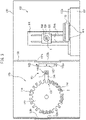
Figure 3 , the horizontal machining center formed by themachine tool 100 comprises atool magazine 120 configured to accommodate a plurality of tools necessary for the process in themachine tool 100, a tool changer configured to change a tool T attached to the end of thespindle 110 of themachine tool 100 with one of the tools accommodated in thetool magazine 120 in accordance with a command from an NC device (not shown) of themachine tool 100. Themachine tool 100, thetool magazine 12 and thetool changer 140 are enclosed by acover 130. In this embodiment, thetool magazine 120 provides a rotating shaft apparatus. - The
cover 130 comprises apartition 132 configured to divide the interior space of the cover into a processing chamber 134 and a tool accommodating chamber 136. Themachine tool 100 is placed in the processing chamber for machining a workpiece, while the tool magazine and thetool changer 140 are placed in the tool accommodating chamber 136. Thepartition 132 defines an opening 132a allowing a tool to be transported between the processing chamber 134 and the tool accommodating chamber 136. Thepartition 132 is provided with ashutter 132b configured to open and close the opening 132a. Thecover 130 defines an opening 138a for allowing an operator to access the tool accommodating chamber 136 to mount tools onto thetool magazine 120 and to remove tools from the tool magazine. The opening 138a is opened and closed by an ATCdoor 138b. New tools are mounted to thetool magazine 120, and used tools are removed from thetool magazine 120 by an operator of themachine tool 100, after opening the ATCdoor 138b of thecover 130, whereby the tools are exchanged. - The
tool magazine 120 comprises abase member 122 in the formed of a circular plate. Thebase member 122 has a plurality ofreceptacles 124 of recesses which open outwardly in the radial directions, and are equally disposed at an angle in the peripheral direction. A tool is held in each of thereceptacles 124 via atool holder 126. Thetool magazine 120 is supported, for rotating within a vertical plane, by a supporting structure such as a frame (not shown) via a rotating shaft 120a which is held horizontally. The rotating shaft 120a is coupled with an output shaft of a servomotor 18 (Figure 1 ) for rotationally driving thetool magazine 120. - The
tool changer 140 is disposed between thetool magazine 120 and themachine tool 100, and provided with a changingarm 142 and ashifter 144. Provided at the either ends of the changingarm 142 aregrippers arm 142 is capable of liner movement, i.e., advancing and retracting along the rotational axis Os of thespindle 110, and rotational movement, i.e., rotating by 90° or 180° within a plane perpendicular to the rotational axis Os of thespindle 110. - The
shifter 144 is configured to horizontally reciprocate between thetool magazine 120 and the changingarm 142. Theshifter 144 receives a tool, which is located at awaiting position 121 of thetool magazine 120, from thetool magazine 120 and transfers the tool to atool handover position 146. Further, theshifter 144 receives a tool at thehandover position 146 from the changingarm 142 and inserts the tool into one of thereceptacles 124 positioned at thewaiting position 121. -
Figure 1 is a block diagram showing an embodiment of the control device for theservomotor 18 for driving thetool magazine 120. Thecontrol device 10 for theservomotor 18 may be formed, for example, as a part of an NC device (not shown) for themachine tool 100, and comprises a reading and interpretingsection 12, aninterpolating section 14, a servo-controllingsection 16, an unbalancetorque calculating section 22, an unbalancetorque canceling section 24 and an acceleration/decelerationparameter modifying section 28. - The
control device 10 performs a feedback control similar to typical servo-controlling devices. The reading and interpretingsection 12 reads and interprets an NC program which is input through input means 11, for example a network means such as a LAN, a key board, or a touch panel, andoutputs operation commands 12a to the interpolatingsection 14. Theoperation commands 12a include a movement command for moving thereceptacle 124, into which a tool need for the next process is inserted, to the waiting position. The interpolatingsection 14 interpolates the receivedoperation commands 12a based on a interpolative function, and outputs position commands (pulse position commands) 14a suitable for a predetermined rotational velocity to the servo-controllingsection 16. The servo-controllingsection 16 outputs, based on the receivedposition commands 14, an electric current value as a torque command for rotating thetool magazine 120 to theservomotor 18. The rotational position andvelocity 20a of theservomotor 18 are fed back to the servo-controllingsection 16 from an encoder (rotary encoder) 20 of theservomotor 18. - During the above described replacement of the tools, an operator does not consider the positions of the tools in the peripheral direction of the
tool magazine 120, whereby the tools are not distributed evenly in the peripheral direction of thetool magazine 120, and the tools are often mounted biasedly in the peripheral direction of thetool magazine 120 as shown inFigure 3 . When the tools are unevenly distributed, a torque or moment (hereinafter, referred to as unbalance torque), based on the gravity forces of the tools, is acting on thetool magazine 120. - With reference to
Figures 4-7 , the unbalance torque will be described below. -
Figure 4 is a graph showing the velocity (dotted line) of a rotating body, such as thetool magazine 120, configured to rotate about a rotational axis, and the torque (thin line) applied to the rotating body, when the rotating body is rotationally driven, wherein an unbalance torque is not acting on the rotating body. In the graph ofFigure 4 , the rotational velocity of the rotating body is increased at a constant acceleration from time t=t0, during which a constant torque is applied to the rotating body. From t=t1 to t=t2, the rotating body rotates at a constant velocity, during which a torque τ=τ', corresponding to the frictional force (the Coulomb's force and the viscosity of the lubricant) acting on the rotating body is applied. From t=t2 to t=t3, the rotational velocity is decreased at a constant deceleration, during which a negative torque is applied to the rotating body. - When the
tool magazine 120, to which the tools are attached unevenly in the peripheral direction (Figure 3 ), rotates about a horizontal or an inclined rotational axis so that the gravity force is affected, Unbalance torque is acting on the rotating body. For example, when the rotating body is rotationally driven with the velocity variation, as shown inFigure 4 , the torque, actually applied to the rotating body, is increased or decreased as a whole, as shown inFigure 5 in which the torque is not constant between t=t1 to t=t2, during which the velocity is constant and changed (increased) with the time. If such an unbalance torque is not considered, then problems that sufficient velocity is not obtained or the velocity is changed suddenly will be raised, even if theservomotor 18 is feedback-controlled. - In order to solve such problems, according to the embodiment, the unbalance
torque calculating section 22 receives torque command or electriccurrent value 16b, output from the servo-controllingsection 16, andposition information 20b output from theencoder 20, and calculates the unbalance torque acting on thetool magazine 120. Then, the unbalancetorque canceling section 24 receives theunbalance torque 22a, calculated by the unbalancetoque calculating section 22, the torque command or the electriccurrent value 16c from the servo-controllingsection 16, and the position andvelocity information 20c from theencoder 20, and corrects thetorque 16b so as to cancel the unbalance torque. The acceleration/decelerationparameter modifying section 28 receives, from the unbalancesection canceling section 24, thetorque 24a corrected by the unbalancetorque canceling section 24 and the position andvelocity information 20c which the unbalancetorque canceling section 24 has received from theencoder 20, and calculates the moment of inertia of thetool magazine 120 based on the correctedtorque 24a. The acceleration/deceleration modifying section 28 receives the moment of inertia of thetool magazine 120 from the moment ofinertia calculating section 26, and outputs acceleration/deceleration parameter to the servo-controllingsection 16, after modifying (correcting) the acceleration/deceleration parameter, whereby the electriccurrent value 16a, output from the servo-controllingsection 16 to theservomotor 18, is optimized. Further, thecontrol device 10 may be provided with analarm presenting section 30 configured to present acoustic or visual alarm or caution when the unbalance torque calculated by the unbalancetorque calculating section 22 exceeds a predetermined upper limit. - With reference to
Figures 6 and 7 , the method for measuring and calculating the unbalance performed by the unbalancetorque calculating section 22 will be described below.Figure 5 is a schematic illustration of thetool magazine 120, wherein the filled circles denote ones of thereceptacles 124 of thetool magazine 120 in which tools are held.Figure 7 shows the changes in the unbalance torque relative to the rotational angle of the tool magazine. - As shown in
figure 6 , when the tools T are attached to thetool magazine 120 unevenly in the peripheral direction, the center of gravity of the tool magazine is moved to a position deviated by length L from the center of thebase member 122 of thetool magazine 120. Accordingly, if the tools are unevenly distributed in the peripheral direction of thebase member 122, the center of the gravity is deviated from the center, whereby a load torque is applied to the tool magazine to rotate the tool magazine. Here, the gravity force acting on thetool magazine 120, including thebase member 122 and the tools attached to thebase member 122, is assumed to be G. The rotational angle of thetool magazine 120 is assumed to be θ=0°, when the center of gravity is at three o'clock relative to the center of thetool magazine 120. When the rotational angle is θ=0° or θ=180°, the stopping load torque T0 will become the maximum, i.e., T0=GL. - Here,
- T1: Unbalance torque
- L: Length from the center of
tool magazine 120 to the center of gravity. - Referring to
Figure 6 , the stopping load torque T is generally presented by the following equation.
- Therefore, when stopped at a position rotated by θ=θ1 from the rotational angle of θ=0°, the stopping load torque T1 applied to the
tool magazine 120 can be calculated by the following equation.
- When
tool magazine 120 is stopped at a position further rotated 90° from the rotational position θ=φ, the stopping load torque T2 applied to thetool magazine 120 can be calculated by the following equation.
- Further, the formula of triangular function gives the following equation.

- Therefore, based on the equations (1)-(4), the unbalance torque T0 or the maximum stopping load torque can be calculated from the following equation.

- Furthermore, from equation (2), the initial phase θ1 is obtained from the following equation.

- In this connection, it should be noted that although the stopping load torque is measure at two measuring points which are apart from each other by 90° in the peripheral direction about the center of the rotating shaft 120a in the present embodiment, the invention is not limited to this configuration. The measuring points may be apart from each other by an angle greater than 90°. Further, the measuring point is not limited to a single point, and the measurement may be carried out at a the stopping load torque may be measured at a plurality of points.
- With reference to the flow chart show in
Figure 8 , the method for measuring and calculating the unbalance torque will be described more concretely below. - The unbalance torque may be measured and calculated when tools are replaced as described above. When the operator of the
machine tool 100 starts to replace the tools (Step S10), the tool accommodating chamber 136 is put into a state allowing manual intervention by the operator (Step S12). This may be carried out by depressing a press button (not shown) provided on an operating panel (not shown) of themachine tool 100, whereby an automatic movement of themachine tool 100, which is not anticipated by the operator, is inhibited when the operator accesses thetool magazine 120. - Then, after the operator opens the
ATC door 138a (Step S14), the operator accesses thetool magazine 120 in order to replace the tools (Step S16). Then, after theATC door 138a is closed (Step S18), the intervention to the NC device is disengaged (Step S20) by depressing a press button provided on the operating panel (not shown) of themachine tool 100. - After the intervention to the NC device is disengaged, the NC device reads a program for measuring the unbalance torque of the
tool magazine 120 to start the measurement of the unbalance torque. The unbalancetorque calculating section 22 reads the electriccurrent value 16b presently supplied to theservomotor 18, which keeps thetool magazine 120 stopped (Step S22). The torque (T1) (stopping load torque) necessary to keep the tool magazine stopped against the unbalance torque can be obtained based on the read electriccurrent value 16b. - Then, after the
tool magazine 120 is rotated by 90° (Step S24), the electriccurrent value 16b, necessary to keep thetool magazine 120 at the rotational position, is read from the servo-controlling section 16 (Step S26). The torque (T2) (stopping load torque) necessary to keep the tool magazine stopped against the unbalance torque can be obtained based on the read electriccurrent value 16b. - Then, at Step S28, the unbalance
torque calculating section 22 calculates the maximum unbalance toque T0, from equation (6), based on the two torque values (T1, T2) and equation (5), and the initial phase θ1. - Then, the
torque canceling section 24 calculates, based on unbalance torque T0 calculated by the unbalancetoque calculating section 22, the initial phase θ1 and the position information read from theencoder 20, the stopping load torque T from following equation (7), when thetool magazine 120 is at an angular position θ.
- The unbalance
torque canceling section 24 further receives the electric current value or thetorque value 16c, supplied to theservomotor 18 of thetool magazine 120, from the servo-controllingsection 16, and calculates torque τ by subtracting the unbalance torque T0 therefrom. - Furthermore, at Step S28, the moment of
inertia calculating section 26 calculates total moment of inertia J of thetool magazine 120, including thebase member 122 and the tools attached to thebase member 122, based on the following method. - Following equation (8) presents the relation between the torque τ (load torque on motion) and the moment of inertia of the
tool magazine 120, when theservomotor 18 rotates.
- Here,
- J: Moment of Inertia
- α: Angular Acceleration
- D: Viscous Damping Coefficient
- V: Angular Velocity
- F: Coulomb Friction Torque u: Unit Vector Indicating the Direction of Velocity
- The angular velocity V and the angular acceleration α can be calculated by the moment of
inertia calculating section 26 based on therotational velocity 20d of theservomotor 18. The unit vector u indicating the direction of velocity is positive when thetool magazine 120 rotates in one of the two rotational directions, and negative when rotating in the other direction. The variables to be obtained, when thetool magazine 120 rotates, are presented by the following equations.


- Accordingly, the values of the torque (load torque on motion) τ, the values of the angular velocity V, the values of the angular acceleration α, and the unit vectors u indicating the velocity directions can be read by the moment of
inertia calculating section 26 at Steps S22 to S26. Then, the moment of inertia J, the viscous damping coefficient D and the coulomb friction torque F of thetool magazine 120 are calculated so that the difference between the sum of squares of the torque τn presented by equation (9), and the sum of squares of the torque τ which is obtained by substituting the variables presented by equations (10), (11) and (12) into equation (8) is the minimum. Accordingly, these variables are calculated by a least squares method. Thus, the moment of inertia J of thetool magazine 120 is calculated by the moment ofinertia calculating section 26. The moment of inertia J, calculated by the moment ofinertia calculating section 26, includes the moment of inertia based on the masses of thebase member 122 of thetool magazine 120 and the tools mounted to thetool magazine 120. - Then, at Step S30, it is determined as to whether or not the unbalance torque T0 exceeds a predetermined threshold value Ts. If the unbalance torque T0 exceeds the predetermined threshold value Ts (NO at Step S30), then the acceleration/deceleration
parameter modifying section 28 maximizes the acceleration/deceleration parameter, outputs it to the servo-controllingsection 16, and outputs a command to thealarm presenting section 30 to present acoustic or visual alarm or caution indicating that the unbalance torque T0 exceeds the predetermined threshold value. The acceleration/deceleration parameter includes the acceleration or gain. - If the unbalance torque does not exceeds the predetermined threshold value Ts (YES at Step S30), then the acceleration/deceleration
parameter modifying section 28 outputs modified acceleration/deceleration parameter to the servo-controllingsection 16. The modification of the acceleration/deceleration parameter is performed similar to the modification which is performed when the moment of inertia is increased, wherein the increase in the value of the unbalance torque T0 of thetool magazine 120 is interpreted into the increase in the moment of inertia of thetool magazine 120. In particular, moment of inertial correction values are associated with the respective values of the unbalance torque T0, and stored in the form of a table in a memory region of thecontrol device 10, whereby the moment of inertial correction value is read from the table according to the value of the unbalance torque T0. The moment of inertial correction values to be added to the moment of inertia according to the increase in the unbalance torque T0 may be precedingly and experimentally obtained, and a table may be created and stored so as to associate the values of the unbalance torque T0 with the moment of inertia correction values. The acceleration/deceleration parameters are associated with respective values obtained by adding the moment of inertial correction values to the moments of inertia, and stored in the form of a table in a memory region of thecontrol device 10, whereby the acceleration/deceleration parameter is read from the table according to the value obtained by adding the moment of inertial correction value to the moment of inertia. The acceleration/deceleration parameter is modified according to the values of the moment of inertia and the unbalance torque T0, whereby enabling more quick acceleration/deceleration, when the moment of inertia and the unbalance toque T0 are small, and whereby thetool magazine 120 can be positioned in a shorter time. - In the above described embodiment, while the motor controlling method according to the invention controls the drive motor for the tool magazine, the invention is not limited to this, and can be applied to a rotary feed shaft rotating about a horizontal or inclined rotational axis. For example, in a machine tool shown in
Figure 2 , the C-axis rotary table 118 may be controlled by the method of the invention. In this case, the center of gravity of theworkpiece 116 attached to the C-axis table 118 is generally deviated from the rotational axis of the C-axis feed shaft, and therefore the present invention can be applied to the axis feed shaft. -
- 10
- Control Device
- 18
- Servomotor
- 20
- Encoder
- 20a
- Rotating Velocity
- 20b
- Position Information
- 20c
- Velocity Information and Position Information
- 20d
- Rotating Velocity
- 22
- Unbalance Torque Calculating Section
- 22a
- Unbalance Torque
- 24
- Unbalance Torque Canceling Section
- 100
- Machine Tool
- 120
- Tool Magazine
- 120a
- Rotating Shaft
- 136
- Tool Accommodating Chamber
Claims (7)
- A method of controlling a motor of a rotating shaft apparatus (120a) configured to rotate about a horizontal or inclined rotational axis, characterized by the steps of:positioning the rotating shaft apparatus (120a) at at least two rotational positions;measuring a stopping load torque acting on the rotating shaft apparatus (120a) at each of the rotational positions;calculating an unbalance torque based on the measured stopping load torques; andcontrolling the motor of the rotating shaft apparatus (120a) based on the unbalance torque.
- The method of controlling a motor according to claim 1, wherein the rotational positions are two points which are apart from each other by 90° around the rotational axis, and wherein the unbalance torque is calculated by the square root of sum of squares of the stopping load torques at the two points.
- The method of controlling a motor according to claim 1 or 2, wherein the rotational position is determined based on the measured stopping load torque, wherein the stopping load torque is calculated at each rotational phase of the rotating shaft device, and wherein the unbalance torque at each rotational phase is subtracted from the measured load torque on motion, whereby the moment of inertia of the rotating shaft apparatus (120a) is calculated based on the load torque on motion excluding the unbalance torque.
- The method of controlling a motor according to claim 3, wherein a moment of inertia correction value, which is precedingly set, is added to the calculated motion of inertia, according to the value of the unbalance torque, and wherein the acceleration/deceleration parameter of the rotating shaft apparatus (120a) is determined based on the motion of inertia to which the correction value is added.
- The method of controlling a motor according to claim 1, wherein an alarm or caution is generated when the unbalance torque exceeds a predetermined threshold value.
- An apparatus for controlling a motor of a rotating shaft apparatus (120a) configured to rotate about a horizontal or inclined rotational axis, the apparatus comprising:means for positioning the rotating shaft apparatus (120a) at at least two rotational positions;means for measuring a stopping load torque acting on the rotating shaft apparatus (120a) at each of the rotational positions;a calculating Z section (22) configured to calculate an unbalance torque based on the measured stopping load torques; anda control device (10) configured to control the motor of the rotating shaft apparatus (120a) based on the unbalance torque.
- A machine tool (100) comprising a tool magazine (120) controlled by the apparatus according to claim 6.
Applications Claiming Priority (1)
| Application Number | Priority Date | Filing Date | Title |
|---|---|---|---|
| PCT/JP2015/055899 WO2016135958A1 (en) | 2015-02-27 | 2015-02-27 | Motor control method and control device, and machine tool provided with tool magazine |
Publications (3)
| Publication Number | Publication Date |
|---|---|
| EP3263275A1 EP3263275A1 (en) | 2018-01-03 |
| EP3263275A4 EP3263275A4 (en) | 2018-11-21 |
| EP3263275B1 true EP3263275B1 (en) | 2022-04-27 |
Family
ID=56788063
Family Applications (1)
| Application Number | Title | Priority Date | Filing Date |
|---|---|---|---|
| EP15883252.7A Active EP3263275B1 (en) | 2015-02-27 | 2015-02-27 | Motor control method and control device, and machine tool provided with tool magazine |
Country Status (5)
| Country | Link |
|---|---|
| US (1) | US10324449B2 (en) |
| EP (1) | EP3263275B1 (en) |
| JP (1) | JP6407402B2 (en) |
| CN (1) | CN107206559B (en) |
| WO (1) | WO2016135958A1 (en) |
Families Citing this family (15)
| Publication number | Priority date | Publication date | Assignee | Title |
|---|---|---|---|---|
| DE102016209833B4 (en) * | 2016-06-03 | 2019-10-31 | Volkswagen Aktiengesellschaft | Method and device for determining a driver's manual torque on a steering wheel of a vehicle |
| JP6599016B2 (en) * | 2016-09-09 | 2019-10-30 | 株式会社牧野フライス製作所 | Machine Tools |
| CN109689289B (en) * | 2016-09-09 | 2021-11-30 | 株式会社牧野铣床制作所 | Machine tool |
| JP6877729B2 (en) * | 2016-11-10 | 2021-05-26 | 中村留精密工業株式会社 | Parameter adjustment system for servo motor control device in machine tools |
| TWI744414B (en) * | 2016-11-16 | 2021-11-01 | 日商報國股份有限公司 | Automatic tool changer |
| JP6836143B2 (en) * | 2016-12-27 | 2021-02-24 | 株式会社ジェイテクト | Machine Tools |
| JP6856469B2 (en) | 2017-07-19 | 2021-04-07 | ファナック株式会社 | Servo motor controller |
| DE102017116869A1 (en) * | 2017-07-26 | 2019-01-31 | Chiron-Werke Gmbh & Co. Kg | Device for determining highly loaded positions in a machine tool |
| US10935954B2 (en) * | 2018-05-17 | 2021-03-02 | Arcus Technology, Inc. | Motion system health management using existing servo drive variables |
| JP7036071B2 (en) * | 2019-03-18 | 2022-03-15 | ブラザー工業株式会社 | Numerical control device, numerical control program, and storage device that stores the numerical control program |
| CN112536643B (en) * | 2019-09-23 | 2023-01-24 | 富鼎电子科技(嘉善)有限公司 | Machine health monitoring method and device and computer readable storage medium |
| CN111360572B (en) * | 2020-03-31 | 2021-11-19 | 新代科技(苏州)有限公司 | Tool magazine control system and control method thereof |
| CN113742880A (en) * | 2020-05-27 | 2021-12-03 | 台达电子工业股份有限公司 | Method for predicting and compensating friction force of feeding system and computer readable storage medium |
| TW202147181A (en) * | 2020-06-10 | 2021-12-16 | 淡江大學 | Three-finger mechanical gripper system and training method thereof |
| CN112643377A (en) * | 2020-12-08 | 2021-04-13 | 常州市利凯数控科技有限公司 | Stable in structure's rotatory tool changing device |
Family Cites Families (14)
| Publication number | Priority date | Publication date | Assignee | Title |
|---|---|---|---|---|
| JPS5853733A (en) | 1981-09-28 | 1983-03-30 | Ricoh Co Ltd | Measuring method for static unbalance amount |
| JP2722004B2 (en) | 1989-10-28 | 1998-03-04 | オ−クマ株式会社 | Adaptive control method of turret turning speed |
| JP2001062672A (en) | 1999-08-31 | 2001-03-13 | Okuma Corp | Numerical control device |
| JP2002046042A (en) * | 2000-08-02 | 2002-02-12 | Murata Mach Ltd | Machine tool |
| CN100420928C (en) * | 2003-12-30 | 2008-09-24 | 丰田自动车株式会社 | Unbalance measurement method and device for long shaft rotator |
| JP4655485B2 (en) | 2004-02-13 | 2011-03-23 | ブラザー工業株式会社 | Conveying apparatus, conveying acceleration determining method for the conveying apparatus, and computer program |
| JP2007016288A (en) * | 2005-07-08 | 2007-01-25 | Toyota Motor Corp | Method for manufacturing sliding member coated with bearing material and sliding member coated with bearing material |
| US7551411B2 (en) * | 2005-10-12 | 2009-06-23 | Black & Decker Inc. | Control and protection methodologies for a motor control module |
| JP4767925B2 (en) * | 2007-08-03 | 2011-09-07 | ファナック株式会社 | Machine Tools |
| NZ588159A (en) * | 2010-09-23 | 2014-01-31 | Powerbyproxi Ltd | A contactless power transfer system |
| JP5003832B1 (en) * | 2011-03-08 | 2012-08-15 | 株式会社安川電機 | Motor control device and motor control method |
| JP5291820B2 (en) * | 2011-05-26 | 2013-09-18 | ファナック株式会社 | Oscillator control device and machine tool |
| JP5751433B2 (en) * | 2013-02-06 | 2015-07-22 | 株式会社安川電機 | Motor control device and motor control method |
| CN203944859U (en) * | 2014-07-14 | 2014-11-19 | 林宇 | Novel cutter tower |
-
2015
- 2015-02-27 EP EP15883252.7A patent/EP3263275B1/en active Active
- 2015-02-27 US US15/553,754 patent/US10324449B2/en active Active
- 2015-02-27 CN CN201580074519.7A patent/CN107206559B/en active Active
- 2015-02-27 WO PCT/JP2015/055899 patent/WO2016135958A1/en active Application Filing
- 2015-02-27 JP JP2017501804A patent/JP6407402B2/en active Active
Also Published As
| Publication number | Publication date |
|---|---|
| US10324449B2 (en) | 2019-06-18 |
| CN107206559B (en) | 2020-04-28 |
| JP6407402B2 (en) | 2018-10-17 |
| JPWO2016135958A1 (en) | 2017-09-28 |
| EP3263275A1 (en) | 2018-01-03 |
| EP3263275A4 (en) | 2018-11-21 |
| CN107206559A (en) | 2017-09-26 |
| WO2016135958A1 (en) | 2016-09-01 |
| US20180032052A1 (en) | 2018-02-01 |
Similar Documents
| Publication | Publication Date | Title |
|---|---|---|
| EP3263275B1 (en) | Motor control method and control device, and machine tool provided with tool magazine | |
| EP2058082B1 (en) | Machine tool | |
| EP1704956B1 (en) | Welding system and consumable electrode welding method | |
| JP4323542B2 (en) | Motor control device with learning control function | |
| EP3118710B1 (en) | Feed shaft control method and numerical control work device | |
| JP6107306B2 (en) | Numerical control apparatus and drive control method | |
| JP5851910B2 (en) | Machine tool control method and machine tool | |
| JP2016189039A (en) | Numerical control device and control method | |
| JP7042925B2 (en) | Work automatic carrier | |
| JPH0452908A (en) | Tool deformation correcting system | |
| US9645554B2 (en) | Parameter setting method and parameter setting apparatus for positioning apparatus, and positioning apparatus provided with the parameter setting apparatus | |
| CN211554727U (en) | Machine tool, machining system, and management system | |
| US9740196B2 (en) | Numerical controller for controlling drilling operation | |
| JPH1063339A (en) | Controller of numerical value control machine tool | |
| JPH06289917A (en) | Servo motor control method by estimated disturbance load torque | |
| JP7167811B2 (en) | Machine tool, information processing method and computer program | |
| US11003171B2 (en) | Parameter setting device, system, and parameter setting method | |
| JP2020181424A (en) | Numerical controller and machine tool | |
| JP2024034256A (en) | Numerical control device, identification method, and identification program | |
| JPS63123654A (en) | Vibration preventive device | |
| KR20080058530A (en) | Numerical control system and method in a work machine | |
| JP2022020269A (en) | Control apparatus, machine tool, control method, and control program | |
| CN112334748A (en) | Method for determining the mass and the position of the center of gravity of a load in a mobile system, in particular a machine tool | |
| JP3181360U (en) | Machine Tools | |
| FI109410B (en) | Method and equipment in sheet metal working machine |
Legal Events
| Date | Code | Title | Description |
|---|---|---|---|
| STAA | Information on the status of an ep patent application or granted ep patent |
Free format text: STATUS: THE INTERNATIONAL PUBLICATION HAS BEEN MADE |
|
| PUAI | Public reference made under article 153(3) epc to a published international application that has entered the european phase |
Free format text: ORIGINAL CODE: 0009012 |
|
| STAA | Information on the status of an ep patent application or granted ep patent |
Free format text: STATUS: REQUEST FOR EXAMINATION WAS MADE |
|
| 17P | Request for examination filed |
Effective date: 20170906 |
|
| AK | Designated contracting states |
Kind code of ref document: A1 Designated state(s): AL AT BE BG CH CY CZ DE DK EE ES FI FR GB GR HR HU IE IS IT LI LT LU LV MC MK MT NL NO PL PT RO RS SE SI SK SM TR |
|
| AX | Request for extension of the european patent |
Extension state: BA ME |
|
| DAX | Request for extension of the european patent (deleted) | ||
| A4 | Supplementary search report drawn up and despatched |
Effective date: 20181024 |
|
| RIC1 | Information provided on ipc code assigned before grant |
Ipc: G05B 19/416 20060101ALI20181018BHEP Ipc: B23Q 3/157 20060101AFI20181018BHEP Ipc: B23Q 17/00 20060101ALI20181018BHEP Ipc: B23Q 16/02 20060101ALI20181018BHEP Ipc: B23Q 3/155 20060101ALI20181018BHEP Ipc: G05B 19/404 20060101ALI20181018BHEP Ipc: G01M 1/10 20060101ALI20181018BHEP Ipc: G01M 1/14 20060101ALI20181018BHEP Ipc: B23Q 5/34 20060101ALI20181018BHEP Ipc: B23Q 11/00 20060101ALI20181018BHEP |
|
| STAA | Information on the status of an ep patent application or granted ep patent |
Free format text: STATUS: EXAMINATION IS IN PROGRESS |
|
| 17Q | First examination report despatched |
Effective date: 20210219 |
|
| GRAP | Despatch of communication of intention to grant a patent |
Free format text: ORIGINAL CODE: EPIDOSNIGR1 |
|
| STAA | Information on the status of an ep patent application or granted ep patent |
Free format text: STATUS: GRANT OF PATENT IS INTENDED |
|
| INTG | Intention to grant announced |
Effective date: 20211029 |
|
| GRAS | Grant fee paid |
Free format text: ORIGINAL CODE: EPIDOSNIGR3 |
|
| GRAA | (expected) grant |
Free format text: ORIGINAL CODE: 0009210 |
|
| STAA | Information on the status of an ep patent application or granted ep patent |
Free format text: STATUS: THE PATENT HAS BEEN GRANTED |
|
| AK | Designated contracting states |
Kind code of ref document: B1 Designated state(s): AL AT BE BG CH CY CZ DE DK EE ES FI FR GB GR HR HU IE IS IT LI LT LU LV MC MK MT NL NO PL PT RO RS SE SI SK SM TR |
|
| REG | Reference to a national code |
Ref country code: GB Ref legal event code: FG4D |
|
| REG | Reference to a national code |
Ref country code: CH Ref legal event code: EP |
|
| REG | Reference to a national code |
Ref country code: AT Ref legal event code: REF Ref document number: 1486565 Country of ref document: AT Kind code of ref document: T Effective date: 20220515 |
|
| REG | Reference to a national code |
Ref country code: DE Ref legal event code: R096 Ref document number: 602015078584 Country of ref document: DE |
|
| REG | Reference to a national code |
Ref country code: IE Ref legal event code: FG4D |
|
| REG | Reference to a national code |
Ref country code: LT Ref legal event code: MG9D |
|
| REG | Reference to a national code |
Ref country code: NL Ref legal event code: MP Effective date: 20220427 |
|
| REG | Reference to a national code |
Ref country code: AT Ref legal event code: MK05 Ref document number: 1486565 Country of ref document: AT Kind code of ref document: T Effective date: 20220427 |
|
| PG25 | Lapsed in a contracting state [announced via postgrant information from national office to epo] |
Ref country code: NL Free format text: LAPSE BECAUSE OF FAILURE TO SUBMIT A TRANSLATION OF THE DESCRIPTION OR TO PAY THE FEE WITHIN THE PRESCRIBED TIME-LIMIT Effective date: 20220427 |
|
| PG25 | Lapsed in a contracting state [announced via postgrant information from national office to epo] |
Ref country code: SE Free format text: LAPSE BECAUSE OF FAILURE TO SUBMIT A TRANSLATION OF THE DESCRIPTION OR TO PAY THE FEE WITHIN THE PRESCRIBED TIME-LIMIT Effective date: 20220427 Ref country code: PT Free format text: LAPSE BECAUSE OF FAILURE TO SUBMIT A TRANSLATION OF THE DESCRIPTION OR TO PAY THE FEE WITHIN THE PRESCRIBED TIME-LIMIT Effective date: 20220829 Ref country code: NO Free format text: LAPSE BECAUSE OF FAILURE TO SUBMIT A TRANSLATION OF THE DESCRIPTION OR TO PAY THE FEE WITHIN THE PRESCRIBED TIME-LIMIT Effective date: 20220727 Ref country code: LT Free format text: LAPSE BECAUSE OF FAILURE TO SUBMIT A TRANSLATION OF THE DESCRIPTION OR TO PAY THE FEE WITHIN THE PRESCRIBED TIME-LIMIT Effective date: 20220427 Ref country code: HR Free format text: LAPSE BECAUSE OF FAILURE TO SUBMIT A TRANSLATION OF THE DESCRIPTION OR TO PAY THE FEE WITHIN THE PRESCRIBED TIME-LIMIT Effective date: 20220427 Ref country code: GR Free format text: LAPSE BECAUSE OF FAILURE TO SUBMIT A TRANSLATION OF THE DESCRIPTION OR TO PAY THE FEE WITHIN THE PRESCRIBED TIME-LIMIT Effective date: 20220728 Ref country code: FI Free format text: LAPSE BECAUSE OF FAILURE TO SUBMIT A TRANSLATION OF THE DESCRIPTION OR TO PAY THE FEE WITHIN THE PRESCRIBED TIME-LIMIT Effective date: 20220427 Ref country code: ES Free format text: LAPSE BECAUSE OF FAILURE TO SUBMIT A TRANSLATION OF THE DESCRIPTION OR TO PAY THE FEE WITHIN THE PRESCRIBED TIME-LIMIT Effective date: 20220427 Ref country code: BG Free format text: LAPSE BECAUSE OF FAILURE TO SUBMIT A TRANSLATION OF THE DESCRIPTION OR TO PAY THE FEE WITHIN THE PRESCRIBED TIME-LIMIT Effective date: 20220727 Ref country code: AT Free format text: LAPSE BECAUSE OF FAILURE TO SUBMIT A TRANSLATION OF THE DESCRIPTION OR TO PAY THE FEE WITHIN THE PRESCRIBED TIME-LIMIT Effective date: 20220427 |
|
| PG25 | Lapsed in a contracting state [announced via postgrant information from national office to epo] |
Ref country code: RS Free format text: LAPSE BECAUSE OF FAILURE TO SUBMIT A TRANSLATION OF THE DESCRIPTION OR TO PAY THE FEE WITHIN THE PRESCRIBED TIME-LIMIT Effective date: 20220427 Ref country code: PL Free format text: LAPSE BECAUSE OF FAILURE TO SUBMIT A TRANSLATION OF THE DESCRIPTION OR TO PAY THE FEE WITHIN THE PRESCRIBED TIME-LIMIT Effective date: 20220427 Ref country code: LV Free format text: LAPSE BECAUSE OF FAILURE TO SUBMIT A TRANSLATION OF THE DESCRIPTION OR TO PAY THE FEE WITHIN THE PRESCRIBED TIME-LIMIT Effective date: 20220427 Ref country code: IS Free format text: LAPSE BECAUSE OF FAILURE TO SUBMIT A TRANSLATION OF THE DESCRIPTION OR TO PAY THE FEE WITHIN THE PRESCRIBED TIME-LIMIT Effective date: 20220827 |
|
| REG | Reference to a national code |
Ref country code: DE Ref legal event code: R097 Ref document number: 602015078584 Country of ref document: DE |
|
| PG25 | Lapsed in a contracting state [announced via postgrant information from national office to epo] |
Ref country code: SM Free format text: LAPSE BECAUSE OF FAILURE TO SUBMIT A TRANSLATION OF THE DESCRIPTION OR TO PAY THE FEE WITHIN THE PRESCRIBED TIME-LIMIT Effective date: 20220427 Ref country code: SK Free format text: LAPSE BECAUSE OF FAILURE TO SUBMIT A TRANSLATION OF THE DESCRIPTION OR TO PAY THE FEE WITHIN THE PRESCRIBED TIME-LIMIT Effective date: 20220427 Ref country code: RO Free format text: LAPSE BECAUSE OF FAILURE TO SUBMIT A TRANSLATION OF THE DESCRIPTION OR TO PAY THE FEE WITHIN THE PRESCRIBED TIME-LIMIT Effective date: 20220427 Ref country code: EE Free format text: LAPSE BECAUSE OF FAILURE TO SUBMIT A TRANSLATION OF THE DESCRIPTION OR TO PAY THE FEE WITHIN THE PRESCRIBED TIME-LIMIT Effective date: 20220427 Ref country code: DK Free format text: LAPSE BECAUSE OF FAILURE TO SUBMIT A TRANSLATION OF THE DESCRIPTION OR TO PAY THE FEE WITHIN THE PRESCRIBED TIME-LIMIT Effective date: 20220427 Ref country code: CZ Free format text: LAPSE BECAUSE OF FAILURE TO SUBMIT A TRANSLATION OF THE DESCRIPTION OR TO PAY THE FEE WITHIN THE PRESCRIBED TIME-LIMIT Effective date: 20220427 |
|
| PLBE | No opposition filed within time limit |
Free format text: ORIGINAL CODE: 0009261 |
|
| STAA | Information on the status of an ep patent application or granted ep patent |
Free format text: STATUS: NO OPPOSITION FILED WITHIN TIME LIMIT |
|
| PG25 | Lapsed in a contracting state [announced via postgrant information from national office to epo] |
Ref country code: AL Free format text: LAPSE BECAUSE OF FAILURE TO SUBMIT A TRANSLATION OF THE DESCRIPTION OR TO PAY THE FEE WITHIN THE PRESCRIBED TIME-LIMIT Effective date: 20220427 |
|
| 26N | No opposition filed |
Effective date: 20230130 |
|
| PGFP | Annual fee paid to national office [announced via postgrant information from national office to epo] |
Ref country code: FR Payment date: 20230127 Year of fee payment: 9 |
|
| PG25 | Lapsed in a contracting state [announced via postgrant information from national office to epo] |
Ref country code: SI Free format text: LAPSE BECAUSE OF FAILURE TO SUBMIT A TRANSLATION OF THE DESCRIPTION OR TO PAY THE FEE WITHIN THE PRESCRIBED TIME-LIMIT Effective date: 20220427 |
|
| PGFP | Annual fee paid to national office [announced via postgrant information from national office to epo] |
Ref country code: IT Payment date: 20230207 Year of fee payment: 9 Ref country code: GB Payment date: 20230210 Year of fee payment: 9 Ref country code: DE Payment date: 20230223 Year of fee payment: 9 |
|
| PG25 | Lapsed in a contracting state [announced via postgrant information from national office to epo] |
Ref country code: MC Free format text: LAPSE BECAUSE OF FAILURE TO SUBMIT A TRANSLATION OF THE DESCRIPTION OR TO PAY THE FEE WITHIN THE PRESCRIBED TIME-LIMIT Effective date: 20220427 |
|
| REG | Reference to a national code |
Ref country code: CH Ref legal event code: PL |
|
| REG | Reference to a national code |
Ref country code: BE Ref legal event code: MM Effective date: 20230228 |
|
| PG25 | Lapsed in a contracting state [announced via postgrant information from national office to epo] |
Ref country code: LU Free format text: LAPSE BECAUSE OF NON-PAYMENT OF DUE FEES Effective date: 20230227 Ref country code: LI Free format text: LAPSE BECAUSE OF NON-PAYMENT OF DUE FEES Effective date: 20230228 Ref country code: CH Free format text: LAPSE BECAUSE OF NON-PAYMENT OF DUE FEES Effective date: 20230228 |
|
| REG | Reference to a national code |
Ref country code: IE Ref legal event code: MM4A |
|
| PG25 | Lapsed in a contracting state [announced via postgrant information from national office to epo] |
Ref country code: IE Free format text: LAPSE BECAUSE OF NON-PAYMENT OF DUE FEES Effective date: 20230227 |
|
| PG25 | Lapsed in a contracting state [announced via postgrant information from national office to epo] |
Ref country code: BE Free format text: LAPSE BECAUSE OF NON-PAYMENT OF DUE FEES Effective date: 20230228 |