WO2016133179A1 - コイル、ステータおよびモータ - Google Patents
コイル、ステータおよびモータ Download PDFInfo
- Publication number
- WO2016133179A1 WO2016133179A1 PCT/JP2016/054776 JP2016054776W WO2016133179A1 WO 2016133179 A1 WO2016133179 A1 WO 2016133179A1 JP 2016054776 W JP2016054776 W JP 2016054776W WO 2016133179 A1 WO2016133179 A1 WO 2016133179A1
- Authority
- WO
- WIPO (PCT)
- Prior art keywords
- plate
- annular coil
- coil body
- unit
- annular
- Prior art date
- Legal status (The legal status is an assumption and is not a legal conclusion. Google has not performed a legal analysis and makes no representation as to the accuracy of the status listed.)
- Ceased
Links
Images





Classifications
-
- H—ELECTRICITY
- H01—ELECTRIC ELEMENTS
- H01F—MAGNETS; INDUCTANCES; TRANSFORMERS; SELECTION OF MATERIALS FOR THEIR MAGNETIC PROPERTIES
- H01F5/00—Coils
-
- H—ELECTRICITY
- H02—GENERATION; CONVERSION OR DISTRIBUTION OF ELECTRIC POWER
- H02K—DYNAMO-ELECTRIC MACHINES
- H02K3/00—Details of windings
- H02K3/04—Windings characterised by the conductor shape, form or construction, e.g. with bar conductors
- H02K3/18—Windings for salient poles
Definitions
- the present invention relates to a coil, a stator, and a motor.
- the space factor is a ratio between the cross-sectional area of the stator slot and the coil cross-sectional area disposed in the slot.
- the space factor of the coil it is conceivable to increase the number of turns of the wire forming the coil.
- round wire or rectangular wire there is an upper limit to the number of turns that can be wound in the slot due to the size of the nozzle of the winding machine, winding space, etc., and the space factor above a certain level. It was difficult to realize.
- Patent Document 1 proposes a coil structure for a motor that improves the space factor (line product ratio) of the motor in order to improve the torque density of the motor.
- the coils in the slot are stacked and incorporated in the slots of the stator iron core.
- a slot-to-slot coil is individually joined to one end face and the other end face of the in-slot coil.
- the coil in the slot is a linear member
- the inter-slot coil is a bar-shaped member.
- One end and the other end of the in-slot coil are formed thinner than the thickness of the in-slot coil in order to fit the inter-slot coil.
- an object of the present invention is to provide a coil, a stator, and a motor that can be easily assembled while increasing the space factor of the coil.
- the coil of the present invention is a coil used in a motor that rotates about a central axis extending in the vertical direction, and is a plurality of first units and second units that are arranged in the radial direction around the central axis. And a bridge portion electrically connected to the unit, the unit having a first annular coil body made of a metal plate and a second annular coil body made of a metal plate that overlaps the first annular coil body in the radial direction.
- first annular coil body a part of the annular shape is opened upward in the axial direction of the central axis, and the first one-side opening end on one side in the circumferential direction around the central axis among the opening ends, and the circumferential direction
- a first coil base having a first other-side opening end on the other side, a first one-side terminal extending integrally in the axial direction from one circumferential side of the first one-side opening end, and a first From the one side in the circumferential direction of the opening end on the other side, it extends integrally in the axial direction.
- a second annular coil body wherein a part of the annular shape is opened upward in the axial direction, a second one-side opening end on one circumferential side of the opening ends, and a circumferential direction
- a second coil base having a second other side opening end on the other side, and an axial direction along the first one side opening end integrally from the other circumferential side of the second one side opening end.
- the bridge portion is a substantially plate-shaped metal member that covers the opening of the first coil base and the opening of the second coil base, and one circumferential side of the bridge portion is the first one side of the first unit.
- the terminal portion and the second one-side terminal portion are connected, and the other circumferential side of the bridge portion is connected to a second unit adjacent in the radial direction. Characterized in that connected to the first other-side terminal portions and the second other-side terminal portions that.
- the stator of the present invention is characterized in that a coil is inserted into a plurality of slots. Furthermore, the motor of the present invention includes a stator having a stator coil, and a rotor having a magnet and rotating by energizing the stator coil.
- the present invention can provide a coil, a stator, and a motor that can be easily assembled while increasing the space factor of the coil.
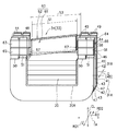
- the longitudinal cross-sectional view along the axial direction CL which shows preferable 1st Embodiment of the motor of this invention.
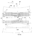
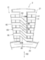
- the top view which shows the structural example of the motor shown in FIG. FIG. 3 is a diagram representatively showing two adjacent slots shown in FIG. 2 and one stator coil region RR.
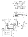
- the perspective view which shows the structural example of 1 set of bridge parts which has electrically connected between the 1st unit and 2nd unit which are shown in FIG. 3, and between the 1st unit and the 2nd unit.
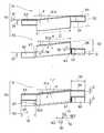
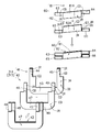
- the exploded view and assembly drawing which show the structural example of a 1st unit and a 2nd unit.
- the perspective view which shows the electrical connection example and insulation example of a 1st unit (2nd unit), and the electrical connection and insulation example of a bridge
- FIG. 1 is a longitudinal sectional view along an axial direction CL showing a first embodiment of the motor of the present invention.
- a motor 1 shown in FIG. 1 includes, for example, a moving body such as an automobile, an electric automobile, an electric assist device, an electric airplane, a multicopter, an industrial device such as a robot, an information recording / reproducing device that rotates an information recording medium, a home appliance, and an office device. It can be mounted on mounting objects in various fields such as medical devices.
- the motor 1 includes a stator 2 and a rotor 3.
- the stator 2 is a stator
- the rotor 3 is a rotor.
- the rotor 3 of the motor 1 is a so-called outer rotor type motor that rotates together with the central shaft 4 along the circumferential direction TA around the stator 2, for example.
- the stator 2 is fixed to, for example, a fixed part of the driving object.
- the rotor 3 is supported by the stator 2 so as to be rotatable about the axial direction CL of the central shaft 4.
- the central axis 4 of the motor 1 is determined.
- a direction parallel to the central axis 4 is described as “axial direction” CL as indicated by a one-dot chain line.
- the direction orthogonal to the axial direction CL is indicated as “radial direction” RD as indicated by an arrow.
- the direction along the arc of the axial direction CL is indicated as “circumferential direction” TA as indicated by an arrow.
- the axial direction CL of the central axis 4 is the vertical direction in the drawing.
- the space factor is the ratio of the total cross-sectional area of the coils arranged in the slots to the cross-sectional area of the slots of the stator 2 in the motor 1.
- the upper part in the central axis direction of the motor 1 is simply referred to as “upper”, and the lower part is simply referred to as “lower”.
- the paper surface side in the drawing is called “front surface”, and the back surface of the paper surface is called “back surface”.
- front side corresponds to the radially outer side
- “rear side” corresponds to the radially inner side.
- the up / down direction, front / back, front / rear directions do not indicate the positional relationship or direction when incorporated in an actual device.
- the motor 1 increases the cross-sectional area of the coil (stator coil) with respect to the slot area of the stator 2. Increasing the space factor means that the area occupied by the coil is larger than the cross-sectional area of the slot.
- the electric resistance value can be lowered. A large current can be flowed by lowering the electric resistance value of the coil, and the motor 1 is small and lightweight, and can increase torque density and obtain high output (high torque). ing.
- FIG. 2 is a plan view showing the structure of the motor shown in FIG. However, in FIG. 2, illustration of the central shaft 4 and the cylindrical holding part 6 shown in FIG. 1 is omitted for simplification of the drawing.
- the stator 2 includes a fixed plate portion 5, a cylindrical holding portion 6, a stator unit 10, a first bearing 11, a second bearing 12, and the like.
- the fixed plate portion 5 is, for example, an electronic substrate on which electronic components for controlling the motor 1 are mounted, but is not particularly limited.
- the 1 has a large-diameter portion 6A and a small-diameter portion 6B.
- the large diameter portion 6A has an upper end opening 6M, and the small diameter portion 6B has a lower end opening 6N.
- the large-diameter portion 6A holds the first bearing 11 therein.
- the small diameter portion 6B holds the second bearing 12 therein.
- the first bearing 11 and the second bearing 12 are, for example, ball bearings.
- the first bearing 11 is a bearing portion at an upper position of the central shaft 4, and the second bearing 12 is a bearing portion at a lower position.
- the first bearing 11 has a larger size than the second bearing 12.
- the inner ring 11B of the first bearing 11 is fixed to the outer peripheral surface of the small diameter portion 4B of the central shaft 4
- the inner ring 12B of the second bearing 12 is fixed to the outer peripheral surface of the small diameter portion 4B of the central shaft 4.
- a fastener 6C for fixing the position of the second bearing 12 is disposed in the small diameter portion 6B.
- a plurality of balls 11C for constituting a bearing are arranged at intervals between the outer ring 11A and the inner ring 11B of the first bearing 11 shown in FIG.
- a plurality of balls 12C are arranged at intervals between the outer ring 12A and the inner ring 12B of the second bearing 12.
- the center shaft 4 is supported by the first bearing 11 and the second bearing 12 so as to be rotatable about the axial direction CL.
- the first bearing 11 and the second bearing 12 are ball bearings, for example.
- the present invention is not limited to this, and other types of bearings such as a sliding bearing and a fluid bearing are used depending on the application and specifications of the motor. Also good.
- stator unit 10 is fixed to the outer peripheral surface 6D of the small-diameter portion 6B of the holding portion 6.
- the stator unit 10 is an armature that generates magnetic flux in accordance with the drive current supplied from the fixed plate portion 5 shown in FIG.
- the rotor 3 shown in FIG. 1 has a central shaft 4, a housing portion 13, and a plurality of driving magnets 14.
- the central shaft 4 has a large diameter portion 4A and a small diameter portion 4B.
- the large-diameter portion 4A is a portion that is attached to an object to be rotated, for example.
- the inner ring 11B of the first bearing 11 and the inner ring 12B of the second bearing 12 are fixed to the outer peripheral surface of the small diameter portion 4B.
- the housing part 13 covers the periphery of the stator unit 10.
- the housing portion 13 is a circular member having a peripheral wall portion 13A, a bottom portion 13B, and a mounting recess 13C.
- the end 4C of the small diameter portion 4B of the central shaft 4 is fixed to the hole 13D of the mounting recess 13C of the housing portion 13 by, for example, press fitting.
- the peripheral wall portion 13 ⁇ / b> A of the housing portion 13 faces the outer periphery of the stator unit 10 in the radial direction RD.
- a plurality of magnets 14 are arranged in the circumferential direction TA at equal intervals on the inner peripheral surface of the peripheral wall portion 13A.
- the N-pole magnetic pole surfaces and the S-pole magnetic pole surfaces of these magnets 14 are alternately arranged in the circumferential direction TA.
- one annular magnet in which N poles and S poles are alternately magnetized in the circumferential direction may be attached to the peripheral wall portion 13 ⁇ / b> A of the housing portion 13. good.
- the number of N poles and S poles of the magnet 14 is not particularly limited and can be arbitrarily selected.
- stator unit 10 of the stator 2 is fixed to the outer peripheral surface 6 ⁇ / b> D of the small diameter portion 6 ⁇ / b> B of the holding portion 6.
- the stator unit 10 is located inside the housing portion 13 and the plurality of magnets 14 in the radial direction.
- the stator unit 10 is arranged with a predetermined gap in the radial direction with respect to the magnet 14.
- the stator unit 10 includes a ring-shaped stator core 20 and a plurality of stator coils 30.
- the coil 30 is called a stator coil because it is arranged not on the rotor 3 side but on the stator 2 side.
- the outer peripheral surface 20A of the stator core 20 is disposed with a gap in the radial direction with respect to the plurality of magnets 14 disposed in the housing portion 13.
- the inner peripheral surface 20 ⁇ / b> B of the stator core 20 is fixed to the outer peripheral surface 6 ⁇ / b> D of the small diameter portion 6 ⁇ / b> B of the cylindrical holding portion 6.
- the stator core 20 is a laminated steel plate in which a plurality of steel plates are laminated along the axial direction CL, for example.
- the stator 2 has a plurality of slots 21.
- the stator core 20 has a plurality of teeth protruding in the radial direction from the stator core 20.
- a coil is wound around the plurality of teeth.
- the plurality of slots 21 are, for example, substantially trapezoidal gaps formed in a direction parallel to the axial direction CL on the paper surface of FIG. That is, each slot 21 is a gap between the teeth. Twelve slots 21 are formed at predetermined angles, for example, every 30 degrees, with the axial direction CL as the center.
- the number of slots 21 formed and the cross-sectional shape are not limited to the example shown in FIG. 2, and can be arbitrarily selected.
- a plurality of sets of stator coils 30 are attached to a plurality of slots 21.
- Each set of stator coils 30 is inserted across two adjacent slots 21 and 21 and fixed to the teeth of the stator core 20.
- 12 sets of stator coils 30 are attached to 12 slots 21.
- the stator coil 30 is inserted across two adjacent slots 21 via an electrical insulating material such as resin.
- FIG. 3 representatively shows the two adjacent slots 21 shown in FIG. 2 and the region RR of one set of stator coils 30.
- FIG. 3 for the convenience of understanding, an intermediate portion of the pair of stator coils 30 is not shown.
- each slot 21 is a substantially trapezoidal through-hole formed by three wall portions 21A, 21B, 21C and two projecting portions 21D.
- one stator coil 30 is inserted and fixed across two adjacent slots 21 and 21.
- one set of stator coils 30 is electrically connected to the first unit 31A and the second unit 31B, and the first unit 31A and the second unit 31B. And a plurality of bridge portions 60 connected to each other.
- One set of stator coils 30 is arranged such that a plurality of sets of first units 31A and second units 31B are stacked in close contact along the radial direction RD.
- the plurality of bridge portions 60 are electrical connection members that electrically connect the adjacent first unit 31A and second unit 31B.
- the bridge portion 60 is a plate-like member having a large cross-sectional area compared to the cross-sectional area of a coil of a wire rod that is normally used so that the space factor of the coil in the slot 21 can be increased as much as possible.
- the set number of the stator coils 30 and the set number of the bridge portions 60 are not limited to, for example, 10 sets, and can be changed according to the required specifications. good.
- first unit 31A, the second unit 31B, and the plurality of bridge portions 60 are electrically connected.
- the first unit 31 ⁇ / b> A and the second unit 31 ⁇ / b> B can be inserted into the slots 21 and 21 in a state where they are closely stacked along the radial direction RD.
- the structure of the stator coil 30 can increase the space factor of the coil in the slot 21 as much as possible, compared with winding a normal winding around the teeth through the slot.
- FIG. 4 shows a set of the first unit 31A and the second unit 31B, which are adjacent to each other shown in FIG. 3, for electrically connecting the first unit 31A and the second unit 31B.
- FIG. 6 is a perspective view showing a structural example of a bridge section 60.
- FIG. 5 is a perspective view showing a structural example of the first unit 31A and the second unit 31B.
- FIG. 6 is a perspective view showing a structural example of one set of bridge portions 60. As shown in FIGS.
- the outer direction of the radial direction RD is indicated by an arrow RD1
- the inner direction of the radial direction RD is indicated by an arrow RD2.
- the axial direction CL, the circumferential direction TA, and the radial direction RD are orthogonal to each other.
- FIGS. 3, 4, and 5 the structure example of the first unit 31 ⁇ / b> A and the second unit 31 ⁇ / b> B will be described, but the structure of the first unit 31 ⁇ / b> A and the second unit 31 ⁇ / b> B is the same. It is. As a result, by making the first unit 31A and the second unit 31B have the same structure, the stator coil can be easily manufactured and the cost can be reduced.
- FIG. 4 shows a first unit 31A and a second unit 31B, and each unit 31A, 31B has a structure as shown in FIG.
- the structure of the first unit 31A will be described as a representative with reference to FIGS. 5 and 4, but the structure of the second unit 31B is also the same.
- the first unit 31 ⁇ / b> A includes a first annular coil body 41 that is a metal plate, and a second annular coil body that is a metal plate that overlaps the first annular coil body 41 in the radial direction RD. 42.
- the first annular coil body 41 or the second annular coil body 42 shown in FIG. 5 has substantially the same shape when viewed from the front. Thereby, since the 1st annular coil main body 41 or the 2nd annular coil main body 42 can be pressed using the metal mold
- the first annular coil body 41 has an opening 33 by opening a part of the ring upward in the axial direction CL.
- the first annular coil body 41 has a first coil base 43.
- the first coil base 43 includes a first one-side opening end 41R on one side in the circumferential direction TA and a first other-side opening end 41T on the other side in the circumferential direction TA.
- the first annular coil body 41 includes a first one-side terminal portion 44 extending from one side in the circumferential direction TA of the first one-side opening end portion 41R toward the axial direction CL, and a first other-side opening end portion. From the one side of the circumferential direction TA of 41T, it has the 1st other side terminal part 45 extended in the axial direction CL integrally.
- the second annular coil body 42 has an opening 34 by opening a part of the ring upward in the axial direction CL.
- the second annular coil body 42 has a second coil base 47.
- the second coil base 47 has a second one-side opening end portion 42R on one side in the circumferential direction TA and a second other-side opening end portion 42T on the other side in the circumferential direction CL.
- the second annular coil body 42 extends from the other side in the circumferential direction TA of the second one-side opening end portion 42R along the first one-side opening end portion 41R, and then extends in the axial direction CL.
- a side terminal portion 48 is provided.
- the second annular coil body 42 extends from the other side in the circumferential direction TA of the second other-side opening end portion 42T integrally along the first other-side opening end portion 41T, and then extends in the axial direction CL.
- a second other side terminal portion 49 is provided.
- the second annular coil body 42 is positioned on the radially outer side (RD1 direction) with respect to the first annular coil body 41 and overlapped.
- the first annular coil body 41 or the second annular coil body 42 having the same thickness D is overlapped along the radial direction RD, the first one-side terminal part 44, the first other-side terminal part 45, and the second one-side terminal
- the part 48 and the second other-side terminal part 49 are structured to be flush with each other in the radial direction RD.
- the first annular coil body 41 and the second annular coil body 42 have substantially the same shape, and are formed of a metal plate having the same thickness D and excellent in conductivity, such as a copper plate or an aluminum plate. .
- a metal plate having the same thickness D and excellent in conductivity, such as a copper plate or an aluminum plate.
- the first annular coil body 41 and the second annular coil body 42 can preferably adopt an ellipse shape, a circular shape, a U shape, a square shape, or the like that can obtain the same effect as that of the present embodiment. .
- the first annular coil main body 41 and the second annular coil main body 42 are preferably made by pressing a material made of the metal plate, for example, using a mold having substantially the same shape. Thereby, the 1st annular coil main body 41 or the 2nd annular coil main body 42 can be made easily and in a short time, and reduction of manufacturing cost can be aimed at.
- the first annular coil body 41 and the second annular coil body 42 have openings 33 and 34 that are partially opened, and are preferably formed in a substantially U shape. Since the first annular coil body 41 and the second annular coil body 42 have the same shape in plan view, the first annular coil body 41 and the second annular coil body 42 are U-shaped using the same mold. Can be made into a shape. Therefore, manufacture of the 1st annular coil main body 41 and the 2nd annular coil main body 42 is easy, and manufacturing cost can be reduced. As shown in FIG. 4, an insulating material 20 ⁇ / b> R is preferably disposed between the inside of the first annular coil body 41 and the second annular coil body 42 and the stator core 20.
- the opening 33 of the first annular coil body 41 is in a state facing upward in the axial direction CL.
- the first annular coil body 41 includes the first coil base portion 43, the first one-side terminal portion 44, and the first other-side terminal portion 45.
- the first annular coil body 41 is substantially U-shaped and has a substantially uniform formation width W1.
- the first one-side terminal portion 44 and the first other-side terminal portion 45 respectively extend from the end portion of the first coil base portion 43 in the circumferential direction TA toward the upper side in the axial direction CL.
- Each circumferential formation width W2 in the circumferential direction TA of the first one-side terminal portion 44 and the first other-side terminal portion 45 is preferably half of the circumferential formation width W1 of the first coil base portion 43.
- the first one-side terminal portion 44 and the first other-side terminal portion 45 are arranged on one side in the circumferential direction TA of the first one-side opening end portion 41R and the first other-side opening end portion 41T (in FIG. In the circumferential direction TA on the left side).
- the first one-side terminal portion 44 and the first other-side terminal portion 45 are formed so as to protrude from one half of the circumferential direction TA in FIG. On the other side in the circumferential direction TA of the first one-side terminal portion 44 and the first other-side terminal portion 45, an upper surface 46 that is a contact surface for positioning is formed.
- the shape of the second annular coil body 42 is partially different from the shape of the first annular coil body 41.
- the opening 34 of the second annular coil body 42 is in a state facing upward in the axial direction CL.
- the second annular coil main body 42 includes the second coil base 47, the second one-side terminal portion 48, and the second other-side terminal portion 49.
- the second annular coil body 42 is substantially U-shaped, and the portions formed along the circumferential direction TA and the axial direction CL of the second annular coil body 42 have the same formation width W1.
- the protrusion length LA of the axial direction CL direction of the 1st one side terminal part 44, the 1st other side terminal part 45, the 2nd one side terminal part 48, and the 2nd other side terminal part 49 is the same.
- the second one-side terminal portion 48 and the second other-side terminal portion 49 are directed upward in the axial direction CL from the second one-side opening end portion 42R and the second other-side opening end portion 42T of the second coil base 47. , Each extending.
- Each formation width W2 in the circumferential direction TA of the second one-side terminal portion 48 and the second other-side terminal portion 49 is preferably half of the formation width W1 of the second coil base portion 47.
- the second one-side terminal portion 48 and the second other-side terminal portion 49 are formed at positions close to the other side in the circumferential direction TA (the right side in FIG. 5).
- the second one-side terminal portion 48 and the second other-side terminal portion 49 are formed so as to protrude from the other-side half in FIG.
- the bases of the second one-side terminal portion 48 and the second other-side terminal portion 49 are each formed with a bottom surface 51 that is a contact surface for positioning.
- An upper surface 50 is formed on one side of the second one-side terminal portion 48 and the second other-side terminal portion 49 in the circumferential direction TA.
- the upper surfaces 46 are formed on the right sides of the first one-side terminal portion 44 and the first other-side terminal portion 45, respectively.
- bottom surfaces 51 are formed at the bases of the second one-side terminal portion 48 and the second other-side terminal portion 49, respectively.
- the “bottom surface 51” here refers to the surface on the back side of the portion indicated by the horizontal plane in FIG. 5, and the reference 51 is attached to the partially enlarged sectional view at the bottom of FIG. 5 to indicate the exact position. ing. Accordingly, as shown in FIG. 5, when the first annular coil body 41 and the second annular coil body 42 are in close contact with each other in the radial direction RD, the first coil base 43 of the first annular coil body 41.
- the second coil base 47 of the second annular coil body 42 overlap.
- the first one-side terminal portion 44, the first other-side terminal portion 45, the second one-side terminal portion 48, and the second other-side terminal portion 49 are arranged in parallel along the circumferential direction TA, and the radial direction RD. Are arranged to be flush with each other.
- the bottom surfaces 51 and 51 of the second one-side terminal portion 48 and the second other-side terminal portion 49 are the upper surfaces of the first one-side opening end portion 41R and the first other-side opening end portion 41T. 46, 46 abut.
- the second annular coil body 42 When the axially lower surface of the bottom surfaces 51 and 51 are in contact with the axially upper surfaces of the upper surfaces 46 and 46, the second annular coil body 42 is positioned with respect to the first annular coil body 41 along the axial direction CL. It can be performed. Thereby, when assembling the first annular coil body 41 and the second annular coil body 42 in an overlapping manner, for example, using an assembly machine, the first annular coil body 41 and the second annular coil body 42 are axially CL direction. And the circumferential direction TA can be easily and reliably positioned. For this reason, the workability of positioning and assembling the first annular coil body 41 and the second annular coil body 42 can be improved.
- the second annular coil body 42 has a bottom 51 formed by bending, in a state where the first annular coil body 41 and the second annular coil body 42 having the same thickness D are overlapped.
- the positions of the second one-side terminal portion 48 and the second other-side terminal portion 49 of the second annular coil body 42 in the radial direction RD are the first one-side terminal portion 44 and the first other-side terminal of the first annular coil body 41.
- the position of the portion 45 in the radial direction RD can be matched. That is, the first one-side terminal portion 44, the first other-side terminal portion 45, the second one-side terminal portion 48, and the second other-side terminal portion 49 can be flush with each other in the radial direction RD.
- the first one-side terminal portion 44, the first other-side terminal portion 45, the second one-side terminal portion 48, and the second other-side terminal portion 49 are composed of the first annular coil body 41 and the second annular coil body 42.
- the total thickness D + D is within the range of 2D.
- the first terminal portions 44 and 45 and the second terminal portions 48 and 49 do not get in the way. Therefore, the adjacent first unit 31A and second unit 31B can be closely stacked.
- the dimension (the dimension in the radial direction RD of the motor 1) T of the stator coil 30 as shown in FIGS. 2 and 3 can be made as small as possible.
- the motor of the present invention can be miniaturized with respect to a motor having a comparable output.
- FIG. 6 shows an example of the structure of a pair of bridge portions 60.
- the bridge portion 60 shown in FIG. 6 is a substantially plate-shaped metal covering the openings 33 and 34 shown in FIG. It is a member.
- One side of the bridge portion 60 in the circumferential direction TA is electrically connected to the first one-side terminal portion 44 and the second one-side terminal portion 48 in the first unit 31A.
- the other side of the bridge portion 60 in the circumferential direction TA is electrically connected to the first other-side terminal portion 45 and the second other-side terminal portion 49 in the second unit 31B adjacent in the radial direction RD.
- the sixth includes a first plate member 61 and a second plate member 62.
- the first plate member 61 includes a first plate-like portion 61A extending in the circumferential direction TA, and first and second terminal portions 44 and 2 shown in FIG. 5 from both ends of the first plate-like portion 61A in the circumferential direction TA.
- the first connection pieces 63 and 64 extend in the circumferential direction TA toward the one-side terminal portion 48, the first other-side terminal portion 45, and the second other-side terminal portion 49, respectively.
- the second plate member 62 includes a second plate-like portion 62A extending in the circumferential direction TA, and first and second terminal portions 44 and 2 shown in FIG.
- Second connection pieces 65 and 66 extending in the circumferential direction TA toward the one-side terminal portion 48, the first other-side terminal portion 45, and the second other-side terminal portion 49 are provided.
- the first plate-like portion 61A is located on the outer side (arrow RD1) in the radial direction RD than the second plate-like portion 62A.
- the first connection piece 63 and the second connection piece 65 on one side are located on the outer side (arrow RD1) in the radial direction RD than the first connection piece 64 and the second connection piece 66 on the other side.
- the first plate member 61 and the second plate member 62 of the bridge portion 60 are overlapped in the radial direction
- the first plate-like portion 61A and the second plate-like portion 62A overlap in the radial direction RD.
- the first connection piece 63 and the second connection piece 65 on one side overlap in the axial direction CL.
- the bridge part 60 electrically connects the first unit 31A on the outer side in the radial direction RD shown in FIG. 4 and the second unit 31B on the inner side in the radial direction RD shown in FIG. And by connecting to the 1st annular coil main body 41 and the 2nd annular coil main body 42 using such a bridge
- the two units 31B are electrically connected along the radial direction RD.
- the second unit 31B may be located either on the inner side or the outer side in the radial direction RD with respect to the first unit 31A.
- the first plate member 61 and the second plate member 62 of the bridge portion 60 are formed by, for example, pressing a conductive metal plate having the same thickness D, such as a copper plate or an aluminum plate. It is made. Moreover, the first plate member 61 and the second plate member 62 of the bridge portion 60 have substantially the same shape when viewed from the front. Thereby, the 1st board member 61 and the 2nd board member 62 can be made using the substantially the same metal mold
- the first plate portion 61 and the second plate portion 62 have the same length S1 and the same width S2.
- the length S1 of the first plate portion 61 and the second plate portion 62 is slightly shorter than the length S3 of the openings 33 and 34 shown in FIG. As a result, as shown in FIG. 4, the first plate-like portion 61 and the second plate-like portion 62 can be reliably mounted in the openings 33 and 34.
- the formation width S4 of the first connection pieces 63 and 64 is preferably half the width S2 of the first plate upper part 61A.
- the formation width S4 of the second connection pieces 65 and 66 is preferably half the width S2 of the second plate-like portion 62A.
- the protrusion lengths S5 of the first connection pieces 63 and 64 and the second connection pieces 65 and 66 in the circumferential direction TA are preferably the same.
- the thickness D of the first plate member 61 and the second plate member 62 is preferably the same as the thickness D of the first annular coil body 41 and the second annular coil body 42 shown in FIG.
- the first plate portion 61A of the first plate member 61 and the second plate portion 62A of the second plate member 62 are both at a predetermined angle ⁇ (acute angle) with respect to the circumferential direction TA. It is tilted.
- the first connection pieces 63 and 64 and the second connection pieces 65 and 66 are slightly bent with respect to the first plate portion 61 and the second plate portion 62, respectively.
- the connection pieces 63 and 64 and the second connection pieces 65 and 66 are parallel to the circumferential direction TA.
- the 2nd plate-shaped part 62 and the 2nd connection pieces 65 and 66 As shown in FIG. 6, between the 2nd plate-shaped part 62 and the 2nd connection pieces 65 and 66, it has the connection parts 67 and 67 formed by bending, respectively. In this way, the connecting portions 67 and 67 are bent toward the outside of the radial direction RD in FIG. 6 by the dimension S6.
- the dimension S6 is the same as the thickness D of the first plate member 61 and the second plate member 62.
- first connection pieces 63 and 64 shown in FIG. 6 can be positioned in the axial direction CL using the connecting portions 67 and 67 by contacting the upper surfaces of the second connection pieces 65 and 66 in the axial direction. . Further, by overlapping the second plate-like portion 62A on the rear side of the first plate-like portion 61A, the first plate-like portion 61A and the second plate-like portion 62A are connected in the circumferential direction TA using the connecting portions 67 and 67. Can also be positioned.
- the first unit 31A and the second unit 31B are electrically connected by a pair of bridge portions 60 shown in FIG. 6, the first unit outside the radial direction RD.
- the first connecting piece 63 of the bridge portion 60 and the second connecting piece 65 in the radial direction RD are arranged on the outer surfaces of the first one terminal portion 44 and the second one terminal portion 48 in the radial direction RD. Inner surfaces are joined.
- the bridge portion is provided on the outer surface of the first other side terminal portion 45 and the second other side terminal portion 49 in the radial direction RD.
- the inner surfaces of the first connection piece 64 and the second connection piece 66 in the radial direction RD are joined.
- the first connection piece 63 and the second connection on one side in the circumferential direction TA when the first unit 31A and the second unit 31B are electrically connected by the pair of bridge portions 60 shown in FIG. 6, the first connection piece 63 and the second connection on one side in the circumferential direction TA.
- the inner surface in the radial direction RD of the piece 65 is the outer surface in the radial direction RD of the first one-side terminal portion 44 and the second one-side terminal portion 48 located on one side in the circumferential direction TA in the first unit 31A. Connected to.
- the inner surface in the radial direction RD of the first connection piece 64 and the second connection piece 66 on the other side in the circumferential direction TA is the first other located on the other side in the circumferential direction TA of the second unit 31B.
- the side terminal portion 45 and the second other side terminal portion 49 are connected to the outer surfaces in the radial direction RD.
- the total thickness 2D obtained by adding the thickness D of the plate-like portion 62 to the second connection pieces 65 and 66 is the total thickness 2D obtained by adding the thickness D of the first annular coil body 41 and the thickness D of the second annular coil body 42.
- the total thickness obtained by adding the thickness D of the pieces 65 and 66 is the same as the total thickness 2D obtained by adding the thickness D of the first annular coil body and the thickness D of the second annular coil body.
- the dimension (the dimension in the radial direction RD of the motor 1) T of the stator coil 30 as shown in FIGS. 2 and 3 can be made as small as possible. Therefore, a unit 31 having a larger number of turns can be mounted in the slot 21 shown in FIG. For this reason, the space factor which shows the occupation ratio of the unit 31 with respect to the opening area of the slot 21 of the motor 1 can be raised. Thereby, the motor 1 on which the stator coil 30 is mounted can be reduced in size.
- FIG. 7 is a perspective view showing an example of electrical connection and insulation of the first unit 31A (second unit 31B) and an example of electrical connection and insulation of the bridge unit 60.
- the embodiment shown in FIG. 7 is an example in which productivity of the first unit 31A (second unit 31B) and the bridge unit 60 is emphasized.
- the IR insulation coating
- either one of the opposing surfaces of the first annular coil body 41 and the second annular coil body 42 is coated with insulation.
- either one of the opposing surfaces of the first plate-like portion 61 and the second plate-like portion 62 of the bridge portion 60 is also coated with insulation.
- the first annular coil body 41, the second annular coil body 42, the first plate-like portion 61, and the second plate-like portion 62 can be obtained simply by pressing a metal plate whose one surface is insulation-coated. Easy to manufacture. For this reason, productivity of the 1st annular coil main body 41, the 2nd annular coil main body 42, the 1st plate-shaped part 61, and the 2nd plate-shaped part 62 can be raised.
- the entire surface of the base 47, the second one-side terminal portion 48, and the second other-side terminal portion 49 is a conductive surface CD.
- the entire back surface of the second one-side terminal portion 48 and the second other-side terminal portion 49 is an insulating surface IR (insulating coating).
- the conductive surface CD on the surface of the first annular coil body 41 and the insulating surface IR on the back surface of the second annular coil body 42 are closely contacted.
- electrical insulation between the first annular coil body 41 and the second annular coil body 42 can be achieved.
- the entire surface of one of the first annular coil body 41 and the second annular coil body 42 is simply provided with an insulating coating.
- the other one-sided conductive surface of the first annular coil body 41 and the second annular coil body 42 is used. Thereby, the productivity of the first unit 31A and the second unit 31B can be increased.
- the conductive surface CD or the insulating surface IR (insulating coating) is used.
- the entire back surface of the first plate portion 61A and the first connection pieces 63 and 64 and the entire back surface of the second plate portion 62 and the second connection pieces 65 and 66 are conductive surfaces CD.
- a bonding material having the following is applied.
- the insulating surface IR on the surface of the first plate member 61 and the conductive surface CD on the back surface of the second plate member 62 are: Closely superimposed. Therefore, electrical insulation between the first plate member 61 and the second plate member 62 can be achieved.
- the entire surface is simply coated on one side of the first plate member 61 and the second plate member 62 so that the first plate member 61 and the second plate member The other one surface of the plate member 62 is provided with a conductive bonding material over the entire surface. Thereby, productivity of the 1st board member 61 and the 2nd board member 62 of bridge part 60 can be raised.
- the first annular coil body 41 and the second annular coil body 42 of the first unit 31A and the second unit 31B can be obtained simply by forming the insulating surface IR and the conductive surface CD. Electrical insulation between 41 and the second annular coil body 42 can be easily obtained. Similarly, the electrical insulation between the first plate member 61 and the second plate member 62 can be achieved simply by forming the insulating surface IR and the conductive surface CD for the first plate member 61 and the second plate member 62 of the bridge portion 60. Can be easily obtained.
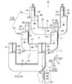
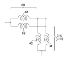
- FIG. 8 shows an equivalent circuit of the first annular coil body 41 and the second annular coil body 42 of one unit 31 shown in FIG. 4, and the first plate portion 61 and the second plate portion 62 of one bridge portion 60. An example is shown.
- FIG. 9 shows an example of the flow of the drive current Id in the first unit 31A and the second unit 31B shown in FIG.
- the first unit 31 ⁇ / b> A located on the front side and the second unit 31 ⁇ / b> B located on the rear side are separated from each other in order to facilitate the drawing of the flow of the drive current Id.
- the middle part of the bridge portion 60 that electrically connects the first unit 31A located on the front side and the second unit 31B located on the rear side is shown by being divided. Yes.
- the drive current Id shown in FIG. 9 is divided into a current Ir1 passing through the first plate-like portion 61A of the bridge portion 60 and a current Ir2 passing through the second plate-like portion 62A of the bridge portion 60.
- the current Ir1 that has passed through the first plate-like portion 61A of the bridge portion 60 located on the front side is the first connection piece 64 of the bridge portion 60, the first other side terminal portion 45 of the first unit 31A, and the second other side.
- the U-shaped first coil base 43 and the second coil base 47 of the first unit 31 ⁇ / b> A are passed through the terminal portion 49.
- the current Ir1 is passed through the first one-side terminal portion 44, the second other-side terminal portion 48, and the first connection piece 63 of the first unit 31A, and the first plate-like shape of the bridge portion 60 on the next rear side. It passes through the part 61A and the second plate-like part 62A and reaches the first other terminal part 45 and the second other terminal part 49 of the first unit 31A of the first unit 31B.
- the current Ir2 that has passed through the second plate-like portion 62A of the front bridge portion 60 is the second connection piece 66 of the bridge portion 60, the first other side terminal portion 45 of the first unit 31A, and the second.
- the U-shaped first coil base 43 and the second coil base 47 of the first unit 31 ⁇ / b> A are passed through the other side terminal portion 49.
- the current Ir2 passes through the first one-side terminal portion 44, the second other-side terminal portion 48, and the second connection piece 65 of the first unit 31A, and the first plate-like shape of the bridge portion 60 on the next rear side.
- the drive current Id flows through each of the first unit 31A and the second unit 31B.
- the illustrated example of the flow of the drive current Id shown in FIG. 9 is an example for easy understanding and is not particularly limited.
- the first annular coil body 41 and the second annular coil body 42 are overlapped and bonded using a bonding material, whereby a plurality of pairs of first units 31 ⁇ / b> A and first 2 unit 31B is made.
- a plurality of bridge portions 60 are made by bonding the first plate member 61 and the second plate member 62 together using a bonding material.
- 10 sets of units 31 are inserted along the radial direction RD so that the space factor of the coil in the slot 21 of the stator core 20 can be increased as much as possible. Then, it will be in a state of being closely stacked.
- a bridge portion 60 is inserted between the adjacent first unit 31A and second unit 31B.
- the bridge portion 60 is disposed so as to close the openings 34 and 33 of the two adjacent units 31A and 31B.
- the bridge portion 60 includes a first one-side terminal portion 44 and a second one-side terminal of a set on one side of the first annular coil body 41 and the second annular coil body 42 of the first unit 31A located on the front side in FIG. Part 48, the first other terminal part 45 and the second terminal part 45 of the other set of the first annular coil main body 41 and the second annular coil main body 42 of the second unit 31B arranged in the rear side in FIG.
- the other terminal portion 49 is electrically connected and fixed.
- each stator coil 30 performs a predetermined three-phase connection.
- the bridge unit 60 When the bridge unit 60 is arranged in this way and the adjacent first unit 31A and the second unit 31B are electrically connected, conductive adhesive, cream solder, solder plating, copper brazing plating, etc. A conductive bonding material is used. Thereby, the first unit 31A, the second unit 31B, and the bridge portion 60 can be electrically connected simultaneously with the mechanical joining.
- first unit 31A, the second unit 31B, and the bridge portion 60 are joined by applying a conductive adhesive or cream solder
- the first unit 31A, the second unit 31B, and the bridge portion 60 are joined. It is desirable to provide a plurality of minute depressions on the coating surface. As a result, these minute depressions can be left behind when a conductive adhesive or cream solder is applied, thereby further ensuring the bonding ability.
- solder erosion phenomenon can be prevented by forming another layer such as a nickel layer under the solder plating layer by plating.
- the conductive adhesive can be adopted as long as it is a product specification that uses a motor at a use temperature of 100 ° C. or less, for example. Solder plating can be used in product specifications that use a motor at a working temperature of 200 ° C. or lower.
- a conductive adhesive preferably made of a material containing metal nanoparticles is used as a bonding material for electrically connecting the first annular coil body 41 or the second annular coil body 42 and the bridge portion 60. Can be adopted. For example, in the case of a product specification that uses a motor at a use temperature exceeding 200 ° C., brazing or a bonding material containing metal nanoparticles can be used as the conductive adhesive.
- FIG. 10 shows a second embodiment of the present invention.
- the first embodiment shown in FIG. 7 described above simplifies the formation of the conductive bonding material and the method of applying the insulating coating, and the productivity of the first unit 31A, the second unit 31B, and the bridge portion 60 is simplified. This is an example that emphasizes.
- the second embodiment shown in FIG. 10 is an example in which the performances of the first unit 31A, the second unit 31B, and the bridge unit 60 as drive coils are emphasized.
- the opposing surfaces of the first annular coil body 41 and the second annular coil body 42 of the first unit 31A and the second unit 31B, and the first plate member 61 and the second plate of the bridge portion 60 are coated with a conductive bonding material that is a conductive surface CD.
- portions other than the portion where the bonding material is applied are provided with insulating coating as the insulating surface IR.
- the entire surface of the first coil base portion 43, the first one-side terminal portion 44, and the first other-side terminal portion 45 of the first annular coil body 41 shown in FIG. 10 is a conductive surface CD.
- the surface of the second coil base portion 47 of the second annular coil body 42 is an insulating surface IR, but the surfaces of the second one-side terminal portion 48 and the second other-side terminal portion 49 of the second annular coil body 42 are The conductive surface CD.
- the entire back surface of the first coil base portion 43, the first one-side terminal portion 44, and the first other-side terminal portion 45 of the first annular coil body 41 is an insulating surface IR.
- the back surface of the second coil base portion 47 of the second annular coil body 42 is the conductive surface CD, but the back surfaces of the second one-side terminal portion 48 and the second other-side terminal portion 49 of the second annular coil body 42 are The insulating surface IR.
- the conductive surface CD on the surface of the first coil base 43 of the first annular coil body 41 and the conductive surface CD on the back surface of the second coil base 47 of the second annular coil body 42 are closely overlapped as an opposing surface. Is done.
- the entire surface of the first plate portion 61A and the first connection pieces 63 and 64 of the first plate member 61 shown in FIG. 10 is an insulating surface IR.
- the surface of the second plate-like portion 62A of the second plate member 62 is the insulating surface IR, but the surfaces of the second connection pieces 65 and 66 are the conductive surface CD.
- the entire back surface of the first plate-like portion 61A of the first plate member 61 and the left and right first connection pieces 63, 64 is a conductive surface CD.
- the back surface of the second plate-like portion 62A is a conductive surface CD, and the back surfaces of the left and right second connection pieces 65 and 66 are insulating surfaces IR.
- FIG. 11 shows a third embodiment of the present invention.
- the third embodiment shown in FIG. 11 is a modification of the structural example of the motor 1 in the first embodiment shown in FIG.
- the components in the motor 1 shown in FIG. 11 that are substantially the same as those in the motor 1 shown in FIG.
- the first annular coil main body 41 and the second annular coil main body 42 of each stator coil 30 are formed in a straight line, and thus have a rectangular cross section.
- the first annular coil body 41 and the second annular coil body 42 that respectively constitute the first unit and the second unit of each stator coil 30.
- the section is curved in an arc shape in accordance with the curvature of the ring-shaped stator core 20 along the circumferential direction TA.
- annular coil main body 42 are formed in an arc-shaped cross section along the circumferential direction TA, each 1st cyclic
- the bridge portion is also formed in an arc shape in accordance with the arc. Accordingly, the stator coil 30 shown in FIG. 11 can be fitted and fitted more closely in accordance with the shape of each slot 21, so that the space factor of the coil can be increased.
- FIG. 12 shows a fourth embodiment of the present invention.
- each of the first annular coil body 41 and the second annular coil body 42 of each of the first unit and the second unit is similar to the third embodiment described above.
- the arc-shaped cross section is curved.
- the thicknesses H1, H2, and H3 of the RD are gradually reduced due to the magnitude relationship of H1> H2> H3.
- the magnitude of the electrical resistance value of the stator coil depends on the unit having the smallest cross-sectional area among all the units. Determined. Therefore, it is desirable to make the cross-sectional area of each unit uniform and make the electric resistance value in each unit uniform.
- each of the first annular coil main body 41 and the second annular coil main body 42 located on the outer side can be made constant with respect to the radial direction RD.
- the electrical resistance value of the stator coil 30 as a drive coil can be made uniform in each unit.
- a unit having an unnecessarily large cross-sectional area can be eliminated as compared with a unit having the smallest cross-sectional area, so that the slot area can be used more effectively.
- the insulating coating as the insulating material for insulating the insulating material between the first annular coil main body 41 or the second annular coil main body 42 and the first plate member and the second plate member of the bridge portion 60, High heat-resistant coating materials are preferable. This considers the case where the environment when the motor 1 is used is high temperature.
- the heat resistant temperature of a general high heat resistant enameled wire is about 220 ° C., and the heat resistance of the enameled wire is a bottleneck of the heat resistant temperature of the motor.
- a polyimide coating is used to increase the heat resistant temperature, the heat resistant temperature can be increased up to 280 ° C.
- polyimide since polyimide is expensive, the production amount is very small.
- the coil 30 of the motor 1 does not have a structure in which a linear object is wound, and therefore it is not necessary to bend the coil itself at the time of winding. It can be used as an insulating coating.
- a mica sheet, ceramic coating, or glass coating can be employed as the inorganic insulating material.
- the mica sheet has a heat resistance of 750 ° C.
- the ceramic coating has a heat resistance of 800 ° C. or more
- the glass coating has a heat resistance of 1000 ° C.
- the heat-resistant temperature that has been in the range of 200 ° C. in the conventional motor coil can be increased all at once, and in the embodiment of the present invention, the heat-resistant temperature can be raised to 700 ° C. or higher.
- the insulating coating material can be changed from an organic material such as plastic to an inorganic material such as a seto or seto glaze, the heat resistance of the motor including the coil can be dramatically increased.
- the insulating material such as Seto is broken when the wire rod is bent, so that it cannot be applied.
- an inorganic insulating material can be applied to the coil 30 as an insulating coating.
- the metal plate (for example, copper or aluminum) of the raw material for producing the 1st annular coil main body 41, the 2nd annular coil main body 42, the 1st plate member 61, and the 2nd plate member 62 is in the state of a metal plate. It is considered that the method of performing the press working after the insulating coating is the most productive. For this purpose, it is desirable to perform an insulating process that does not crack and peel even when press working. In this case, it is desirable to apply an inorganic insulating coating having a thickness of several ⁇ m, which is used for insulating a magnetic steel sheet, to the material. (Fifth embodiment)
- FIG. 13 shows a fifth embodiment of the present invention. In the first embodiment shown in FIG.
- the bridge portion 60 is configured by overlapping a first plate member 61 and a second plate member 62 in the radial direction RD.
- the bridge portion 60 of the stator coil 30 is constituted by a single plate member 60M. That is, the bridge portion may be composed of a plurality of members or a single member. Thereby, the number of parts for constituting stator coil 30 can be reduced.
- the coil 30 of the embodiment which is an example of the coil of the present invention is a coil used for the motor 1 that rotates about the central axis 4 extending in the vertical direction.
- the coil 30 includes a plurality of first units 31A and second units 31B that are arranged adjacent to each other in the radial direction RD, and a bridge unit 60 that is electrically connected to the first units 31A and the second units 31B.
- the first unit 31A and the second unit 31B have a first annular coil body 41 made of a metal plate, and a second annular coil body 42 made of a metal plate overlapping the first annular coil body 41 in the radial direction RD.
- the first annular coil body 41 has an opening 33 with an annular part opened above the axial direction CL of the central shaft 4.
- the first annular coil body 41 has a first coil base 43, a first one-side terminal portion 44, and a first other-side terminal portion 45.
- the second annular coil body 42 has an opening 34 with an annular part opened upward.
- the second annular coil main body 42 includes a second coil base 47, a second one-side terminal portion 48, and a second other-side terminal portion 49.
- the bridge portion 60 is a substantially plate-shaped metal member that covers the opening 33 of the first coil base 43 and the opening 34 of the second coil base 47.
- One side in the circumferential direction TA of the bridge portion 60 is connected to the first one-side terminal portion 44 and the second one-side terminal portion 48 in the first unit 31A.
- the other side in the circumferential direction TA of the bridge portion 60 is connected to the first other side terminal portion 45 and the second other side terminal portion 49 in the second unit 31B adjacent in the radial direction RD.
- the first annular coil main body 41 and the second annular coil main body 42 of the first unit 31A and the second unit 31B do not need to be changed in thickness throughout.
- the first annular coil body 41 and the second annular coil body 42 do not need to be formed by processing a part thereof thinly.
- the first annular coil body 41 and the second annular coil body 42 of the first unit 31A and the second unit 31B can be easily manufactured at the manufacturing site.
- a plurality of first units 31A and second units 31B arranged in the radial direction RD and a plurality of bridge portions 60 electrically connected to these units are combined.
- the slots 21 can be closely stacked without creating a gap. Therefore, assembly can be easily performed while increasing the space factor of the coil when the coil is disposed in the slot.
- the second annular coil body 42 is located outside the first annular coil body 41 in the radial direction RD.
- the bottom surface 51 of the second one-side terminal portion 48 and the bottom surface 51 of the second other-side terminal portion 49 are in contact with the upper surface 46 of the first one-side opening end portion 41R and the upper surface 46 of the first other-side opening end portion 41T.
- the second annular coil body 42 is in contact with the first annular coil body 41 in the axial direction CL, thereby positioning the second annular coil body 42 and the first annular coil body 41 in the axial direction CL. can do. For this reason, the second annular coil body 42 and the first annular coil body 41 can be easily assembled so as to overlap without being displaced.
- the bridge part 60 is composed of a first plate member 61 and a second plate member 62.
- the first plate member 61 includes a first plate portion 61A extending in the circumferential direction TA, and first terminal portions 44 and 45 and second terminal portions 48 and 49 from both ends of the first plate portion 61A on the circumferential direction TA.
- First connection pieces 63 and 64 extending in the circumferential direction TA.
- the second plate member 62 includes a second plate-like portion 62A extending in the circumferential direction TA, and both ends in the circumferential direction TA of the first plate-like portion 61A from the ends on both sides of the second plate-like portion 62A in the circumferential direction TA.
- the first plate-like portion 61A is located on the outer side in the radial direction RD (RD1) than the second plate-like portion 62A.
- the first connection piece 63 and the second connection piece 65 on one side are located on the outer side (RD1) in the radial direction RD than the first connection piece 64 and the second connection piece 66 on the other side.
- the first plate-like portion 61A and the second plate-like portion 62A overlap in the radial direction RD, and the first connection pieces 63 and 64 and the second connection pieces 65 and 66 overlap in the axial direction CL.
- the bridge portion 60 includes the first annular coil body 41 and the second annular coil body 42 of the first unit 31A, and the first annular coil body 41 and the second annular coil body of the second unit 32A. 42 can be electrically connected.
- the first connecting piece 63 on the one side in the circumferential direction TA and the surface on the inner side (RD2) in the radial direction RD of the second connecting piece 65 are the first one side terminal portion 44 located on the one side in the circumferential direction TA in the first unit 31A.
- the second one-side terminal portion 48 is connected to the surface on the outer side (RD1) in the radial direction RD.
- the inner surfaces of the first connection piece 64 and the second connection piece 66 on the other side in the circumferential direction TA on the other side in the radial direction RD are the first other side terminal portion 45 located on the other side in the circumferential direction TA of the second unit 31B and The second other side terminal portion 49 is connected to the surface on the outer side (RD1) in the radial direction RD.
- the bridge unit 60 can electrically connect the first unit 31A and the second unit 31B.
- a conductive bonding material is applied to the opposing surfaces of the first annular coil body 41 and the second annular coil body 42 and the opposing surfaces of the first plate-like portion 61A and the second plate-like portion 62A of the bridge portion 60.
- the opposing surface of the 1st annular coil main body 41 and the 2nd annular coil main body 42 and the opposing surface of the 1st plate-shaped part 61A and the 2nd plate-shaped part 62A of the bridge part 60 are via a joining material. Can be electrically connected while fixed.
- portions other than the portion where the bonding material is applied are coated with insulation. According to the said structure, insulation can be ensured by insulation-coating a part other than a bonding material.
- Either one of the opposing surfaces of the first annular coil body 41 and the second annular coil body 42 and the opposing surfaces of the first plate-like portion 61A and the second plate-like portion 62A of the bridge portion 60 is coated with insulation. Yes.
- the insulating surfaces are provided between the opposing surfaces of the first annular coil body 41 and the second annular coil body 42 and the opposing surfaces of the first plate-like portion 61A and the second plate-like portion 62A of the bridge portion 60. It can be secured.
- the first connection pieces 63 and 64 of the first plate member 61 of the bridge portion 60 and the second connection pieces 65 and 66 of the second plate member 62 are formed with the thickness of the first annular coil body 41 and the second value.
- the total thickness of the annular coil body 42 falls within the range of the thickness.
- the first connection pieces 63 and 64 and the second connection pieces 65 and 66 of the second plate member 62 do not protrude in the radial direction RD.
- the width in the circumferential direction TA of the first one-side terminal portion 44 and the first other-side terminal portion 45 and the width in the circumferential direction TA of the second one-side terminal portion 48 and the second other-side terminal portion 49 are the first annular coil. It is half the width of the main body 41 and the second annular coil main body 42 in the circumferential direction TA. According to the above configuration, the first one-side terminal portion 44, the first other-side terminal portion 45, the second one-side terminal portion 48, and the second other-side terminal portion 49 are arranged side by side without interfering with each other. Can be placed.
- the first annular coil body 41 or the second annular coil body 42 is U-shaped. According to the said structure, since the 1st annular coil main body 41 and the 2nd annular coil main body 42 can be made using the same metal mold
- the insulating material between the first annular coil body 41 or the second annular coil body 42 and the insulating material for insulating between the first plate-like portion 61A and the second plate-like portion 62A of the bridge portion is a high heat-resistant coating.
- the joining material that electrically joins the first annular coil body 4 or the second annular coil body 42 and the bridge portion 60 is a material containing metal nanoparticles. According to the above configuration, the coil can be used even when the operating temperature is high.
- the first annular coil body 41 or the second annular coil body 42 has the same shape in a front view, and the first plate-like portion and the second plate-like portion of the bridge portion have the same shape in a front view. According to the above configuration, the first annular coil main body 41 and the second annular coil main body 42 can be made using the same mold, so that the manufacture is easy and the manufacturing cost can be reduced. it can.
- the coil 30 is inserted into the plurality of slots 21 of the stator 20.
- the stator can be obtained by easily assembling the coil while increasing the space factor of the coil 30 in the slot 21.
- the motor 1 includes a stator having a stator coil, and a rotor having a magnet and rotating by energizing the stator coil. According to the above configuration, a motor with an increased space factor of the coil 30 in the slot 21 can be obtained, and a high-performance motor that is easy to manufacture and has a high torque density can be obtained.
- the present invention is not limited to the above embodiment, and various modifications can be made without departing from the scope of the claims.
- Each structure of the said embodiment of this invention can abbreviate
- a part of the annular shape is opened only above the axial direction CL.
- the present invention is not limited to this, and the first annular coil body and the second annular coil body are annular. May be opened in the circumferential direction TA.
- the coil of the motor according to the embodiment of the present invention is used for a motor that rotates about a central axis 4 that extends in the vertical direction.
- the coil of the present invention is not limited to the case where it is provided in the stator (stator).
- the coil can be used not only for the stator but also for the rotor (rotor).
- the core on which the coil is disposed is the rotor.
- the motor 1 described above uses a three-phase alternating current as a drive current.
- the motor of the present invention may have a structure using a single-phase current or a two-phase drive current.
- the rotor 2 of the motor 1 is an outer rotor type motor that rotates with the central shaft 4 around the stator 3.
- the present invention is not limited to this, and the motor of the present invention may be a so-called inner rotor type motor in which the stator is around and the rotor rotates inside the stator.
Landscapes
- Engineering & Computer Science (AREA)
- Power Engineering (AREA)
- Windings For Motors And Generators (AREA)
Abstract
【課題】 コイルの占積率を上げながら、容易に組み立てをすることができるコイル、ステータおよびモータを提供する。 【解決手段】 コイル30は、径方向RDに隣り合う複数配置される第1のユニット31Aおよび第2のユニット31Bと、第1のユニット31Aおよび第2のユニット31Bに電気的に接続される複数のブリッジ部60を備え、第1のユニット31Aおよび第2のユニット31Bは、金属板の第1環状コイル本体41と、第1環状コイル本体41と径方向RDに重なる金属板の第2環状コイル本体42を有し、ブリッジ部60の周方向TA一方側は、第1のユニット31Aにおける第1一方側端子部44および第2一方側端子部48と接続し、ブリッジ部60の周方向TA他方側は、径方向RDに隣り合う第2のユニット31Bにおける第1他方側端子部45および第2他方側端子部49と接続する。
Description
本発明は、コイル、ステータおよびモータに関する。
近年、様々な製品の小型化や薄型化が求められるようになっている。製品の小型化等に伴い、その製品に搭載されるモータについても、小型化や薄型化が求められている。一般に、モータの出力はモータの体積に比例する。そのため、モータが小型化すると、出力までも低下してしまう。しかし、製品が小型化したとしても、モータは、当然のことながら、従来以上のトルクを発生させることが求められている。モータの従来以上にトルクを上げるためにはトルク密度を向上させる必要がある。また、製品の小型化に伴ってモータの軽量化が求められている。
このモータのトルク密度を向上させるには、一般には、ステータのスロットにおけるコイルの「占積率」を高めることが挙げられる。この占積率とは、ステータのスロットの断面積とそのスロット内に配置されているコイル断面積との割合である。このコイルの占積率を上げるためには、コイルを形成する線材のターン数を増加させることが考えられる。しかし、丸線または平角線の線材を用いる場合、巻線機のノズルの大きさや巻線スペース等の問題から、スロット内において巻き付け可能なターン数には上限があり、ある一定以上の占積率を実現することが難しかった。
特許文献1には、モータのトルク密度を向上させるために、モータの占積率(線積率)を向上させるモータのコイル構造が提案されている。このモータのコイル構造では、ステータ鉄心のスロット内に、スロット内コイルが積層して組み込まれている。スロット内コイルの一端部の端面と他端部の端面には、それぞれスロット間渡りコイルが個別に接合されている。スロット内コイルが直線状の部材であり、スロット間渡りコイルはバー状の部材である。スロット内コイルの一端部と他端部は、このスロット間渡りコイルをはめ込むために、スロット内コイルの厚みに比べて、薄肉状に形成されている。
ところが、特許文献1に記載のモータのコイル構造にみられるようにスロット内コイルを製造する際に、スロット内コイルの厚みの一端部と他端部を区別して薄肉状に作製することは、実際の製造現場ではきわめて困難である。そこで、本発明は、コイルの占積率を上げながら、容易に組み立てをすることができるコイル、ステータおよびモータを提供することを目的とする。
本発明のコイルは、上下方向に延びる中心軸を中心に回転するモータに用いられるコイルであって、中心軸を中心とする径方向に隣り合う複数配置される第1のユニットおよび第2のユニットと、ユニットに電気的に接続されるブリッジ部と、を備え、ユニットは、金属板の第1環状コイル本体と、第1環状コイル本体と径方向に重なる金属板の第2環状コイル本体を有し、第1環状コイル本体は、環状の一部が中心軸の軸方向上方に開口され、開口端のうち中心軸を中心とする周方向一方側の第1一方側開口端部と、周方向他方側の第1他方側開口端部と、を有する第1コイル基部と、第1一方側開口端部の周方向一方側から、一体に軸方向に延びる第1一方側端子部と、第1他方側開口端部の周方向一方側から、一体に軸方向に延びる第1他方側端子部と、を有し、第2環状コイル本体は、環状の一部が軸方向上方に開口され、開口端のうち周方向一方側の第2一方側開口端部と、周方向他方側の第2他方側開口端部と、を有する第2コイル基部と、第2一方側開口端部の周方向他方側から、一体に第1一方側開口端部に沿って、軸方向に延びる第2一方側端子部と、第2他方側開口端部の周方向他方側から、一体に第1他方側開口端部に沿って、軸方向に延びる第2他方側端子部と、を有し、ブリッジ部は、第1コイル基部の開口部と第2コイル基部の開口部を覆う略板形状の金属部材であり、ブリッジ部の周方向一方側は、第1のユニットにおける第1一方側端子部および第2一方側端子部と接続し、ブリッジ部の周方向他方側は、径方向に隣り合う第2のユニットにおける第1他方側端子部および第2他方側端子部と接続することを特徴とする。
また、本発明のステータは、コイルが、複数個のスロットに差し込まれていることを特徴とする。さらに、本発明のモータは、ステータコイルを有するステータと、マグネットを有しステータコイルに通電することで回転するロータと、を備えることを特徴とする。
本発明は、コイルの占積率を上げながら、容易に組み立てをすることができるコイル、ステータおよびモータを提供することができる。
以下に、本発明の好ましい実施形態を、図面を参照して詳しく説明する。尚、以下に述べる実施の形態は、本発明の好適な具体例であるから、技術的に好ましい種々の限定が付されているが、本発明の範囲は、以下の説明において特に本発明を限定する旨の記載がない限り、これらの態様に限られるものではない。
(第1実施形態)
<モータ1の全体構造>
図1は、本発明のモータの第1実施形態を示す軸方向CLに沿った縦断面図である。図1に示すモータ1は、例えば自動車、電動自動車、電動アシスト機器、電動飛行機、マルチコプター等の移動体、ロボット等の産業機器、情報記録媒体を回転する情報記録再生機器、家電製品、事務機器、医療機器等の各分野の搭載対象物に搭載できる。
<モータ1の全体構造>
図1は、本発明のモータの第1実施形態を示す軸方向CLに沿った縦断面図である。図1に示すモータ1は、例えば自動車、電動自動車、電動アシスト機器、電動飛行機、マルチコプター等の移動体、ロボット等の産業機器、情報記録媒体を回転する情報記録再生機器、家電製品、事務機器、医療機器等の各分野の搭載対象物に搭載できる。
図1に示すように、モータ1は、ステータ2と、ロータ3を備えている。ステータ2は固定子であり、ロータ3は回転子である。このモータ1のロータ3は、例えばステータ2の周囲において周方向TAに沿って中心軸4とともに回転する、いわゆるアウターロータ型のモータである。ステータ2は、例えば駆動対象物の固定部位に固定される。ロータ3は、ステータ2に対して、中心軸4の軸方向CLを中心にして、回転可能に支持されている。
ここで、本発明の実施形態では、モータ1は中心軸4が決まっている。このため、図1に例示するように、中心軸4に平行な方向を一点鎖線で示すように、「軸方向」CLとして記載する。また、ロータ3は、扁平で略円筒形状であるので、軸方向CLに直交する方向を矢印で示すように、「径方向」RDとして記載する。そして、軸方向CLの円弧に沿う方向を矢印で示すように、「周方向」TAとして記載する。図1では、中心軸4の軸方向CLは、図面において上下方向である。占積率とは、モータ1において、ステータ2のスロットの断面積に対して、そのスロット内に配置されているコイルの断面積の総計の割合である。また、モータ1の中心軸方向における上方を単に「上方」と呼び、下方を単に「下方」と呼ぶ。図面における紙面側を「表面」と呼び、紙面の裏側を「裏面」と呼ぶ。また、図面における「前側」は、径方向外側に対応し、「後側」は径方向内側に対応する。なお、上下方向・表裏・前後は、実際の機器に組み込まれたときの位置関係や方向を示すものではない。このモータ1は、ステータ2のスロットの面積に対するコイル(ステータコイル)の断面積を上げる。占積率を上げるということは、スロットの断面積に対して、コイルの占める面積が大きくなることである。コイルのターン数が一定であって、コイルの外径を大きくした場合には、電気抵抗値を下げることができる。コイルの電気抵抗値を下げることにより大きな電流を流すことができるようになり、モータ1は、小型で軽量であって、トルク密度を上げて高出力(高トルク)を得ることができるようになっている。
図1と図2を参照して、モータ1のステータ2とロータ3のそれぞれの構造例を説明する。図2は、図1に示すモータの構造を示す平面図である。ただし、図2では、図面の簡単化のために、図1に示す中心軸4と円筒状の保持部6の図示を省略している。まず、ステータ2の構造例を説明する。図1に示すように、ステータ2は、固定板部5と、円筒状の保持部6と、ステータユニット10と、第1軸受11と、第2軸受12等を有している。固定板部5は、例えばモータ1を制御するための電子部品等が搭載されている電子基板等であるが、特に限定されない。
図1に示す円筒状の保持部6は、大径部分6Aと小径部分6Bを有している。大径部分6Aは上端開口部6Mを有し、小径部分6Bは下端開口部6Nを有している。大径部分6Aは、その内部に第1軸受11を保持している。小径部分6Bは、その内部には、第2軸受12を保持している。第1軸受11と第2軸受12は、例えばボールベアリングである。第1軸受11は、中心軸4の上側の位置の軸受部であり、第2軸受12は、下側の位置の軸受部である。第1軸受11は、第2軸受12に比べて大型のサイズのものが採用されている。
図1に示す第1軸受11の外輪11Aが、この大径部分6Aの内周面に固定され、第2軸受12の外輪12Aが、小径部分6Bの内周面に固定されている。第1軸受11の内輪11Bが、この中心軸4の小径部分4Bの外周面に固定され、第2軸受12の内輪12Bが、中心軸4の小径部分4Bの外周面に固定されている。小径部分6B内には、第2軸受12の位置を固定するための留め具6Cが配置されている。
図1に示す第1軸受11の外輪11Aと内輪11Bの間には、軸受を構成するための複数の玉11Cが間隔をおいて配置されている。第2軸受12の外輪12Aと内輪12Bの間には、複数の玉12Cが間隔をおいて配置されている。これにより、中心軸4は、第1軸受11と第2軸受12により、軸方向CLを中心にして、回転可能に支持されている。ただし、第1軸受11と第2軸受12は、例えばボールベアリングであるが、これに限らず、モータの用途や仕様に応じて、滑り軸受や、流体軸受などの他の形式の軸受を用いても良い。図1に示すステータユニット10の構造例は、後で詳しく説明するが、このステータユニット10は、保持部6の小径部分6Bの外周面6Dに固定されている。ステータユニット10は、図1に示す固定板部5から供給される駆動電流に応じて、磁束を発生させる電機子である。
次に、ロータ3の構造例を説明する。図1に示すロータ3は、中心軸4と、ハウジング部13と、複数の駆動用のマグネット14を有する。この中心軸4は、大径部分4Aと小径部分4Bを有している。大径部分4Aは、例えば回転しようとする対象物に対して装着される部分である。小径部分4Bの外周面には、上述したように、第1軸受11の内輪11Bと第2軸受12の内輪12Bが固定されている。ハウジング部13は、ステータユニット10の周囲を覆っている。ハウジング部13は、周壁部分13Aと、底部13Bと、取付け凹部13Cを有する円形状の部材である。中心軸4の小径部分4Bの端部4Cが、ハウジング部13の取付け凹部13Cの穴13Dに、例えば圧入により固定されている。
図1に示すように、ハウジング部13の周壁部分13Aは、ステータユニット10の外周に対して径方向RDに対向している。図1と図2に示すように、周壁部分13Aの内周面には、複数個のマグネット14が等間隔に周方向TAに配列されている。例えば、マグネット14は14個であり、接着剤を用いて配列されている。これらのマグネット14のN極の磁極面と、S極の磁極面とが、周方向TAに交互に並んでいる。なお、複数のマグネット14を用いるのに代えて、N極とS極が周方向に交互に着磁されている1つの円環型のマグネットを、ハウジング部13の周壁部分13Aに貼り付けても良い。このマグネット14のN極とS極の配置数は、特に限定されず、任意に選択できる。これにより、ステータユニット10の駆動用のコイルに対して、図示しない駆動電流供給部から駆動電流を供給して磁束を発生させると、複数のマグネット14との間の磁束の作用により、中心軸4を中心にして周方向TAにトルクを発生する。このため、ロータ3は、ステータ2に対して、軸方向CLを中心にして回転するようになっている。
<ステータ2の構造例>
次に、ステータ2のステータユニット10の構造例を、図1と図2を参照しながら、詳しく説明する。図1と図2に示すように、ステータユニット10は、保持部6の小径部分6Bの外周面6Dに固定されている。ステータユニット10は、ハウジング部13と複数のマグネット14の径方向内側に位置する。ステータユニット10は、マグネット14に対して、径方向に所定の隙間を離して配置されている。このステータユニット10は、リング状のステータコア20と、複数のステータコイル30を有している。本実施形態では、コイル30は、ロータ3側ではなく、ステータ2側に配置されるので、ステータコイルと呼ぶ。
次に、ステータ2のステータユニット10の構造例を、図1と図2を参照しながら、詳しく説明する。図1と図2に示すように、ステータユニット10は、保持部6の小径部分6Bの外周面6Dに固定されている。ステータユニット10は、ハウジング部13と複数のマグネット14の径方向内側に位置する。ステータユニット10は、マグネット14に対して、径方向に所定の隙間を離して配置されている。このステータユニット10は、リング状のステータコア20と、複数のステータコイル30を有している。本実施形態では、コイル30は、ロータ3側ではなく、ステータ2側に配置されるので、ステータコイルと呼ぶ。
図2に示すように、ステータコア20の外周面20Aは、ハウジング部13に配置された複数のマグネット14に対して、径方向に隙間を離して配置されている。図1に示すように、ステータコア20の内周面20Bは、円筒状の保持部6の小径部分6Bの外周面6Dに固定されている。ステータコア20は、例えば複数枚の鋼板を軸方向CLに沿って積層した積層鋼板である。
図2に示すように、ステータ2は、複数のスロット21を有している。ステータコア20は、ステータコア20から径方向に突出する複数のティースを有する。複数のティースには、コイルが巻回される。複数のスロット21は、図2の紙面において軸方向CLに平行な方向に形成されている、例えば略断面台形状の間隙である。すなわち、各スロット21は、ティースとティースとの間の間隙である。各スロット21は、軸方向CLを中心にして、所定角度毎、例えば角度30度毎に、12個形成されている。このスロット21の形成個数と断面形状は、図2に示す例には限定されず、任意に選択できる。
図2に示すように、複数組のステータコイル30が、複数のスロット21に対して装着されている。各組のステータコイル30は、隣接する2つのスロット21,21に跨って挿入して、ステータコア20のティースに対して固定されている。図2に示す例では、12組のステータコイル30が、12個のスロット21に対して、装着されている。ステータコイル30は、樹脂等の電気絶縁材の間を介して、隣接する2つのスロット21に跨って挿入されている。
図3は、図2に示す隣接する2つのスロット21と、1組のステータコイル30の領域RRを、代表して示している。なお、図3では、理解の便宜のため、1組のステータコイル30の中間部分の図示を省略している。 図2と図3に例示するように、各スロット21は、3つの壁部21A,21B,21Cと、2つの突部21Dにより形成されているほぼ台形状の貫通孔である。1つのステータコイル30は、図2と図3に示すように、隣接する2つのスロット21,21にまたがって挿入して固定されている。
<ステータコイル30の構造例> 図3に示すように、1組のステータコイル30は、第1のユニット31Aおよび第2のユニット31Bと、第1のユニット31Aおよび第2のユニット31Bに電気的に接続される複数のブリッジ部60と、を備える。1組のステータコイル30は、複数組の第1のユニット31Aと第2のユニット31Bを、径方向RDに沿って密接するようにして重ねて配置されている。
図2と図3では、例えば10組の第1のユニット31Aと第2のユニット31Bが、モータ1の径方向RDに沿って密接して重ねられている。複数のブリッジ部60は、隣接する第1のユニット31Aと第2のユニット31Bを電気的に接続する電気接続部材である。ブリッジ部60は、スロット21内におけるコイルの占積率をできる限り上げることができるように、通常用いられる線材のコイルの断面積に比べて、断面積の大きい板状の部材である。ステータコイル30の設定数と、ブリッジ部60の設定数は、例えば10組に限定されるものではなく、要求される仕様に応じて設定数を変えることができ、一例として20組であっても良い。このように、複数組の第1のユニット31Aと第2のユニット31Bと複数のブリッジ部60が電気的に接続されている構造である。第1のユニット31Aと第2のユニット31Bは、径方向RDに沿って密着して重ねた状態で、スロット21,21内に挿入できる。このため、ステータコイル30の構造は、通常の巻線をスロットを通してティースに巻くのに比べて、スロット21内におけるコイルの占積率をできる限り上げることができる。
次に、図3と図4と図5を参照して、第1のユニット31Aと第2のユニット31Bの構造例を説明し、その後に図3と図4と図6を参照して、各組のブリッジ部60の構造例を説明する。図4は、図3に示す隣接して重ねられる第1のユニット31Aと第2のユニット31Bと、第1のユニット31Aと第2のユニット31Bの間を電気的に接続するための1組のブリッジ部60の構造例を示す斜視図である。図5は、第1のユニット31Aと第2のユニット31Bの構造例を示す斜視図である。図6は、1組のブリッジ部60の構造例を示す斜視図である。図4、図5に示すように、径方向RDの外側方向は、矢印RD1で示し、径方向RDの内側方向は、矢印RD2で示している。軸方向CLと周方向TAと径方向RDは、互いに直交している。
まず、図3と図4と図5を参照して、第1のユニット31Aと第2のユニット31Bの構造例を説明するが、第1のユニット31Aと第2のユニット31Bの構造は、同じである。これにより、第1のユニット31Aと第2のユニット31Bの構造を同じものにすることで、ステータコイルの製造が容易になり、コストの低減が図れる。図4では、第1のユニット31Aと第2のユニット31Bを示しており、各ユニット31A,31Bは、図5に示すような構造を有している。以下では、図5と図4を参照して、第1のユニット31Aの構造を代表して説明するが、第2のユニット31Bの構造も同じである。
図5と図4に例示するように、第1のユニット31Aは、金属板の第1環状コイル本体41と、この第1環状コイル本体41と径方向RDに重なる金属板の第2環状コイル本体42を有している。図5に示す第1環状コイル本体41または第2環状コイル本体42は、正面視にてほぼ同一形状である。これにより、第1環状コイル本体41または第2環状コイル本体42は、例えばほぼ同一形状の金型を用いてプレス加工することができるので、製造が容易であり、製造コストの低減が図れる。
図5に示すように、第1環状コイル本体41は、環状の一部が軸方向CLの上方に開口されることで開口部33を有する。第1環状コイル本体41は、第1コイル基部43を有する。この第1コイル基部43は、周方向TAの一方側の第1一方側開口端部41Rと、周方向TAの他方側の第1他方側開口端部41Tと、を有する。しかも、第1環状コイル本体41は、第1一方側開口端部41Rの周方向TAの一方側から、軸方向CLに向けて延びる第1一方側端子部44と、第1他方側開口端部41Tの周方向TAの一方側から、一体に軸方向CLに延びる第1他方側端子部45を有する。
図5に示すように、第2環状コイル本体42は、環状の一部が軸方向CLの上方に開口されることで開口部34を有している。第2環状コイル本体42は、第2コイル基部47を有する。第2コイル基部47は、この周方向TAの一方側の第2一方側開口端部42Rと、周方向CLの他方側の第2他方側開口端部42Tと、を有する。しかも、第2環状コイル本体42は、第2一方側開口端部42Rの周方向TAの他方側から、第1一方側開口端部41Rに沿って延びた後、軸方向CLに延びる第2一方側端子部48を有する。また、第2環状コイル本体42は、第2他方側開口端部42Tの周方向TAの他方側から、一体に、第1他方側開口端部41Tに沿って延びた後、軸方向CLに延びる第2他方側端子部49を有する。
図5に示すように、第2環状コイル本体42は、第1環状コイル本体41よりも径方向外側(RD1方向)に位置し、重ね合わされる。同じ厚みDを有する第1環状コイル本体41または第2環状コイル本体42を径方向RDに沿って重ね合せると、第1一方側端子部44と第1他方側端子部45と第2一方側端子部48と第2他方側端子部49は、径方向RDに関しては、面一になる構造である。
ここで、第1環状コイル本体41および第2環状コイル本体42は、ほぼ同じ形状を有しており、同じ厚みDを有する導電性に優れた金属板、例えば銅板やアルミニウム板で形成されている。コイル30の占積率を向上するために、金属線材を巻回するコイルと等価の性能を得るためには、導電性の環状板を用いる必要がある。また、第1環状コイル本体41および第2環状コイル本体42は、好ましくは、本実施形態と同等の作用を得ることができる楕円や円形、U字、方形等の形状を適宜採用することができる。この第1環状コイル本体41および第2環状コイル本体42は上記金属板でなる材料を、好ましくは、例えばほぼ同一形状の金型を用いてプレス加工することで作られる。これにより、第1環状コイル本体41または第2環状コイル本体42は、容易かつ短時間で作ることができ製造コストの低減が図れる。
図5に示すように、第1環状コイル本体41および第2環状コイル本体42は、一部が開放された開口部33,34をそれぞれ有し、好ましくは略U字状に形成されている。
第1環状コイル本体41と、第2環状コイル本体42とが、平面視において同一形状であることから、第1環状コイル本体41と第2環状コイル本体42は、同じ金型を用いてU字状に作ることができる。そのため、第1環状コイル本体41と第2環状コイル本体42の製造が容易であり、製造コストが削減できる。図4に示すように、第1環状コイル本体41および第2環状コイル本体42の内側と、ステータコア20との間には、好ましくは絶縁材20Rが配置されている。
第1環状コイル本体41と、第2環状コイル本体42とが、平面視において同一形状であることから、第1環状コイル本体41と第2環状コイル本体42は、同じ金型を用いてU字状に作ることができる。そのため、第1環状コイル本体41と第2環状コイル本体42の製造が容易であり、製造コストが削減できる。図4に示すように、第1環状コイル本体41および第2環状コイル本体42の内側と、ステータコア20との間には、好ましくは絶縁材20Rが配置されている。
まず、図5を参照して、第1環状コイル本体41の形状例を詳しく説明する。図5では、第1環状コイル本体41の開口部33は、軸方向CLについて上に向けた状態である。上述したように、第1環状コイル本体41は、第1コイル基部43と、第1一方側端子部44と、第1他方側端子部45とを有する。第1環状コイル本体41は、ほぼU字型であり、略均一の形成幅W1である。
第1一方側端子部44と第1他方側端子部45は、第1コイル基部43の周方向TAの端部から、軸方向CLの上方に向かって、それぞれ延びている。第1一方側端子部44と第1他方側端子部45の周方向TAの各周方向形成幅W2は、好ましくは第1コイル基部43の周方向形成幅W1の半分になっている。しかも、第1一方側端子部44と第1他方側端子部45は、第1一方側開口端部41Rと第1他方側開口端部41Tのそれぞれ周方向TAの一方側(図5では、紙面において周方向TA左側)に寄った位置に形成されている。第1一方側端子部44と第1他方側端子部45は、図5において、周方向TAの一方側半分において突出して形成されている。この第1一方側端子部44と第1他方側端子部45の周方向TA他方側には、それぞれ位置決め用の当接面である上面46が形成されている。
つづいて、図5を参照して、第2環状コイル本体42の形状例を説明する。第2環状コイル本体42の形状は、第1環状コイル本体41の形状とは一部が異なる。図5では、第2環状コイル本体42の開口部34は、軸方向CLについて上に向けた状態である。上述したように、第2環状コイル本体42は、第2コイル基部47と、第2一方側端子部48と、第2他方側端子部49とを有する。第2環状コイル本体42は、ほぼU字型であり、第2環状コイル本体42の周方向TAと軸方向CLに沿って形成された部分は、同じ形成幅W1を有している。なお、第1一方側端子部44と第1他方側端子部45と、第2一方側端子部48と第2他方側端子部49の軸方向CL方向の突出長さLAは、同じである。
第2一方側端子部48と第2他方側端子部49は、第2コイル基部47の第2一方側開口端部42Rと第2他方側開口端部42Tから、軸方向CLの上方に向かって、それぞれ延びている。第2一方側端子部48と第2他方側端子部49の周方向TAの各形成幅W2は、好ましくは第2コイル基部47の形成幅W1の半分になっている。しかも、第2一方側端子部48と第2他方側端子部49は、それぞれ周方向TAの他方側(図5では、紙面において右側)に寄った位置に形成されている。第2一方側端子部48と第2他方側端子部49は、図5において、他方側半分において突出して形成されている。第2一方側端子部48と第2他方側端子部49の基部には、それぞれ位置決め用の当接面である底面51が形成されている。第2一方側端子部48と第2他方側端子部49の周方向TAの一方側には、上面50が形成されている。
このように、第1一方側端子部44と第1他方側端子部45の右側には、それぞれ上面46が形成されている。しかも、第2一方側端子部48と第2他方側端子部49の基部には、それぞれ底面51が形成されている。ここでいう「底面51」とは、図5で水平面で示されている箇所の裏側の面を指しており、図5の下部に部分拡大断面図に符号51を付して正確な位置を示している。これにより、図5に示すように、第1環状コイル本体41および第2環状コイル本体42が径方向RDについて、密接して重ねた状態にすると、第1環状コイル本体41の第1コイル基部43と第2環状コイル本体42の第2コイル基部47が重なる。しかも、第1一方側端子部44と第1他方側端子部45と第2一方側端子部48と第2他方側端子部49は、それぞれ周方向TAに沿って平行に並んで、径方向RDに関して面一になるように配置されている。そして、図5に示すように、第2一方側端子部48と第2他方側端子部49の底面51,51は、第1一方側開口端部41Rと第1他方側開口端部41Tの上面46,46当接する。
底面51,51の軸方向下面が上面46,46の軸方向上面にそれぞれ当接した状態になると、第2環状コイル本体42が第1環状コイル本体41に対して、軸方向CLに沿った位置決めを行うことができる。これにより、第1環状コイル本体41および第2環状コイル本体42を重ねあわせて組み立てる際に、例えば組立機械を用いて、第1環状コイル本体41および第2環状コイル本体42について、軸方向CL方向と周方向TAについて、互いの位置決めを容易にしかも確実に行うことができる。このため、第1環状コイル本体41および第2環状コイル本体42を位置決めして組み立てる作業性を向上できる。
図5に示すように、第2環状コイル本体42は、折り曲げて形成された底部51を有するので、同じ厚みDを有する第1環状コイル本体41および第2環状コイル本体42を重ねた状態では、第2環状コイル本体42の第2一方側端子部48と第2他方側端子部49の径方向RDの位置は、第1環状コイル本体41の第1一方側端子部44と第1他方側端子部45の径方向RDの位置と、を合わせることができる。つまり、第1一方側端子部44と第1他方側端子部45と、第2一方側端子部48と第2他方側端子部49は、径方向RDについて、面一にすることができる。
これにより、第1一方側端子部44と第1他方側端子部45と、第2一方側端子部48と第2他方側端子部49は、第1環状コイル本体41および第2環状コイル本体42の合計の厚みD+D=2Dの範囲内に収まっている。このため、図4に示すように、隣接するユニット31,31を重ねる際に、第1端子部44,45と第2端子部48,49が邪魔になることは無い。このため、隣接する第1のユニット31Aと第2のユニット31Bは、密接して重ねることができる。この結果、図2と図3に示すようなステータコイル30の奥行方向の寸法(モータ1の半径方向RDの寸法)Tを可能な限り小さくすることができる。従って、図2と図3に示すスロット21内には、より多くのターン数のユニット31を装着できる。このため、モータ1のスロット21の開口面積に対するユニット31の占有率を示す占積率を、上げることができる。したがって、同程度の出力を有するモータに対して、本発明のモータは小型化することができる。
次に、図3と図4と図6を参照して、各組のブリッジ部60の構造例を説明する。図6は、1組のブリッジ部60の構造例を示しており、図6に示すブリッジ部60は、図4に示すように、図4に示す開口部33,34を覆う略板形状の金属部材である。ブリッジ部60の周方向TAの一方側は、第1のユニット31Aにおける第1一方側端子部44および第2一方側端子部48と電気的に接続する。また、ブリッジ部60の周方向TAの他方側は、径方向RDに隣り合う第2のユニット31Bにおける第1他方側端子部45および第2他方側端子部49と電気的に接続する。
図6に示すブリッジ部60は、第1板部材61と第2板部材62とから構成されている。第1板部材61は、周方向TAに延びる第1板状部61Aと、第1板状部61Aの周方向TAの両側の端部から図5に示す第1一方側端子部44および第2一方側端子部48および第1他方側端子部45および第2他方側端子部49に向けて周方向TAにそれぞれ延びる第1接続片63,64を有する。第2板部材62は、周方向TAに延びる第2板状部62Aと、第2板状部62Aの周方向TAの両側の端部から図5に示す第1一方側端子部44および第2一方側端子部48および第1他方側端子部45および第2他方側端子部49に向けて周方向TAにそれぞれ延びる第2接続片65,66を有する。
第1板状部61Aは、第2板状部62Aよりも径方向RDの外側(矢印RD1)に位置する。一方側の第1接続片63および第2接続片65は、他方側の第1接続片64および第2接続片66よりも径方向RDの外側(矢印RD1)に位置する。ブリッジ部60の第1板部材61と第2板部材62を径方向に重ねると、第1板状部61Aと第2板状部62Aとは、径方向RDに重なる。また、一方側の第1接続片63と第2接続片65とは、軸方向CLに重なる。そして、他方側の第1接続片64および第2接続片66とは、軸方向CLに重なる。ブリッジ部60は、図4に示す径方向RDに関して外側の第1のユニット31Aと、図4に示す径方向RDに関して内側の第2のユニット31Bとを、電気的に接続する。そして、このようなブリッジ部60を用いて第1環状コイル本体41および第2環状コイル本体42に接続することにより、図3に例示するように、隣接する複数組の第1のユニット31Aと第2のユニット31Bが、径方向RDに沿って電気的に接続される。なお、第2のユニット31Bは、第1のユニット31Aに対して、径方向RDの内側でも外側でも、どちらに位置しても良い。
図6に示すように、ブリッジ部60の第1板部材61と第2板部材62は、同じ厚みDを有する導電性に優れた金属板、例えば銅板やアルミニウム板を、例えばプレス加工することで作られている。しかも、ブリッジ部60の第1板部材61と第2板部材62は、正面視にてほぼ同一形状である。これにより、第1板部材61と第2板部材62は、ほぼ同じ金型を用いて作ることができ、製造が容易で製造コストが削減できる。図6に示すように、第1板部材61と第2板部材62は、正面視をすると長方形(矩形)であり、周方向TAに沿って延びる板材である。第1板状部61と第2板状部62の長さS1は同じであり、幅S2も同じである。第1板状部61と第2板状部62の長さS1は、図4に示す開口部33,34の長さS3よりも少し短い。これにより、図4に示すように、第1板状部61と第2板状部62は、開口部33,34内に確実に装着できる。
図6に戻ると、第1接続片63、64の形成幅S4は、好ましくは第1板上部61Aの幅S2の半分である。同様にして、第2接続片65,66の形成幅S4は、好ましくは第2板状部62Aの幅S2の半分である。第1接続片63,64と第2接続片65,66の周方向TA方向についての突出長さS5は、好ましくは同じである。第1板部材61と第2板部材62の厚みDは、図5に示す第1環状コイル本体41と第2環状コイル本体42の厚みDと、好ましくは同じである。
図6に示すように、第1板部材61の第1板状部61Aと第2板部材62の第2板状部62Aは、共に周方向TAに対して、所定の角度θ(鋭角)だけ傾いて形成されている。これに対して、第1接続片63,64と第2接続片65,66は、それぞれ第1板状部61と第2板状部62に対しては、僅かに折り曲げられており、第1接続片63,64と第2接続片65,66は、周方向TAに平行である。
図6に示すように、第2板状部62と、第2接続片65,66の間には、それぞれ折り曲げて形成された連結部67,67を有している。このように、連結部67,67は、寸法S6だけ図6の径方向RDの外側に向けて折り曲げられている。この寸法S6は、第1板部材61と第2板部材62の厚みDと同じである。これにより、図6に示すように、第1板状部61と第2板状部62とを重ね合せた状態では、第1板状部61Aが第2板状部62Aに対して、径方向RDの径方向RDの外側に重ねあわされている。第2接続片65は第1接続片63と平行であり、かつ第2接続片66は第1接続片64と平行であり、径方向RDに関してそれぞれ面一になっている。
しかも、図6に示す第1接続片63,64は、第2接続片65,66の軸方向上面に接触することで、連結部67,67を用いて軸方向CL方向に位置決めすることができる。また、第1板状部61Aの後ろ側に第2板状部62Aを重ねることにより、第1板状部61Aと第2板状部62Aは、連結部67,67を用いて周方向TAにも位置決めすることができる。これにより、例えば組立機械を用いて、ブリッジ部60の第1板状部61と第2板状部62を組み立てる場合に、第1板状部61と第2板状部62の互いの位置決めを容易にしかも確実に行うことができる。このため、第1板状部61と第2板状部62を位置決めして組み立てる作業性を向上できる。
図4に示すように、第1のユニット31Aと第2のユニット31Bが、図6に示す1組のブリッジ部60により電気的に接続する際には、径方向RDの外側の第1のユニット31Aにおいては、第1一方側端子部44と第2一方側端子部48の径方向RDの外側の面には、ブリッジ部60の第1接続片63と第2接続片65の径方向RDの内側の面が接合される。同様にして、図4に示す径方向RDの内側の第2のユニット31Bにおいては、第1他方側端子部45と第2他方側端子部49の径方向RDの外側の面には、ブリッジ部60の第1接続片64と第2接続片66の径方向RDの内側の面が接合される。
このように、第1のユニット31Aと第2のユニット31Bが、図6に示す1組のブリッジ部60により電気的に接続すると、周方向TAの一方側の第1接続片63および第2接続片65の径方向RDの内側の面は、第1のユニット31Aにおける周方向TAの一方側に位置する第1一方側端子部44および第2一方側端子部48の径方向RDの外側の面に接続される。同様にして、周方向TAの他方側の第1接続片64および第2接続片66の径方向RDの内側の面は、第2のユニット31Bの周方向TAの他方側に位置する第1他方側端子部45および第2他方側端子部49の径方向RDの外側の面に接続される。これにより、第1のユニット31Aと第2のユニット31Bは、ブリッジ部60を介して、連続的に電気的接続を行うことができる。
ところで、図5に示す第1環状コイル本体41の第1端子部44,45の厚みDと、図6に示すブリッジ部60の第1板状部61の第1接続片63,64または第2板状部62の第2接続片65,66との厚みDを足した合計厚み2Dは、第1環状コイル本体41の厚みDと第2環状コイル本体42の厚みDとを足した合計厚み2Dと、同じである。また、第2環状コイル本体42の第2端子部48,49の厚みDと、ブリッジ部60の第1板状部61の第1接続片63,64または第2板状部62の第2接続片65,66との厚みDを足した合計厚みは、第1環状コイル本体の厚みDと第2環状コイル本体の厚みDとを足した合計厚み2Dと、同じである。
これにより、図4に示すように、第1のユニット31Aと第2のユニット31Bの合計の奥行方向の形成幅Gは、G=2D+2Dであり、第1のユニット31Aと第2のユニット31Bを、密接して重ね合せることができる。この結果、図2と図3に示すようなステータコイル30の奥行方向の寸法(モータ1の半径方向RDの寸法)Tを可能な限り小さくすることができる。従って、図3に示すスロット21内には、より多くのターン数のユニット31を装着できる。このため、モータ1のスロット21の開口面積に対するユニット31の占有割合を示す占積率を上げることができる。これにより、このステータコイル30を搭載するモータ1は、小型化が図れる。
次に、第1のユニット31A(第2のユニット31B)の電気的な接続例と絶縁例と、ブリッジ部60の電気的な接続例と絶縁例を、図7を参照して説明する。図7は、第1のユニット31A(第2のユニット31B)の電気的な接続例と絶縁例と、ブリッジ部60の電気的な接続例と絶縁例を示す斜視図である。
図7に示す実施形態は、第1のユニット31A(第2のユニット31B)とブリッジ部60の生産性を重視した例である。図7に示す第1のユニット31A(第2のユニット31B)の第1環状コイル本体41の表面と裏面、および第2環状コイル本体42の表面と裏面に関して、導電面CDであるか、絶縁面IR(絶縁コーティング)であるかを説明する。図7に示す例では、第1環状コイル本体41と第2環状コイル本体42の対向面の内のどちらか一方の面は、絶縁コーティングされている。しかも、ブリッジ部60の第1板状部61と第2板状部62の対向面の内のどちらか一方の面も、絶縁コーティングされている。これにより、一方の面が絶縁コーティングされている金属板をプレス加工するだけで、第1環状コイル本体41と第2環状コイル本体42と、第1板状部61と第2板状部62が、容易に製造できる。このため、第1環状コイル本体41と第2環状コイル本体42と、第1板状部61と第2板状部62の生産性を上げることができる。
図7に示す例では、第1環状コイル本体41の第1コイル基部43と第1一方側端子部44と第1他方側端子部45の表面全体と、第2環状コイル本体42の第2コイル基部47と第2一方側端子部48と第2他方側端子部49の表面全体は、導電面CDである。これに対して、第1環状コイル本体41の第1コイル基部43と第1一方側端子部44と第1他方側端子部45の裏面全体と、第2環状コイル本体42の第2コイル基部47と第2一方側端子部48と第2他方側端子部49の裏面全体は、絶縁面IR(絶縁コーティング)である。
これにより、第1環状コイル本体41と第2環状コイル本体42を重ね合せると、第1環状コイル本体41の表面の導電面CDと、第2環状コイル本体42の裏面の絶縁面IRが、密接して重ね合わされて、第1環状コイル本体41と第2環状コイル本体42との間の電気的な絶縁を図ることができる。 このように、第1のユニット31Aと第2のユニット31Bの生産性の観点から、単純に、第1環状コイル本体41と第2環状コイル本体42の一方の片面には、全面絶縁コーティングを施し、第1環状コイル本体41と第2環状コイル本体42の他方の片面導電面としている。これにより、第1のユニット31Aと第2のユニット31Bの生産性を上げることができる。
次に、図7に示すブリッジ部60の第1板状部61の表面と裏面、および第2板状部62の表面と裏面に関して、導電面CDであるか、絶縁面IR(絶縁コーティング)であるかを説明する。図7に示す第1板部材61の第1板状部61Aと左右の第1接続片63,64の表面全体と、第2板部材62の第2板状部62Aと第2接続片65,66の表面全体は、絶縁面IRである。これに対して、第1板状部61Aと第1接続片63,64の裏面全体と、第2板状部62と第2接続片65,66の裏面全体は、導電面CDである導電性を有する接合材が塗布されている。
これにより、ブリッジ部60の第1板部材61と第2板部材62を重ね合せると、第1板部材61の表面の絶縁面IRと、第2板部材62の裏面の導電面CDとが、密接して重ね合わされる。従って、第1板部材61と第2板部材62との間の電気的な絶縁を図ることができる。このように、ブリッジ部60の生産性の観点から、単純に、第1板部材61と第2板部材62の一方の片面には、全面絶縁コーティングが施され、第1板部材61と第2板部材62の他方の片面には、全面に導電性を有する接合材が付与されている。これにより、ブリッジ部60の第1板部材61と第2板部材62の生産性を上げることができる。
上述したように、第1のユニット31Aと第2のユニット31Bの第1環状コイル本体41と第2環状コイル本体42について、絶縁面IRと導電面CDを形成するだけで、第1環状コイル本体41と第2環状コイル本体42の間の電気絶縁を容易に得ることができる。同様にして、ブリッジ部60の第1板部材61と第2板部材62について、絶縁面IRと導電面CDを形成するだけで、第1板部材61と第2板部材62の間の電気絶縁を容易に得ることができる。図8は、図4に示す1つのユニット31の第1環状コイル本体41と第2環状コイル本体42と、1つのブリッジ部60の第1板状部61と第2板状部62の等価回路例を示している。
次に、図9を参照して、図4に示す第1のユニット31Aと第2のユニット31Bと、1組のブリッジ部60における駆動電流Id流れの例を説明する。図9は、図4に示す第1のユニット31Aと第2のユニット31Bと、1組のブリッジ部60における駆動電流Idの流れの例を示している。なお、図9では、駆動電流Idの流れを描き易くするために、前側に位置されている第1のユニット31Aと、後側に位置されている第2のユニット31Bとを離して示している。このため、前側に位置されている第1のユニット31Aと、後側に位置されている第2のユニット31Bとを電気的に接続しているブリッジ部60の途中部分は、分断して示している。
図9に示す、駆動電流Idは、ブリッジ部60の第1板状部61Aを通る電流Ir1と、ブリッジ部60の第2板状部62Aを通る電流Ir2で分けて示している。 前側に位置するブリッジ部60の第1板状部61Aを通ってきた電流Ir1は、ブリッジ部60の第1接続片64と第1のユニット31Aの第1他方側端子部45と第2他方側端子部49を通じて、第1のユニット31AのU字状の第1コイル基部43と第2コイル基部47を通る。そして、電流Ir1は、第1のユニット31Aの第1一方側端子部44と第2他方側端子部48と第1接続片63を介して、次の後側のブリッジ部60の第1板状部61Aと第2板状部62Aを通り、第1のユニット31Bの第1のユニット31Aの第1他方側端子部45と第2他方側端子部49に達する。
同様にして、前側のブリッジ部60の第2板状部62Aを通ってきた電流Ir2は、ブリッジ部60の第2接続片66と第1のユニット31Aの第1他方側端子部45と第2他方側端子部49を通じて、第1のユニット31AのU字状の第1コイル基部43と第2コイル基部47を通る。そして、電流Ir2は、第1のユニット31Aの第1一方側端子部44と第2他方側端子部48と第2接続片65を介して、次の後側のブリッジ部60の第1板状部61Aと第2板状部62Aを通り、第1のユニット31Bの第1のユニット31Aの第1他方側端子部45と第2他方側端子部49に達する。このようにして、駆動電流Idが各第1のユニット31Aと第2のユニット31Bを流れる。なお、図9に示す駆動電流Idの流れの図示例は、判り易く示すための一例であり、特に限定されない。
<ステータ2のステータユニット10の製造方法例> 次に、上述した本発明の第1実施形態におけるステータ2のステータユニット10の製造方法の一例を説明する。まず、図7に示す第1のユニット31Aと第2のユニット31Bの第1環状コイル本体41と第2環状コイル本体42と、ブリッジ部60の第1板状部61と第2板状部62を、素材の金属板、例えばアルミニウムあるいは銅製の金属板をプレス加工することで作成する。なお、金属板の状態で絶縁コーティングを行ってから、プレス加工を行う方法が最も生産性が高い。なお、この絶縁面IRである絶縁コーディング層の厚みは、例えば10μm程度であるが、特に限定されない。
次に、図7と図4に示すように、上記第1環状コイル本体41と第2環状コイル本体42を重ねて接合材を用いて貼り合わせることで、複数ペアの第1のユニット31Aと第2のユニット31Bを作る。第1板部材61と第2板部材62を、接合材を用いて貼り合わせることで、複数個のブリッジ部60を作る。続いて、図3と図2に示すように、例えば10組のユニット31が、ステータコア20のスロット21内におけるコイルの占積率をできる限り上げることができるように、径方向RDに沿って挿入して、密接して重ねられた状態になる。
次に、図4に示すように、隣接する第1のユニット31Aと第2のユニット31Bの間には、ブリッジ部60を差し込む。このブリッジ部60は、図3に示すように、隣接する2組のユニット31A,31Bの開口部34,33を塞ぐようにして配置される。ブリッジ部60は、図4では前側に位置する第1のユニット31Aの第1環状コイル本体41と第2環状コイル本体42の一方側の組の第1一方側端子部44および第2一方側端子部48と、図4では後側に続けて配置される第2のユニット31Bの第1環状コイル本体41および第2環状コイル本体42の他方側の組の第1他方側端子部45と第2他方側端子部49との間に、電気的に接続して固定される。
ブリッジ部60を用いた電気的に接続することにより、図3に示す隣接する10組の第1のユニット31Aと第2のユニット31Bが、径方向RDに沿って密接して積み重ねられた状態で、コイルの巻回方向に沿って電気的に結合される。その後、各ステータコイル30は、所定の3相結線を行う。
このようにブリッジ部60を配置して、隣接する第1のユニット31Aと第2のユニット31Bを電気的に接続する際には、導電性接着剤、クリームハンダ、ハンダメッキ、銅ろうメッキ等の導電性を有する接合材を用いる。これにより、第1のユニット31Aと第2のユニット31Bとブリッジ部60は、機械的な接合と同時に電気的にも接続できる。
なお、第1のユニット31Aと第2のユニット31Bとブリッジ部60を、導電性接着剤やクリームハンダを塗って接合する場合には、第1のユニット31Aと第2のユニット31Bとブリッジ部60における塗布面には、微小な窪みを複数設けておくことが望ましい。これにより、これらの微小な窪みには、導電性接着剤やクリームハンダを塗った際に残しておくことができ、接合能力をより確保ことができる。
また、上述したハンダメッキを施す場合には、そのハンダメッキ層の下にもう1層例えばニッケル層をメッキにより形成することにより、いわゆるハンダ食われ現象を防ぐことができる。導電性接着剤は、例えば100℃以下の使用温度でモータを使用する製品仕様であれば採用できる。ハンダメッキは、200℃以下の使用温度でモータを使用する製品仕様で採用できる。また、第1環状コイル本体41または第2環状コイル本体42と、ブリッジ部60とを電気的に接続する接合材としては、好ましくは金属ナノ粒子含有の材料で作られている導電性接着剤を採用できる。例えば、200℃を超える使用温度でモータを使用する製品仕様である場合には、ろう付けか、金属ナノ粒子を含む接合材を導電性接着剤として用いることができる。
(第2実施形態) 次に、図10を参照して、本発明の第2実施形態を説明する。図10は、本発明の第2実施形態を示している。上述した図7に示す第1実施形態は、導電性を有する接合材の形成と、絶縁コーティングの施し方を単純化して、第1のユニット31Aと第2のユニット31Bとブリッジ部60の生産性を重視した例である。これに対して、図10に示す第2実施形態は、駆動用コイルとしての第1のユニット31Aと第2のユニット31Bとブリッジ部60の性能を重視した例である。図10に示す第1のユニット31Aと第2のユニット31Bの第1環状コイル本体41の表面と裏面、および第2環状コイル本体42の表面と裏面に関して、どのように、導電面CDである導電性を有する接合材が塗布されているかを、そして絶縁面IR(絶縁コーティング)をどのように設けるかを説明する。
図10に示す例では、第1のユニット31Aと第2のユニット31Bの第1環状コイル本体41と第2環状コイル本体42の対向面、およびブリッジ部60の第1板部材61と第2板部材62の対向面には、導電面CDである導電性を有する接合材が塗布されている。しかも、第1のユニット31Aと第2のユニット31Bのおよびブリッジ部60において、接合材が塗布されている部位以外の部分は、絶縁面IRとしての絶縁コーティングが施されている
図10に示す第1環状コイル本体41の第1コイル基部43と第1一方側端子部44と第1他方側端子部45の表面全体は、導電面CDである。しかし、第2環状コイル本体42の第2コイル基部47の表面は、絶縁面IRであるが、第2環状コイル本体42の第2一方側端子部48と第2他方側端子部49の表面は、導電面CDである。これに対して、第1環状コイル本体41の第1コイル基部43と第1一方側端子部44と第1他方側端子部45の裏面全体は、絶縁面IRである。しかし、第2環状コイル本体42の第2コイル基部47の裏面は、導電面CDであるが、第2環状コイル本体42の第2一方側端子部48と第2他方側端子部49の裏面は、絶縁面IRである。これにより、第1環状コイル本体41の第1コイル基部43の表面の導電面CDと、第2環状コイル本体42の第2コイル基部47の裏面の導電面CDが、対向面として密接して重ね合わされる。
次に、図10に示すブリッジ部60の第1板部材61の表面と裏面、および第2板部材62の表面と裏面に関して、導電面CDであるか、絶縁面IR(絶縁コーティング)であるかを説明する。図10に示す第1板部材61の第1板状部61Aと第1接続片63,64の表面全体は、絶縁面IRである。第2板部材62の第2板状部62Aの表面は、絶縁面IRであるが、第2接続片65,66の表面は、導電面CDである。これに対して、第1板部材61の第1板状部61Aと左右の第1接続片63,64の裏面全体は、導電面CDである。第2板状部62Aの裏面は、導電面CDであり、左右の第2接続片65,66の裏面は、絶縁面IRである。
(第3実施形態) 図11は、本発明の第3実施形態を示している。図11に示す第3実施形態は、図2に示す第1実施形態におけるモータ1の構造例の変形例である。図11に示すモータ1の構成要素が、図2に示すモータ1の構成要素と実質的に同じである箇所には、同じ符号を付けて、その説明を省略する。図2に示すモータ1の構造例では、各ステータコイル30の各第1環状コイル本体41と第2環状コイル本体42は、直線に形成されているので、長方形断面を有している。
これに対して、図11に示すモータ1の構造例では、各ステータコイル30の第1のユニットと第2のユニットをそれぞれ構成している各第1環状コイル本体41と第2環状コイル本体42は、周方向TAに沿ってリング状のステータコア20の曲率に合わせて、断面が円弧型に湾曲されている。このように、各第1環状コイル本体41と第2環状コイル本体42を、周方向TAに沿って円弧型断面に形成する場合には、各第1環状コイル本体41と第2環状コイル本体42を円弧に合わせて、ブリッジ部も円弧型に形成するのが望ましい。これにより、図11に示すステータコイル30は、各スロット21の形状に合わせて、さらに密接してはめ込んで装着できるので、コイルの占積率を上げることができる。
(第4実施形態) 図12は、本発明の第4実施形態を示している。図12に示す第4実施形態では、上述した第3実施形態と同様にして、第1のユニットと第2のユニットのそれぞれの各第1環状コイル本体41と第2環状コイル本体42は、リング状のステータコア20の曲率に合わせて円弧型断面に湾曲されている。しかも、内側に位置する各第1環状コイル本体41と第2環状コイル本体42に比べて、径方向RDにおいて外側に向かうに従って、各第1環状コイル本体41と第2環状コイル本体42の径方向RDの厚みH1、H2、H3が、H1>H2>H3の大小関係で、徐々に小さくなる。
各ユニットにおける各第1環状コイル本体41と第2環状コイル本体42の断面積が異なる場合、ステータコイルの電気抵抗値の大きさは、すべてのユニットの中で、断面積が一番小さいユニットによって決まる。そこで、各ユニットの断面積を均一にし、各ユニットにおける電気抵抗値を均一にすることが望ましい。第4実施形態では、径方向RDについて内側に位置する各第1環状コイル本体41と第2環状コイル本体42の断面積と、中間に位置する各第1環状コイル本体41と第2環状コイル本体42の断面積と、外側に位置する各第1環状コイル本体41と第2環状コイル本体42の断面積は、径方向RDに関して一定にすることができる。これにより、駆動コイルとしてのステータコイル30の電気抵抗値を各ユニットにおいて均一にすることができる。その結果、一番小さい断面積を持つユニットと比較して、不必要に断面積が大きいユニットをなくすことができるので、スロットの面積をより有効活用することができる。
ところで、第1環状コイル本体41または第2環状コイル本体42の間の絶縁材と、ブリッジ部60の第1板部材と第2板部材の間を絶縁するための絶縁材としての絶縁コーティングは、好ましくは高耐熱被覆材である。これは、モータ1が使用される際の環境が高温である場合を考慮している。一般的な高耐熱のエナメル線(ポリアミドイミド被膜)の耐熱温度は220℃程度であり、エナメル線の耐熱性がモータの耐熱温度のボトルネックとなっている。また、耐熱温度を上げるためにポリイミド被膜を使えば280℃まで耐熱温度をあげることができるが、ポリイミドは高価であるため生産量が非常に少ない。さらに、耐熱性を上げるためには、樹脂等の有機材から無機材に変更する必要があるが、無機材は割れやすいため巻線時に割れて剥離するという問題が生ずるため適用が難しい。
これに対して、本発明の実施形態では、モータ1のコイル30は、線状のものを巻線する構造ではないので巻線時にコイル自体を曲げる必要がないことから、無機系の絶縁材を絶縁コーティングとして用いることができる。無機系の絶縁材としては、例えばマイカシート、セラミックコーティング、ガラスコーティングを採用できる。マイカシートは750℃、セラミックコーティングは800℃以上、ガラスコーティングは1000℃の耐熱性をそれぞれ有する。
従って、今までのモータコイルでは200℃台であった耐熱温度を一気に、本発明の実施形態では、耐熱温度を700℃以上に上げることができる。絶縁コーティング材は、プラスチックのような有機材料から、瀬戸物や瀬戸物の釉薬のような無機材料に変えることができるので、コイルを備えるモータの耐熱性を飛躍的に上げることができる。今までの線材を巻線する場合では、線材を曲げると瀬戸物のような絶縁材は割れてしまうため適用できなかった。しかし、本発明の実施形態のコイル30は、ステータのスロット内に曲げながら巻線する必要が無いために、コイル30では、絶縁コーティングとして無機の絶縁材を適用できる。
なお、第1環状コイル本体41と第2環状コイル本体42と、第1板部材61と第2板部材62を作製するための素材の金属板(例えば銅もしくはアルミニウム)は、金属板の状態で絶縁コーティングを行ってから、プレス加工を行う方法が最も生産性が高いと考えられる。そのためには、プレス加工を行っても割れて剥離しない、絶縁処理が望ましい。この場合は、電磁鋼板の絶縁に用いられているような無機系で厚みが数μmの絶縁コーティングを素材に施すのが望ましい。
(第5実施形態)
図13は、本発明の第5実施形態を示している。図4に示す第1実施形態では、ブリッジ部60は、第1板部材61と第2板部材62を径方向RDに重ねることで構成されている。これに対して、図13に示す第5実施形態では、ステータコイル30のブリッジ部60は、一枚の板部材60Mにより構成されている。すなわち、ブリッジ部は、複数の部材で構成されてもよく、ひとつの部材で構成されてもよい。これにより、ステータコイル30を構成するための部品点数を減らすことができる。
(第5実施形態)
図13は、本発明の第5実施形態を示している。図4に示す第1実施形態では、ブリッジ部60は、第1板部材61と第2板部材62を径方向RDに重ねることで構成されている。これに対して、図13に示す第5実施形態では、ステータコイル30のブリッジ部60は、一枚の板部材60Mにより構成されている。すなわち、ブリッジ部は、複数の部材で構成されてもよく、ひとつの部材で構成されてもよい。これにより、ステータコイル30を構成するための部品点数を減らすことができる。
以上説明したように、本発明のコイルの一例である実施形態のコイル30は、上下方向に延びる中心軸4を中心に回転するモータ1に用いられるコイルである。このコイル30は、径方向RDに隣り合う複数配置される第1のユニット31Aおよび第2のユニット31Bと、第1のユニット31Aおよび第2のユニット31Bに電気的に接続されるブリッジ部60と、を備える。第1のユニット31Aおよび第2のユニット31Bは、金属板の第1環状コイル本体41と、第1環状コイル本体41と径方向RDに重なる金属板の第2環状コイル本体42を有する。この第1環状コイル本体41は、環状の一部が中心軸4の軸方向CL上方に開口されて開口部33を有する。第1環状コイル本体41は、第1コイル基部43と、第1一方側端子部44と、第1他方側端子部45と、を有する。また、第2環状コイル本体42は、環状の一部が上方に開口されて開口部34を有する。第2環状コイル本体42は、第2コイル基部47と、第2一方側端子部48と、第2他方側端子部49と、を有する。そして、ブリッジ部60は、第1コイル基部43の開口部33と第2コイル基部47の開口部34を覆う略板形状の金属部材である。ブリッジ部60の周方向TA一方側は、第1のユニット31Aにおける第1一方側端子部44および第2一方側端子部48と接続する。ブリッジ部60の周方向TA他方側は、径方向RDに隣り合う第2のユニット31Bにおける第1他方側端子部45および第2他方側端子部49と接続する。
上記構成によれば、第1のユニット31Aと第2のユニット31Bの第1環状コイル本体41と第2環状コイル本体42は、全体に渡って厚みを変える必要が無い。第1環状コイル本体41と第2環状コイル本体42は、従来例とは異なりその一部分を薄肉に加工して形成する必要が無い。このため、第1のユニット31Aと第2のユニット31Bの第1環状コイル本体41と第2環状コイル本体42は製造現場で容易に製造できる。しかも、径方向RDに隣り合う複数配置される第1のユニット31Aおよび第2のユニット31Bと、これらのユニットに電気的に接続される複数のブリッジ部60を組み合わせる。このことで、スロット21内に隙間を作ることなく密接して重ねることができる。従って、コイルをスロット内に配置する際のコイルの占積率を上げながら、容易に組み立てをすることができる。
第2環状コイル本体42は、第1環状コイル本体41よりも径方向RD外側に位置する。第2一方側端子部48の底面51と第2他方側端子部49の底面51は、第1一方側開口端部41Rの上面46と第1他方側開口端部41Tの上面46に接触する。上記構成によれば、第2環状コイル本体42は、第1環状コイル本体41と軸方向CLに接することで、第2環状コイル本体42と第1環状コイル本体41との軸方向CLの位置決めをすることができる。このため、第2環状コイル本体42と第1環状コイル本体41を位置ずれなく重ねるようにして、容易に組み立てることができる。
ブリッジ部60は、第1板部材61と第2板部材62とから構成される。第1板部材61は、周方向TAに延びる第1板状部61Aと、第1板状部61Aの周方向TA両側の端部から第1端子部44,45および第2端子部48,49に向けて周方向TAに延びる第1接続片63,64と、を有する。同様にして、第2板部材62は、周方向TAに延びる第2板状部62Aと、第2板状部62Aの周方向TA両側の端部から第1板状部61Aの周方向TA両側の端部に沿って、第1端子部44,45および第2端子部48,49に向けて周方向TAに延びる第2接続片65,66と、を有する。第1板状部61Aは、第2板状部62Aよりも径方向RD外側(RD1)に位置する。一方側の第1接続片63および第2接続片65は、他方側の第1接続片64および第2接続片66よりも径方向RD外側(RD1)に位置する。第1板状部61Aと第2板状部62Aとは、径方向RDに重なり、第1接続片63,64と第2接続片65,66とは、軸方向CLに重なる。上記構成によれば、ブリッジ部60は、第1のユニット31Aの第1環状コイル本体41と第2環コイル本体42と、第2のユニット32Aの第1環状コイル本体41と第2環コイル本体42を、電気的に接続できる。
周方向TA一方側の第1接続片63および第2接続片65の径方向RD内側(RD2)の面は、第1のユニット31Aにおける周方向TA一方側に位置する第1一方側端子部44および第2一方側端子部48の径方向RD外側(RD1)の面に接続される。しかも、周方向TA他方側の第1接続片64および第2接続片66の径方向RD内側の面は、第2のユニット31Bの周方向TA他方側に位置する第1他方側端子部45および第2他方側端子部49の径方向RD外側(RD1)の面に接続される。上記構成によれば、ブリッジ部60は、第1のユニット31Aと第2のユニット31Bを電気的に接続できる。
第1環状コイル本体41と第2環状コイル本体42の対向面およびブリッジ部60の第1板状部61Aと第2板状部62Aの対向面には、導電性を有する接合材が塗布されている。上記構成によれば、第1環状コイル本体41と第2環状コイル本体42の対向面およびブリッジ部60の第1板状部61Aと第2板状部62Aの対向面は、接合材を介して固定しながら電気的に接続できる。ユニット31A,31Bおよびブリッジ部60において、接合材が塗布されている部位以外の部分は、絶縁コーティングがされている。上記構成によれば、接合材がある以外の部分は、絶縁コーティングすることで絶縁性を確保できる。
第1環状コイル本体41と第2環状コイル本体42の対向面およびブリッジ部60の第1板状部61Aと第2板状部62Aの対向面のうちどちらか一方の面は、絶縁コーティングされている。上記構成によれば、第1環状コイル本体41と第2環状コイル本体42の対向面およびブリッジ部60の第1板状部61Aと第2板状部62Aの対向面の間は、絶縁性を確保できる。
第1環状コイル本体41の第1端子部44,45の厚みと、ブリッジ部60の第1板状部61Aの第1接続片63,64または第2板状部62Aの第2接続片65,66との厚みを足した合計厚みは、第1環状コイル本体41の厚みと第2環状コイル本体42の厚みとを足した合計厚みと、同じである。同様にして、第2環状コイル本体42の第2端子部48,49の厚みと、ブリッジ部60の第1板状部61Aの第1接続片63,64または第2板状部62Aの第2接続片65,66との厚みを足した合計厚みは、第1環状コイル本体41の厚みと第2環状コイル本体42の厚みとを足した合計厚みと、同じである。
上記構成によれば、ブリッジ部60の第1板部材61の第1接続片63,64と第2板部材62の第2接続片65,66は、第1環状コイル本体41の厚みと第2環状コイル本体42の厚みの合計した厚みの範囲内に収まる。このため、第1接続片63,64と第2板部材62の第2接続片65,66が、径方向RDに突き出てしまうことが無い。このため、ブリッジ部60を用いても、複数組の第1のユニット31Aと第2のユニット31Bは、径方向RDに沿って隙間なく密着して重ねることができる。
第1一方側端子部44と第1他方側端子部45の周方向TAの幅、および第2一方側端子部48と第2他方側端子部49の周方向TAの幅は、第1環状コイル本体41および第2環状コイル本体42の周方向TAの幅の半分である。上記構成によれば、第1一方側端子部44と第1他方側端子部45と、第2一方側端子部48と第2他方側端子部49とは、相互に邪魔にならないようにして並べて配置できる。
第1環状コイル本体41または第2環状コイル本体42は、U字状である。上記構成によれば、第1環状コイル本体41と第2環状コイル本体42は、U字状を形成するための同じような金型を用いて作ることができるので、製造が容易であり、製造時のコストダウンを図ることができる。
第1環状コイル本体41または第2環状コイル本体42の間の絶縁材と、ブリッジ部の第1板状部61Aと第2板状部62Aの間を絶縁するための絶縁材は、高耐熱被覆材であり、第1環状コイル本体4または第2環状コイル本体42と、ブリッジ部60とを電気的に接合する接合材は、金属ナノ粒子含有の材料である。上記構成によれば、コイルは使用温度が高い場合でも使用できる。第1環状コイル本体41または第2環状コイル本体42は、正面視にて同一形状であり、ブリッジ部の第1板状部と第2板状部は、正面視にて同一形状である。上記構成によれば、第1環状コイル本体41と第2環状コイル本体42は、同じような金型を用いて作ることができるので、製造が容易であり、製造時のコストダウンを図ることができる。
コイル30は、ステータ20の複数個のスロット21に差し込まれている。上記構成によれば、スロット21内におけるコイル30の占積率を上げながら、コイルを容易に組み立ててステータを得ることができる。モータ1は、ステータコイルを有するステータと、マグネットを有しステータコイルに通電することで回転するロータと、を備える。上記構成によれば、スロット21内におけるコイル30の占積率を上げたモータを得ることができ、製造が容易でトルク密度の高い高性能なモータを得ることができる。
本発明は、上記実施形態に限定されず、特許請求の範囲を逸脱しない範囲で種々の変更を行うことができる。本発明の上記実施形態の各構成は、その一部を省略したり、上記とは異なるように任意に組み合わせることができる。図示した本発明の実施形態のコイルでは、環状の一部が軸方向CL上方のみに開口されている形態であるが、これに限らず、第1環状コイル本体と第2環状コイル本体は、環状の一部が周方向TAに開口されるようにしても良い。また、本発明の実施形態のモータのコイルは、上下方向に延びる中心軸4を中心に回転するモータに用いられる。しかし、本発明のコイルは、ステータ(固定子)に設ける場合に限らない。コイルはステータだけではなく、ロータ(回転子)にも使用可能であり、ブラシ付きのモータでは、コイルが配置されているコアがロータとなる。
上述したモータ1は、駆動電流としては三相交流電流を用いている。しかしこれに限らず、本発明のモータとしては、単相電流や二相の駆動電流を用いるような構造であっても良い。また、モータ1のロータ2は、ステータ3の周囲において中心軸4とともに回転する、アウターロータ型のモータである。しかしこれに限らず、本発明のモータは、ステータが周囲にあり、ロータがステータの内側で回転する、いわゆるインナーロータ型のモータであっても良い。
1・・・モータ 2・・・ロータ 3・・・ステータ 4・・・中心軸 20・・ステータコア 21・・ステータコアのスロット 30・・ステータコイル(コイルの一例) 31A・第1のユニット 31B・第2のユニット 33・・開口部 34・・開口部 41・・第1環状コイル本体 41R・第1一方側開口端部 41T・第1他方側開口端部 42・・第2環状コイル本体 42R・第2一方側開口端部 42T・第2他方側開口端部 43・・第1コイル基部 44・・第1一方側端子部 45・・第1他方側端子部 46・・上面 47・・第2コイル基部 48・・第2一方側端子部 49・・第2他方側端子部 51・・底面 CL・・中心軸の軸方向 RD・・径方向 TA・・周方向
Claims (14)
- 上下方向に延びる中心軸を中心に回転するモータに用いられるコイルであって、
前記中心軸を中心とする径方向に隣り合う複数配置される第1のユニットおよび第2のユニットと、前記ユニットに電気的に接続されるブリッジ部と、を備え、
前記ユニットは、
金属板の第1環状コイル本体と、前記第1環状コイル本体と前記径方向に重なる金属板の第2環状コイル本体を有し、
前記第1環状コイル本体は、
環状の一部が前記中心軸の軸方向上方に開口され、開口端のうち前記中心軸を中心とする周方向一方側の第1一方側開口端部と、前記周方向他方側の第1他方側開口端部と、を有する第1コイル基部と、
前記第1一方側開口端部の前記周方向一方側から、一体に前記軸方向に延びる第1一方側端子部と、
前記第1他方側開口端部の前記周方向一方側から、一体に前記軸方向に延びる第1他方側端子部と、を有し、
前記第2環状コイル本体は、
環状の一部が前記軸方向上方に開口され、開口端のうち前記周方向一方側の第2一方側開口端部と、前記周方向他方側の第2他方側開口端部と、を有する第2コイル基部と、
前記第2一方側開口端部の前記周方向他方側から、一体に前記第1一方側開口端部に沿って、前記軸方向に延びる第2一方側端子部と、
前記第2他方側開口端部の前記周方向他方側から、一体に前記第1他方側開口端部に沿って、前記軸方向に延びる第2他方側端子部と、を有し、
前記ブリッジ部は、前記第1コイル基部の開口部と前記第2コイル基部の開口部を覆う略板形状の金属部材であり、
前記ブリッジ部の前記周方向一方側は、前記第1のユニットにおける前記第1一方側端子部および前記第2一方側端子部と接続し、
前記ブリッジ部の前記周方向他方側は、前記径方向に隣り合う前記第2のユニットにおける前記第1他方側端子部および前記第2他方側端子部と接続する、ことを特徴とするコイル。 - 前記第2環状コイル本体は、前記第1環状コイル本体よりも前記径方向外側に位置し、
前記第2端子部の底面は、前記第1開口端部の上面に接触することを特徴とする請求項1に記載のコイル。 - 前記ブリッジ部は、第1板部材と第2板部材とから構成され、
前記第1板部材は、前記周方向に延びる第1板状部と、当該第1板状部の前記周方向両側の端部から前記第1端子部および前記第2端子部に向けて前記周方向に延びる第1接続片と、を有し、
前記第2板部材は、前記周方向に延びる第2板状部と、当該第2板状部の前記周方向両側の端部から前記第1板状部の前記周方向両側の端部に沿って、前記第1端子部および前記第2端子部に向けて前記周方向に延びる第2接続片と、を有し、
前記第1板状部は、前記第2板状部よりも前記径方向外側に位置し、
一方側の前記第1接続片および前記第2接続片は、他方側の前記第1接続片および前記第2接続片よりも前記径方向外側に位置し、
前記第1板状部と前記第2板状部とは、前記径方向に重なり、
前記第1接続片と前記第2接続片とは、前記軸方向に重なることを特徴とする請求項1に記載のコイル。 - 前記周方向一方側の前記第1接続片および前記第2接続片の前記径方向内側の面は、前記第1のユニットにおける前記周方向一方側に位置する前記第1端子部および前記第2端子部の前記径方向外側の面に接続され、
前記周方向他方側の前記第1接続片および前記第2接続片の前記径方向内側の面は、前記第2のユニットの前記周方向他方側に位置する前記第1端子部および前記第2端子部の前記径方向外側の面に接続されることを特徴とする請求項3に記載のコイル。 - 前記第1環状コイル本体と前記第2環状コイル本体の対向面および前記ブリッジ部の前記第1板状部と前記第2板状部の対向面には、導電性を有する接合材が塗布されていることを特徴とする請求項3に記載のコイル。
- 前記ユニットおよび前記ブリッジ部において、前記接合材が塗布されている部位以外の部分は、絶縁コーティングがされていることを特徴とする請求項5に記載のコイル。
- 前記第1環状コイル本体と前記第2環状コイル本体の対向面および前記ブリッジ部の前記第1板状部と前記第2板状部の対向面のうちどちらか一方の面は、絶縁コーティングされていることを特徴とする請求項3に記載のコイル。
- 前記第1環状コイル本体の前記第1端子部の厚みと、前記ブリッジ部の前記第1板状部の前記第1接続片または前記第2板状部の前記第2接続片との厚みを足した合計厚みは、前記第1環状コイル本体の厚みと前記第2環状コイル本体の厚みとを足した合計厚みと、同じであり、
前記第2環状コイル本体の前記第2端子部の厚みと、前記ブリッジ部の前記第1板状部の前記第1接続片または前記第2板状部の前記第2接続片との厚みを足した合計厚みは、前記第1環状コイル本体の厚みと前記第2環状コイル本体の厚みとを足した合計厚みと、同じであることを特徴とする請求項3に記載のコイル。 - 前記第1端子部の前記軸方向の幅および前記第2端子部の前記周方向の幅は、前記第1環状コイル本体および前記第2環状コイル本体の前記周方向の幅の半分であることを特徴とする請求項1に記載のコイル。
- 前記第1環状コイル本体または前記第2環状コイル本体は、U字状であることを特徴とする請求項1に記載のコイル。
- 前記第1環状コイル本体または前記第2環状コイル本体の間の絶縁材と、前記ブリッジ部の前記第1板状部と前記第2板状部の間を絶縁するための絶縁材は、高耐熱被覆材であり、
前記第1の環状コイル本体または前記第2の環状コイル本体と、前記ブリッジ部とを電気的に接続する接合材は、金属ナノ粒子含有の材料であることを特徴とする請求項3に記載のコイル。 - 前記第1環状コイル本体または前記第2環状コイル本体は、正面視にて同一形状であり、前記ブリッジ部の前記第1板状部と前記第2板状部は、正面視にて同一形状であることを特徴とする請求項3に記載のコイル。
- 請求項1に記載の前記コイルは、複数個のスロットに差し込まれていることを特徴とするステータ。
- 請求項13に記載の前記ステータコイルを有する前記ステータと、マグネットを有し前記ステータコイルに通電することで回転するロータと、を備えることを特徴とするモータ。
Applications Claiming Priority (2)
| Application Number | Priority Date | Filing Date | Title |
|---|---|---|---|
| JP2015-030615 | 2015-02-19 | ||
| JP2015030615A JP2016152750A (ja) | 2015-02-19 | 2015-02-19 | コイル、ステータおよびモータ |
Publications (1)
| Publication Number | Publication Date |
|---|---|
| WO2016133179A1 true WO2016133179A1 (ja) | 2016-08-25 |
Family
ID=56692354
Family Applications (1)
| Application Number | Title | Priority Date | Filing Date |
|---|---|---|---|
| PCT/JP2016/054776 Ceased WO2016133179A1 (ja) | 2015-02-19 | 2016-02-19 | コイル、ステータおよびモータ |
Country Status (2)
| Country | Link |
|---|---|
| JP (1) | JP2016152750A (ja) |
| WO (1) | WO2016133179A1 (ja) |
Cited By (1)
| Publication number | Priority date | Publication date | Assignee | Title |
|---|---|---|---|---|
| JP2024089918A (ja) * | 2022-12-22 | 2024-07-04 | 富田電機股▲ふん▼有限公司 | モータコイルおよびモータ固定子 |
Families Citing this family (3)
| Publication number | Priority date | Publication date | Assignee | Title |
|---|---|---|---|---|
| KR102342561B1 (ko) * | 2017-04-19 | 2021-12-23 | 엘지마그나 이파워트레인 주식회사 | 회전전기기기의 스테이터 |
| JP7547085B2 (ja) * | 2020-05-27 | 2024-09-09 | 株式会社日立製作所 | 高占積率コイル回転電機 |
| KR102925770B1 (ko) * | 2024-05-08 | 2026-02-10 | 주식회사 위드피에스 | 권선 조립형 스테이터 |
Citations (5)
| Publication number | Priority date | Publication date | Assignee | Title |
|---|---|---|---|---|
| JPH06209535A (ja) * | 1993-01-07 | 1994-07-26 | Toyota Motor Corp | モータのコイル構造 |
| JP2001359250A (ja) * | 2000-06-13 | 2001-12-26 | Nissan Motor Co Ltd | 平角線構造、平角線の巻線方法および巻線装置 |
| JP2002262497A (ja) * | 2001-02-28 | 2002-09-13 | Hitachi Ltd | 回転電機及びその製造方法 |
| JP2002369428A (ja) * | 2001-06-04 | 2002-12-20 | Denso Corp | 板状導体を有する回転電機 |
| WO2013187501A1 (ja) * | 2012-06-15 | 2013-12-19 | HONGO Takenobu | コイル状部材及びコイル装置 |
-
2015
- 2015-02-19 JP JP2015030615A patent/JP2016152750A/ja active Pending
-
2016
- 2016-02-19 WO PCT/JP2016/054776 patent/WO2016133179A1/ja not_active Ceased
Patent Citations (5)
| Publication number | Priority date | Publication date | Assignee | Title |
|---|---|---|---|---|
| JPH06209535A (ja) * | 1993-01-07 | 1994-07-26 | Toyota Motor Corp | モータのコイル構造 |
| JP2001359250A (ja) * | 2000-06-13 | 2001-12-26 | Nissan Motor Co Ltd | 平角線構造、平角線の巻線方法および巻線装置 |
| JP2002262497A (ja) * | 2001-02-28 | 2002-09-13 | Hitachi Ltd | 回転電機及びその製造方法 |
| JP2002369428A (ja) * | 2001-06-04 | 2002-12-20 | Denso Corp | 板状導体を有する回転電機 |
| WO2013187501A1 (ja) * | 2012-06-15 | 2013-12-19 | HONGO Takenobu | コイル状部材及びコイル装置 |
Cited By (1)
| Publication number | Priority date | Publication date | Assignee | Title |
|---|---|---|---|---|
| JP2024089918A (ja) * | 2022-12-22 | 2024-07-04 | 富田電機股▲ふん▼有限公司 | モータコイルおよびモータ固定子 |
Also Published As
| Publication number | Publication date |
|---|---|
| JP2016152750A (ja) | 2016-08-22 |
Similar Documents
| Publication | Publication Date | Title |
|---|---|---|
| US11444502B2 (en) | Coil bobbin, stator core of distributed winding radial gap-type rotating electric machine, and distributed winding radial gap-type rotating electric machine | |
| CN103929000B (zh) | 用于旋转电机绕组的集合导线和旋转电机 | |
| US8680736B2 (en) | Armature core, motor using same, and axial gap electrical rotating machine using same | |
| JP5128538B2 (ja) | アキシャルギャップ型回転電機 | |
| JP4699961B2 (ja) | 回転電機用コイルとその製造方法、並びに回転電機とその製造方法 | |
| JP5453770B2 (ja) | 回転電機の固定子およびその製造方法 | |
| KR20090115952A (ko) | 기제조된 집중식 권선의 고정자 슬롯으로의 삽입 | |
| WO2004015843A1 (ja) | 積層コイル及びこれを用いたブラシレスモータ | |
| WO2016133179A1 (ja) | コイル、ステータおよびモータ | |
| JP2012520657A (ja) | 電気機械 | |
| JP4665454B2 (ja) | モータ | |
| JP2012509048A (ja) | 電動モータのセグメント化されたステータエレメント/ロータエレメント | |
| JP5352979B2 (ja) | 回転電機の固定子及びその製造方法 | |
| JP6591084B2 (ja) | 回転子および回転電機 | |
| CN107078611A (zh) | 具有插接的扁平的卷绕头的转子或定子 | |
| JP2019221009A (ja) | モータコイル基板 | |
| JP2018516529A (ja) | 回転電気機械のための電磁電機子及びその製造方法 | |
| US20070046134A1 (en) | Commutator and method for manufacturing commutator | |
| WO2020250600A1 (ja) | 整流子と巻線との接続構造及びそれを有するロータ、モータ、並びに整流子と巻線との接続方法 | |
| CN209593133U (zh) | 旋转电机的定子 | |
| CN115280639A (zh) | 旋转电动机 | |
| JP6798689B2 (ja) | コアレス回転電気機械 | |
| JP2014193069A (ja) | コアレスモータ | |
| JP7755841B2 (ja) | 電磁コイル | |
| JP4959389B2 (ja) | モータ |
Legal Events
| Date | Code | Title | Description |
|---|---|---|---|
| 121 | Ep: the epo has been informed by wipo that ep was designated in this application |
Ref document number: 16752565 Country of ref document: EP Kind code of ref document: A1 |
|
| NENP | Non-entry into the national phase |
Ref country code: DE |
|
| 122 | Ep: pct application non-entry in european phase |
Ref document number: 16752565 Country of ref document: EP Kind code of ref document: A1 |