WO2016132820A1 - 空気調和システム - Google Patents
空気調和システム Download PDFInfo
- Publication number
- WO2016132820A1 WO2016132820A1 PCT/JP2016/052002 JP2016052002W WO2016132820A1 WO 2016132820 A1 WO2016132820 A1 WO 2016132820A1 JP 2016052002 W JP2016052002 W JP 2016052002W WO 2016132820 A1 WO2016132820 A1 WO 2016132820A1
- Authority
- WO
- WIPO (PCT)
- Prior art keywords
- air
- conditioning system
- expander
- compressor
- air conditioning
- Prior art date
- Legal status (The legal status is an assumption and is not a legal conclusion. Google has not performed a legal analysis and makes no representation as to the accuracy of the status listed.)
- Ceased
Links
Images


Classifications
-
- F—MECHANICAL ENGINEERING; LIGHTING; HEATING; WEAPONS; BLASTING
- F25—REFRIGERATION OR COOLING; COMBINED HEATING AND REFRIGERATION SYSTEMS; HEAT PUMP SYSTEMS; MANUFACTURE OR STORAGE OF ICE; LIQUEFACTION SOLIDIFICATION OF GASES
- F25B—REFRIGERATION MACHINES, PLANTS OR SYSTEMS; COMBINED HEATING AND REFRIGERATION SYSTEMS; HEAT PUMP SYSTEMS
- F25B9/00—Compression machines, plants or systems, in which the refrigerant is air or other gas of low boiling point
Definitions
- the present invention relates to an air conditioning system including an air cycle device.
- air is sucked into the compressor and adiabatically compressed, so that the temperature of the air rises.
- the hot air discharged from the compressor is cooled by the heat exchanger and then sucked into the expander. Then, the air is adiabatically expanded by the expander, and becomes low-temperature air by decreasing the temperature.
- low-temperature air is supplied into the room, and during indoor heating, the low-temperature air is reheated before being supplied into the room.
- the air conditioning system disclosed in Patent Document 1 uses a water separator to remove moisture in the air condensed by cooling after compression.
- An object of the present invention is to provide an air conditioning system that can suppress the occurrence of condensation in an expander.
- a compressor that compresses air
- a heat exchanger that performs heat exchange with the compressed air
- heat exchanger that performs heat exchange with the heat exchanger.
- An air cycle device including an expander that expands air after being performed, an expansion valve that expands air expanded by the expander, a motor that rotates a rotating shaft to which the compressor and the expander are connected, and an expansion valve
- a water separation device that separates moisture from the air expanded in step 1
- a humidity measuring device for grasping the humidity of the air before being expanded by the expander, and the humidity of the air expanded by the expander is less than 100%
- An air conditioning system is provided that includes a control device that controls at least one of the rotational speed of the motor and the opening of the expansion valve based on the humidity ascertained by the humidity measuring device.
- the control device controls at least one of the rotational speed of the motor and the opening of the expansion valve so that the humidity of the air expanded by the expander is less than 100%, and controls the amount of expansion of air in the expander. Control. For this reason, even if air expand
- cooling state by an air conditioning system The schematic diagram which shows the heating state by an air conditioning system.
- Sectional drawing which shows the structure with which the expansion valve and the water separation apparatus were integrated.
- the air conditioning system S performs indoor cooling or heating.
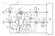
- the air conditioning system S includes a compressor 11, a heat exchanger 21, an expander 31, an expansion valve 41, and a water separation device 51.
- the compressor 11, the heat exchanger 21, the expander 31, the expansion valve 41, and the water separation device 51 are connected via the flow path in this order.
- the air conditioning system S includes an air cycle device 12 in which a compressor 11, a heat exchanger 21, and an expander 31 are connected in this order via a flow path.
- the air conditioning system S includes a first outside air introduction path 13, a first end of the first outside air introduction path 13 is connected to an inlet of the compressor 11, and a second end of the first outside air introduction path 13 is Open to the outdoors.
- the first air which is air
- the compressor 11 is connected to one end of the rotation shaft Ma of the motor M.
- the rotation shaft Ma is rotated to drive the compressor 11.
- An expander 31 is connected to the other end of the rotation shaft Ma. For this reason, the compressor 11 and the expander 31 are mutually connected by the common rotating shaft Ma.
- the air conditioning system S includes a first introduction path 14, one end of the first introduction path 14 is connected to the outlet of the compressor 11, and the other end of the first introduction path 14 is connected to the inlet of the heat exchanger 21.
- the heat exchanger 21 includes a heat radiation side channel 21a.
- the first introduction path 14 is connected to the inlet of the heat radiation side flow path 21a. The high-temperature first air after being compressed by the compressor 11 is introduced into the heat radiation side flow path 21a through the first introduction path 14.
- the heat exchanger 21 includes a heat absorption side flow path 21b arranged along the heat radiation side flow path 21a.
- the air conditioning system S includes a second outside air introduction path 25, one end of the second outside air introduction path 25 is connected to the inlet of the heat absorption side passage 21b, and the other end of the second outside air introduction path 25 is opened to the outdoors. is doing.
- the outdoor air as the second air is introduced into the heat absorption side passage 21b of the heat exchanger 21 through the second outside air introduction passage 25.
- the first air is cooled as a result of heat exchange between the first air flowing through the heat radiation side flow path 21a and the second air flowing through the heat absorption side flow path 21b.
- the air conditioning system S includes a second introduction path 15, one end of the second introduction path 15 is connected to the outlet of the heat radiation side passage 21 a, and the other end of the second introduction path 15 is connected to the inlet of the expander 31. It is connected.
- the first air after heat exchange with the second air in the heat exchanger 21 is sucked into the expander 31 via the second introduction path 15.
- the turbine of the expander 31 is driven by the first air after heat exchange, the first air is adiabatically expanded and the temperature of the first air is lowered.
- the compressor 11 is driven by the rotation of the motor M and the expansion work of the expansion turbine.
- the air conditioning system S includes a first outlet 16, one end of the first outlet 16 is connected to the outlet of the expander 31, and the other end of the first outlet 16 is opened indoors.
- An expansion valve 41 is disposed in the first lead-out path 16. In the expansion valve 41, the first air expanded by the expander 31 is further adiabatically expanded, and the temperature of the first air further decreases.
- the expansion valve 41 includes a spool 41 a that can adjust the flow passage cross-sectional area of the first outlet passage 16.
- the expansion ratio of the first air in the expander 31 can be controlled by adjusting the opening degree of the expansion valve 41 by the spool 41 a and adjusting the throttle amount of the first lead-out path 16.
- the expansion ratio of the 1st air in the expander 31 becomes small, so that the opening degree of the expansion valve 41 becomes small and the flow-path cross-sectional area of the 1st derivation
- the expansion ratio of the first air in the expander 31 increases as the opening degree of the expansion valve 41 increases and the flow passage cross-sectional area of the first outlet passage 16 increases.
- the air conditioning system S includes a water separation device 51 in the first outlet 16.
- the water separator 51 is disposed downstream of the expansion valve 41 in the direction in which the first air flows.
- the expansion valve 41 is integrated with the water separation device 51.
- the water separation device 51 separates moisture generated when the first air is expanded by the expansion valve 41 from the first air.
- the air conditioning system S includes a first cooling side switching valve 33 on the downstream side of the water separation device 51.
- the air conditioning system S includes a first discharge flow path 34, one end of the first discharge flow path 34 is connected to the first cooling side switching valve 33, and the other end of the first discharge flow path 34 is the outdoor Is open.
- the first cooling side switching valve 33 can be switched to the first position 33a or the second position 33b.
- the first position 33 a is a position that allows the first air to flow from the first outlet path 16 into the room and blocks the flow of the first air from the first outlet path 16 to the first discharge passage 34.
- the second position 33 b is a position that blocks the flow of the first air from the first lead-out path 16 into the room and allows the first air to flow from the first lead-out path 16 to the first discharge flow path 34.
- the air conditioning system S includes a second cooling side switching valve 61 on the first outside air introduction path 13.
- the air conditioning system S includes a first room air circulation channel 62, and a first end of the first room air circulation channel 62 is connected to the second cooling side switching valve 61, and the first room air circulation channel 62. The second end of the is open into the room.
- the second cooling side switching valve 61 can be switched to the first position 61a or the second position 61b.
- the first position 61 a is a position that allows room air to flow from the first inside air circulation flow path 62 to the compressor 11 and blocks the flow of outdoor air from the first outside air introduction path 13 to the compressor 11.
- the second position 61 b is a position that blocks the flow of room air from the first inside air circulation flow path 62 to the compressor 11 and allows the outside air to flow from the first outside air introduction path 13 to the compressor 11.
- the air conditioning system S includes a second outlet path 22, one end of the second outlet path 22 is connected to the outlet of the heat absorption side channel 21 b, and the other end of the second outlet path 22 opens into the room. .
- the second air whose temperature has risen due to heat exchange with the first air in the heat exchanger 21 flows from the heat absorption side passage 21b to the second outlet passage 22.
- the air conditioning system S includes a first heating side switching valve 23 in the second lead-out path 22.
- the air conditioning system S includes a second discharge flow path 24, one end of the second discharge flow path 24 is connected to the first heating-side switching valve 23, and the other end of the second discharge flow path 24 is the outdoor Is open.
- the first heating side switching valve 23 can be switched to the first position 23a or the second position 23b.
- the first position 23 a is a position that allows the second air to flow from the second outlet path 22 into the room and blocks the flow of the second air from the second outlet path 22 to the second discharge passage 24.
- the second position 23 b is a position that blocks the flow of the second air from the second lead-out path 22 into the room and allows the second air to flow from the second lead-out path 22 to the second discharge flow path 24.
- the air conditioning system S includes a second heating side switching valve 26 on the second outside air introduction path 25.
- the air conditioning system S includes a second inside air circulation passage 27, one end of the second inside air circulation passage 27 is connected to the second heating side switching valve 26, and the other end of the second inside air circulation passage 27. Is open into the room.
- the second heating side switching valve 26 can be switched to the first position 26a or the second position 26b.
- the first position 26a is a position that allows room air to flow from the second inside air circulation flow path 27 to the heat exchanger 21 and blocks the flow of outdoor air from the second outside air introduction path 25 to the heat exchanger 21. is there.
- the second position 26b is a position that blocks the flow of room air from the second inside air circulation flow path 27 to the heat exchanger 21 and allows outdoor air to flow from the second outside air introduction path 25 to the heat exchanger 21. It is.
- the air conditioning system S includes a hygrometer 28 as a humidity measuring device in the first outside air introduction path 13.
- the hygrometer 28 measures and grasps the humidity of the first air before being sucked into the compressor 11.
- the first air before being sucked into the compressor 11 is room air when the second cooling side switching valve 61 is switched to the first position 61a, and the second cooling side switching valve 61 is set to the second position 61b. If it is switched to, it is outdoor air.
- the air conditioning system S includes a thermometer 18 and a pressure gauge 19 on the downstream side of the expander 31 and on the upstream side of the expansion valve 41.
- the thermometer 18 measures the temperature of the first air immediately after being expanded by the expander 31.
- the pressure gauge 19 measures the pressure of the first air immediately after being expanded by the expander 31.
- the air conditioning system S includes a control device 29 that controls the drive of the motor M and the drive of the expansion valve 41.
- a thermometer 18, a pressure gauge 19 and a hygrometer 28 are connected to the control device 29.
- a signal including the measurement results output from the thermometer 18, the pressure gauge 19 and the hygrometer 28 is input to the control device 29.
- the control device 29 grasps the humidity of the first air measured by the hygrometer 28 and adjusts the rotation speed of the motor M and the opening degree of the expansion valve 41 according to the humidity of the first air.
- the desired expansion ratio of the first air is an expansion ratio when the humidity of the first air is less than 100% according to the temperature and pressure when the first air is expanded by the expander 31. This is because when the first air expands in the expander 31, the humidity of the first air becomes 100% or more and dew condensation is prevented from occurring in the expander 31.
- the temperature when the first air is expanded by the expander 31 is measured by the thermometer 18, and the pressure is measured by the pressure gauge 19.
- the humidity of the first air before being sucked into the compressor 11, the temperature and pressure of the first air in the expander 31, the rotation speed of the motor M, and the opening degree of the expansion valve 41 are set.
- the associated table is stored. The relationship among the humidity, pressure and temperature, the number of rotations of the motor M, and the expansion valve 41 is measured and correlated in advance through experiments or the like.
- the air conditioning system S includes a bypass passage 35 that connects the second introduction passage 15 and the first lead-out passage 16 and bypasses the expander 31.
- the air conditioning system S includes a flow rate control valve 36 in the bypass flow path 35.
- the flow rate control valve 36 can control the flow rate of the first air flowing through the bypass flow path 35.
- the flow control valve 36 is connected to the control device 29.
- the control device 29 can control the opening degree of the flow control valve 36.
- the control device 29 grasps the humidity of the first air before being sucked into the compressor 11 from the measurement result of the hygrometer 28.
- the control apparatus 29 controls the opening degree of the flow control valve 36 according to the humidity of 1st air, and adjusts the opening degree of the bypass flow path 35.
- the control device 29 increases the opening degree of the flow control valve 36 so as to reduce the amount of the first air sucked into the expander 31.
- the control device 29 controls the flow rate control valve 36 so as not to decrease the amount of the first air sucked into the expander 31 by reducing the opening degree of the flow control valve 36.
- the control device 29 stores a table in which the humidity and the opening degree of the flow control valve 36 are associated with each other. The relationship between the humidity and the opening degree of the flow control valve 36 is measured and correlated in advance through experiments or the like.
- the first cooling side switching valve 33 is switched to the first position 33a.
- the second cooling side switching valve 61 is switched to the first position 61a
- indoor air is introduced and cooling is performed by circulating the internal air.
- the second cooling-side switching valve 61 is switched to the second position 61b
- outdoor air is introduced and cooling by outdoor air circulation is performed.
- the first heating side switching valve 23 is switched to the second position 23b so that the second air after the heat exchange is performed in the heat exchanger 21 does not flow into the room.
- the 2nd heating side switching valve 26 is switched to the 1st position 26a, indoor air is introduce
- the second heating side switching valve 26 is switched to the second position 26b, the outdoor air is introduced as the second air and cooling is performed.
- the first air When performing cooling, when the first air is sucked into the compressor 11, it is compressed by the compressor 11 to become high-temperature air.
- the high-temperature air that has flowed out of the compressor 11 flows into the heat radiation side passage 21a of the heat exchanger 21 and is cooled by the second air that flows through the heat absorption side passage 21b.
- the cooled first air flows out of the heat exchanger 21 and is then sucked into the expander 31 to expand. As a result, the temperature of the first air further decreases.
- the temperature of the first air decreases as the first air passes through the heat exchanger 21 and the expander 31.
- the hygrometer 28 measures the humidity of the first air before being sucked into the compressor 11.
- the control device 29 adjusts the rotation of the motor M and the opening degree of the expansion valve 41 according to the temperature and pressure of the first air after being expanded by the expander 31 to obtain the humidity of the first air before compression.
- the first air is expanded at a corresponding expansion ratio. More specifically, the first air is expanded to a position before a portion of the water vapor contained in the first air becomes condensed water.
- the control device 29 controls the opening degree of the flow rate control valve 36 according to the humidity of the first air before being sucked into the compressor 11, and the first sucked into the expander 31 from the second introduction path 15. Adjust the amount of air.
- the temperature of the first air expanded by the expander 31 further decreases when the first air is sucked into the expansion valve 41 and expanded. At this time, the water vapor contained in the first air is condensed to become condensed water.
- the condensed water is separated from the first air in the water separation device 51.
- the first air after the water separation passes through the first cooling side switching valve 33 and is supplied into the room from the first lead-out path 16 to cool the room.
- the second air heat-exchanged by the heat exchanger 21 is discharged from the second discharge flow path 24 to the outside through the first heating side switching valve 23.
- the first heating side switching valve 23 is switched to the first position 23a. Further, the first cooling side switching valve 33 is switched to the second position 33b. At this time, when the second cooling side switching valve 61 is switched to the first position 61a, room air is introduced and heating by the inside air circulation is performed. On the other hand, when the second cooling side switching valve 61 is switched to the second position 61b, outdoor air is introduced and heating is performed. At this time, when the second heating side switching valve 26 is switched to the first position 26a, the room air circulated in the room air is used as the second air. When the second heating side switching valve 26 is switched to the second position 26b, outdoor air is used as the second air.
- the control device 29 controls the number of rotations of the motor M and the opening degree of the expansion valve 41, so that dew condensation in the expander 31 is suppressed.
- the second air warmed by the heat exchange performed by the heat exchanger 21 is supplied to the room through the first heating side switching valve 23 and heats the room.
- the air conditioning system S includes a motor M for driving the expander 31, an expansion valve 41 disposed on the downstream side of the expander 31, a control device 29 for controlling the motor M and the expansion valve 41, and a hygrometer. 28.
- the control device 29 controls the rotational speed of the motor M and the opening degree of the expansion valve 41 based on the humidity of the first air before being sucked into the compressor 11 so that the expander 31 does not generate condensed water. Then, the expansion in the expander 31 is controlled. For this reason, it is possible to suppress the occurrence of dew condensation on the turbine when the first air expands in the expander 31, and to suppress damage to the turbine due to moisture.
- the expansion valve 41 is integrated with the water separation device 51. For this reason, the first air flows into the water separator 51 immediately after being expanded by the expansion valve 41. Therefore, the water separation device 51 can quickly separate water from the first air immediately after the expansion of the first air.
- the air conditioning system S includes a bypass channel 35.
- the first air after the heat exchange is performed by the heat exchanger 21 flows through the bypass flow path 35, and is supplied to the expansion valve 41 while avoiding the expander 31. For this reason, the amount of the first air sucked into the expander 31 can be reduced, and the amount of the first air sucked into the expansion valve 41 can be increased. Thereby, generation
- the air conditioning system S includes a second cooling-side switching valve 61 in the first outside air introduction path 13.
- a first inside air circulation channel 62 is connected to the second cooling side switching valve 61.
- the above embodiment may be modified as follows. Based on a table in which the rotational speed of the motor M, the opening degree of the expansion valve 41, the humidity of the first air, and the pressure and temperature in the expander 31 are associated with each other, the control device 29 Although the rotation speed of the motor M and the opening degree of the expansion valve 41 are controlled so that the humidity of one air does not become 100% or more, it is not limited to this.
- the control device 29 may calculate and determine the rotation speed of the motor M and the opening degree of the expansion valve 41 from the humidity of the first air and the pressure and temperature in the expander 31.
- the hygrometer 28 is provided near the inlet of the compressor 11 and the humidity of the first air before being sucked into the compressor 11 is measured, the present invention is not limited to this.
- a hygrometer 28 is provided near the outlet of the compressor 11 and the inlet of the expander 31, and from the humidity of the first air immediately after compression by the compressor 11 and the humidity of the first air before being expanded by the expander 31, You may determine the rotation speed of the motor M, and the opening degree of the expansion valve 41.
- thermometer 28 is embodied as a humidity measuring device
- the humidity measuring device may be changed to a thermometer and a control device 29.
- thermometers are provided in the vicinity of the inlet of the compressor 11, in the vicinity of the outlet of the compressor 11, in the vicinity of the inlet of the expander 31, and the like, and are expanded by the temperature of the first air before and after compression by the compressor 11
- the humidity may be estimated and grasped by the control device 29 from the temperature of the first air before the air flow.
- the expansion valve 41 may be a fixed throttle. In this case, since the opening degree of the expansion valve 41 cannot be controlled, the control device 29 may control the rotation speed of the motor M so that the humidity of the first air in the expander 31 is less than 100%.
- the motor M may be a motor having a constant rotational speed.
- the control device 29 may control the opening degree of the expansion valve 41 so that the humidity of the first air in the expander 31 is less than 100%.
- the expansion valve 41 may be separate from the water separation device 51.
- the expansion valve 41 may be connected to the water separation device 51 via a flow path.
- the first air supplied into the room from the first lead-out path 16 may be reheated by waste heat from the engine and the temperature may be adjusted.
Landscapes
- Engineering & Computer Science (AREA)
- Physics & Mathematics (AREA)
- Mechanical Engineering (AREA)
- Thermal Sciences (AREA)
- General Engineering & Computer Science (AREA)
- Air Conditioning Control Device (AREA)
Abstract
空気調和システムは、圧縮機及び膨張機が連結された回転軸を回転させるモータと、膨張弁と、膨張弁で膨張した第1空気中の水分を分離する水分離装置と、圧縮機に流入する前の第1空気の湿度を測定する湿度計とを備える。また、空気調和システムは、制御装置を備える。制御装置は、膨張機での第1空気の湿度が100%未満となるように、湿度計の測定結果に基づいて、モータの回転数と膨張弁の開度とを制御する。
Description
本発明は、空気サイクル装置を含む空気調和システムに関する。
近年、地球環境問題への関心が高まり、自然環境に対するフロン系冷媒の影響が懸念されている。そのため、空気を冷媒として用いる空気サイクル装置を利用した空気調和システムが採用されている。
空気調和システムの空気サイクル装置では、空気が圧縮機に吸い込まれて断熱圧縮されることで、空気の温度が上昇する。圧縮機から吐出された高温空気は、熱交換器で冷却されてから、膨張機に吸い込まれる。すると、空気は、膨張機で断熱膨張し、温度が低下することで、低温空気となる。室内の冷房時には、低温空気が室内に供給され、室内の暖房時には、低温空気がリヒートされてから室内に供給される。
このような空気サイクル装置では、冷却時や膨張時に、空気中の水蒸気が凝縮し、凝縮水が発生する。例えば、特許文献1に開示の空気調和システムは、水分離器を用いて、圧縮後の冷却により凝縮した空気中の水分を除去する。
ところが、特許文献1の空気調和システムでは、水分離器により水分を除去するが、膨張機に吸い込まれた空気中に水蒸気が含まれていると、空気の膨張時に水蒸気が凝縮し、膨張機のタービンに結露が発生しやすくなる。その結果、タービンが損傷しやすくなる。
本発明の目的は、膨張機での結露の発生を抑制することができる空気調和システムを提供することにある。
上記問題点を解決するため、本願発明の第一の態様によれば、空気を圧縮する圧縮機、圧縮された空気との間で熱交換を行う熱交換器、及び熱交換器で熱交換が行われた後の空気を膨張させる膨張機を含む空気サイクル装置と、膨張機で膨張した空気を膨張させる膨張弁と、圧縮機及び膨張機が連結された回転軸を回転させるモータと、膨張弁で膨張した空気から水分を分離する水分離装置と、膨張機で膨張する前の空気の湿度を把握するための湿度計測装置と、膨張機で膨張した空気の湿度が100%未満となるように、湿度計測装置で把握した湿度に基づいて、モータの回転数及び膨張弁の開度の少なくとも一方を制御する制御装置とを有する空気調和システムが提供される。
これによれば、空気は、圧縮機で圧縮されてから、熱交換器で熱交換が行われた後、膨張機で膨張する。このとき、制御装置は、膨張機で膨張した空気の湿度が100%未満となるように、モータの回転数及び膨張弁の開度の少なくとも一方を制御し、膨張機での空気の膨張量を制御する。このため、空気が膨張機で膨張し、温度及び圧力が低下しても、空気に含まれる水蒸気が凝縮することを抑制できる。よって、膨張機のタービンに結露が発生することを抑制できる。
以下、本発明の空気調和システムを具体化した一実施形態を図1~図3にしたがって説明する。
図1又は図2に示すように、空気調和システムSは、室内の冷房又は暖房を行う。空気調和システムSは、圧縮機11、熱交換器21、膨張機31、膨張弁41及び水分離装置51を備えている。圧縮機11、熱交換器21、膨張機31、膨張弁41及び水分離装置51は、この順で流路を介して接続されている。空気調和システムSは、圧縮機11と熱交換器21と膨張機31とをこの順で流路を介して接続した空気サイクル装置12を備えている。
図1又は図2に示すように、空気調和システムSは、室内の冷房又は暖房を行う。空気調和システムSは、圧縮機11、熱交換器21、膨張機31、膨張弁41及び水分離装置51を備えている。圧縮機11、熱交換器21、膨張機31、膨張弁41及び水分離装置51は、この順で流路を介して接続されている。空気調和システムSは、圧縮機11と熱交換器21と膨張機31とをこの順で流路を介して接続した空気サイクル装置12を備えている。
空気調和システムSは、第1外気導入路13を備え、第1外気導入路13の第1端部は、圧縮機11の入口に接続され、第1外気導入路13の第2端部は、室外に開口している。空気調和システムSでは、圧縮機11の駆動により、空気である第1空気が、第1外気導入路13を介して圧縮機11に吸入される。圧縮機11は、モータMの回転軸Maの一端に連結されている。モータMが駆動すると、回転軸Maが回転して、圧縮機11を駆動させる。回転軸Maの他端には、膨張機31が連結されている。このため、圧縮機11と膨張機31とは、共通の回転軸Maによって互いに連結されている。
空気調和システムSは、第1導入路14を備え、第1導入路14の一端は、圧縮機11の出口に接続され、第1導入路14の他端は、熱交換器21の入口に接続されている。熱交換器21は、放熱側流路21aを備えている。放熱側流路21aの入口には、第1導入路14が接続されている。圧縮機11で圧縮された後の高温の第1空気は、第1導入路14を介して放熱側流路21aに導入される。
熱交換器21は、放熱側流路21aに沿って配置された吸熱側流路21bを備えている。空気調和システムSは、第2外気導入路25を備え、第2外気導入路25の一端は、吸熱側流路21bの入口に接続され、第2外気導入路25の他端は、室外に開口している。第2空気としての室外空気は、第2外気導入路25を介して熱交換器21の吸熱側流路21bに導入される。熱交換器21では、放熱側流路21aを流れる第1空気と吸熱側流路21bを流れる第2空気との間で熱交換が行われた結果、第1空気が冷却される。
空気調和システムSは、第2導入路15を備え、第2導入路15の一端は、放熱側流路21aの出口に接続され、第2導入路15の他端は、膨張機31の入口に接続されている。熱交換器21で第2空気との間で熱交換が行われた後の第1空気は、第2導入路15を介して膨張機31に吸い込まれる。そして、熱交換後の第1空気によって膨張機31のタービンが駆動されると、第1空気が断熱膨張し、第1空気の温度が下がる。このとき、圧縮機11は、モータMの回転と膨張タービンの膨張仕事とによって駆動される。
空気調和システムSは、第1導出路16を備え、第1導出路16の一端は、膨張機31の出口に接続され、第1導出路16の他端は、室内に開口している。第1導出路16には、膨張弁41が配置されている。膨張弁41では、膨張機31で膨張した第1空気がさらに断熱膨張し、第1空気の温度がさらに低下する。
図3に示すように、膨張弁41は、第1導出路16の流路断面積を調節可能なスプール41aを備えている。スプール41aによって膨張弁41の開度を調節し、第1導出路16の絞り量を調節することで、膨張機31での第1空気の膨張比を制御可能である。膨張弁41の開度が小さくなり、第1導出路16の流路断面積が小さくなるほど、膨張機31での第1空気の膨張比が小さくなる。一方、膨張弁41の開度が大きくなり、第1導出路16の流路断面積が大きくなるほど、膨張機31での第1空気の膨張比が大きくなる。
空気調和システムSは、第1導出路16に水分離装置51を備えている。水分離装置51は、膨張弁41に対して、第1空気が流れる方向の下流側に配置されている。膨張弁41は、水分離装置51に一体化されている。水分離装置51は、膨張弁41で第1空気が膨張した際に発生した水分を、第1空気から分離する。
図1に示すように、空気調和システムSは、水分離装置51の下流側に第1冷房側切換弁33を備えている。また、空気調和システムSは、第1排出流路34を備え、第1排出流路34の一端は、第1冷房側切換弁33に接続され、第1排出流路34の他端は、室外に開口している。第1冷房側切換弁33は、第1位置33a又は第2位置33bに切り換え可能である。第1位置33aは、第1導出路16から室内へ第1空気が流れることを許容しかつ第1導出路16から第1排出流路34への第1空気の流れを遮断する位置である。第2位置33bは、第1導出路16から室内への第1空気の流れを遮断しかつ第1導出路16から第1排出流路34へ第1空気が流れることを許容する位置である。
空気調和システムSは、第1外気導入路13上に第2冷房側切換弁61を備えている。また、空気調和システムSは、第1内気循環流路62を備え、第1内気循環流路62の第1端部は、第2冷房側切換弁61に接続され、第1内気循環流路62の第2端部は、室内に開口している。第2冷房側切換弁61は、第1位置61a又は第2位置61bに切り換え可能である。第1位置61aは、第1内気循環流路62から圧縮機11へ室内空気が流れることを許容しかつ第1外気導入路13から圧縮機11への室外空気の流れを遮断する位置である。第2位置61bは、第1内気循環流路62から圧縮機11への室内空気の流れを遮断しかつ第1外気導入路13から圧縮機11へ室外空気が流れることを許容する位置である。
空気調和システムSは、第2導出路22を備え、第2導出路22の一端は、吸熱側流路21bの出口に接続され、第2導出路22の他端は、室内に開口している。熱交換器21で第1空気との間で熱交換が行われて温度が上昇した第2空気は、吸熱側流路21bから第2導出路22に流れる。
空気調和システムSは、第2導出路22に第1暖房側切換弁23を備えている。また、空気調和システムSは、第2排出流路24を備え、第2排出流路24の一端は、第1暖房側切換弁23に接続され、第2排出流路24の他端は、室外に開口している。第1暖房側切換弁23は、第1位置23a又は第2位置23bに切り換え可能である。第1位置23aは、第2導出路22から室内へ第2空気が流れることを許容しかつ第2導出路22から第2排出流路24への第2空気の流れを遮断する位置である。第2位置23bは、第2導出路22から室内への第2空気の流れを遮断しかつ第2導出路22から第2排出流路24へ第2空気が流れることを許容する位置である。
空気調和システムSは、第2外気導入路25上に第2暖房側切換弁26を備えている。また、空気調和システムSは、第2内気循環流路27を備え、第2内気循環流路27の一端は、第2暖房側切換弁26に接続され、第2内気循環流路27の他端は、室内に開口している。第2暖房側切換弁26は、第1位置26a又は第2位置26bに切り換え可能である。第1位置26aは、第2内気循環流路27から熱交換器21へ室内空気が流れることを許容しかつ第2外気導入路25から熱交換器21への室外空気の流れを遮断する位置である。第2位置26bは、第2内気循環流路27から熱交換器21への室内空気の流れを遮断し、かつ第2外気導入路25から熱交換器21へ室外空気が流れることを許容する位置である。
空気調和システムSは、第1外気導入路13に湿度計測装置としての湿度計28を備えている。湿度計28は、圧縮機11に吸入される前の第1空気の湿度を測定し、把握する。圧縮機11に吸入される前の第1空気は、第2冷房側切換弁61が第1位置61aに切り換えられている場合は室内空気であり、第2冷房側切換弁61が第2位置61bに切り換えられている場合は室外空気である。
また、空気調和システムSは、膨張機31の下流側でかつ膨張弁41より上流側に、温度計18及び圧力計19を備えている。温度計18は、膨張機31で膨張した直後の第1空気の温度を測定する。圧力計19は、膨張機31で膨張した直後の第1空気の圧力を測定する。
また、空気調和システムSは、モータMの駆動及び膨張弁41の駆動を制御する制御装置29を備えている。制御装置29には、温度計18、圧力計19及び湿度計28が接続されている。制御装置29には、温度計18、圧力計19及び湿度計28から出力された測定結果を含む信号が入力される。
制御装置29は、湿度計28が測定した第1空気の湿度を把握し、第1空気の湿度に応じてモータMの回転数及び膨張弁41の開度をそれぞれ調節する。制御装置29によって、モータMの回転数及び膨張弁41の開度を制御することで、膨張機31での第1空気の膨張比を所望の値にコントロールする。第1空気の所望の膨張比は、膨張機31で第1空気が膨張した際の温度及び圧力に応じて第1空気の湿度が100%未満となるときの膨張比である。これは、膨張機31で第1空気が膨張した際、第1空気の湿度が100%以上になって膨張機31で結露が発生するのを抑制するためである。膨張機31で第1空気が膨張した際の温度は、温度計18により測定され、圧力は、圧力計19により測定される。
制御装置29には、圧縮機11に吸入される前の第1空気の湿度と、膨張機31での第1空気の温度及び圧力と、モータMの回転数及び膨張弁41の開度とを対応付けたテーブルが記憶されている。湿度と、圧力及び温度と、モータMの回転数及び膨張弁41との関係は、実験等によって予め測定され、対応付けられている。
空気調和システムSは、第2導入路15と第1導出路16とを接続しかつ膨張機31をバイパスするバイパス流路35を備えている。また、空気調和システムSは、バイパス流路35に流量制御弁36を備えている。流量制御弁36は、バイパス流路35を流れる第1空気の流量を制御可能である。流量制御弁36は、制御装置29に接続されている。制御装置29は、流量制御弁36の開度を制御可能である。制御装置29は、湿度計28の測定結果から、圧縮機11に吸入される前の第1空気の湿度を把握する。そして、制御装置29は、第1空気の湿度に応じて、流量制御弁36の開度を制御し、バイパス流路35の開度を調節する。
第1空気の湿度が高いほど、制御装置29は、流量制御弁36の開度を大きくして、膨張機31に吸い込まれる第1空気の量を減らすように制御する。一方、第1空気の湿度が低いほど、制御装置29は、流量制御弁36の開度を小さくして、膨張機31に吸い込まれる第1空気の量を減らさないように制御する。制御装置29には、湿度と流量制御弁36の開度とを対応付けたテーブルが記憶されている。湿度と流量制御弁36の開度との関係は、実験等によって予め測定され、対応付けられている。
室内の冷房を行う際、第1冷房側切換弁33が第1位置33aに切り換えられる。このとき、第2冷房側切換弁61が第1位置61aに切り換えられると、室内空気が導入されて、内気循環による冷房が行われる。一方、第2冷房側切換弁61が第2位置61bに切り換えられると、室外空気が導入されて、外気循環による冷房が行われる。また、このとき、熱交換器21で熱交換が行われた後の第2空気を室内へ流入させないようにするため、第1暖房側切換弁23が第2位置23bに切り換えられる。さらに、第2暖房側切換弁26が第1位置26aに切り換えられると、室内空気が第2空気として導入されて、内気循環による冷房が行われる。一方、第2暖房側切換弁26が第2位置26bに切り換えられると、室外空気が第2空気として導入されて、冷房が行われる。
冷房を行う際、第1空気は、圧縮機11に吸入されると、圧縮機11により圧縮されて高温空気となる。圧縮機11から流出した高温空気は、熱交換器21の放熱側流路21aに流入し、吸熱側流路21bを流れる第2空気によって冷却される。冷却された第1空気は、熱交換器21から流出した後、膨張機31に吸い込まれて、膨張する。その結果、第1空気の温度は、更に低下する。
このように、第1空気の温度は、第1空気が熱交換器21及び膨張機31を通過することで、低下する。本実施形態において、湿度計28は、圧縮機11に吸入される前の第1空気の湿度を測定する。また、制御装置29は、膨張機31で膨張した後の第1空気の温度及び圧力に応じて、モータMの回転及び膨張弁41の開度を調節し、圧縮前の第1空気の湿度に応じた膨張比で、第1の空気を膨張させる。より具体的には、第1の空気は、第1空気に含まれていた水蒸気の一部が凝縮水となる手前まで、膨張させられる。また、制御装置29は、圧縮機11に吸入される前の第1空気の湿度に応じて、流量制御弁36の開度を制御し、第2導入路15から膨張機31に吸い込まれる第1空気の量を調節する。
膨張機31で膨張した第1空気の温度は、第1空気が膨張弁41に吸い込まれて膨張すると、更に低下する。このとき、第1空気に含まれていた水蒸気は、凝縮して凝縮水となる。この凝縮水は、水分離装置51において、第1空気から分離される。水分離後の第1空気は、第1冷房側切換弁33を通過して第1導出路16から室内に供給され、室内を冷却する。また、熱交換器21で熱交換された第2空気は、第1暖房側切換弁23を介して第2排出流路24から室外に排出される。
図2に示すように、室内の暖房を行う際、第1暖房側切換弁23が第1位置23aに切り換えられる。また、第1冷房側切換弁33が第2位置33bに切り換えられる。このとき、第2冷房側切換弁61が第1位置61aに切り換えられると、室内空気が導入されて、内気循環による暖房が行われる。一方、第2冷房側切換弁61が第2位置61bに切り換えられると、室外空気が導入されて、暖房が行われる。また、このとき、第2暖房側切換弁26が第1位置26aに切り換えられると、内気循環させられた室内空気が第2空気として使用される。第2暖房側切換弁26が第2位置26bに切り換えられると、室外空気が第2空気として使用される。
暖房を行う際、第1空気は、圧縮機11に取り込まれると、圧縮機11により圧縮されて高温空気となる。圧縮機11から流出した高温空気は、熱交換器21の放熱側流路21aに流入し、吸熱側流路21bを流れる第2空気によって冷却される。冷却された第1空気は、熱交換器21から流出した後、膨張機31に吸い込まれて、膨張する。その結果、第1の空気の温度は、更に低下する。暖房の際も、膨張機31では、第1空気の膨張が行われる。このときも、制御装置29がモータMの回転数、膨張弁41の開度を制御することで、膨張機31での結露が抑制される。熱交換器21で熱交換が行われたことにより暖められた第2空気は、第1暖房側切換弁23を介して室内に供給され、室内を加熱する。
上記実施形態によれば、以下のような効果を得ることができる。
(1)空気調和システムSは、膨張機31を駆動させるモータMと、膨張機31の下流側に配置された膨張弁41と、モータM及び膨張弁41を制御する制御装置29と、湿度計28とを備えている。制御装置29は、膨張機31で凝縮水を発生させないように、圧縮機11に吸入される前の第1空気の湿度に基づいて、モータMの回転数と膨張弁41の開度とを制御し、膨張機31での膨張を制御する。このため、膨張機31での第1空気の膨張時にタービンに結露が発生することを抑制し、水分によるタービンの損傷を抑制できる。
(1)空気調和システムSは、膨張機31を駆動させるモータMと、膨張機31の下流側に配置された膨張弁41と、モータM及び膨張弁41を制御する制御装置29と、湿度計28とを備えている。制御装置29は、膨張機31で凝縮水を発生させないように、圧縮機11に吸入される前の第1空気の湿度に基づいて、モータMの回転数と膨張弁41の開度とを制御し、膨張機31での膨張を制御する。このため、膨張機31での第1空気の膨張時にタービンに結露が発生することを抑制し、水分によるタービンの損傷を抑制できる。
(2)膨張弁41は、水分離装置51に一体化されている。このため、第1空気は、膨張弁41で膨張した直後に、水分離装置51に流入する。よって、水分離装置51は、第1空気の膨張直後、速やかに、第1空気から水分を分離することができる。
(3)空気調和システムSは、バイパス流路35を備えている。熱交換器21で熱交換が行われた後の第1空気は、バイパス流路35を流れることで、膨張機31を避けて、膨張弁41に供給される。このため、膨張機31に吸い込まれる第1空気の量を減らして、膨張弁41に吸い込まれる第1空気の量を増やすことができる。これにより、膨張機31での凝縮水の発生を、より一層抑制することができる。また、膨張弁41で膨張により凝縮水を発生させることで、膨張機31での結露を効果的に抑制することができる。
(4)空気調和システムSは、第1外気導入路13に第2冷房側切換弁61を備えている。第2冷房側切換弁61には、第1内気循環流路62が接続されている。第2冷房側切換弁61が第1位置61aに切り換えられると、室内空気を第1空気として圧縮機11に導入することができる。このため、室外空気の湿度が高い場合、室内空気を第1空気として導入することで、膨張機31での凝縮水の発生を効果的に抑制することができる。
(5)空気調和システムSでは、第1空気が膨張機31で膨張し、膨張弁41でさらに膨張した後、水分離装置51で第1空気から水分が分離される。このため、冷房時には、乾燥した空気を室内に供給することができる。
上記実施形態は、以下のように変更してもよい。
制御装置29は、モータMの回転数及び膨張弁41の開度と、第1空気の湿度と、膨張機31での圧力及び温度とを対応付けたテーブルに基づいて、膨張機31での第1空気の湿度が100%以上にならないようにモータMの回転数及び膨張弁41の開度を制御したが、これに限らない。制御装置29は、第1空気の湿度と、膨張機31での圧力及び温度とから、モータMの回転数及び膨張弁41の開度を演算し、決定してもよい。
制御装置29は、モータMの回転数及び膨張弁41の開度と、第1空気の湿度と、膨張機31での圧力及び温度とを対応付けたテーブルに基づいて、膨張機31での第1空気の湿度が100%以上にならないようにモータMの回転数及び膨張弁41の開度を制御したが、これに限らない。制御装置29は、第1空気の湿度と、膨張機31での圧力及び温度とから、モータMの回転数及び膨張弁41の開度を演算し、決定してもよい。
湿度計28を圧縮機11の入口付近に設け、圧縮機11に吸入される前の第1空気の湿度を測定したが、これに限らない。圧縮機11の出口付近や膨張機31の入口付近に湿度計28を設け、圧縮機11による圧縮直後の第1空気の湿度や、膨張機31で膨張される前の第1空気の湿度から、モータMの回転数及び膨張弁41の開度を決定してもよい。
湿度計測装置として湿度計28に具体化したが、湿度計測装置を温度計及び制御装置29に変更してもよい。この場合、温度計を圧縮機11の入口付近、圧縮機11の出口付近、膨張機31の入口付近等に設け、圧縮機11による圧縮前後の第1空気の温度や、膨張機31で膨張される前の第1空気の温度から、制御装置29で湿度を推測し、把握してもよい。
膨張弁41は固定絞りであってもよい。この場合、膨張弁41の開度は制御できないため、制御装置29は、膨張機31での第1空気の湿度が100%未満となるように、モータMの回転数を制御すればよい。
モータMは、回転数が一定であるタイプのモータであってもよい。この場合、制御装置29は、膨張機31での第1空気の湿度が100%未満となるように、膨張弁41の開度を制御すればよい。
膨張弁41は、水分離装置51と別体でもよい。また、膨張弁41は、流路を介して水分離装置51に接続されてもよい。
第1導出路16から室内に供給される第1空気は、エンジンからの廃熱によってリヒートされて、温度調節されてもよい。
第1導出路16から室内に供給される第1空気は、エンジンからの廃熱によってリヒートされて、温度調節されてもよい。
Claims (6)
- 空気調和システムであって、
空気を圧縮する圧縮機、圧縮された前記空気との間で熱交換を行う熱交換器、及び前記熱交換器で熱交換が行われた後の前記空気を膨張させる膨張機を含む空気サイクル装置と、
前記膨張機で膨張した前記空気を膨張させる膨張弁と、
前記圧縮機及び前記膨張機が連結された回転軸を回転させるモータと、
前記膨張弁で膨張した前記空気から水分を分離する水分離装置と、
前記膨張機で膨張する前の前記空気の湿度を把握するための湿度計測装置と、
前記膨張機で膨張した前記空気の湿度が100%未満となるように、前記湿度計測装置で把握した湿度に基づいて、前記モータの回転数及び前記膨張弁の開度の少なくとも一方を制御する制御装置と
を有する、空気調和システム。 - 請求項1に記載の空気調和システムにおいて、
前記膨張弁は、前記水分離装置に一体化されている、空気調和システム。 - 請求項1又は2に記載の空気調和システムにおいて、
前記熱交換器と前記膨張機とを繋ぐ流路と、前記膨張機と前記膨張弁とを繋ぐ流路とは、バイパス流路によって互いに接続されている、空気調和システム。 - 請求項3に記載の空気調和システムにおいて、
前記バイパス流路には、流量制御弁が配置されている、空気調和システム。 - 請求項1~4のうちいずれか一項に記載の空気調和システムにおいて、
前記圧縮機に流入する空気は、室内空気である、空気調和システム。 - 請求項1~5のうちいずれか一項に記載の空気調和システムは、更に、
前記圧縮機の入口に接続される第1端部、及び室外に開口している第2端部を有する外気導入路と、
前記第1外気導入路上に設けられ、第1位置又は第2位置に切り換え可能な冷房側切換弁と、
前記冷房側切換弁に接続される第1端部、及び室内に開口している第2端部を有する内気循環流路とを備え、
前記冷房側切換弁は、前記第1位置に切り換えられると、前記内気循環流路から前記圧縮機へ室内空気が流れることを許容しかつ前記外気導入路から前記圧縮機への室外空気の流れを遮断し、
前記冷房側切換弁は、前記第2位置に切り換えられると、前記内気循環流路から前記圧縮機への室内空気の流れを遮断しかつ前記外気導入路から前記圧縮機へ室外空気が流れることを許容する、空気調和システム。
Applications Claiming Priority (2)
| Application Number | Priority Date | Filing Date | Title |
|---|---|---|---|
| JP2015030686A JP2016151408A (ja) | 2015-02-19 | 2015-02-19 | 空気調和システム |
| JP2015-030686 | 2015-02-19 |
Publications (1)
| Publication Number | Publication Date |
|---|---|
| WO2016132820A1 true WO2016132820A1 (ja) | 2016-08-25 |
Family
ID=56692457
Family Applications (1)
| Application Number | Title | Priority Date | Filing Date |
|---|---|---|---|
| PCT/JP2016/052002 Ceased WO2016132820A1 (ja) | 2015-02-19 | 2016-01-25 | 空気調和システム |
Country Status (2)
| Country | Link |
|---|---|
| JP (1) | JP2016151408A (ja) |
| WO (1) | WO2016132820A1 (ja) |
Cited By (1)
| Publication number | Priority date | Publication date | Assignee | Title |
|---|---|---|---|---|
| CN114857695A (zh) * | 2022-05-24 | 2022-08-05 | 河北工业大学 | 新风与回风独立处理的空调系统及其控制方法 |
Families Citing this family (2)
| Publication number | Priority date | Publication date | Assignee | Title |
|---|---|---|---|---|
| JP6955181B2 (ja) * | 2019-12-19 | 2021-10-27 | 三菱重工冷熱株式会社 | 空気冷媒サイクルを用いた冷却装置 |
| CN112325504A (zh) * | 2020-11-03 | 2021-02-05 | 珠海格力电器股份有限公司 | 空调 |
Citations (4)
| Publication number | Priority date | Publication date | Assignee | Title |
|---|---|---|---|---|
| JPH05223375A (ja) * | 1992-02-07 | 1993-08-31 | Mitsubishi Heavy Ind Ltd | エアサイクル空気調和装置 |
| JPH11101520A (ja) * | 1997-09-29 | 1999-04-13 | Sharp Corp | エアサイクル式空気調和装置 |
| WO2000073713A1 (en) * | 1997-12-17 | 2000-12-07 | Svenska Rotor Maskiner Ab | Method and means for controlling the generation of cold air |
| JP2003139425A (ja) * | 2001-11-02 | 2003-05-14 | Daikin Ind Ltd | 空気調和装置 |
-
2015
- 2015-02-19 JP JP2015030686A patent/JP2016151408A/ja active Pending
-
2016
- 2016-01-25 WO PCT/JP2016/052002 patent/WO2016132820A1/ja not_active Ceased
Patent Citations (4)
| Publication number | Priority date | Publication date | Assignee | Title |
|---|---|---|---|---|
| JPH05223375A (ja) * | 1992-02-07 | 1993-08-31 | Mitsubishi Heavy Ind Ltd | エアサイクル空気調和装置 |
| JPH11101520A (ja) * | 1997-09-29 | 1999-04-13 | Sharp Corp | エアサイクル式空気調和装置 |
| WO2000073713A1 (en) * | 1997-12-17 | 2000-12-07 | Svenska Rotor Maskiner Ab | Method and means for controlling the generation of cold air |
| JP2003139425A (ja) * | 2001-11-02 | 2003-05-14 | Daikin Ind Ltd | 空気調和装置 |
Cited By (2)
| Publication number | Priority date | Publication date | Assignee | Title |
|---|---|---|---|---|
| CN114857695A (zh) * | 2022-05-24 | 2022-08-05 | 河北工业大学 | 新风与回风独立处理的空调系统及其控制方法 |
| CN114857695B (zh) * | 2022-05-24 | 2024-04-12 | 河北工业大学 | 新风与回风独立处理的空调系统及其控制方法 |
Also Published As
| Publication number | Publication date |
|---|---|
| JP2016151408A (ja) | 2016-08-22 |
Similar Documents
| Publication | Publication Date | Title |
|---|---|---|
| CN106225116B (zh) | 一种基于热泵热回收及双蒸发温度的高效新风除湿机 | |
| US10502468B2 (en) | Parallel capillary expansion tube systems and methods | |
| US20170030601A1 (en) | Hvac unit with hot gas reheat | |
| CN104633837B (zh) | 空调器的除湿控制方法 | |
| CN106839344A (zh) | 空调除霜控制方法 | |
| CN105299939B (zh) | 变频器冷却除湿系统、变频式压缩机组和制冷设备 | |
| CA2913311C (en) | Variable refrigerant flow system operation in low ambient conditions | |
| WO2014020857A1 (ja) | コンテナ用冷凍装置 | |
| CN110645646B (zh) | 一种热回收型双冷源新风除湿机及其控制方法 | |
| CN106403041A (zh) | 空调器及其控制方法 | |
| CN107366999A (zh) | 一种多联式空调干衣机及其控制方法 | |
| CN106500255A (zh) | 一种空调设备、风机系统及风机系统控制方法 | |
| CN115307419A (zh) | 一体式烘干系统和用于一体式烘干系统的控制方法 | |
| CN108592615A (zh) | 一种空气源热泵除湿机及具有其的除湿系统和除湿方法 | |
| CN108332449A (zh) | 热泵除湿机组及其控制方法 | |
| CN106918120A (zh) | 空调器防凝露控制系统、空调器及防凝露控制方法 | |
| CN107062534B (zh) | 防凝露控制系统、空调器及防凝露控制方法 | |
| KR101425472B1 (ko) | 냉각제습장치, 냉각제습장치의 제어방법 및 냉매순환방법 | |
| CN104990227A (zh) | 一种节能型冷冻除湿机的控制方法 | |
| JP2016151408A (ja) | 空気調和システム | |
| JP5868552B1 (ja) | 外調機 | |
| JP5062216B2 (ja) | 空調装置 | |
| CN101000165A (zh) | 能够有选择地对分开的区域减湿的空气调节器 | |
| KR20120122704A (ko) | 공기 조화기 및 그 제어방법 | |
| CN206488366U (zh) | 带压力控制器控制冷凝压力的空调机组 |
Legal Events
| Date | Code | Title | Description |
|---|---|---|---|
| 121 | Ep: the epo has been informed by wipo that ep was designated in this application |
Ref document number: 16752209 Country of ref document: EP Kind code of ref document: A1 |
|
| NENP | Non-entry into the national phase |
Ref country code: DE |
|
| 122 | Ep: pct application non-entry in european phase |
Ref document number: 16752209 Country of ref document: EP Kind code of ref document: A1 |