WO2016132601A1 - 水中カップリング継手、水流発電機 - Google Patents
水中カップリング継手、水流発電機 Download PDFInfo
- Publication number
- WO2016132601A1 WO2016132601A1 PCT/JP2015/079959 JP2015079959W WO2016132601A1 WO 2016132601 A1 WO2016132601 A1 WO 2016132601A1 JP 2015079959 W JP2015079959 W JP 2015079959W WO 2016132601 A1 WO2016132601 A1 WO 2016132601A1
- Authority
- WO
- WIPO (PCT)
- Prior art keywords
- pressure
- coupling joint
- gear teeth
- space
- lubricant
- Prior art date
- Legal status (The legal status is an assumption and is not a legal conclusion. Google has not performed a legal analysis and makes no representation as to the accuracy of the status listed.)
- Ceased
Links
Images


Classifications
-
- F—MECHANICAL ENGINEERING; LIGHTING; HEATING; WEAPONS; BLASTING
- F16—ENGINEERING ELEMENTS AND UNITS; GENERAL MEASURES FOR PRODUCING AND MAINTAINING EFFECTIVE FUNCTIONING OF MACHINES OR INSTALLATIONS; THERMAL INSULATION IN GENERAL
- F16D—COUPLINGS FOR TRANSMITTING ROTATION; CLUTCHES; BRAKES
- F16D3/00—Yielding couplings, i.e. with means permitting movement between the connected parts during the drive
- F16D3/16—Universal joints in which flexibility is produced by means of pivots or sliding or rolling connecting parts
- F16D3/18—Universal joints in which flexibility is produced by means of pivots or sliding or rolling connecting parts the coupling parts (1) having slidably-interengaging teeth
-
- F—MECHANICAL ENGINEERING; LIGHTING; HEATING; WEAPONS; BLASTING
- F03—MACHINES OR ENGINES FOR LIQUIDS; WIND, SPRING, OR WEIGHT MOTORS; PRODUCING MECHANICAL POWER OR A REACTIVE PROPULSIVE THRUST, NOT OTHERWISE PROVIDED FOR
- F03B—MACHINES OR ENGINES FOR LIQUIDS
- F03B11/00—Parts or details not provided for in, or of interest apart from, the preceding groups, e.g. wear-protection couplings, between turbine and generator
- F03B11/006—Sealing arrangements
-
- F—MECHANICAL ENGINEERING; LIGHTING; HEATING; WEAPONS; BLASTING
- F03—MACHINES OR ENGINES FOR LIQUIDS; WIND, SPRING, OR WEIGHT MOTORS; PRODUCING MECHANICAL POWER OR A REACTIVE PROPULSIVE THRUST, NOT OTHERWISE PROVIDED FOR
- F03B—MACHINES OR ENGINES FOR LIQUIDS
- F03B13/00—Adaptations of machines or engines for special use; Combinations of machines or engines with driving or driven apparatus; Power stations or aggregates
- F03B13/10—Submerged units incorporating electric generators or motors
-
- F—MECHANICAL ENGINEERING; LIGHTING; HEATING; WEAPONS; BLASTING
- F03—MACHINES OR ENGINES FOR LIQUIDS; WIND, SPRING, OR WEIGHT MOTORS; PRODUCING MECHANICAL POWER OR A REACTIVE PROPULSIVE THRUST, NOT OTHERWISE PROVIDED FOR
- F03B—MACHINES OR ENGINES FOR LIQUIDS
- F03B17/00—Other machines or engines
- F03B17/06—Other machines or engines using liquid flow with predominantly kinetic energy conversion, e.g. of swinging-flap type, "run-of-river", "ultra-low head"
- F03B17/061—Other machines or engines using liquid flow with predominantly kinetic energy conversion, e.g. of swinging-flap type, "run-of-river", "ultra-low head" with rotation axis substantially in flow direction
-
- F—MECHANICAL ENGINEERING; LIGHTING; HEATING; WEAPONS; BLASTING
- F16—ENGINEERING ELEMENTS AND UNITS; GENERAL MEASURES FOR PRODUCING AND MAINTAINING EFFECTIVE FUNCTIONING OF MACHINES OR INSTALLATIONS; THERMAL INSULATION IN GENERAL
- F16D—COUPLINGS FOR TRANSMITTING ROTATION; CLUTCHES; BRAKES
- F16D3/00—Yielding couplings, i.e. with means permitting movement between the connected parts during the drive
- F16D3/16—Universal joints in which flexibility is produced by means of pivots or sliding or rolling connecting parts
- F16D3/18—Universal joints in which flexibility is produced by means of pivots or sliding or rolling connecting parts the coupling parts (1) having slidably-interengaging teeth
- F16D3/185—Universal joints in which flexibility is produced by means of pivots or sliding or rolling connecting parts the coupling parts (1) having slidably-interengaging teeth radial teeth connecting concentric inner and outer coupling parts
-
- F—MECHANICAL ENGINEERING; LIGHTING; HEATING; WEAPONS; BLASTING
- F16—ENGINEERING ELEMENTS AND UNITS; GENERAL MEASURES FOR PRODUCING AND MAINTAINING EFFECTIVE FUNCTIONING OF MACHINES OR INSTALLATIONS; THERMAL INSULATION IN GENERAL
- F16D—COUPLINGS FOR TRANSMITTING ROTATION; CLUTCHES; BRAKES
- F16D3/00—Yielding couplings, i.e. with means permitting movement between the connected parts during the drive
- F16D3/84—Shrouds, e.g. casings, covers; Sealing means specially adapted therefor
- F16D3/841—Open covers, e.g. guards for agricultural p.t.o. shafts
-
- F—MECHANICAL ENGINEERING; LIGHTING; HEATING; WEAPONS; BLASTING
- F16—ENGINEERING ELEMENTS AND UNITS; GENERAL MEASURES FOR PRODUCING AND MAINTAINING EFFECTIVE FUNCTIONING OF MACHINES OR INSTALLATIONS; THERMAL INSULATION IN GENERAL
- F16D—COUPLINGS FOR TRANSMITTING ROTATION; CLUTCHES; BRAKES
- F16D3/00—Yielding couplings, i.e. with means permitting movement between the connected parts during the drive
- F16D3/84—Shrouds, e.g. casings, covers; Sealing means specially adapted therefor
- F16D3/843—Shrouds, e.g. casings, covers; Sealing means specially adapted therefor enclosed covers
- F16D3/845—Shrouds, e.g. casings, covers; Sealing means specially adapted therefor enclosed covers allowing relative movement of joint parts due to the flexing of the cover
-
- F—MECHANICAL ENGINEERING; LIGHTING; HEATING; WEAPONS; BLASTING
- F16—ENGINEERING ELEMENTS AND UNITS; GENERAL MEASURES FOR PRODUCING AND MAINTAINING EFFECTIVE FUNCTIONING OF MACHINES OR INSTALLATIONS; THERMAL INSULATION IN GENERAL
- F16J—PISTONS; CYLINDERS; SEALINGS
- F16J15/00—Sealings
- F16J15/50—Sealings between relatively-movable members, by means of a sealing without relatively-moving surfaces, e.g. fluid-tight sealings for transmitting motion through a wall
- F16J15/52—Sealings between relatively-movable members, by means of a sealing without relatively-moving surfaces, e.g. fluid-tight sealings for transmitting motion through a wall by means of sealing bellows or diaphragms
-
- F—MECHANICAL ENGINEERING; LIGHTING; HEATING; WEAPONS; BLASTING
- F16—ENGINEERING ELEMENTS AND UNITS; GENERAL MEASURES FOR PRODUCING AND MAINTAINING EFFECTIVE FUNCTIONING OF MACHINES OR INSTALLATIONS; THERMAL INSULATION IN GENERAL
- F16J—PISTONS; CYLINDERS; SEALINGS
- F16J3/00—Diaphragms; Bellows; Bellows pistons
- F16J3/04—Bellows
-
- F—MECHANICAL ENGINEERING; LIGHTING; HEATING; WEAPONS; BLASTING
- F05—INDEXING SCHEMES RELATING TO ENGINES OR PUMPS IN VARIOUS SUBCLASSES OF CLASSES F01-F04
- F05B—INDEXING SCHEME RELATING TO WIND, SPRING, WEIGHT, INERTIA OR LIKE MOTORS, TO MACHINES OR ENGINES FOR LIQUIDS COVERED BY SUBCLASSES F03B, F03D AND F03G
- F05B2240/00—Components
- F05B2240/50—Bearings
-
- F—MECHANICAL ENGINEERING; LIGHTING; HEATING; WEAPONS; BLASTING
- F05—INDEXING SCHEMES RELATING TO ENGINES OR PUMPS IN VARIOUS SUBCLASSES OF CLASSES F01-F04
- F05B—INDEXING SCHEME RELATING TO WIND, SPRING, WEIGHT, INERTIA OR LIKE MOTORS, TO MACHINES OR ENGINES FOR LIQUIDS COVERED BY SUBCLASSES F03B, F03D AND F03G
- F05B2260/00—Function
- F05B2260/40—Transmission of power
- F05B2260/403—Transmission of power through the shape of the drive components
- F05B2260/4031—Transmission of power through the shape of the drive components as in toothed gearing
-
- F—MECHANICAL ENGINEERING; LIGHTING; HEATING; WEAPONS; BLASTING
- F05—INDEXING SCHEMES RELATING TO ENGINES OR PUMPS IN VARIOUS SUBCLASSES OF CLASSES F01-F04
- F05B—INDEXING SCHEME RELATING TO WIND, SPRING, WEIGHT, INERTIA OR LIKE MOTORS, TO MACHINES OR ENGINES FOR LIQUIDS COVERED BY SUBCLASSES F03B, F03D AND F03G
- F05B2260/00—Function
- F05B2260/98—Lubrication
-
- F—MECHANICAL ENGINEERING; LIGHTING; HEATING; WEAPONS; BLASTING
- F16—ENGINEERING ELEMENTS AND UNITS; GENERAL MEASURES FOR PRODUCING AND MAINTAINING EFFECTIVE FUNCTIONING OF MACHINES OR INSTALLATIONS; THERMAL INSULATION IN GENERAL
- F16D—COUPLINGS FOR TRANSMITTING ROTATION; CLUTCHES; BRAKES
- F16D2300/00—Special features for couplings or clutches
- F16D2300/06—Lubrication details not provided for in group F16D13/74
-
- Y—GENERAL TAGGING OF NEW TECHNOLOGICAL DEVELOPMENTS; GENERAL TAGGING OF CROSS-SECTIONAL TECHNOLOGIES SPANNING OVER SEVERAL SECTIONS OF THE IPC; TECHNICAL SUBJECTS COVERED BY FORMER USPC CROSS-REFERENCE ART COLLECTIONS [XRACs] AND DIGESTS
- Y02—TECHNOLOGIES OR APPLICATIONS FOR MITIGATION OR ADAPTATION AGAINST CLIMATE CHANGE
- Y02E—REDUCTION OF GREENHOUSE GAS [GHG] EMISSIONS, RELATED TO ENERGY GENERATION, TRANSMISSION OR DISTRIBUTION
- Y02E10/00—Energy generation through renewable energy sources
- Y02E10/20—Hydro energy
-
- Y—GENERAL TAGGING OF NEW TECHNOLOGICAL DEVELOPMENTS; GENERAL TAGGING OF CROSS-SECTIONAL TECHNOLOGIES SPANNING OVER SEVERAL SECTIONS OF THE IPC; TECHNICAL SUBJECTS COVERED BY FORMER USPC CROSS-REFERENCE ART COLLECTIONS [XRACs] AND DIGESTS
- Y02—TECHNOLOGIES OR APPLICATIONS FOR MITIGATION OR ADAPTATION AGAINST CLIMATE CHANGE
- Y02E—REDUCTION OF GREENHOUSE GAS [GHG] EMISSIONS, RELATED TO ENERGY GENERATION, TRANSMISSION OR DISTRIBUTION
- Y02E10/00—Energy generation through renewable energy sources
- Y02E10/30—Energy from the sea, e.g. using wave energy or salinity gradient
Definitions
- the present invention relates to an underwater coupling joint and a water current generator. This application claims priority based on Japanese Patent Application No. 2015-028495 for which it applied to Japan on February 17, 2015, and uses the content here.
- a coupling device as described in Patent Document 1 may be used between the impeller and the rotating shaft of the generator.
- Such a coupling device allows relative displacement in the axial direction, radial direction and tilt direction between the side close to the impeller and the side close to the generator, and between the impeller and the rotating shaft of the generator. Transmits rotational force.
- a lubricant is required at the meshing portion of the gear to suppress wear.
- the coupling device described in Patent Document 1 includes a seal member in order to prevent a fluid having a high pressure from the outside from entering.
- An object of the present invention is to provide an underwater coupling joint and a water current generator capable of suppressing a burden on maintenance.
- the underwater coupling joint includes the first shaft member having the first gear teeth.
- the underwater coupling joint has second gear teeth that mesh with the first gear teeth, and transmits rotational force between the first gear teeth and the first shaft member via the second gear teeth.
- a second shaft member is further provided.
- the underwater coupling joint includes a seal member for closing the space including the meshing portion of the first gear tooth and the second gear tooth from the outside between the first shaft member and the second shaft member.
- the underwater coupling joint further includes a lubricant filled in the space.
- An underwater coupling joint is provided facing a part of the space, and deforms according to the external pressure to change the volume of the space, thereby reducing the pressure of the lubricant and the external pressure.
- a pressure equalizing mechanism for equalizing is further provided.
- the pressure equalizing mechanism when the underwater coupling joint is submerged in water, the pressure equalizing mechanism can be deformed according to the pressure outside the underwater coupling device, that is, the ambient pressure. Due to the deformation of the pressure equalizing mechanism, the volume of the space filled with the lubricant can be changed to equalize the pressure of the lubricant in the space and the external pressure. Thereby, it can suppress that a big differential pressure arises between each of a sealing member and a 1st shaft member and a 2nd shaft member. As a result, it is possible to prevent water from entering the space filled with the lubricant from outside or leakage of the lubricant from the space to the outside.
- the underwater coupling joint is configured such that the pressure equalizing mechanism in the first aspect has a cylindrical shape with the first end opened and the other end closed, and the first end and the other It may be a bellows that can be expanded and contracted in a direction in which the end contacts and separates.
- the bellows can be shortened in the direction in which the other end approaches the opened first end portion.
- the bellows can be extended in a direction in which the other end side is separated from the first end portion. Thereby, the volume of space changes and equalization of each pressure of external water and the lubricant in space can be aimed at.
- the bellows in the second aspect may have a spiral groove on the inner peripheral surface.
- the underwater coupling joint according to any one of the first to third aspects, the one of the first shaft member and the second shaft member, An external pressure introduction part into which an external pressure is introduced may be provided. Furthermore, the pressure equalizing mechanism may be provided in the external pressure introducing portion. By comprising in this way, an external pressure can be made to act on a pressure equalization mechanism via an external pressure introduction part. Therefore, it is possible to equalize the pressure between the external water and the lubricant in the space. By providing the external pressure introducing portion inside one of the first shaft member and the second shaft member, the space can be effectively used. Furthermore, since the pressure equalizing mechanism is not exposed to the outside by providing the pressure equalizing mechanism at the external pressure introducing portion, it is possible to prevent the pressure equalizing mechanism from being damaged due to careless contact or the like.
- the space is provided in one of the first shaft member and the second shaft member in the space.
- An inlet for injecting the lubricant from the outside may be provided.
- the pressure equalizing mechanism may be provided at the inlet.
- the seal member in the submerged coupling joint according to any one of the first to third aspects, is formed to be deformable in accordance with the external pressure, and the pressure equalization You may make it serve as a mechanism.
- the number of parts can be suppressed because the seal member also serves as a pressure equalizing mechanism.
- the seal member in the underwater coupling joint according to any one of the first to sixth aspects, is joined to the first shaft member and the second shaft member. You may be allowed to. As described above, by joining the seal member to the first shaft member and the second shaft member, water enters the space filled with the lubricant, or the lubricant leaks from the space to the outside. Can be suppressed.
- a water current generator includes an impeller having a plurality of blades, a generator driven by the impeller, a rotating shaft of the impeller, and an input shaft of the generator. And an underwater coupling joint as described above. By comprising in this way, in an underwater coupling joint, it can suppress that water permeates into the space filled with the lubricant from the outside, or the lubricant leaks out of the space from the outside.
- the lubrication state of the underwater coupling joint can be maintained and the burden on maintenance can be suppressed.
- FIG. 1 is a perspective view showing a water current generator of this embodiment.
- FIG. 2 is a cross-sectional view illustrating a configuration of a connection portion between the impeller and the nacelle in the embodiment of the water current generator.
- the water current generator 10 in this embodiment is installed in seawater having a large depth by being moored to a seabed or an underwater structure via a mooring line (not shown).
- the water current generator 10 includes an impeller 20 and a nacelle 30.
- the impeller 20 includes a hub 21 and a blade 22.
- the hub 21 is disposed at the center of the impeller 20.
- the hub 21 is formed in a so-called bullet shape whose outer diameter gradually decreases toward the tip 21a.
- the hub 21 has an end surface 21b on the side opposite to the tip 21a.
- the end surface 21b is orthogonal to the rotation center axis C of the impeller 20 (hereinafter simply referred to as the axis C).
- a cylindrical portion 21 c is integrally provided on the outer peripheral portion of the end surface 21 b of the hub 21.
- the cylindrical portion 21c is formed in a cylindrical shape extending in the direction in which the axis C extends (hereinafter simply referred to as the axis C direction) toward the side opposite to the tip 21a.
- a shaft (rotary shaft) 23 is integrally attached to the end surface 21 b of the hub 21. The shaft 23 protrudes in the direction of the axis C toward the side opposite to the tip 21a.
- a plurality of blades 22 are provided on the outer peripheral portion of the hub 21 at intervals in the circumferential direction.
- two blades 22 are provided. These two blades 22 are arranged at rotationally symmetric positions.
- Each blade 22 has a base end portion 22 a fixed integrally to the cylindrical portion 21 c of the hub 21.
- Each blade 22 extends radially outward from the hub 21 toward its tip 22b.
- the nacelle 30 includes a casing 31, a generator 32, and a main shaft 33.
- the casing 31 is formed in a cylindrical shape extending in the axis C direction.
- the casing 31 is provided with an impeller support portion 34 at a first end portion 31a thereof.
- the impeller support part 34 supports the impeller 20 rotatably.
- a pair of external bearings 35 are provided on the outer peripheral surface of the impeller support portion 34 with an interval in the direction of the axis C.
- the impeller 20 is rotatably supported by the impeller support portion 34 via these external bearings 35.
- Each external bearing 35 is formed of resin, for example, and functions as a so-called sliding bearing that rotatably supports the impeller 20 using surrounding seawater as a lubricant.
- a partition wall 36 is provided in the casing 31.
- the partition wall 36 has a plane that is orthogonal to the axis C and faces away from the first end portion 31a in the direction of the axis C (hereinafter simply referred to as the second end portion side).
- a sealed generator chamber 37 is formed in the casing 31 on the second end side of the partition wall 36 in the axis C direction.
- the generator chamber 37 has an air atmosphere.
- a generator 32 is accommodated in the generator chamber 37.
- the generator 32 includes an input shaft 32a.
- the input shaft 32a protrudes along the axis C toward the side close to the partition wall 36.
- the generator 32 includes a rotor (not shown) provided integrally with the input shaft 32a, and a stator (not shown) facing the rotor.
- the generator 32 generates power by rotating the rotor together with the input shaft 32a relative to the stator.
- the electric power generated by the generator 32 is supplied to the outside through a transmission line (not shown).
- the main shaft 33 is connected to the input shaft 32a of the generator 32 through a speed increaser (not shown), a brake (not shown), and the like.
- the main shaft 33 extends into the impeller support portion 34 through a shaft hole 36 h formed in the partition wall 36.
- a ring-shaped seal member 38 is provided between the main shaft 33 and the shaft hole 36h. The seal member 38 prevents water from entering the generator chamber 37 from around the main shaft 33.
- a coupling joint (underwater coupling joint) 50 is provided between the main shaft 33 and the shaft 23 provided on the hub 21 of the impeller 20.
- the main shaft 33 and the shaft 23 are connected via the coupling joint 50.
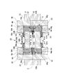
- FIG. 3 is a cross-sectional view showing the configuration of the underwater coupling joint in the first embodiment.
- the coupling joint 50 includes a center tube (second shaft member) 51, a joint member (first shaft member) 52, and a seal portion 60A.
- the joint members 52 are provided at both ends of the center tube 51, respectively.
- the center tube 51 is formed in a cylindrical shape.
- Inner gears 54 are integrally provided at both ends of the center tube 51.
- the inner gear 54 is formed in an annular shape that continues along the outer peripheral surface of the center tube 51.
- the inner gear 54 includes gear teeth (second gear teeth) 54g on the outer periphery thereof.
- the gear tooth 54g has a cross-sectional shape of the tooth surface 54t formed on the outer peripheral portion so that the central portion 54b bulges toward the outer peripheral side with respect to both end portions 54a in the gear width direction along the axis C. Curved in a convex shape.
- the joint member 52 is integrally provided with two disk-shaped joint plates 55 and two cylindrical outer sleeves 56.
- One of the two joint plates 55 is integrally connected to the main shaft 33.
- the other of the two joint plates 55 is integrally connected to the shaft 23.
- the outer sleeves 56 are provided integrally with the joint plate 55, respectively.
- the outer sleeve 56 is provided on the side of the joint plate 55 that faces the center tube 51.
- An inner gear 54 of the center tube 51 is disposed on the inner peripheral side of these outer sleeves 56.
- the outer sleeve 56 has spur gear teeth (first gear teeth) 56g meshing with the gear teeth 54g of the inner gear 54 on the inner peripheral surface thereof.
- the joint member 52 can be relatively displaced in the direction of the axis C with respect to the center tube 51 by meshing the convexly curved gear teeth 54g and the spur gear gears 56g.
- the joint member 52 can be displaced in a direction inclined with respect to the axis C by the meshing of the gear teeth 54g and the gear teeth 56g.
- the impeller 20 having the shaft 23 is allowed to be relatively displaced in the direction of the axis C with respect to the main shaft 33 and to be inclined with respect to each other.
- Joint members 52 are connected to gear teeth 54g at both ends of the center tube 51, respectively. Therefore, the shaft 23 is allowed to be eccentric in the radial direction with respect to the main shaft 33 while the central axis of the other joint member 52 is kept parallel to the central axis of the one joint member 52. .
- Each of the seal portions 60A includes a seal member 61A, an external pressure introduction portion 62A, and a pressure equalizing member (pressure equalizing mechanism) 63A.
- the seal member 61 ⁇ / b> A closes between the outer peripheral surface 51 f of the center tube 51 and the outer sleeve 56 positioned on the outer peripheral side of both end portions of the center tube 51 while maintaining watertightness.
- 61 A of sealing members are formed in the bellows shape which can be expanded-contracted in the axis line C direction. These seal members 61A are made of metal.
- the first end 61a of the seal member 61A is joined to the outer peripheral surface 51f of the center tube 51 by seal welding, friction joining, or the like.
- seal member 61A is joined to the outer sleeve 56 by seal welding, friction joining, or the like.
- seal welding friction joining
- seal members 61A can be deformed following relative displacements in the axial direction, the radial direction, and the tilt direction of the shaft 23 with respect to the main shaft 33 to maintain a sealed state.
- the external pressure introduction part 62A includes a seawater introduction part 64A and a pressure guide hole 65A.
- the seawater introduction part 64A is a cylindrical passage extending along the central axis of the external pressure introduction part 62A.
- the pressure guiding hole 65A is formed so as to penetrate the seawater introducing portion 64A in the thickness direction.
- the outside of the center tube 51 and the seawater introduction part 64A communicate with each other through the pressure introducing hole 65A. Thereby, when the water current generator 10 is submerged in the water, the seawater flows into the seawater introduction part 64A through the pressure guide hole 65A.
- the pressure equalizing member 63A is made of metal and has a bellows shape.
- the pressure equalizing member 63A has a first end 63a closed and a second end 63b opened.
- the pressure equalizing members 63A are disposed at both ends of the seawater introduction portion 64A in the direction of the axis C.
- the second end portions 63b of the pressure equalizing members 63A are fitted so as to close both end portions of the seawater introduction portion 64A.
- the first end 63 a of the pressure equalizing member 63 ⁇ / b> A is a flat surface orthogonal to the central axis of the center tube 51.
- the outer sleeve 56 of the joint member 52 includes two inlets 66 that allow the outer peripheral surface 56a and the inner peripheral surface 56b to communicate with each other.
- a gap formed by the joint plate 55 of the joint member 52, the outer sleeve 56, and the inner gear 54 from the side near the outer peripheral surface 56 a of the outer sleeve 56 through the inlet 66.
- the lubricant J is injected and filled.
- the gap S1 communicates with the space S3 in the seal member 61A through the meshing portion S2 of the gear teeth 54g and the gear teeth 56g.
- the gap S1 communicates with the space S4 in the pressure equalizing member 63A.
- a lubrication space (space) S is constituted by the gap S1, the meshing portion S2, the space S3, and the space S4.
- the lubricant J is filled in the lubrication space S.
- the inlet 66 is closed by attaching a cap (not shown), welding, or the like.
- seawater flows into the seawater introduction portion 64A from the pressure introducing hole 65A. Then, the seawater pressure P1 in the seawater inlet 64A acts on the first end 63a of the pressure equalizing member 63A.
- the pressure equalizing member 63A has a second end 63a that has a second end so that the pressure P1 of seawater acting on the first end 63a and the pressure P2 of the lubricant J in the space S4 in the pressure equalizing member 63A are balanced. It expands and contracts in the direction approaching and separating from the end 63b.
- the bellows-shaped pressure equalizing member 63A has its first end 63a approaching the second end 63b. Shrink to do. Thereby, the pressure P1 of the seawater around the nacelle 30 and the pressure P2 of the lubricant J filled in the lubrication space S are equalized.
- the pressure equalizing member 63A when the coupling joint 50 is submerged in water, the pressure equalizing member 63A is deformed according to the pressure acting from seawater. Therefore, the pressure in the lubrication space S and the external pressure can be equalized. Thereby, it can suppress that a big pressure acts on the sealing member 61A from the outside. For this reason, it is possible to prevent water from entering the lubrication space S filled with the lubricant J from outside or leakage of the lubricant J from the lubrication space S to the outside. As a result, it is possible to maintain the lubrication state in the coupling joint 50 and suppress the burden on maintenance.
- the space can be effectively used.
- the pressure equalizing member 63A in the external pressure introducing portion 62A, the pressure equalizing member 63A is not exposed to the outside, and damage to the pressure equalizing member 63A due to inadvertent contact or the like can be suppressed.
- the pressure equalizing member 63A is made of metal, sufficient strength can be easily ensured. Thereby, damage to pressure equalization member 63A by high pressure P1 of seawater can be controlled. Furthermore, since the pressure equalizing member 63A has a bellows shape, the volume fluctuation amount of the internal space S4 due to the first end 63a approaching and separating from the second end 63b can be increased. Thereby, even when the installation depth of the water current generator 10 is large, the pressure equalizing member 63A can be contracted according to the pressure P1 of the seawater that increases according to the depth of the water. Thereby, equalization with the pressure P2 of the lubricant J can be easily achieved. Therefore, a larger adjustment allowance can be secured as compared with the case of sealing with an O-ring or the like.
- seal member 61A is joined to the outer sleeve 56 and the center tube 51, water enters the lubricating space S filled with the lubricant J from the outside, or the lubricant J leaks out of the lubricating space S to the outside. Can be reduced.
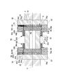
- FIG. 4 is a cross-sectional view showing the configuration of the underwater coupling joint in the second embodiment of the present invention.
- the coupling joint 50 in this embodiment includes a center tube 51, a joint member 52, and a seal portion 60B.
- the seal portion 60B includes a seal member 61A, an external pressure introduction portion 62B, and a pressure equalizing member (pressure equalizing mechanism) 63B.
- the seal member 61 ⁇ / b> A closes the space between the outer peripheral surface 51 f of the center tube 51 and the outer sleeve 56 located on the outer peripheral side of both ends of the center tube 51 while maintaining water tightness.
- the external pressure introduction part 62B has a seawater introduction part 64B and a pressure guide hole 65B.
- the seawater introduction part 64B is formed so as to be continuous in the direction of the axis C across the joint plate 55 on both sides of the coupling joint 50, the main shaft 33 joined to each joint plate 55, and the shaft 23. ing.
- the pressure introducing holes 65B are formed through the main shaft 33 and the shaft 23, respectively. The main shaft 33 and the outside of the shaft 23 communicate with the seawater introduction part 64B through the pressure guide hole 65B.
- the pressure equalizing member 63B is formed in a metal bellows shape.
- the pressure equalizing member 63B is closed on the first end 63a side and opened on the second end 63b side.
- the pressure equalizing member 63B is provided at the end of the seawater introduction part 64B so that the second end 63b faces the gap S1.
- external water acts on the pressure equalizing member 63B by introducing external water into the external pressure introducing portion 62B. Therefore, it is possible to equalize the pressure between the external water and the lubricant J in the lubrication space S. Thereby, it can suppress that a big pressure acts on the sealing member 61A from the outside. For this reason, it is possible to prevent water from entering the lubrication space S filled with the lubricant J from outside or leakage of the lubricant J from the lubrication space S to the outside. As a result, it is possible to maintain the lubrication state in the coupling joint 50 and suppress the burden on maintenance.
- the space can be effectively used. Furthermore, by providing the pressure equalizing member 63B in the external pressure introducing portion 62B, the pressure equalizing member 63B is not exposed to the outside, and damage to the pressure equalizing member 63A due to inadvertent contact or the like can be suppressed.
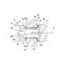
- FIG. 5 is a cross-sectional view showing the configuration of the underwater coupling joint in the third embodiment of the present invention.
- the coupling joint 50 in this embodiment includes a center tube 51, a joint member 52, and a seal portion 60C.
- the seal portion 60C includes a seal member 61A, an external pressure introduction portion 62C, and a pressure equalizing member (pressure equalizing mechanism) 63C.
- the seal member 61 ⁇ / b> A closes the space between the outer peripheral surface 51 f of the center tube 51 and the outer sleeve 56 located on the outer peripheral side of both ends of the center tube 51 while maintaining water tightness.
- the external pressure introducing portion 62C in this embodiment also serves as an injection port 66 formed for injecting the lubricant J into the lubrication space S.
- the inlet 66 is formed in the outer sleeve 56 of the joint member 52.
- the pressure equalizing member 63C is formed in a bellows shape.
- the pressure equalizing member 63C is made of metal.
- the pressure equalizing member 63C is closed on the first end 63a side and opened on the second end 63b side.
- the pressure equalizing member 63 ⁇ / b> C is provided in the injection port 66.
- the pressure equalizing member 63 ⁇ / b> C is provided so that the opened second end 63 b faces the outer peripheral side of the outer sleeve 56.
- the pressure equalizing member 63C also functions as a cap that closes the inlet 66 after the lubricant J is injected.
- the pressure equalizing member 63C when the coupling joint 50 is submerged in water, the pressure equalizing member 63C is deformed in accordance with the seawater pressure P1. Thereby, the pressure of the lubricant J in the lubrication space S and the external pressure are equalized. Therefore, it can suppress that a big pressure acts on the sealing member 61A from the outside. For this reason, it is possible to prevent water from entering the lubrication space S filled with the lubricant J from outside or leakage of the lubricant J from the lubrication space S to the outside. As a result, it is possible to maintain the lubrication state in the coupling joint 50 and suppress the burden on maintenance.
- the pressure equalizing member 63C is provided at the injection port 66 of the lubricant J, it is not necessary to separately provide a site for providing the pressure equalizing member 63C. That is, unlike the configurations shown in the first and second embodiments, it is not necessary to form the pressure guiding holes 65A and 65B and the seawater introducing portions 64A and 64B. Further, the pressure equalizing member 63C also serves as a cap for closing the injection port 66. As a result, the number of parts constituting the seal portion 60C can be reduced, and the possibility of leakage can be further reduced by reducing the places where leakage may occur.
- the seal member 61A has a bellows shape that can be expanded and contracted.
- the seal member 61A may be replaced with another seal member such as an O-ring.
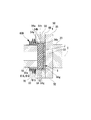
- FIG. 6 is a cross-sectional view showing the configuration of the underwater coupling joint in the fourth embodiment of the present invention.
- the coupling joint 50 in this embodiment includes a center tube 51, a joint member 52, and a seal portion 60D.
- the seal portion 60D includes a seal member 61D.
- the seal member 61D is formed in a bellows shape that can expand and contract in the direction of the axis C. These seal members 61D are made of metal, and block between the outer peripheral surface 51f of the center tube 51 and the outer sleeves 56 positioned on the outer peripheral sides of both ends of the center tube 51 while maintaining water tightness.
- the seal member 61D is formed in a tapered shape whose outer diameter gradually increases as the outer sleeve 56 is approached.
- the seawater pressure P ⁇ b> 1 also acts in the axial direction of the center tube 51.
- the seal member 61D also serves as a pressure equalizing member (pressure equalizing mechanism) 63D. That is, when the nacelle 30 of the water current generator 10 is submerged in water, the seal member 61D is slightly pressed in the axial direction by the pressure P1 of seawater acting on the seal member 61D. Shrinks in a direction approaching the end 61b. Thereby, the pressure P1 of the seawater around the nacelle 30 and the pressure P2 of the lubricant J in the lubricating space S5 in the seal member 61D are equalized.
- pressure equalizing member pressure equalizing mechanism
- the seal member 61D can be deformed according to the external pressure, and also serves as the pressure equalizing member 63D.
- the seal member 61D can be deformed according to the external pressure, and also serves as the pressure equalizing member 63D.
- it is not necessary to form the pressure introducing holes 65A and 65B and the seawater introducing portions 64A and 64B or to provide the pressure equalizing members 63A to 63C. .
- the number of parts constituting the seal portion 60D can be reduced.
- the possibility of leakage can be further reduced by reducing the number of places where leakage can occur.
- the seal member 61D when the coupling joint 50 is submerged in the water, the seal member 61D is deformed according to the seawater pressure P1. Therefore, the pressure P2 of the lubricant J in the lubrication space S and the external pressure P1 can be equalized. Thereby, it can suppress that a big pressure acts on seal member 61D from the outside. As a result, it is possible to prevent water from entering the lubrication space S filled with the lubricant J from outside or leakage of the lubricant J from the lubrication space S to the outside.
- the seal member 61D has a bellows shape, but is not limited thereto. Any configuration may be used as long as the volume inside the seal member 61D changes according to the pressure P1 of the seawater. For example, as shown in FIG. 7, the outer diameter of the bellows-like seal member 61D is gradually increased in the direction in which the seawater pressure P1 acts, and a pressure receiving surface 70 that receives the seawater pressure P1 is provided. May be. With this configuration, the expansion and contraction of the seal member 61D by the seawater pressure P1 can be efficiently performed. As described above, the configuration in which the outer diameter is gradually increased can be similarly applied to the pressure equalizing members 63A to 63C.
- the present invention is not limited to the above-described embodiment, and includes various modifications made to the above-described embodiment without departing from the spirit of the present invention. That is, the specific shapes, configurations, and the like given in the embodiment are merely examples, and can be changed as appropriate.
- the bellows-like seal member 61A and the pressure equalizing members 63A to 63C are used.
- the outer diameters of the bellows-shaped seal member 61A and the pressure equalizing members 63A to 63C may be gradually increased in the direction in which the seawater pressure P1 acts.
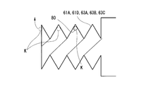
- the seal members 61A and 61D and the pressure equalizing members 63A to 63C may have a bellows shape, and the groove 80 formed on the inner peripheral surface thereof may be formed in a spiral shape.
- the bubbles K remaining in the groove 80 when the lubricant J is injected can be easily obtained by rotating the seal members 61A and 61D and the pressure equalizing members 63A to 63C around the respective central axes. Can be discharged.
- the seal members 61A and 61D and the pressure equalizing members 63A to 63C are rotated so that the bubble K moves along the groove 80 toward the injection port 66.
- the bubbles K discharged from the seal members 61A and 61D and the pressure equalizing members 63A to 63C can be guided to the injection port 66 and discharged to the outside from the injection port 66 (see FIG. 3). If bubbles K remain, even if the pressure equalizing members 63A to 63C and the seal member 61D are contracted by the seawater pressure P1, bubbles having a lower density than the lubricant J are crushed, so the pressure P2 of the lubricant J is efficient. Does not rise well. However, by discharging the bubbles K as described above, it is possible to efficiently equalize the seawater pressure P1 and the lubricant J pressure P2.
- seal members 61A and 61D having the spiral groove 80 may be mounted on the outer sleeve 56 having a tapered inner peripheral surface 56c as shown in FIG. By doing in this way, the bubble which escaped from sealing member 61A, 61D can be smoothly passed through the meshing part S2, and can be moved to the injection port 66 side. Therefore, the remaining of the bubbles K can be further reduced.
- the water current generator 10 was installed in the deep sea was demonstrated, it is not restricted to the deep sea.
- the number of blades 22 of the impeller 20 is not limited to the number described above as long as it is a plurality. In addition to this, for example, other configurations can be appropriately employed for the configuration of each part of the water current generator 10.
- This invention can be applied to an underwater coupling joint and a water current generator.
- the underwater coupling joint and the water current generator to which the present invention is applied can maintain a lubrication state in the underwater coupling joint and can suppress a burden on maintenance.
Landscapes
- Engineering & Computer Science (AREA)
- General Engineering & Computer Science (AREA)
- Mechanical Engineering (AREA)
- Chemical & Material Sciences (AREA)
- Combustion & Propulsion (AREA)
- Power Engineering (AREA)
- Other Liquid Machine Or Engine Such As Wave Power Use (AREA)
- Sealing Devices (AREA)
- Diaphragms And Bellows (AREA)
Priority Applications (2)
| Application Number | Priority Date | Filing Date | Title |
|---|---|---|---|
| US15/551,104 US20180031046A1 (en) | 2015-02-17 | 2015-10-23 | Underwater coupling joint, and water flow power generator |
| CN201580076203.1A CN107250587B (zh) | 2015-02-17 | 2015-10-23 | 水中连接接头、水流发电机 |
Applications Claiming Priority (2)
| Application Number | Priority Date | Filing Date | Title |
|---|---|---|---|
| JP2015028495A JP6244609B2 (ja) | 2015-02-17 | 2015-02-17 | 水中カップリング継手、水流発電機 |
| JP2015-028495 | 2015-02-17 |
Publications (1)
| Publication Number | Publication Date |
|---|---|
| WO2016132601A1 true WO2016132601A1 (ja) | 2016-08-25 |
Family
ID=56688899
Family Applications (1)
| Application Number | Title | Priority Date | Filing Date |
|---|---|---|---|
| PCT/JP2015/079959 Ceased WO2016132601A1 (ja) | 2015-02-17 | 2015-10-23 | 水中カップリング継手、水流発電機 |
Country Status (4)
| Country | Link |
|---|---|
| US (1) | US20180031046A1 (enExample) |
| JP (1) | JP6244609B2 (enExample) |
| CN (1) | CN107250587B (enExample) |
| WO (1) | WO2016132601A1 (enExample) |
Families Citing this family (2)
| Publication number | Priority date | Publication date | Assignee | Title |
|---|---|---|---|---|
| IT201800020029A1 (it) * | 2018-12-18 | 2019-03-18 | Green Gear Trasmissioni S R L | Elemento di allungamento a ingranaggi con lubrificazione automatica |
| CN111043175B (zh) * | 2019-11-25 | 2021-01-19 | 北京汽车股份有限公司 | 护套组、驱动半轴总成和车辆 |
Citations (5)
| Publication number | Priority date | Publication date | Assignee | Title |
|---|---|---|---|---|
| JP2005331018A (ja) * | 2004-05-19 | 2005-12-02 | Nissan Motor Co Ltd | プロペラシャフト用等速ジョイント装置 |
| JP2006144965A (ja) * | 2004-11-22 | 2006-06-08 | Heishin Engineering & Equipment Co Ltd | 偏心軸継手構造とその偏心軸継手構造を備えた一軸偏心ねじポンプ |
| JP2007239878A (ja) * | 2006-03-08 | 2007-09-20 | Ntn Corp | ドライブシャフト用ブーツ |
| JP2008099373A (ja) * | 2006-10-06 | 2008-04-24 | Furukawa Co Ltd | 水力発電システム |
| JP2011021619A (ja) * | 2009-07-13 | 2011-02-03 | Seisa Gear Ltd | ギヤカップリング |
Family Cites Families (5)
| Publication number | Priority date | Publication date | Assignee | Title |
|---|---|---|---|---|
| DE10152712B4 (de) * | 2001-10-19 | 2015-10-15 | Aloys Wobben | Generator für ein Wasserkraftwerk |
| US8310079B2 (en) * | 2008-07-14 | 2012-11-13 | William Kingston | Tidal energy system |
| US9193452B2 (en) * | 2012-12-14 | 2015-11-24 | Raymond George Carreker | Direct orientation vector rotor |
| US20140370995A1 (en) * | 2012-12-26 | 2014-12-18 | Ge Oil & Gas Esp, Inc. | Flexible joint connection |
| US9976602B2 (en) * | 2016-02-23 | 2018-05-22 | Summit Esp, Llc | Torque transmitting coupling for an electrical submersible pump equipment string |
-
2015
- 2015-02-17 JP JP2015028495A patent/JP6244609B2/ja not_active Expired - Fee Related
- 2015-10-23 WO PCT/JP2015/079959 patent/WO2016132601A1/ja not_active Ceased
- 2015-10-23 CN CN201580076203.1A patent/CN107250587B/zh not_active Expired - Fee Related
- 2015-10-23 US US15/551,104 patent/US20180031046A1/en not_active Abandoned
Patent Citations (5)
| Publication number | Priority date | Publication date | Assignee | Title |
|---|---|---|---|---|
| JP2005331018A (ja) * | 2004-05-19 | 2005-12-02 | Nissan Motor Co Ltd | プロペラシャフト用等速ジョイント装置 |
| JP2006144965A (ja) * | 2004-11-22 | 2006-06-08 | Heishin Engineering & Equipment Co Ltd | 偏心軸継手構造とその偏心軸継手構造を備えた一軸偏心ねじポンプ |
| JP2007239878A (ja) * | 2006-03-08 | 2007-09-20 | Ntn Corp | ドライブシャフト用ブーツ |
| JP2008099373A (ja) * | 2006-10-06 | 2008-04-24 | Furukawa Co Ltd | 水力発電システム |
| JP2011021619A (ja) * | 2009-07-13 | 2011-02-03 | Seisa Gear Ltd | ギヤカップリング |
Also Published As
| Publication number | Publication date |
|---|---|
| US20180031046A1 (en) | 2018-02-01 |
| CN107250587B (zh) | 2019-11-26 |
| JP2016151307A (ja) | 2016-08-22 |
| CN107250587A (zh) | 2017-10-13 |
| JP6244609B2 (ja) | 2017-12-13 |
Similar Documents
| Publication | Publication Date | Title |
|---|---|---|
| US10648569B2 (en) | Sliding component | |
| US10663054B2 (en) | Oil transfer unit for transferring oil between a stationary part and a rotating part | |
| US10458535B2 (en) | Oil transfer unit for transferring oil between a stationary part and a rotating part | |
| JPWO2012029129A1 (ja) | 遊星歯車機構、風力発電装置、及び遊星歯車機構のキャリアの製造方法 | |
| KR20120054559A (ko) | 유성 기어 기구, 베어링 구조, 풍력 발전 장치 및 유성 기어의 제조 방법 | |
| CA2927748C (en) | Down hole harmonic drive transmission | |
| CN102401137A (zh) | 主动式密封排出装置 | |
| JP6244609B2 (ja) | 水中カップリング継手、水流発電機 | |
| US4810105A (en) | Bearing sleeves | |
| US10753456B2 (en) | Oil transfer unit for transferring oil between a stationary part and a rotating part | |
| CN210830401U (zh) | 一种风电齿轮箱输出轴回油结构 | |
| JP2006234036A (ja) | 液体潤滑フォイル式動圧軸受 | |
| US10731623B2 (en) | Water-flow power generating apparatus | |
| US20190101024A1 (en) | Assembly provided with a rotating supporting member and with an oil transfer unit for transferring oil to such rotating supporting member | |
| KR101617028B1 (ko) | 선박용 추진장치 및 이를 갖춘 선박 | |
| CN210290239U (zh) | 一种水下轴承 | |
| Steele | Propulsion Machinery Considerations for Contrarotating Propeller Systems |
Legal Events
| Date | Code | Title | Description |
|---|---|---|---|
| 121 | Ep: the epo has been informed by wipo that ep was designated in this application |
Ref document number: 15882702 Country of ref document: EP Kind code of ref document: A1 |
|
| NENP | Non-entry into the national phase |
Ref country code: DE |
|
| 122 | Ep: pct application non-entry in european phase |
Ref document number: 15882702 Country of ref document: EP Kind code of ref document: A1 |