WO2016132601A1 - 水中カップリング継手、水流発電機 - Google Patents
水中カップリング継手、水流発電機 Download PDFInfo
- Publication number
- WO2016132601A1 WO2016132601A1 PCT/JP2015/079959 JP2015079959W WO2016132601A1 WO 2016132601 A1 WO2016132601 A1 WO 2016132601A1 JP 2015079959 W JP2015079959 W JP 2015079959W WO 2016132601 A1 WO2016132601 A1 WO 2016132601A1
- Authority
- WO
- WIPO (PCT)
- Prior art keywords
- pressure
- coupling joint
- gear teeth
- space
- lubricant
- Prior art date
- Legal status (The legal status is an assumption and is not a legal conclusion. Google has not performed a legal analysis and makes no representation as to the accuracy of the status listed.)
- Ceased
Links
Images




Classifications
-
- F—MECHANICAL ENGINEERING; LIGHTING; HEATING; WEAPONS; BLASTING
- F16—ENGINEERING ELEMENTS AND UNITS; GENERAL MEASURES FOR PRODUCING AND MAINTAINING EFFECTIVE FUNCTIONING OF MACHINES OR INSTALLATIONS; THERMAL INSULATION IN GENERAL
- F16D—COUPLINGS FOR TRANSMITTING ROTATION; CLUTCHES; BRAKES
- F16D3/00—Yielding couplings, i.e. with means permitting movement between the connected parts during the drive
- F16D3/16—Universal joints in which flexibility is produced by means of pivots or sliding or rolling connecting parts
- F16D3/18—Universal joints in which flexibility is produced by means of pivots or sliding or rolling connecting parts the coupling parts (1) having slidably-interengaging teeth
-
- F—MECHANICAL ENGINEERING; LIGHTING; HEATING; WEAPONS; BLASTING
- F03—MACHINES OR ENGINES FOR LIQUIDS; WIND, SPRING, OR WEIGHT MOTORS; PRODUCING MECHANICAL POWER OR A REACTIVE PROPULSIVE THRUST, NOT OTHERWISE PROVIDED FOR
- F03B—MACHINES OR ENGINES FOR LIQUIDS
- F03B11/00—Parts or details not provided for in, or of interest apart from, the preceding groups, e.g. wear-protection couplings, between turbine and generator
- F03B11/006—Sealing arrangements
-
- F—MECHANICAL ENGINEERING; LIGHTING; HEATING; WEAPONS; BLASTING
- F03—MACHINES OR ENGINES FOR LIQUIDS; WIND, SPRING, OR WEIGHT MOTORS; PRODUCING MECHANICAL POWER OR A REACTIVE PROPULSIVE THRUST, NOT OTHERWISE PROVIDED FOR
- F03B—MACHINES OR ENGINES FOR LIQUIDS
- F03B13/00—Adaptations of machines or engines for special use; Combinations of machines or engines with driving or driven apparatus; Power stations or aggregates
- F03B13/10—Submerged units incorporating electric generators or motors
-
- F—MECHANICAL ENGINEERING; LIGHTING; HEATING; WEAPONS; BLASTING
- F03—MACHINES OR ENGINES FOR LIQUIDS; WIND, SPRING, OR WEIGHT MOTORS; PRODUCING MECHANICAL POWER OR A REACTIVE PROPULSIVE THRUST, NOT OTHERWISE PROVIDED FOR
- F03B—MACHINES OR ENGINES FOR LIQUIDS
- F03B17/00—Other machines or engines
- F03B17/06—Other machines or engines using liquid flow with predominantly kinetic energy conversion, e.g. of swinging-flap type, "run-of-river", "ultra-low head"
- F03B17/061—Other machines or engines using liquid flow with predominantly kinetic energy conversion, e.g. of swinging-flap type, "run-of-river", "ultra-low head" with rotation axis substantially in flow direction
-
- F—MECHANICAL ENGINEERING; LIGHTING; HEATING; WEAPONS; BLASTING
- F16—ENGINEERING ELEMENTS AND UNITS; GENERAL MEASURES FOR PRODUCING AND MAINTAINING EFFECTIVE FUNCTIONING OF MACHINES OR INSTALLATIONS; THERMAL INSULATION IN GENERAL
- F16D—COUPLINGS FOR TRANSMITTING ROTATION; CLUTCHES; BRAKES
- F16D3/00—Yielding couplings, i.e. with means permitting movement between the connected parts during the drive
- F16D3/16—Universal joints in which flexibility is produced by means of pivots or sliding or rolling connecting parts
- F16D3/18—Universal joints in which flexibility is produced by means of pivots or sliding or rolling connecting parts the coupling parts (1) having slidably-interengaging teeth
- F16D3/185—Universal joints in which flexibility is produced by means of pivots or sliding or rolling connecting parts the coupling parts (1) having slidably-interengaging teeth radial teeth connecting concentric inner and outer coupling parts
-
- F—MECHANICAL ENGINEERING; LIGHTING; HEATING; WEAPONS; BLASTING
- F16—ENGINEERING ELEMENTS AND UNITS; GENERAL MEASURES FOR PRODUCING AND MAINTAINING EFFECTIVE FUNCTIONING OF MACHINES OR INSTALLATIONS; THERMAL INSULATION IN GENERAL
- F16D—COUPLINGS FOR TRANSMITTING ROTATION; CLUTCHES; BRAKES
- F16D3/00—Yielding couplings, i.e. with means permitting movement between the connected parts during the drive
- F16D3/84—Shrouds, e.g. casings, covers; Sealing means specially adapted therefor
- F16D3/841—Open covers, e.g. guards for agricultural p.t.o. shafts
-
- F—MECHANICAL ENGINEERING; LIGHTING; HEATING; WEAPONS; BLASTING
- F16—ENGINEERING ELEMENTS AND UNITS; GENERAL MEASURES FOR PRODUCING AND MAINTAINING EFFECTIVE FUNCTIONING OF MACHINES OR INSTALLATIONS; THERMAL INSULATION IN GENERAL
- F16D—COUPLINGS FOR TRANSMITTING ROTATION; CLUTCHES; BRAKES
- F16D3/00—Yielding couplings, i.e. with means permitting movement between the connected parts during the drive
- F16D3/84—Shrouds, e.g. casings, covers; Sealing means specially adapted therefor
- F16D3/843—Shrouds, e.g. casings, covers; Sealing means specially adapted therefor enclosed covers
- F16D3/845—Shrouds, e.g. casings, covers; Sealing means specially adapted therefor enclosed covers allowing relative movement of joint parts due to the flexing of the cover
-
- F—MECHANICAL ENGINEERING; LIGHTING; HEATING; WEAPONS; BLASTING
- F16—ENGINEERING ELEMENTS AND UNITS; GENERAL MEASURES FOR PRODUCING AND MAINTAINING EFFECTIVE FUNCTIONING OF MACHINES OR INSTALLATIONS; THERMAL INSULATION IN GENERAL
- F16J—PISTONS; CYLINDERS; SEALINGS
- F16J15/00—Sealings
- F16J15/50—Sealings between relatively-movable members, by means of a sealing without relatively-moving surfaces, e.g. fluid-tight sealings for transmitting motion through a wall
- F16J15/52—Sealings between relatively-movable members, by means of a sealing without relatively-moving surfaces, e.g. fluid-tight sealings for transmitting motion through a wall by means of sealing bellows or diaphragms
-
- F—MECHANICAL ENGINEERING; LIGHTING; HEATING; WEAPONS; BLASTING
- F16—ENGINEERING ELEMENTS AND UNITS; GENERAL MEASURES FOR PRODUCING AND MAINTAINING EFFECTIVE FUNCTIONING OF MACHINES OR INSTALLATIONS; THERMAL INSULATION IN GENERAL
- F16J—PISTONS; CYLINDERS; SEALINGS
- F16J3/00—Diaphragms; Bellows; Bellows pistons
- F16J3/04—Bellows
-
- F—MECHANICAL ENGINEERING; LIGHTING; HEATING; WEAPONS; BLASTING
- F05—INDEXING SCHEMES RELATING TO ENGINES OR PUMPS IN VARIOUS SUBCLASSES OF CLASSES F01-F04
- F05B—INDEXING SCHEME RELATING TO WIND, SPRING, WEIGHT, INERTIA OR LIKE MOTORS, TO MACHINES OR ENGINES FOR LIQUIDS COVERED BY SUBCLASSES F03B, F03D AND F03G
- F05B2240/00—Components
- F05B2240/50—Bearings
-
- F—MECHANICAL ENGINEERING; LIGHTING; HEATING; WEAPONS; BLASTING
- F05—INDEXING SCHEMES RELATING TO ENGINES OR PUMPS IN VARIOUS SUBCLASSES OF CLASSES F01-F04
- F05B—INDEXING SCHEME RELATING TO WIND, SPRING, WEIGHT, INERTIA OR LIKE MOTORS, TO MACHINES OR ENGINES FOR LIQUIDS COVERED BY SUBCLASSES F03B, F03D AND F03G
- F05B2260/00—Function
- F05B2260/40—Transmission of power
- F05B2260/403—Transmission of power through the shape of the drive components
- F05B2260/4031—Transmission of power through the shape of the drive components as in toothed gearing
-
- F—MECHANICAL ENGINEERING; LIGHTING; HEATING; WEAPONS; BLASTING
- F05—INDEXING SCHEMES RELATING TO ENGINES OR PUMPS IN VARIOUS SUBCLASSES OF CLASSES F01-F04
- F05B—INDEXING SCHEME RELATING TO WIND, SPRING, WEIGHT, INERTIA OR LIKE MOTORS, TO MACHINES OR ENGINES FOR LIQUIDS COVERED BY SUBCLASSES F03B, F03D AND F03G
- F05B2260/00—Function
- F05B2260/98—Lubrication
-
- F—MECHANICAL ENGINEERING; LIGHTING; HEATING; WEAPONS; BLASTING
- F16—ENGINEERING ELEMENTS AND UNITS; GENERAL MEASURES FOR PRODUCING AND MAINTAINING EFFECTIVE FUNCTIONING OF MACHINES OR INSTALLATIONS; THERMAL INSULATION IN GENERAL
- F16D—COUPLINGS FOR TRANSMITTING ROTATION; CLUTCHES; BRAKES
- F16D2300/00—Special features for couplings or clutches
- F16D2300/06—Lubrication details not provided for in group F16D13/74
-
- Y—GENERAL TAGGING OF NEW TECHNOLOGICAL DEVELOPMENTS; GENERAL TAGGING OF CROSS-SECTIONAL TECHNOLOGIES SPANNING OVER SEVERAL SECTIONS OF THE IPC; TECHNICAL SUBJECTS COVERED BY FORMER USPC CROSS-REFERENCE ART COLLECTIONS [XRACs] AND DIGESTS
- Y02—TECHNOLOGIES OR APPLICATIONS FOR MITIGATION OR ADAPTATION AGAINST CLIMATE CHANGE
- Y02E—REDUCTION OF GREENHOUSE GAS [GHG] EMISSIONS, RELATED TO ENERGY GENERATION, TRANSMISSION OR DISTRIBUTION
- Y02E10/00—Energy generation through renewable energy sources
- Y02E10/20—Hydro energy
-
- Y—GENERAL TAGGING OF NEW TECHNOLOGICAL DEVELOPMENTS; GENERAL TAGGING OF CROSS-SECTIONAL TECHNOLOGIES SPANNING OVER SEVERAL SECTIONS OF THE IPC; TECHNICAL SUBJECTS COVERED BY FORMER USPC CROSS-REFERENCE ART COLLECTIONS [XRACs] AND DIGESTS
- Y02—TECHNOLOGIES OR APPLICATIONS FOR MITIGATION OR ADAPTATION AGAINST CLIMATE CHANGE
- Y02E—REDUCTION OF GREENHOUSE GAS [GHG] EMISSIONS, RELATED TO ENERGY GENERATION, TRANSMISSION OR DISTRIBUTION
- Y02E10/00—Energy generation through renewable energy sources
- Y02E10/30—Energy from the sea, e.g. using wave energy or salinity gradient
Definitions
- the present invention relates to an underwater coupling joint and a water current generator. This application claims priority based on Japanese Patent Application No. 2015-028495 for which it applied to Japan on February 17, 2015, and uses the content here.
- a coupling device as described in Patent Document 1 may be used between the impeller and the rotating shaft of the generator.
- Such a coupling device allows relative displacement in the axial direction, radial direction and tilt direction between the side close to the impeller and the side close to the generator, and between the impeller and the rotating shaft of the generator. Transmits rotational force.
- a lubricant is required at the meshing portion of the gear to suppress wear.
- the coupling device described in Patent Document 1 includes a seal member in order to prevent a fluid having a high pressure from the outside from entering.
- An object of the present invention is to provide an underwater coupling joint and a water current generator capable of suppressing a burden on maintenance.
- the underwater coupling joint includes the first shaft member having the first gear teeth.
- the underwater coupling joint has second gear teeth that mesh with the first gear teeth, and transmits rotational force between the first gear teeth and the first shaft member via the second gear teeth.
- a second shaft member is further provided.
- the underwater coupling joint includes a seal member for closing the space including the meshing portion of the first gear tooth and the second gear tooth from the outside between the first shaft member and the second shaft member.
- the underwater coupling joint further includes a lubricant filled in the space.
- An underwater coupling joint is provided facing a part of the space, and deforms according to the external pressure to change the volume of the space, thereby reducing the pressure of the lubricant and the external pressure.
- a pressure equalizing mechanism for equalizing is further provided.
- the pressure equalizing mechanism when the underwater coupling joint is submerged in water, the pressure equalizing mechanism can be deformed according to the pressure outside the underwater coupling device, that is, the ambient pressure. Due to the deformation of the pressure equalizing mechanism, the volume of the space filled with the lubricant can be changed to equalize the pressure of the lubricant in the space and the external pressure. Thereby, it can suppress that a big differential pressure arises between each of a sealing member and a 1st shaft member and a 2nd shaft member. As a result, it is possible to prevent water from entering the space filled with the lubricant from outside or leakage of the lubricant from the space to the outside.
- the underwater coupling joint is configured such that the pressure equalizing mechanism in the first aspect has a cylindrical shape with the first end opened and the other end closed, and the first end and the other It may be a bellows that can be expanded and contracted in a direction in which the end contacts and separates.
- the bellows can be shortened in the direction in which the other end approaches the opened first end portion.
- the bellows can be extended in a direction in which the other end side is separated from the first end portion. Thereby, the volume of space changes and equalization of each pressure of external water and the lubricant in space can be aimed at.
- the bellows in the second aspect may have a spiral groove on the inner peripheral surface.
- the underwater coupling joint according to any one of the first to third aspects, the one of the first shaft member and the second shaft member, An external pressure introduction part into which an external pressure is introduced may be provided. Furthermore, the pressure equalizing mechanism may be provided in the external pressure introducing portion. By comprising in this way, an external pressure can be made to act on a pressure equalization mechanism via an external pressure introduction part. Therefore, it is possible to equalize the pressure between the external water and the lubricant in the space. By providing the external pressure introducing portion inside one of the first shaft member and the second shaft member, the space can be effectively used. Furthermore, since the pressure equalizing mechanism is not exposed to the outside by providing the pressure equalizing mechanism at the external pressure introducing portion, it is possible to prevent the pressure equalizing mechanism from being damaged due to careless contact or the like.
- the space is provided in one of the first shaft member and the second shaft member in the space.
- An inlet for injecting the lubricant from the outside may be provided.
- the pressure equalizing mechanism may be provided at the inlet.
- the seal member in the submerged coupling joint according to any one of the first to third aspects, is formed to be deformable in accordance with the external pressure, and the pressure equalization You may make it serve as a mechanism.
- the number of parts can be suppressed because the seal member also serves as a pressure equalizing mechanism.
- the seal member in the underwater coupling joint according to any one of the first to sixth aspects, is joined to the first shaft member and the second shaft member. You may be allowed to. As described above, by joining the seal member to the first shaft member and the second shaft member, water enters the space filled with the lubricant, or the lubricant leaks from the space to the outside. Can be suppressed.
- a water current generator includes an impeller having a plurality of blades, a generator driven by the impeller, a rotating shaft of the impeller, and an input shaft of the generator. And an underwater coupling joint as described above. By comprising in this way, in an underwater coupling joint, it can suppress that water permeates into the space filled with the lubricant from the outside, or the lubricant leaks out of the space from the outside.
- the lubrication state of the underwater coupling joint can be maintained and the burden on maintenance can be suppressed.
- FIG. 1 is a perspective view showing a water current generator of this embodiment.
- FIG. 2 is a cross-sectional view illustrating a configuration of a connection portion between the impeller and the nacelle in the embodiment of the water current generator.
- the water current generator 10 in this embodiment is installed in seawater having a large depth by being moored to a seabed or an underwater structure via a mooring line (not shown).
- the water current generator 10 includes an impeller 20 and a nacelle 30.
- the impeller 20 includes a hub 21 and a blade 22.
- the hub 21 is disposed at the center of the impeller 20.
- the hub 21 is formed in a so-called bullet shape whose outer diameter gradually decreases toward the tip 21a.
- the hub 21 has an end surface 21b on the side opposite to the tip 21a.
- the end surface 21b is orthogonal to the rotation center axis C of the impeller 20 (hereinafter simply referred to as the axis C).
- a cylindrical portion 21 c is integrally provided on the outer peripheral portion of the end surface 21 b of the hub 21.
- the cylindrical portion 21c is formed in a cylindrical shape extending in the direction in which the axis C extends (hereinafter simply referred to as the axis C direction) toward the side opposite to the tip 21a.
- a shaft (rotary shaft) 23 is integrally attached to the end surface 21 b of the hub 21. The shaft 23 protrudes in the direction of the axis C toward the side opposite to the tip 21a.
- a plurality of blades 22 are provided on the outer peripheral portion of the hub 21 at intervals in the circumferential direction.
- two blades 22 are provided. These two blades 22 are arranged at rotationally symmetric positions.
- Each blade 22 has a base end portion 22 a fixed integrally to the cylindrical portion 21 c of the hub 21.
- Each blade 22 extends radially outward from the hub 21 toward its tip 22b.
- the nacelle 30 includes a casing 31, a generator 32, and a main shaft 33.
- the casing 31 is formed in a cylindrical shape extending in the axis C direction.
- the casing 31 is provided with an impeller support portion 34 at a first end portion 31a thereof.
- the impeller support part 34 supports the impeller 20 rotatably.
- a pair of external bearings 35 are provided on the outer peripheral surface of the impeller support portion 34 with an interval in the direction of the axis C.
- the impeller 20 is rotatably supported by the impeller support portion 34 via these external bearings 35.
- Each external bearing 35 is formed of resin, for example, and functions as a so-called sliding bearing that rotatably supports the impeller 20 using surrounding seawater as a lubricant.
- a partition wall 36 is provided in the casing 31.
- the partition wall 36 has a plane that is orthogonal to the axis C and faces away from the first end portion 31a in the direction of the axis C (hereinafter simply referred to as the second end portion side).
- a sealed generator chamber 37 is formed in the casing 31 on the second end side of the partition wall 36 in the axis C direction.
- the generator chamber 37 has an air atmosphere.
- a generator 32 is accommodated in the generator chamber 37.
- the generator 32 includes an input shaft 32a.
- the input shaft 32a protrudes along the axis C toward the side close to the partition wall 36.
- the generator 32 includes a rotor (not shown) provided integrally with the input shaft 32a, and a stator (not shown) facing the rotor.
- the generator 32 generates power by rotating the rotor together with the input shaft 32a relative to the stator.
- the electric power generated by the generator 32 is supplied to the outside through a transmission line (not shown).
- the main shaft 33 is connected to the input shaft 32a of the generator 32 through a speed increaser (not shown), a brake (not shown), and the like.
- the main shaft 33 extends into the impeller support portion 34 through a shaft hole 36 h formed in the partition wall 36.
- a ring-shaped seal member 38 is provided between the main shaft 33 and the shaft hole 36h. The seal member 38 prevents water from entering the generator chamber 37 from around the main shaft 33.
- a coupling joint (underwater coupling joint) 50 is provided between the main shaft 33 and the shaft 23 provided on the hub 21 of the impeller 20.
- the main shaft 33 and the shaft 23 are connected via the coupling joint 50.
- FIG. 3 is a cross-sectional view showing the configuration of the underwater coupling joint in the first embodiment.
- the coupling joint 50 includes a center tube (second shaft member) 51, a joint member (first shaft member) 52, and a seal portion 60A.
- the joint members 52 are provided at both ends of the center tube 51, respectively.
- the center tube 51 is formed in a cylindrical shape.
- Inner gears 54 are integrally provided at both ends of the center tube 51.
- the inner gear 54 is formed in an annular shape that continues along the outer peripheral surface of the center tube 51.
- the inner gear 54 includes gear teeth (second gear teeth) 54g on the outer periphery thereof.
- the gear tooth 54g has a cross-sectional shape of the tooth surface 54t formed on the outer peripheral portion so that the central portion 54b bulges toward the outer peripheral side with respect to both end portions 54a in the gear width direction along the axis C. Curved in a convex shape.
- the joint member 52 is integrally provided with two disk-shaped joint plates 55 and two cylindrical outer sleeves 56.
- One of the two joint plates 55 is integrally connected to the main shaft 33.
- the other of the two joint plates 55 is integrally connected to the shaft 23.
- the outer sleeves 56 are provided integrally with the joint plate 55, respectively.
- the outer sleeve 56 is provided on the side of the joint plate 55 that faces the center tube 51.
- An inner gear 54 of the center tube 51 is disposed on the inner peripheral side of these outer sleeves 56.
- the outer sleeve 56 has spur gear teeth (first gear teeth) 56g meshing with the gear teeth 54g of the inner gear 54 on the inner peripheral surface thereof.
- the joint member 52 can be relatively displaced in the direction of the axis C with respect to the center tube 51 by meshing the convexly curved gear teeth 54g and the spur gear gears 56g.
- the joint member 52 can be displaced in a direction inclined with respect to the axis C by the meshing of the gear teeth 54g and the gear teeth 56g.
- the impeller 20 having the shaft 23 is allowed to be relatively displaced in the direction of the axis C with respect to the main shaft 33 and to be inclined with respect to each other.
- Joint members 52 are connected to gear teeth 54g at both ends of the center tube 51, respectively. Therefore, the shaft 23 is allowed to be eccentric in the radial direction with respect to the main shaft 33 while the central axis of the other joint member 52 is kept parallel to the central axis of the one joint member 52. .
- Each of the seal portions 60A includes a seal member 61A, an external pressure introduction portion 62A, and a pressure equalizing member (pressure equalizing mechanism) 63A.
- the seal member 61 ⁇ / b> A closes between the outer peripheral surface 51 f of the center tube 51 and the outer sleeve 56 positioned on the outer peripheral side of both end portions of the center tube 51 while maintaining watertightness.
- 61 A of sealing members are formed in the bellows shape which can be expanded-contracted in the axis line C direction. These seal members 61A are made of metal.
- the first end 61a of the seal member 61A is joined to the outer peripheral surface 51f of the center tube 51 by seal welding, friction joining, or the like.
- seal member 61A is joined to the outer sleeve 56 by seal welding, friction joining, or the like.
- seal welding friction joining
- seal members 61A can be deformed following relative displacements in the axial direction, the radial direction, and the tilt direction of the shaft 23 with respect to the main shaft 33 to maintain a sealed state.
- the external pressure introduction part 62A includes a seawater introduction part 64A and a pressure guide hole 65A.
- the seawater introduction part 64A is a cylindrical passage extending along the central axis of the external pressure introduction part 62A.
- the pressure guiding hole 65A is formed so as to penetrate the seawater introducing portion 64A in the thickness direction.
- the outside of the center tube 51 and the seawater introduction part 64A communicate with each other through the pressure introducing hole 65A. Thereby, when the water current generator 10 is submerged in the water, the seawater flows into the seawater introduction part 64A through the pressure guide hole 65A.
- the pressure equalizing member 63A is made of metal and has a bellows shape.
- the pressure equalizing member 63A has a first end 63a closed and a second end 63b opened.
- the pressure equalizing members 63A are disposed at both ends of the seawater introduction portion 64A in the direction of the axis C.
- the second end portions 63b of the pressure equalizing members 63A are fitted so as to close both end portions of the seawater introduction portion 64A.
- the first end 63 a of the pressure equalizing member 63 ⁇ / b> A is a flat surface orthogonal to the central axis of the center tube 51.
- the outer sleeve 56 of the joint member 52 includes two inlets 66 that allow the outer peripheral surface 56a and the inner peripheral surface 56b to communicate with each other.
- a gap formed by the joint plate 55 of the joint member 52, the outer sleeve 56, and the inner gear 54 from the side near the outer peripheral surface 56 a of the outer sleeve 56 through the inlet 66.
- the lubricant J is injected and filled.
- the gap S1 communicates with the space S3 in the seal member 61A through the meshing portion S2 of the gear teeth 54g and the gear teeth 56g.
- the gap S1 communicates with the space S4 in the pressure equalizing member 63A.
- a lubrication space (space) S is constituted by the gap S1, the meshing portion S2, the space S3, and the space S4.
- the lubricant J is filled in the lubrication space S.
- the inlet 66 is closed by attaching a cap (not shown), welding, or the like.
- seawater flows into the seawater introduction portion 64A from the pressure introducing hole 65A. Then, the seawater pressure P1 in the seawater inlet 64A acts on the first end 63a of the pressure equalizing member 63A.
- the pressure equalizing member 63A has a second end 63a that has a second end so that the pressure P1 of seawater acting on the first end 63a and the pressure P2 of the lubricant J in the space S4 in the pressure equalizing member 63A are balanced. It expands and contracts in the direction approaching and separating from the end 63b.
- the bellows-shaped pressure equalizing member 63A has its first end 63a approaching the second end 63b. Shrink to do. Thereby, the pressure P1 of the seawater around the nacelle 30 and the pressure P2 of the lubricant J filled in the lubrication space S are equalized.
- the pressure equalizing member 63A when the coupling joint 50 is submerged in water, the pressure equalizing member 63A is deformed according to the pressure acting from seawater. Therefore, the pressure in the lubrication space S and the external pressure can be equalized. Thereby, it can suppress that a big pressure acts on the sealing member 61A from the outside. For this reason, it is possible to prevent water from entering the lubrication space S filled with the lubricant J from outside or leakage of the lubricant J from the lubrication space S to the outside. As a result, it is possible to maintain the lubrication state in the coupling joint 50 and suppress the burden on maintenance.
- the space can be effectively used.
- the pressure equalizing member 63A in the external pressure introducing portion 62A, the pressure equalizing member 63A is not exposed to the outside, and damage to the pressure equalizing member 63A due to inadvertent contact or the like can be suppressed.
- the pressure equalizing member 63A is made of metal, sufficient strength can be easily ensured. Thereby, damage to pressure equalization member 63A by high pressure P1 of seawater can be controlled. Furthermore, since the pressure equalizing member 63A has a bellows shape, the volume fluctuation amount of the internal space S4 due to the first end 63a approaching and separating from the second end 63b can be increased. Thereby, even when the installation depth of the water current generator 10 is large, the pressure equalizing member 63A can be contracted according to the pressure P1 of the seawater that increases according to the depth of the water. Thereby, equalization with the pressure P2 of the lubricant J can be easily achieved. Therefore, a larger adjustment allowance can be secured as compared with the case of sealing with an O-ring or the like.
- seal member 61A is joined to the outer sleeve 56 and the center tube 51, water enters the lubricating space S filled with the lubricant J from the outside, or the lubricant J leaks out of the lubricating space S to the outside. Can be reduced.
- FIG. 4 is a cross-sectional view showing the configuration of the underwater coupling joint in the second embodiment of the present invention.
- the coupling joint 50 in this embodiment includes a center tube 51, a joint member 52, and a seal portion 60B.
- the seal portion 60B includes a seal member 61A, an external pressure introduction portion 62B, and a pressure equalizing member (pressure equalizing mechanism) 63B.
- the seal member 61 ⁇ / b> A closes the space between the outer peripheral surface 51 f of the center tube 51 and the outer sleeve 56 located on the outer peripheral side of both ends of the center tube 51 while maintaining water tightness.
- the external pressure introduction part 62B has a seawater introduction part 64B and a pressure guide hole 65B.
- the seawater introduction part 64B is formed so as to be continuous in the direction of the axis C across the joint plate 55 on both sides of the coupling joint 50, the main shaft 33 joined to each joint plate 55, and the shaft 23. ing.
- the pressure introducing holes 65B are formed through the main shaft 33 and the shaft 23, respectively. The main shaft 33 and the outside of the shaft 23 communicate with the seawater introduction part 64B through the pressure guide hole 65B.
- the pressure equalizing member 63B is formed in a metal bellows shape.
- the pressure equalizing member 63B is closed on the first end 63a side and opened on the second end 63b side.
- the pressure equalizing member 63B is provided at the end of the seawater introduction part 64B so that the second end 63b faces the gap S1.
- external water acts on the pressure equalizing member 63B by introducing external water into the external pressure introducing portion 62B. Therefore, it is possible to equalize the pressure between the external water and the lubricant J in the lubrication space S. Thereby, it can suppress that a big pressure acts on the sealing member 61A from the outside. For this reason, it is possible to prevent water from entering the lubrication space S filled with the lubricant J from outside or leakage of the lubricant J from the lubrication space S to the outside. As a result, it is possible to maintain the lubrication state in the coupling joint 50 and suppress the burden on maintenance.
- the space can be effectively used. Furthermore, by providing the pressure equalizing member 63B in the external pressure introducing portion 62B, the pressure equalizing member 63B is not exposed to the outside, and damage to the pressure equalizing member 63A due to inadvertent contact or the like can be suppressed.
- FIG. 5 is a cross-sectional view showing the configuration of the underwater coupling joint in the third embodiment of the present invention.
- the coupling joint 50 in this embodiment includes a center tube 51, a joint member 52, and a seal portion 60C.
- the seal portion 60C includes a seal member 61A, an external pressure introduction portion 62C, and a pressure equalizing member (pressure equalizing mechanism) 63C.
- the seal member 61 ⁇ / b> A closes the space between the outer peripheral surface 51 f of the center tube 51 and the outer sleeve 56 located on the outer peripheral side of both ends of the center tube 51 while maintaining water tightness.
- the external pressure introducing portion 62C in this embodiment also serves as an injection port 66 formed for injecting the lubricant J into the lubrication space S.
- the inlet 66 is formed in the outer sleeve 56 of the joint member 52.
- the pressure equalizing member 63C is formed in a bellows shape.
- the pressure equalizing member 63C is made of metal.
- the pressure equalizing member 63C is closed on the first end 63a side and opened on the second end 63b side.
- the pressure equalizing member 63 ⁇ / b> C is provided in the injection port 66.
- the pressure equalizing member 63 ⁇ / b> C is provided so that the opened second end 63 b faces the outer peripheral side of the outer sleeve 56.
- the pressure equalizing member 63C also functions as a cap that closes the inlet 66 after the lubricant J is injected.
- the pressure equalizing member 63C when the coupling joint 50 is submerged in water, the pressure equalizing member 63C is deformed in accordance with the seawater pressure P1. Thereby, the pressure of the lubricant J in the lubrication space S and the external pressure are equalized. Therefore, it can suppress that a big pressure acts on the sealing member 61A from the outside. For this reason, it is possible to prevent water from entering the lubrication space S filled with the lubricant J from outside or leakage of the lubricant J from the lubrication space S to the outside. As a result, it is possible to maintain the lubrication state in the coupling joint 50 and suppress the burden on maintenance.
- the pressure equalizing member 63C is provided at the injection port 66 of the lubricant J, it is not necessary to separately provide a site for providing the pressure equalizing member 63C. That is, unlike the configurations shown in the first and second embodiments, it is not necessary to form the pressure guiding holes 65A and 65B and the seawater introducing portions 64A and 64B. Further, the pressure equalizing member 63C also serves as a cap for closing the injection port 66. As a result, the number of parts constituting the seal portion 60C can be reduced, and the possibility of leakage can be further reduced by reducing the places where leakage may occur.
- the seal member 61A has a bellows shape that can be expanded and contracted.
- the seal member 61A may be replaced with another seal member such as an O-ring.
- FIG. 6 is a cross-sectional view showing the configuration of the underwater coupling joint in the fourth embodiment of the present invention.
- the coupling joint 50 in this embodiment includes a center tube 51, a joint member 52, and a seal portion 60D.
- the seal portion 60D includes a seal member 61D.
- the seal member 61D is formed in a bellows shape that can expand and contract in the direction of the axis C. These seal members 61D are made of metal, and block between the outer peripheral surface 51f of the center tube 51 and the outer sleeves 56 positioned on the outer peripheral sides of both ends of the center tube 51 while maintaining water tightness.
- the seal member 61D is formed in a tapered shape whose outer diameter gradually increases as the outer sleeve 56 is approached.
- the seawater pressure P ⁇ b> 1 also acts in the axial direction of the center tube 51.
- the seal member 61D also serves as a pressure equalizing member (pressure equalizing mechanism) 63D. That is, when the nacelle 30 of the water current generator 10 is submerged in water, the seal member 61D is slightly pressed in the axial direction by the pressure P1 of seawater acting on the seal member 61D. Shrinks in a direction approaching the end 61b. Thereby, the pressure P1 of the seawater around the nacelle 30 and the pressure P2 of the lubricant J in the lubricating space S5 in the seal member 61D are equalized.
- pressure equalizing member pressure equalizing mechanism
- the seal member 61D can be deformed according to the external pressure, and also serves as the pressure equalizing member 63D.
- the seal member 61D can be deformed according to the external pressure, and also serves as the pressure equalizing member 63D.
- it is not necessary to form the pressure introducing holes 65A and 65B and the seawater introducing portions 64A and 64B or to provide the pressure equalizing members 63A to 63C. .
- the number of parts constituting the seal portion 60D can be reduced.
- the possibility of leakage can be further reduced by reducing the number of places where leakage can occur.
- the seal member 61D when the coupling joint 50 is submerged in the water, the seal member 61D is deformed according to the seawater pressure P1. Therefore, the pressure P2 of the lubricant J in the lubrication space S and the external pressure P1 can be equalized. Thereby, it can suppress that a big pressure acts on seal member 61D from the outside. As a result, it is possible to prevent water from entering the lubrication space S filled with the lubricant J from outside or leakage of the lubricant J from the lubrication space S to the outside.
- the seal member 61D has a bellows shape, but is not limited thereto. Any configuration may be used as long as the volume inside the seal member 61D changes according to the pressure P1 of the seawater. For example, as shown in FIG. 7, the outer diameter of the bellows-like seal member 61D is gradually increased in the direction in which the seawater pressure P1 acts, and a pressure receiving surface 70 that receives the seawater pressure P1 is provided. May be. With this configuration, the expansion and contraction of the seal member 61D by the seawater pressure P1 can be efficiently performed. As described above, the configuration in which the outer diameter is gradually increased can be similarly applied to the pressure equalizing members 63A to 63C.
- the present invention is not limited to the above-described embodiment, and includes various modifications made to the above-described embodiment without departing from the spirit of the present invention. That is, the specific shapes, configurations, and the like given in the embodiment are merely examples, and can be changed as appropriate.
- the bellows-like seal member 61A and the pressure equalizing members 63A to 63C are used.
- the outer diameters of the bellows-shaped seal member 61A and the pressure equalizing members 63A to 63C may be gradually increased in the direction in which the seawater pressure P1 acts.
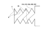
- the seal members 61A and 61D and the pressure equalizing members 63A to 63C may have a bellows shape, and the groove 80 formed on the inner peripheral surface thereof may be formed in a spiral shape.
- the bubbles K remaining in the groove 80 when the lubricant J is injected can be easily obtained by rotating the seal members 61A and 61D and the pressure equalizing members 63A to 63C around the respective central axes. Can be discharged.
- the seal members 61A and 61D and the pressure equalizing members 63A to 63C are rotated so that the bubble K moves along the groove 80 toward the injection port 66.
- the bubbles K discharged from the seal members 61A and 61D and the pressure equalizing members 63A to 63C can be guided to the injection port 66 and discharged to the outside from the injection port 66 (see FIG. 3). If bubbles K remain, even if the pressure equalizing members 63A to 63C and the seal member 61D are contracted by the seawater pressure P1, bubbles having a lower density than the lubricant J are crushed, so the pressure P2 of the lubricant J is efficient. Does not rise well. However, by discharging the bubbles K as described above, it is possible to efficiently equalize the seawater pressure P1 and the lubricant J pressure P2.
- seal members 61A and 61D having the spiral groove 80 may be mounted on the outer sleeve 56 having a tapered inner peripheral surface 56c as shown in FIG. By doing in this way, the bubble which escaped from sealing member 61A, 61D can be smoothly passed through the meshing part S2, and can be moved to the injection port 66 side. Therefore, the remaining of the bubbles K can be further reduced.
- the water current generator 10 was installed in the deep sea was demonstrated, it is not restricted to the deep sea.
- the number of blades 22 of the impeller 20 is not limited to the number described above as long as it is a plurality. In addition to this, for example, other configurations can be appropriately employed for the configuration of each part of the water current generator 10.
- This invention can be applied to an underwater coupling joint and a water current generator.
- the underwater coupling joint and the water current generator to which the present invention is applied can maintain a lubrication state in the underwater coupling joint and can suppress a burden on maintenance.
Landscapes
- Engineering & Computer Science (AREA)
- General Engineering & Computer Science (AREA)
- Mechanical Engineering (AREA)
- Chemical & Material Sciences (AREA)
- Combustion & Propulsion (AREA)
- Power Engineering (AREA)
- Other Liquid Machine Or Engine Such As Wave Power Use (AREA)
- Sealing Devices (AREA)
- Diaphragms And Bellows (AREA)
Abstract
カップリング継手(50)は、ギヤ歯(56g)を有するジョイント部材(52)と、ギヤ歯(56g)と噛み合うギヤ歯(54g)を有し、ギヤ歯(56g)とギヤ歯(54g)を介してジョイント部材(52)との間で回転力を伝達するセンターチューブ(51)と、ジョイント部材(52)とセンターチューブ(51)との間で、ギヤ歯(56g)とギヤ歯(54g)の歯合部(S2)を含む潤滑空間(S)を外部から閉塞するシール部材(61A)と、潤滑空間(S)に充填された潤滑剤(J)と、潤滑空間(S)の一部に面して設けられ、外部の圧力に応じて変形することで、潤滑空間(S)の体積を変化させることによって、潤滑剤(J)の圧力と外部の圧力とを均等化させる均圧部材(63A)と、を備える。
Description
本発明は、水中カップリング継手、水流発電機に関する。
本願は、2015年2月17日に、日本に出願された特願2015-028495号に基づき優先権を主張し、その内容をここに援用する。
本願は、2015年2月17日に、日本に出願された特願2015-028495号に基づき優先権を主張し、その内容をここに援用する。
海や河川等における海流や水流を利用して発電を行う水流発電機は、羽根車と、発電機と、を備えている。羽根車は、外周側に向かって延びる複数のブレード(羽根)を有している。発電機は、回転軸の端部が羽根車に連結され、海流や水流によって回転する羽根車とともに回転軸が回転することで発電を行う。
水中において、羽根車の羽根には海流や水流によって大きな力が作用する。すると、羽根車の中心に連結された回転軸には、軸方向や径方向の力やモーメントが作用する。
発電効率を高めるためには、羽根車の直径、すなわち羽根の長さを大きくする方法が挙げられる。しかし、羽根車から回転軸に作用する力やモーメントが非常に大きくなってしまう。
発電効率を高めるためには、羽根車の直径、すなわち羽根の長さを大きくする方法が挙げられる。しかし、羽根車から回転軸に作用する力やモーメントが非常に大きくなってしまう。
上述した力やモーメントによる影響が羽根車から発電機に及ぶことを防ぐため、羽根車と発電機の回転軸との間に、例えば特許文献1記載のようなカップリング装置が用いられる場合がある。このようなカップリング装置は、その羽根車に近い側と発電機に近い側との軸方向、径方向、傾き方向の相対変位を許容しつつ、羽根車と発電機の回転軸との間で回転力の伝達を行う。
このカップリング装置においては、回転力の伝達にギヤを用いるため、ギヤの歯合部には摩耗抑制のために潤滑剤が必要となる。
特許文献1記載のカップリング装置は、外部からの高い圧力を有する流体が進入することを防ぐために、シール部材を備えている。
このカップリング装置においては、回転力の伝達にギヤを用いるため、ギヤの歯合部には摩耗抑制のために潤滑剤が必要となる。
特許文献1記載のカップリング装置は、外部からの高い圧力を有する流体が進入することを防ぐために、シール部材を備えている。
水中発電機を海中深くに沈めて設置する場合、例えば30気圧(約3MPa)といった高い水圧が作用する。そのため、シール部材によるシール部を通して水中発電機の外部から内部へと海水が流入してしまう可能性がある。この場合、ギヤの歯合部の潤滑剤が流出する可能性が有る。潤滑剤が流出すると、歯合部の摩擦増大によるギヤの損傷等が生じ、水中発電機を利用できなくなってしまう可能性が有る。
これに対し、シール部におけるシール性を維持するために、定期的にシール部材の交換や潤滑剤の供給等を行うことが考えられる。しかし、この場合、メンテナンスに掛かる負担が増大してしまう。さらに、潤滑剤の流出による海洋汚染も懸念される。
この発明は、メンテナンスに掛かる負担を抑えることができる水中カップリング継手、水流発電機を提供することを目的とする。
これに対し、シール部におけるシール性を維持するために、定期的にシール部材の交換や潤滑剤の供給等を行うことが考えられる。しかし、この場合、メンテナンスに掛かる負担が増大してしまう。さらに、潤滑剤の流出による海洋汚染も懸念される。
この発明は、メンテナンスに掛かる負担を抑えることができる水中カップリング継手、水流発電機を提供することを目的とする。
この発明の第一態様によれば、水中カップリング継手は、第一ギヤ歯を有する第一の軸部材を備える。水中カップリング継手は、前記第一ギヤ歯と噛み合う第二ギヤ歯を有し、前記第一ギヤ歯と前記第二ギヤ歯を介して前記第一の軸部材との間で回転力を伝達する第二の軸部材を更に備える。水中カップリング継手は、前記第一の軸部材と前記第二の軸部材との間で、前記第一ギヤ歯と前記第二ギヤ歯の歯合部を含む空間を外部から閉塞するシール部材を更に備える。水中カップリング継手は、前記空間に充填された潤滑剤を更に備える。水中カップリング継手は、前記空間の一部に面して設けられ、前記外部の圧力に応じて変形して前記空間の体積を変化させることによって、前記潤滑剤の圧力と前記外部の圧力とを均等化させる均圧機構を更に備える。
このように構成することで、水中カップリング継手を水中に沈めたときに、水中カップリング装置の外部、すなわち周囲の圧力に応じて、均圧機構を変形させることができる。
この均圧機構の変形により、潤滑剤が充填された空間の体積を変化させて、空間内の潤滑剤の圧力と外部の圧力とを均等化することができる。これにより、シール部材と、第一の軸部材、第二の軸部材のそれぞれとの間に大きな差圧が生じることを抑制できる。その結果、潤滑剤が充填された空間に外部から水が浸入したり、潤滑剤が空間から外部に漏出したりすることを抑制できる。
この均圧機構の変形により、潤滑剤が充填された空間の体積を変化させて、空間内の潤滑剤の圧力と外部の圧力とを均等化することができる。これにより、シール部材と、第一の軸部材、第二の軸部材のそれぞれとの間に大きな差圧が生じることを抑制できる。その結果、潤滑剤が充填された空間に外部から水が浸入したり、潤滑剤が空間から外部に漏出したりすることを抑制できる。
この発明の第二態様によれば、水中カップリング継手は、第一態様における均圧機構が、第一端部が開口し、他端が閉塞した筒状で、前記第一端部と前記他端とが接離する方向に伸縮可能なベローズであってもよい。
このようなベローズを用いることで、外部の圧力を閉塞された他端に作用させることができる。これにより、ベローズを、その開口した第一端部に対して他端が接近する方向に短縮させることができる。さらに、ベローズを、その第一端部に対して他端側が離間する方向に伸長させることができる。これにより、空間の体積が変動し、外部の水と空間内の潤滑剤との各圧力の均等化を図ることができる。
このようなベローズを用いることで、外部の圧力を閉塞された他端に作用させることができる。これにより、ベローズを、その開口した第一端部に対して他端が接近する方向に短縮させることができる。さらに、ベローズを、その第一端部に対して他端側が離間する方向に伸長させることができる。これにより、空間の体積が変動し、外部の水と空間内の潤滑剤との各圧力の均等化を図ることができる。
この発明の第三態様によれば、水中カップリング継手は、第二態様におけるベローズが、内周面に螺旋状の溝を有しているようにしてもよい。
このように構成することで、空間内に潤滑剤を充填した際に、ベローズを中心軸周りに回転させることで、溝の内側に残存した気泡を螺旋状の溝に沿って移動させることができる。そのため、溝の内側に残存した気泡を、開口したベローズの第一端部から排出させることができる。
このように構成することで、空間内に潤滑剤を充填した際に、ベローズを中心軸周りに回転させることで、溝の内側に残存した気泡を螺旋状の溝に沿って移動させることができる。そのため、溝の内側に残存した気泡を、開口したベローズの第一端部から排出させることができる。
この発明の第四態様によれば、水中カップリング継手は、第一から第三態様の何れか一つの態様において、前記第一の軸部材および前記第二の軸部材の一方の内部に、前記外部の圧力が導入される外圧導入部が設けられていてもよい。さらに、前記均圧機構は前記外圧導入部に設けられているようにしてもよい。
このように構成することで、外部の圧力を、外圧導入部を介して均圧機構に作用させることができる。そのため、外部の水と空間内の潤滑剤との圧力の均等化を図ることができる。
外圧導入部を、第一の軸部材および第二の軸部材の一方の内部に設けることで、スペースの有効利用を図ることができる。さらに、均圧機構を外圧導入部に設けることで、均圧機構が外部に露出しないため、不用意な接触等により均圧機構が損傷することを抑制できる。
このように構成することで、外部の圧力を、外圧導入部を介して均圧機構に作用させることができる。そのため、外部の水と空間内の潤滑剤との圧力の均等化を図ることができる。
外圧導入部を、第一の軸部材および第二の軸部材の一方の内部に設けることで、スペースの有効利用を図ることができる。さらに、均圧機構を外圧導入部に設けることで、均圧機構が外部に露出しないため、不用意な接触等により均圧機構が損傷することを抑制できる。
この発明の第五態様によれば、水中カップリング継手は、第一から第三態様の何れか一つの態様において、前記第一の軸部材および前記第二の軸部材の一方に、前記空間に前記外部から潤滑剤を注入する注入口を備えていてもよい。前記均圧機構は、前記注入口に設けられていてもよい。
このように構成することで、均圧機構を潤滑剤の注入口に設けると、外部の圧力は注入口を介して均圧機構に作用して、外部の水と空間内の潤滑剤との圧力の均等化を図ることができる。これにより、均圧機構を設けるための部位を別途設ける必要がない。
このように構成することで、均圧機構を潤滑剤の注入口に設けると、外部の圧力は注入口を介して均圧機構に作用して、外部の水と空間内の潤滑剤との圧力の均等化を図ることができる。これにより、均圧機構を設けるための部位を別途設ける必要がない。
この発明の第六態様によれば、水中カップリング継手は、第一から第三態様の何れか一つの態様において、前記シール部材が前記外部の圧力に応じて変形可能に形成され、前記均圧機構を兼ねるようにしてもよい。
このように、シール部材が均圧機構を兼ねることで、部品点数を抑えることができる。
このように、シール部材が均圧機構を兼ねることで、部品点数を抑えることができる。
この発明の第七態様によれば、水中カップリング継手は、第一から第六態様の何れか一つの態様において、前記シール部材が前記第一の軸部材および前記第二の軸部材に接合されているようにしてもよい。
このように、シール部材を第一の軸部材、第二の軸部材に接合することで、潤滑剤が充填された空間に外部から水が浸入したり、潤滑剤が空間から外部に漏出したりすることを抑制できる。
このように、シール部材を第一の軸部材、第二の軸部材に接合することで、潤滑剤が充填された空間に外部から水が浸入したり、潤滑剤が空間から外部に漏出したりすることを抑制できる。
この発明の第八態様によれば、水流発電機は、複数の翼を備えた羽根車と、前記羽根車によって駆動される発電機と、前記羽根車の回転軸と前記発電機の入力軸とを連結する、上記したような水中カップリング継手と、を備える。
このように構成することで、水中カップリング継手において、潤滑剤が充填された空間に外部から水が浸入したり、潤滑剤が空間から外部に漏出したりすることを抑制できる。
このように構成することで、水中カップリング継手において、潤滑剤が充填された空間に外部から水が浸入したり、潤滑剤が空間から外部に漏出したりすることを抑制できる。
上述した水中カップリング継手、水流発電機によれば、水中カップリング継手における潤滑状態を維持し、メンテナンスに掛かる負担を抑えることができる。
(第一実施形態)
図1は、この実施形態の水流発電機を示す斜視図である。図2は、上記水流発電機の実施形態における羽根車とナセルとの連結部分の構成を示す断面図である。
図1に示すように、この実施形態における水流発電機10は、海底や水中構造物等に、係留索(図示無し)を介して係留されることで、深度の大きい海水中に設置されている。
この水流発電機10は、羽根車20と、ナセル30と、を備えている。
羽根車20は、ハブ21と、ブレード22と、を備えている。
図1は、この実施形態の水流発電機を示す斜視図である。図2は、上記水流発電機の実施形態における羽根車とナセルとの連結部分の構成を示す断面図である。
図1に示すように、この実施形態における水流発電機10は、海底や水中構造物等に、係留索(図示無し)を介して係留されることで、深度の大きい海水中に設置されている。
この水流発電機10は、羽根車20と、ナセル30と、を備えている。
羽根車20は、ハブ21と、ブレード22と、を備えている。
図1、図2に示すように、ハブ21は、羽根車20の中央部に配置されている。ハブ21は、先端21aに向かって外径が漸次縮小するいわゆる砲弾状に形成されている。このハブ21は、先端21aと反対側に、端面21bを有している。端面21bは、羽根車20の回転中心軸C(以下、単に軸線Cと称する)に直交する。ハブ21の端面21bの外周部に、筒状部21cが一体に設けられている。筒状部21cは、軸線Cの延びる方向(以下、単に軸線C方向と称する)で先端21aと反対側に向かって延びる円筒状に形成されている。ハブ21の端面21bには、シャフト(回転軸)23が一体に取り付けられている。このシャフト23は、軸線C方向で先端21aとは反対側に向けて突出している。
ブレード22は、ハブ21の外周部に、周方向に間隔をあけて複数本設けられている。
この実施形態においては、2本のブレード22が設けられている。これら2本のブレード22は、それぞれ回転対称な位置に配されている。各ブレード22は、基端部22aがハブ21の筒状部21cに一体に固定されている。各ブレード22は、その先端部22bに向かってハブ21から放射方向外側に延びている。
この実施形態においては、2本のブレード22が設けられている。これら2本のブレード22は、それぞれ回転対称な位置に配されている。各ブレード22は、基端部22aがハブ21の筒状部21cに一体に固定されている。各ブレード22は、その先端部22bに向かってハブ21から放射方向外側に延びている。
ナセル30は、ケーシング31と、発電機32と、メインシャフト33と、を備えている。
ケーシング31は、軸線C方向に延びる円筒状に形成されている。このケーシング31は、その第一端部31aに羽根車支持部34が設けられている。羽根車支持部34は、羽根車20を回転自在に支持する。羽根車支持部34の外周面には、軸線C方向に間隔をあけて、一対の外部軸受35が設けられている。羽根車20は、これら外部軸受35を介して、羽根車支持部34に回転自在に支持されている。各外部軸受35は、例えば、樹脂で形成され、周囲の海水を潤滑剤として羽根車20を回転自在に支持する、いわゆる滑り軸受として機能する。
ケーシング31は、軸線C方向に延びる円筒状に形成されている。このケーシング31は、その第一端部31aに羽根車支持部34が設けられている。羽根車支持部34は、羽根車20を回転自在に支持する。羽根車支持部34の外周面には、軸線C方向に間隔をあけて、一対の外部軸受35が設けられている。羽根車20は、これら外部軸受35を介して、羽根車支持部34に回転自在に支持されている。各外部軸受35は、例えば、樹脂で形成され、周囲の海水を潤滑剤として羽根車20を回転自在に支持する、いわゆる滑り軸受として機能する。
ケーシング31内には、隔壁36が設けられている。この隔壁36は、軸線Cに直交し、且つ、軸線C方向で第一端部31aとは反対側(以下、単に第二端部側と称する)を向く平面を有している。ケーシング31内には、軸線C方向で隔壁36よりも第二端部側に、密閉された発電機室37が形成されている。この発電機室37内は、空気雰囲気とされている。発電機室37には、発電機32が収容されている。
発電機32は、入力軸32aを備えている。入力軸32aは、軸線Cに沿って隔壁36に近い側に突出する。この発電機32は、入力軸32aと一体に設けられたロータ(図示無し)と、ロータに対向するステータ(図示無し)と、を備えている。発電機32は、入力軸32aとともにロータがステータに対して相対的に回転することで発電する。この発電機32によって発電された電力は、送電線(図示せず)を介して外部に供給される。
発電機32の入力軸32aには、増速器(図示無し)、ブレーキ(図示無し)等を介してメインシャフト33が連結される。
メインシャフト33は、隔壁36に形成されたシャフト孔36hを通じて羽根車支持部34内に延びている。これらメインシャフト33とシャフト孔36hとの間には、リング状のシール部材38が設けられている。シール部材38は、メインシャフト33周りから発電機室37内への浸水を防止している。
メインシャフト33は、隔壁36に形成されたシャフト孔36hを通じて羽根車支持部34内に延びている。これらメインシャフト33とシャフト孔36hとの間には、リング状のシール部材38が設けられている。シール部材38は、メインシャフト33周りから発電機室37内への浸水を防止している。
メインシャフト33と、羽根車20のハブ21に設けられたシャフト23との間には、カップリング継手(水中カップリング継手)50が設けられている。このカップリング継手50を介してメインシャフト33とシャフト23とが接続されている。
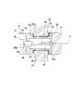
図3は、第一実施形態における水中カップリング継手の構成を示す断面図である。
図3に示すように、カップリング継手50は、センターチューブ(第二の軸部材)51と、ジョイント部材(第一の軸部材)52と、シール部60Aと、を備えている。ジョイント部材52は、センターチューブ51の両端にそれぞれ設けられている。
図3に示すように、カップリング継手50は、センターチューブ(第二の軸部材)51と、ジョイント部材(第一の軸部材)52と、シール部60Aと、を備えている。ジョイント部材52は、センターチューブ51の両端にそれぞれ設けられている。
センターチューブ51は、筒状に形成されている。センターチューブ51の両端部には、インナーギヤ54が一体に設けられている。インナーギヤ54は、センターチューブ51の外周面に沿って連続する円環状に形成されている。インナーギヤ54は、その外周部にギヤ歯(第二ギヤ歯)54gを備えている。ここで、ギヤ歯54gは、外周部に形成された歯面54tの断面形状が、軸線Cに沿うギヤ幅方向の両端部54aに対し、中央部54bが外周側に向かって膨出するように凸状に湾曲している。
ジョイント部材52は、円板状の2つのジョイントプレート55と、筒状の2つのアウタースリーブ56と、を一体に備えている。
2つのジョイントプレート55のうち一方は、メインシャフト33に一体に連結されている。2つのジョイントプレート55のうち他方は、シャフト23に一体に連結されている。
2つのジョイントプレート55のうち一方は、メインシャフト33に一体に連結されている。2つのジョイントプレート55のうち他方は、シャフト23に一体に連結されている。
アウタースリーブ56は、それぞれジョイントプレート55に対して一体に設けられている。アウタースリーブ56は、ジョイントプレート55のセンターチューブ51に対向する面側に設けられている。これらアウタースリーブ56の内周側には、センターチューブ51のインナーギヤ54が配されている。アウタースリーブ56は、その内周面に、インナーギヤ54のギヤ歯54gに噛み合う平歯状のギヤ歯(第一ギヤ歯)56gを有している。
ジョイント部材52は、凸状に湾曲したギヤ歯54gと平歯状のギヤ歯56gとの噛み合いにより、センターチューブ51に対して軸線C方向に相対変位可能とされる。ジョイント部材52は、上記ギヤ歯54gとギヤ歯56gとの噛み合いにより、互いに軸線Cに対して傾斜する方向に変位可能となる。
つまり、シャフト23を有した羽根車20は、メインシャフト33に対して軸線C方向に相対変位すること、および、互いに傾斜することが許容されている。
センターチューブ51の両端のギヤ歯54gにそれぞれジョイント部材52が連結されている。そのため、シャフト23は、一方のジョイント部材52の中心軸に対して他方のジョイント部材52の中心軸が平行状態を保ったまま、メインシャフト33に対して径方向に偏心することが許容されている。
センターチューブ51の両端のギヤ歯54gにそれぞれジョイント部材52が連結されている。そのため、シャフト23は、一方のジョイント部材52の中心軸に対して他方のジョイント部材52の中心軸が平行状態を保ったまま、メインシャフト33に対して径方向に偏心することが許容されている。
シール部60Aは、それぞれ、シール部材61Aと、外圧導入部62Aと、均圧部材(均圧機構)63Aと、を備えている。
シール部材61Aは、センターチューブ51の外周面51fと、センターチューブ51の両端部の外周側に位置するアウタースリーブ56との間を、水密性を保って塞ぐ。シール部材61Aは、軸線C方向に伸縮可能な蛇腹状に形成されている。これらシール部材61Aは、金属製である。シール部材61Aの第一端部61aは、センターチューブ51の外周面51fに対して、シール溶接や摩擦接合等により接合されている。同様に、シール部材61Aの第二端部61bは、アウタースリーブ56に対して、シール溶接や摩擦接合等により接合されている。これらシール部材61Aは、メインシャフト33に対するシャフト23の軸方向、径方向、および、傾斜方向の相対変位に追従して変形し、シール状態を維持することが可能となっている。
シール部材61Aは、センターチューブ51の外周面51fと、センターチューブ51の両端部の外周側に位置するアウタースリーブ56との間を、水密性を保って塞ぐ。シール部材61Aは、軸線C方向に伸縮可能な蛇腹状に形成されている。これらシール部材61Aは、金属製である。シール部材61Aの第一端部61aは、センターチューブ51の外周面51fに対して、シール溶接や摩擦接合等により接合されている。同様に、シール部材61Aの第二端部61bは、アウタースリーブ56に対して、シール溶接や摩擦接合等により接合されている。これらシール部材61Aは、メインシャフト33に対するシャフト23の軸方向、径方向、および、傾斜方向の相対変位に追従して変形し、シール状態を維持することが可能となっている。
外圧導入部62Aは、海水導入部64Aと、導圧孔65Aとを備えている。
海水導入部64Aは、外圧導入部62Aの中心軸に沿って延びる円柱状の通路である。
導圧孔65Aは、海水導入部64Aをその厚さ方向に貫通するように形成されている。
この導圧孔65Aによって、センターチューブ51の外部と海水導入部64Aとが連通されている。これにより、水流発電機10を水中に沈めた状態では、導圧孔65Aを介して海水導入部64Aに海水が流れ込むようになっている。
海水導入部64Aは、外圧導入部62Aの中心軸に沿って延びる円柱状の通路である。
導圧孔65Aは、海水導入部64Aをその厚さ方向に貫通するように形成されている。
この導圧孔65Aによって、センターチューブ51の外部と海水導入部64Aとが連通されている。これにより、水流発電機10を水中に沈めた状態では、導圧孔65Aを介して海水導入部64Aに海水が流れ込むようになっている。
均圧部材63Aは、金属製であり、蛇腹状に形成されている。均圧部材63Aは、第一端部63aが閉塞され、第二端部63bが開口している。均圧部材63Aは、軸線C方向における海水導入部64Aの両端部にそれぞれ配置されている。これら均圧部材63Aの第二端部63bは、それぞれ海水導入部64Aの両端部を塞ぐようにして嵌め込まれている。均圧部材63Aの第一端部63aは、センターチューブ51の中心軸に直交する平坦面とされている。
ジョイント部材52のアウタースリーブ56は、その外周面56aと内周面56bとを連通する2つの注入口66を備えている。例えば、水流発電機10の組立時、注入口66を通じて、アウタースリーブ56の外周面56aに近い側から、ジョイント部材52のジョイントプレート55と、アウタースリーブ56と、インナーギヤ54とにより形成される隙間S1に、潤滑剤Jが注入充填される。この隙間S1は、ギヤ歯54gおよびギヤ歯56gの歯合部S2を通してシール部材61A内の空間S3に連通している。隙間S1は、均圧部材63A内の空間S4に連通している。これらの隙間S1と、歯合部S2と、空間S3と、空間S4とから潤滑空間(空間)Sが構成されている。潤滑剤Jは、この潤滑空間Sに充填されている。注入口66は、潤滑剤Jの充填後、キャップ(図示無し)の装着、溶接等によって閉塞される。
このような構成のシール部60Aにおいては、水流発電機10のナセル30を水中に沈めると、導圧孔65Aから海水導入部64Aに海水が流れ込む。すると、海水導入部64A内の海水の圧力P1が、均圧部材63Aの第一端部63aに作用する。均圧部材63Aは、第一端部63aに作用する海水の圧力P1と、均圧部材63A内の空間S4の潤滑剤Jの圧力P2とがバランスするように、第一端部63aが第二端部63bに対して接近および離間する方向に伸縮する。例えば、ナセル30の水中深度が大きくなり、海水の圧力P1が潤滑剤Jの圧力P2よりも大きくなると、蛇腹状の均圧部材63Aは、その第一端部63aが第二端部63bに接近するように縮む。これにより、ナセル30の周囲の海水の圧力P1と、潤滑空間Sに充填されている潤滑剤Jの圧力P2とが均等になる。
上述した第一実施形態によれば、カップリング継手50を水中に沈めたときに、海水から作用する圧力に応じて均圧部材63Aが変形する。そのため、潤滑空間Sの圧力と外部の圧力とを均等化することができる。これにより、シール部材61Aに対して外部から大きな圧力が作用することを抑制できる。そのため、潤滑剤Jが充填された潤滑空間Sに外部から水が浸入したり、潤滑剤Jが潤滑空間Sから外部に漏出したりすることを抑制できる。
その結果、カップリング継手50における潤滑状態を維持し、メンテナンスに掛かる負担を抑えることが可能となる。
その結果、カップリング継手50における潤滑状態を維持し、メンテナンスに掛かる負担を抑えることが可能となる。
さらに、外圧導入部62Aをセンターチューブ51の内部に設けることで、スペースの有効利用を図ることができる。均圧部材63Aを外圧導入部62Aに設けることで、均圧部材63Aが外部に露出せず、不用意な接触等による均圧部材63Aの損傷を抑制できる。
さらに、均圧部材63Aが、金属製であるため、十分な強度を容易に確保できる。これにより、海水の高い圧力P1による均圧部材63Aの破損を抑制できる。
さらに、均圧部材63Aは蛇腹状をなしているので、第一端部63aが第二端部63bに対して接近および離間することによる内部の空間S4の体積変動量を大きくすることができる。
これにより、水流発電機10の設置深度が大きい場合にも、その水中深度に応じて高くなる海水の圧力P1に応じて均圧部材63Aを縮ませることができる。これにより、潤滑剤Jの圧力P2との均等化を容易に図ることができる。そのため、Oリング等によりシールする場合と比較して、より大きな調整代を確保することができる。
さらに、均圧部材63Aは蛇腹状をなしているので、第一端部63aが第二端部63bに対して接近および離間することによる内部の空間S4の体積変動量を大きくすることができる。
これにより、水流発電機10の設置深度が大きい場合にも、その水中深度に応じて高くなる海水の圧力P1に応じて均圧部材63Aを縮ませることができる。これにより、潤滑剤Jの圧力P2との均等化を容易に図ることができる。そのため、Oリング等によりシールする場合と比較して、より大きな調整代を確保することができる。
さらに、シール部材61Aがアウタースリーブ56およびセンターチューブ51に接合されているため、潤滑剤Jが充填された潤滑空間Sに外部から水が浸入したり、潤滑剤Jが潤滑空間Sから外部に漏出したりすることを低減できる。
(第二実施形態)
次に、この発明の第二実施形態における水中カップリング継手、水流発電機を図面に基づき説明する。この第二実施形態は、第一実施形態と外圧導入部62B、均圧部材63Bの構成のみが異なるので、第一実施形態と同一部分に同一符号を付して説明するとともに、重複説明を省略する。
次に、この発明の第二実施形態における水中カップリング継手、水流発電機を図面に基づき説明する。この第二実施形態は、第一実施形態と外圧導入部62B、均圧部材63Bの構成のみが異なるので、第一実施形態と同一部分に同一符号を付して説明するとともに、重複説明を省略する。
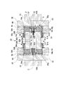
図4は、この発明の第二実施形態における水中カップリング継手の構成を示す断面図である。
図4に示すように、この実施形態におけるカップリング継手50は、センターチューブ51と、ジョイント部材52と、シール部60Bと、を備えている。
シール部60Bは、シール部材61Aと、外圧導入部62Bと、均圧部材(均圧機構)63Bと、を備えている。
図4に示すように、この実施形態におけるカップリング継手50は、センターチューブ51と、ジョイント部材52と、シール部60Bと、を備えている。
シール部60Bは、シール部材61Aと、外圧導入部62Bと、均圧部材(均圧機構)63Bと、を備えている。
シール部材61Aは、センターチューブ51の外周面51fと、センターチューブ51の両端部の外周側に位置するアウタースリーブ56との間を、水密性を保って塞ぐ。
外圧導入部62Bは、海水導入部64Bと、導圧孔65Bとを有している。
海水導入部64Bは、カップリング継手50の両側のジョイントプレート55と、各ジョイントプレート55に接合されたメインシャフト33、および、シャフト23とに渡って、それぞれ軸線C方向に連続するように形成されている。
導圧孔65Bは、メインシャフト33、および、シャフト23をそれぞれ貫通して形成されている。この導圧孔65Bによって、メインシャフト33、および、シャフト23の外部と、海水導入部64Bと、が連通されている。
海水導入部64Bは、カップリング継手50の両側のジョイントプレート55と、各ジョイントプレート55に接合されたメインシャフト33、および、シャフト23とに渡って、それぞれ軸線C方向に連続するように形成されている。
導圧孔65Bは、メインシャフト33、および、シャフト23をそれぞれ貫通して形成されている。この導圧孔65Bによって、メインシャフト33、および、シャフト23の外部と、海水導入部64Bと、が連通されている。
均圧部材63Bは、金属製の蛇腹状に形成されている。均圧部材63Bは、第一端部63a側が閉塞され、第二端部63b側が開放されている。均圧部材63Bは、第二端部63bが隙間S1に面するようにして海水導入部64Bの端部に設けられている。
このような構成のシール部60Bにおいては、水流発電機10のナセル30を水中に沈めると、導圧孔65Bから海水導入部64Bに海水が流れ込む。すると、海水導入部64B内の海水の圧力が、均圧部材63Bの第一端部63aに作用する。ナセル30の水中深度が大きくなり、海水の圧力P1が潤滑剤Jの圧力P2よりも大きくなると、蛇腹状の均圧部材63Bは、第一端部63aが第二端部63bに接近する方向に縮む。これにより、ナセル30の周囲の海水の圧力P1と、潤滑空間Sに充填されている潤滑剤Jの圧力P2とが均等となる。
上述した第二実施形態によれば、外部の水が外圧導入部62Bに導入されることによって、外部の圧力が均圧部材63Bに作用する。そのため、外部の水と潤滑空間S内の潤滑剤Jとの圧力の均等化を図ることができる。
これにより、シール部材61Aに対して外部から大きな圧力が作用することを抑制できる。そのため、潤滑剤Jが充填された潤滑空間Sに外部から水が浸入したり、潤滑剤Jが潤滑空間Sから外部に漏出したりすることを抑制できる。
その結果、カップリング継手50における潤滑状態を維持し、メンテナンスに掛かる負担を抑えることが可能となる。
これにより、シール部材61Aに対して外部から大きな圧力が作用することを抑制できる。そのため、潤滑剤Jが充填された潤滑空間Sに外部から水が浸入したり、潤滑剤Jが潤滑空間Sから外部に漏出したりすることを抑制できる。
その結果、カップリング継手50における潤滑状態を維持し、メンテナンスに掛かる負担を抑えることが可能となる。
さらに、外圧導入部62Bを、ジョイント部材52と、メインシャフト33、および、シャフト23との内部にそれぞれ設けることで、スペースの有効利用を図ることができる。
さらに、均圧部材63Bを外圧導入部62Bに設けることで、均圧部材63Bが外部に露出せず、不用意な接触等による均圧部材63Aの損傷を抑制できる。
さらに、均圧部材63Bを外圧導入部62Bに設けることで、均圧部材63Bが外部に露出せず、不用意な接触等による均圧部材63Aの損傷を抑制できる。
(第三実施形態)
次に、この発明にかかる水中カップリング継手、水流発電機の第三実施形態について説明する。この第三実施形態は、第一実施形態と外圧導入部62C、および、均圧部材63Cの構成のみが異なる。そのため、第一、第二実施形態と同一部分に同一符号を付して説明するとともに、重複説明を省略する。
次に、この発明にかかる水中カップリング継手、水流発電機の第三実施形態について説明する。この第三実施形態は、第一実施形態と外圧導入部62C、および、均圧部材63Cの構成のみが異なる。そのため、第一、第二実施形態と同一部分に同一符号を付して説明するとともに、重複説明を省略する。
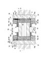
図5は、この発明の第三実施形態における水中カップリング継手の構成を示す断面図である。
図5に示すように、この実施形態におけるカップリング継手50は、センターチューブ51と、ジョイント部材52と、シール部60Cと、を備えている。
シール部60Cは、シール部材61Aと、外圧導入部62Cと、均圧部材(均圧機構)63Cと、を備えている。
図5に示すように、この実施形態におけるカップリング継手50は、センターチューブ51と、ジョイント部材52と、シール部60Cと、を備えている。
シール部60Cは、シール部材61Aと、外圧導入部62Cと、均圧部材(均圧機構)63Cと、を備えている。
シール部材61Aは、センターチューブ51の外周面51fと、センターチューブ51の両端部の外周側に位置するアウタースリーブ56との間を、水密性を保って塞ぐ。
この実施形態における外圧導入部62Cは、潤滑空間Sに潤滑剤Jを注入するために形成された注入口66を兼ねる。この注入口66は、ジョイント部材52のアウタースリーブ56に形成されている。
均圧部材63Cは、蛇腹状に形成されている。均圧部材63Cは、金属製である。均圧部材63Cは、第一端部63a側が閉塞されるとともに、第二端部63b側が開放されている。均圧部材63Cは、注入口66に設けられている。均圧部材63Cは、開放された第二端部63bがアウタースリーブ56の外周側を向くようにして設けられている。この均圧部材63Cは、潤滑剤Jの注入後に注入口66を閉塞するキャップとしても機能している。
均圧部材63Cは、蛇腹状に形成されている。均圧部材63Cは、金属製である。均圧部材63Cは、第一端部63a側が閉塞されるとともに、第二端部63b側が開放されている。均圧部材63Cは、注入口66に設けられている。均圧部材63Cは、開放された第二端部63bがアウタースリーブ56の外周側を向くようにして設けられている。この均圧部材63Cは、潤滑剤Jの注入後に注入口66を閉塞するキャップとしても機能している。
このような構成のシール部60Cにおいては、水流発電機10のナセル30を水中に沈めると、外圧導入部62Cである注入口66に海水が流れ込む。すると、海水導入部64C内の海水の圧力が、均圧部材63Cの第一端部63aに作用する。ナセル30の水中深度が大きくなり、海水の圧力P1が潤滑剤Jの圧力P2よりも大きくなると、蛇腹状の均圧部材63Cは、第一端部63aが第二端部63bから離間する方向に伸びる。これにより、ナセル30の周囲の海水の圧力P1と、潤滑空間Sに充填されている潤滑剤Jの圧力P2とが均等となる。
上述した第三実施形態によれば、カップリング継手50を水中に沈めたときに、海水の圧力P1に応じて、均圧部材63Cが変形する。これにより、潤滑空間S内の潤滑剤Jの圧力と外部の圧力とが均等化する。そのため、シール部材61Aに対して外部から大きな圧力が作用することを抑制できる。これによい、潤滑剤Jが充填された潤滑空間Sに外部から水が浸入したり、潤滑剤Jが潤滑空間Sから外部に漏出したりすることを抑制できる。
その結果、カップリング継手50における潤滑状態を維持し、メンテナンスに掛かる負担を抑えることが可能となる。
その結果、カップリング継手50における潤滑状態を維持し、メンテナンスに掛かる負担を抑えることが可能となる。
さらに、均圧部材63Cが潤滑剤Jの注入口66に設けられていることで、均圧部材63Cを設けるための部位を別途設ける必要がない。すなわち、上記第一、第二実施形態に示した構成のように、導圧孔65A,65B、海水導入部64A,64Bを形成する必要がない。さらに、均圧部材63Cが注入口66を閉塞するキャップを兼ねている。
その結果、シール部60Cを構成する部品点数を減らすことができるとともに、漏洩が発生する可能性のある箇所を減らして漏洩の可能性をさらに低減することができる。
その結果、シール部60Cを構成する部品点数を減らすことができるとともに、漏洩が発生する可能性のある箇所を減らして漏洩の可能性をさらに低減することができる。
上記第一から第三実施形態においては、シール部材61Aを伸縮可能な蛇腹状とした。しかし、シール部材61Aは、Oリング等、他のシール部材に代替してもよい。
(第四実施形態)
次に、この発明にかかる水中カップリング継手、水流発電機の第四実施形態について説明する。以下に説明する第四実施形態においては、第一から第三実施形態と同一部分に同一符号を付して説明するとともに、重複説明を省略する。
次に、この発明にかかる水中カップリング継手、水流発電機の第四実施形態について説明する。以下に説明する第四実施形態においては、第一から第三実施形態と同一部分に同一符号を付して説明するとともに、重複説明を省略する。
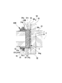
図6は、この発明の第四実施形態における水中カップリング継手の構成を示す断面図である。
図6に示すように、この実施形態におけるカップリング継手50は、センターチューブ51と、ジョイント部材52と、シール部60Dと、を備えている。
シール部60Dは、シール部材61Dを備えている。
図6に示すように、この実施形態におけるカップリング継手50は、センターチューブ51と、ジョイント部材52と、シール部60Dと、を備えている。
シール部60Dは、シール部材61Dを備えている。
シール部材61Dは、軸線C方向に伸縮可能な蛇腹状に形成されている。これらシール部材61Dは、金属製であり、センターチューブ51の外周面51fと、センターチューブ51の両端部の外周側に位置するアウタースリーブ56との間を、水密性を保って塞ぐ。
シール部材61Dは、アウタースリーブ56に近づくに従って、その外径が漸次拡大するテーパー状に形成されている。このようにテーパー状に形成されたシール部材61Dでは、海水の圧力P1が、センターチューブ51の軸方向にも作用する。
この実施形態においては、このシール部材61Dが、均圧部材(均圧機構)63Dを兼ねている。すなわち、水流発電機10のナセル30を水中に沈めると、シール部材61Dに作用する海水の圧力P1により、シール部材61Dが軸方向に僅かに押圧されて、例えば、第一端部61aが第二端部61bに接近する方向に縮む。これにより、ナセル30の周囲の海水の圧力P1と、シール部材61D内の潤滑空間S5内の潤滑剤Jの圧力P2とが均等となる。
上述した第四実施形態によれば、シール部材61Dが外部の圧力に応じて変形可能とされて、均圧部材63Dを兼ねている。
これにより、上記第一、第二実施形態に示した構成のように、導圧孔65A,65B、海水導入部64A,64Bを形成したり、均圧部材63A~63Cを設けたりする必要がない。
その結果、シール部60Dを構成する部品点数を減らすことができる。さらに、漏洩が発生する可能性のある箇所を減らして漏洩の可能性をさらに低減することができる。
これにより、上記第一、第二実施形態に示した構成のように、導圧孔65A,65B、海水導入部64A,64Bを形成したり、均圧部材63A~63Cを設けたりする必要がない。
その結果、シール部60Dを構成する部品点数を減らすことができる。さらに、漏洩が発生する可能性のある箇所を減らして漏洩の可能性をさらに低減することができる。
上記第一実施形態と同様、カップリング継手50を水中に沈めたときに、海水の圧力P1に応じて、シール部材61Dが変形する。そのため、潤滑空間S内の潤滑剤Jの圧力P2と外部の圧力P1とを均等化することができる。これにより、シール部材61Dに外部から大きな圧力が作用することを抑制できる。その結果、潤滑剤Jが充填された潤滑空間Sに外部から水が浸入したり、潤滑剤Jが潤滑空間Sから外部に漏出したりすることを抑制できる。
上記第四実施形態においては、シール部材61Dを蛇腹状としたが、これに限らない。海水の圧力P1に応じて、シール部材61Dの内側の体積が変化するのであれば、いかなる構成のものを用いてもよい。
例えば、図7に示すように、蛇腹状のシール部材61Dの外径を、海水の圧力P1が作用する方向に向かって段階的に拡大し、海水の圧力P1を受ける受圧面70を設けるようにしてもよい。
この構成により、海水の圧力P1によるシール部材61Dの伸縮変形を効率よく行うことができる。このように、外径を段階的に拡大する構成は、均圧部材63A~63Cについても同様に適用することが可能である。
例えば、図7に示すように、蛇腹状のシール部材61Dの外径を、海水の圧力P1が作用する方向に向かって段階的に拡大し、海水の圧力P1を受ける受圧面70を設けるようにしてもよい。
この構成により、海水の圧力P1によるシール部材61Dの伸縮変形を効率よく行うことができる。このように、外径を段階的に拡大する構成は、均圧部材63A~63Cについても同様に適用することが可能である。
(その他の変形例)
この発明は、上述した実施形態に限定されるものではなく、この発明の趣旨を逸脱しない範囲において、上述した実施形態に種々の変更を加えたものを含む。すなわち、実施形態で挙げた具体的な形状や構成等は一例にすぎず、適宜変更が可能である。
第一から第三実施形態では、蛇腹状のシール部材61A、および均圧部材63A~63Cを用いるようにした。しかし、これら蛇腹状のシール部材61A、および均圧部材63A~63Cの外径は、海水の圧力P1が作用する方向に漸次拡大するようにしてもよい。
この発明は、上述した実施形態に限定されるものではなく、この発明の趣旨を逸脱しない範囲において、上述した実施形態に種々の変更を加えたものを含む。すなわち、実施形態で挙げた具体的な形状や構成等は一例にすぎず、適宜変更が可能である。
第一から第三実施形態では、蛇腹状のシール部材61A、および均圧部材63A~63Cを用いるようにした。しかし、これら蛇腹状のシール部材61A、および均圧部材63A~63Cの外径は、海水の圧力P1が作用する方向に漸次拡大するようにしてもよい。
図8に示すように、シール部材61A,61D、および均圧部材63A~63Cを蛇腹状とし、その内周面に形成される溝80を、螺旋状に形成してもよい。このような構成にすることで、潤滑剤Jの注入時に溝80内に残存する気泡Kを、シール部材61A,61D、および均圧部材63A~63Cを各中心軸周りに回転させることで、容易に排出することができる。ここで、シール部材61A,61D、および均圧部材63A~63Cは、気泡Kが溝80に沿って注入口66側に移動するように回転させる。これにより、シール部材61A,61D、および均圧部材63A~63Cから排出した気泡Kを、注入口66に導いて、注入口66(図3参照)から外部に排出することができる。
仮に気泡Kが残存している場合、海水の圧力P1によって均圧部材63A~63C、シール部材61Dが縮んでも、潤滑剤Jよりも密度の低い気泡が潰れるので、潤滑剤Jの圧力P2が効率よく上昇しない。しかし、上述したように気泡Kを排出することによって、海水の圧力P1と潤滑剤Jの圧力P2との均等化を効率よく図ることが可能となる。
仮に気泡Kが残存している場合、海水の圧力P1によって均圧部材63A~63C、シール部材61Dが縮んでも、潤滑剤Jよりも密度の低い気泡が潰れるので、潤滑剤Jの圧力P2が効率よく上昇しない。しかし、上述したように気泡Kを排出することによって、海水の圧力P1と潤滑剤Jの圧力P2との均等化を効率よく図ることが可能となる。
さらには、螺旋状の溝80を有したシール部材61A,61Dは、図9に示すように、テーパー状の内周面56cを有したアウタースリーブ56に装着してもよい。このようにすることで、シール部材61A,61Dから抜けた気泡を、歯合部S2を円滑に通り抜けさせて注入口66側に移動させることができる。そのため、気泡Kの残存をより一層低減できる。
上述した各実施形態、および、各変形例においては、水流発電機10が深海に設置される場合について説明したが、深海に限られるものではない。
羽根車20のブレード22の枚数は、複数枚であれば、上述した枚数に限られない。
これ以外にも、例えば、水流発電機10の各部の構成等については、適宜他の構成を採用することが可能である。
羽根車20のブレード22の枚数は、複数枚であれば、上述した枚数に限られない。
これ以外にも、例えば、水流発電機10の各部の構成等については、適宜他の構成を採用することが可能である。
この発明は、水中カップリング継手、水流発電機に適用できる。この発明を適用した水中カップリング継手、水流発電機は、水中カップリング継手における潤滑状態を維持し、メンテナンスに掛かる負担を抑えることができる。
10 水流発電機
20 羽根車
21 ハブ
21a 先端
21b 端面
21c 筒状部
22 ブレード
22a 基端部
22b 先端部
23 シャフト(回転軸)
30 ナセル
31 ケーシング
31a 第一端部
31b 第二端部
32 発電機
32a 入力軸
33 メインシャフト
33a 第一端部
33b 第二端部
34 羽根車支持部
35 外部軸受
36 隔壁
36h シャフト孔
37 発電機室
38 シール部材
50 カップリング継手(水中カップリング継手)
51 センターチューブ(第二の軸部材)
51f 外周面
52 ジョイント部材(第一の軸部材)
54 インナーギヤ
54a 端部
54b 中央部
54g ギヤ歯
54t 歯面
55 ジョイントプレート
56 アウタースリーブ
56a 外周面
56b 内周面
56g ギヤ歯(第一ギヤ歯)
56v 内周面
60A,60B,60C,60D シール部
61A,61D シール部材
61a 第一端部
61b 第二端部
62A,62B,62C 外圧導入部
63A,63B,63C,63D 均圧部材(均圧機構)
63a 第一端部
63b 第二端部
64A,64B,64C 海水導入部
65A,65B 導圧孔
65a 第一端部
65b 第二端部
66 注入口
67 キャップ
70 受圧面
80 溝
J 潤滑剤
P1 海水の圧力
P2 潤滑剤の圧力
S 潤滑空間(空間)
S1 隙間
S2 歯合部
S3 空間
S4 空間
S5 潤滑空間
20 羽根車
21 ハブ
21a 先端
21b 端面
21c 筒状部
22 ブレード
22a 基端部
22b 先端部
23 シャフト(回転軸)
30 ナセル
31 ケーシング
31a 第一端部
31b 第二端部
32 発電機
32a 入力軸
33 メインシャフト
33a 第一端部
33b 第二端部
34 羽根車支持部
35 外部軸受
36 隔壁
36h シャフト孔
37 発電機室
38 シール部材
50 カップリング継手(水中カップリング継手)
51 センターチューブ(第二の軸部材)
51f 外周面
52 ジョイント部材(第一の軸部材)
54 インナーギヤ
54a 端部
54b 中央部
54g ギヤ歯
54t 歯面
55 ジョイントプレート
56 アウタースリーブ
56a 外周面
56b 内周面
56g ギヤ歯(第一ギヤ歯)
56v 内周面
60A,60B,60C,60D シール部
61A,61D シール部材
61a 第一端部
61b 第二端部
62A,62B,62C 外圧導入部
63A,63B,63C,63D 均圧部材(均圧機構)
63a 第一端部
63b 第二端部
64A,64B,64C 海水導入部
65A,65B 導圧孔
65a 第一端部
65b 第二端部
66 注入口
67 キャップ
70 受圧面
80 溝
J 潤滑剤
P1 海水の圧力
P2 潤滑剤の圧力
S 潤滑空間(空間)
S1 隙間
S2 歯合部
S3 空間
S4 空間
S5 潤滑空間
Claims (8)
- 第一ギヤ歯を有する第一の軸部材と、
前記第一ギヤ歯と噛み合う第二ギヤ歯を有し、前記第一ギヤ歯と前記第二ギヤ歯を介して前記第一の軸部材との間で回転力を伝達する第二の軸部材と、
前記第一の軸部材と前記第二の軸部材との間で、前記第一ギヤ歯と前記第二ギヤ歯の歯合部を含む空間を外部から閉塞するシール部材と、
前記空間に充填された潤滑剤と、
前記空間の一部に面して設けられ、前記外部の圧力に応じて変形して前記空間の体積を変化させることによって、前記潤滑剤の圧力と前記外部の圧力とを均等化させる均圧機構と、
を備える水中カップリング継手。 - 前記均圧機構は、第一端部が開口し、第二端部が閉塞した筒状で、前記第一端部と前記第二端部とが接離する方向に伸縮可能なベローズである請求項1に記載の水中カップリング継手。
- 前記ベローズは、少なくともその内周面に螺旋状の溝を有している請求項2に記載の水中カップリング継手。
- 前記第一の軸部材および前記第二の軸部材の一方に、前記外部の圧力が導入される外圧導入部が設けられ、
前記均圧機構は前記外圧導入部に設けられている請求項1から3の何れか一項に記載の水中カップリング継手。 - 前記第一の軸部材および前記第二の軸部材の一方に、前記空間に前記外部から潤滑剤を注入する注入口が設けられ、
前記均圧機構は前記注入口に設けられている請求項1から3の何れか一項に記載の水中カップリング継手。 - 前記シール部材は、前記外部の圧力に応じて変形可能に形成され、前記均圧機構を兼ねる請求項1から3の何れか一項に記載の水中カップリング継手。
- 前記シール部材が前記第一の軸部材および前記第二の軸部材に接合されている請求項1から6の何れか一項に記載の水中カップリング継手。
- 複数の翼を備えた羽根車と、
前記羽根車によって駆動される発電機と、
前記羽根車の回転軸と前記発電機の入力軸とを連結する請求項1から7の何れか一項に記載の水中カップリング継手と、
を備える水流発電機。
Priority Applications (2)
| Application Number | Priority Date | Filing Date | Title |
|---|---|---|---|
| CN201580076203.1A CN107250587B (zh) | 2015-02-17 | 2015-10-23 | 水中连接接头、水流发电机 |
| US15/551,104 US20180031046A1 (en) | 2015-02-17 | 2015-10-23 | Underwater coupling joint, and water flow power generator |
Applications Claiming Priority (2)
| Application Number | Priority Date | Filing Date | Title |
|---|---|---|---|
| JP2015028495A JP6244609B2 (ja) | 2015-02-17 | 2015-02-17 | 水中カップリング継手、水流発電機 |
| JP2015-028495 | 2015-02-17 |
Publications (1)
| Publication Number | Publication Date |
|---|---|
| WO2016132601A1 true WO2016132601A1 (ja) | 2016-08-25 |
Family
ID=56688899
Family Applications (1)
| Application Number | Title | Priority Date | Filing Date |
|---|---|---|---|
| PCT/JP2015/079959 Ceased WO2016132601A1 (ja) | 2015-02-17 | 2015-10-23 | 水中カップリング継手、水流発電機 |
Country Status (4)
| Country | Link |
|---|---|
| US (1) | US20180031046A1 (ja) |
| JP (1) | JP6244609B2 (ja) |
| CN (1) | CN107250587B (ja) |
| WO (1) | WO2016132601A1 (ja) |
Families Citing this family (2)
| Publication number | Priority date | Publication date | Assignee | Title |
|---|---|---|---|---|
| IT201800020029A1 (it) * | 2018-12-18 | 2019-03-18 | Green Gear Trasmissioni S R L | Elemento di allungamento a ingranaggi con lubrificazione automatica |
| CN111043175B (zh) * | 2019-11-25 | 2021-01-19 | 北京汽车股份有限公司 | 护套组、驱动半轴总成和车辆 |
Citations (5)
| Publication number | Priority date | Publication date | Assignee | Title |
|---|---|---|---|---|
| JP2005331018A (ja) * | 2004-05-19 | 2005-12-02 | Nissan Motor Co Ltd | プロペラシャフト用等速ジョイント装置 |
| JP2006144965A (ja) * | 2004-11-22 | 2006-06-08 | Heishin Engineering & Equipment Co Ltd | 偏心軸継手構造とその偏心軸継手構造を備えた一軸偏心ねじポンプ |
| JP2007239878A (ja) * | 2006-03-08 | 2007-09-20 | Ntn Corp | ドライブシャフト用ブーツ |
| JP2008099373A (ja) * | 2006-10-06 | 2008-04-24 | Furukawa Co Ltd | 水力発電システム |
| JP2011021619A (ja) * | 2009-07-13 | 2011-02-03 | Seisa Gear Ltd | ギヤカップリング |
Family Cites Families (5)
| Publication number | Priority date | Publication date | Assignee | Title |
|---|---|---|---|---|
| DE10152712B4 (de) * | 2001-10-19 | 2015-10-15 | Aloys Wobben | Generator für ein Wasserkraftwerk |
| US8310079B2 (en) * | 2008-07-14 | 2012-11-13 | William Kingston | Tidal energy system |
| US9193452B2 (en) * | 2012-12-14 | 2015-11-24 | Raymond George Carreker | Direct orientation vector rotor |
| US20140370995A1 (en) * | 2012-12-26 | 2014-12-18 | Ge Oil & Gas Esp, Inc. | Flexible joint connection |
| US9976602B2 (en) * | 2016-02-23 | 2018-05-22 | Summit Esp, Llc | Torque transmitting coupling for an electrical submersible pump equipment string |
-
2015
- 2015-02-17 JP JP2015028495A patent/JP6244609B2/ja not_active Expired - Fee Related
- 2015-10-23 CN CN201580076203.1A patent/CN107250587B/zh not_active Expired - Fee Related
- 2015-10-23 WO PCT/JP2015/079959 patent/WO2016132601A1/ja not_active Ceased
- 2015-10-23 US US15/551,104 patent/US20180031046A1/en not_active Abandoned
Patent Citations (5)
| Publication number | Priority date | Publication date | Assignee | Title |
|---|---|---|---|---|
| JP2005331018A (ja) * | 2004-05-19 | 2005-12-02 | Nissan Motor Co Ltd | プロペラシャフト用等速ジョイント装置 |
| JP2006144965A (ja) * | 2004-11-22 | 2006-06-08 | Heishin Engineering & Equipment Co Ltd | 偏心軸継手構造とその偏心軸継手構造を備えた一軸偏心ねじポンプ |
| JP2007239878A (ja) * | 2006-03-08 | 2007-09-20 | Ntn Corp | ドライブシャフト用ブーツ |
| JP2008099373A (ja) * | 2006-10-06 | 2008-04-24 | Furukawa Co Ltd | 水力発電システム |
| JP2011021619A (ja) * | 2009-07-13 | 2011-02-03 | Seisa Gear Ltd | ギヤカップリング |
Also Published As
| Publication number | Publication date |
|---|---|
| US20180031046A1 (en) | 2018-02-01 |
| JP2016151307A (ja) | 2016-08-22 |
| CN107250587B (zh) | 2019-11-26 |
| CN107250587A (zh) | 2017-10-13 |
| JP6244609B2 (ja) | 2017-12-13 |
Similar Documents
| Publication | Publication Date | Title |
|---|---|---|
| JP5511968B2 (ja) | 遊星歯車機構、風力発電装置、及び遊星歯車機構のキャリアの製造方法 | |
| US9964215B2 (en) | Sliding component | |
| US10663054B2 (en) | Oil transfer unit for transferring oil between a stationary part and a rotating part | |
| US10458535B2 (en) | Oil transfer unit for transferring oil between a stationary part and a rotating part | |
| KR20120054559A (ko) | 유성 기어 기구, 베어링 구조, 풍력 발전 장치 및 유성 기어의 제조 방법 | |
| US9470042B2 (en) | Down hole harmonic drive transmission | |
| KR20200045491A (ko) | 2개의 원통형 요소들 사이에 회전 밀봉부를 형성하기 위한 링 밀봉부 | |
| JP6244609B2 (ja) | 水中カップリング継手、水流発電機 | |
| US4810105A (en) | Bearing sleeves | |
| US10753456B2 (en) | Oil transfer unit for transferring oil between a stationary part and a rotating part | |
| JP4164549B2 (ja) | 偏心軸継手構造とその偏心軸継手構造を備えた一軸偏心ねじポンプ | |
| CN210830401U (zh) | 一种风电齿轮箱输出轴回油结构 | |
| JP2017125573A (ja) | 減速機およびロボット | |
| JP2006234036A (ja) | 液体潤滑フォイル式動圧軸受 | |
| US10731623B2 (en) | Water-flow power generating apparatus | |
| US20190101024A1 (en) | Assembly provided with a rotating supporting member and with an oil transfer unit for transferring oil to such rotating supporting member | |
| CN103732913B (zh) | 风轮机叶片的桨距调节装置 | |
| RU2516754C1 (ru) | Шестеренчатый насос |
Legal Events
| Date | Code | Title | Description |
|---|---|---|---|
| 121 | Ep: the epo has been informed by wipo that ep was designated in this application |
Ref document number: 15882702 Country of ref document: EP Kind code of ref document: A1 |
|
| NENP | Non-entry into the national phase |
Ref country code: DE |
|
| 122 | Ep: pct application non-entry in european phase |
Ref document number: 15882702 Country of ref document: EP Kind code of ref document: A1 |