WO2016132600A1 - 水流発電機 - Google Patents
水流発電機 Download PDFInfo
- Publication number
- WO2016132600A1 WO2016132600A1 PCT/JP2015/079951 JP2015079951W WO2016132600A1 WO 2016132600 A1 WO2016132600 A1 WO 2016132600A1 JP 2015079951 W JP2015079951 W JP 2015079951W WO 2016132600 A1 WO2016132600 A1 WO 2016132600A1
- Authority
- WO
- WIPO (PCT)
- Prior art keywords
- impeller
- water flow
- rotation
- flow generator
- rod
- Prior art date
Links
Images


Classifications
-
- F—MECHANICAL ENGINEERING; LIGHTING; HEATING; WEAPONS; BLASTING
- F03—MACHINES OR ENGINES FOR LIQUIDS; WIND, SPRING, OR WEIGHT MOTORS; PRODUCING MECHANICAL POWER OR A REACTIVE PROPULSIVE THRUST, NOT OTHERWISE PROVIDED FOR
- F03B—MACHINES OR ENGINES FOR LIQUIDS
- F03B3/00—Machines or engines of reaction type; Parts or details peculiar thereto
- F03B3/04—Machines or engines of reaction type; Parts or details peculiar thereto with substantially axial flow throughout rotors, e.g. propeller turbines
-
- F—MECHANICAL ENGINEERING; LIGHTING; HEATING; WEAPONS; BLASTING
- F03—MACHINES OR ENGINES FOR LIQUIDS; WIND, SPRING, OR WEIGHT MOTORS; PRODUCING MECHANICAL POWER OR A REACTIVE PROPULSIVE THRUST, NOT OTHERWISE PROVIDED FOR
- F03B—MACHINES OR ENGINES FOR LIQUIDS
- F03B17/00—Other machines or engines
- F03B17/06—Other machines or engines using liquid flow with predominantly kinetic energy conversion, e.g. of swinging-flap type, "run-of-river", "ultra-low head"
- F03B17/061—Other machines or engines using liquid flow with predominantly kinetic energy conversion, e.g. of swinging-flap type, "run-of-river", "ultra-low head" with rotation axis substantially in flow direction
-
- F—MECHANICAL ENGINEERING; LIGHTING; HEATING; WEAPONS; BLASTING
- F03—MACHINES OR ENGINES FOR LIQUIDS; WIND, SPRING, OR WEIGHT MOTORS; PRODUCING MECHANICAL POWER OR A REACTIVE PROPULSIVE THRUST, NOT OTHERWISE PROVIDED FOR
- F03B—MACHINES OR ENGINES FOR LIQUIDS
- F03B15/00—Controlling
-
- F—MECHANICAL ENGINEERING; LIGHTING; HEATING; WEAPONS; BLASTING
- F03—MACHINES OR ENGINES FOR LIQUIDS; WIND, SPRING, OR WEIGHT MOTORS; PRODUCING MECHANICAL POWER OR A REACTIVE PROPULSIVE THRUST, NOT OTHERWISE PROVIDED FOR
- F03B—MACHINES OR ENGINES FOR LIQUIDS
- F03B13/00—Adaptations of machines or engines for special use; Combinations of machines or engines with driving or driven apparatus; Power stations or aggregates
- F03B13/12—Adaptations of machines or engines for special use; Combinations of machines or engines with driving or driven apparatus; Power stations or aggregates characterised by using wave or tide energy
- F03B13/26—Adaptations of machines or engines for special use; Combinations of machines or engines with driving or driven apparatus; Power stations or aggregates characterised by using wave or tide energy using tide energy
- F03B13/264—Adaptations of machines or engines for special use; Combinations of machines or engines with driving or driven apparatus; Power stations or aggregates characterised by using wave or tide energy using tide energy using the horizontal flow of water resulting from tide movement
-
- F—MECHANICAL ENGINEERING; LIGHTING; HEATING; WEAPONS; BLASTING
- F05—INDEXING SCHEMES RELATING TO ENGINES OR PUMPS IN VARIOUS SUBCLASSES OF CLASSES F01-F04
- F05B—INDEXING SCHEME RELATING TO WIND, SPRING, WEIGHT, INERTIA OR LIKE MOTORS, TO MACHINES OR ENGINES FOR LIQUIDS COVERED BY SUBCLASSES F03B, F03D AND F03G
- F05B2240/00—Components
- F05B2240/50—Bearings
-
- F—MECHANICAL ENGINEERING; LIGHTING; HEATING; WEAPONS; BLASTING
- F05—INDEXING SCHEMES RELATING TO ENGINES OR PUMPS IN VARIOUS SUBCLASSES OF CLASSES F01-F04
- F05B—INDEXING SCHEME RELATING TO WIND, SPRING, WEIGHT, INERTIA OR LIKE MOTORS, TO MACHINES OR ENGINES FOR LIQUIDS COVERED BY SUBCLASSES F03B, F03D AND F03G
- F05B2260/00—Function
- F05B2260/90—Braking
-
- Y—GENERAL TAGGING OF NEW TECHNOLOGICAL DEVELOPMENTS; GENERAL TAGGING OF CROSS-SECTIONAL TECHNOLOGIES SPANNING OVER SEVERAL SECTIONS OF THE IPC; TECHNICAL SUBJECTS COVERED BY FORMER USPC CROSS-REFERENCE ART COLLECTIONS [XRACs] AND DIGESTS
- Y02—TECHNOLOGIES OR APPLICATIONS FOR MITIGATION OR ADAPTATION AGAINST CLIMATE CHANGE
- Y02E—REDUCTION OF GREENHOUSE GAS [GHG] EMISSIONS, RELATED TO ENERGY GENERATION, TRANSMISSION OR DISTRIBUTION
- Y02E10/00—Energy generation through renewable energy sources
- Y02E10/20—Hydro energy
-
- Y—GENERAL TAGGING OF NEW TECHNOLOGICAL DEVELOPMENTS; GENERAL TAGGING OF CROSS-SECTIONAL TECHNOLOGIES SPANNING OVER SEVERAL SECTIONS OF THE IPC; TECHNICAL SUBJECTS COVERED BY FORMER USPC CROSS-REFERENCE ART COLLECTIONS [XRACs] AND DIGESTS
- Y02—TECHNOLOGIES OR APPLICATIONS FOR MITIGATION OR ADAPTATION AGAINST CLIMATE CHANGE
- Y02E—REDUCTION OF GREENHOUSE GAS [GHG] EMISSIONS, RELATED TO ENERGY GENERATION, TRANSMISSION OR DISTRIBUTION
- Y02E10/00—Energy generation through renewable energy sources
- Y02E10/30—Energy from the sea, e.g. using wave energy or salinity gradient
Definitions
- the present invention relates to a water flow generator.
- Priority is claimed on Japanese Patent Application No. 2015-028496, filed Feb. 17, 2015, the content of which is incorporated herein by reference.
- a water flow generator that generates electric power using ocean current or water flow in a sea, a river or the like includes an impeller and a generator.
- the impeller has a plurality of blades (blades) extending toward the outer peripheral side.
- An end of a rotating shaft is connected to the impeller, and the generator generates power by rotating the rotating shaft together with the rotating impeller by the ocean current or the water flow.
- Such an underwater generator includes a brake mechanism to stop the rotation of the impeller at the time of maintenance or the like.
- the brake system of the above-described water flow generator is often driven using oil pressure or electricity.
- the braking device is usually arranged in a generator room which is not underwater but an air atmosphere.
- torque corresponding to the current is always generated. Therefore, for example, when a failure such as a transmission failure occurs in the transmission system between the impeller and the generator chamber, it is assumed that the rotation of the impeller can not be stopped by the brake device.
- a water flow generator is installed in deep water where water pressure is high, installing a normal brake device complicates the watertight structure etc. and increases the cost.
- An object of the present invention is to provide a water flow generator capable of reliably stopping the rotation of the impeller at low cost.
- a water flow generator includes a base, and an impeller provided rotatably relative to the base and configured to catch a water flow and rotate the plurality of blades.
- the water flow generator further includes a generator provided inside the substrate for converting rotational energy transmitted from the impeller into electrical energy and outputting the electrical energy.
- the water flow generator further includes an impeller rotation stop mechanism provided on the base and having a rotation stop member capable of entering the inside of the rotation trajectory from the outside of the rotation trajectory of the impeller.
- the rotation stop member in the first aspect may be a rod that can slide in the longitudinal direction.
- the rod can be made to enter the inside of the rotational trajectory of the impeller to cause the rod to interfere with the blades of the impeller. Therefore, rotation of the impeller can be stopped.
- the rod in the second aspect is an acute-angled portion having an acute-angled cross section facing in the direction opposite to the rotation direction of the impeller at least at a location where May be included.
- the rotation stopping member may be a cord-like body deployable toward the inside of the rotation trajectory.
- the cord-like body developed toward the inside of the rotation path can be entangled with the impeller, and the rotation of the impeller can be stopped.
- the rotation of the impeller can be reliably stopped at low cost.
- FIG. 1 It is a perspective view showing a water flow generator in one embodiment of this invention. It is sectional drawing which shows the structure of the connection part of the impeller and nacelle in embodiment of the said water flow generator.
- the impeller stop mechanism in 1st embodiment of the said water flow generator WHEREIN It is a perspective view which shows the state which made the rod project.
- the impeller stop mechanism in 2nd embodiment of the said water flow generator WHEREIN It is a perspective view which shows the state which made the rod project.
- the impeller stop mechanism in 3rd embodiment of the said water flow generator WHEREIN It is a perspective view which shows the state which expanded the cord-like body.
- FIG. 1 is a perspective view showing a water flow generator in this embodiment.
- FIG. 2 is a cross-sectional view showing the configuration of the connecting portion between the impeller and the nacelle in the embodiment of the water flow generator.
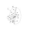
- FIG. 3 is a perspective view showing a state in which a rod is protruded in the impeller stop mechanism in the first embodiment of the water flow generator.
- the water flow generator 10 of this embodiment includes a power generation unit 11 and a structure 12.
- the power generation unit is provided in a pair on the left and right.
- the structural body 12 connects the left and right power generation units 11.
- the water flow generator 10 is moored to the seabed or an underwater structure or the like by a mooring cord 13 whose end is locked to the structure 12 and installed in seawater.
- Each power generation unit 11 includes an impeller 20 and a nacelle 30.
- the impeller 20 includes a hub 21 and a blade 22.
- the hub 21 is disposed at the center of the impeller 20.
- the hub 21 is formed in a so-called cannonball shape whose outer diameter gradually reduces toward the tip 21a (see FIG. 1).
- the hub 21 has an end face 21b opposite to the tip 21a.
- the end face 21 b is orthogonal to the rotation center axis C of the impeller 20 (hereinafter simply referred to as the axis C).
- the hub 21 is integrally provided with a cylindrical portion 21c at the outer peripheral portion of the end face 21b.
- the cylindrical portion 21c is formed in a cylindrical shape extending in the direction in which the axis C extends (hereinafter, simply referred to as the axis C direction) toward the opposite side to the tip 21a.
- a shaft 23 is integrally provided on the end face 21 b of the hub 21. The shaft 23 projects in the direction of the axis C toward the opposite side to the tip 21 a.
- a plurality of blades 22 are provided on the outer peripheral portion of the hub 21 at intervals in the circumferential direction.
- two blades 22 are provided.
- the two blades 22 are disposed at rotationally symmetrical positions.
- Each blade 22 has a proximal end 22 a integrally fixed to the cylindrical portion 21 c of the hub 21.
- Each blade 22 extends radially outward from the hub 21 toward the tip 22 b.
- the nacelle 30 includes a casing 31, a generator 32, and a main shaft 33.
- the casing 31 is formed in a cylindrical shape extending in the direction of the axis C.
- the casing 31 is provided with an impeller supporting portion 34 at its first end 31a.
- the impeller support 34 rotatably supports the impeller 20.
- a pair of outer bearings 35 is provided on the outer peripheral surface of the impeller support 34 at intervals in the direction of the axis C.
- the impeller 20 is rotatably supported by the impeller supporting portion 34 via the outer bearings 35.
- Each external bearing 35 is formed of, for example, a resin, and functions as a so-called slide bearing that rotatably supports the impeller 20 with the surrounding seawater as a lubricant.
- a partition wall 36 is provided in the casing 31.
- the partition wall 36 has a plane perpendicular to the axis C and facing the opposite side to the first end 31a (hereinafter, simply referred to as the second end) in the direction of the axis C.
- a sealed generator chamber 37 is formed on the second end side of the partition wall 36 in the direction of the axis C.
- the inside of the generator chamber 37 is an air atmosphere.
- the generator 32 is accommodated in the generator chamber 37.
- the generator 32 is provided with an input shaft 32a.
- the input shaft 32 a protrudes along the axis C toward the side closer to the partition wall 36.
- the generator 32 includes a rotor (not shown) integrally provided with the input shaft 32a, and a stator (not shown) facing the rotor.
- the generator 32 generates power when the rotor rotates with the input shaft 32a relative to the stator.
- the power generated by the generator 32 is supplied to the outside via a transmission line (not shown).
- a main shaft 33 is connected to an input shaft 32 a of the generator 32 via a speed increasing gear (not shown), a brake 40 and the like.
- the brake 40 is capable of reducing and stopping the rotational speed of the impeller 20.
- the brake 40 applies a braking force to the main shaft 33 when an abnormality occurs, such as exceeding a predetermined number of revolutions, or when performing regular maintenance, for example, by control of a controller (not shown) included in the water flow generator 10 Do.
- the main shaft 33 extends into the impeller support 34 through a shaft hole 36 h formed in the partition wall 36.
- a ring-shaped seal member 38 is provided between the main shaft 33 and the shaft hole 36 h. The seal member 38 prevents the water from entering the generator chamber 37 from around the main shaft 33.
- a coupling joint 50 is provided between the main shaft 33 and the shaft 23 provided on the hub 21 of the impeller 20.
- the main shaft 33 and the shaft 23 are connected via the coupling joint 50 in such a manner as to allow relative displacement in the axial direction, radial direction, and inclination direction.
- each power generation unit 11 includes an impeller rotation stop mechanism 60A.
- the impeller rotation stop mechanism 60A is provided on the nacelle (base) 30 or the structure (base) 12 (the nacelle 30 in the example of FIG. 1).
- the impeller rotation stop mechanism 60A includes a case 61 and a rod (rotation stop member) 62.
- the case 61 is cylindrical and fixed to the outer peripheral surface of the nacelle 30.
- the rod 62 is provided in the case 61.
- the rod 62 is slidable toward the impeller 20 by a drive mechanism (not shown) using spring force, oil pressure, air pressure or the like.
- the rod 62 is disposed in the rotation trajectory R of the blade 22 of the impeller 20, that is, at a position intersecting the rotation surface of the rotation trajectory R in a state of projecting from the case 61. That is, the rod 62 interferes with the blade 22 when the rod 62 enters the inside of the rotation trajectory R. The interference of the rod 62 inhibits the turning of the impeller 20.
- the operation of the impeller rotation stop mechanism 60A is controlled by a controller (not shown) provided in the water flow generator 10.
- a controller (not shown) provided in the water flow generator 10.
- a sensor (not shown) for measuring the rotational speed of the main shaft 33 and the rotational speed of the shaft 23 is provided.
- the controller when the difference between the rotational speeds of the main shaft 33 and the shaft 23 detected by the sensor exceeds a predetermined reference value, it is determined that a failure or the like has occurred in the coupling joint 50, and the impeller rotation stop mechanism Activate 60A.
- the rod 62 protrudes.
- the projection of the rod 62 causes the rod 62 to interfere with the blade 22 and causes the impeller 20 to stop turning.
- the impeller rotation stop mechanism 60A is operated based on the predetermined reference value of the rotation speed has been described. However, under what conditions the impeller rotation stop mechanism 60A is to be stopped may be set as appropriate.
- the rod 62 of the impeller rotation stopping mechanism 60A can be made to enter into the rotation trajectory R of the impeller 20. Therefore, the rod 62 can be made to interfere with the blade 22 of the impeller 20 to stop the rotation of the impeller 20. Thus, the impeller 20 can be reliably stopped even in an emergency or the like.
- FIG. 4 is a perspective view showing a state in which a rod is protruded in the impeller stop mechanism in the second embodiment of the water flow generator.
- each power generation unit 11 of the water flow generator 10 in this embodiment includes an impeller rotation stop mechanism 60B.
- the impeller rotation stop mechanism 60B is provided to the nacelle 30 or the structure 12 (the nacelle 30 in the example of FIG. 4).
- the impeller rotation stop mechanism 60 ⁇ / b> B includes a case 61 and a rod (rotation stop member) 63.
- the case 61 is formed in a tubular shape.
- the case 61 is fixed to the outer peripheral surface of the nacelle 30.
- the rod 63 is provided in the case 61.
- the rod 63 is slidable toward the impeller 20 by a drive mechanism (not shown) using spring force, oil pressure, air pressure or the like.
- the rod 63 is disposed in the rotation plane of the rotation trajectory R of the blade 22 of the impeller 20, that is, at a position intersecting the rotation trajectory R, in a state where the rod 63 protrudes from the case 61. Thereby, the rod 63 interferes with the blade 22 and the turning of the impeller 20 is inhibited.
- the rod 63 is formed with an acute angle portion 63 s at a position facing the side surface of the rotating blade 22.
- the acute angle portion 63s is formed in a wedge shape, a blade shape or the like in which the cross section is formed at an acute angle.
- the rod 63 of the acute angle portion 63 s is formed at least at the acute angle portion 63 s of a material harder than the blade 22.
- the acute angle portion 63s can be made of metal.
- the operation of the impeller rotation stopping mechanism 60B is controlled by a controller (not shown) provided to the water flow generator 10.
- the controller slides the rod 63 toward the impeller 20 side to project when the predetermined condition is satisfied.
- the rod 63 protrudes, the rod 63 interferes with the blade 22 of the impeller 20 which is turning.
- the acute angle portion 63 s is formed in the rod 63, so the acute angle portion 63 s bites into the side portion of the blade 22 or the blade 22 is cut.
- the acute angle portion 63 s bites into the blade 22, the acute angle portion 63 s is engaged with the blade 22 and the impeller 20 is stopped.
- the impeller 20 stops because the blade 22 can not rotate due to the ocean current.
- the rod 63 of the impeller rotation stopping mechanism 60B can be advanced into the rotation trajectory R of the impeller 20. Therefore, the rod 63 can interfere with the blade 22 of the impeller 20 to stop the rotation of the impeller 20. Furthermore, by advancing the rod 63 into the rotation trajectory R of the impeller 20, the acute angle portion 63s of the rod 63 can be bitten into the side portion of the blade 22 or the blade 22 can be cut by the acute angle portion 63s. . As a result, the rotation of the impeller 20 can be more reliably stopped.
- the impeller rotation stopping mechanisms 60A and 60B are installed on the outer peripheral surface of the nacelle 30.
- the impeller rotation stopping mechanisms 60A and 60B may be provided on the outer peripheral surface of the structure 12.
- the impeller rotation stopping mechanisms 60A and 60B may be accommodated inside the structure 12, and the rods 62 and 63 may be made to project from the structure 12 to the outside.
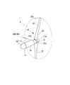
- FIG. 5 is a perspective view showing an impeller stop mechanism in the third embodiment of the water flow generator.
- FIG. 6 is a perspective view showing a state in which a cord-like body is developed. As shown to FIG. 5, FIG. 6, each electric power generation unit 11 of the water flow generator 10 in this embodiment is provided with the impeller rotation stop mechanism 60C.
- the impeller rotation stop mechanism 60C is provided in the nacelle 30 or the structure 12 (the structure 12 in the example of FIG. 5).
- the impeller rotation stop mechanism 60B includes a case 65 and a cord-like body (rotation stop member) 66.
- the case 65 has a hollow lid shape and is provided on the outer peripheral surface of the nacelle 30 so as to be openable and closable.
- the case 65 is controlled by a controller (not shown) provided in the water flow generator 10, and is opened when a predetermined condition is satisfied.
- the case 65 is disposed upstream of the ocean current with respect to the impeller 20.
- a plurality of cords 66 are provided in the case 65.
- the cord 66 is made of, for example, a metal wire, a cable having a predetermined breaking strength, a rope or the like.
- the cord 66 is usually accommodated in the case 65.
- FIG. 6 when the case 65 is opened, the cord 66 is expanded by the ocean current so as to extend toward the impeller 20.
- the cord 66 enters the rotational plane of the rotation trajectory R of the blade 22 of the impeller 20 and interferes with the blade 22 while extending from the case 65. Then, with the turning of the impeller 20, the cord 66 gradually entangles with the impeller 20, and the turning of the impeller 20 is inhibited.
- the rotation of the impeller 20 can be stopped by the cord-like body 66 being entangled in the impeller 20.
- the tip of the cord 66 may be provided with a parachute or the like that receives pressure from the ocean current. With such a configuration, the cord 66 is smoothly deployed toward the impeller 20 by receiving the pressure of the ocean current with a parachute or the like.
- another net such as a net, may be used.
- the present invention is not limited to the above-described embodiment, and includes the above-described embodiment with various modifications added thereto, without departing from the spirit of the present invention. That is, the specific shape, configuration, and the like described in the embodiment are merely examples, and can be changed as appropriate.
- the number of objects of the power generation unit 11 is not limited to two.
- the number of blades 22 of the impeller 20 is not limited to the above as long as it is a plurality of blades. Other than this, it is possible to adopt other composition suitably about composition of each part of water flow generator 10, etc.
- the present invention is applicable to a water flow generator.
- the water flow generator to which the present invention is applied can reliably stop the rotation of the impeller at low cost.
Abstract
水流発電機(10)は、ナセル(30)と、ナセル(30)に対して相対回転可能に設けられ、複数のブレード(22)を備えて水流によって回転する羽根車(20)と、ナセル(30)内に設けられて、羽根車(20)から伝達される回転力によって発電する発電機と、ナセル(30)に設けられ、羽根車(20)の回転軌跡内に進入可能とされたロッド(62)を備え、羽根車(20)の回転を停止させる羽根車回転停止機構(60A)と、を備える。
Description
本発明は、水流発電機に関する。
本願は、2015年2月17日に、日本に出願された特願2015-028496号に基づき優先権を主張し、その内容をここに援用する。
本願は、2015年2月17日に、日本に出願された特願2015-028496号に基づき優先権を主張し、その内容をここに援用する。
特許文献1に開示されているように、海や河川等における海流や水流を利用して発電を行う水流発電機は、羽根車と、発電機と、を備えている。羽根車は、外周側に向かって延びる複数のブレード(羽根)を有している。発電機は、回転軸の端部が羽根車に連結され、海流や水流によって回転する羽根車とともに回転軸が回転することで、発電を行う。
このような水中発電機は、メンテナンス時等に羽根車の回転を停止させるため、ブレーキ機構を備えている。
上述した水流発電機のブレーキ装置は、油圧や電気を用いて駆動する場合が多い。そのため、ブレーキ装置は、水中ではなく空気雰囲気である発電機室の中に通常配置されている。
羽根車には、海流に応じたトルクが、常に発生している。そのため、例えば、羽根車と発電機室との間の伝達系に、伝達不良等の不具合が生じた場合、ブレーキ装置によって羽根車の回転を停止できなくなることが想定される。
水圧の高い深海に水流発電機が設置される場合、通常のブレーキ装置を設置すると、水密構造等が複雑化してコストが増加してしまう。そのため、上記水中発電機においては、緊急時等に備え、ブレーキ機構とは別に、羽根車の回転を強制的に停止させる装置を低コストで設けることが望まれている。
この発明は、低コストで羽根車の回転を確実に停止させることができる水流発電機を提供することを目的とする。
羽根車には、海流に応じたトルクが、常に発生している。そのため、例えば、羽根車と発電機室との間の伝達系に、伝達不良等の不具合が生じた場合、ブレーキ装置によって羽根車の回転を停止できなくなることが想定される。
水圧の高い深海に水流発電機が設置される場合、通常のブレーキ装置を設置すると、水密構造等が複雑化してコストが増加してしまう。そのため、上記水中発電機においては、緊急時等に備え、ブレーキ機構とは別に、羽根車の回転を強制的に停止させる装置を低コストで設けることが望まれている。
この発明は、低コストで羽根車の回転を確実に停止させることができる水流発電機を提供することを目的とする。
この発明の第一態様によれば、水流発電機は、基体と、前記基体に対して相対回転可能に設けられ、複数の羽根で水流を捉えて回転する羽根車と、を備えている。水流発電機は、前記基体の内部に設けられて、前記羽根車から伝達される回転エネルギーを電気エネルギーに変換して出力する発電機を更に備えている。水流発電機は、前記基体に設けられ、前記羽根車の回転軌跡の外側から前記回転軌跡の内側へ進入可能な回転停止部材を有する羽根車回転停止機構、を更に備えている。
このように構成することで、羽根車回転停止機構の回転停止部材を羽根車の回転軌跡の内側に進入させることができる。そのため、回転停止部材を羽根車の羽根に干渉させることができる。これにより、羽根車の回転を停止させることができる。
このように構成することで、羽根車回転停止機構の回転停止部材を羽根車の回転軌跡の内側に進入させることができる。そのため、回転停止部材を羽根車の羽根に干渉させることができる。これにより、羽根車の回転を停止させることができる。
この発明の第二態様によれば、水流発電機は、第一態様における前記回転停止部材が、その長手方向にスライド可能なロッドであってもよい。
このように構成することで、ロッドを羽根車の回転軌跡の内側に進入させてロッドを羽根車の羽根と干渉させることができる。そのため、羽根車の回転を停止させることができる。
このように構成することで、ロッドを羽根車の回転軌跡の内側に進入させてロッドを羽根車の羽根と干渉させることができる。そのため、羽根車の回転を停止させることができる。
この発明の第三態様によれば、水流発電機は、第二態様における前記ロッドが、少なくとも前記回転軌跡と交差する部位に、前記羽根車の回転方向と反対方向を向く断面が鋭角な鋭角部を有しているようにしてもよい。
このように構成することで、羽根車の回転軌跡に配置されたロッドの鋭角部が羽根に衝突する際に、羽根車の羽根に食い込ませたり、羽根を切断したりすることができる。その結果、羽根車の回転をより確実に停止させることができる。
このように構成することで、羽根車の回転軌跡に配置されたロッドの鋭角部が羽根に衝突する際に、羽根車の羽根に食い込ませたり、羽根を切断したりすることができる。その結果、羽根車の回転をより確実に停止させることができる。
この発明の第四態様によれば、水流発電機は、第一態様において、前記回転停止部材が、前記回転軌跡の内側に向けて展開可能な索状体であるようにしてもよい。
このように構成することで、回転軌跡の内側に向けて展開された索状体が羽根車に絡みつき、羽根車の回転を停止させることができる。
このように構成することで、回転軌跡の内側に向けて展開された索状体が羽根車に絡みつき、羽根車の回転を停止させることができる。
上記水流発電機によれば、低コストで羽根車の回転を確実に停止させることができる。
(第一実施形態)
図1は、この実施形態における水流発電機を示す斜視図である。図2は、上記水流発電機の実施形態における羽根車とナセルとの連結部分の構成を示す断面図である。図3は、上記水流発電機の第一実施形態における羽根車停止機構において、ロッドを突出させた状態を示す斜視図である。
図1に示すように、この実施形態の水流発電機10は、発電ユニット11と構造体12とを備えている。
発電ユニットは、左右一対で設けられている。
構造体12は、左右の発電ユニット11を連結する。
水流発電機10は、構造体12に端部を係止させた係留索13により、海底や水中構造物等に係留されて海水中に設置される。
図1は、この実施形態における水流発電機を示す斜視図である。図2は、上記水流発電機の実施形態における羽根車とナセルとの連結部分の構成を示す断面図である。図3は、上記水流発電機の第一実施形態における羽根車停止機構において、ロッドを突出させた状態を示す斜視図である。
図1に示すように、この実施形態の水流発電機10は、発電ユニット11と構造体12とを備えている。
発電ユニットは、左右一対で設けられている。
構造体12は、左右の発電ユニット11を連結する。
水流発電機10は、構造体12に端部を係止させた係留索13により、海底や水中構造物等に係留されて海水中に設置される。
各発電ユニット11は、羽根車20と、ナセル30と、を備えている。
羽根車20は、ハブ21と、ブレード22と、を備えている。
羽根車20は、ハブ21と、ブレード22と、を備えている。
図1、図2に示すように、ハブ21は、羽根車20の中央部に配置されている。ハブ21は、先端21a(図1参照)に向かって外径が漸次縮小するいわゆる砲弾状に形成されている。ハブ21は、先端21aと反対側に、端面21bを有している。端面21bは、羽根車20の回転中心軸C(以下、単に軸線Cと称する)に直交する。ハブ21は、その端面21bの外周部に、筒状部21cが一体に設けられている。筒状部21cは、軸線Cの延びる方向(以下、単に軸線C方向と称する)で先端21aと反対側に向かって延びる円筒状に形成されている。ハブ21の端面21bには、シャフト23が一体に設けられている。このシャフト23は、軸線C方向で先端21aとは反対側に向けて突出している。
ブレード22は、ハブ21の外周部に、周方向に間隔をあけて複数本設けられている。
この実施形態においては、2本のブレード22が設けられている。これら2本のブレード22は、それぞれ回転対称な位置に配されている。各ブレード22は、基端部22aがハブ21の筒状部21cに一体に固定されている。各ブレード22は、先端部22bに向かってハブ21から放射方向外側に延びている。
この実施形態においては、2本のブレード22が設けられている。これら2本のブレード22は、それぞれ回転対称な位置に配されている。各ブレード22は、基端部22aがハブ21の筒状部21cに一体に固定されている。各ブレード22は、先端部22bに向かってハブ21から放射方向外側に延びている。
ナセル30は、ケーシング31と、発電機32と、メインシャフト33と、を備えている。
ケーシング31は、軸線C方向に延びる円筒状に形成されている。このケーシング31は、その第一端部31aに羽根車支持部34が設けられている。羽根車支持部34は、羽根車20を回転自在に支持する。羽根車支持部34の外周面には、軸線C方向に間隔をあけて、一対の外部軸受35が設けられている。羽根車20は、これら外部軸受35を介して、羽根車支持部34に回転自在に支持されている。各外部軸受35は、例えば、樹脂で形成され、周囲の海水を潤滑剤として羽根車20を回転自在に支持する、いわゆる滑り軸受として機能する。
ケーシング31は、軸線C方向に延びる円筒状に形成されている。このケーシング31は、その第一端部31aに羽根車支持部34が設けられている。羽根車支持部34は、羽根車20を回転自在に支持する。羽根車支持部34の外周面には、軸線C方向に間隔をあけて、一対の外部軸受35が設けられている。羽根車20は、これら外部軸受35を介して、羽根車支持部34に回転自在に支持されている。各外部軸受35は、例えば、樹脂で形成され、周囲の海水を潤滑剤として羽根車20を回転自在に支持する、いわゆる滑り軸受として機能する。
ケーシング31内には、隔壁36が設けられている。この隔壁36は、軸線Cに直交し、且つ、軸線C方向で第一端部31aとは反対側(以下、単に第二端部側と称する)を向く平面を有している。ケーシング31内には、軸線C方向で隔壁36よりも第二端部側に、密閉された発電機室37が形成されている。この発電機室37内は、空気雰囲気とされている。発電機室37には、発電機32が収容されている。
発電機32は、入力軸32aを備えている。入力軸32aは、軸線Cに沿って隔壁36に近い側に突出する。この発電機32は、入力軸32aと一体に設けられたロータ(図示無し)と、ロータに対向するステータ(図示無し)と、を備えている。発電機32は、入力軸32aとともにロータがステータに対して相対的に回転することで発電する。この発電機32によって発電された電力は、送電線(図示無し)を介して外部に供給される。この発電機32の入力軸32aには、増速器(図示無し)、ブレーキ40等を介してメインシャフト33が連結されている。
ブレーキ40は、羽根車20の回転速度を低減、および、停止させることが可能となっている。ブレーキ40は、水流発電機10が備えるコントローラ(図示無し)の制御により、例えば所定の回転数を超える等、異常が発生した場合や、定期メンテナンスを行うときに、メインシャフト33に制動力を付与する。
メインシャフト33は、隔壁36に形成されたシャフト孔36hを通じて羽根車支持部34内に延びている。これらメインシャフト33とシャフト孔36hとの間には、リング状のシール部材38が設けられている。
シール部材38は、メインシャフト33周りから発電機室37内への浸水を防止している。
シール部材38は、メインシャフト33周りから発電機室37内への浸水を防止している。
メインシャフト33と、羽根車20のハブ21に設けられたシャフト23との間には、カップリング継手50が設けられている。このカップリング継手50を介し、メインシャフト33とシャフト23とが、軸方向、径方向、傾斜方向の相対変位が可能な状態で接続されている。
図1に示すように、各発電ユニット11は、羽根車回転停止機構60Aを備えている。
羽根車回転停止機構60Aは、ナセル(基体)30または構造体(基体)12(図1の例ではナセル30)に設けられている。羽根車回転停止機構60Aは、ケース61と、ロッド(回転停止部材)62と、を備える。
羽根車回転停止機構60Aは、ナセル(基体)30または構造体(基体)12(図1の例ではナセル30)に設けられている。羽根車回転停止機構60Aは、ケース61と、ロッド(回転停止部材)62と、を備える。
ケース61は、筒状で、ナセル30の外周面に固定されている。
ロッド62は、ケース61内に設けられている。ロッド62は、バネ力、油圧、空圧等を用いた駆動機構(図示無し)により羽根車20側に向けてスライド変位可能とされている。
図3に示すように、ロッド62は、ケース61から突出した状態で、羽根車20のブレード22の回転軌跡R内、すなわち回転軌跡Rの回転面と交差する位置に配置される。つまり、ロッド62が回転軌跡Rの内側に進入することで、ロッド62がブレード22に干渉する。このロッド62の干渉により、羽根車20の旋回が阻害されることとなる。
ロッド62は、ケース61内に設けられている。ロッド62は、バネ力、油圧、空圧等を用いた駆動機構(図示無し)により羽根車20側に向けてスライド変位可能とされている。
図3に示すように、ロッド62は、ケース61から突出した状態で、羽根車20のブレード22の回転軌跡R内、すなわち回転軌跡Rの回転面と交差する位置に配置される。つまり、ロッド62が回転軌跡Rの内側に進入することで、ロッド62がブレード22に干渉する。このロッド62の干渉により、羽根車20の旋回が阻害されることとなる。
羽根車回転停止機構60Aの作動は、水流発電機10に備えられたコントローラ(図示無し)により制御される。例えば、ナセル30内に、メインシャフト33の回転数と、シャフト23の回転数とを計測するセンサ(図示無し)を設けておく。コントローラーでは、センサで検出するメインシャフト33とシャフト23との回転数の差が、予め定めた基準値を超えた場合、カップリング継手50に故障等が発生したと判断し、羽根車回転停止機構60Aを作動させる。これにより、ロッド62が突出する。このロッド62の突出により、ロッド62がブレード22に干渉して羽根車20が旋回停止する。ここでは、予め定めた回転数の基準値に基づいて羽根車回転停止機構60Aを作動させる場合について説明した。しかし、どのような条件で羽根車回転停止機構60Aを停止させるかは適宜設定すればよい。
したがって、上述した第一実施形態の水流発電機によれば、羽根車回転停止機構60Aのロッド62を羽根車20の回転軌跡R内に進入させることができる。そのため、ロッド62を羽根車20のブレード22に干渉させて、羽根車20の回転を停止させることができる。これにより、緊急時等においても、羽根車20を確実に停止させることができる。
(第二実施形態)
次に、この発明にかかる水流発電機の第二実施形態について説明する。以下に説明する第二実施形態においては、第一実施形態と羽根車回転停止機構60Bの構成のみが異なるので、第一実施形態と同一部分に同一符号を付して説明するとともに、重複説明を省略する。
次に、この発明にかかる水流発電機の第二実施形態について説明する。以下に説明する第二実施形態においては、第一実施形態と羽根車回転停止機構60Bの構成のみが異なるので、第一実施形態と同一部分に同一符号を付して説明するとともに、重複説明を省略する。
図4は、上記水流発電機の第二実施形態における羽根車停止機構において、ロッドを突出させた状態を示す斜視図である。
図4に示すように、この実施形態における水流発電機10の各発電ユニット11は、羽根車回転停止機構60Bを備えている。この羽根車回転停止機構60Bは、ナセル30または構造体12(図4の例ではナセル30)に設けられている。羽根車回転停止機構60Bは、ケース61と、ロッド(回転停止部材)63と、を備える。
図4に示すように、この実施形態における水流発電機10の各発電ユニット11は、羽根車回転停止機構60Bを備えている。この羽根車回転停止機構60Bは、ナセル30または構造体12(図4の例ではナセル30)に設けられている。羽根車回転停止機構60Bは、ケース61と、ロッド(回転停止部材)63と、を備える。
ケース61は、筒状に形成されている。ケース61は、ナセル30の外周面に固定されている。
ロッド63は、ケース61内に設けられている。ロッド63は、バネ力、油圧、空圧等を用いた駆動機構(図示無し)により羽根車20側に向けてスライド変位可能とされている。ロッド63は、ケース61から突出した状態で、羽根車20のブレード22の回転軌跡Rの回転面内、すなわち回転軌跡Rと交差する位置に配置される。これにより、ロッド63がブレード22に干渉して羽根車20の旋回が阻害される。
ロッド63は、ケース61内に設けられている。ロッド63は、バネ力、油圧、空圧等を用いた駆動機構(図示無し)により羽根車20側に向けてスライド変位可能とされている。ロッド63は、ケース61から突出した状態で、羽根車20のブレード22の回転軌跡Rの回転面内、すなわち回転軌跡Rと交差する位置に配置される。これにより、ロッド63がブレード22に干渉して羽根車20の旋回が阻害される。
このロッド63には、旋回するブレード22の側面に対向する位置に鋭角部63sが形成されている。この鋭角部63sは、その断面が鋭角に形成されたクサビ状、刃物状等に形成されている。鋭角部63sのロッド63は、少なくともその鋭角部63sが、ブレード22よりも硬度の高い材料で形成されている。例えば、ブレード22が強化繊維プラスチック製の場合、鋭角部63sは金属製とすることができる。
羽根車回転停止機構60Bの作動は、水流発電機10に設けられたコントローラー(図示無し)により制御される。このコントローラーは、所定の条件を満足したときに、ロッド63を羽根車20側に向けてスライド変位させて突出させる。ロッド63が突出すると、旋回中の羽根車20のブレード22に対し、ロッド63が干渉する。ロッド63には、鋭角部63sが形成されているので、鋭角部63sがブレード22の側部に食い込んだり、ブレード22が切断されたりする。ブレード22に鋭角部63sが食い込んだ場合には、ブレード22に対して鋭角部63sが係止されて羽根車20が停止する。ブレード22が切断された場合には、ブレード22が海流を受けて回転することができなくなるため羽根車20が停止する。
したがって、上述した第二実施形態の水流発電機によれば、羽根車回転停止機構60Bのロッド63を羽根車20の回転軌跡R内に進入させることができる。そのため、ロッド63が羽根車20のブレード22と干渉して羽根車20の回転を停止させることができる。
さらに、ロッド63を羽根車20の回転軌跡R内に進入させることで、ロッド63の鋭角部63sをブレード22の側部に食い込ませたり、鋭角部63sによりブレード22を切断したりすることができる。その結果、羽根車20の回転をより確実に停止させることができる。
さらに、ロッド63を羽根車20の回転軌跡R内に進入させることで、ロッド63の鋭角部63sをブレード22の側部に食い込ませたり、鋭角部63sによりブレード22を切断したりすることができる。その結果、羽根車20の回転をより確実に停止させることができる。
(第一、第二実施形態の変形例)
ここで、上述した第一、第二実施形態においては、羽根車回転停止機構60A,60Bをナセル30の外周面に設置するようにした。しかし、この構成に限られるものではない。羽根車回転停止機構60A,60Bは、構造体12の外周面に設けるようにしてもよい。羽根車回転停止機構60A,60Bは、構造体12の内部に収容し、ロッド62,63を構造体12から外部に突出させるようにしてもよい。
ここで、上述した第一、第二実施形態においては、羽根車回転停止機構60A,60Bをナセル30の外周面に設置するようにした。しかし、この構成に限られるものではない。羽根車回転停止機構60A,60Bは、構造体12の外周面に設けるようにしてもよい。羽根車回転停止機構60A,60Bは、構造体12の内部に収容し、ロッド62,63を構造体12から外部に突出させるようにしてもよい。
(第三実施形態)
次に、この発明にかかる水流発電機の第三実施形態について説明する。この第三実施形態においては、第一、第二実施形態と羽根車回転停止機構60Cの構成のみが異なるので、第一、第二実施形態と同一部分に同一符号を付して説明するとともに、重複説明を省略する。
次に、この発明にかかる水流発電機の第三実施形態について説明する。この第三実施形態においては、第一、第二実施形態と羽根車回転停止機構60Cの構成のみが異なるので、第一、第二実施形態と同一部分に同一符号を付して説明するとともに、重複説明を省略する。
図5は、水流発電機の第三実施形態における羽根車停止機構を示す斜視図である。図6は、索状体を展開させた状態を示す斜視図である。
図5、図6に示すように、この実施形態における水流発電機10の各発電ユニット11は、羽根車回転停止機構60Cを備えている。
図5、図6に示すように、この実施形態における水流発電機10の各発電ユニット11は、羽根車回転停止機構60Cを備えている。
羽根車回転停止機構60Cは、ナセル30または構造体12(図5の例では構造体12)に設けられている。羽根車回転停止機構60Bは、ケース65と、索状体(回転停止部材)66と、を備えている。
ケース65は、中空の蓋状で、ナセル30の外周面に開閉可能に設けられている。このケース65は、水流発電機10に設けられたコントローラ(図示無し)により制御され、所定の条件を満足した場合に開くようになっている。このケース65は、羽根車20に対して海流の上流側に配されている。
索状体66は、複数本がケース65内に設けられている。索状体66は、例えば金属ワイヤーや、その他所定の破断強度を有したケーブル、ロープ等からなる。索状体66は、通常時においては、ケース65内に収容されている。図6に示すように、索状体66は、ケース65が開くと、海流によって、羽根車20側に向けて延びるように展開される。索状体66は、ケース65から延びた状態で、羽根車20のブレード22の回転軌跡Rの回転面内に進入してブレード22に干渉する。すると、羽根車20の旋回にともなって、索状体66が羽根車20に徐々に絡みつき、羽根車20の旋回が阻害される。
したがって、上述した第三実施形態の水流発電機によれば、索状体66が羽根車20に絡みつくことによって、羽根車20の回転を停止させることができる。
(第3実施形態の変形例)
第3実施形態においては、索状体66の先端部に、海流による圧力を受けるパラシュート等を備えてもよい。このような構成とすることで、パラシュート等で海流の圧力を受けることによって、索状体66は、羽根車20に向けてスムーズに展開される。
索状体66に代えて、網状のネット等、他のものを用いてもよい。
第3実施形態においては、索状体66の先端部に、海流による圧力を受けるパラシュート等を備えてもよい。このような構成とすることで、パラシュート等で海流の圧力を受けることによって、索状体66は、羽根車20に向けてスムーズに展開される。
索状体66に代えて、網状のネット等、他のものを用いてもよい。
(その他の変形例)
この発明は、上述した実施形態に限定されるものではなく、この発明の趣旨を逸脱しない範囲において、上述した実施形態に種々の変更を加えたものを含む。すなわち、実施形態で挙げた具体的な形状や構成等は一例にすぎず、適宜変更が可能である。
上述した各実施形態、および、各変形例においては、水流発電機10が深海に設置される場合について説明したが、深海に限られるものではない。
さらに、上述した各実施形態、および、各変形例においては、発電ユニット11が2つ設けられている場合について説明したが、発電ユニット11の個数は2つに限られない。
さらに、羽根車20のブレード22の枚数も複数枚であれば、上述した枚数に限られない。
これ以外にも、水流発電機10の各部の構成等については、適宜他の構成を採用することが可能である。
この発明は、水流発電機に適用できる。この発明を適用した水流発電機は、低コストで羽根車の回転を確実に停止させることが可能となる。
10 水流発電機
11 発電ユニット
12 構造体(基体)
13 係留索
20 羽根車
21 ハブ
21a 先端
21b 端面
21c 筒状部
22 ブレード
22a 基端部
22b 先端部
23 シャフト
30 ナセル(基体)
31 ケーシング
31a 第一端部
32 発電機
32a 入力軸
33 メインシャフト
34 羽根車支持部
35 外部軸受
36 隔壁
36h シャフト孔
37 発電機室
38 シール部材
40 ブレーキ
50 カップリング継手
60A,60B,60C 羽根車回転停止機構
61 ケース
62,63 ロッド(回転停止部材)
63s 鋭角部
65 ケース
66 索状体(回転停止部材)
11 発電ユニット
12 構造体(基体)
13 係留索
20 羽根車
21 ハブ
21a 先端
21b 端面
21c 筒状部
22 ブレード
22a 基端部
22b 先端部
23 シャフト
30 ナセル(基体)
31 ケーシング
31a 第一端部
32 発電機
32a 入力軸
33 メインシャフト
34 羽根車支持部
35 外部軸受
36 隔壁
36h シャフト孔
37 発電機室
38 シール部材
40 ブレーキ
50 カップリング継手
60A,60B,60C 羽根車回転停止機構
61 ケース
62,63 ロッド(回転停止部材)
63s 鋭角部
65 ケース
66 索状体(回転停止部材)
Claims (4)
- 基体と、
前記基体に対して相対回転可能に設けられ、複数の羽根で水流を捉えて回転する羽根車と、
前記基体の内部に設けられて、前記羽根車から伝達される回転エネルギーを電気エネルギーに変換して出力する発電機と、
前記基体に設けられ、前記羽根車の回転軌跡の外側から前記回転軌跡の内側に進入可能な回転停止部材を有する羽根車回転停止機構と、
を備える水流発電機。 - 前記回転停止部材は、
その長手方向にスライド可能なロッドである請求項1に記載の水流発電機。 - 前記ロッドは、
少なくとも前記回転軌跡と交差する部位に、前記羽根車の回転方向と反対方向を向く断面が鋭角な鋭角部を有している請求項2に記載の水流発電機。 - 前記回転停止部材は、
前記回転軌跡の内側に向けて展開可能な索状体である請求項1に記載の水流発電機。
Priority Applications (2)
| Application Number | Priority Date | Filing Date | Title |
|---|---|---|---|
| CN201580076077.XA CN107208600B (zh) | 2015-02-17 | 2015-10-23 | 水流发电机 |
| US15/551,119 US10215150B2 (en) | 2015-02-17 | 2015-10-23 | Water flow power generator |
Applications Claiming Priority (2)
| Application Number | Priority Date | Filing Date | Title |
|---|---|---|---|
| JP2015028496A JP6207092B2 (ja) | 2015-02-17 | 2015-02-17 | 水流発電機 |
| JP2015-028496 | 2015-02-17 |
Publications (1)
| Publication Number | Publication Date |
|---|---|
| WO2016132600A1 true WO2016132600A1 (ja) | 2016-08-25 |
Family
ID=56688880
Family Applications (1)
| Application Number | Title | Priority Date | Filing Date |
|---|---|---|---|
| PCT/JP2015/079951 WO2016132600A1 (ja) | 2015-02-17 | 2015-10-23 | 水流発電機 |
Country Status (4)
| Country | Link |
|---|---|
| US (1) | US10215150B2 (ja) |
| JP (1) | JP6207092B2 (ja) |
| CN (1) | CN107208600B (ja) |
| WO (1) | WO2016132600A1 (ja) |
Families Citing this family (3)
| Publication number | Priority date | Publication date | Assignee | Title |
|---|---|---|---|---|
| JP6358927B2 (ja) * | 2014-10-29 | 2018-07-18 | 三菱重工業株式会社 | 海中浮遊式海流発電装置 |
| GB2606488B (en) * | 2021-05-06 | 2024-02-21 | Achelous Energy Ltd | Systems and devices for a floating renewable power station |
| CN114368845A (zh) * | 2021-12-09 | 2022-04-19 | 徐州市正联机电设备有限公司 | 一种用于生态修复增氧机防止叶轮打滑的固定装置 |
Citations (5)
| Publication number | Priority date | Publication date | Assignee | Title |
|---|---|---|---|---|
| JPH05180140A (ja) * | 1991-12-27 | 1993-07-20 | Fuji Electric Co Ltd | 水車の非常用ガイドベーン閉鎖装置 |
| JP2005069055A (ja) * | 2003-08-21 | 2005-03-17 | Toshiba Plant Systems & Services Corp | 水力発電装置 |
| JP2010531956A (ja) * | 2007-06-29 | 2010-09-30 | アクアンティス,エル.エル.シー. | マルチポイント係留及び安定化システム、及び流れを用いた水中用タービンのための制御方法 |
| JP2011112055A (ja) * | 2009-11-26 | 2011-06-09 | Siemens Ag | 一体化されたロータロックを備えた風車のためのブレーキシステム、発電機、及び風車 |
| JP2014532836A (ja) * | 2011-11-08 | 2014-12-08 | ヴォッベン プロパティーズ ゲーエムベーハーWobben Properties Gmbh | 水力発電装置用のタービン並びに水力発電装置 |
Family Cites Families (13)
| Publication number | Priority date | Publication date | Assignee | Title |
|---|---|---|---|---|
| US3584984A (en) * | 1968-02-03 | 1971-06-15 | Zaklady Mechanizzne Tarrow | Rotary device |
| US5125131A (en) * | 1991-01-14 | 1992-06-30 | Hughes Aircraft Company | Hinge locking mechanism with disengage action |
| DE4229989A1 (de) * | 1992-09-08 | 1994-03-10 | Festo Kg | Dreh-Linear-Einheit |
| US5947204A (en) * | 1997-09-23 | 1999-09-07 | Dresser Industries, Inc. | Production fluid control device and method for oil and/or gas wells |
| DE102004013624A1 (de) * | 2004-03-19 | 2005-10-06 | Sb Contractor A/S | Verfahren zum Betreiben einer Windenergieanlage und Windenergieanlage |
| CA2760192A1 (en) | 2009-04-28 | 2010-11-04 | Atlantis Resources Corporation Pte Limited | Underwater power generator |
| EP2597306B1 (en) * | 2011-09-22 | 2015-08-26 | Mitsubishi Heavy Industries, Ltd. | Regenerative energy power generation device and rotor locking method therefor |
| US9470208B2 (en) * | 2012-07-05 | 2016-10-18 | General Electric Company | Wind turbine and locking method |
| US20140010656A1 (en) * | 2012-07-05 | 2014-01-09 | Jacob Johannes Nies | Fixation device |
| EP2690284B1 (en) * | 2012-07-23 | 2015-08-26 | Siemens Aktiengesellschaft | Wind turbine generator and maintenance of its main bearing |
| JP2015025365A (ja) * | 2013-07-24 | 2015-02-05 | 小林 修 | 水流圧力による傾斜型回転動力発生装置 |
| JP6248017B2 (ja) * | 2014-09-12 | 2017-12-13 | 三菱重工業株式会社 | 海流発電装置の起動方法及び起動制御装置 |
| JP6358927B2 (ja) * | 2014-10-29 | 2018-07-18 | 三菱重工業株式会社 | 海中浮遊式海流発電装置 |
-
2015
- 2015-02-17 JP JP2015028496A patent/JP6207092B2/ja active Active
- 2015-10-23 CN CN201580076077.XA patent/CN107208600B/zh active Active
- 2015-10-23 US US15/551,119 patent/US10215150B2/en active Active
- 2015-10-23 WO PCT/JP2015/079951 patent/WO2016132600A1/ja active Application Filing
Patent Citations (5)
| Publication number | Priority date | Publication date | Assignee | Title |
|---|---|---|---|---|
| JPH05180140A (ja) * | 1991-12-27 | 1993-07-20 | Fuji Electric Co Ltd | 水車の非常用ガイドベーン閉鎖装置 |
| JP2005069055A (ja) * | 2003-08-21 | 2005-03-17 | Toshiba Plant Systems & Services Corp | 水力発電装置 |
| JP2010531956A (ja) * | 2007-06-29 | 2010-09-30 | アクアンティス,エル.エル.シー. | マルチポイント係留及び安定化システム、及び流れを用いた水中用タービンのための制御方法 |
| JP2011112055A (ja) * | 2009-11-26 | 2011-06-09 | Siemens Ag | 一体化されたロータロックを備えた風車のためのブレーキシステム、発電機、及び風車 |
| JP2014532836A (ja) * | 2011-11-08 | 2014-12-08 | ヴォッベン プロパティーズ ゲーエムベーハーWobben Properties Gmbh | 水力発電装置用のタービン並びに水力発電装置 |
Also Published As
| Publication number | Publication date |
|---|---|
| US10215150B2 (en) | 2019-02-26 |
| CN107208600A (zh) | 2017-09-26 |
| JP6207092B2 (ja) | 2017-10-04 |
| CN107208600B (zh) | 2019-06-21 |
| JP2016151206A (ja) | 2016-08-22 |
| US20180038339A1 (en) | 2018-02-08 |
Similar Documents
| Publication | Publication Date | Title |
|---|---|---|
| WO2016132600A1 (ja) | 水流発電機 | |
| JP5379851B2 (ja) | タービン翼ピッチ角を制御するための装置 | |
| JP5626256B2 (ja) | 発電装置 | |
| JP5150751B2 (ja) | 流体力発電装置 | |
| JP6363123B2 (ja) | 風車並びにそのヨー制御装置及び運転制御方法 | |
| JP2011141015A (ja) | シール装置及びこれを備えた流体機械 | |
| CN102046925B (zh) | 用于控制飞行器涡轮轴发动机中的螺旋桨叶片螺距的简化系统 | |
| JP5626257B2 (ja) | 発電装置 | |
| JP6692998B2 (ja) | 蒸気タービン過速度保護システム及び蒸気タービン | |
| KR101978016B1 (ko) | 전기장 유체를 이용한 자동 접이식 풍력발전 블레이드 장치 | |
| JP5390261B2 (ja) | 水平軸風車 | |
| JP2015500423A (ja) | 風力発電プラントのローターブレードを固定するための組立体 | |
| JP2011180141A (ja) | 電気機械式装置および電気機械式装置の被駆動構成要素にかかる負荷を求める方法 | |
| US20230110951A1 (en) | Yaw braking assembly of a wind turbine | |
| JP5752527B2 (ja) | 水流発電システム | |
| JP5894890B2 (ja) | 風力発電システム、風力発電システムの組み立て方法、または風力発電システムの点検方法 | |
| KR101390843B1 (ko) | 선박용 추진장치 및 이를 갖춘 선박 | |
| JP5976414B2 (ja) | 水流発電装置 | |
| JP6272147B2 (ja) | 風力発電装置 | |
| JP2016151249A5 (ja) | ||
| JPS6354144B2 (ja) | ||
| KR101555922B1 (ko) | 에어 브레이크를 구비하는 풍력 발전기 | |
| CA3028133A1 (en) | Fluid machine and power generation device | |
| JP6794929B2 (ja) | 風力発電装置 | |
| KR101158967B1 (ko) | 풍력 발전기용 슬립링 연결장치 |
Legal Events
| Date | Code | Title | Description |
|---|---|---|---|
| 121 | Ep: the epo has been informed by wipo that ep was designated in this application |
Ref document number: 15882701 Country of ref document: EP Kind code of ref document: A1 |
|
| WWE | Wipo information: entry into national phase |
Ref document number: 15551119 Country of ref document: US |
|
| NENP | Non-entry into the national phase |
Ref country code: DE |
|
| 122 | Ep: pct application non-entry in european phase |
Ref document number: 15882701 Country of ref document: EP Kind code of ref document: A1 |