WO2016129256A1 - 送信方法、送信装置、受信方法、受信装置 - Google Patents
送信方法、送信装置、受信方法、受信装置 Download PDFInfo
- Publication number
- WO2016129256A1 WO2016129256A1 PCT/JP2016/000574 JP2016000574W WO2016129256A1 WO 2016129256 A1 WO2016129256 A1 WO 2016129256A1 JP 2016000574 W JP2016000574 W JP 2016000574W WO 2016129256 A1 WO2016129256 A1 WO 2016129256A1
- Authority
- WO
- WIPO (PCT)
- Prior art keywords
- packet
- information
- decoding
- data
- unit
- Prior art date
Links
Images


Classifications
-
- H—ELECTRICITY
- H04—ELECTRIC COMMUNICATION TECHNIQUE
- H04L—TRANSMISSION OF DIGITAL INFORMATION, e.g. TELEGRAPHIC COMMUNICATION
- H04L1/00—Arrangements for detecting or preventing errors in the information received
- H04L1/004—Arrangements for detecting or preventing errors in the information received by using forward error control
- H04L1/0045—Arrangements at the receiver end
- H04L1/0054—Maximum-likelihood or sequential decoding, e.g. Viterbi, Fano, ZJ algorithms
-
- H—ELECTRICITY
- H03—ELECTRONIC CIRCUITRY
- H03M—CODING; DECODING; CODE CONVERSION IN GENERAL
- H03M13/00—Coding, decoding or code conversion, for error detection or error correction; Coding theory basic assumptions; Coding bounds; Error probability evaluation methods; Channel models; Simulation or testing of codes
- H03M13/03—Error detection or forward error correction by redundancy in data representation, i.e. code words containing more digits than the source words
- H03M13/05—Error detection or forward error correction by redundancy in data representation, i.e. code words containing more digits than the source words using block codes, i.e. a predetermined number of check bits joined to a predetermined number of information bits
- H03M13/11—Error detection or forward error correction by redundancy in data representation, i.e. code words containing more digits than the source words using block codes, i.e. a predetermined number of check bits joined to a predetermined number of information bits using multiple parity bits
- H03M13/1102—Codes on graphs and decoding on graphs, e.g. low-density parity check [LDPC] codes
- H03M13/1105—Decoding
- H03M13/1111—Soft-decision decoding, e.g. by means of message passing or belief propagation algorithms
- H03M13/1125—Soft-decision decoding, e.g. by means of message passing or belief propagation algorithms using different domains for check node and bit node processing, wherein the different domains include probabilities, likelihood ratios, likelihood differences, log-likelihood ratios or log-likelihood difference pairs
-
- H—ELECTRICITY
- H03—ELECTRONIC CIRCUITRY
- H03M—CODING; DECODING; CODE CONVERSION IN GENERAL
- H03M13/00—Coding, decoding or code conversion, for error detection or error correction; Coding theory basic assumptions; Coding bounds; Error probability evaluation methods; Channel models; Simulation or testing of codes
- H03M13/37—Decoding methods or techniques, not specific to the particular type of coding provided for in groups H03M13/03 - H03M13/35
- H03M13/3707—Adaptive decoding and hybrid decoding, e.g. decoding methods or techniques providing more than one decoding algorithm for one code
- H03M13/3715—Adaptation to the number of estimated errors or to the channel state
-
- H—ELECTRICITY
- H03—ELECTRONIC CIRCUITRY
- H03M—CODING; DECODING; CODE CONVERSION IN GENERAL
- H03M13/00—Coding, decoding or code conversion, for error detection or error correction; Coding theory basic assumptions; Coding bounds; Error probability evaluation methods; Channel models; Simulation or testing of codes
- H03M13/37—Decoding methods or techniques, not specific to the particular type of coding provided for in groups H03M13/03 - H03M13/35
- H03M13/373—Decoding methods or techniques, not specific to the particular type of coding provided for in groups H03M13/03 - H03M13/35 with erasure correction and erasure determination, e.g. for packet loss recovery or setting of erasures for the decoding of Reed-Solomon codes
-
- H—ELECTRICITY
- H03—ELECTRONIC CIRCUITRY
- H03M—CODING; DECODING; CODE CONVERSION IN GENERAL
- H03M13/00—Coding, decoding or code conversion, for error detection or error correction; Coding theory basic assumptions; Coding bounds; Error probability evaluation methods; Channel models; Simulation or testing of codes
- H03M13/37—Decoding methods or techniques, not specific to the particular type of coding provided for in groups H03M13/03 - H03M13/35
- H03M13/3776—Decoding methods or techniques, not specific to the particular type of coding provided for in groups H03M13/03 - H03M13/35 using a re-encoding step during the decoding process
-
- H—ELECTRICITY
- H03—ELECTRONIC CIRCUITRY
- H03M—CODING; DECODING; CODE CONVERSION IN GENERAL
- H03M13/00—Coding, decoding or code conversion, for error detection or error correction; Coding theory basic assumptions; Coding bounds; Error probability evaluation methods; Channel models; Simulation or testing of codes
- H03M13/61—Aspects and characteristics of methods and arrangements for error correction or error detection, not provided for otherwise
- H03M13/615—Use of computational or mathematical techniques
- H03M13/616—Matrix operations, especially for generator matrices or check matrices, e.g. column or row permutations
-
- H—ELECTRICITY
- H04—ELECTRIC COMMUNICATION TECHNIQUE
- H04L—TRANSMISSION OF DIGITAL INFORMATION, e.g. TELEGRAPHIC COMMUNICATION
- H04L1/00—Arrangements for detecting or preventing errors in the information received
- H04L1/004—Arrangements for detecting or preventing errors in the information received by using forward error control
- H04L1/0045—Arrangements at the receiver end
- H04L1/0052—Realisations of complexity reduction techniques, e.g. pipelining or use of look-up tables
- H04L1/0053—Realisations of complexity reduction techniques, e.g. pipelining or use of look-up tables specially adapted for power saving
-
- H—ELECTRICITY
- H04—ELECTRIC COMMUNICATION TECHNIQUE
- H04L—TRANSMISSION OF DIGITAL INFORMATION, e.g. TELEGRAPHIC COMMUNICATION
- H04L1/00—Arrangements for detecting or preventing errors in the information received
- H04L1/004—Arrangements for detecting or preventing errors in the information received by using forward error control
- H04L1/0056—Systems characterized by the type of code used
- H04L1/0057—Block codes
-
- H—ELECTRICITY
- H04—ELECTRIC COMMUNICATION TECHNIQUE
- H04L—TRANSMISSION OF DIGITAL INFORMATION, e.g. TELEGRAPHIC COMMUNICATION
- H04L1/00—Arrangements for detecting or preventing errors in the information received
- H04L1/004—Arrangements for detecting or preventing errors in the information received by using forward error control
- H04L1/0056—Systems characterized by the type of code used
- H04L1/0061—Error detection codes
-
- H—ELECTRICITY
- H04—ELECTRIC COMMUNICATION TECHNIQUE
- H04L—TRANSMISSION OF DIGITAL INFORMATION, e.g. TELEGRAPHIC COMMUNICATION
- H04L1/00—Arrangements for detecting or preventing errors in the information received
- H04L1/004—Arrangements for detecting or preventing errors in the information received by using forward error control
- H04L1/0045—Arrangements at the receiver end
- H04L1/0047—Decoding adapted to other signal detection operation
- H04L1/005—Iterative decoding, including iteration between signal detection and decoding operation
-
- H—ELECTRICITY
- H04—ELECTRIC COMMUNICATION TECHNIQUE
- H04L—TRANSMISSION OF DIGITAL INFORMATION, e.g. TELEGRAPHIC COMMUNICATION
- H04L1/00—Arrangements for detecting or preventing errors in the information received
- H04L2001/0092—Error control systems characterised by the topology of the transmission link
- H04L2001/0097—Relays
Definitions
- the present disclosure provides, for example, a transmission method, a transmission apparatus, and a reception for receiving a signal, which perform erasure correction coding using a low density parity check code (LDPC code: Low Density Parity Check codes)
- LDPC code Low Density Parity Check codes
- the present invention relates to a method and a receiving apparatus.
- Non-Patent Document 1 discloses a decoding method combining a BP (Belief Propagation) decoding and a Gaussian elimination method as a decoding method in a receiving apparatus.
- BP Belief Propagation
- Non-Patent Document 1 discloses the following as a decoding method that combines BP decoding and Gaussian elimination.
- Step 1 The receiving apparatus generates a vector (reception vector) including an erasure.
- Step 2 The receiving apparatus performs decoding by a sum-product decoding method which is one of BP decoding.
- Step 3 The receiving apparatus applies a decoding method based on the Gaussian elimination method only when decoding is impossible.
- Step 4 The receiving apparatus sets a block that cannot be decoded even if a decoding method based on the Gaussian elimination method is used as a final undecodable block.
- the receiving apparatus performs the above decoding method for each error (erasure) correction code block.
- the receiving apparatus does not control decoding in consideration of the calculation cost in the receiving apparatus, and thus processing is required for large power consumption. .
- the non-limiting embodiment of the present disclosure can realize decoding with low calculation cost and reduce power consumption of the reception device by performing more precise control in consideration of the calculation cost in the reception device.
- a decoding device is provided, and a flexible system that realizes high data reception quality is provided by applying a transmission method suitable for the nature of the erasure correction code in the transmission device.
- a decoding apparatus includes a BP decoding unit that performs BP decoding on an input signal, a maximum likelihood decoding unit that performs maximum likelihood decoding on the BP-decoded signal, the input signal, And a selector that selects one of the BP decoded signal and the maximum likelihood decoded signal.
- a decoding device that realizes decoding with low calculation cost and reduces power consumption of the receiving device by performing finer control in consideration of the calculation cost in the receiving device.
- a transmission method suitable for the nature of the erasure correction code in the transmission apparatus it is possible to provide a flexible system that realizes high data reception quality.
- the figure which shows an example of the relationship between a transmission station and a terminal The figure which shows an example of a structure of a transmitter The figure which shows an example of a structure of a receiver The figure which shows an example of a structure of the part relevant to the error correction encoding method of a transmitter. The figure which shows an example of a structure of the part relevant to the error correction encoding method of a transmitter.
- Diagram showing an example of packet structure Diagram showing an example of frame configuration The figure which shows an example of a structure of an error detection code addition part and a control information addition part
- FIG. 13 shows an example of the operation of the packet level decoding unit
- movement of FIG.13, FIG.14, FIG.15 A flowchart showing an example of the operation of the packet level decoding unit
- the figure which shows an example of the setting item displayed on the screen of a terminal Flowchart showing an example of a packet level decoding determination method
- Flowchart showing an example of a packet level decoding determination method The figure which shows an example of a structure of a packet level decoding part. The figure which shows an example of a structure of the part relevant to the error correction encoding method of a transmitter.
- the figure explaining the error correction encoding method of a transmitter The figure which shows an example of a structure of a packet (or frame) processing part A flowchart showing an example of the operation of the packet level decoding unit A flowchart showing an example of the operation of the packet level decoding unit The figure which shows an example of a structure of a transmitter The figure which shows an example of the packet structure in the time-axis of the packet used as the input of the physical layer error correction encoding part of FIG. The figure which shows the mode of the output in the time-axis of the data after the error correction encoding which the physical layer error correction encoding part of FIG.
- FIG. 27 outputs The figure which shows the mode of the output in the time-axis of the data after the error correction encoding which the physical layer error correction encoding part of FIG. 27 outputs The figure which shows an example of the frame structure of the modulation signal which the transmitter of a transmission station transmits The figure which shows an example of a structure of a receiver The figure which shows the example of the system configuration
- the figure which shows an example of a structure of the transmitter of the repeater of FIG. The figure explaining the error correction encoding method of a transmitting station
- the figure which shows an example of a receiving state when the repeater of FIG. 33 receives the kth packet group of FIG. The figure which shows an example of the method of providing the software which realized the function of the erasure correction compound
- FIG. 1 shows an example of the relationship between a transmitting station and a terminal in the present embodiment.
- the transmitting station 101 includes the same information for the terminal 102A, the terminal 102B,..., The terminal 102Z, that is, for a plurality of terminals (may be one terminal). Sending data.
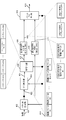
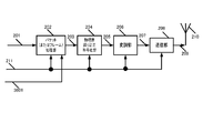
- FIG. 2 shows an example of the configuration of the transmitting apparatus 101 of the transmitting station in FIG.
- the packet (or frame) processing unit 202 receives the information 201 and the control signal 211, performs packet (or frame) processing according to the control signal 211 on the information 201, and performs data processing after packet (or frame) processing. 203 is output. Detailed operations will be described later.
- the physical layer error correction encoding unit 204 receives the data 203 after packet (or frame) processing and the control signal 211 as input, and uses the error correction code scheme (specifically, according to the control signal 211) for the data 203. Error correction code, coding rate) is encoded, and data 205 after error correction coding is output.
- the modulation unit 206 receives the data 205 after error correction coding and the control signal 211 as input, performs modulation by a modulation method according to the control signal 211, and outputs a baseband signal 207.
- the transmission unit 208 receives the baseband signal 207 and the control signal 211, performs signal processing based on the transmission method according to the control signal 211 on the baseband signal 207, and outputs a modulated signal 209.
- the modulated signal 209 is output from the antenna 210 as, for example, a radio wave. Then, the data transmitted with the modulated signal 209 is delivered to the terminal.
- the transmission apparatus is described as an example of transmitting one modulated signal, but the present disclosure is not limited to this, and is disclosed in Patent Document 1, Patent Document 2, and the like.
- a transmission method of transmitting a plurality of modulated signals using a plurality of antennas at the same time and the same frequency may be used.
- the transmission apparatus may use a single carrier scheme, a multicarrier scheme such as an OFDM (orthogonal frequency division) multiplexing scheme, a spread spectrum communication scheme, or the like as a transmission method.
- the transmitting station 101 has been described by way of example of wireless transmission, but a wired transmission method such as a cable may be used.
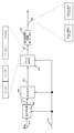
- FIG. 3 shows a configuration example of the receiving device of the terminal shown in FIG.
- the antenna 301 receives the modulated signal transmitted from the transmitting station 101 and outputs it to the receiving unit 303.
- the reception unit 303 performs processing such as frequency conversion and orthogonal demodulation on the reception signal 302 received by the antenna 301 and outputs a baseband signal 304.
- the time and frequency synchronization unit 305 extracts, for example, a preamble, a pilot symbol, a reference symbol, and the like included in the baseband signal 304, performs time synchronization, frequency synchronization, frequency offset estimation, and the like, and outputs a synchronization signal 306.
- the channel estimation unit 307 extracts, for example, a preamble, a pilot symbol, a reference symbol and the like included in the baseband signal 304, performs channel state estimation (channel estimation), and outputs a channel estimation signal 308.
- Control information extraction section 309 extracts control information symbols included in baseband signal 304, performs control information symbol demodulation, error correction decoding, and the like, and outputs control information signal 310.
- the demodulator 311 receives the baseband signal 304, the synchronization signal 306, the channel estimation signal 308, and the control information signal 310 as input, and based on the modulation signal information included in the control information signal 310, the demodulation unit 311 The channel estimation signal 308 is demodulated, the log likelihood ratio of each bit is obtained, and the log likelihood ratio signal 312 is output.
- the operation of the demodulator 311 is described in Patent Document 2, Patent Document 3, and the like.
- the physical layer error correction decoding unit 313 receives the log-likelihood ratio signal 312 and the control information signal 310 as input, and information about the error correction code included in the control information signal 310 (for example, error correction code information, code length (block length ), Encoding rate, etc.), error correction decoding is performed on the log likelihood ratio signal 312 and reception data 314 is output.
- information about the error correction code included in the control information signal 310 for example, error correction code information, code length (block length ), Encoding rate, etc.
- the packet (or frame) processing unit 315 receives the reception data 314 processed by the physical layer error correction decoding 313, the control information signal 310, and the control signal 322, and receives the received data 314 based on the information of the control information signal 310.
- the packet (or frame) is processed to output data 316 after the packet (or frame) processing.
- the packet (or frame) processing unit 315 may change the decoding algorithm based on the control signal 322.
- the packet (or frame) processing unit 315 outputs status information 317 such as an error occurrence status. Detailed operation will be described in detail later.
- transmission by wireless is described as an example, but the present disclosure may use a wired transmission method such as a cable.
- this indication demonstrated in the example which transmits one modulation signal it is not restricted to this, A several modulation signal shown by patent document 1, patent document 2, etc. is made into several. You may use the transmission method which transmits using the same time and the same frequency using an antenna.
- a multicarrier scheme such as an OFDM (orthogonal frequency division) multiplexing scheme, a spread spectrum communication scheme, or the like as a transmission method, processing corresponding to this is performed in each unit. .
- the decoder 382 performs video and audio decoding on the data 316 and outputs a video signal 383 and an audio signal 385.
- the video signal 383 is output to the display unit 384 or output from an external output terminal.
- the audio signal 385 is output as a sound from the speaker 386 or output from an external output terminal.
- the analysis unit 318 receives the state information 317, analyzes the state information, and, for example, information 319 regarding a recommended packet level decoding method (error (erasure) correction decoding method performed by the packet (or) frame processing unit). Is output.
- the display unit 384 displays “recommended packet level decoding method”. Details will be described later.
- control unit 321 receives the setting information 320 and performs detailed settings regarding a packet level decoding method using the display unit 384, for example. And the control part 321 produces
- FIG. 4 shows a configuration of a part of a transmission apparatus related to an error (erasure) correction encoding method for restoring a packet or a frame when the packet or frame is lost in the transmission station 101.
- error (erasure) correction coding at the packet level it is called “error (erasure) correction coding at the packet level”.
- the way of calling is not limited to this. 4 is included in the packet (or frame) processing unit 202 shown in FIG.
- the packet generator 402 receives the information 401 and the control information signal 414, and outputs an information packet 403 based on information on the packet size (the number of bits constituting one packet) included in the control information signal 414.
- the packet generation unit 402 includes information packet # 1, information packet # 2,..., Information packet # (n ⁇ 1), information packet #n (that is, information packet #k (k is 1). And an integer of n or less (n is an integer of 2 or more))).
- the packet generation unit 402 generates information packets # 1 to #n by inserting, for example, known data (Note that an information packet is composed of a plurality of bits).
- Reordering section 404 receives information packet 403 and control information signal 414 as input, rearranges information packet 403 based on the information on the reordering method included in control information signal 414, and reorders data sequence 405. Output. Note that the rearrangement unit 404 does not necessarily perform rearrangement. For example, the rearrangement unit 404 receives information packets # 1 to #n as input, and performs rearrangement within the range of bit sequences constituting the information packets # 1 to #n.
- the encoding unit 406 receives the rearranged data sequence 405 and the control information signal 414 as input, and with respect to the rearranged data sequence 405, an error (erasure) correction encoding method (for example, included in the control information 414). Coding based on the error (erasure) correction coding scheme information used, code length (block length), coding rate, etc.) is performed, and a parity packet 407 is output.
- the encoding unit 406 performs parity packet # 1, parity packet # 2,..., Parity packet # (h-1), parity packet #h (that is, parity packet #k (k is 1). (H is an integer greater than or equal to 1))) (the parity packet is composed of a plurality of bits).
- the error detection code adding unit 408 receives the parity packet 407, adds a CRC (Cyclic Redundancy Check), for example, and outputs a parity packet 409 after the CRC is added in order to detect an error on a packet basis. For this reason, the receiving apparatus can determine whether all the data in the packet is correct or the packet is lost by adding a CRC.
- CRC Cyclic Redundancy Check
- the error detection code adding unit 410 may be any block code or check code that can determine whether all the data in the packet is correct or the packet is missing. A code may be used.
- the error detection code adding unit 408 includes a parity packet # 1 after CRC addition, a parity packet # 2,... After CRC addition, a parity packet # (h-1) after CRC addition, and a CRC addition.
- Parity packet #h parity packet #k after CRC is added (k is an integer of 1 to h. H is an integer of 1 to 1)).
- the error detection code adding unit 410 receives the information packet 403, adds, for example, a CRC and outputs an information packet 411 after the CRC is added in order to detect an error in units of packets. For this reason, the receiving apparatus can determine whether all the data in the packet is correct or the packet is lost by adding a CRC.
- the error detection code adding unit 410 may be any block code or check code that can determine whether all the data in the packet is correct or the packet is missing. Such a code may be used.
- error detection code adding section 410 includes information packet # 1 after CRC addition, information packet # 2, ... after CRC addition, information packet # (n-1) after CRC addition, and after CRC addition.
- Information packet #n that is, information packet #k after CRC is added (k is an integer of 1 or more and n or less (n is an integer of 2 or more))).
- the packet rearrangement unit 412 receives the parity packet 409 after CRC addition and the information packet 411 after CRC addition, sorts the packets, and outputs a packet 413 after rearrangement.
- control information for example, information on the type of information, information on the encoding method of the video encoding (frame rate, compression rate, compression method), etc. (but is not limited thereto). .)) May be included.
- FIG. 5 shows a part of a transmission apparatus related to an error (erasure) correction encoding method for restoring a packet or a frame when a packet or frame loss occurs in the transmission station 101.
- FIG. The structure of is shown.
- the configuration of FIG. 5 is included in the packet (or frame) processing unit 202 in the transmission apparatus shown in FIG.
- the rearrangement unit 502 receives the information 501 and the control information signal 510 as input, rearranges the data of the information 501 based on the information on the rearrangement method included in the control information signal 510, and outputs the rearranged information 503. To do.
- the encoding unit 504 receives the rearranged information 503 and the control information signal 510 as input, and uses the error (erasure) correction encoding method (for example, used) included in the control information 510 for the rearranged information 503. Encoding based on error (erasure) correction encoding scheme information, code length (block length), encoding rate, etc.) is performed, and encoded data 505 is output.
- the code used for encoding may be a systematic code (a code in which an information sequence is included in the codeword as it is) or a non-systematic code.
- the packet generation unit 506 receives the encoded data 505 and the control information signal 510 as input, and based on the information regarding the packet size (the number of bits constituting one packet) included in the control information signal 503, Data 505 is packetized and packet 507 is output.
- the packet generation unit 506 includes the packet # 1, the packet # 2,..., The packet # (m ⁇ 1), the information packet #m (that is, the packet #k (k is 1 or more m (M is an integer of 2 or more)))). If the number of bits of information for generating packets # 1 to #m is insufficient, the encoding unit 504 performs encoding by inserting, for example, known data.
- the error detection code adding unit 508 receives the packet 507, adds a CRC, for example, and outputs a packet 509 after adding the CRC in order to detect an error in units of packets. For this reason, the receiving apparatus can determine whether all the data in the packet is correct or the packet is lost by adding a CRC.
- the error detection code adding unit 508 may be any block code or check code that can determine whether all the data in the packet is correct or whether the packet is missing. A code may be used.
- error detection code adding section 508 includes packet # 1 after CRC addition, packet # 2, after CRC addition, packet # (m ⁇ 1) after CRC addition, and after CRC addition. Packet #m (packet #k after CRC is added (k is an integer of 1 to m (m is an integer of 2 or more))).
- control information for example, information on the type of information, information on the encoding method of the video encoding (frame rate, compression rate, compression method), etc. (but is not limited thereto). .)) May be included.
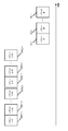
- FIG. 6 shows an example of the packet configuration method described above.
- CRC 602 is used to detect errors.
- Data 603 is data obtained by packet level encoding.
- the control information 601 is information added to a packet, for example, and is exemplified below.
- Packet ID (identification) information In FIG. 4, the number of packets obtained by the error (erasure) correction code is “n + h”. Accordingly, each packet is given any number from “0” to “n + h ⁇ 1” as an ID (identification).
- each of the n information packets and the h parity packets is given any ID from “0” to “n + h ⁇ 1”.
- the number of packets obtained by the error (erasure) correction code is “m”. Therefore, any number among identifiers “0” to “m ⁇ 1” is assigned to each packet.
- each of the m packets is assigned any ID from “0” to “m ⁇ 1”.
- control information is not limited to this.
- the above configuration is merely an example. Therefore, appropriate information is added to the control information depending on the system (a configuration of control information not including the information described above can be considered as a matter of course).
- FIG. 7 is a diagram illustrating an example of a frame configuration.
- the control information may be added in units of a certain number of packets.
- Packet # m-1 (701_m-1), packet #m (701_m) that is, m
- One piece of control information 700 is added to each packet 701.
- control information 700 may be some of the information embedded in the control information described in FIG. Further, the control information 700 may include other control information.
- the transmitting station 101 may transmit data to the terminal by using the packet configuration of FIG. 6 and the frame configuration of FIG. 7 together, or adopt the packet configuration of FIG. 6 (the frame configuration of FIG. 7). Data may be transmitted, or the data may be transmitted using the frame configuration of FIG. 7 (the packet configuration of FIG. 6 is not employed).
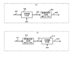
- the transmitting station for example, the preceding stage of the error detection code adding units 408 and 508 of the packet (or frame) processing unit 202 of FIG.
- a control information adding unit may be added to the subsequent stage.
- the transmitting station arranges a control information adding unit 802 before the error detection code adding unit 804.
- the control information adding unit 802 receives the data 801 and the control information 899, and outputs data 803 obtained by adding control information to the data 801. Then, the error detection addition unit 804 outputs data 805 obtained by adding an error detection code to the data 803.
- the transmitting station 101 arranges a control information adding unit 814 after the error detecting code adding unit 812.
- the error detection code adding unit 812 receives the data 811, adds an error detection code to the data 811, and outputs data 813 after the error detection code is added.
- the control information adding unit 814 receives the data 813 and the control information 899, adds control information to the data 813, and outputs the data 815 after adding the control information.
- the transmitting station 101 may arrange a control information adding unit at both the front and rear stages of the error detection code adding unit 804.
- the transmitting station 101 can generate the packet configuration and the frame configuration of FIGS.
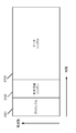
- FIG. 9 shows an example of the frame configuration of the modulation signal transmitted by the transmission apparatus of the transmission station 101 in FIG.
- the horizontal axis represents time
- the vertical axis represents frequency.
- the control information symbol 901 is a symbol for transmitting control information for demodulating data symbols such as a transmission method, information on error correction codes, and a modulation scheme (note that the control information symbol 901 is used at the packet level). It may also contain information about error (erasure) correction codes).
- the pilot symbol 902 is, for example, a PSK (Phase Shift Keying) symbol and can be used for signal detection, channel estimation, frequency offset estimation, and the like in the receiving apparatus.
- the data symbol 903 is used for transmitting data.
- the error (erasure) correction code used at the packet level is a systematic code (a code in which the information sequence is included in the code word as it is).
- the encoding unit receives information as input and obtains parity by performing encoding.
- the packet (or frame) processing unit 202 generates an information packet that configures the packet with information and a parity packet that configures the packet with parity (however, as described above, the information packet includes an error detection code,
- the parity packet may include an error detection code and control information
- Fig. 4 is a configuration diagram of a packet (or frame) processing unit 202 that performs such encoding. Is).
- FIG. 10 shows an example of the configuration of the packet (or frame) processing unit 315 in FIG.
- the error detection unit 1002 receives the reception data 1001 (corresponding to the reception data 314) and the control information signal 1008 (corresponding to the control information signal 310), and based on the information of the control information signal 1008 with respect to the reception data 1001. Perform error detection.
- the packet (or frame) processing unit 315 generates state information 317 for the data 1007 in the subsequent stage of the packet level decoding unit (erasure correction decoding unit) 1006. The operation of the packet (or frame) processing unit 315 will be described with reference to FIG.
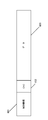
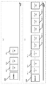
- FIG. 11 shows a configuration of received data 1001 that is input to the error detection unit 1002.
- “information packet 1- # 1” is information packet # 1 of the first block.
- “information packet 1- # 2” is information packet # 2 of the first block.
- “information packet 1- # i” is information packet #i of the first block (where i is an integer of 1 to n).
- parity packet 1- # 1 is parity packet # 1 of the first block.
- parity packet 1- # 2 is parity packet # 2 of the first block.
- parity packet 1- # j is parity packet #j of the first block.
- J is an integer from 1 to h. This encoding method is as described in FIG.
- the encoding unit 406 performs processing for “information packet 1- # 1”, “information packet 1- # 2”,... “Information packet 1-# (n ⁇ 1)” and “information packet 1- # n”.
- “parity packet 1- # 1”, “parity packet 1- # 2”,..., “Parity packet 1-# (h ⁇ 1)” are obtained from the obtained parity.
- "Parity packet 1- # h” is obtained (therefore, the encoding unit 406 performs "information packet k- # 1", "information packet k- # 2", ...
- FIG. 11 shows an example of a state in which the error detection unit 1002 performs error detection.
- the number of information packets is n
- the number of parity packets is h (n is an integer of 1 or more, and h is an integer of 1 or more).
- the error detection unit 1002 determines that there is no error in the data of “information packet 1- # 1” because the result of error detection of “information packet 1- # 1” is “ ⁇ ”. Therefore, it is determined that the data of “information packet 1- # 1” is correct data.
- the error detection unit 1002 determines that there is an error in the data of “information packet 1- # 2” because the result of error detection of “information packet 1- # 2” is “x”. Therefore, the data of “information packet 1- # 2” that is determined to have an error is undefined.
- error detection section 1002 Since the result of error detection of “information packet 1-# (n ⁇ 1)” is “ ⁇ ”, error detection section 1002 has no error in the data of “information packet 1-# (n ⁇ 1)”. to decide. Accordingly, the data of “information packet 1-# (n ⁇ 1)” is determined to be correct data.
- the error detection unit 1002 determines that there is no error in the data of “information packet 1- # n” because the result of error detection of “information packet 1- # n” is “ ⁇ ”. Therefore, it is determined that the data of “information packet 1- # n” is correct data.
- the error detection unit 1002 determines that there is an error in the data of “parity packet 1- # 1” because the result of error detection of “parity packet 1- # 1” is “x”. Therefore, the data of “parity packet 1- # 1” data that is determined to have an error is undefined.
- the error detection unit 1002 determines that there is no error in the data of “parity packet 1- # 2” because the result of error detection of “parity packet 1- # 2” is “ ⁇ ”. Therefore, it is determined that the data of “parity packet 1- # 2” is correct data.
- error detection section 1002 Since the result of error detection of “parity packet 1-# (h ⁇ 1)” is “x”, error detection section 1002 has an error in the data of “parity packet 1-# (h ⁇ 1)”. to decide. Accordingly, the data of “parity packet 1-# (h ⁇ 1)” that is determined to have an error is undefined.
- the error detection unit 1002 determines that there is no error in the data of “parity packet 1- # h” because the result of error detection of “parity packet 1- # h” is “ ⁇ ”. Therefore, it is determined that the data of “parity packet 1- # h” is correct data.
- the error detection unit 1002 may detect whether there is an error in the entire packet data. Alternatively, the error detection unit 1002 divides the packet data into several groups, for example, a data group of group &1; It is also possible to generate the data group of the group & 2,... And detect an error for each data group. At this time, the error detection unit 1002 makes the data of the data group in which the error is detected undefined.
- the error detection unit 1002 includes “information packet k- # 1”, “information packet k- # 2”,..., “Information packet k-# (n ⁇ 1)” “information packet k- # n” in the k-th block. ”And“ parity packet k- # 1 ”“ parity packet k- # 2 ”...“ Parity packet k-# (h ⁇ 1) ”and“ parity packet k- # h ”are similarly detected. I do.
- Storage and rearrangement section 1004 receives packet 1003 after error detection and control information signal 1008 as input, stores packet 1003 after error detection based on control information signal 1008, performs rearrangement, and after rearrangement Data 1005 is output.
- the storage and rearrangement unit 1004 performs “information packet k- # 1” “information packet k- # 2”... “Information packet k-# (n ⁇ 1)” “ “Information packet k- # n” and “parity packet k- # 1” “parity packet k- # 2” ... “parity packet k-# (h-1)” and "parity packet k- # h” are input. , Rearrange the data and output the kth block data.
- the packet level decoding unit (erasure correction decoding unit) 1006 receives the rearranged data 1005, the control information signal 1008, and the control signal 1009 (corresponding to the control signal 322 in FIG. 3), and receives the control information signal 1008 and the control signal 1009. Based on the above, error correction (erasure correction) is performed on the rearranged data 1005, and data 1007 (corresponding to data 316 in FIG. 3) is output.
- the packet level decoding unit (erasure correction decoding unit) 1006 performs “information packet k- # 1” “information packet k- # 2”... “Information packet k-# (n -1) "" information packet k- # n “and” parity packet k- # 1 "" parity packet k- # 2 "! parity packet k-# (h-1) "" parity packet k- # h ”as input, error correction (erasure correction) is performed, and data 1007 is output.
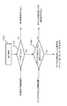
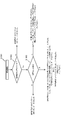
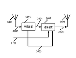
- FIG. 12 shows an example of a detailed configuration of the packet level decoding unit 1006.
- the packet level decoding unit 1006 performs BP (Belief Propagation) decoding and / or maximum likelihood decoding in packet level decoding.
- BP Belief Propagation
- maximum likelihood decoding an outline of Gaussian elimination will be described as an example of BP decoding, as an example of Sum-product decoding and maximum likelihood decoding.
- the present disclosure uses, for example, an LDPC (low density parity check) code (for example, an LDPC block code) as a packet level error (erasure) correction code.
- a (m) is a set of column indexes that are 1 in the m-th row of the parity check matrix H
- B (n) is a set of row indexes that is 1 in the n-th row of the parity check matrix H.
- the packet level decoding unit 1006 uses, for example, the log likelihood ratio ⁇ n of each bit included in the reception data 314 calculated by the physical layer error correction decoding unit 313. (N is an integer from 1 to N).
- the Sum-product decoding algorithm is as follows.
- Step A ⁇ 1 (initialization):
- the likelihood ratio ⁇ mn is set to ⁇ n.
- Step A ⁇ 2 (row processing):
- Step A ⁇ 3 sequence processing:
- Step A ⁇ 4 (calculation of log-likelihood ratio):
- the packet level decoding unit 1006 gives the log-likelihood ratio Ln for n ⁇ [1, N], and performs the determination as follows.
- Step A ⁇ 5 (count of the number of iterations):
- the packet level decoding unit 1006 increments lsum if lsum ⁇ lsum, max, and returns to Step A ⁇ 2.
- the packet level decoding unit 1006 can realize maximum likelihood decoding by solving the simultaneous equations of Expression (7).
- the Gaussian elimination method performs forward elimination and backward substitution.
- forward erasure and backward substitution will be described.
- the packet level decoding unit 1006 obtains (x1, x2,..., Xn) by simultaneous linear equations.
- the packet level decoding unit 1006 can obtain the following expression by applying the row operation to Expression (9) (forward erasure).
- the packet level decoding unit 1006 can obtain xn from the last line of the equation (9), and can obtain xn-1 by using the obtained xn.
- the packet level decoding unit 1006 can obtain xn ⁇ 2,..., X2, x1 by performing the same operation. This can be expressed by the following equation (backward substitution).
- the packet level decoding unit 1006 can realize maximum likelihood decoding by solving Equation (7) using Gaussian elimination.
- the decoding method of the present disclosure In the error (erasure) correction capability, the characteristics when the maximum likelihood decoding is used are superior to the characteristics when the BP decoding is used. On the other hand, in the operation scale, the operation scale of BP decoding is smaller than the operation scale of maximum likelihood decoding. Considering the above, it is desired that the decoding method be realized by a method having a high error (erasure) correction capability and a small operation scale.
- Non-Patent Document 1 discloses a decoding method that combines BP decoding and Gaussian elimination. The outline is as described above. The present disclosure proposes a decoding method that realizes further reduction in the operation scale. This will be described below.
- yi i is an integer of 1 or more and N or less, and yi is any one of “0”, “1”, and “indefinite (disappearance)”.
- i is an integer of 1 to N, and zi is any one of “0”, “1”, and “indefinite (cannot be restored by BP decoding)”.
- qi i is an integer of 1 or more and N or less, and qi is any one of “0”, “1”, and “indefinite”.
- the control unit 1207 operates the units (BP decoding unit 1202, maximum likelihood decoding unit 1204, and selection unit 1209) based on the data 1201, the control signal 1206 (corresponding to the control signal 322 in FIG. 3), and the error state of the data.
- An operation control signal 1208 for control is output. The operation control method will be described later in detail.
- the BP decoding unit 1202 receives the data 1201, the operation control signal 1208, and the control information signal 1211, and determines whether or not to perform BP decoding on the data 1201 based on the operation control signal 1208 and the control information signal 1211.
- a reception sequence 1203 after BP decoding is output. A method for determining whether or not to perform BP decoding will be described in detail later.
- the maximum likelihood decoding unit 1204 determines whether to perform maximum likelihood decoding on the received sequence 1203 after BP decoding based on the operation control signal 1208 and the control information signal 1211, and performs maximum likelihood decoding. Decoding operation is performed on reception sequence 1203 after BP decoding, and reception sequence 1205 after maximum likelihood decoding is output. A method for determining whether to perform maximum likelihood decoding will be described in detail later.
- both the BP decoding unit 1202 and the maximum likelihood decoding unit 1204 have the control information signal 1208 as input, and information (code length, encoding) of packet level error (erasure) correction codes included in the control information signal 1211. Decoding based on the rate). Note that when the data 1201 is not subjected to error (erasure) correction coding at the packet level, the packet level decoding unit 1006 does not perform error (erasure) correction decoding.
- the selection unit 1209 receives the data 1201, the reception sequence 1203 after BP decoding, the reception sequence 1205 after maximum likelihood decoding, the operation control signal 1208, and the control information signal 1211, and based on the operation control signal 1208 and the control information signal 1211, One of data 1201, received sequence 1203 after BP decoding, and received sequence 1205 after maximum likelihood decoding is selected, and selection data 1210 is output. Note that, as described above, in FIG. 12, systematic codes are handled as packet-level error (erasure) correction codes. Therefore, the selection data 1210 may include information-related data.
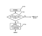
- FIG. 13 shows a flowchart of the basic operation of the packet level decoding unit 1006 in this embodiment.
- the determination of the flowchart is performed by, for example, the control unit 1207 in FIG.
- the procedure is as follows.
- Step 1 S1301
- the control unit 1207 instructs each unit to start “decoding” (the determination of “decoding start” is performed by, for example, the control information signal 1206).
- Step 2 The control unit 1207 determines whether or not to perform BP decoding based on the control signal for BP decoding.
- the control signal for BP decoding is included in the control signal 1206 and the control information signal 1211.
- the selection unit 1209 selects the data 1201 and outputs it as selection data (S1302: NO).
- the BP decoding unit 1202 performs BP decoding on the data 1201 and outputs the reception sequence 1203 after BP decoding as selection data (S1302: YES).
- Step 3 The control unit 1207 determines whether or not to perform decoding by the Gaussian elimination method based on the control signal for the Gaussian elimination method (control signal for maximum likelihood decoding) (note that The control signal for the Gaussian elimination method is included in the control signal 1206 and the control information signal 1211.
- control signal for the Gaussian elimination method is included in the control signal 1206 and the control information signal 1211.
- the selection unit 1209 When decoding by Gaussian elimination is not performed, the selection unit 1209 outputs either the data 1201 or the reception sequence 1203 after BP decoding (S1303: NO).
- the maximum likelihood decoding unit 1204 When performing decoding using the Gaussian elimination method, the maximum likelihood decoding unit 1204 performs, for example, decoding using the Gaussian elimination method on the reception sequence 1203 after BP decoding, and outputs a reception sequence 1205 after maximum likelihood decoding ( S1303: YES).
- the packet level decoding unit 1006 performs the basic decoding process as described above.
- the selection unit 1209 in FIG. 12 selects data to be output based on the control signal 1206 and the control information signal 1211.
- control information signal 1211 includes information indicating whether or not packet-level error (erasure) correction encoding is performed.
- the selection unit 1209 receives the control information signal 1211 and outputs data 1201 as selection data 1210 when the control information signal 1211 indicates that “packet level error (erasure) correction coding is not performed”. (S1302: NO).
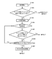
- FIG. 14 shows a flowchart of the packet level decoding unit 1006 in the present embodiment.
- the determination of the flowchart is performed by, for example, the control unit 1207, the BP decoding unit 1202, the maximum likelihood decoding unit 1204, and the selection unit 1209 in FIG.
- the packet level decoding unit 1006 performs the following procedure (however, in the flowchart of FIG. 14, it is assumed that the data 1201 has been subjected to error (erasure) correction coding at the packet level). .
- Step 1: S1401 The control unit 1207 instructs each unit (the BP decoding unit 1202, the maximum likelihood decoding unit 1204, and the selection unit 1209) to “decode start”. Performed by the control information signal 1211).
- Step 2 For example, the control unit 1207 or the BP decoding unit 1202 determines whether “all information packets (or information) have been obtained” (in this embodiment, the packet Since a level error (erasure) correction code is based on the precondition that a systematic code is used, the data 1201 includes an information packet or information).
- the BP decoding unit 1202 does not perform error (erasure) correction decoding (S1402: YES). Therefore, the selection unit 1209 outputs the data 1201 or information extracted from the data 1201 as selection data 1210.
- the BP decoding unit 1202 starts BP decoding (S1403).
- the packet level decoding unit 1006 completes the decoding process, so that the decoding unit (for example, BP decoding unit 1202 and The operation scale of the maximum likelihood decoding unit 1204) can be reduced. Thereby, the packet level decoding unit 1006 can reduce the power consumption of the decoding unit.
- Step 3 S1404.
- the BP decoding unit 1202 starts counting the number of iterations after starting BP decoding. Note that the BP decoding unit 1202 sets the maximum number of iterations to Nmax.
- the BP decoding unit 1202 first checks whether the number of iterations n is smaller than Nmax (S1404). The BP decoding unit 1202 performs a decoding process when the number of iterations n is smaller than Nmax.
- the BP decoding unit 1202 determines whether “all information packets (or information) have been obtained” for the data obtained by performing the decoding process (S1405).
- BP decoding section 1202 completes BP decoding when all information packets (or information) are obtained, and outputs received sequence 1203 after BP decoding. Then, the selection unit 1209 outputs, as selection data 1210, information extracted from the reception sequence 1203 after BP decoding or the reception sequence 1203 after BP decoding (S1405: YES).
- BP decoding section 1202 completes the n-th iterative decoding when all information packets (or information) are not obtained (S1405: NO).
- the BP decoding unit 1202 confirms whether or not the number of iterations n is smaller than Nmax (S1406). If the number of iterations n is smaller than Nmax, the BP decoding unit 1202 performs the (n + 1) th decoding process (S1406: YES).
- the maximum likelihood decoding unit 1204 starts decoding by the Gaussian elimination method (S1407). .
- the packet level decoding unit 1006 reduces the operation scale of the decoding unit by completing the decoding process when all the information packets (or information) are obtained in the BP decoding unit 1202. Thus, the power consumption of the decoding unit can be reduced.
- the maximum likelihood decoding unit 1204 receives the received sequence after the BP decoding process, performs decoding by Gaussian elimination, for example, and outputs the received sequence 1205 after the maximum likelihood decoding.
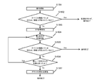
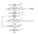
- FIG. 15 shows a flowchart of the packet level decoding unit 1006 in the present embodiment.
- the determination of the flowchart is performed by, for example, the control unit 1207, the BP decoding unit 1201, the maximum likelihood decoding unit 1204, and the selection unit 1209 in FIG.
- the packet level decoding unit 1006 performs the following procedure (however, in the flowchart of FIG. 15, it is assumed that the data 1201 has been subjected to error (erasure) correction coding at the packet level). .
- Step 1: S1501 The control unit 1207 instructs each unit (the BP decoding unit 1202, the maximum likelihood decoding unit 1204, and the selection unit 1209) to “decode start”. Performed by the control information signal 1211).
- Step 2 For example, the control unit 1207 or the BP decoding unit 1202 determines whether “all information packets (or information) have been obtained” (in this embodiment, the packet Since a level error (erasure) correction code is based on the precondition that a systematic code is used, the data 1201 includes an information packet or information).
- the BP decoding unit 1202 does not perform error (erasure) correction decoding (S1502: YES). Therefore, the selection unit 1209 outputs the data 1201 or information extracted from the data 1201 as selection data 1210.
- the BP decoding unit 1202 starts BP decoding on the data 1201 (S1503).
- the packet level decoding unit 1006 completes the decoding process, and the decoding unit packet level decoding unit 1006 The operation scale can be reduced, and the packet level decoding unit 1006 has an effect that the power consumption of the decoding unit can be reduced.
- Step 3 After starting the BP decoding, the BP decoding unit 1202 starts counting the number of iterations (S1504).
- the BP decoding unit 1202 determines whether “all information packets (or information) have been obtained” for the data obtained by performing the decoding process n times (S1505). If all the information packets (or information) are obtained, the BP decoding unit 1202 completes the BP decoding and outputs the reception sequence 1203 after the BP decoding (S1505: YES).
- the selection unit 1209 outputs the reception sequence 1203 after BP decoding or information extracted from the reception sequence 1203 after BP decoding as selection data 1210.
- the BP decoding unit 1202 completes the n-th iterative decoding, and proceeds to S1506 (S1505: NO).
- the packet level decoding unit 1006 reduces the operation scale of the decoding unit by completing the decoding process when all the information packets (or information) are obtained in the BP decoding unit 1202. Thus, the power consumption of the decoding unit can be reduced. (Here, it is described that “the number of iterations is counted”, but the number of iterations may not be counted).
- Step 4: S1506 the BP decoding unit 1202 compares the data obtained by the previous (n ⁇ 1) th decoding process with the data obtained by the current (nth) decoding process. If the data obtained by the previous decoding process and the data obtained by the current decoding process are the same, the BP decoding unit 1202 can obtain an effect of error (erasure) correction even if the iterative process is performed further. If it is determined that it is not possible, the process proceeds to the next step (S1507) (S1506: NO).
- the BP decoding unit 1202 determines that the data obtained by the previous decoding process is different from the data obtained by the current decoding process (there is data that has been subjected to error (erasure) correction by the current decoding process). If it is determined, the process shifts to the next (n + 1) iteration process after BP decoding (S1506: YES).
- Step 5 S1507
- Maximum likelihood decoding section 1204 receives reception sequence 1203 after BP decoding, performs decoding by Gaussian elimination, for example, and outputs reception sequence 1205 after maximum likelihood decoding.
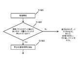
- the packet level decoding unit 1006 may perform a process as shown in FIG. 16 before starting the decoding process shown in FIGS. In FIG. 16, the packet level decoding unit 1006 first determines whether or not a packet having a data amount larger than the data amount of the information packet has been obtained (S1601).
- the packet level decoding unit 1006 does not perform any decoding processing and passes the obtained packet data to the next layer (for example, the application layer). This is because the packet level decoding unit 1006 cannot obtain all the information bits because the simultaneous equations cannot be solved (S1602: NO).
- the packet level decoding unit 1006 When the number of bits of the received data is 720 bits or more (or more) (S1602: YES), the packet level decoding unit 1006 performs, for example, the decoding process of FIGS. 13, 14, and 15 (S1603).
- the packet level decoding unit 1006 can reduce the operation scale by omitting the decoding process, the power consumption of the decoding unit can be reduced.
- the operation of the packet level decoding unit 1006 in the present embodiment may be the operation shown in FIG. In FIG. 17, first, the packet level decoding unit 1006 determines whether or not packet layer error correction coding has been performed (S1701).
- the packet level decoding unit 1006 If the packet layer error correction coding is not performed, the packet level decoding unit 1006 does not perform processing (S1702: NO). On the other hand, when error correction coding of the packet layer is performed (S1702: YES), the packet level decoding unit 1006 performs BP decoding and / or decoding using Gaussian elimination (S1703).
- Each receiving device may be configured to set the decoding method for each terminal by displaying a setting screen related to decoding. Below, the setting method is demonstrated.
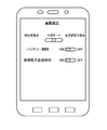
- FIG. 18 shows an example of setting items displayed on the terminal screen, for example.
- each receiving apparatus terminal performs input regarding the item to be set from the display unit 384 illustrated in FIG.
- FIG. 18 shows an example of an input screen on which setting items are displayed.
- the receiving device (terminal) can select “high quality priority”, “low power consumption priority (saving mode)”, or “intermediate mode”.
- “High quality priority” the receiving device (terminal) selects a decoding method capable of performing high error (erasure) correction, and when “Low power consumption priority (saving mode)” is selected.
- “intermediate mode” a mode that achieves both data quality and low power consumption is selected. Detailed operations will be described later.
- the receiving device (terminal) can select “ON” or “OFF” of battery control.
- the receiving apparatus (terminal) selects an appropriate signal processing method based on the remaining battery level of the receiving apparatus (terminal) and performs packet level decoding.
- the receiving device (terminal) performs packet-level decoding by the set signal processing method regardless of the remaining power of the battery of the receiving device (terminal). Detailed operations will be described later.
- the receiving device (terminal) can select “ON” or “OFF” for automatic processing capability detection.
- the processing apparatus automatic detection “ON” is selected, the receiving apparatus (terminal) automatically measures the signal processing capacity, selects an appropriate signal processing method based on the measurement result, and performs packet level decoding.
- the processing apparatus automatic detection “OFF” is selected, the receiving apparatus (terminal) omits measurement of the signal processing capacity and performs packet-level decoding using the set signal processing method. Detailed operations will be described later.
- the receiving device determines a packet level decoding method based on the setting in FIG.
- FIG. 19 shows an example of a flowchart regarding determination of a decoding method.
- the receiving apparatus performs control according to the following procedure shown in FIG. .
- Step 1 S1901
- the control unit 1207 starts setting a packet-level decoding method at a certain timing (for example, at the start of application operation, power-on, application startup, etc.).
- Step 2 The reception device (terminal) determines whether the signal “processing capacity is sufficient” of the reception device. If it is determined that the signal processing capability is not sufficient (S1902: No), the receiving apparatus outputs data without performing BP decoding and maximum likelihood decoding. This is because the received data is a systematic code, and thus the receiving device can obtain information (data) in which no erasure has occurred in the received data even if decoding of the received data is omitted. That is, the selection unit 1209 outputs the data 1201 as selection data 1210. If the receiving apparatus determines that the signal processing capability is sufficient (S1902: Yes), the receiving apparatus proceeds to the next step (S1903).
- Step 3 The receiving device (terminal) confirms the setting of power consumption (S1903). That is, the receiving apparatus (terminal) confirms whether the “high quality priority”, “low power consumption priority (saving mode)”, or “intermediate mode” mode shown in FIG. 18 is selected. .
- the receiving apparatus When the “high quality priority” mode is set (S1903: large), the receiving apparatus (terminal) performs “BP decoding, then performs decoding using the Gaussian elimination method, and packet (or data) Output ".
- the receiving apparatus does not perform both BP decoding and decoding using the Gaussian elimination method, but uses the Gaussian elimination method as shown in FIGS. 14, 15, and 16. In the case where decoding is necessary, BP decoding and decoding using Gaussian elimination are performed, and in the case where decoding is not necessary, either BP decoding and decoding without Gaussian elimination are performed, or BP decoding and The Gaussian elimination method is omitted.
- the receiving device When the battery control shown in FIG. 18 is “ON”, the receiving device (terminal) “performs BP decoding and outputs a packet (or data)” based on the remaining battery level.
- the receiving device omits BP decoding in the case where BP decoding is not necessary, or “without performing BP decoding.
- Output packet (or data) "(S1402: YES, S1502: YES, S1602: NO, S1702: NO).
- the receiving apparatus may omit decoding using the Gaussian elimination method.
- the receiving apparatus When the receiving apparatus is set to “intermediate mode” (S1903: middle), “perform BP decoding and output packet (or data)”. Note that, as shown in FIGS. 14, 15, 16, and 17, the receiving device (terminal) omits BP decoding in a case where BP decoding is not necessary (S1402: YES, S1502: YES, S1602). : NO, S1702: NO).
- the receiving device when the battery control in FIG. 18 is “ON”, the receiving device “outputs a packet (or data) by omitting BP decoding” based on the remaining battery level. At this time, the receiving apparatus may omit decoding using the Gaussian elimination method.
- the receiving device When the “low power consumption priority” mode is set (S1903: small), the receiving device “outputs a packet (or data) without performing BP decoding”.
- the receiving apparatus terminal
- decoding using the Gaussian elimination method also omits decoding using the Gaussian elimination method.
- the receiving device can realize appropriate control based on the capacity of the battery (battery) while improving the reception quality of data and reducing the power consumption.
- FIG. 20 is a flowchart regarding determination of a packet level decoding method, and shows an example different from FIG. Note that the setting screen may exist as shown in FIG. 18, or may be set each time based on the setting procedure shown in FIG.
- Step 1 Either “high quality mode” or “low power consumption mode” is selected (S2002).
- the receiving device (terminal) When “low power consumption mode” is selected in S2002: Next, the remaining battery level is confirmed (S2005). When the remaining battery level is not sufficient (S2005: NO), the receiving device (terminal) “outputs a packet (or data) without performing BP decoding”. When the remaining battery level is sufficient (S2005: YES), the receiving device (terminal) “performs BP decoding and outputs a packet (or data)”. As shown in FIGS. 14, 15, 16, and 17, the receiving device (terminal) omits BP decoding in the case where BP decoding is not necessary.
- the receiving device When the battery control in FIG. 18 is “ON”, the receiving device (terminal) “outputs a packet (or data) without performing BP decoding” based on the remaining battery level. Note that the receiving apparatus (terminal) may omit decoding using the Gaussian elimination method.
- the receiving device (terminal) confirms (signal) processing capability (S2003). For example, the receiving device (terminal) executes a test program. Note that the processing capability can be confirmed by executing the test program in any case of this specification.
- the receiving device When it is determined that “the processing capability is low” (S2003: low): The receiving device (terminal) “outputs a packet (or data) without performing BP decoding”. The receiving apparatus (terminal) also omits decoding using the Gaussian elimination method.
- the receiving device determines that “processing ability is medium” (S2003: medium): The receiving device (terminal) checks the remaining battery level (S2006). When the remaining battery level is insufficient (S2006: NO), the receiving device (terminal) “outputs a packet (or data) without performing BP decoding”.
- the receiving device (terminal) “performs BP decoding and outputs a packet (or data)”. As shown in FIGS. 14, 15, 16, and 17, the receiving device (terminal) omits BP decoding when BP decoding is not necessary.
- the receiving device When the battery control in FIG. 18 is “ON”, the receiving device (terminal) “outputs a packet (or data) without performing BP decoding” based on the remaining battery level. Note that the receiving apparatus (terminal) may omit decoding using the Gaussian elimination method.
- the receiving device checks the remaining battery level. When the remaining battery level is low (S2004: small), the receiving apparatus (terminal) “outputs a packet (or data) without performing BP decoding”.
- the receiving device (terminal) When the remaining battery level is medium (S2004: middle), the receiving device (terminal) “performs BP decoding and outputs a packet (or data)”. As shown in FIGS. 14, 15, 16, and 17, the receiving device (terminal) omits BP decoding when BP decoding is not necessary.
- the receiving device When the battery control in FIG. 18 is “ON”, the receiving device (terminal) “outputs a packet (or data) without performing BP decoding” based on the remaining battery level. Note that the receiving apparatus (terminal) may omit decoding using the Gaussian elimination method.
- the receiving device performs “BP decoding, then decoding using the Gaussian elimination method, and outputs a packet (or data) "
- the receiving apparatus performs both BP decoding and Gaussian erasing in cases where decoding using Gaussian erasing is necessary.
- decoding using the Gaussian elimination method may be omitted.
- the receiving device When the battery control in FIG. 18 is “ON”, the receiving device (terminal) “performs BP decoding and outputs a packet (or data)” based on the remaining battery level. 14, 15, 16, and 17, the receiving apparatus (terminal) may omit the BP decoding and the Gaussian elimination method, or may perform the BP decoding and perform the Gaussian elimination method. May be omitted.
- the control unit 1207 receives the data 1201, the reception sequence 1203 after BP decoding, and the reception sequence 1205 after maximum likelihood decoding, and after each decoding and before erasure correction Depending on the packet error (erasure) state of the data, a display that prompts the user to change the decoding method may be performed.
- the BP decoding can be appropriately omitted as the receiving apparatus (terminal) performs “BP decoding and outputs a packet (or data)”.
- the control unit 1207 may instruct the display unit 384 to display “It is possible to set a high-quality reception method”.
- the receiving apparatus (terminal) transmits the information “whether or not the user agrees to the setting to the high quality receiving method” to the control unit 1207 by the control signal 1206.
- the control unit 1207 may change the decoding method based on information from the user.
- the receiving device changes to “perform BP decoding, then perform decoding using Gaussian elimination and output packet (or data)”.
- the BP decoding and the Gaussian elimination method may be omitted as appropriate.
- the BP decoding can be appropriately omitted as the receiving apparatus (terminal) “performs BP decoding and outputs a packet (or data)”. ) And the number of lost packets is small, the control unit 1207 may instruct the display unit 384 to display “power consumption can be reduced”.
- the receiving device transmits information indicating whether or not the user agrees to reduce power consumption to the control unit 1207 by a control signal 1206.
- the control unit 1207 may change the decoding method based on information from the user.
- the receiving device changes to “output packet (or data) without performing BP decoding” (does not perform decoding using Gaussian elimination).
- the receiving apparatus is set to “output a packet (or data) without performing BP decoding” (does not perform decoding using Gaussian elimination), and there are many lost packets.
- the control unit 1207 may instruct the display unit 384 to display “can be set to a high quality reception method”.
- the receiving apparatus (terminal) transmits the information “whether or not the user agrees to the setting to the high quality receiving method” to the control unit 1207 by the control signal 1206.
- the control unit 1207 may change the decoding method based on information from the user.
- the receiving apparatus performs “BP decoding, and then performs decoding using Gaussian elimination and outputs a packet (or data)” (note that the receiving apparatus (terminal)
- the decoding and Gaussian elimination methods can be omitted as appropriate as shown in FIGS. 14, 15, 16, and 17, or “BP decoding is performed and packets (or data) are output.
- the receiving device (terminal) can be changed to any one of the decoding methods as shown in FIGS. 14, 15, and 16 as appropriate.)
- the receiving apparatus performs “BP decoding, and then performs decoding using Gaussian elimination and outputs a packet (or data)” (note that the receiving apparatus (terminal) ),
- the BP decoding and Gaussian elimination methods can be omitted as appropriate as shown in FIGS. 14, 15, 16, and 17.
- the control unit 1207 displays The unit 384 may be instructed to display “power consumption can be reduced”.
- the receiving device transmits information indicating whether or not the user agrees to reduce power consumption to the control unit 1207 by a control signal 1206.
- the control unit 1207 may change the decoding method based on information from the user.
- the receiving apparatus performs a decoding method of “output a packet (or data) without performing BP decoding” (does not perform decoding using Gaussian elimination), or “performs BP decoding. And a packet (or data) is output ”(note that the receiving apparatus (terminal) can omit BP decoding as appropriate as shown in FIGS. 14, 15, 16, and 17). Can be changed to
- the receiving device prompts the user to change the signal processing method (decoding processing method) or to change the set contents depending on the data error (erasure) state.
- the content “prompt for change” By displaying the content “prompt for change” on the display unit 384, both high data reception quality and low power consumption can be achieved.
- the quality setting screen is shown in FIG. 18, the content to be set is not limited to that in FIG. 18, and for example, each decoding method may be set to be valid / invalid. .
- the receiving device (terminal) performs “BP decoding, and then performs decoding using Gaussian elimination and outputs a packet (or data)” (note that the receiving device (terminal) performs BP decoding. And Gaussian elimination can be omitted as appropriate as shown in FIGS. 14, 15, 16, and 17).
- Data) (note that the receiving device (terminal) can omit BP decoding as shown in FIGS. 14, 15, 16, and 17 as appropriate).
- “valid / invalid” may be set for “output packet (or data) without performing BP decoding” (without performing decoding using Gaussian elimination).
- the receiving device displays the contents of “prompt for change” on the display unit 384 so as to prompt the user to change the validity / invalidity according to the error (erasure) state of the data. May be.
- the decoding control method is described, and the calculation scale can be reduced by carrying out as in this embodiment. As a result, the power consumption in the decoding process part can be reduced.
- sum-product decoding has been described as an example of BP decoding and Gaussian elimination has been described as an example of maximum likelihood decoding.
- min-sum decoding is used as BP decoding.
- maximum likelihood decoding a Gauss-Jordan method, a Gauss-Seidel method, an LU decomposition, or the like may be used ( In the case of maximum likelihood decoding, an operation for solving simultaneous equations is performed).
- the relationship between the transmission station and the terminal, the configuration of the transmission device of the transmission station (FIG. 2), the configuration of the reception device of the terminal (FIG. 3), and the point of performing packet level error (erasure) correction coding The same as in the first embodiment.
- packet level encoding / decoding different from the first embodiment will be described.
- the configuration of the transmission apparatus of the transmission station is as shown in FIG. 2 and has been described in the first embodiment, and thus description thereof is omitted here. Further, the configuration of the receiving device of the terminal is as shown in FIG. 3 and has been described in Embodiment 1, and therefore description thereof is omitted here.
- FIG. 22 shows a configuration of a part related to an error (erasure) correction coding scheme that enables restoration when a packet or frame loss occurs in the transmission apparatus of the transmission station 101, which is different from FIG. . 22 that operate in the same manner as in FIG. 4 are denoted by the same reference numerals and description thereof is omitted.
- the parallel-serial converter 2202 receives the video # 1 stream packet 2201_1, the video # 2 stream packet 2201_2,..., The video #L stream packet 2201_L, and the control information signal 414 as inputs. Based on the information regarding the number of streams included in 414, parallel-serial conversion is performed, and a packet 403 (information of one or more streams) including information of a plurality of streams is output.
- video # 1 stream packet 2201_1 is described as “video”, but may include voice, sound (audio), subtitles, character information, and the like, and may also include voice, sound (audio), and text. It may be information. This also applies to the following.
- the parallel-serial conversion unit 2202 is described. However, when the input data is one packet including information of a plurality of streams, the transmission apparatus can omit the parallel-serial conversion unit 2202. .
- Reordering section 404 receives packet 403 including information on a plurality of streams and control information signal 414 as input, rearranges the data of packet 403 based on the information on the reordering method included in the control information, and after reordering The data series 405 is output. Note that the transmission device does not necessarily have to be rearranged.
- the encoding unit 406 receives the rearranged data sequence 405 and the control information signal 414 as input, and includes an error (erasure) correction method (for example, information on error (erasure) correction method to be used, code) included in the control information signal 414. Based on the information on the length (block length), coding rate, etc.) and the number of streams, the rearranged data sequence 405 is encoded and a parity packet 407 is output.
- an error (erasure) correction method for example, information on error (erasure) correction method to be used, code
- the error detection code adding unit 408 receives the parity packet 407, adds, for example, a CRC and outputs a parity packet 409 after the CRC is added in order to detect an error in units of packets.
- the receiving apparatus can determine whether all the data in the packet is correct or the packet is lost by adding a CRC by the error detection code adding unit 408.
- the CRC has been described as an example, if the block code or check code enables determination of whether all the data in the packet is correct or the packet has been lost, A code may be used.
- the error detection code adding unit 410 receives the information packet 403, adds, for example, a CRC and outputs an information packet 411 after the CRC is added in order to detect an error in units of packets.
- the receiving apparatus can determine whether all the data in the packet is correct or the packet is lost by adding a CRC by the error detection code adding unit 410.
- the CRC has been described as an example, if the block code or check code enables determination of whether all the data in the packet is correct or the packet has been lost, A code may be used.
- the packet rearrangement unit 412 receives the parity packet 409 after CRC addition and the information packet 411 after CRC addition, sorts the packets, and outputs a packet 413 after rearrangement.
- control information for example, information on the type of information, information on the encoding method of the video encoding (frame rate, compression rate, compression method), etc. (but is not limited thereto). ) May be included.
- FIG. 23A shows the relationship between an information packet and a parity packet whose number of streams is 1 (that is, in FIG. 22, the transmission apparatus transmits a packet 2201_1 of the stream of video # 1).
- the encoding unit 406 in FIG. 22 receives an information packet and performs error (erasure) correction encoding to obtain a parity packet.
- the encoding unit 406 includes “information packet S $ 1-1”, “information packet S $ 1-2”, “information packet S $ 1-” among the stream information packets of video # 1. 3 ”,...,“ Information packet S $ 1- (n ⁇ 1) ”,“ information packet S $ 1-n ”(n is an integer greater than or equal to 2) information packets with an error ( Erasure) correction encoding is performed, and "parity packet # 1", “parity packet # 2", “parity packet # 3", ..., "parity packet # (h-1)", “parity packet #h” H (h is an integer of 1 or more) parity packets. That is, the encoding unit 406 “generates h parity packets for every n information packets of the stream of the video # 1”.
- FIG. 23B shows an information packet with the number of streams being 2 (that is, in FIG. 22, the transmitting apparatus transmits the packet 2201_1 of the video # 1 stream and the packet 2201_2 of the video # 2 stream).
- the relationship with a parity packet is shown.
- the encoding unit 406 in FIG. 22 receives an information packet and performs error (erasure) correction encoding to obtain a parity packet.
- the encoding unit 406 includes “information packet S $ 1-1”, “information packet S $ 1-2”, and “information packet S $ 1” among the information packets of the stream of video # 1. -3 ", ...," Information packet S $ 1- (n-1) "," Information packet S $ 1-n “(n is an integer of 2 or more) information packets, "Packet S $ 2-1", “information packet S $ 2-2", “information packet S $ 2-3", ..., “information packet S $ 2- (n-1)”, “information packet Error (erasure) correction coding is performed on a total of 2 ⁇ n information packets (n is an integer of 2 or more) of “S $ 2-n” (n is an integer of 2 or more), and “parity packet # 1” , “Parity packet # 2”, “parity packet # 3”,..., “Parity packet # (2 ⁇ h ⁇ 1) ”,“ Parity packet # 2 ⁇ h ”, 2 ⁇ h (h is an integer of 1 or more) parity packets.
- the encoding unit 406 performs the following operation: “2 ⁇ h packets for every 2 ⁇ n packets of“ n information packets of the video # 1 stream ”and“ n information packets of the video # 2 stream ”. Generate a parity packet. "
- 23C shows the number of streams u (that is, in FIG. 22, the transmitting apparatus transmits the packet 2201_u of the stream of video #u from the packet 2201_1 of the stream of video # 1) (u is an integer of 1 or more. ) Shows the relationship between the information packet and the parity packet.
- the encoding unit 406 in FIG. 22 receives an information packet and performs error (erasure) correction encoding to obtain a parity packet.
- the information packets of the stream of the video #j are “information packet S $ j ⁇ 1”, “information packet S $ j-2”, “information packet S $ j-3”,.
- the encoding unit 406 performs the following operation on the basis of “u ⁇ h parity for each of a total of u ⁇ n packets from the n information packets of the video # 1 stream to the n information packets of the video #u stream. Generate a packet. "
- the transmission apparatus in order to transmit the packet of the video # 1 stream, the transmission apparatus has an error (erasure) of a block length of 2880 bits composed of 1440-bit information and 1440-bit parity. Encoding for erasure correction is performed using a correction (block) code.
- the transmitting apparatus transmits a packet of the video #u stream from the video # 1 stream, and includes a block composed of 1440 ⁇ u bit information and 1440 ⁇ u bit parity. Encoding erasure correction is performed using an error (erasure) correction (block) code having a length of 2880 ⁇ u bits.
- the transmitting apparatus corrects an error (erasure) of a block length a + b bits composed of a-bit information and b-bit parity in order to transmit the packet of the stream of video # 1.
- Encoding for erasure correction is performed using a (block) code (a is an integer of 1 or more, and b is an integer of 1 or more).
- the transmission apparatus is configured with 2 ⁇ a-bit information and 2 ⁇ b-bit parity in order to transmit the video # 1 stream packet and the video # 2 stream packet.
- the error (erasure) correction (block) code having a block length of 2 ⁇ (a + b) bits, encoding of erasure correction is performed.
- the transmitting apparatus transmits a packet of the video #u stream from the video # 1 stream, and is a block composed of a ⁇ u bit information and b ⁇ u bit parity. Encoding for erasure correction is performed using an error (erasure) correction (block) code of long (a + b) ⁇ u bits.
- the configuration of the receiving device that receives the signal transmitted by the transmitting device is as shown in FIG.
- the configuration of the packet (or frame) processing unit 315 in FIG. 3 is as shown in FIG. 24, and components that operate in the same manner as in FIG.
- the error detection unit 1002 receives the reception data 1001 and the control information signal 1008, and receives the reception data based on, for example, information on the packet configuration in the control information signal 1008 (for example, information on packet length, information on packet order, etc.). Knowing the configuration of the packet 1001, the packet is detected based on the learned configuration, and the packet 1003 after the error detection is output.
- information on the packet configuration in the control information signal 1008 for example, information on packet length, information on packet order, etc.
- the storage and rearrangement unit 1004 receives the packet 1003 after error detection and the control information signal 1008 as input, and information on the packet configuration in the control information signal (for example, information on packet length, information on packet order, error (erasure)). Based on the code length of the correction code, the coding rate of the error (erasure) correction code, etc.), the packet 1003 after the error detection is stored, further rearranged, and the rearranged data 1005 is output.
- the packet level decoding unit (erasure correction decoding unit) 1006 receives the rearranged data 1005, the control information signal 1008, and the control signal 1009 as input, and information on the packet configuration in the control information signal 1008 (for example, packet length information, packet Packet level decoding is performed on the rearranged data 1005 on the basis of the order information, the code length of the error (erasure) correction code, the coding rate of the error (erasure) correction code, and the like. For example, decoding corresponding to any of FIG. 23A, FIG. 23B, and FIG. 23C is performed, and data 1007 is output.
- the packet level decoding unit (erasure correction decoding unit) 1006 may output an information packet as the data 1007, or may output both an information packet and a parity packet. Further, the packet level decoding unit (erasure correction decoding unit) 1006 may determine whether or not to perform packet level decoding based on the control signal 100. Note that the packet level decoding method is the same as that described in the first embodiment with reference to FIG.
- the stream selection unit 2401 receives the data 1007 and the control signal 1009 as inputs.
- the data 1007 has a packet configuration as shown in any of FIG. 23A, FIG. 23B, and FIG. In the case of the packet configuration in FIG. 23B or FIG. 23C, the stream selection unit 2401 extracts a desired packet from the data 1007 based on the control signal 1009 and outputs a selection packet 2402.
- the stream selection unit 2401 is not limited to selecting one stream, and may select two or more streams. For example, when the user selects the video # 1 stream as a desired stream for the receiving apparatus (terminal), the stream selection unit 2401 extracts and outputs the packet of the video # 1 stream. Also, when the user selects the stream of video # 1 and the stream of video # 2 as desired streams with respect to the receiving device (terminal), the stream selection unit 2401 displays the packet of video # 1 and the stream of video # 2. Extract and output stream packets. That is, the stream selection unit 2401 may select two or more streams.
- the delay of the video stream (predetermined time until application processing is started) is mainly determined by the coding rate of the video stream and the information length of the error (erasure) correction code. Therefore, after determining the coding rate of the video stream, the delay of the video stream depends on the information length of the error (erasure) correction code.
- the transmission apparatus determines the information length of the error (erasure) correction code in consideration of the delay generated in the video # 1 stream as the encoding condition.
- the transmission apparatus increases the block length of the error (erasure) correction code, that is, the information length, but the delay of the video stream is long. Therefore, a countermeasure is required.
- the video # 1 stream packet is encoded, but the video # 1 stream packet is smaller than a predetermined time until application processing is started, so a predetermined delay is caused. Within the range of.
- the transmission apparatus sets the encoding condition in FIG. 23A to the packet of the video # 1 stream and the packet of the video # 2 stream illustrated in FIG. And performing encoding to output a parity packet 1 sequence, that is, by outputting 2h parity packet 1 sequences to a packet obtained by concatenating 2 information packet 2 sequences,
- a parity packet 1 sequence that is, by outputting 2h parity packet 1 sequences to a packet obtained by concatenating 2 information packet 2 sequences
- the receiving apparatus can improve reception quality. .
- the transmission device can keep the delay of each video stream in the reception device within a predetermined range, and can further improve the erasure correction capability.
- encoding is performed on the packet of the video # 1 stream, but the packet of the video # 1 stream is smaller than a predetermined time until the application processing is started in the receiving apparatus. Within a predetermined delay range.
- the information length of the error (erasure) correction code (which is a block code) to be used is set to, for example, 1440 bits as a condition that falls within a predetermined delay range in the receiving apparatus.
- the video # 1 stream packet and the video # 2 stream packet are concatenated to perform error (erasure) correction coding.
- Encoding is performed by concatenating the packets of the video # 1 stream packet and the video # 2 stream packet.
- the delay in the receiving apparatus for the stream of video # 1 and the delay in the receiving apparatus for the stream of video # 2 can be set small.
- the number of bits of the information of the video # 1 stream is 1440 bits or less.
- the number of information bits of the stream of the video # 2 is 1440 bits or less, and the information of the stream of the video # 1 of 1440 bits or less and the information of the stream of the video # 2 of 1440 bits or less are concatenated and error (erasure) It is good to perform correction encoding. At this time, since the erasure correction capability is improved, the receiving apparatus can obtain high data reception quality.
- encoding is performed on the packet of the stream of video # 1.
- the information length of an error (erasure) correction code (which is a block code) to be used is set to Z bits (Z is an integer of 1 or more).
- the video # 1 stream packet is concatenated with the video # 1 stream packet to perform error (erasure) correction coding. That is, encoding is performed in the order of the packet of the video # 1 stream, the packet of the video # 2 stream,..., The video #u stream.
- an information length of an error (erasure) correction code (block code) to be used is made larger than Z bits and is equal to or less than Z ⁇ u bits (or Less than Z ⁇ u bits).
- the Z bit is multiplied by u based on the number of streams u.
- the number of bits of information of each stream is set to Z bits or less (the number of bits of information of all streams is set to Z bits or less), and all the bits of Z bits or less are set. It is preferable to perform error (erasure) correction coding by concatenating stream information. At this time, since the erasure correction capability is improved, the receiving apparatus can obtain high data reception quality.
- the transmission apparatus bundles a plurality of video streams and performs error (erasure) correction encoding, and the reception apparatus performs a plurality of video streams.
- Erasure correction decoding packet level decoding
- the receiving apparatus can select a packet of a desired video stream from among a plurality of video streams, a delay in the receiving apparatus can be reduced and high erasure correction capability can be obtained.
- the packet level decoding unit (erasure correction decoding unit) 1006 performs maximum likelihood decoding (for example, Gaussian elimination) after BP decoding, as described in the first embodiment.
- the receiving apparatus performs, for example, packet level decoding shown in FIG. 25 or FIG.
- FIG. 25 shows an example of a flowchart of the operation of the packet level decoding unit 1006 in the present embodiment. Each determination in the flowchart is performed by, for example, one of the control unit 1207, the BP decoding unit 1201, the maximum likelihood decoding unit 1204, and the selection unit 1209 in FIG.
- Step S2501 The control unit 1207 instructs each unit to “start decoding”.
- the determination of “decoding start” is performed based on, for example, the control information signal 1206.
- Step S2502 For example, when the received data is encoded as shown in FIGS. 23B and 23C, the control unit 1207 or the BP decoding unit 1202 displays “desired stream information”. It is determined whether or not a packet (or information) has been obtained. For example, when the terminal requests information on the stream of video # 2, it is determined whether information packet (or) information on the stream of video # 2 has been obtained.
- BP decoding section 1202 does not perform error (erasure) correction decoding (decoding process is omitted) when all information packets (or information) of a desired stream have been obtained (S2502: YES). Accordingly, the selection unit 1209 in FIG. 12 outputs the reception data 1201 or information on a desired stream extracted from the reception data 1201 as selection data 1210.
- BP decoding section 1202 starts BP decoding when all information packets (or information) of a desired stream have not been obtained (S2502: NO). That is, the BP decoding unit 1202 in FIG. 12 starts BP decoding for the received data 1201.
- the decoding process is completed and output to the selection unit 1209 (the decoding process is omitted).
- the calculation scale (number of calculations) of the BP decoding unit 1202 can be reduced, and the power consumption of the BP decoding unit 1202 can be reduced.
- Step S2503 After starting BP decoding, the BP decoding unit 1202 starts counting the number of iterations. The maximum number of iterations is set to Nmax.
- Step S2504 The BP decoding unit 1202 confirms whether the number of iterations n is smaller than Nmax. When the number of iterations n is smaller than Nmax, a decoding process with the number of iterations n is performed.
- the BP decoding unit 1202 determines whether or not all the information packets (or information) of the desired stream have been obtained for the data obtained by performing the n-th iterative decoding process. Is performed (step S2505). If all the information packets (or information) of the desired stream have been obtained (S2505: YES), the BP decoding unit 1202 completes the BP decoding, and the received sequence 1203 after BP decoding is sent to the selection unit 1209. Output. Then, the selection unit 1209 in FIG. 12 outputs the received stream 1203 after BP decoding or the information of a desired stream extracted from the received stream 1203 after BP decoding as selection data 1210. If all the information packets (or information) of the desired stream have not been obtained (S2505: NO), the nth iterative decoding process is completed.
- Step S2506 The BP decoding unit 1202 confirms whether or not the number of iterations is smaller than Nmax. If the number of iterations is smaller than Nmax (S2506: YES), the process returns to S2503, and the (n + 1) th decoding process is repeated.
- the BP decoding unit 1202 completes the iterative decoding process, and all information packets (or information) of a desired stream have not been obtained.
- the received sequence is output to maximum likelihood decoding section 1204.
- the maximum likelihood decoding unit 1204 receives, as an input, a reception sequence after BP decoding, in which all information packets (or information) of a desired stream are not obtained, and performs decoding using a Gaussian elimination method, for example.
- the received sequence 1205 after maximum likelihood decoding is output to the selection unit 1209.
- the selection unit 1209 in FIG. 12 outputs the reception sequence 1203 after BP decoding or information on a desired stream extracted from the reception sequence 1203 after BP decoding as selection data 1210.
- a reception sequence 1203 after BP decoding is output.
- the decoding scale can be reduced by completing the decoding process (omitting the iterative decoding process).
- the power consumption of the decoding unit can be reduced.
- FIG. 26 shows a flowchart of the packet level decoding unit 1006 in the present embodiment. Each determination of the flowchart is performed by any one of the control unit 1207, the BP decoding unit 1201, the maximum likelihood decoding unit 1204, and the selection unit 1209 in FIG.
- Step S2601 The control unit 1207 instructs each unit to start “decoding” (the determination of “decoding start” is performed by, for example, the control information signal 1211).
- Step S2602 For example, the control unit 1207 or the BP decoding unit 1202 displays “all desired streams” when the received data is encoded as shown in FIGS. Whether or not an information packet (or information) is obtained ”is determined.
- BP decoding section 1202 does not perform error (erasure) correction decoding (decoding process is omitted) when all information packets (or information) of a desired stream have been obtained (S2602: YES). Accordingly, the selection unit 1209 in FIG. 12 outputs the reception data 1201 or information on a desired stream extracted from the reception data 1201 as selection data 1210.
- BP decoding section 1202 starts BP decoding when all information packets (or information) of a desired stream have not been obtained (S2602: NO). That is, the BP decoding unit 1202 in FIG. 12 starts BP decoding for the received data 1201.
- the decoding process is completed and output to the selection unit 1209 (the decoding process is omitted).
- the operation scale (number of operations) of the BP decoding unit 1202 can be reduced, and the power consumption of the BP decoding unit 1202 can be reduced.
- Step S2603 The BP decoding unit 1202 starts counting the number of iterations n after starting BP decoding.
- Step S2603 The BP decoding unit 1202 performs a decoding process for the nth iteration number.
- Step S2605 The BP decoding unit 1202 determines whether or not all information packets (or information) of a desired stream have been obtained for the data obtained by performing the n-th iterative decoding process. Make a decision. If all the information packets (or information) of the desired stream have been obtained (S2605: YES), the BP decoding unit 1202 completes the BP decoding, and the received sequence 1203 after BP decoding is sent to the selection unit 1209. Output. The selection unit 1209 outputs information on a desired stream extracted from the reception sequence 1203 after BP decoding as selection data 1210.
- the BP decoding unit 1202 completes the decoding process, thereby increasing the operation scale (number of operations) of the BP decoding unit 1202.
- the power consumption of the BP decoding unit 1202 can be reduced.
- counting the number of repetitions it is not necessary to count the number of repetitions.
- Step S2606 The BP decoding unit 1202 compares the data obtained by the (n-1) th iterative decoding process with the data obtained by the nth iterative decoding process. If the data obtained by the (n-1) -th decoding process is the same as the data obtained by the n-th decoding process (S2606: No), even if the iterative decoding process is performed again, an error ( (Erasure) Since there is no correction effect, the iterative decoding process is terminated, and all the information packets (or information) of the desired stream are not obtained, and the received sequence after BP decoding is output to maximum likelihood decoding section 1204 .
- error (Erasure) Since there is no correction effect, the iterative decoding process is terminated, and all the information packets (or information) of the desired stream are not obtained, and the received sequence after BP decoding is output to maximum likelihood decoding section 1204 .
- the data obtained by the (n ⁇ 1) -th decoding process is different from the data obtained by the n-th process (a new error (erasure) correction is performed by the n-th decoding process). If there is data) (S2606: YES), the (n + 1) -th iterative decoding process is performed.
- the maximum likelihood decoding unit 1204 receives, as an input, a reception sequence after BP decoding in which all information packets (or information) of a desired stream have not been obtained, and performs decoding using a Gaussian elimination method, for example.
- the received sequence 1205 after maximum likelihood decoding is output to the selection unit 1209.
- the transmitting apparatus bundles a plurality of video streams and performs error (erasure) correction coding, and the receiving apparatus performs erasure correction decoding (packet level decoding),
- erasure correction decoding packet level decoding
- Sum-product decoding is used as BP decoding and Gaussian elimination is used as maximum likelihood decoding.
- min-sum decoding is used as BP decoding.
- maximum likelihood decoding a Gauss-Jordan method, a Gauss-Seidel method, an LU decomposition, or the like may be used ( In the case of maximum likelihood decoding, an operation for solving simultaneous equations is performed).
- the transmitting apparatus transmits data by switching between a mode in which packet level encoding is performed and a mode in which packet level encoding is omitted.
- Embodiment 3 a packet to which the packet-level error (erasure) correction encoding method described in Embodiments 1 and 2 is applied and a packet to which packet-level error (erasure) correction encoding is not applied ( Alternatively, an example of a transmission method in which information) exists will be described.
- FIG. 27 shows an example of the configuration of the transmitter of the transmitting station, and the same numbers are assigned to components that operate in the same manner as in FIG.
- the physical layer error correction coding 204 receives the data 203 after packet (or frame) processing, a control signal 211, a packet (or information) 2701, and a signal 2702 related to priority control, and receives a control signal 211 and a signal related to priority control.
- the transmission method of data 203 and packet (or information) 2701 after packet (or frame) processing is determined, error correction coding (for the physical layer) is performed on data 203, and error correction is performed.
- the encoded data 205 is output.
- a method for determining the transmission method of data 203 and packet (or information) 2701 after packet (or frame) processing will be described in detail later with reference to FIGS. 28, 29, and 30.
- FIG. 28 shows an example of the packet configuration on the time axis of the packet that is input to the physical layer error correction encoding unit in FIG. 27 (in FIG. 28, the horizontal axis is time).
- Packet 1- # 1 (2801_1), packet 1- # 2 (2801_2),..., Packet 1- # m (2801_m) and packet 2- # 1 (2802_1), packet 2- # 2 (2802_2) in FIG. ,..., Packet 2- # m (2802_m) corresponds to the data 203 after the packet (or frame) processing of FIG. Note that the data 203 after packet (or frame) processing has been subjected to error (erasure) correction coding at the packet level. Packet $ 1 (28_1), packet $ 2 (28_2),..., Packet $ n (28_n) in FIG. 28 correspond to the packet (or information) 2701 in FIG.
- the packet (or information) 2701 may be subjected to error (erasure) correction coding at the packet level, or may not be subjected to error (erasure) correction coding at the packet level. .
- Packet $ 1 (28_1), packet $ 2 (28_2),..., Packet $ n (28_n) includes “packet 1- # 1 (2801_1) and packet 1- # 2 (2801_2). ), ..., packet 1- # m (2801_m) and packet 2- # 1 (2802_1), packet 2- # 2 (2802_2), ..., packet 2- # m (2802_m) " Later, the input to the physical layer error correction encoding unit 204 is completed.
- Signal 2702 relating to priority control is highly urgent (desired to be preferentially delivered to the terminal) (“packet $ 1 (28_1), packet $ 2 (28_2),..., Packet $ n (28_n)”). Contains information indicating whether or not is a packet.
- FIG. 29 shows an example of data output on the time axis of the data after error correction coding output from the physical layer error correction coding unit 204 of FIG.
- the horizontal axis is time.
- Packet $ 1 (28_1), packet $ 2 (28_2),..., Packet $ n (28_n)” is a highly urgent packet (desired to be delivered preferentially to the terminal).
- a signal 2702 relating to priority control includes information indicating the presence.
- the physical layer error correction encoding unit 204 performs “packet 1- # 1 (2801_1), packet 1- # 2 (2801_2),..., Packet 1 ⁇ as the first method shown in FIG. #M (2801_m) and packet 2- # 1 (2802_1), packet 2- # 2 (2802_2),..., Packet 2- # m (2802_m) "are not output and" packet $ 1 (28_1) , Packet $ 2 (28_2),..., Packet $ n (28_n) ”.
- Packet $ 1 (28_1), packet $ 2 (28_2),..., Packet $ n (28_n)” is data 205 after physical layer error correction coding.
- the physical layer error correction encoding unit 204 adds the control information 2900, but the control information 2900 is a highly urgent packet (desired to be delivered preferentially to the terminal). Information is included.
- the physical layer error correction encoding unit 204 has a high urgency (desired to be delivered preferentially to the terminal) “packet $ 1 (28_1), packet $ 2. (28_2),..., Packet $ n (28_n) ”,“ packet 1- # 1 (2801_1), packet 1- # 2 (2801_2),..., Packet 1- # m (2801_m) and packet 2- # 1 (2802_1), packet 2- # 2 (2802_2),..., Packet 2- # m (2802_m) ”.
- Packet $ 1 (28_1), packet $ 2 (28_2),..., Packet $ n (28_n)” is data 205 after physical layer error correction coding.
- the physical layer error correction coding unit 204 adds the control information 2900, but the control information 2900 is a highly urgent packet (desired to be delivered preferentially to the terminal). Information is included.
- the transmitting apparatus has an advantage that information with high urgency can be accurately transmitted to the terminal apparatus.
- the transmission apparatus in addition to (B) in FIG. 29, “packet $ 1 (28_1), packet $ 2 (28_2), ..., Packet $ n (28_n) ”may not be transmitted in time.
- the control information 2900 includes information indicating that highly urgent data is included.
- FIG. 31 shows an example of a frame configuration of a modulated signal transmitted by a transmission apparatus of a transmitting station, where the horizontal axis is time and the vertical axis is frequency.
- a frame configuration using a multicarrier scheme such as the OFDM scheme It is.
- preamble 3101 includes, for example, a symbol for adjusting time and frequency synchronization between the terminal and the transmitting station, a symbol for detecting a modulated signal by the terminal, and a symbol for estimating channel fluctuation by the terminal. .
- the control information symbol 3102 includes, for example, modulation method information, physical layer error correction code method information (code type, code length, coding rate, etc.), packet level error (erasure) correction code (code Information on type, code length, coding rate, etc., information on highly urgent data (information on whether or not highly urgent data is included, information specifying a packet of urgent data), and the like.
- the data symbol 3103 is a symbol for transmitting information.
- pilot symbols reference symbols
- pilot symbols for the terminal to estimate channel fluctuation are not described, but pilot symbols may be inserted in preamble 3101, control information symbol 3102, and data symbol 3103.
- FIG. 32 shows an example of the configuration of the receiving device of the terminal.
- the same reference numerals are given to components that operate in the same manner as in FIG. 3, and descriptions of components that operate in the same way are omitted.
- the packet (or frame) processing unit 315 has a high urgency (in the terminal) in the “information indicating whether or not it includes information with high urgency (desired to be delivered preferentially to the terminal)” included in the control information signal 310. If it is determined that the information is included), data with high urgency is preferentially processed and output as data 316.
- the transmitting station by handling highly urgent data (desired to be preferentially delivered to the terminal), the transmitting station accurately transmits highly urgent information to the terminal. Has the advantage of being able to.
- Embodiment 4 an example of a method of using the packet level error (erasure) correction coding method described in Embodiments 1 and 2 in a repeater will be described.
- FIG. 33 shows an example of a system configuration in the present embodiment.
- the transmission station 3301 (see FIG. 2) transmits video (for example, a moving image or a still image) and / or audio data.
- the repeater 3302 receives video (for example, moving image or still image) and / or audio data transmitted from the transmission station 3301, performs signal processing, and performs video (for example, moving image or still image). And / or transmit audio data.
- video for example, moving image or still image
- audio data for example, moving image or still image
- the terminal #A (3303_1) and the terminal #B (3303_2) receive the modulated signal transmitted by the repeater 3302, perform signal processing, and perform video (for example, moving image or still image) and / or audio Data is obtained (see FIG. 3).
- one repeater 3302 is shown, but a plurality of repeaters 3302 may exist. Further, although two terminals are described, there may be one terminal, or three or more terminals.
- the configuration of the transmission station 3301 is, for example, as shown in FIG. 2, and the frame configuration of the modulated signal transmitted by the transmission boundary 3301 is, for example, as shown in FIG. 31, which has already been described. Therefore, detailed description is omitted here.
- the reception device 3403 receives the reception signal 3402 received by the antenna 3401 and outputs data 3404 subjected to signal processing and information 3405 regarding the data.
- the transmission device 3407 receives the data 3404, the information 3405 regarding the data, and the control signal 3406, and outputs a transmission signal 3408 subjected to signal processing.
- the transmission signal 3408 is output as a radio wave from the antenna 3409.
- FIG. 35 shows an example of the configuration of the receiving device 3403 in the repeater 3302 in FIG.
- the same numbers are assigned to components that operate in the same manner as in FIG.
- the packet (or frame) processing unit 315 in FIG. 33 when packet level error (erasure) correction encoding is performed on the packet of the transmitting station 3301 in FIG. 33, the packet (or frame) processing unit 315 in FIG. The code is decoded and the decoded data 316 is output. In addition, the packet (or frame) processing unit 315 outputs the state information 3501 of the decoded data 316.
- the signal processor 3502 receives the decoded data 316 and the status information 3501 of the decoded data, performs signal processing, and outputs data 3503 after the signal processing and information 3504 regarding the data after the signal processing.
- the transmission station 3301 in FIG. 33 transmits, for example, the packet illustrated in FIG. FIG. 36 shows an example of the configuration of the kth packet group (k is an integer of 0 or more, for example).
- the k-th packet group includes n information packets (n is an integer of 2 or more) from “information packet k- # 1” to “information packet k- # n” and “parity packet k- # 1” to “ This is a configuration including h parity packets (h is an integer of 1 or more) of the parity packet k- # h ”.
- each packet may include control information such as an error detection code and a packet number after encoding.
- FIG. 37 shows an example of a reception state of the kth packet group in FIG. 36 received by the repeater 3302 in FIG.
- “information packet k- # 1” is described as “ ⁇ ” to indicate that it has been received without error by the repeater 3302.
- Information packet k- # 2 indicates that an error occurred in the repeater 3302 and the packet could not be obtained (indefinite packet or missing packet) by describing “ ⁇ ”.
- the packet (or frame) processing unit 315 in the receiving device 3403 of the repeater 3302 in FIG. 35 receives the packet in the state in FIG. 37 and performs packet-level error (erasure) correction decoding.
- the packet (or frame) processing unit 315 in the receiving device 3403 of the repeater 3302 in FIG. 35 performs the error (erasure) correction decoding at the packet level, thereby changing from the “information packet k- # 1” to the “information packet” in FIG. n pieces of information packets “k ⁇ # n” are output as data 316.
- the data 316 includes indefinite information in n information packets “information packet k- # 1” to “information packet k- # n”. Contains packets. That is, the data 316 includes an information packet that could not be obtained by erasure correction decoding.
- the packet (or frame) processing unit 315 outputs information indicating the state of each information packet (information indicating whether the packet is obtained or an indefinite packet) as data state information 3501. To do.
- the signal processing unit 3502 receives the data 316 and the data state information 3501, outputs the information packet obtained from the data 316 as the data 3503 after the signal processing, and outputs the data state information 3501 as the information 3504 regarding the data. .
- the signal processing unit 3502 may delete indefinite information packets and output the information after deletion as data 3503 after signal processing.
- the signal processing unit 3502 may output a virtual information packet in which dummy data is embedded in an indefinite information packet.
- the dummy data is preferably regular data so that it can be seen that it is dummy data.
- the signal processing unit 3502 may receive data 316 and data state information 3501 as input, and create information from the data 316. For example, when the data 316 is a video (and / or audio) stream, the signal processing unit 3502 performs video decoding and encoding, a video compression method, and / or a frame rate, and / or The bit rate (compression rate) and / or the number of pixels may be changed, information may be created, and output as data 3503 after signal processing.
- FIG. 38 shows an example of the configuration of the transmission device 3407 of the repeater 3302 in FIG. 34, and components that operate in the same manner as in FIG.
- the transmission device 3407 of the repeater 3302 in FIG. 38 for example, as shown in FIG. 33, when the repeater 3302 transmits (simultaneously) data to a plurality of terminals (for example, multicarrier transmission). Perform level error (erasure) correction coding.
- the signal-processed data 3503 output from the receiving device 3403 of the repeater 3302 in FIG. 35 corresponds to the information 201 of the transmitting device 3407 in the repeater 3302 in FIG. 38, and is output from the receiving device 3403 in the repeater 3302 in FIG.
- the information 3504 related to the data to be transmitted corresponds to the information 3801 related to the data of the transmission device 3407 of the repeater 3302 in FIG.
- the packet (or frame) processing unit 202 in FIG. 38 receives the information 201, the control signal 211, and the information 3801 regarding the data, and performs, for example, packet level error (erasure) correction coding on the information 201, Data 203 after packet (or frame) processing is output.
- the control signal 211 indicates omission of packet level error (erasure) correction encoding
- the packet (or frame) processing unit 202 in FIG. 38 omits packet level error (erasure) correction encoding and performs data processing.
- 203 is output.
- the packet (or frame) processing unit 315 in the receiving device 3403 of the repeater 3302 in FIG. 35 performs the error (erasure) correction decoding at the packet level, thereby changing from the “information packet k- # 1” to the “information packet” in FIG. n pieces of information packets of “k- # n” and h pieces of parity packets of “parity packets k- # 1” to “parity packets k- # h” are output as data 316.
- the data 316 is an indefinite information packet among n information packets “information packet k- # 1” to “information packet k- # n”. May exist.
- the data 316 may include an information packet that could not be obtained by erasure correction decoding.
- an indefinite parity packet may exist among the h parity packets from “parity packet k- # 1” to “parity packet k- # h”, and can be obtained by erasure correction decoding. There may be missing parity packets.
- the packet (or frame) processing unit 315 stores information indicating the state of each information packet and the state of each parity packet (information indicating whether the packet is obtained or an indefinite packet) as data. Is output as state information 3501.
- the signal processing unit 3502 receives the data 316 and the data state information 3501 and outputs the information packet and the parity packet obtained from the data 316 as the data 3503 after the signal processing, and the data state information 3501 is information 3504 related to the data. Output as.
- the signal processing unit 3502 may delete indefinite information packets and output the deleted data as data 3503 after signal processing.
- the signal processing unit 3502 may output a virtual information packet in which dummy data is embedded in an indefinite information packet, or dummy data is embedded in an indefinite parity packet.
- a virtual parity packet may be output.
- the dummy data is preferably regular data so that it can be seen that it is dummy data.
- FIG. 38 shows an example of the configuration of the transmission device 3407 of the repeater 3302 in FIG. 34, and components that operate in the same manner as in FIG.
- the transmission device 3407 of the repeater 3302 in FIG. 38 for example, as shown in FIG. 33, when the repeater 3302 transmits (simultaneously) data to a plurality of terminals (for example, multicarrier transmission). Perform level error (erasure) correction coding.
- the signal-processed data 3503 output from the receiving device 3403 of the repeater 3302 in FIG. 35 corresponds to the information 201 of the transmitting device 3407 in the repeater 3302 in FIG. 38, and is output from the receiving device 3403 in the repeater 3302 in FIG.
- the information 3504 related to the data to be transmitted corresponds to the information 3801 related to the transmission device 34070 data of the repeater 3302 in FIG.
- the packet (or frame) processing unit 202 in FIG. 38 receives the information 201, the control signal 211, and the information 3801 regarding the data, and performs, for example, packet level error (erasure) correction coding on the information 201, Data 203 after packet (or frame) processing is output.
- the control signal 211 indicates omission of packet level error (erasure) correction encoding
- the packet (or frame) processing unit 202 in FIG. 38 omits packet level error (erasure) correction encoding and performs data processing.
- 203 is output.
- the packet (or frame) processing unit 315 in the receiving device 3403 of the repeater 3302 in FIG. 35 omits packet level error (erasure) correction decoding.
- the packet (or frame) processing unit 315 omits packet level error (erasure) correction decoding, and n pieces of information from “information packet k- # 1” to “information packet k- # n” in FIG.
- the packet and h parity packets from “parity packet k- # 1” to “parity packet k- # h” are output as data 316.
- indefinite information packets may exist among the n information packets from “information packet k- # 1” to “information packet k- # n”, and “parity packet k- # 1” ”To“ parity packet k ⁇ # h ”, there may be indefinite parity packets, that is, information packets and parity packets that could not be obtained by erasure correction decoding. May exist.
- the packet (or frame) processing unit 315 stores information indicating the state of each information packet and the state of each parity packet (information indicating whether the packet is obtained or an indefinite packet) as data. Is output as state information 3501.
- the signal processing unit 3502 receives the data 316 and the data state information 3501 and outputs the information packet and the parity packet obtained from the data 316 as the data 3503 after the signal processing, and the data state information 3501 is information 3504 related to the data. Output as.
- the signal processing unit 3502 may delete indefinite information packets and output the deleted data as data 3503 after signal processing.
- the signal processing unit 3502 may output a virtual information packet in which dummy data is embedded with respect to an indefinite information packet, or may output dummy data with respect to an indefinite parity packet.
- a buried virtual parity packet may be output.
- the dummy data is preferably regular data so that it can be seen that it is dummy data.
- FIG. 38 shows an example of the configuration of the transmission device 3407 of the repeater 3302 in FIG. 34, and components that operate in the same manner as in FIG.
- the transmission device 3407 of the repeater 3302 in FIG. 38 for example, as shown in FIG. 33, when the repeater 3302 transmits (simultaneously) data to a plurality of terminals (for example, multicarrier transmission). Perform level error (erasure) correction coding.
- the signal-processed data 3503 output from the receiving device 3403 of the repeater 3302 in FIG. 35 corresponds to the information 201 of the transmitting device 3407 in the repeater 3302 in FIG. 38, and is output from the receiving device 3403 in the repeater 3302 in FIG.
- the information 3504 related to the data to be transmitted corresponds to the information 3801 related to the data of the transmission device 3407 of the repeater 3302 in FIG.
- the packet (or frame) processing unit 202 in FIG. 38 receives the information 201, the control signal 211, and the information 3801 regarding the data, and performs, for example, packet level error (erasure) correction coding on the information 201, Data 203 after packet (or frame) processing is output.
- each repeater 3302 obtains high data reception quality with respect to fluctuations in the communication environment from the transmission station 3301 to the repeater 3302 (for example, radio wave propagation environment). be able to.
- the repeater 3302 in FIG. 33 when the repeater 3302 in FIG. 33 transmits data to the repeater 3302, a plurality of repeaters 3302 exist because the transmitting station 3301 performs packet-level error (erasure) correction coding.
- each repeater 3302 obtains high data reception quality with respect to fluctuations in the communication environment from the transmission station 3301 to the repeater 3302 (for example, radio wave propagation environment). be able to.
- the repeater 3302 performs packet-level error (erasure) correction coding, for example, in an environment where a plurality of terminals 3303 exist, for example, relay Without retransmission by the device 3302, the terminal 3303 can obtain high data reception quality with respect to changes in the communication environment from the repeater 3302 to the terminal 3303 (eg, radio wave propagation environment). Therefore, the terminal 3303 is not easily affected by the communication environment from the transmission station 3301 to the repeater 3302 and the communication environment from the repeater 3302 to the terminal 3303. Accordingly, the terminal 3303 can obtain high data reception quality.
- packet-level error (erasure) correction coding for example, in an environment where a plurality of terminals 3303 exist, for example, relay Without retransmission by the device 3302, the terminal 3303 can obtain high data reception quality with respect to changes in the communication environment from the repeater 3302 to the terminal 3303 (eg, radio wave propagation environment). Therefore, the terminal 3303 is not easily affected by the communication environment from the transmission station 3301 to the repeat
- the transmitting station 3301 may transmit data directly to the terminal 3303 without using the repeater 3302.
- the frequency band used by the modulation signal transmitted by the transmission station 3301 and the frequency band used by the modulation signal transmitted by the repeater 3302 may be the same or different.
- Embodiment 5 an example in which the packet level error (erasure) correction coding method described in Embodiments 1 and 2 is used in repeater 3302 is different from that in Embodiment 4. .
- FIG. 33 shows an example of a system configuration in the present embodiment. Since the operation has been described in the fourth embodiment, a description thereof will be omitted.
- the configuration of the transmission station 3301 is, for example, as shown in FIG. 2, and the frame configuration of the modulated signal transmitted by the transmission boundary 3301 is, for example, as shown in FIG. 31, which has already been described. Therefore, detailed description is omitted here.
- FIG. 3302 An example of the configuration of the repeater 3302 is shown in FIG. Since the operation has been described in Embodiment 4, the description thereof is omitted here.
- FIG. 35 shows an example of the detailed configuration of the receiving device 3403 in the repeater 3302 of FIG.
- the same numbers are assigned to components that operate in the same manner as in FIG.
- the transmission station 3301 in FIG. 33 transmits, for example, the packet shown in FIG. FIG. 39B shows an example of the configuration of the kth packet group (k is an integer of 0 or more, for example).
- the k-th packet group includes g packets (g is an integer of 3 or more) from “packet k- # 1” to “packet k- # g”. Accordingly, in the packet level error (erasure) correction coding, n information packets (n is 2 or more) from “information packet k- # 1” to “information packet k- # n” in FIG.
- g packets from “packet k- # 1” to “packet k- # g” are obtained.
- Each packet may include control information such as an error detection code and a packet number after encoding. Note that the information packet and the parity packet are not distinguished.
- FIG. 40 shows an example of the reception state of the kth packet group in FIG. 39 received by the repeater 3302 in FIG.
- Packet k- # 2 indicates that an error occurred in the repeater 3302 and the packet could not be obtained (undefined packet or missing packet) by describing “ ⁇ ”.
- Packet k-# (g-1)” indicates that an error occurred in the repeater 3302 and the packet could not be obtained (undefined packet or missing packet) by describing “ ⁇ ”.
- Packet k- # g is indicated by “ ⁇ ” to indicate that it was received by the repeater 3302 without error.
- the packet (or frame) processing unit 315 in the receiving device 3403 of the repeater 3302 in FIG. 35 receives the packet in the state in FIG. 40 and performs packet level error (erasure) correction decoding.
- the packet (or frame) processing unit 315 in the receiving device 3403 of the repeater 3302 in FIG. 35 performs packet-level error (erasure) correction decoding, thereby starting from “packet k- # 1” in FIG. 39B.
- G packets of “packet k- # g” are obtained, and then n information packets from “information packet k- # 1” to “information packet k- # n” in FIG.
- the data 316 includes indefinite information in n information packets “information packet k- # 1” to “information packet k- # n”. Contains packets. That is, the data 316 includes an information packet that could not be obtained by erasure correction decoding.
- the packet (or frame) processing unit 315 outputs information indicating the state of each information packet (information indicating whether the packet is obtained or an indefinite packet) as data state information 3501. To do.
- the signal processing unit 3502 receives the data 316 and the data state information 3501, outputs the information packet obtained from the data 316 as the data 3503 after the signal processing, and outputs the data state information 3501 as the information 3504 regarding the data. .
- the signal processing unit 3502 may delete indefinite information packets and output the information after deletion as data 3503 after signal processing.
- the signal processing unit 3502 may output a virtual information packet in which dummy data is embedded in an indefinite information packet.
- the dummy data is preferably regular data so that it can be seen that it is dummy data.
- the signal processing unit 3502 may receive data 316 and data state information 3501 as input, and create information from the data 316. For example, when the data 316 is a video (and / or audio) stream, the signal processing unit 3502 performs video decoding and encoding, a video compression method, and / or a frame rate, and / or The bit rate (compression rate) and / or the number of pixels may be changed, information may be created, and output as data 3503 after signal processing.
- FIG. 38 shows an example of the configuration of the transmission device 3407 of the repeater 3302 in FIG. 34, and components that operate in the same manner as in FIG.
- the transmission device 3407 of the repeater 3302 in FIG. 38 for example, as shown in FIG. 33, when the repeater 3302 transmits (simultaneously) data to a plurality of terminals (for example, multicarrier transmission). Perform level error (erasure) correction coding.
- the signal-processed data 3503 output from the receiving device 3403 of the repeater 3302 in FIG. 35 corresponds to the information 201 of the transmitting device 3407 in the repeater 3302 in FIG. 38, and is output from the receiving device 3403 in the repeater 3302 in FIG.
- the information 3504 related to the data to be transmitted corresponds to the information 3801 related to the data of the transmission device 3407 of the repeater 3302 in FIG.
- the packet (or frame) processing unit 202 in FIG. 38 receives the information 201, the control signal 211, and the information 3801 regarding the data, and performs, for example, packet level error (erasure) correction coding on the information 201, Data 203 after packet (or frame) processing is output.
- the control signal 211 indicates omission of packet level error (erasure) correction encoding
- the packet (or frame) processing unit 202 in FIG. 38 omits packet level error (erasure) correction encoding and performs data processing.
- 203 is output.
- the packet (or frame) processing unit 315 in the reception device 3403 of the repeater 3302 in FIG. 35 performs “packet k- # 1” shown in FIG. 39B by performing packet level error (erasure) correction decoding.
- To g packets of “packet k- # g” are output as data 316.
- an indefinite packet exists in g packets from “packet k- # 1” to “packet k- # g” depending on the result of packet level error (erasure) correction decoding.
- the data 316 may include a packet that could not be obtained by erasure correction decoding.
- the packet (or frame) processing unit 315 outputs information indicating the state of each packet (information indicating whether a packet is obtained or an indefinite packet) as data state information 3501. .
- the signal processing unit 3502 receives the data 316 and the data status information 3501 as input, outputs a packet obtained from the data 316 as signal-processed data 3503, and outputs the data status information 3501 as data-related information 3504.
- the signal processing unit 3502 may delete indefinite information packets and output the deleted data as data 3503 after signal processing.
- the signal processing unit 3502 may output a virtual packet in which dummy data is embedded in an indefinite packet.
- the dummy data is preferably regular data so that it can be seen that it is dummy data.
- FIG. 38 shows an example of the configuration of the transmission device 3407 of the repeater 3302 in FIG. 34, and components that operate in the same manner as in FIG.
- the transmission device 3407 of the repeater 3302 in FIG. 38 for example, as shown in FIG. 33, when the repeater 3302 transmits (simultaneously) data to a plurality of terminals (for example, multicarrier transmission). Perform level error (erasure) correction coding.
- the signal-processed data 3503 output from the receiving device 3403 of the repeater 3302 in FIG. 35 corresponds to the information 201 of the transmitting device 3407 in the repeater 3302 in FIG. 38, and is output from the receiving device 3403 in the repeater 3302 in FIG.
- the information 3504 related to the data to be transmitted corresponds to the information 3801 related to the data of the transmission device 3407 of the repeater 3302 in FIG.
- the packet (or frame) processing unit 202 in FIG. 38 receives the information 201, the control signal 211, and the information 3801 regarding the data, and performs, for example, packet level error (erasure) correction coding on the information 201, Data 203 after packet (or frame) processing is output.
- the control signal 211 indicates omission of packet level error (erasure) correction encoding
- the packet (or frame) processing unit 202 in FIG. 38 omits packet level error (erasure) correction encoding and performs data processing.
- 203 is output.
- the packet (or frame) processing unit 315 in the receiving device 3403 of the repeater 3302 in FIG. 35 omits packet level error (erasure) correction decoding.
- the packet (or frame) processing unit 315 omits packet-level error (erasure) correction decoding, and “g” from “packet k- # 1” to “packet k- # g” shown in FIG. Packets are output as data 316. Therefore, indefinite packets may exist among the g packets from “packet k- # 1” to “packet k- # g”, that is, packets that could not be obtained by erasure correction decoding. May exist.
- the packet (or frame) processing unit 315 outputs information indicating the state of each packet (information indicating whether a packet is obtained or an indefinite packet) as data state information 3501. .
- the signal processing unit 3502 receives the data 316 and the data status information 3501 as input, outputs a packet obtained from the data 316 as signal-processed data 3503, and outputs the data status information 3501 as data-related information 3504.
- the signal processing unit 3502 may delete indefinite information packets and output the deleted data as data 3503 after signal processing.
- the signal processing unit 3502 may output a virtual packet in which dummy data is embedded in an indefinite packet.
- the dummy data is preferably regular data so that it can be seen that it is dummy data.
- FIG. 38 shows an example of the configuration of the transmission device 3407 of the repeater 3302 in FIG. 34, and components that operate in the same manner as in FIG.
- the transmission device 3407 of the repeater 3302 in FIG. 38 for example, as shown in FIG. 33, when the repeater 3302 transmits (simultaneously) data to a plurality of terminals (for example, multicarrier transmission). Perform level error (erasure) correction coding.
- the signal-processed data 3503 output from the receiving device 3403 of the repeater 3302 in FIG. 35 corresponds to the information 201 of the transmitting device 3407 in the repeater 3302 in FIG. 38, and is output from the receiving device 3403 in the repeater 3302 in FIG.
- the information 3504 related to the data to be transmitted corresponds to the information 3801 related to the data of the transmission device 3407 of the repeater 3302 in FIG.
- the packet (or frame) processing unit 202 in FIG. 38 receives the information 201, the control signal 211, and the information 3801 regarding the data, and performs, for example, packet level error (erasure) correction coding on the information 201, Data 203 after packet (or frame) processing is output.
- transmitting station 3301 in FIG. 33 transmits data to repeater 3302, transmitting station 3301 performs packet level error (erasure) correction coding.
- each repeater 3302 does not perform retransmission by the transmission station 3301, and each repeater 3302 responds to a change in the communication environment from the transmission station 3301 to the repeater 3302 (for example, a radio wave propagation environment). High data reception quality can be obtained.
- the repeater 3302 performs packet-level error (erasure) correction coding, for example, in an environment where a plurality of terminals 3303 exist, for example, relay Without retransmission by the device 3302, the terminal 3303 can obtain high data reception quality with respect to changes in the communication environment from the repeater 3302 to the terminal 3303 (eg, radio wave propagation environment). Therefore, the terminal 3303 is not easily affected by the communication environment from the transmission station 3301 to the repeater 3302 and the communication environment from the repeater 3302 to the terminal 3303. Accordingly, the terminal 3303 can obtain high data reception quality.
- packet-level error (erasure) correction coding for example, in an environment where a plurality of terminals 3303 exist, for example, relay Without retransmission by the device 3302, the terminal 3303 can obtain high data reception quality with respect to changes in the communication environment from the repeater 3302 to the terminal 3303 (eg, radio wave propagation environment). Therefore, the terminal 3303 is not easily affected by the communication environment from the transmission station 3301 to the repeat
- the transmitting station 3301 may transmit data directly to the terminal 3303 without using the repeater 3302.
- the frequency band used by the modulation signal transmitted by the transmission station 3301 and the frequency band used by the modulation signal transmitted by the repeater 3302 may be the same or different.
- FIG. 41 illustrates a case where, for example, software that realizes the erasure correction decoding function is uploaded to the external server 4101, and the external server 4101 holds the software that realizes the erasure correction decoding function.
- the external server 4101 may include software that realizes a function of erasure correction decoding, and may further include at least packet level encoding for video information and data including video information.
- the video (moving image) distribution server 4102 performs at least packet level encoding on the video information and includes data including the video information.
- the external server 4101 and the video (video) distribution server 4102 may transmit data to the terminals 4104, 4105, and 4111 via the communication stations 4110 and 4103. If the function includes an access point function, the communication station 4110 is included. Data may be transmitted directly to the terminals 4104, 4105, 4111 without going through 4103.
- the software that realizes the erasure correction decoding function only needs to be uploaded to at least one of the external server 4101 and the video (video) distribution server 4102.
- the software that realizes the erasure correction decoding function includes the external server 4101 and It suffices that at least one of the video (moving picture) distribution server 4102 holds it.
- the terminal A (4104) When the terminal A (4104) needs software that realizes the erasure correction decoding function, the terminal A (4104) requests the external server 4101 to transmit the software that realizes the erasure correction decoding function via the communication station 4103. ,to download. Thereafter, for example, the terminal A (4104) installs software that realizes the erasure correction decoding function.
- the terminal B (4105) when the terminal B (4105) needs software realizing the erasure correction decoding function, the terminal B (4105) transmits the software realizing the erasure correction decoding function to the external server 4101 via the communication station 4103. Request and download. Thereafter, for example, the terminal B (4105) installs software that realizes the erasure correction decoding function.
- the software realizing the erasure correction decoding function may be software integrated with software realizing another function such as video (video) decoding software.
- video video
- the “video (moving image)” may include information such as audio, audio, and subtitles.
- the terminal A (4104) and the terminal B (4105) receive the data including the video information transmitted by the video (video) distribution server 4102 via the communication station 4103, and use the downloaded software. Erasure correction decoding is performed. For example, video (moving image) is then decoded.
- the terminal C (4111) When the terminal C (4111) needs software that realizes the erasure correction decoding function, the terminal C (4111) requests the external server 4101 to transmit the software that realizes the erasure correction decoding function via the communication station 4110. ,to download. Thereafter, the terminal C (4111) installs software that realizes the erasure correction decoding function.
- the terminal C (4111) Since the communication station 4110 is not connected to the video (video) distribution server 4102, the terminal C (4111) has entered the wireless communicable area of the video (video) distribution server 4102 including the access point function. Then, data including video information wirelessly transmitted from the video (moving picture) distribution server 4102 is received, and erasure correction decoding is performed using software downloaded from the external server 4101 to decode the video (moving picture).
- the function of the erasure correction decoding (at least one of the erasure correction decoder at the packet level and the erasure correction decoding at the application layer) described in the present specification can be realized by software. It may be provided to the terminal by the server 4101 and the video (moving picture) distribution server 4102).
- each embodiment and other contents are merely examples.
- “modulation method, error (erasure) correction coding method error correction code used, code length, coding rate, etc.), control information, etc.
- “modulation method, error (erasure) correction coding method error correction code used, code length, coding rate, etc.
- control information etc.
- APSK Amplitude Phase Shift Keying
- PAM Pulse Amplitude Modulation
- PSK Phase Shift Keying
- QAM Quadrature Amplitude Modulation
- the transmission device receives a signal with one antenna and the reception device with one or more antennas (SISO (Single-Input Single-Output) transmission method, SIMO (SIngle-Input Multiple-Output) transmission method), or a method in which a transmission device transmits a plurality of streams and a reception device receives a modulation signal with one or more antennas (MIMO (Multiple-Output (Input-Multiple-Output) transmission method, MISO (Multiple-Input-Single-Output) transmission method) may be used.
- MIMO Multiple-Output (Input-Multiple-Output) transmission method
- MISO Multiple-Input-Single-Output
- a space-time block code or a space-time trellis code may be used. (At this time, when a multicarrier scheme such as OFDM is used, symbols may be arranged in the time axis direction or in the frequency axis direction. And may be arranged in the frequency-time axis direction).
- present disclosure is not limited to the contents described in the above-described embodiment, and can be implemented in any form for achieving the present disclosure and matters related to or associated therewith.
- present disclosure may be as follows.
- the present invention is not limited to this.
- wired broadcasting, wired communication, and power line The present invention can also be applied to a case where it is realized by communication, optical communication, or a wireless communication device.
- Each configuration such as the above embodiments may be typically realized as an LSI (Large Scale Integration) that is an integrated circuit having an input terminal and an output terminal. These may be individually made into one chip, or may be made into one chip so as to include all or part of the configurations of the respective embodiments.
- LSI Large Scale Integration
- LSI Integrated Circuit
- IC Integrated Circuit
- the method of circuit integration is not limited to LSI, but may be realized by a dedicated circuit or a general-purpose processor.
- An FPGA Field Programmable Gate Array
- a reconfigurable processor that can reconfigure the connection and setting of circuit cells inside the LSI may be used.
- the present disclosure is not limited to wireless communication (wireless broadcasting), but also useful for wired communication such as power line communication (PLC), visible light communication, optical communication, and wired broadcasting. Needless to say.
- wireless communication wireless broadcasting
- wired communication such as power line communication (PLC), visible light communication, optical communication, and wired broadcasting. Needless to say.
- a physical layer error correction code may be generally called FEC (Forward Error Correction) scheme.
- a packet-level error (erasure) correction code is sometimes called an AL (Application Layer)-(Forward Error Correction) scheme.
- the transmission device is equipped with a communication / broadcasting device such as a broadcasting station, a base station, an access point, a terminal, a mobile phone, and the like.
- the receiving device is equipped with a communication device such as a television, a radio, a terminal, a personal computer, a mobile phone, an access point, and a base station.
- the transmission device and the reception device in the present disclosure are devices having a communication function, and the devices provide some interface to a device for executing an application such as a television, a radio, a personal computer, or a mobile phone. It is also conceivable that the connection is possible.
- symbols other than data symbols for example, pilot symbols (preamble, unique word, postamble, reference symbol, etc.), control information symbols, etc.
- pilot symbols preamble, unique word, postamble, reference symbol, etc.
- control information symbols etc.
- the pilot symbols and the control information symbols are named, but any naming method may be used, and symbols having the same function can be interpreted as the same symbols even if they have different names.
- the pilot symbol is, for example, a known symbol modulated by using PSK modulation in the transmission device and the reception device (or the reception device knows the symbol transmitted by the transmission device by adjusting the synchronization).
- the receiver may use this symbol for frequency synchronization, time synchronization, channel estimation (for each modulated signal) (CSI (Channel State Information) estimation), signal detection, etc. I do.
- CSI Channel State Information
- the control information symbol is information (for example, a modulation method used for communication, an error (erasure) correction code) that needs to be transmitted to a communication partner in order to realize communication other than data (such as an application). Encoding scheme, coding rate of error (erasure) correction coding scheme, setting information in higher layers, etc.).
- This disclosure is useful when restoring lost data using a lost correction code such as a low density parity check code (LDPC Codes: Low Density Parity Check Codes).
- a lost correction code such as a low density parity check code (LDPC Codes: Low Density Parity Check Codes).
Landscapes
- Engineering & Computer Science (AREA)
- Physics & Mathematics (AREA)
- Theoretical Computer Science (AREA)
- Probability & Statistics with Applications (AREA)
- Signal Processing (AREA)
- Computer Networks & Wireless Communication (AREA)
- Mathematical Optimization (AREA)
- Pure & Applied Mathematics (AREA)
- Mathematical Physics (AREA)
- Mathematical Analysis (AREA)
- General Physics & Mathematics (AREA)
- Computational Mathematics (AREA)
- Artificial Intelligence (AREA)
- Algebra (AREA)
- Computing Systems (AREA)
- Detection And Prevention Of Errors In Transmission (AREA)
- Error Detection And Correction (AREA)
Abstract
Description
(実施の形態1)
図1は、本実施の形態における送信局と端末の関係の一例を示している。図1において、例えば、送信局101は、端末102A、端末102B、・・・、端末102Zに対し、つまり、複数の端末に対し(一つの端末であってもよい。)、同一の情報を含むデータを送信している。
図4は、送信局101において、パケットまたはフレーム消失が発生した場合に、パケットまたはフレームを復元するための誤り(消失)訂正符号化方法に関連する送信装置の一部の構成を示す。ここでは、「パケットレベルでの誤り(消失)訂正符号化」と呼ぶ。ただし、呼び方はこれに限ったものではない。なお、図4の構成は、送信局101において、図2に示したパケット(またはフレーム)処理部202に含まれる。
以下では、上述で記載したパケットの構成方法の例を説明する。
図4では、情報パケットの数がn、パリティパケットの数がhであるので、情報は「n+h」である。また、図5では、誤り(消失)訂正符号によって得られるパケット数に関する情報は「m」である。
図4では、誤り(消失)訂正符号によって得られるパケット数は「n+h」である。したがって、各パケットは、ID(identification)(識別子)として、「0」から「n+h-1」のいずれかの番号が付与される。
例えば、パケットレベルでの誤り(消失)訂正符号化の方式の情報、パケット長が可変であれる場合、制御情報は、パケット長のビット数(または、バイト数)などである。
図10は、図3のパケット(またはフレーム)処理部315の構成の一例を示す。誤り検出部1002は、受信データ1001(受信データ314に相当)、制御情報信号1008(制御情報信号310に相当)を入力とし、受信データ1001に対して、制御情報信号1008の情報に基づいて、誤り検出を行う。なお、図10では、図示しないが、パケット(またはフレーム)処理部315は、パケットレベル復号部(消失訂正復号部)1006の後段において、データ1007についての状態情報317を生成する。パケット(またはフレーム)処理部315の動作を、図11を用いて説明する。
以上が動作の概要となるが、以降では、パケットレベル復号部1006の詳細について説明を行う。
本開示は、パケットレベルの誤り(消失)訂正符号として、例えば、LDPC(low density parity check)符号(例えば、LDPCブロック符号)を用いる。LDPC符号は、2元M×N行列H={Hmn}(M行N列)を復号対象とするLDPC符号のパリティ検査行列を用いる。集合[1,N]={1,2,・・・,N}の部分集合A(m),B(n)を次式のように定義する。


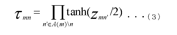
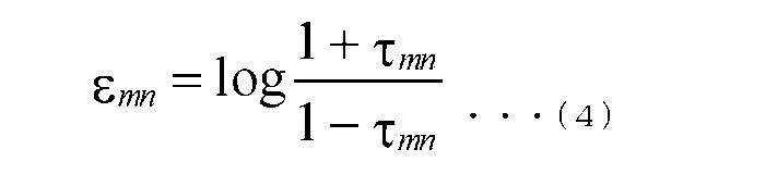


〈1〉ビットが0と与えられている場合、対数尤度比λn=+∞(実際には、正の実数を与える)
〈2〉ビットが1と与えられている場合、対数尤度比λn=-∞(実際には、負の実数を与える)
〈3〉ビットが不定、つまり、消失している場合、対数尤度比λn=0を与え、上記のアルゴリズムにより、消失訂正復号が実施されることになる。
受信時の各ビットがynである場合について説明する(nは1以上N以下の整数である。(Nは2以上の整数である))。ただし、ynは0、1、不定のいずれかである。このとき、受信語y=(y1、y2、y3、・・・、yn-1、yn)であり、パリティ検査行列がH(M行N列)である場合、HyT=0が成立する(ただし、「0」は、要素が0で構成されるベクトル(ゼロベクトル)である)(yTはyの転置ベクトルである)。


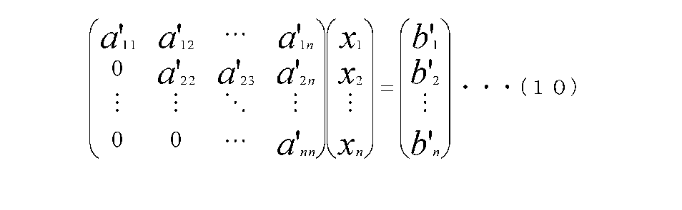
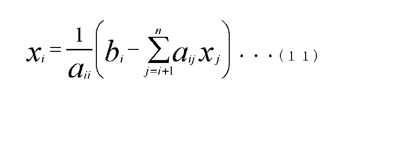
誤り(消失)訂正能力では、最尤復号を用いたときの特性は、BP復号を用いたときの特性より優れている。一方、演算規模では、BP復号の演算規模は、最尤復号の演算規模より小さい。以上を考慮すると、復号方法は、誤り(消失)訂正能力が高く、演算規模が小さい方法によって実現さることが望まれる。
また、各受信装置(端末)は、復号に関する設定画面を表示することで、端末個別に復号方法の設定を行えるようにしてもよい。以下では、その設定方法について説明する。
次に、バッテリーの残量を確認する(S2005)。バッテリーの残量が充分でない場合(S2005:NO)、受信装置(端末)は、「BP復号を行わずパケット(または、データ)を出力」する。バッテリーの残量が充分な場合(S2005:YES)、受信装置(端末)は、「BP復号を行い、パケット(または、データ)を出力」する。受信装置(端末)は、図14、図15、図16、図17に示したように、BP復号が必要のないケースでは、BP復号を省略する。
次に、受信装置(端末)は、(信号)処理能力を確認する(S2003)。例えば、受信装置(端末)は、テストプログラムを実行する。なお、テストプログラムの実行による処理能力の確認は、本明細書のいずれの場合についても実施可能である。
受信装置(端末)は、「BP復号を行わずにパケット(または、データ)を出力」する。なお、受信装置(端末)は、ガウスの消去法を用いた復号も省略する。
受信装置(端末)は、バッテリーの残量を確認する(S2006)。バッテリーの残量が不充分である場合(S2006:NO)、受信装置(端末)は、「BP復号を行わずパケット(または、データ)を出力」する。
受信装置(端末)は、バッテリーの残量を確認する。バッテリーの残量が少ない場合(S2004:小)、受信装置(端末)は、「BP復号を行わずパケット(または、データ)を出力」する。
ところで、図12の変形例として、図21のように、制御部1207は、データ1201、BP復号後の受信系列1203、最尤復号後の受信系列1205を入力とし、各復号後および消失訂正前のデータの、パケットの誤り(消失)の状態により、復号方法の変更を促すような表示を行ってもよい。
本実施の形態では、実施の形態1で説明したパケットレベルの符号化とパケットレベルの復号化の変形例について説明する。
本実施の形態では、実施の形態1、実施の形態2で説明したパケットレベルの誤り(消失)訂正符号化方法を適用するパケットとパケットレベルの誤り(消失)訂正符号化を未適用のパケット(または、情報)とが存在する送信方法の例について説明する。
本実施の形態では、実施の形態1、実施の形態2で説明したパケットレベルの誤り(消失)訂正符号化方法を、中継器で使用する方法の一例について説明する。
図35の中継器3302の受信装置3403におけるパケット(またはフレーム)処理部315は、パケットレベルの誤り(消失)訂正復号を施すことによって、図37の「情報パケットk-#1」から「情報パケットk-#n」のn個の情報パケットを、データ316として、出力する。ただし、データ316は、パケットレベルの誤り(消失)訂正復号の結果次第では、「情報パケットk-#1」から「情報パケットk-#n」のn個の情報パケットの中に、不定の情報パケットを含む。つまり、データ316は、消失訂正復号しても得られなかった情報パケットを含む。
図35の中継器3302の受信装置3403におけるパケット(またはフレーム)処理部315は、パケットレベルの誤り(消失)訂正復号を施すことによって、図37の「情報パケットk-#1」から「情報パケットk-#n」のn個の情報パケット、および、「パリティパケットk-#1」から「パリティパケットk-#h」のh個のパリティパケットを、データ316として、出力する。ただし、データ316は、パケットレベルの誤り(消失)訂正復号の結果次第では、情報パケットk-#1」から「情報パケットk-#n」のn個の情報パケットの中に、不定の情報パケットが存在することもある。つまり、データ316は、消失訂正復号しても得られなかった情報パケットを含む場合がある。また、「パリティパケットk-#1」から「パリティパケットk-#h」のh個のパリティパケットの中には、不定のパリティパケットが存在することもあるし、消失訂正復号しても得られなかったパリティパケットが存在することがある。
図35の中継器3302の受信装置3403におけるパケット(またはフレーム)処理部315は、パケットレベルの誤り(消失)訂正復号を省略する。
本実施の形態では、実施の形態1、実施の形態2で説明したパケットレベルの誤り(消失)訂正符号化方法を、中継器3302で使用する方法について、実施の形態4と異なる例について説明する。
図35の中継器3302の受信装置3403におけるパケット(またはフレーム)処理部315は、パケットレベルの誤り(消失)訂正復号を施すことによって、図39の(B)の「パケットk-#1」から「パケットk-#g」のg個のパケットを得、その後、図39の(A)の「情報パケットk-#1」から「情報パケットk-#n」のn個の情報パケットを、データ316として、出力する。ただし、データ316は、パケットレベルの誤り(消失)訂正復号の結果次第では、「情報パケットk-#1」から「情報パケットk-#n」のn個の情報パケットの中に、不定の情報パケットを含む。つまり、データ316は、消失訂正復号しても得られなかった情報パケットを含む。
図35の中継器3302の受信装置3403におけるパケット(またはフレーム)処理部315は、パケットレベルの誤り(消失)訂正復号を施すことによって、図39の(B)に示す「パケットk-#1」から「パケットk-#g」のg個のパケットを、データ316として、出力する。ただし、データ316は、パケットレベルの誤り(消失)訂正復号の結果次第では、「パケットk-#1」から「パケットk-#g」のg個のパケットの中に、不定のパケットが存在することもある。つまり、データ316は、消失訂正復号しても得られなかったパケットを含む場合がある。
図35の中継器3302の受信装置3403におけるパケット(またはフレーム)処理部315は、パケットレベルの誤り(消失)訂正復号を省略する。
本実施の形態では、本明細書で記載した消失訂正復号(パケットレベルでの消失訂正復号器及びアプリケーションレイヤーでの消失訂正復号の少なくとも一方)の機能をソフトウェアで実現した場合、ソフトウェアを提供する方法の例を、図41を用いて説明する。
当然であるが、本明細書において説明した実施の形態、その他の内容を複数組み合わせて、実施してもよい。
102A,102B,102Z,3303 端末
202,315 パケット(またはフレーム)処理部
204 物理層誤り訂正符号化部
206 変調部
208 送信部
210,301 アンテナ
303 受信部
305 時間及び周波数同期部
307 チャネル推定部
309 制御情報抽出部
311 復調部
313 物理層誤り訂正復号部
318 解析部
321,1207 制御部
382 デコーダ
384 表示部
386 スピーカ
402,506 パケット生成部
404,503 並び替え部
406,504 符号化部
408,410,508,804,812 誤り検出符号付加部
412 パケット並び替え部
802,814 制御情報付加部
1002 誤り検出部
1004 記憶および並び替え部
1006 パケットレベル復号部
1202 BP復号部
1204 最尤復号部
1209 選択部
2202 パラレル-シリアル変換部
2401 ストリーム選択部
3302 中継器
3403 受信装置
3407 送信装置
Claims (1)
- 入力信号に対してBP復号を行うBP復号部と、
前記BP復号された信号に対して、最尤復号を行う最尤復号部と、
前記入力信号、前記BP復号された信号、前記最尤復号された信号のいずれかを選択する選択部と、
を含む、復号装置。
Priority Applications (6)
| Application Number | Priority Date | Filing Date | Title |
|---|---|---|---|
| CN201680003690.3A CN107005253B (zh) | 2015-02-10 | 2016-02-04 | 一种解码装置 |
| JP2016574661A JP6660565B2 (ja) | 2015-02-10 | 2016-02-04 | 復号装置 |
| CA2970901A CA2970901A1 (en) | 2015-02-10 | 2016-02-04 | Transmission method, transmission device, reception method, and reception device |
| EP16748903.8A EP3258605A4 (en) | 2015-02-10 | 2016-02-04 | Transmitting method, transmitting device, receiving method and receiving device |
| US15/618,404 US10326554B2 (en) | 2015-02-10 | 2017-06-09 | Transmission method, transmission device, reception method, and reception device |
| US16/391,939 US10700811B2 (en) | 2015-02-10 | 2019-04-23 | Transmission method, transmission device, reception method, and reception device |
Applications Claiming Priority (4)
| Application Number | Priority Date | Filing Date | Title |
|---|---|---|---|
| JP2015024242 | 2015-02-10 | ||
| JP2015-024242 | 2015-02-10 | ||
| JP2015139840 | 2015-07-13 | ||
| JP2015-139840 | 2015-07-13 |
Related Child Applications (1)
| Application Number | Title | Priority Date | Filing Date |
|---|---|---|---|
| US15/618,404 Continuation US10326554B2 (en) | 2015-02-10 | 2017-06-09 | Transmission method, transmission device, reception method, and reception device |
Publications (1)
| Publication Number | Publication Date |
|---|---|
| WO2016129256A1 true WO2016129256A1 (ja) | 2016-08-18 |
Family
ID=56614298
Family Applications (1)
| Application Number | Title | Priority Date | Filing Date |
|---|---|---|---|
| PCT/JP2016/000574 WO2016129256A1 (ja) | 2015-02-10 | 2016-02-04 | 送信方法、送信装置、受信方法、受信装置 |
Country Status (6)
| Country | Link |
|---|---|
| US (2) | US10326554B2 (ja) |
| EP (1) | EP3258605A4 (ja) |
| JP (1) | JP6660565B2 (ja) |
| CN (1) | CN107005253B (ja) |
| CA (1) | CA2970901A1 (ja) |
| WO (1) | WO2016129256A1 (ja) |
Cited By (1)
| Publication number | Priority date | Publication date | Assignee | Title |
|---|---|---|---|---|
| JP2021519037A (ja) * | 2018-04-20 | 2021-08-05 | フラウンホーファー−ゲゼルシャフト・ツール・フェルデルング・デル・アンゲヴァンテン・フォルシュング・アインゲトラーゲネル・フェライン | 無線伝送システムのためのパケット検出器/デコーダ |
Families Citing this family (3)
| Publication number | Priority date | Publication date | Assignee | Title |
|---|---|---|---|---|
| US10396826B2 (en) * | 2016-10-26 | 2019-08-27 | Huawei Technologies Co., Ltd. | Software defined network with selectable low latency or high throughput mode |
| KR102576075B1 (ko) * | 2018-05-15 | 2023-09-07 | 삼성전자주식회사 | 무선 통신 시스템에서 재전송을 수행하기 위한 장치 및 방법 |
| CN113381838A (zh) * | 2020-03-09 | 2021-09-10 | 华为技术有限公司 | 数据传输方法及通信装置 |
Citations (3)
| Publication number | Priority date | Publication date | Assignee | Title |
|---|---|---|---|---|
| JP2008527948A (ja) * | 2005-01-19 | 2008-07-24 | クゥアルコム・インコーポレイテッド | 符号化伝送のための節電方法 |
| JP2010178328A (ja) * | 2009-01-27 | 2010-08-12 | Mitsubishi Electric Research Laboratories Inc | シンボルから成るブロックを復号するための多段復号器及び方法 |
| JP2012039450A (ja) * | 2010-08-09 | 2012-02-23 | Jvc Kenwood Corp | 復号装置および復号方法 |
Family Cites Families (12)
| Publication number | Priority date | Publication date | Assignee | Title |
|---|---|---|---|---|
| US8001452B2 (en) * | 2006-11-17 | 2011-08-16 | Agere Systems Inc. | Methods and apparatus for soft decision decoding using reliability values based on a log base two function |
| JP4743156B2 (ja) * | 2007-04-27 | 2011-08-10 | ソニー株式会社 | 復号装置 |
| JP5318091B2 (ja) * | 2008-04-18 | 2013-10-16 | シャープ株式会社 | 受信装置および通信システム |
| US8286048B1 (en) * | 2008-12-30 | 2012-10-09 | Qualcomm Atheros, Inc. | Dynamically scaled LLR for an LDPC decoder |
| JP4843060B2 (ja) | 2009-02-05 | 2011-12-21 | 株式会社スクウェア・エニックス | ゲーム装置、ゲームキャラクタの表示方法、ゲームプログラム及び記録媒体 |
| CN102130695B (zh) * | 2010-01-15 | 2013-06-12 | 中兴通讯股份有限公司 | 一种级联码的译码方法及装置 |
| JP5578618B2 (ja) | 2010-11-08 | 2014-08-27 | パナソニック インテレクチュアル プロパティ コーポレーション オブ アメリカ | 送信方法、送信装置、受信方法および受信装置 |
| JP5578619B2 (ja) | 2010-12-10 | 2014-08-27 | パナソニック インテレクチュアル プロパティ コーポレーション オブ アメリカ | 送信装置および受信装置 |
| US9214962B2 (en) * | 2011-07-27 | 2015-12-15 | Panasonic Intellectual Property Corporation Of America | Encoding method, decoding method |
| US20140214967A1 (en) | 2011-08-26 | 2014-07-31 | Nippon Hoso Kyokai | Receiver and reception method |
| CN102594367B (zh) * | 2012-02-29 | 2015-03-25 | 中山大学 | 一种ldpc码的低复杂度的动态异步bp译码方法 |
| CN106160831B (zh) * | 2015-03-23 | 2019-09-17 | 电信科学技术研究院 | 一种信号检测方法及装置 |
-
2016
- 2016-02-04 CN CN201680003690.3A patent/CN107005253B/zh not_active Expired - Fee Related
- 2016-02-04 CA CA2970901A patent/CA2970901A1/en not_active Abandoned
- 2016-02-04 JP JP2016574661A patent/JP6660565B2/ja active Active
- 2016-02-04 WO PCT/JP2016/000574 patent/WO2016129256A1/ja active Application Filing
- 2016-02-04 EP EP16748903.8A patent/EP3258605A4/en not_active Ceased
-
2017
- 2017-06-09 US US15/618,404 patent/US10326554B2/en active Active
-
2019
- 2019-04-23 US US16/391,939 patent/US10700811B2/en active Active
Patent Citations (3)
| Publication number | Priority date | Publication date | Assignee | Title |
|---|---|---|---|---|
| JP2008527948A (ja) * | 2005-01-19 | 2008-07-24 | クゥアルコム・インコーポレイテッド | 符号化伝送のための節電方法 |
| JP2010178328A (ja) * | 2009-01-27 | 2010-08-12 | Mitsubishi Electric Research Laboratories Inc | シンボルから成るブロックを復号するための多段復号器及び方法 |
| JP2012039450A (ja) * | 2010-08-09 | 2012-02-23 | Jvc Kenwood Corp | 復号装置および復号方法 |
Non-Patent Citations (2)
| Title |
|---|
| KUNITAKA MUROTSU ET AL.: "An Erasure Correction Scheme based on BP and Gaussian Elimination", THE 27TH SYMPOSIUM ON INFORMATION THEORY AND ITS APPLICATIONS YOKOSHU, 14 December 2004 (2004-12-14), pages 271 - 274, XP008182436 * |
| See also references of EP3258605A4 * |
Cited By (3)
| Publication number | Priority date | Publication date | Assignee | Title |
|---|---|---|---|---|
| JP2021519037A (ja) * | 2018-04-20 | 2021-08-05 | フラウンホーファー−ゲゼルシャフト・ツール・フェルデルング・デル・アンゲヴァンテン・フォルシュング・アインゲトラーゲネル・フェライン | 無線伝送システムのためのパケット検出器/デコーダ |
| JP7058756B2 (ja) | 2018-04-20 | 2022-04-22 | フラウンホーファー-ゲゼルシャフト・ツール・フェルデルング・デル・アンゲヴァンテン・フォルシュング・アインゲトラーゲネル・フェライン | 無線伝送システムのためのパケット検出器/デコーダ |
| US11483015B2 (en) | 2018-04-20 | 2022-10-25 | Fraunhofer-Gesellschaft zur Förderung der angewandten Forschung e.V. | Packet detector/decoder for a radio transmission system |
Also Published As
| Publication number | Publication date |
|---|---|
| CN107005253B (zh) | 2020-05-19 |
| US10326554B2 (en) | 2019-06-18 |
| EP3258605A4 (en) | 2018-03-28 |
| JPWO2016129256A1 (ja) | 2017-11-30 |
| CN107005253A (zh) | 2017-08-01 |
| US20170279560A1 (en) | 2017-09-28 |
| US20190253189A1 (en) | 2019-08-15 |
| EP3258605A1 (en) | 2017-12-20 |
| JP6660565B2 (ja) | 2020-03-11 |
| US10700811B2 (en) | 2020-06-30 |
| CA2970901A1 (en) | 2016-08-18 |
Similar Documents
| Publication | Publication Date | Title |
|---|---|---|
| JP4875088B2 (ja) | 多入力多出力チャンネルのための低密度パリティ検査コード用のコード設計及び構造の改良 | |
| US10680750B2 (en) | Transmitting apparatus and mapping method thereof | |
| US10680735B2 (en) | Transmitting apparatus and mapping method thereof | |
| US9912356B2 (en) | Transmitting apparatus and mapping method thereof | |
| US10700811B2 (en) | Transmission method, transmission device, reception method, and reception device | |
| US10554336B2 (en) | Transmitting apparatus and non-uniform constellation mapping method thereof | |
| US11082064B2 (en) | Transmitting apparatus and mapping method thereof | |
| US9602232B2 (en) | Transmitting apparatus and mapping method thereof | |
| US11082278B2 (en) | Transmitting apparatus and mapping method thereof | |
| KR100886075B1 (ko) | 방송 시스템에서 복수의 정보 비트를 포함한 데이터를인코딩하는데 이용되는 저밀도 패리티 검사 코드를설계하기 위한 방법 및 시스템 | |
| US11133972B2 (en) | Transmitting apparatus and mapping method thereof | |
| WO2015174053A1 (ja) | 送信方法、受信方法、送信装置および受信装置 | |
| US20210119731A1 (en) | Transmitting apparatus and mapping method thereof | |
| US20170338904A1 (en) | Transmitting apparatus and mapping method thereof |
Legal Events
| Date | Code | Title | Description |
|---|---|---|---|
| 121 | Ep: the epo has been informed by wipo that ep was designated in this application |
Ref document number: 16748903 Country of ref document: EP Kind code of ref document: A1 |
|
| ENP | Entry into the national phase |
Ref document number: 2016574661 Country of ref document: JP Kind code of ref document: A |
|
| ENP | Entry into the national phase |
Ref document number: 2970901 Country of ref document: CA |
|
| REEP | Request for entry into the european phase |
Ref document number: 2016748903 Country of ref document: EP |
|
| NENP | Non-entry into the national phase |
Ref country code: DE |