WO2016125637A1 - 筒内圧検出装置 - Google Patents
筒内圧検出装置 Download PDFInfo
- Publication number
- WO2016125637A1 WO2016125637A1 PCT/JP2016/052222 JP2016052222W WO2016125637A1 WO 2016125637 A1 WO2016125637 A1 WO 2016125637A1 JP 2016052222 W JP2016052222 W JP 2016052222W WO 2016125637 A1 WO2016125637 A1 WO 2016125637A1
- Authority
- WO
- WIPO (PCT)
- Prior art keywords
- cylinder pressure
- fuel injection
- connector portion
- injection device
- pressure detection
- Prior art date
- Legal status (The legal status is an assumption and is not a legal conclusion. Google has not performed a legal analysis and makes no representation as to the accuracy of the status listed.)
- Ceased
Links
Images





Classifications
-
- F—MECHANICAL ENGINEERING; LIGHTING; HEATING; WEAPONS; BLASTING
- F02—COMBUSTION ENGINES; HOT-GAS OR COMBUSTION-PRODUCT ENGINE PLANTS
- F02M—SUPPLYING COMBUSTION ENGINES IN GENERAL WITH COMBUSTIBLE MIXTURES OR CONSTITUENTS THEREOF
- F02M57/00—Fuel-injectors combined or associated with other devices
-
- G—PHYSICS
- G01—MEASURING; TESTING
- G01L—MEASURING FORCE, STRESS, TORQUE, WORK, MECHANICAL POWER, MECHANICAL EFFICIENCY, OR FLUID PRESSURE
- G01L23/00—Devices or apparatus for measuring or indicating or recording rapid changes, such as oscillations, in the pressure of steam, gas, or liquid; Indicators for determining work or energy of steam, internal-combustion, or other fluid-pressure engines from the condition of the working fluid
- G01L23/08—Devices or apparatus for measuring or indicating or recording rapid changes, such as oscillations, in the pressure of steam, gas, or liquid; Indicators for determining work or energy of steam, internal-combustion, or other fluid-pressure engines from the condition of the working fluid operated electrically
-
- G—PHYSICS
- G01—MEASURING; TESTING
- G01L—MEASURING FORCE, STRESS, TORQUE, WORK, MECHANICAL POWER, MECHANICAL EFFICIENCY, OR FLUID PRESSURE
- G01L23/00—Devices or apparatus for measuring or indicating or recording rapid changes, such as oscillations, in the pressure of steam, gas, or liquid; Indicators for determining work or energy of steam, internal-combustion, or other fluid-pressure engines from the condition of the working fluid
- G01L23/22—Devices or apparatus for measuring or indicating or recording rapid changes, such as oscillations, in the pressure of steam, gas, or liquid; Indicators for determining work or energy of steam, internal-combustion, or other fluid-pressure engines from the condition of the working fluid for detecting or indicating knocks in internal-combustion engines; Units comprising pressure-sensitive members combined with ignitors for firing internal-combustion engines
Definitions
- the present invention relates to an in-cylinder pressure detecting device that detects an in-cylinder pressure that is a pressure in a combustion chamber of an internal combustion engine, and in particular, an in-cylinder pressure detection that includes a pressure detecting element mounted at a tip of a fuel injection device that injects fuel into the combustion chamber. Relates to the device.
- Patent Document 1 includes a pressure detection element attached to an ignition plug or a fuel injection valve of an internal combustion engine, and an amplification circuit (charge amplifier) that amplifies a voltage change of the pressure detection element and outputs a pressure detection signal.
- a combustion pressure sensor is shown.
- the pressure detection element is fixed to the outside of the combustion chamber integrally with the fuel injection valve by, for example, a nut to which the fuel injection valve is attached, and the amplification circuit is integrated with the sensor fixing portion to which the pressure detection element is fixed. Provided.
- Patent Document 2 discloses an in-cylinder pressure detecting device in which a pressure detecting element is attached to a tip of a fuel injection valve that injects fuel into a combustion chamber and the in-cylinder pressure is detected using the pressure detecting element.
- Patent Document 1 requires room for improvement in terms of workability at the time of mounting because the sensor fixing portion needs to be sandwiched and fixed at the same time when the fuel injection valve is fixed. .
- Patent Document 2 when the pressure detection element is disposed at the tip of the portion of the fuel injection valve that is inserted into the combustion chamber, the pressure detection element and the amplification circuit are disposed close to each other. It has been desired to realize the above with good workability.
- a pressure detection element is attached to the tip of the fuel injection device (fuel injection valve) to detect the in-cylinder pressure, and to influence the drive signal of the fuel injection device.
- An object of the present invention is to provide an in-cylinder pressure detecting device that can reduce and improve workability when mounted on an internal combustion engine.
- the present invention provides a pressure detection element (2) attached to the tip of a fuel injection device (1) for injecting fuel into a combustion chamber of an internal combustion engine, and a signal output from the pressure detection element.
- an amplifier circuit unit (81) including an amplifier circuit for amplifying the pressure and outputting a pressure detection signal, and providing an in-cylinder pressure detecting device for detecting the pressure in the combustion chamber.
- an in-cylinder pressure detecting unit (201) including the pressure detecting element (2), the amplifying circuit unit (81), and a connecting member (12) for connecting the pressure detecting element and the amplifying circuit unit.
- the fuel injection device (1) has a main body connector portion having detection signal line connection terminals (71 to 73) to which a detection signal line for supplying the pressure detection signal to a control unit that controls the fuel injection device is connected.
- the in-cylinder pressure detection unit (201) is configured integrally with the amplification circuit unit (81), and can be coupled by fitting into the main body connector portion (70). Is provided.
- the sub-connector portion has sub-connecting terminals (91 to 93) for transmitting the pressure detection signal to the main body connector portion, and couples the sub-connector portion (82) to the main body connector portion (70). Accordingly, the sub connection terminals (91 to 93) are configured to come into contact with the detection signal line connection terminals (71 to 73).
- the in-cylinder pressure detection unit with the in-cylinder pressure detection unit is configured by integrating the in-cylinder pressure detection unit including the pressure detection element, the amplification circuit unit, and the connecting member that connects them with the fuel injection device.
- the fuel injection device with the in-cylinder pressure detection unit is mounted on the internal combustion engine. Therefore, the influence of the drive signal of the fuel injection device can be reduced, and the workability when the pressure detection element and the amplification circuit unit are integrated with the fuel injection device and mounted on the internal combustion engine can be improved.
- the amplification circuit unit of the in-cylinder pressure detection unit is fixed to the fuel injection device, and the sub connection terminal and the detection signal line connection terminal are in contact with each other. And the detection signal line connection terminal can be easily performed.
- the main body connector portion (70) has a terminal receiving recess (70) in which the detection signal line connecting terminals (71 to 73) are exposed and the sub connecting terminals (91 to 93) of the sub connector portion (82) are received. 74), and the sub connection terminals (91 to 93) are connected to the detection signal line connection terminals (71 to 73) in the terminal accommodating recess, and the terminal accommodating recess is filled with an adhesive.
- the sub connection terminal of the sub connector portion is connected to the detection signal line connection terminal of the main body connector portion in the terminal accommodating recess of the main body connector portion, and the terminal accommodating recess is filled with the adhesive. It is possible to reliably prevent water from entering the connection portion between the connection terminal and the detection signal line connection terminal.
- an auxiliary member (76) for preventing leakage of the adhesive is interposed in a joint portion between the sub-connector portion (82) and the main body connector portion (70). Since there may be a gap in the joint between the sub-connector part and the main body connector part, it is possible to prevent the adhesive before solidifying from leaking through the gap by providing an auxiliary member.
- the connecting member (12) for connecting the pressure detection element and the amplification circuit unit, the amplification circuit unit (81), and the terminal accommodating recess (74) are arranged so that the in-cylinder pressure detection unit (201) After being integrated with the fuel injection device (1), it is covered with a molding material (202).
- the main part of the in-cylinder pressure detection unit is covered with the molding material, so that it is easy to handle in an integrated state with the fuel injection device, and the effects of waterproofing, heat insulation, and insulation of the amplifier circuit unit are achieved. Can be definitely obtained.
- the amplification circuit unit (81) is sealed with a heat resistant resin (81a).
- the amplification circuit unit When the coating with the molding material is finally performed, the amplification circuit unit is exposed to a relatively high temperature for a certain period of time. Therefore, the heat resistance can be increased by sealing with a heat resistant resin.
- the in-cylinder pressure detection unit (201) includes a cylindrical sensor fixing member (13) in which the pressure detection element (2) is fixed to a tip portion, the amplification circuit unit (81), and the pressure detection.
- the sensor fixing member (13) is fitted into the front end portion of the fuel injection device.
- the sensor fixing member (13) is assembled by previously assembling a connection member (12) for connecting the element and the amplifier circuit unit.
- the in-cylinder pressure detection unit is configured by assembling in advance the sensor fixing member, the amplification circuit unit, and the connection member that connects them, and the in-cylinder pressure detection unit is a cylindrical shape to which the pressure detection element is fixed.
- the fuel injection device with the in-cylinder pressure detection unit is configured, so that the workability when integrating the in-cylinder pressure detection unit with the fuel injection device can be improved. it can.
- the main body connector portion has a drive signal line connection terminal to which a drive signal line for supplying a drive signal of the fuel injection device from the control unit is connected.
- the main body connector portion includes the drive signal line connection terminal as well as the detection signal connection terminal, it is possible to improve workability when connecting the connection line from the control unit to the fuel injection device.
- FIG. 6 is a diagram for explaining a mounting state of a connection member (12) and a diagram for explaining connection of connector pins (91 to 93, 71 to 73).
- connection member (12) shown in FIG. It is a figure for demonstrating the structure of the connection member (12) shown in FIG. It is sectional drawing which shows the structure of the front-end
- FIG. 1A is a side view of a fuel injection device with an in-cylinder pressure detection unit of the present embodiment
- FIG. 1B is a state where the fuel injection device shown in FIG. 1A is covered with a synthetic resin mold.
- FIG. 1C is a diagram for explaining the main body connector 70 viewed from the direction of arrow B in FIG.
- FIG. 1A shows a state where there is no synthetic resin mold for the sake of explanation (however, the amplification circuit unit 81 is sealed and formed with a synthetic resin mold 81a).
- 2 (a) to 2 (d) show a state in which the fuel injection device 1 and the in-cylinder pressure detection unit 201 are being attached, a state in which the in-cylinder pressure detection unit 201 is attached, and an in-cylinder pressure detection unit 201, respectively.
- 3 shows the final form covered with the synthetic resin mold 202, that is, the fuel injection device 200 with an in-cylinder pressure detection unit.
- the in-cylinder pressure detection unit 201 is attached to the fuel injection device 1 by moving in the direction indicated by the arrow C.
- the fuel injection device 1 is a device that injects fuel into a combustion chamber of an internal combustion engine. Inside the valve body, which is a well-known component, a solenoid (drive circuit) that drives the valve body, a spring that biases the valve body, and the like The fuel is injected from the injection port 5 at the tip.
- the fuel injection device 1 includes a metal large-diameter portion casing 3 in which a solenoid is incorporated, and a metal small-diameter portion casing 4 provided with an injection port 5 at the tip.
- the in-cylinder pressure detection unit 201 connects the pressure detection element 2, the cylindrical sensor fixing member 13 with the pressure detection element 2 fixed to the tip, the amplification circuit unit 81, and the pressure detection element 2 and the amplification circuit unit 81.
- the in-cylinder pressure detection unit 201 is made to be fuel by inserting the sensor fixing member 13 into the distal end side (injection port 5 side) of the small diameter casing 4 of the fuel injection device 1. Mounted on the injection device 1. Therefore, the pressure detection element 2 is attached to the tip of the fuel injection device 1 (a position surrounding the injection port 5), and is connected to the amplifier circuit unit 81 by the connection member 12.
- the amplifier circuit unit 81 is coated (sealed) with a heat-resistant synthetic resin mold 81a.
- the sub-connector pins 91 to 93 are fixed to the amplifier circuit unit 81, and the sub-connector portion 82 including the sub-connector pins 91 to 93 is formed by the synthetic resin mold 81a.
- the fuel injection device 1 is fixed with a main body connector portion 70 which is constituted by a part of the synthetic resin mold 203 and to which a connection line from an electronic control unit (hereinafter referred to as “ECU”) 60 (see FIGS. 8 to 9) is connected. Has been.
- the ECU 60 controls the drive of the fuel injection device 1 and detects the in-cylinder pressure by the in-cylinder pressure detection unit 201.
- the main body connector unit 70 includes first connector pins 21 to 23 to which a drive signal line to which a drive signal of the fuel injection device 1 is supplied from the ECU 60, a detection signal line for supplying a pressure detection signal to the ECU 60, and the like ( Second connector pins 71 to 73 to which a power supply connection line (ground connection line) is connected, a terminal receiving recess 74 for connecting the second connector pins 71 to 73 to the sub connector pins 91 to 93, and an in-cylinder pressure detection unit And a holding member 75 for holding the sub-connector portion 82 when the 201 is mounted.
- the second connector pins 71 to 73 are exposed in the terminal accommodating recess 74, and the second connector pins 71 to 73 are configured to be connectable to the sub connector pins 91 to 93.
- An auxiliary member 76 for preventing leakage of the adhesive before being solidified is interposed in a joint portion between the sub connector portion 82 and the main body connector portion 70.
- a connector member (not shown) that can be fitted to the first connector pins 21 to 23 and the second connector pins 71 to 73 of the main body connector portion 70 is fixed to the distal end portion of the connection line from the ECU 60, and the connector member is By fitting, the connection line and each of the connector pins 21 to 23 and 71 to 73 are connected.
- the amplifier circuit unit 81 covered with the synthetic resin mold 81a, the connection member 12, and A part of the sensor fixing member 13 (side closer to the amplification circuit unit 81) is covered with the synthetic resin mold 202.
- the sub connector pins 91 to 93 are connected to the second connector pins 71 to 73, respectively. Resistance welding is performed, and the terminal accommodating recess 74 is filled with a waterproofing adhesive (for example, a silicon adhesive).
- the portion indicated by the right-down hatching corresponds to the synthetic resin mold 203 constituting the main body connector portion 70 of the fuel injection device 1 shown in FIG. 2 (a).
- the portion indicated by is equivalent to the last synthetic resin mold 202 shown in FIG.
- FIG. 3 is a perspective view for explaining the connection between the sub connector pins 91 to 93 and the second connector pins 71 to 73 in more detail.
- FIG. 3A shows the sub connector portion 82 and the main body connector portion.
- FIG. 7B shows a state where the connection is completed, and
- FIG. 5C shows a state where the adhesive 77 is filled after the resistance welding of the connector pin is completed.
- auxiliary member 76 is interposed between the sub-connector portion 82 and the main body connector portion 70, and the sub-connector portion 82 is sandwiched between the two holding members 75 of the main body connector portion 70 by being pushed rightward in the drawing. It is fixed ((b) in the figure).
- the terminal accommodating recess 74, the sub connector portion 82, and the auxiliary member 76 form a storage portion capable of storing the adhesive before solidification, and the auxiliary member 76 is By interposing, leakage of the adhesive before solidifying from the coupling portion is prevented.
- FIG. 4 is a diagram for explaining in detail the structure of a synthetic resin mold 81a that covers the amplifier circuit unit 81 and forms the sub-connector portion 82.
- FIGS. 4 (a) to (d) are respectively a synthetic resin mold.
- 81a (including sub-connector pins 91 to 93) is a perspective view, a plan view, a front view, and a side view, and a plan view of the auxiliary member 76 is also shown in the plan view (b).
- the synthetic resin mold 81a forms a sub-connector portion 82 for holding the sub-connector pins 91 to 93, a bottom surface 83 that is curved so as to be in close contact with the outer peripheral surface of the large-diameter casing 3 of the fuel injection device 1, and a fixing protrusion. 84.
- the fixing projection 84 is fitted into a fixing recess (not shown) provided in the large diameter casing 3, and the synthetic resin mold 81 a is fixed on the large diameter casing 3.
- the sub-connector portion 82 is formed with a taper portion 85, and when the sub-connector portion 82 is coupled to the main body connector portion 70, the sub-connector portion 82 is smoothly interposed between the two holding members 75. It becomes possible to fit in.
- the auxiliary member 76 has notches 76a, 76b, and 76c corresponding to the sub connector pins 91 to 93.
- the sub connector pins 91 to 93 are cut. It is configured to pass through the notches 76a, 76b, and 76c.
- FIG. 5A is a diagram for explaining a mounting state of the connection member 12, and the connection member 12 connected to the amplifier circuit unit 81 is mounted so as to be in contact with the large-diameter casing 3 as much as possible. . This prevents the connection member 12 from being peeled off (raised) when finally covering the synthetic resin mold 202.
- FIG. 5B is a diagram for explaining the connection between the sub connector pins 91 to 93 and the second connector pins 71 to 73.
- the sub connector 82 When the sub connector 82 is coupled to the main body connector 70, the sub connector The pins 91 (92, 93) are in contact with the second connector pins 71 (72, 73) in the terminal accommodating recess 74. And both are connected by carrying out resistance welding of this contact part (it shows with the ellipse PW of a broken line).
- the auxiliary member 76 is interposed between the sub-connector portion 82 and the main body connector portion 70, and is fixed at the position shown in this figure.
- FIG. 6A and 6B are diagrams for explaining the structure of the connecting member 12, in which FIG. 6A is a plan view and FIG. 6B is a cross-sectional view taken along the line AA in FIG. 6A.
- the connecting member 12 has a structure known as a flexible wiring board configured by covering the copper wire 17 with the polyimide covering members 14 and 15 via the adhesive 16 (epoxy resin), and is disconnected. And can be bent easily.
- the connection member 12 is connected to the pressure detection element 2 in the vicinity of the distal end (the portion indicated by RIN in FIG. 6A) passes through the inside of the metal sensor fixing member 13 as shown in FIG. Between the vicinity portion RIN and the amplification circuit unit 81, the fuel injection device 1 is disposed along the outer peripheral surface of the large-diameter casing 3.
- FIG. 8 is a block diagram showing the configuration of the amplifier circuit unit 81.
- the amplifier circuit unit 81 includes a capacitor 41, a low-pass filter 42, a charge amplifier 43, a high-pass filter 44, an amplifier circuit 45, a sensitivity adjustment circuit 46, and a failure detection circuit. 47, a reference voltage circuit 48, a power supply noise filter 49, an AC grounding capacitor 50, and subconnector pins 91 to 93 constituting a subconnector portion 82.
- the sub connector pin 91 is connected to the ground of the ECU 60 via the main body connector portion 70 (connector pin 71) and the ground connection wire 61, and the main connector portion 70 (connector pin 72) and the power supply connection wire 62 are connected to the sub connector pin 92.
- a DC power supply voltage (for example, 5 V) is supplied via the connector, and the sub connector pin 93 is connected to the AD converter of the ECU 60 via the main body connector portion 70 (connector pin 73) and the signal connection line (detection signal line) 63. Is done.
- the power supply line 53 connected to the sub connector pin 92 is connected to the reference voltage circuit 48 via the power supply noise filter 49.
- the capacitor 41 cuts the DC component of the input detection signal from the pressure detection element 2 through the connection member 12, and only the AC component of the input detection signal is input to the low-pass filter 42.
- the low pass filter 42 attenuates unnecessary high frequency components.
- the charge amplifier 43 converts the input signal indicating the pressure change rate into a pressure signal indicating the pressure value by amplifying the input signal while integrating the input signal.
- the high pass filter 44 attenuates unnecessary low frequency components.
- the amplifier circuit 45 amplifies the output signal of the high pass filter 44.
- the sensitivity adjustment circuit 46 is composed of, for example, a combination of a plurality of resistance elements, and the output signal level of the amplification circuit 45 when the pressure detection element 2 is connected and a test pressure is applied to the pressure detection element 2 is predetermined.
- This is a circuit for adjusting the gain of the amplifier circuit 45 so as to be at the level. Specifically, the resistance value as a whole is adjusted by cutting a wiring connecting a plurality of resistance elements mounted in advance, and gain adjustment is performed. This gain adjustment is performed before the amplification circuit unit 81 is covered with the synthetic resin mold 81a.
- the reference voltage circuit 48 generates a reference voltage VREF from the power supply voltage VS1 supplied from the ECU 60 and supplies the reference voltage VREF to the charge amplifier 43, the high-pass filter 44, and the amplifier circuit 45.
- the reference voltage VREF is a voltage for offsetting the DC voltage (raising 0V to 1V).
- the power supply noise filter 49 is a low-pass filter that removes noise mixed through the power supply connection line 62.
- the ground wire 52 of the amplifier circuit unit 81 is connected to the ground of the ECU 60 through the sub connector portion 82, the main body connection portion 70, and the ground connection wire 61, but the housing of the fuel injection device 1 is an AC grounding capacitor. 50, and is not connected to the casing of the fuel injection device 1 in terms of direct current. As a result, the disconnection of the ground connection line 61 can be detected by the ECU 60 as described below. Note that the housing of the fuel injection device 1 is electrically connected to the cylinder head of the internal combustion engine.
- the failure detection circuit 47 is configured by connecting a pull-up resistor RPU to the power supply line LS as shown in FIG.
- the ECU 60 is provided with a pull-down resistor RPD connected to the ground.
- the power connection line 62 or the signal connection line 63 is disconnected or grounded (short-circuited with the ground) or the ground connection line 61 according to the input DC voltage VIN.
- the disconnection is configured to be detectable. That is, when the connection line 62 or 63 is disconnected or a ground fault occurs, the input DC voltage VIN becomes “0”, and when the ground connection line 61 is disconnected, the input DC voltage VIN becomes higher than the normal voltage VNL. Therefore, when the input DC voltage VIN is higher than the normal voltage VNL by a predetermined voltage or higher, it can be determined that the ground connection line 61 is disconnected.
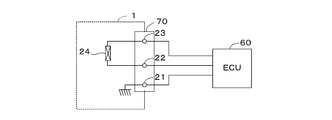
- FIG. 10 is a diagram for explaining the connection between the drive solenoid 24 of the fuel injection device 1 and the ECU 60, and both ends of the solenoid 24 are connected to the ECU 60 via the first connector pins 22 and 23 of the main body connector portion 70.
- the first connector pin 21 is connected to the housing in the fuel injection device 1.
- the in-cylinder pressure detection unit 201 is integrated with the fuel injection device 1 by integrating the in-cylinder pressure detection unit 201 including the pressure detection element 2, the amplifier circuit unit 81, and the connection member 12 connecting them.
- a fuel injection device 200 with a cylinder is configured, and the fuel injection device 200 with an in-cylinder pressure detection unit is mounted on an internal combustion engine. Therefore, the influence of the drive signal of the fuel injection device 1 can be reduced, and the workability when the pressure detection element 2 and the amplification circuit unit 81 are integrated with the fuel injection device 1 and mounted on the internal combustion engine can be improved.
- the amplification circuit unit 81 of the in-cylinder pressure detection unit 201 is fixed to the fuel injection device 1, and the sub-connector pins 91 to 93 and the second connector pins 71 to 73 makes contact with the sub-connector pins 91 to 93 and the second connector pins 71 to 73 with ease.
- the in-cylinder pressure detection unit 201 is configured by assembling in advance the cylindrical sensor fixing member 13 to which the pressure detection element 2 is fixed, the amplification circuit unit 81, and the connection member 12 that connects the pressure detection element 2 and the amplification circuit unit 81. Since the in-cylinder pressure detection unit 201 fits the sensor fixing member 13 into the front end portion of the fuel injection device 1 (the front end side of the small-diameter portion casing 4), the fuel injection device 200 with in-cylinder pressure detection unit is configured. The workability when the in-cylinder pressure detection unit 201 is integrated with the fuel injection device 1 can be improved.
- the sub connector pins 91 to 93 are connected to the second connector pins 71 to 73 in the terminal accommodating recess 74 of the main body connector portion 70, and the terminal accommodating recess 74 is filled with the adhesive 77, so that the sub connector pins 91 to
- auxiliary member 76 for preventing the leakage of the adhesive 77 is interposed at the joint between the sub connector 82 and the main body connector 70, the adhesive before solidifying leaks from the gap between the joints. Can be prevented.
- the main part of the in-cylinder pressure detection unit 201 that is, the amplification circuit unit 81 covered with the synthetic resin mold 81 a, the connection member 12, and a part of the sensor fixing member 13 (part close to the amplification circuit unit 81) are the synthetic resin mold 202. Therefore, handling in an integrated state with the fuel injection device 1 is facilitated, and waterproofing, heat insulation, and insulation effects of the amplifier circuit unit 81 can be reliably obtained.
- the amplification circuit unit 81 is covered (sealed and molded) with the heat-resistant synthetic resin mold 81a, the heat-resistance is increased and finally the synthetic resin mold 202 is fixed at a relatively high temperature. Even if it is exposed to time, it can be avoided reliably.
- the main body connector section 70 includes the first connector pins 21 to 23 to which the drive signal lines are connected together with the second connector pins 71 to 73, so that the workability when connecting the connection lines from the ECU 60 to the fuel injection device 1 is improved. Can be increased.
- the main body connector unit 70 includes the first connector pins 21 to 23 and the second connector pins 71 to 73.
- the main body connector unit 70 includes the first main body connector unit and the second main unit connector unit.
- the main body connector portion is divided into main body connector portions, and the first main body connector portion has connector pins 21 to 23 of the fuel injection device 1, and the second main body connector portion is connected to the sub connector pins 91 to 93 of the amplifier circuit unit 81.
- a configuration having connector pins 71 to 73 may be adopted.
- connection line 63 for transmitting the pressure detection signal is separated from the drive signal line through which a relatively large current flows, and the fuel injection device The influence of the driving signal 1 on the pressure detection signal can be reduced.
- the synthetic resin molds 202 and 203 may be replaced with ceramic molds.
- the sensitivity adjustment circuit 46 of the amplifier circuit unit 81 is configured by a combination of a plurality of resistance elements.
- gain adjustment may be performed by writing gain adjustment data in a nonvolatile memory. Good.
- the amplifier circuit unit 81 may be configured on a glass epoxy resin substrate, and the connection member 12 may be connected to the glass epoxy resin substrate.
Landscapes
- Engineering & Computer Science (AREA)
- Chemical & Material Sciences (AREA)
- Combustion & Propulsion (AREA)
- Physics & Mathematics (AREA)
- General Physics & Mathematics (AREA)
- Mechanical Engineering (AREA)
- General Engineering & Computer Science (AREA)
- Measuring Fluid Pressure (AREA)
- Fuel-Injection Apparatus (AREA)
Abstract
内燃機関の燃焼室内に燃料を噴射する燃料噴射装置の先端部に装着される圧力検出素子と、該圧力検出素子から出力される信号を増幅して圧力検出信号を出力する増幅回路を含む増幅回路ユニットとを備え、燃焼室内の圧力を検出する筒内圧検出装置が提供される。圧力検出素子、増幅回路ユニット、及びこれらを接続する接続部材を含む筒内圧検出ユニットを燃料噴射装置と一体化することによって、筒内圧検出ユニット付き燃料噴射装置が構成される。燃料噴射装置は、圧力検出信号を出力するための検出信号線が接続される検出信号線接続端子を有する本体コネクタ部を備え、筒内圧検出ユニットは、本体コネクタ部に嵌め込むことによって結合可能なサブコネクタ部を備える。サブコネクタ部は、圧力検出信号を本体コネクタ部に伝達するためのサブ接続端子を有し、サブコネクタ部を本体コネクタ部に結合することによって、サブ接続端子が検出信号線接続端子と接触する。
Description
本発明は、内燃機関の燃焼室内の圧力である筒内圧を検出する筒内圧検出装置に関し、特に燃焼室内に燃料を噴射する燃料噴射装置の先端部に装着された圧力検出素子を備える筒内圧検出装置に関する。
特許文献1には、内燃機関の点火プラグや燃料噴射弁などに装着される圧力検出素子と、該圧力検出素子の電圧変化を増幅して圧力検出信号を出力する増幅回路(チャージアンプ)とを備える燃焼圧センサが示されている。この燃焼圧センサでは、圧力検出素子は、例えば燃料噴射弁を取り付けるナットによって燃料噴射弁と一体に燃焼室外側に固定され、さらに増幅回路は、圧力検出素子が固定されたセンサ固定部に一体に設けられる。
また特許文献2には、燃焼室内に燃料を噴射する燃料噴射弁の先端部に圧力検出素子を装着し、この圧力検出素子を用いて筒内圧を検出する筒内圧検出装置が示されている。
上記特許文献1に示される燃焼圧センサは、燃料噴射弁を固定するときにセンサ固定部を同時にナットに挟み込んで固定する必要があるため、取り付ける際の作業性の点で改善の余地があった。
また特許文献2に示されるように、燃料噴射弁の、燃焼室内に挿入される部分の先端部に圧力検出素子を配置する場合には、圧力検出素子と増幅回路とを近接して配置する構成を作業性よく実現することが望まれていた。
本発明は上述した点に着目してなされたものであり、燃料噴射装置(燃料噴射弁)の先端部に圧力検出素子を装着して筒内圧を検出し、燃料噴射装置の駆動信号の影響を低減するとともに、内燃機関に装着する際の作業性を高めることができる筒内圧検出装置を提供することを目的とする。
上記目的を達成するため本発明は、内燃機関の燃焼室内に燃料を噴射する燃料噴射装置(1)の先端部に装着される圧力検出素子(2)と、該圧力検出素子から出力される信号を増幅して圧力検出信号を出力する増幅回路を含む増幅回路ユニット(81)とを備え、前記燃焼室内の圧力を検出する筒内圧検出装置を提供する。この筒内圧検出装置では、前記圧力検出素子(2)、前記増幅回路ユニット(81)、及び前記圧力検出素子と前記増幅回路ユニットとを接続する接続部材(12)を含む筒内圧検出ユニット(201)を前記燃料噴射装置と一体化することによって、筒内圧検出ユニット付き燃料噴射装置(200)が構成され、前記筒内圧検出ユニット付き燃料噴射装置を前記内燃機関に装着して前記圧力が検出される。前記燃料噴射装置(1)は、該燃料噴射装置を制御する制御ユニットへ前記圧力検出信号を供給するための検出信号線が接続される検出信号線接続端子(71~73)を有する本体コネクタ部(70)を備え、前記筒内圧検出ユニット(201)は、前記増幅回路ユニット(81)と一体に構成され、前記本体コネクタ部(70)に嵌め込むことによって結合可能なサブコネクタ部(82)を備える。前記サブコネクタ部は、前記圧力検出信号を前記本体コネクタ部に伝達するためのサブ接続端子(91~93)を有し、前記サブコネクタ部(82)を前記本体コネクタ部(70)に結合することによって、前記サブ接続端子(91~93)が前記検出信号線接続端子(71~73)と接触するように構成される。
この構成によれば、圧力検出素子、増幅回路ユニット、及びそれらを接続する接続部材を含む筒内圧検出ユニットを燃料噴射装置と一体化することによって、筒内圧検出ユニット付き燃料噴射装置が構成され、その筒内圧検出ユニット付き燃料噴射装置が内燃機関に装着される。したがって、燃料噴射装置の駆動信号の影響を低減するとともに、圧力検出素子及び増幅回路ユニットを燃料噴射装置と一体化し、内燃機関に実装するときの作業性を高めることができる。また、サブコネクタ部を本体コネクタ部に嵌め込むことによって、筒内圧検出ユニットの増幅回路ユニットが燃料噴射装置に固定され、かつサブ接続端子と検出信号線接続端子とが接触するので、サブ接続端子と検出信号線接続端子を接続する作業を容易に行うことができる。
好ましくは、前記本体コネクタ部(70)は、前記検出信号線接続端子(71~73)が露出し、前記サブコネクタ部(82)のサブ接続端子(91~93)を収容する端子収容凹部(74)を有し、該端子収容凹部内で前記サブ接続端子(91~93)が前記検出信号線接続端子(71~73)と接続され、前記端子収容凹部内に接着剤が充填される。
この構成によれば、本体コネクタ部の端子収容凹部内でサブコネクタ部のサブ接続端子が本体コネクタ部の検出信号線接続端子と接続され、その端子収容凹部に接着剤が充填されるので、サブ接続端子と検出信号線接続端子の接続部に水が侵入することを確実に防止することができる。
好ましくは、前記サブコネクタ部(82)と前記本体コネクタ部(70)の結合部には、前記接着剤の漏れを防止するための補助部材(76)が介装される。
サブコネクタ部と本体コネクタ部の結合部には間隙ができる場合があるので、補助部材を設けることによって固化する前の接着剤がその間隙から漏れることを防止できる。
サブコネクタ部と本体コネクタ部の結合部には間隙ができる場合があるので、補助部材を設けることによって固化する前の接着剤がその間隙から漏れることを防止できる。
好ましくは、前記圧力検出素子と前記増幅回路ユニットとを接続する接続部材(12)、前記増幅回路ユニット(81)、及び前記端子収容凹部(74)は、前記筒内圧検出ユニット(201)が前記燃料噴射装置(1)と一体化された後にモールド材(202)によって被覆される。
この構成によれば、筒内圧検出ユニットの主要部がモールド材によって被覆されるので、燃料噴射装置と一体化した状態での取り扱いが容易となり、かつ増幅回路ユニットの防水、断熱、及び絶縁の効果を確実に得ることができる。
好ましくは、前記増幅回路ユニット(81)は、耐熱性樹脂(81a)によって封止成形されている。
最終的にモールド材による被覆を行うときに、増幅回路ユニットは一定時間、比較的高い温度にさらされるので、耐熱性樹脂によって封止成形することにより、耐熱性を高めることができる。
好ましくは、前記筒内圧検出ユニット(201)は、前記圧力検出素子(2)が先端部に固定された円筒状のセンサ固定部材(13)と、前記増幅回路ユニット(81)と、前記圧力検出素子と前記増幅回路ユニットとを接続する接続部材(12)とを予め組み上げることによって構成され、前記センサ固定部材(13)が前記燃料噴射装置の先端部に嵌め込まれる。
この構成によれば、センサ固定部材、増幅回路ユニット、及びそれらを接続する接続部材を予め組み上げて筒内圧検出ユニットが構成され、その筒内圧検出ユニットが、圧力検出素子が固定された円筒状のセンサ固定部材を燃料噴射装置の先端部に嵌め込むことによって、筒内圧検出ユニット付き燃料噴射装置が構成されるので、筒内圧検出ユニットを燃料噴射装置と一体化する際の作業性を高めることができる。
好ましくは、前記本体コネクタ部は、前記制御ユニットから前記燃料噴射装置の駆動信号を供給する駆動信号線が接続される駆動信号線接続端子を有する。
この構成によれば、本体コネクタ部は検出信号接続端子とともに駆動信号線接続端子を備えるので、制御ユニットからの接続線を燃料噴射装置に接続する際の作業性を高めることができる。
以下本発明の実施の形態を図面を参照して説明する。
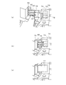
図1(a)は本実施形態の筒内圧検出ユニット付き燃料噴射装置の側面図であり、図1(b)は、図1(a)に示す燃料噴射装置に合成樹脂モールドが被覆された状態を説明するための図であり、図1(c)は図1(b)において矢印Bの方向からみた本体コネクタ部70を説明するための図である。図1(a)は、説明のために合成樹脂モールドが無い状態を示している(ただし、増幅回路ユニット81は、合成樹脂モールド81aによって封止成形されたものが示されている)。また、図2(a)~(d)は、それぞれ燃料噴射装置1、筒内圧検出ユニット201を装着する途中の状態、筒内圧検出ユニット201が装着された状態、及び筒内圧検出ユニット201が装着された後に合成樹脂モールド202で被覆した最終形態、すなわち筒内圧検出ユニット付き燃料噴射装置200を示す。図2(b)に示すように、筒内圧検出ユニット201を矢印Cで示す方向に移動させることによって、燃料噴射装置1に装着する。
図1(a)は本実施形態の筒内圧検出ユニット付き燃料噴射装置の側面図であり、図1(b)は、図1(a)に示す燃料噴射装置に合成樹脂モールドが被覆された状態を説明するための図であり、図1(c)は図1(b)において矢印Bの方向からみた本体コネクタ部70を説明するための図である。図1(a)は、説明のために合成樹脂モールドが無い状態を示している(ただし、増幅回路ユニット81は、合成樹脂モールド81aによって封止成形されたものが示されている)。また、図2(a)~(d)は、それぞれ燃料噴射装置1、筒内圧検出ユニット201を装着する途中の状態、筒内圧検出ユニット201が装着された状態、及び筒内圧検出ユニット201が装着された後に合成樹脂モールド202で被覆した最終形態、すなわち筒内圧検出ユニット付き燃料噴射装置200を示す。図2(b)に示すように、筒内圧検出ユニット201を矢印Cで示す方向に移動させることによって、燃料噴射装置1に装着する。
燃料噴射装置1は、内燃機関の燃焼室内に燃料を噴射する装置であり、内部に周知の構成要素である弁体、弁体を駆動するソレノイド(駆動回路)、弁体を付勢するスプリングなどを有し、先端部の噴射口5から燃料を噴射する。燃料噴射装置1は、ソレノイドが内蔵される金属製の大径部ケーシング3と、先端部に噴射口5が設けられた金属製の小径部ケーシング4とを有する。
筒内圧検出ユニット201は、圧力検出素子2と、圧力検出素子2が先端部に固定された円筒状のセンサ固定部材13と、増幅回路ユニット81と、圧力検出素子2と増幅回路ユニット81を接続する接続部材12とを予め組み上げることによって構成され、センサ固定部材13を、燃料噴射装置1の小径部ケーシング4の先端側(噴射口5側)に嵌め込むことによって、筒内圧検出ユニット201が燃料噴射装置1に装着される。したがって、圧力検出素子2は、燃料噴射装置1の先端部(噴射口5を囲む位置)に装着され、接続部材12によって増幅回路ユニット81に接続されている。増幅回路ユニット81は、耐熱性の合成樹脂モールド81aによって被覆(封止成形)されている。増幅回路ユニット81には、サブコネクタピン91~93が固定されており、合成樹脂モールド81aによってサブコネクタピン91~93を含むサブコネクタ部82が形成される。
燃料噴射装置1には、合成樹脂モールド203の一部によって構成され、電子制御ユニット(以下「ECU」という)60(図8~9参照)からの接続線が接続される本体コネクタ部70が固定されている。ECU60は、燃料噴射装置1の駆動制御を行うとともに、筒内圧検出ユニット201による筒内圧の検出を行う。
本体コネクタ部70は、ECU60から燃料噴射装置1の駆動信号が供給される駆動信号線が接続される第1コネクタピン21~23と、圧力検出信号をECU60に供給するための検出信号線等(電源接続線、アース接続線)が接続される第2コネクタピン71~73と、第2コネクタピン71~73をサブコネクタピン91~93と接続するための端子収容凹部74と、筒内圧検出ユニット201を装着するときにサブコネクタ部82を保持するための保持部材75とを備えている。端子収容凹部74には、第2コネクタピン71~73が露出しており、第2コネクタピン71~73がサブコネクタピン91~93と接続可能に構成されている。
サブコネクタ部82と本体コネクタ部70との結合部には、固化する前の接着剤の漏れを防止するための補助部材76が介装される。
サブコネクタ部82と本体コネクタ部70との結合部には、固化する前の接着剤の漏れを防止するための補助部材76が介装される。
本体コネクタ部70の第1コネクタピン21~23及び第2コネクタピン71~73と嵌合可能なコネクタ部材(図示せず)が、ECU60からの接続線の先端部に固定され、そのコネクタ部材が嵌合することによって、接続線と各コネクタピン21~23,71~73とが接続される。
図2(c)及び(d)に示すように、筒内圧検出ユニット201と燃料噴射装置1とが一体化された後に、合成樹脂モールド81aが被覆された増幅回路ユニット81、接続部材12、及びセンサ固定部材13の一部(増幅回路ユニット81に近い側)が合成樹脂モールド202によって被覆される。なお、筒内圧検出ユニット201と燃料噴射装置1とが一体化された後であって、合成樹脂モールド202による被覆を行う前に、サブコネクタピン91~93がそれぞれ第2コネクタピン71~73と抵抗溶接され、端子収容凹部74へ防水用の接着剤(例えばシリコン接着剤)の充填が行われる。
図1(b)において右下がりのハッチングを付して示す部分が、図2(a)に示される燃料噴射装置1の本体コネクタ部70を構成する合成樹脂モールド203に相当し、右上がりのハッチングを付して示す部分が、図2(d)に示す最後に被覆される合成樹脂モールド202に相当する。
図3は、サブコネクタピン91~93と、第2コネクタピン71~73との接続をより詳細に説明するための斜視図であり、同図(a)はサブコネクタ部82と、本体コネクタ部70とを結合する前の状態を示し、同図(b)は結合が完了した状態を示し、同図(c)はコネクタピンの抵抗溶接完了後に、接着剤77を充填した状態を示す。
サブコネクタ部82と本体コネクタ部70との間には補助部材76が介装され、サブコネクタ部82は図の右方向に押し込むことによって、本体コネクタ部70の2つの保持部材75に挟み込まれて固定される(同図(b))。図3(b)に示す結合が完了した状態では、端子収容凹部74、サブコネクタ部82、及び補助部材76によって、固化する前の接着剤を貯留可能な貯留部が形成され、補助部材76を介装させることによって、結合部から固化する前の接着剤が漏れることが防止される。
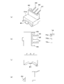
図4は、増幅回路ユニット81を被覆し、サブコネクタ部82を形成する合成樹脂モールド81aの構造を詳細に説明するための図であり、同図(a)~(d)はそれぞれ合成樹脂モールド81a(サブコネクタピン91~93を含む)の斜視図、平面図、正面図、及び側面図であり、平面図(b)には補助部材76の平面図も示されている。
合成樹脂モールド81aは、サブコネクタピン91~93を保持するサブコネクタ部82を形成し、燃料噴射装置1の大径部ケーシング3の外周面に密着可能に湾曲した底面83と、固定用突起部84とを有する。固定用突起部84は、大径部ケーシング3に設けられた固定用凹部(図示せず)に嵌入され、合成樹脂モールド81aが大径部ケーシング3上に固定される。サブコネクタ部82にはテーパ部85が形成されており、このテーパ部85によって、サブコネクタ部82を本体コネクタ部70に結合する際に、2つの保持部材75の間にサブコネクタ部82を円滑に嵌め込むことが可能となる。
補助部材76は、サブコネクタピン91~93に対応する切り欠き部76a,76b,及び76cを有し、サブコネクタ部82を本体コネクタ部70に結合したときに、サブコネクタピン91~93が切り欠き部76a,76b,76cを通るように構成されている。
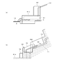
図5(a)は、接続部材12の装着状態を説明するための図であり、増幅回路ユニット81に接続された接続部材12は、可能な限り大径部ケーシング3に接するように装着される。これによって、最終的に合成樹脂モールド202を被覆する際に、接続部材12がはがれる(浮き上がる)ことが防止される。
図5(b)は、サブコネクタピン91~93と、第2コネクタピン71~73との接続を説明するための図であり、サブコネクタ部82を本体コネクタ部70と結合させると、サブコネクタピン91(92,93)は、第2コネクタピン71(72,73)と端子収容凹部74内で接触する。そして、この接触部(破線の楕円PWで示す)を抵抗溶接することによって、両者が接続される。補助部材76は、サブコネクタ部82と本体コネクタ部70との間に介装され、この図に示す位置に固定される。
図6は、接続部材12の構造を説明するための図であり、図6(a)は平面図、図6(b)は、図6(a)のA-A線断面図である。接続部材12は、銅線17を接着剤16(エポキシ系樹脂)を介してポリイミド製の被覆部材14,15によって被覆して構成される、フレキシブル配線基板として知られる構造を有し、断線することなく容易に折り曲げ可能なものである。接続部材12は、圧力検出素子2に接続される先端部近傍(図6(a)にRINで示す部分)は、図7に示すように金属製のセンサ固定部材13の内側を通り、先端部近傍部分RINと、増幅回路ユニット81との間は、燃料噴射装置1の大径部ケーシング3の外周面に沿うように配置されている。
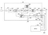
図8は増幅回路ユニット81の構成を示すブロック図であり、増幅回路ユニット81は、コンデンサ41、ローパスフィルタ42、チャージアンプ43、ハイパスフィルタ44、増幅回路45、感度調整回路46、故障検出用回路47、基準電圧回路48、電源ノイズフィルタ49、交流接地コンデンサ50、及びサブコネクタ部82を構成するサブコネクタピン91~93を備えている。サブコネクタピン91は本体コネクタ部70(コネクタピン71)及びアース接続線61を介してECU60のアースに接続され、サブコネクタピン92には、本体コネクタ部70(コネクタピン72)及び電源接続線62を介して直流電源電圧(例えば5V)が供給され、サブコネクタピン93は、本体コネクタ部70(コネクタピン73)及び信号接続線(検出信号線)63を介して、ECU60のAD変換器に接続される。サブコネクタピン92に接続された電源線53は、電源ノイズフィルタ49を介して、基準電圧回路48に接続されている。
コンデンサ41により、圧力検出素子2から接続部材12を介して、入力される検出信号の直流成分がカットされ、入力検出信号の交流成分のみがローパスフィルタ42に入力される。ローパスフィルタ42は、不要な高周波成分を減衰させる。チャージアンプ43は、入力信号を積分しつつ増幅することによって、圧力変化率を示す入力信号を圧力値を示す圧力信号に変換する。ハイパスフィルタ44は、不要な低周波成分を減衰させる。増幅回路45は、ハイパスフィルタ44の出力信号を増幅する。
感度調整回路46は、たとえば複数の抵抗素子の組み合わせで構成され、圧力検出素子2を接続して、テスト用の圧力を圧力検出素子2に印加したときの、増幅回路45の出力信号レベルが所定レベルとなるように、増幅回路45のゲインを調整するための回路である。具体的には、予め装着されている複数の抵抗素子を接続する配線をカットすることによって、全体としての抵抗値を調整し、ゲイン調整が行われる。なお、このゲイン調整は増幅回路ユニット81を合成樹脂モールド81aで被覆する前に行われる。
基準電圧回路48は、ECU60から供給される電源電圧VS1から基準電圧VREFを生成して、チャージアンプ43、ハイパスフィルタ44、及び増幅回路45に供給する。基準電圧VREFは、直流電圧をオフセットさせる(0Vを1Vに上げる)ための電圧である。電源ノイズフィルタ49は電源接続線62を介して混入するノイズを除去するローパスフィルタである。
増幅回路ユニット81のアース線52は、サブコネクタ部82、本体接続部70、及びアース接続線61を介してECU60のアースと接続されているが、燃料噴射装置1の筐体とは交流接地コンデンサ50を介して接続されているのみであり、直流的には燃料噴射装置1の筐体と接続されていない。これによって、以下に説明するようにアース接続線61の断線を、ECU60で検出することが可能となる。なお、燃料噴射装置1の筐体は内燃機関のシリンダヘッドと導通している。
故障検出用回路47は、図9に示すように電源線LSにプルアップ抵抗RPUを接続することによって構成される。ECU60にはアースに接続されたプルダウン抵抗RPDが設けられており、入力直流電圧VINに応じて電源接続線62または信号接続線63の断線もしくは地絡(アースとの短絡)、またはアース接続線61の断線が検出可能に構成されている。すなわち、接続線62または63の断線もしくは地絡が発生すると、入力直流電圧VINは「0」となり、またアース接続線61の断線が発生すると、入力直流電圧VINは、正常電圧VNLより高くなる。したがって、入力直流電圧VINが正常電圧VNLより所定電圧以上と高くなったときは、アース接続線61の断線が発生していると判定できる。
図10は、燃料噴射装置1の駆動用ソレノイド24と、ECU60との接続を説明するための図であり、ソレノイド24の両端は本体コネクタ部70の第1コネクタピン22,23を介してECU60と接続され、第1コネクタピン21は燃料噴射装置1において筐体に接地されている。
以上のように本実施形態では、圧力検出素子2、増幅回路ユニット81、及びそれらを接続する接続部材12を含む筒内圧検出ユニット201を燃料噴射装置1と一体化することによって、筒内圧検出ユニット付き燃料噴射装置200が構成され、その筒内圧検出ユニット付き燃料噴射装置200が内燃機関に装着される。したがって、燃料噴射装置1の駆動信号の影響を低減するとともに、圧力検出素子2及び増幅回路ユニット81を燃料噴射装置1と一体化し、内燃機関に実装するときの作業性を高めることができる。また、サブコネクタ部82を本体コネクタ部70に嵌め込むことによって、筒内圧検出ユニット201の増幅回路ユニット81が燃料噴射装置1に固定され、かつサブコネクタピン91~93と第2コネクタピン71~73とが接触するので、サブコネクタピン91~93と第2コネクタピン71~73を接続する作業を容易に行うことができる。
また圧力検出素子2が固定された円筒状のセンサ固定部材13、増幅回路ユニット81、及び圧力検出素子2と増幅回路ユニット81を接続する接続部材12を予め組み上げて筒内圧検出ユニット201が構成され、その筒内圧検出ユニット201が、センサ固定部材13を燃料噴射装置1の先端部(小径部ケーシング4の先端側)に嵌め込むことによって、筒内圧検出ユニット付き燃料噴射装置200が構成されるので、筒内圧検出ユニット201を燃料噴射装置1と一体化する際の作業性を高めることができる。
また本体コネクタ部70の端子収容凹部74内でサブコネクタピン91~93が第2コネクタピン71~73と接続され、その端子収容凹部74に接着剤77が充填されるので、サブコネクタピン91~93と第2コネクタピン71~73の接続部に水が侵入することを確実に防止することができる。
またサブコネクタ部82と本体コネクタ部70の結合部には、接着剤77の漏れを防止するための補助部材76が介装されるので、固化する前の接着剤が結合部の間隙から漏れることを防止できる。
また筒内圧検出ユニット201の主要部、すなわち合成樹脂モールド81aが被覆された増幅回路ユニット81、接続部材12、及びセンサ固定部材13の一部(増幅回路ユニット81に近い部分)が合成樹脂モールド202によって被覆されるので、燃料噴射装置1と一体化した状態での取り扱いが容易となり、かつ増幅回路ユニット81の防水、断熱、及び絶縁の効果を確実に得ることができる。
また増幅回路ユニット81は、耐熱性の合成樹脂モールド81aによって被覆される(封止成形される)ので、耐熱性を高めて、最終的に合成樹脂モールド202を被覆する際に比較的高温に一定時間さらされても、故障することを確実に回避できる。
また本体コネクタ部70は、第2コネクタピン71~73とともに駆動信号線が接続される第1コネクタピン21~23を備えるので、ECU60からの接続線を燃料噴射装置1に接続する際の作業性を高めることができる。
[変形例]
上述した実施形態では、本体コネクタ部70は、第1コネクタピン21~23と、第2コネクタピン71~73とを備えるようにしたが、本体コネクタ部70を第1本体コネクタ部と、第2本体コネクタ部に分割し、第1本体コネクタ部は燃料噴射装置1のコネクタピン21~23を有し、第2本体コネクタ部は増幅回路ユニット81のサブコネクタピン91~93に接続される第2コネクタピン71~73を有する構成としてもよい。
上述した実施形態では、本体コネクタ部70は、第1コネクタピン21~23と、第2コネクタピン71~73とを備えるようにしたが、本体コネクタ部70を第1本体コネクタ部と、第2本体コネクタ部に分割し、第1本体コネクタ部は燃料噴射装置1のコネクタピン21~23を有し、第2本体コネクタ部は増幅回路ユニット81のサブコネクタピン91~93に接続される第2コネクタピン71~73を有する構成としてもよい。
このように本体コネクタ部70を第1及び第2本体コネクタ部に分割することによって、圧力検出信号が伝送される接続線63が、比較的大きな電流が流れる駆動信号線から離間し、燃料噴射装置1の駆動信号が圧力検出信号に与える影響を軽減することができる。
また合成樹脂モールド202,203は、セラミックモールドに代えてもよい。また増幅回路ユニット81の感度調整回路46を複数の抵抗素子の組み合わせで構成するようにしたが、これに限るものではなく、例えば不揮発メモリにゲイン調整データ書き込むことによってゲイン調整を行うようにしてもよい。
また増幅回路ユニット81は、ガラスエポキシ樹脂基板上に構成し、接続部材12をそのガラスエポキシ樹脂基板に接続するようにしてもよい。
また増幅回路ユニット81は、ガラスエポキシ樹脂基板上に構成し、接続部材12をそのガラスエポキシ樹脂基板に接続するようにしてもよい。
1 燃料噴射装置
2 圧力検出素子
21~23 第1コネクタピン
60 電子制御ユニット
70 本体コネクタ部
71~73 第2コネクタピン
74 端子収容凹部
76 補助部材
77 接着剤
81 増幅回路ユニット
81a 合成樹脂モールド
82 サブコネクタ部
91~93 サブコネクタピン
200 筒内圧検出ユニット付き燃料噴射装置
201 筒内圧検出ユニット
202 合成樹脂モールド
2 圧力検出素子
21~23 第1コネクタピン
60 電子制御ユニット
70 本体コネクタ部
71~73 第2コネクタピン
74 端子収容凹部
76 補助部材
77 接着剤
81 増幅回路ユニット
81a 合成樹脂モールド
82 サブコネクタ部
91~93 サブコネクタピン
200 筒内圧検出ユニット付き燃料噴射装置
201 筒内圧検出ユニット
202 合成樹脂モールド
Claims (7)
- 内燃機関の燃焼室内に燃料を噴射する燃料噴射装置の先端部に装着される圧力検出素子と、該圧力検出素子から出力される信号を増幅して圧力検出信号を出力する増幅回路を含む増幅回路ユニットとを備え、前記燃焼室内の圧力を検出する筒内圧検出装置において、
前記圧力検出素子、前記増幅回路ユニット、及び前記圧力検出素子と前記増幅回路ユニットとを接続する接続部材を含む筒内圧検出ユニットを前記燃料噴射装置と一体化することによって、筒内圧検出ユニット付き燃料噴射装置を構成し、前記筒内圧検出ユニット付き燃料噴射装置を前記内燃機関に装着して前記圧力を検出し、
前記燃料噴射装置は、該燃料噴射装置を制御する制御ユニットへ前記圧力検出信号を供給するための検出信号線が接続される検出信号線接続端子を有する本体コネクタ部を備え、
前記筒内圧検出ユニットは、前記増幅回路ユニットと一体に構成され、前記本体コネクタ部に嵌め込むことによって結合可能なサブコネクタ部を備え、
前記サブコネクタ部は、前記圧力検出信号を前記本体コネクタ部に伝達するためのサブ接続端子を有し、前記サブコネクタ部を前記本体コネクタ部に結合することによって、前記サブ接続端子が前記検出信号線接続端子と接触するように構成されることを特徴とする筒内圧検出装置。 - 前記本体コネクタ部は、前記検出信号線接続端子が露出し、前記サブコネクタ部のサブ接続端子を収容する端子収容凹部を有し、該端子収容凹部内で前記サブ接続端子が前記検出信号線接続端子と接続され、前記端子収容凹部内に接着剤が充填される請求項1に記載の筒内圧検出装置。
- 前記サブコネクタ部と前記本体コネクタ部の結合部には、前記接着剤の漏れを防止するための補助部材が介装される請求項2に記載の筒内圧検出装置。
- 前記圧力検出素子と前記増幅回路ユニットとを接続する接続部材、前記増幅回路ユニット、及び前記端子収容凹部は、前記筒内圧検出ユニットが前記燃料噴射装置と一体化された後にモールド材によって被覆される請求項2または3に記載の筒内圧検出装置。
- 前記増幅回路ユニットは、耐熱性樹脂によって封止成形されている請求項4に記載の筒内圧検出装置。
- 前記筒内圧検出ユニットは、前記圧力検出素子が先端部に固定された円筒状のセンサ固定部材と、前記増幅回路ユニットと、前記圧力検出素子と前記増幅回路ユニットとを接続する接続部材とを予め組み上げることによって構成され、前記センサ固定部材が前記燃料噴射装置の先端部に嵌め込まれる請求項1から5の何れか1項に記載の筒内圧検出装置。
- 前記本体コネクタ部は、前記制御ユニットから前記燃料噴射装置の駆動信号を供給する駆動信号線が接続される駆動信号線接続端子を有する請求項1から6の何れか1項に記載の筒内圧検出装置。
Priority Applications (1)
| Application Number | Priority Date | Filing Date | Title |
|---|---|---|---|
| JP2016573297A JP6285053B2 (ja) | 2015-02-03 | 2016-01-27 | 筒内圧検出装置 |
Applications Claiming Priority (2)
| Application Number | Priority Date | Filing Date | Title |
|---|---|---|---|
| JP2015019061 | 2015-02-03 | ||
| JP2015-019061 | 2015-08-28 |
Publications (1)
| Publication Number | Publication Date |
|---|---|
| WO2016125637A1 true WO2016125637A1 (ja) | 2016-08-11 |
Family
ID=56563987
Family Applications (1)
| Application Number | Title | Priority Date | Filing Date |
|---|---|---|---|
| PCT/JP2016/052222 Ceased WO2016125637A1 (ja) | 2015-02-03 | 2016-01-27 | 筒内圧検出装置 |
Country Status (2)
| Country | Link |
|---|---|
| JP (1) | JP6285053B2 (ja) |
| WO (1) | WO2016125637A1 (ja) |
Citations (3)
| Publication number | Priority date | Publication date | Assignee | Title |
|---|---|---|---|---|
| JP2009536995A (ja) * | 2006-05-12 | 2009-10-22 | デルファイ・テクノロジーズ・インコーポレーテッド | 燃料噴射器 |
| JP2014119260A (ja) * | 2012-12-13 | 2014-06-30 | Keihin Corp | 筒内圧センサ付き燃料噴射弁 |
| JP2015215329A (ja) * | 2014-04-21 | 2015-12-03 | 本田技研工業株式会社 | 筒内圧検出装置 |
-
2016
- 2016-01-27 JP JP2016573297A patent/JP6285053B2/ja not_active Expired - Fee Related
- 2016-01-27 WO PCT/JP2016/052222 patent/WO2016125637A1/ja not_active Ceased
Patent Citations (3)
| Publication number | Priority date | Publication date | Assignee | Title |
|---|---|---|---|---|
| JP2009536995A (ja) * | 2006-05-12 | 2009-10-22 | デルファイ・テクノロジーズ・インコーポレーテッド | 燃料噴射器 |
| JP2014119260A (ja) * | 2012-12-13 | 2014-06-30 | Keihin Corp | 筒内圧センサ付き燃料噴射弁 |
| JP2015215329A (ja) * | 2014-04-21 | 2015-12-03 | 本田技研工業株式会社 | 筒内圧検出装置 |
Also Published As
| Publication number | Publication date |
|---|---|
| JP6285053B2 (ja) | 2018-02-28 |
| JPWO2016125637A1 (ja) | 2017-08-24 |
Similar Documents
| Publication | Publication Date | Title |
|---|---|---|
| CN105164401B (zh) | 缸内压力检测装置 | |
| CN104350271B (zh) | 燃料喷射装置 | |
| CN101614603B (zh) | 用于探测内燃机的进气管中的压力和温度的装置 | |
| US9513306B2 (en) | Sensor unit for a vehicle | |
| JP4903165B2 (ja) | 電気絶縁皮膜によって保持された圧電式力センサ用部品又は圧電式圧力センサ用部品 | |
| JP6318605B2 (ja) | 溶接部を有する継手構造の組付構造 | |
| US20030233886A1 (en) | Flow rate sensor | |
| US20180142655A1 (en) | Fuel injector including sensor | |
| US20110287636A1 (en) | Multifunction plug connector of an oil pan of a vehicle | |
| KR20060060539A (ko) | 유량 측정 장치 | |
| CN110890205A (zh) | 用于具有一个感应接口的现场设备的具有一个次级线圈的组合件 | |
| JP5956532B2 (ja) | 筒内圧検出装置 | |
| JP4867559B2 (ja) | 圧力センサおよび圧力センサの取付構造 | |
| JP2010256213A (ja) | 圧力センサ | |
| JP6503190B2 (ja) | 筒内圧センサ付き燃料噴射弁 | |
| KR100536377B1 (ko) | 유량 센서 | |
| KR101374381B1 (ko) | 차량용 전류센서 및 그 제조방법 | |
| JP6285053B2 (ja) | 筒内圧検出装置 | |
| JP5672138B2 (ja) | 燃料噴射装置 | |
| US10539434B2 (en) | Air flow rate measurement device | |
| US10012194B2 (en) | Fuel injection valve with cylinder internal pressure sensor | |
| US10996127B2 (en) | Pressure detection device and pressure detection system having first and second housings electrically insulated from each other | |
| JP6027423B2 (ja) | 筒内圧センサ付き燃料噴射弁 | |
| KR20130131980A (ko) | 차량용 맵센서의 터미널과 피씨비 결합구조 | |
| US20160208755A1 (en) | Fuel injection valve with cylinder internal pressure sensor |
Legal Events
| Date | Code | Title | Description |
|---|---|---|---|
| 121 | Ep: the epo has been informed by wipo that ep was designated in this application |
Ref document number: 16746468 Country of ref document: EP Kind code of ref document: A1 |
|
| ENP | Entry into the national phase |
Ref document number: 2016573297 Country of ref document: JP Kind code of ref document: A |
|
| NENP | Non-entry into the national phase |
Ref country code: DE |
|
| 122 | Ep: pct application non-entry in european phase |
Ref document number: 16746468 Country of ref document: EP Kind code of ref document: A1 |