WO2016125375A1 - 処置具 - Google Patents
処置具 Download PDFInfo
- Publication number
- WO2016125375A1 WO2016125375A1 PCT/JP2015/083641 JP2015083641W WO2016125375A1 WO 2016125375 A1 WO2016125375 A1 WO 2016125375A1 JP 2015083641 W JP2015083641 W JP 2015083641W WO 2016125375 A1 WO2016125375 A1 WO 2016125375A1
- Authority
- WO
- WIPO (PCT)
- Prior art keywords
- tension
- unit
- holding
- tissue
- treatment tool
- Prior art date
Links
Images


Classifications
-
- A—HUMAN NECESSITIES
- A61—MEDICAL OR VETERINARY SCIENCE; HYGIENE
- A61B—DIAGNOSIS; SURGERY; IDENTIFICATION
- A61B17/00—Surgical instruments, devices or methods, e.g. tourniquets
- A61B17/28—Surgical forceps
- A61B17/2812—Surgical forceps with a single pivotal connection
-
- A—HUMAN NECESSITIES
- A61—MEDICAL OR VETERINARY SCIENCE; HYGIENE
- A61B—DIAGNOSIS; SURGERY; IDENTIFICATION
- A61B17/00—Surgical instruments, devices or methods, e.g. tourniquets
- A61B17/02—Surgical instruments, devices or methods, e.g. tourniquets for holding wounds open; Tractors
- A61B17/0218—Surgical instruments, devices or methods, e.g. tourniquets for holding wounds open; Tractors for minimally invasive surgery
-
- A—HUMAN NECESSITIES
- A61—MEDICAL OR VETERINARY SCIENCE; HYGIENE
- A61B—DIAGNOSIS; SURGERY; IDENTIFICATION
- A61B17/00—Surgical instruments, devices or methods, e.g. tourniquets
- A61B17/08—Wound clamps or clips, i.e. not or only partly penetrating the tissue ; Devices for bringing together the edges of a wound
- A61B17/083—Clips, e.g. resilient
-
- A—HUMAN NECESSITIES
- A61—MEDICAL OR VETERINARY SCIENCE; HYGIENE
- A61B—DIAGNOSIS; SURGERY; IDENTIFICATION
- A61B17/00—Surgical instruments, devices or methods, e.g. tourniquets
- A61B17/10—Surgical instruments, devices or methods, e.g. tourniquets for applying or removing wound clamps, e.g. containing only one clamp or staple; Wound clamp magazines
-
- A—HUMAN NECESSITIES
- A61—MEDICAL OR VETERINARY SCIENCE; HYGIENE
- A61B—DIAGNOSIS; SURGERY; IDENTIFICATION
- A61B34/00—Computer-aided surgery; Manipulators or robots specially adapted for use in surgery
- A61B34/70—Manipulators specially adapted for use in surgery
- A61B34/71—Manipulators operated by drive cable mechanisms
-
- A—HUMAN NECESSITIES
- A61—MEDICAL OR VETERINARY SCIENCE; HYGIENE
- A61B—DIAGNOSIS; SURGERY; IDENTIFICATION
- A61B90/00—Instruments, implements or accessories specially adapted for surgery or diagnosis and not covered by any of the groups A61B1/00 - A61B50/00, e.g. for luxation treatment or for protecting wound edges
- A61B90/06—Measuring instruments not otherwise provided for
-
- A—HUMAN NECESSITIES
- A61—MEDICAL OR VETERINARY SCIENCE; HYGIENE
- A61B—DIAGNOSIS; SURGERY; IDENTIFICATION
- A61B17/00—Surgical instruments, devices or methods, e.g. tourniquets
- A61B17/12—Surgical instruments, devices or methods, e.g. tourniquets for ligaturing or otherwise compressing tubular parts of the body, e.g. blood vessels, umbilical cord
- A61B17/122—Clamps or clips, e.g. for the umbilical cord
- A61B17/1227—Spring clips
-
- A—HUMAN NECESSITIES
- A61—MEDICAL OR VETERINARY SCIENCE; HYGIENE
- A61B—DIAGNOSIS; SURGERY; IDENTIFICATION
- A61B17/00—Surgical instruments, devices or methods, e.g. tourniquets
- A61B17/12—Surgical instruments, devices or methods, e.g. tourniquets for ligaturing or otherwise compressing tubular parts of the body, e.g. blood vessels, umbilical cord
- A61B17/128—Surgical instruments, devices or methods, e.g. tourniquets for ligaturing or otherwise compressing tubular parts of the body, e.g. blood vessels, umbilical cord for applying or removing clamps or clips
- A61B17/1285—Surgical instruments, devices or methods, e.g. tourniquets for ligaturing or otherwise compressing tubular parts of the body, e.g. blood vessels, umbilical cord for applying or removing clamps or clips for minimally invasive surgery
-
- A—HUMAN NECESSITIES
- A61—MEDICAL OR VETERINARY SCIENCE; HYGIENE
- A61B—DIAGNOSIS; SURGERY; IDENTIFICATION
- A61B17/00—Surgical instruments, devices or methods, e.g. tourniquets
- A61B2017/00017—Electrical control of surgical instruments
-
- A—HUMAN NECESSITIES
- A61—MEDICAL OR VETERINARY SCIENCE; HYGIENE
- A61B—DIAGNOSIS; SURGERY; IDENTIFICATION
- A61B17/00—Surgical instruments, devices or methods, e.g. tourniquets
- A61B2017/0046—Surgical instruments, devices or methods, e.g. tourniquets with a releasable handle; with handle and operating part separable
- A61B2017/00473—Distal part, e.g. tip or head
-
- A—HUMAN NECESSITIES
- A61—MEDICAL OR VETERINARY SCIENCE; HYGIENE
- A61B—DIAGNOSIS; SURGERY; IDENTIFICATION
- A61B17/00—Surgical instruments, devices or methods, e.g. tourniquets
- A61B2017/00982—General structural features
- A61B2017/00991—Telescopic means
-
- A—HUMAN NECESSITIES
- A61—MEDICAL OR VETERINARY SCIENCE; HYGIENE
- A61B—DIAGNOSIS; SURGERY; IDENTIFICATION
- A61B17/00—Surgical instruments, devices or methods, e.g. tourniquets
- A61B17/02—Surgical instruments, devices or methods, e.g. tourniquets for holding wounds open; Tractors
- A61B2017/0287—Surgical instruments, devices or methods, e.g. tourniquets for holding wounds open; Tractors with elastic retracting members connectable to a frame, e.g. hooked elastic wires
-
- A—HUMAN NECESSITIES
- A61—MEDICAL OR VETERINARY SCIENCE; HYGIENE
- A61B—DIAGNOSIS; SURGERY; IDENTIFICATION
- A61B17/00—Surgical instruments, devices or methods, e.g. tourniquets
- A61B17/28—Surgical forceps
- A61B17/29—Forceps for use in minimally invasive surgery
- A61B2017/2901—Details of shaft
- A61B2017/2905—Details of shaft flexible
-
- A—HUMAN NECESSITIES
- A61—MEDICAL OR VETERINARY SCIENCE; HYGIENE
- A61B—DIAGNOSIS; SURGERY; IDENTIFICATION
- A61B34/00—Computer-aided surgery; Manipulators or robots specially adapted for use in surgery
- A61B34/70—Manipulators specially adapted for use in surgery
- A61B34/71—Manipulators operated by drive cable mechanisms
- A61B2034/715—Cable tensioning mechanisms for removing slack
-
- A—HUMAN NECESSITIES
- A61—MEDICAL OR VETERINARY SCIENCE; HYGIENE
- A61B—DIAGNOSIS; SURGERY; IDENTIFICATION
- A61B90/00—Instruments, implements or accessories specially adapted for surgery or diagnosis and not covered by any of the groups A61B1/00 - A61B50/00, e.g. for luxation treatment or for protecting wound edges
- A61B90/06—Measuring instruments not otherwise provided for
- A61B2090/064—Measuring instruments not otherwise provided for for measuring force, pressure or mechanical tension
Definitions
- the present invention relates to a treatment instrument that can be inserted into a patient in a surgical operation or the like and can be observed and treated.
- Medical devices for observing an organ in a body cavity or performing treatment by inserting a treatment tool into a patient's body cavity and pulling the distal end of the treatment tool with a wire or the like are widely used.
- a plurality of treatment tools such as an endoscope for observation, forceps for grasping tissue, or an electric scalpel for excising tissue are often inserted into a body cavity.
- the plurality of treatment tools may interfere with each other in a narrow body cavity.
- Patent Documents 1 to 3 disclose techniques in which the distal joint of the treatment instrument has flexibility and can be bent. In this way, it is possible to avoid a certain amount of interference by curving the distal end of the treatment instrument.
- the tension applied to the connecting portion connecting the treatment instrument and the main body may change, which may affect the tissue.
- the present invention has been made paying attention to the above-mentioned problem, and can adjust the tension of the connecting portion that connects the holding portion that holds the tissue and the main body portion, adjusts the tissue to an accurate state,
- An object of the present invention is to provide a treatment instrument that can treat and avoid interference between treatment instruments.
- the treatment tool is: A main body having a case and a hollow shaft provided in the case; A holding unit for holding biological tissue in a body cavity; A connecting portion that is inserted into the shaft and connects the main body portion and the holding portion; A tension adjusting unit capable of adjusting the tension of the connecting part by moving the connecting part with respect to the shaft; It is characterized by providing.
- the tension adjusting unit holds the tension of the connection unit in the tension holding mode.
- the tension adjusting unit is A drive unit provided in the case; A tension detection unit for detecting the tension of the connection unit; A control unit that controls the drive unit based on a detection value detected by the tension detection unit; Have
- the controller is When it is determined that the detection value detected by the tension detection unit has changed abruptly per unit time, the drive unit is stopped.
- the controller is The tension detection unit detects a first detection value that rapidly decreases per unit time, Moving the connecting part to the shaft side for a certain time by the driving part; The second detection value detected by the tension detection unit after the movement is compared with the first detection value, and when the increase amount is equal to or less than a predetermined amount, the drive unit is stopped.
- the connecting portion has a wire.
- connection part has an elastic member.
- the elastic member has anisotropy.
- the holding part has a grip part for sandwiching the living tissue.
- the treatment tool according to one embodiment of the present invention is:
- the holding part has a hook for hooking the living tissue.
- the treatment tool it is possible to adjust the tension of the connection portion that connects the holding portion that holds the tissue and the main body portion, and it is possible to adjust the tissue to an appropriate state and perform an appropriate treatment. At the same time, it is possible to avoid interference between the treatment instruments.
- the treatment tool of a 1st embodiment is shown.
- the treatment tool of a 1st embodiment shows the state where a tissue is grasped.
- tissue is shown.
- the treatment tool of a 1st embodiment shows the state where the tissue is exfoliated.
- maintenance part of the treatment tool of 1st Embodiment is shown.
- the treatment tool 1 of the other example of 1st Embodiment is shown.
- the state of tension of treatment tool 1 of other examples of a 1st embodiment is shown.
- the treatment tool of 2nd Embodiment is shown.
- the treatment tool of a 2nd embodiment shows the state which has drawn out the elastic member.
- tissue is shown.
- the treatment tool of a 2nd embodiment shows the state where the tissue is exfoliated.
- the other usage method of the treatment tool of 2nd Embodiment is shown.
- the other usage method of the treatment tool of 2nd Embodiment is shown.
- the treatment tool of 3rd Embodiment is shown.
- the figure which looked at the treatment tool of a 3rd embodiment from the upper part is shown.
- the treatment tool of 4th Embodiment is shown. It is the schematic which shows an example of the treatment using the treatment tool of this embodiment.
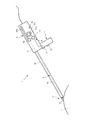
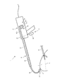
- FIG. 1 shows a treatment instrument 1 according to the first embodiment.
- the treatment instrument 1 includes a case 21 and a main body 2 having a hollow shaft 22 provided in the case 21, a holding portion 3 that holds a living tissue T in a body cavity, and a main body that is inserted into the shaft 22.
- the treatment instrument 1 of the first embodiment further includes an operation unit 5 that converts to a tension holding mode that holds the tension of the connection unit 4, and the tension adjustment unit 6 adjusts the tension of the connection unit 4 in the tension holding mode. To do.
- the main body 2 includes a case 21 that houses the tension adjusting unit 6 and the like, and a hollow shaft 22 that is provided in the case 21 and passes through the connecting portion 4.
- the holding unit 3 is connected to one end of the connection unit 4.
- the holding unit 3 according to the first embodiment includes a holding unit 31 that holds a living tissue in a body cavity.
- the grasping forceps 31 has a structure that can be opened and closed by operating a grasping opening / closing operation member 52 described later.
- connection part 4 of 1st Embodiment is the wire 41 which goes in / out with respect to the shaft 22 when the moving member 61b moves.
- the operation unit 5 includes a tension holding mode operation member 51 that converts to a tension holding mode for holding the tension of the connection unit 4.
- the operation unit 5 according to the first embodiment includes a grip opening / closing operation member 52 that operates opening / closing of the grip unit 31.
- the tension holding mode operation member 51 and the grip opening / closing operation member 52 are preferably configured by toggle buttons.
- the tension adjustment unit 6 controls the drive unit 61 based on the drive unit 61 provided in the case 21, the tension detection unit 62 that detects the tension of the connection unit 4, and the detection value detected by the tension detection unit 62. Part 63.
- the tension adjustment unit 6 adjusts the tension of the connection unit 4 in the tension holding mode.
- the driving unit 61 includes a driving member 61a held by the main body unit 2, a moving member 61b that moves by the driving force of the driving member 61a, and a driving operation unit 61c that includes a dial that drives the driving member 61a.
- the pinion is rotated by the rotation of the drive member 61a, and the rack as the moving member 61b is moved.
- the drive member 61a may be driven by a command signal from the control unit 63, or may be driven by manually rotating the drive operation unit 61c.
- the tension detector 62 is attached to the moving member 61b and moves together with the moving member 61b.
- the control unit 63 controls the driving member 61a so that the detection value of the tension detection unit 62 becomes a predetermined value.
- the grasping portion 31 is inserted into the abdominal cavity through a trocar (not shown), and the grasping opening / closing operation member 52 is operated to open the grasping portion 31.
- FIG. 2 shows a state in which the treatment instrument 1 of the first embodiment is holding the tissue T.
- the grasping portion 31 inserted into the abdominal cavity is closed by operating the grasping opening / closing operation member 52 after being applied to the tissue to be treated in the body, and grasps the tissue T as shown in FIG. In this way, by holding the tissue T by the holding portion 31, it is possible to hold the tissue T accurately with a simple structure.
- FIG. 3 shows a state in which the treatment tool 1 of the first embodiment is pulling the tissue T.
- the wire 41 is fed out while the grasping portion 31 grasps the tissue T.
- the wire 41 can be fed by rotating the driving member 61a and moving the moving member 61b by operating the driving operation portion 61c.
- the shaft 22 After unwinding the wire 41, the shaft 22 is lifted upward. Then, the movement of the shaft 22 is stopped at a position where the peeling line L of the tissue T can be confirmed by the endoscope. At that position, the tension holding mode operation member 51 is operated to set the tension holding mode.
- FIG. 4 shows a state where the treatment tool 1 of the first embodiment is peeling the tissue T.
- the tissue T is peeled along the peeling line L by the peeling forceps K or the like.
- the gripper 31 moves upward by moving the wire 41 into the shaft 22 as the peeling progresses so that the tension of the wire 41 is kept constant.
- the tissue T can always be pulled through the wire 41 with an appropriate tension without moving the main body 2. Therefore, the tissue T is gradually pulled up while being peeled, and the peeling line L is not hidden. As a result, the tissue T can be accurately peeled off.
- the treatment instrument 1 of the first embodiment has a function of stopping the movement of the wire 41 when the detection value of the tension detection unit 62 changes abruptly. For example, it is possible to prevent the grasping portion 31 from moving suddenly and damaging the body cavity when the separation is finished and the tension is suddenly lost.
- FIG. 5 shows the holding part 3 of the treatment instrument 1 of the first embodiment.
- the holding unit 3 includes a holding unit 31 that holds a tissue, a link member 32 that forms a link mechanism with the holding unit 31, a forceps support member 33 that rotatably supports the holding unit 31, and a link member.
- a link support member 34 that rotatably supports 32, a biasing member 35 that biases the link support member 34, and a grip opening / closing transmission member 36 that presses the link support member 34 against the biasing force of the biasing member 35. And having.
- the grasping part 31 is composed of two members, the center of which is rotatably supported with respect to the forceps support member 33, the one end of which is rotatably supported with respect to the link member 32, and the tissue is gripped with the other end.
- the link member 32 includes two members, each having one end rotatably supporting the grip portion 31 and the other end rotatably supported by the link support member 34.
- the link support member 34 is movably held in the forceps support member 33 and is urged by the urging member 35 in the direction in which the grip portion 31 is closed.
- the grip opening / closing transmission member 36 is pushed and pulled by operating the grip opening / closing operation member 52 shown in FIG.
- the holding unit 3 of the first embodiment operates the grip opening / closing operation member 52 from the normal state shown in FIG. 5A, the grip opening / closing transmission member 36 is pushed, and the link support member 34 is urged 35. Move against. Then, the link member 32 moves, and the grip part 31 can be opened as shown in FIG.
- the holding unit 3 of the first embodiment rotates the driving member 61a from the normal state shown in FIG. 5A and moves the moving member 61b, so that the wire 3 as shown in FIG. 41 can be extended with respect to the shaft 22.
- FIG. 6 shows another example of the treatment instrument 1 according to the first embodiment.
- the treatment instrument 1 shown in FIG. 6 includes a tension adjustment operation unit 64 that adjusts the tension of the connection unit 4.
- the tension applied to the wire 41 of the connecting portion 4 is the sum of the force applied to the tissue T to be peeled off by the peeling line L and the tension applied to the peeling line L of the tissue T. Therefore, when the force of grasping and lifting with the progress of peeling increases, the tension applied to the peeling line L of the tissue T becomes small, and peeling becomes difficult. Therefore, by operating the tension applied to the wire 41 by the tension adjustment operation unit 64, the tension applied to the peeling line L can be held almost constant.
- the tension adjustment operation unit 64 may detect the peeling position of the peeling line L with a sensor or the like and automatically adjust the tension line, or may be manually adjusted while the operator visually observes a display device or the like (not shown).
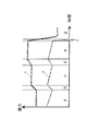
- FIG. 7 shows a tension state of the treatment instrument 1 of another example of the first embodiment.
- tension is applied to the wire 41 in the region a, the movement of the shaft 22 is stopped, the tension holding mode is set, and then the tissue T is peeled along the peeling line L by the peeling forceps K or the like.
- the tension A applied to the tension detection unit 62 is kept constant, but the tension B applied to the peeling line L gradually decreases as the peeled tissue increases. Therefore, in the region b, when the operator visually observes and determines that the tension of the peeling line is reduced, the tension is increased by the tension adjusting unit 6.
- the operation of peeling in the area c, adjusting the tension in the area d, and peeling in the area e are repeated. Finally, when the tissue is completely exfoliated in the region f, the tension is rapidly reduced.
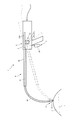
- FIG. 8 shows the treatment instrument 1 of the second embodiment.
- the treatment instrument 1 includes a case 21 and a main body 2 having a hollow shaft 22 provided in the case 21, a holding part 3 that holds a living tissue T in a body cavity, and a main body that is inserted into the shaft 22.
- the connecting portion 4 of the second embodiment is made of a bendable elastic member 42.
- the elastic member 42 can be taken in and out of the shaft 22 and can be made elastic by an elastic force.
- the elastic member 42 consists of a coil tube etc., and the wire 41 shown in FIG. 5 is inserted inside.
- the operation unit 5 includes a grip opening / closing operation member 52 that operates opening / closing of the grip unit 31.
- the grip opening / closing operation member 52 opens and closes the grip portion 31 by pushing and pulling the wire 41.
- the grip opening / closing operation member 52 is preferably constituted by a handle.
- the grasping portion 31 is inserted into the abdominal cavity through a trocar (not shown), and the grasping opening / closing operation member 52 is operated to open the grasping portion 31.
- the grasping portion 31 inserted into the abdominal cavity is closed by operating the grasping opening / closing operation member 52 after being applied to the tissue to be treated in the body, and grasps the tissue T as shown in FIG.
- FIG. 9 shows a state in which the treatment instrument 1 of the second embodiment is paying out the elastic member 42.
- the elastic member 42 is fed out with the grasping portion 31 grasping the tissue T.
- the elastic member 42 may be extended by driving the drive member 61a by operating the drive operation portion 61c and moving the moving member 61b.
- FIG. 10 shows a state in which the treatment tool 1 of the second embodiment is pulling the tissue T.
- the shaft 22 After extending the elastic member 42, the shaft 22 is lifted upward. Then, the movement of the shaft 22 is stopped at a position where the peeling line L of the tissue T can be confirmed by the endoscope.
- FIG. 11 shows a state where the treatment tool 1 of the second embodiment is peeling the tissue T.
- the tissue T is peeled along the peeling line L by the peeling forceps K or the like.
- the tissue T is gradually pulled up while being peeled by the elastic force of the elastic member 42, and the peeling line L is not hidden. .
- the tissue T can be accurately peeled off.
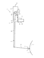
- FIG. 12 shows another method of using the treatment instrument 1 of the second embodiment.
- the treatment tool 1 according to the second embodiment can change the direction in which the tissue T is pulled by using the elastic force of the elastic member 42.
- the shaft 22 can be moved to the back, and the tissue T can be pulled by the grip portion 31 from the opposite side of the case 21. Therefore, a space can be formed on the front side of the tissue T, that is, the case 21 side, interference in the space can be reduced, and the peeling line L can be easily seen.
- FIG. 13 shows another method of using the treatment tool 1 of the second embodiment.
- the treatment tool 1 according to the second embodiment can adjust the pull-out amount of the elastic member 42. For example, as shown in FIG. 13, when the amount of the elastic member 42 pulled out is increased, a space can be formed on the front side of the tissue T, that is, the case 21 side, and interference in the space can be reduced. It becomes possible to make the peeling line L easy to see.
- FIG. 14 shows a treatment instrument according to the third embodiment.
- the treatment tool 1 according to the third embodiment forms the cross section of the elastic member 42 in an anisotropic shape. That is, the elastic member 42 of the third embodiment has a direction that is difficult to bend and a direction that is easy to bend, and the pulling direction of the tissue T can be changed by rotating the main body 2.
- the elastic member 42 of the third embodiment is formed in a flat shape that is longer in the X direction than in the Y direction, is less likely to bend in the X direction, and is easier to bend in the Y direction. is there.
- the elastic member 42 is formed with a hole 42a substantially at the center, and the wire 41 is inserted into the hole 42a.
- FIG. 15 shows a view of the treatment tool of the third embodiment as viewed from above.
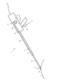
- FIG. 16 shows the treatment tool of the fourth embodiment.
- the treatment instrument 1 of the fourth embodiment is obtained by changing the tip of the holding unit 3 of the first embodiment to a hook 37.
- the hook 37 is inserted into the abdominal cavity through a trocar (not shown).
- the hook 37 inserted into the abdominal cavity is hooked on the tissue T to be treated in the body.
- the wire 41 is fed out with the hook 37 hooking the tissue T.
- the wire 41 may be fed by driving the drive member 61a by operating the drive operation unit 61c and moving the moving member 61b.
- the shaft 22 After unwinding the wire 41, the shaft 22 is lifted upward. Then, the movement of the shaft 22 is stopped at a position where the peeling line L of the tissue T can be confirmed by the endoscope. At that position, the tension holding mode operation member 51 is operated to set the tension holding mode. Then, after the movement of the shaft 22 is stopped and the tension holding mode is set, the tissue T is peeled along the peeling line L by the peeling forceps K or the like.
- the tissue T can be exfoliated accurately even in a narrow space.
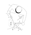
- FIG. 17 is a schematic diagram illustrating an example of a treatment using the treatment tool 1 of the present embodiment.
- FIG. 17 shows a state in which the endoscope 9 is inserted through the trocar 8b, the grip portion 31 and the like are inserted through the trocar 8a, and the peeling forceps K is inserted through the trocar 8d.
- An imaging unit and a visual field adjustment mechanism are provided at the distal end of the endoscope 9 inserted into the body cavity of the patient via the trocar 8b, and the angle and the like are adjusted so that the affected part or the holding part is included in the visual field. It is possible.
- the treatment instrument 1 inserted into the patient's body cavity via the trocar 8d is provided with a peeling forceps K.
- the practitioner M adjusts the visual field adjustment mechanism of the endoscope 9, and the affected area captured by the imaging unit is captured.
- the grasping portion 31 is opened and closed, and the affected area is treated with the peeling forceps K or the like.
- the main body 2 having the hollow shaft 22 provided in the case 21 and the case 21, the holding portion 3 that holds the living tissue in the body cavity, and the shaft 22 are inserted.
- the connection portion 4 for connecting the main body portion 2 and the holding portion 3 and the tension adjusting portion 6 that can adjust the tension of the connection portion 4 by moving the connection portion 4 with respect to the shaft 22 are provided.
- the tension of the connecting portion 4 that connects the holding portion 3 that holds the body and the main body portion 2 can be adjusted, the tissue T can be adjusted to an appropriate state, and an appropriate treatment can be performed. Interference can be avoided.
- the operation unit 5 that converts to the tension holding mode for holding the tension of the connection unit 4 is provided, and the tension adjustment unit 6 holds the tension of the connection unit 4 in the tension holding mode. Therefore, the tissue T can be held in an accurate state, and a more accurate treatment can be performed.
- the tension adjustment unit 6 is detected by the drive unit 61 provided in the case 21, the tension detection unit 62 that detects the tension of the connection unit 4, and the tension detection unit 62. Since it has the control part 63 which controls the drive part 61 based on a detected value, it becomes possible to always pull the connection part 4 with an appropriate tension, without moving the main-body part 2.
- FIG. 1 the tension adjustment unit 6 is detected by the drive unit 61 provided in the case 21, the tension detection unit 62 that detects the tension of the connection unit 4, and the tension detection unit 62. Since it has the control part 63 which controls the drive part 61 based on a detected value, it becomes possible to always pull the connection part 4 with an appropriate tension, without moving the main-body part 2.
- control unit 63 determines that the detection value detected by the tension detection unit 62 has changed abruptly per unit time, the control unit 63 stops the driving unit 61, so that the holding value is maintained. It is possible to prevent the part 3 from moving suddenly and damaging the body cavity.
- the control unit 63 detects the first detection value in which the tension detection unit 62 has suddenly decreased per unit time, and the drive unit 61 causes the connection unit 4 to shaft for a certain time.
- the second detection value detected by the tension detection unit 62 after the movement is compared with the first detection value, and when the increase amount is equal to or less than a predetermined amount, the drive unit 61 is stopped. Even when the holding unit 3 is detached from the tissue T, it is possible to prevent the body cavity from being damaged.
- connection part 4 since the connection part 4 has the wire 41, the space is formed in the front side of the structure
- connection portion 4 since the connection portion 4 includes the elastic member 42, a space is formed on the front side of the tissue T, that is, the case 21 side by extending the elastic member 42 from the shaft. It is possible to reduce the interference in the space and to make the tissue T easy to see.
- the elastic member 42 since the elastic member 42 has anisotropy, the position of the connecting portion 4 can be easily changed simply by twisting the case 21 around the axial direction of the shaft 22. It becomes possible.
- the holding unit 3 includes the gripping unit 31 for sandwiching the living tissue T, the tissue T can be accurately held with a simple structure.
- the holding unit 3 has the hook 37 for hooking the living tissue T, so that the tissue T can be accurately held even in a narrow space.
Landscapes
- Health & Medical Sciences (AREA)
- Surgery (AREA)
- Life Sciences & Earth Sciences (AREA)
- Engineering & Computer Science (AREA)
- Molecular Biology (AREA)
- Public Health (AREA)
- Heart & Thoracic Surgery (AREA)
- Medical Informatics (AREA)
- Nuclear Medicine, Radiotherapy & Molecular Imaging (AREA)
- Animal Behavior & Ethology (AREA)
- General Health & Medical Sciences (AREA)
- Biomedical Technology (AREA)
- Veterinary Medicine (AREA)
- Oral & Maxillofacial Surgery (AREA)
- Pathology (AREA)
- Robotics (AREA)
- Ophthalmology & Optometry (AREA)
- Surgical Instruments (AREA)
Priority Applications (4)
| Application Number | Priority Date | Filing Date | Title |
|---|---|---|---|
| JP2016573193A JP6325695B2 (ja) | 2015-02-02 | 2015-11-30 | 処置具 |
| EP15881192.7A EP3254629A4 (en) | 2015-02-02 | 2015-11-30 | Treatment instrument |
| CN201580075084.8A CN107205738B (zh) | 2015-02-02 | 2015-11-30 | 处置器具 |
| US15/661,065 US10420573B2 (en) | 2015-02-02 | 2017-07-27 | Surgical tool |
Applications Claiming Priority (2)
| Application Number | Priority Date | Filing Date | Title |
|---|---|---|---|
| JP2015-018368 | 2015-02-02 | ||
| JP2015018368 | 2015-02-02 |
Related Child Applications (1)
| Application Number | Title | Priority Date | Filing Date |
|---|---|---|---|
| US15/661,065 Continuation US10420573B2 (en) | 2015-02-02 | 2017-07-27 | Surgical tool |
Publications (1)
| Publication Number | Publication Date |
|---|---|
| WO2016125375A1 true WO2016125375A1 (ja) | 2016-08-11 |
Family
ID=56563732
Family Applications (1)
| Application Number | Title | Priority Date | Filing Date |
|---|---|---|---|
| PCT/JP2015/083641 WO2016125375A1 (ja) | 2015-02-02 | 2015-11-30 | 処置具 |
Country Status (5)
| Country | Link |
|---|---|
| US (1) | US10420573B2 (zh) |
| EP (1) | EP3254629A4 (zh) |
| JP (1) | JP6325695B2 (zh) |
| CN (1) | CN107205738B (zh) |
| WO (1) | WO2016125375A1 (zh) |
Cited By (2)
| Publication number | Priority date | Publication date | Assignee | Title |
|---|---|---|---|---|
| WO2019046025A1 (en) * | 2017-08-31 | 2019-03-07 | Carefusion 2200, Inc. | LAPAROSCOPIC INSTRUMENT WITH ADJUSTABLE LENGTH |
| WO2020110582A1 (ja) * | 2018-11-27 | 2020-06-04 | リバーフィールド株式会社 | 臓器リトラクタ |
Citations (3)
| Publication number | Priority date | Publication date | Assignee | Title |
|---|---|---|---|---|
| JP2000033071A (ja) * | 1998-07-17 | 2000-02-02 | Olympus Optical Co Ltd | 内視鏡治療装置 |
| JP2011239922A (ja) * | 2010-05-18 | 2011-12-01 | Olympus Corp | マニピュレータ |
| WO2014199759A1 (ja) * | 2013-06-11 | 2014-12-18 | オリンパスメディカルシステムズ株式会社 | 内視鏡用処置具 |
Family Cites Families (17)
| Publication number | Priority date | Publication date | Assignee | Title |
|---|---|---|---|---|
| US5938678A (en) * | 1997-06-11 | 1999-08-17 | Endius Incorporated | Surgical instrument |
| US6139563A (en) | 1997-09-25 | 2000-10-31 | Allegiance Corporation | Surgical device with malleable shaft |
| US6352503B1 (en) * | 1998-07-17 | 2002-03-05 | Olympus Optical Co., Ltd. | Endoscopic surgery apparatus |
| US8945095B2 (en) * | 2005-03-30 | 2015-02-03 | Intuitive Surgical Operations, Inc. | Force and torque sensing for surgical instruments |
| US8715270B2 (en) * | 2006-12-01 | 2014-05-06 | Boston Scientific Scimed, Inc. | Multi-part instrument systems and methods |
| US8870867B2 (en) * | 2008-02-06 | 2014-10-28 | Aesculap Ag | Articulable electrosurgical instrument with a stabilizable articulation actuator |
| JP2010035768A (ja) * | 2008-08-04 | 2010-02-18 | Olympus Medical Systems Corp | 能動駆動式医療機器 |
| JP5287087B2 (ja) * | 2008-09-25 | 2013-09-11 | 国立大学法人金沢大学 | 鉗子 |
| US20100114103A1 (en) * | 2008-11-06 | 2010-05-06 | The Regents Of The University Of California | Apparatus and methods for alteration of anatomical features |
| CN102123670B (zh) * | 2009-03-24 | 2014-03-19 | 奥林巴斯医疗株式会社 | 内窥镜处置用机器人系统 |
| JP5757496B2 (ja) * | 2009-12-24 | 2015-07-29 | 学校法人自治医科大学 | 皮膚吸着装置及び腹壁吊上装置 |
| WO2011108161A1 (ja) * | 2010-03-02 | 2011-09-09 | オリンパスメディカルシステムズ株式会社 | 医療システム及び制御方法 |
| WO2012153646A1 (ja) * | 2011-05-12 | 2012-11-15 | オリンパスメディカルシステムズ株式会社 | 医療用制御装置 |
| JP5816457B2 (ja) * | 2011-05-12 | 2015-11-18 | オリンパス株式会社 | 術具装置 |
| WO2015002655A1 (en) * | 2013-07-04 | 2015-01-08 | Empire Technology Development Llc | Freely-rotating minimally-invasive medical tool |
| JP6037964B2 (ja) * | 2013-07-26 | 2016-12-07 | オリンパス株式会社 | マニピュレータシステム |
| US9801679B2 (en) * | 2014-01-28 | 2017-10-31 | Ethicon Llc | Methods and devices for controlling motorized surgical devices |
-
2015
- 2015-11-30 CN CN201580075084.8A patent/CN107205738B/zh active Active
- 2015-11-30 WO PCT/JP2015/083641 patent/WO2016125375A1/ja active Application Filing
- 2015-11-30 JP JP2016573193A patent/JP6325695B2/ja active Active
- 2015-11-30 EP EP15881192.7A patent/EP3254629A4/en not_active Withdrawn
-
2017
- 2017-07-27 US US15/661,065 patent/US10420573B2/en active Active
Patent Citations (3)
| Publication number | Priority date | Publication date | Assignee | Title |
|---|---|---|---|---|
| JP2000033071A (ja) * | 1998-07-17 | 2000-02-02 | Olympus Optical Co Ltd | 内視鏡治療装置 |
| JP2011239922A (ja) * | 2010-05-18 | 2011-12-01 | Olympus Corp | マニピュレータ |
| WO2014199759A1 (ja) * | 2013-06-11 | 2014-12-18 | オリンパスメディカルシステムズ株式会社 | 内視鏡用処置具 |
Non-Patent Citations (1)
| Title |
|---|
| See also references of EP3254629A4 * |
Cited By (3)
| Publication number | Priority date | Publication date | Assignee | Title |
|---|---|---|---|---|
| WO2019046025A1 (en) * | 2017-08-31 | 2019-03-07 | Carefusion 2200, Inc. | LAPAROSCOPIC INSTRUMENT WITH ADJUSTABLE LENGTH |
| US10864006B2 (en) | 2017-08-31 | 2020-12-15 | Carefusion 2200, Inc. | Adjustable length laparoscopic instrument |
| WO2020110582A1 (ja) * | 2018-11-27 | 2020-06-04 | リバーフィールド株式会社 | 臓器リトラクタ |
Also Published As
| Publication number | Publication date |
|---|---|
| JP6325695B2 (ja) | 2018-05-16 |
| EP3254629A1 (en) | 2017-12-13 |
| CN107205738A (zh) | 2017-09-26 |
| JPWO2016125375A1 (ja) | 2017-04-27 |
| US10420573B2 (en) | 2019-09-24 |
| CN107205738B (zh) | 2020-07-14 |
| EP3254629A4 (en) | 2018-10-31 |
| US20170319223A1 (en) | 2017-11-09 |
Similar Documents
| Publication | Publication Date | Title |
|---|---|---|
| US8075474B2 (en) | Endoscope system and medical instrument | |
| US7780691B2 (en) | Endoscopic tissue resection device | |
| EP2142071B1 (en) | Steerable overtube | |
| US20140243799A1 (en) | Percutaneous Instrument with Tapered Shaft | |
| US20170080581A1 (en) | Manipulator control method, manipulator, and manipulator system | |
| US20100063437A1 (en) | Multifunctional surgical instrument | |
| JP7061166B2 (ja) | 内視鏡用システムの構成要素 | |
| JP2010022619A (ja) | 内視鏡用鉗子装置 | |
| JP2007089808A (ja) | 内視鏡システム | |
| US20230320724A1 (en) | Steerable suture retriever | |
| US9433342B2 (en) | Endoscopic instrument system | |
| WO2014157481A1 (ja) | 内視鏡下外科手術装置 | |
| JP5663088B2 (ja) | 鉗子及び鉗子ユニット | |
| JP2015139552A (ja) | 医療装置及び医療システム | |
| JP6325695B2 (ja) | 処置具 | |
| JP2019193764A (ja) | ワーキングチャネル案内要素を備えた装置 | |
| WO2017017753A1 (ja) | 組織回収具及び組織回収システム | |
| Chen et al. | Disposable endoscope tip actuation design and robotic platform | |
| WO2018070042A1 (ja) | 医療用器具および手術システム | |
| WO2018070040A1 (ja) | 把持機構 | |
| CN215458333U (zh) | 可视化的脏器管流定量监测与控制装置 | |
| JP2011067650A (ja) | 内視鏡用フード | |
| CN113100863A (zh) | 可视化的脏器管流定量监测与控制装置 |
Legal Events
| Date | Code | Title | Description |
|---|---|---|---|
| 121 | Ep: the epo has been informed by wipo that ep was designated in this application |
Ref document number: 15881192 Country of ref document: EP Kind code of ref document: A1 |
|
| ENP | Entry into the national phase |
Ref document number: 2016573193 Country of ref document: JP Kind code of ref document: A |
|
| REEP | Request for entry into the european phase |
Ref document number: 2015881192 Country of ref document: EP |
|
| NENP | Non-entry into the national phase |
Ref country code: DE |