WO2016121978A1 - Absorbent article and method for producing same - Google Patents
Absorbent article and method for producing same Download PDFInfo
- Publication number
- WO2016121978A1 WO2016121978A1 PCT/JP2016/052808 JP2016052808W WO2016121978A1 WO 2016121978 A1 WO2016121978 A1 WO 2016121978A1 JP 2016052808 W JP2016052808 W JP 2016052808W WO 2016121978 A1 WO2016121978 A1 WO 2016121978A1
- Authority
- WO
- WIPO (PCT)
- Prior art keywords
- stretchable
- sheet layer
- sheet
- elastic film
- absorbent article
- Prior art date
Links
Images


Classifications
-
- B—PERFORMING OPERATIONS; TRANSPORTING
- B29—WORKING OF PLASTICS; WORKING OF SUBSTANCES IN A PLASTIC STATE IN GENERAL
- B29C—SHAPING OR JOINING OF PLASTICS; SHAPING OF MATERIAL IN A PLASTIC STATE, NOT OTHERWISE PROVIDED FOR; AFTER-TREATMENT OF THE SHAPED PRODUCTS, e.g. REPAIRING
- B29C65/00—Joining or sealing of preformed parts, e.g. welding of plastics materials; Apparatus therefor
- B29C65/02—Joining or sealing of preformed parts, e.g. welding of plastics materials; Apparatus therefor by heating, with or without pressure
- B29C65/08—Joining or sealing of preformed parts, e.g. welding of plastics materials; Apparatus therefor by heating, with or without pressure using ultrasonic vibrations
- B29C65/083—Joining or sealing of preformed parts, e.g. welding of plastics materials; Apparatus therefor by heating, with or without pressure using ultrasonic vibrations using a rotary sonotrode or a rotary anvil
- B29C65/086—Joining or sealing of preformed parts, e.g. welding of plastics materials; Apparatus therefor by heating, with or without pressure using ultrasonic vibrations using a rotary sonotrode or a rotary anvil using a rotary anvil
-
- A—HUMAN NECESSITIES
- A61—MEDICAL OR VETERINARY SCIENCE; HYGIENE
- A61F—FILTERS IMPLANTABLE INTO BLOOD VESSELS; PROSTHESES; DEVICES PROVIDING PATENCY TO, OR PREVENTING COLLAPSING OF, TUBULAR STRUCTURES OF THE BODY, e.g. STENTS; ORTHOPAEDIC, NURSING OR CONTRACEPTIVE DEVICES; FOMENTATION; TREATMENT OR PROTECTION OF EYES OR EARS; BANDAGES, DRESSINGS OR ABSORBENT PADS; FIRST-AID KITS
- A61F13/00—Bandages or dressings; Absorbent pads
- A61F13/15—Absorbent pads, e.g. sanitary towels, swabs or tampons for external or internal application to the body; Supporting or fastening means therefor; Tampon applicators
- A61F13/45—Absorbent pads, e.g. sanitary towels, swabs or tampons for external or internal application to the body; Supporting or fastening means therefor; Tampon applicators characterised by the shape
- A61F13/49—Absorbent articles specially adapted to be worn around the waist, e.g. diapers
- A61F13/496—Absorbent articles specially adapted to be worn around the waist, e.g. diapers in the form of pants or briefs
-
- B—PERFORMING OPERATIONS; TRANSPORTING
- B29—WORKING OF PLASTICS; WORKING OF SUBSTANCES IN A PLASTIC STATE IN GENERAL
- B29C—SHAPING OR JOINING OF PLASTICS; SHAPING OF MATERIAL IN A PLASTIC STATE, NOT OTHERWISE PROVIDED FOR; AFTER-TREATMENT OF THE SHAPED PRODUCTS, e.g. REPAIRING
- B29C65/00—Joining or sealing of preformed parts, e.g. welding of plastics materials; Apparatus therefor
- B29C65/82—Testing the joint
- B29C65/8253—Testing the joint by the use of waves or particle radiation, e.g. visual examination, scanning electron microscopy, or X-rays
-
- B—PERFORMING OPERATIONS; TRANSPORTING
- B29—WORKING OF PLASTICS; WORKING OF SUBSTANCES IN A PLASTIC STATE IN GENERAL
- B29C—SHAPING OR JOINING OF PLASTICS; SHAPING OF MATERIAL IN A PLASTIC STATE, NOT OTHERWISE PROVIDED FOR; AFTER-TREATMENT OF THE SHAPED PRODUCTS, e.g. REPAIRING
- B29C66/00—General aspects of processes or apparatus for joining preformed parts
- B29C66/01—General aspects dealing with the joint area or with the area to be joined
- B29C66/05—Particular design of joint configurations
- B29C66/10—Particular design of joint configurations particular design of the joint cross-sections
- B29C66/11—Joint cross-sections comprising a single joint-segment, i.e. one of the parts to be joined comprising a single joint-segment in the joint cross-section
- B29C66/112—Single lapped joints
- B29C66/1122—Single lap to lap joints, i.e. overlap joints
-
- B—PERFORMING OPERATIONS; TRANSPORTING
- B29—WORKING OF PLASTICS; WORKING OF SUBSTANCES IN A PLASTIC STATE IN GENERAL
- B29C—SHAPING OR JOINING OF PLASTICS; SHAPING OF MATERIAL IN A PLASTIC STATE, NOT OTHERWISE PROVIDED FOR; AFTER-TREATMENT OF THE SHAPED PRODUCTS, e.g. REPAIRING
- B29C66/00—General aspects of processes or apparatus for joining preformed parts
- B29C66/01—General aspects dealing with the joint area or with the area to be joined
- B29C66/05—Particular design of joint configurations
- B29C66/20—Particular design of joint configurations particular design of the joint lines, e.g. of the weld lines
- B29C66/21—Particular design of joint configurations particular design of the joint lines, e.g. of the weld lines said joint lines being formed by a single dot or dash or by several dots or dashes, i.e. spot joining or spot welding
-
- B—PERFORMING OPERATIONS; TRANSPORTING
- B29—WORKING OF PLASTICS; WORKING OF SUBSTANCES IN A PLASTIC STATE IN GENERAL
- B29C—SHAPING OR JOINING OF PLASTICS; SHAPING OF MATERIAL IN A PLASTIC STATE, NOT OTHERWISE PROVIDED FOR; AFTER-TREATMENT OF THE SHAPED PRODUCTS, e.g. REPAIRING
- B29C66/00—General aspects of processes or apparatus for joining preformed parts
- B29C66/40—General aspects of joining substantially flat articles, e.g. plates, sheets or web-like materials; Making flat seams in tubular or hollow articles; Joining single elements to substantially flat surfaces
- B29C66/41—Joining substantially flat articles ; Making flat seams in tubular or hollow articles
- B29C66/43—Joining a relatively small portion of the surface of said articles
- B29C66/433—Casing-in, i.e. enclosing an element between two sheets by an outlined seam
-
- B—PERFORMING OPERATIONS; TRANSPORTING
- B29—WORKING OF PLASTICS; WORKING OF SUBSTANCES IN A PLASTIC STATE IN GENERAL
- B29C—SHAPING OR JOINING OF PLASTICS; SHAPING OF MATERIAL IN A PLASTIC STATE, NOT OTHERWISE PROVIDED FOR; AFTER-TREATMENT OF THE SHAPED PRODUCTS, e.g. REPAIRING
- B29C66/00—General aspects of processes or apparatus for joining preformed parts
- B29C66/70—General aspects of processes or apparatus for joining preformed parts characterised by the composition, physical properties or the structure of the material of the parts to be joined; Joining with non-plastics material
- B29C66/72—General aspects of processes or apparatus for joining preformed parts characterised by the composition, physical properties or the structure of the material of the parts to be joined; Joining with non-plastics material characterised by the structure of the material of the parts to be joined
- B29C66/729—Textile or other fibrous material made from plastics
- B29C66/7294—Non woven mats, e.g. felt
-
- B—PERFORMING OPERATIONS; TRANSPORTING
- B29—WORKING OF PLASTICS; WORKING OF SUBSTANCES IN A PLASTIC STATE IN GENERAL
- B29C—SHAPING OR JOINING OF PLASTICS; SHAPING OF MATERIAL IN A PLASTIC STATE, NOT OTHERWISE PROVIDED FOR; AFTER-TREATMENT OF THE SHAPED PRODUCTS, e.g. REPAIRING
- B29C66/00—General aspects of processes or apparatus for joining preformed parts
- B29C66/80—General aspects of machine operations or constructions and parts thereof
- B29C66/81—General aspects of the pressing elements, i.e. the elements applying pressure on the parts to be joined in the area to be joined, e.g. the welding jaws or clamps
- B29C66/814—General aspects of the pressing elements, i.e. the elements applying pressure on the parts to be joined in the area to be joined, e.g. the welding jaws or clamps characterised by the design of the pressing elements, e.g. of the welding jaws or clamps
- B29C66/8141—General aspects of the pressing elements, i.e. the elements applying pressure on the parts to be joined in the area to be joined, e.g. the welding jaws or clamps characterised by the design of the pressing elements, e.g. of the welding jaws or clamps characterised by the surface geometry of the part of the pressing elements, e.g. welding jaws or clamps, coming into contact with the parts to be joined
- B29C66/81427—General aspects of the pressing elements, i.e. the elements applying pressure on the parts to be joined in the area to be joined, e.g. the welding jaws or clamps characterised by the design of the pressing elements, e.g. of the welding jaws or clamps characterised by the surface geometry of the part of the pressing elements, e.g. welding jaws or clamps, coming into contact with the parts to be joined comprising a single ridge, e.g. for making a weakening line; comprising a single tooth
- B29C66/81429—General aspects of the pressing elements, i.e. the elements applying pressure on the parts to be joined in the area to be joined, e.g. the welding jaws or clamps characterised by the design of the pressing elements, e.g. of the welding jaws or clamps characterised by the surface geometry of the part of the pressing elements, e.g. welding jaws or clamps, coming into contact with the parts to be joined comprising a single ridge, e.g. for making a weakening line; comprising a single tooth comprising a single tooth
-
- B—PERFORMING OPERATIONS; TRANSPORTING
- B29—WORKING OF PLASTICS; WORKING OF SUBSTANCES IN A PLASTIC STATE IN GENERAL
- B29C—SHAPING OR JOINING OF PLASTICS; SHAPING OF MATERIAL IN A PLASTIC STATE, NOT OTHERWISE PROVIDED FOR; AFTER-TREATMENT OF THE SHAPED PRODUCTS, e.g. REPAIRING
- B29C66/00—General aspects of processes or apparatus for joining preformed parts
- B29C66/80—General aspects of machine operations or constructions and parts thereof
- B29C66/81—General aspects of the pressing elements, i.e. the elements applying pressure on the parts to be joined in the area to be joined, e.g. the welding jaws or clamps
- B29C66/814—General aspects of the pressing elements, i.e. the elements applying pressure on the parts to be joined in the area to be joined, e.g. the welding jaws or clamps characterised by the design of the pressing elements, e.g. of the welding jaws or clamps
- B29C66/8141—General aspects of the pressing elements, i.e. the elements applying pressure on the parts to be joined in the area to be joined, e.g. the welding jaws or clamps characterised by the design of the pressing elements, e.g. of the welding jaws or clamps characterised by the surface geometry of the part of the pressing elements, e.g. welding jaws or clamps, coming into contact with the parts to be joined
- B29C66/81433—General aspects of the pressing elements, i.e. the elements applying pressure on the parts to be joined in the area to be joined, e.g. the welding jaws or clamps characterised by the design of the pressing elements, e.g. of the welding jaws or clamps characterised by the surface geometry of the part of the pressing elements, e.g. welding jaws or clamps, coming into contact with the parts to be joined being toothed, i.e. comprising several teeth or pins, or being patterned
-
- B—PERFORMING OPERATIONS; TRANSPORTING
- B29—WORKING OF PLASTICS; WORKING OF SUBSTANCES IN A PLASTIC STATE IN GENERAL
- B29C—SHAPING OR JOINING OF PLASTICS; SHAPING OF MATERIAL IN A PLASTIC STATE, NOT OTHERWISE PROVIDED FOR; AFTER-TREATMENT OF THE SHAPED PRODUCTS, e.g. REPAIRING
- B29C66/00—General aspects of processes or apparatus for joining preformed parts
- B29C66/80—General aspects of machine operations or constructions and parts thereof
- B29C66/83—General aspects of machine operations or constructions and parts thereof characterised by the movement of the joining or pressing tools
- B29C66/834—General aspects of machine operations or constructions and parts thereof characterised by the movement of the joining or pressing tools moving with the parts to be joined
- B29C66/8341—Roller, cylinder or drum types; Band or belt types; Ball types
- B29C66/83411—Roller, cylinder or drum types
- B29C66/83413—Roller, cylinder or drum types cooperating rollers, cylinders or drums
-
- B—PERFORMING OPERATIONS; TRANSPORTING
- B29—WORKING OF PLASTICS; WORKING OF SUBSTANCES IN A PLASTIC STATE IN GENERAL
- B29C—SHAPING OR JOINING OF PLASTICS; SHAPING OF MATERIAL IN A PLASTIC STATE, NOT OTHERWISE PROVIDED FOR; AFTER-TREATMENT OF THE SHAPED PRODUCTS, e.g. REPAIRING
- B29C66/00—General aspects of processes or apparatus for joining preformed parts
- B29C66/80—General aspects of machine operations or constructions and parts thereof
- B29C66/83—General aspects of machine operations or constructions and parts thereof characterised by the movement of the joining or pressing tools
- B29C66/834—General aspects of machine operations or constructions and parts thereof characterised by the movement of the joining or pressing tools moving with the parts to be joined
- B29C66/8341—Roller, cylinder or drum types; Band or belt types; Ball types
- B29C66/83411—Roller, cylinder or drum types
- B29C66/83415—Roller, cylinder or drum types the contact angle between said rollers, cylinders or drums and said parts to be joined being a non-zero angle
-
- B—PERFORMING OPERATIONS; TRANSPORTING
- B29—WORKING OF PLASTICS; WORKING OF SUBSTANCES IN A PLASTIC STATE IN GENERAL
- B29C—SHAPING OR JOINING OF PLASTICS; SHAPING OF MATERIAL IN A PLASTIC STATE, NOT OTHERWISE PROVIDED FOR; AFTER-TREATMENT OF THE SHAPED PRODUCTS, e.g. REPAIRING
- B29C66/00—General aspects of processes or apparatus for joining preformed parts
- B29C66/80—General aspects of machine operations or constructions and parts thereof
- B29C66/83—General aspects of machine operations or constructions and parts thereof characterised by the movement of the joining or pressing tools
- B29C66/834—General aspects of machine operations or constructions and parts thereof characterised by the movement of the joining or pressing tools moving with the parts to be joined
- B29C66/8351—Jaws mounted on rollers, cylinders, drums, bands, belts or chains; Flying jaws
- B29C66/83511—Jaws mounted on rollers, cylinders, drums, bands, belts or chains; Flying jaws jaws mounted on rollers, cylinders or drums
-
- B—PERFORMING OPERATIONS; TRANSPORTING
- B29—WORKING OF PLASTICS; WORKING OF SUBSTANCES IN A PLASTIC STATE IN GENERAL
- B29L—INDEXING SCHEME ASSOCIATED WITH SUBCLASS B29C, RELATING TO PARTICULAR ARTICLES
- B29L2031/00—Other particular articles
- B29L2031/48—Wearing apparel
- B29L2031/4871—Underwear
- B29L2031/4878—Diapers, napkins
Definitions
- the present invention relates to an absorbent article provided with an elastic sheet in which a first sheet layer and a second sheet layer sandwich an elastic film, and a method for manufacturing the same.
- an absorbent article for example, a disposable diaper
- stretchability in order to improve fit to the body surface, it is common to impart stretchability to appropriate places such as around the legs and around the trunk.
- a method for imparting stretchability conventionally, a method of fixing an elongated elastic stretchable member such as rubber thread in a stretched state in the longitudinal direction has been widely adopted, but it is desired to impart stretchability to a certain width. In such a case, a mode is adopted in which the rubber thread is fixed in a state of being arranged side by side with an interval in width.
- a non-woven fabric / elastomer film / non-woven fabric is also used as a material that gives a stretch property by pressing in a planar shape and considering the touch.
- a non-woven fabric / elastomer film / non-woven fabric is also used as a material that gives a stretch property by pressing in a planar shape and considering the touch.
- the thing of patent document 1 supplies the elastic film which expands-contracts in the continuous MD direction (machine direction) where melting
- the stretchable sheet according to Patent Document 1 is intended for continuous production, the pattern of the raised portions in the heat bonding roller forming the joint is uniform in the width direction and the circumferential direction. Even if the position in the width direction is different, the stretching stress is uniform. Therefore, it is difficult to say that this stretchable sheet is widely used.
- a main problem of the present invention is to provide an absorbent article including an elastic sheet having an elastic part having different elastic stress depending on the position in the region of the elastic sheet.
- the present invention that has solved the above problems is as follows.
- the absorptive article of the present invention is provided with the elastic sheet which has the elastic part which can be expanded and contracted at least in one direction.
- an elastic film stretchable in one direction is laminated between a first sheet layer made of non-woven fabric that does not have stretchability and a second sheet layer made of non-woven fabric that does not have stretchability.
- the first sheet layer and the second sheet layer are joined at a large number of joints that are spaced apart, either directly or via an elastic film.
- the expansion / contraction part contracts by the contraction force of the elastic film, and can expand when an external force is applied in the one direction.
- the stretchable stress is different because the joint area ratio occupied by the total area of the joints included in the unit area is different in the one direction.
- the direction of the difference in the stretching stress can be appropriately selected depending on the arrangement form of the stretchable part. For example, when applied to the waist or waist of a disposable diaper, it is applied as a stretchable one in the direction, that is, the one direction. Is applied as a waist circumference or waist circumference direction, and the stretching stress in one direction is made different.
- the one direction is applied as the front-rear direction, and the stretching stress in the direction orthogonal to the one direction (orthogonal direction) is different. There is a mode to make it.
- the arrangement pattern of the joint is not limited.
- One example is a staggered arrangement that exhibits a good appearance.
- An elastic film that can be expanded and contracted in the one direction and the orthogonal direction can be used.
- an elastic film stretchable in the one direction and the orthogonal direction is laminated between the first sheet layer not having stretchability and the second sheet layer not having stretchability, and The first sheet layer and the second sheet layer are joined at a large number of joints at intervals, directly or via an elastic film,
- the stretchable part contracts due to the contraction force of the elastic film, and is extensible when an external force is applied in the one direction and the orthogonal direction,
- an absorbent article having different stretch stresses by having a joint area ratio occupied by a total area of the joints included in a unit area at least in the one direction. Is done.
- the difference in elastic film strength occurs between the joined part and the non-joined part. Therefore, after the stretched state of the stretch sheet holding the extension is once released and contracted to make a product; or after the stretch sheet holding the stretch is combined with another member, the stretched state is once released and contracted When the product is stretched mechanically or manually in the expansion / contraction direction, breakage occurs at the boundary between the joined portion and the non-joined portion. As a result, a through hole is formed.
- the absorbent article includes an elastic sheet having an elastic part that can expand and contract in at least one direction, and in the elastic part, the first sheet layer that does not have elasticity and the second that does not have elasticity.
- the elastic film which can be expanded and contracted in at least one direction is laminated between the sheet layer, and the first sheet layer and the second sheet layer are a large number of spaced joints, and the elastic film It becomes the aspect formed by joining through the through-hole formed in the film.
- the through hole there is an advantage that air permeability is ensured.
- the through holes do not need to be formed in all the joints, and exhibit air permeability even if formed in some of the joints.
- the through hole When the elastic film can expand and contract in only one direction, the through hole has a shape extending in one direction from the edge of the joint.
- the through hole When the elastic film can be expanded and contracted in both the one direction and the orthogonal direction, the through hole has a shape extending in both directions from the edge of the joint portion, and in some cases, may have an annular shape around the joint portion.
- the elastic film of the present invention can be stretched in one direction and can be stretched in one direction and an orthogonal direction.
- An absorbent article comprising a stretchable sheet having a stretchable part that is stretchable in at least one direction, In the stretchable part, an elastic film stretchable in the one direction and the orthogonal direction is laminated between a first sheet layer that does not have stretchability and a second sheet layer that does not have stretchability, and The first sheet layer and the second sheet layer are joined and formed through a through-hole formed in the elastic film at a number of joining portions spaced apart in the one direction and the orthogonal direction, respectively.
- the stretchable part contracts due to the contraction force of the elastic film, and can be extended by applying an external force in the one direction and the orthogonal direction,
- the joint area ratio occupied by the total area of the joints included in a unit area is different in the one direction, so that the stretch stress in the one direction is different
- the absorbent article is characterized in that the expansion and contraction stress in the orthogonal direction is different due to the fact that the joint area ratio is different in the orthogonal direction.
- the joint is provided with a configuration in which the length in the orthogonal direction is longer than the length in the one direction.
- a disposable diaper having the stretchable region extending and contracting at least in the waistline direction in the waistline region, and the contact pressure of the stretchable region measured by a contact pressure measurement test is 0.3 over the entire range of a circumferential length of 60 to 95 cm.
- a form is also provided that is ⁇ 1.2 kPa.
- thread rubber a large number of thread rubbers are placed at intervals in the direction perpendicular to the stretch direction, ensuring a surface fit.
- the contact pressure is increased to the same level as the underwear, tightening may be felt tightly or the rubber band may be marked on the skin. Therefore, conventionally, the contact pressure is lower than that of underwear, and it has been a problem that a slippage due to movement is likely to occur.
- the expansion / contraction part contracts due to the contraction force of the elastic film, and can expand when an external force is applied in the front-rear direction.
- the joint area ratio occupied by the total area of the joints included in the unit area is different in the width direction, so that the stretch stress in the front-rear direction is different between the width directions.
- the stretchable part formed on both sides of the absorbent article is formed in the middle in the front-rear direction, and it can be a region that does not exhibit stretchability or has low stretchability up to the end in the front-rear direction.
- the stretchable part formed on both sides of the absorbent article may be linear or curved.
- a disposable diaper may draw a constricted curve toward the center in the width direction in the crotch area.
- the said expansion-contraction part formed in the both sides of the absorbent article it can be set as the structure from which the junction part area ratio differs in the front-back direction.
- the joint area ratio is different in the front-rear direction, and the joint area ratio increases toward the edge at least in the front-rear direction edge side of the stretchable part. It can be adopted.
- the central part of the stretchable part strengthens the stretch force and weakens the stretch force from there toward the end, thereby preventing the diaper end from becoming easily rounded, and also has the advantage of improving wearability to the wearer. .
- the structure may be such that the joint area ratio is different in the width direction.
- the width direction side edge of the stretchable part has a high bonding area ratio of the wrinkles and the width direction center has a low bonding area ratio of the wrinkles.
- the outer shape of the diaper is easily rounded in the cross section and the fitting property is improved.
- the second aspect is a configuration in which the widthwise side edge of the stretchable portion has a low bonding area ratio of the folds and the width direction center has a high bonding area ratio of the folds. In this case, there is an advantage that the tightening force at the crotch portion is high for a person with thick legs.
- the stretchable sheet of the present invention holes penetrating the first sheet layer and the second sheet layer are not formed. This point is different from the stretchable sheet shown in FIG. 5 or 7 of Japanese Patent No. 4562391.
- the first sheet layer and the second sheet layer may be joined through through holes formed in the elastic film at a large number of joints spaced apart. That is, a through hole may be formed in the elastic film.
- An absorptive article provided with an elastic sheet which has an elastic part which can expand and contract at least in one direction can be manufactured by the following method.
- the elastic film is interposed between the first sheet layer and the second sheet layer, and is spaced from the outside of the first sheet layer and the second sheet layer by a heat melting device.
- the elastic film is provided with heat melting energy by a large number of heat melting portions opened to melt the elastic film, and the first sheet layer and the second sheet layer can be directly connected to the elastic film through the elastic film.
- Joining process of joining with, Including the stretchable part is formed in which no hole is formed in the entire joint area and the first sheet layer and the second sheet layer remain.
- the elastic film is passed through a nip roll step in which a pair of opposing nips are arranged in the front-rear direction, and the elastic speed is increased by increasing the peripheral speed of the front nip roll step relative to the peripheral speed of the rear nip roll step between the front and rear nip roll steps.
- a method is provided for feeding a film to the feeding step in a stretched state.
- the heat melting apparatus has an anvil roll and an ultrasonic horn, and the anvil roll has a plurality of protrusions formed on the outer surface thereof spaced apart in the roll length direction and the outer peripheral direction.
- the aspect which comprises the said thermal fusion part with an ultrasonic horn is provided.
- the ultrasonic heat melting apparatus other heat melting means may be used.
- the melting point of the elastic film is lower than the melting point of the first sheet layer made of nonwoven fabric and the melting point of the second sheet layer made of nonwoven fabric, higher than this melting point, and lower than the melting points of the first sheet layer and the second sheet layer.
- the melting energy corresponding to the temperature is applied, the elastic film is melted by heat, while the first sheet layer and the second sheet layer are not melted at all or are partially melted. As a result, holes are formed in the entire joint region. The first sheet layer and the second sheet layer remain. However, the line speed at the time of manufacturing the elastic sheet is high.
- the elastic film preferably has a melting point of about 80 to 145 ° C.
- the first sheet layer and the second sheet layer preferably have a melting point of about 85 to 190 ° C., particularly about 130 to 190 ° C.
- the difference between the melting points of the first sheet layer and the second sheet layer and the melting point of the elastic film 30 having a lower melting point is preferably about 50 to 80 ° C.
- the melting point of the elastic film is 95 to 125 ° C.
- the melting point of the first sheet layer is more than 125 ° C. to 160 ° C., more preferably 130 to 160 ° C.
- the melting point of the second sheet layer is 125. More than 160 ° C. to 160 ° C., more preferably 130 to 160 ° C.
- the area of the joint portion in the stretchable region is 0.14 to 3.5 mm 2
- the area of the opening of the through hole in the natural length state is 1 to 1 of the area of the joint portion.
- the area ratio of the joint in the stretchable region is 1.8 to 22.5%.
- the “area ratio” means the ratio of the target portion to the unit area, and the total area of the target portion (for example, joints and openings of through holes) in the target region (for example, the stretchable region) is the area of the target region.
- the “joint area ratio” means the area ratio in a state of being stretched to the elastic limit in the stretching direction.
- the area of the opening of the through hole means a value in a state in which the stretchable structure is in a natural length, and the area of the opening of the through hole is not uniform in the thickness direction, such as different between the front and back of the elastic film. Means the minimum value.
- the joint area ratio in the present specification can be selected by selecting the size, shape, separation interval, arrangement pattern in the roll length direction and roll circumferential direction, etc. of the protrusions of the anvil roll described later.
- “Elongation stress” is measured by a tensile test according to JIS K7127: 1999 “Plastics—Test method for tensile properties—” with an initial chuck interval (distance between marked lines) of 50 mm and a tensile speed of 300 mm / min. It means “stress when stretched to 50% of elastic limit (N / 35 mm)”.
- the test piece is created with a width that can be cut out, and the measured value is set to a value converted into a width of 35 mm. If the target area is small and sufficient specimens cannot be collected, a comparatively small specimen can be compared at least if it is a comparison of stretching stress.
- an absorbent article including an elastic sheet having an elastic part having different elastic stress depending on the position in the region of the elastic sheet.
- FIG. 3 is a plan view of a main part of the exterior body.
- FIG. 1 is a CC cross-sectional view of FIG. 1, and (b) is an EE cross-sectional view of FIG.
- FIG. 2 is a cross-sectional view taken along the line AA in FIG.
- FIG. 3 is a cross-sectional view taken along the line BB in FIG.
- It is a top view which shows only the principal part of the underpants type disposable diaper of a full expansion
- the absorbent article of the present invention means a product that absorbs and retains body fluids such as disposable diapers, sanitary napkins, and absorbent pads.
- the absorbent article has a stretchable part that can be stretched in at least one direction. As this one direction, in a disposable diaper, it is typically a waist direction (width direction in a product). In addition to the one direction, it is also possible to extend and contract in a direction perpendicular to this (the front-rear direction in a disposable diaper).
- the stretchable portion is formed between a first sheet layer 21 made of, for example, a non-woven fabric that does not have stretchability, and a second sheet layer 22 made of, for example, a non-woven fabric that does not have stretchability.
- the elastic film 30 that can be expanded and contracted in the one direction is laminated, and the first sheet layer 21 and the second sheet layer 22 are directly or via the elastic film 30 with a large number of intervals. 40 is joined.
- “the first sheet layer 21 and the second sheet layer 22 are not stretchable” does not mean that the first sheet layer 21 and the second sheet layer 22 are not stretched at all. It means not.
- the first sheet layer 21, the elastic film 30, and the second sheet are disposed between the anvil roll 60 having the protrusions 60 a formed in a predetermined pattern on the outer surface and the ultrasonic horn 61.
- the layer 22 is supplied, and ultrasonic melting energy is applied by the ultrasonic horn 61.
- the elastic film 30 is mainly melted to join the first sheet layer 21 and the second sheet layer 22. The joining form will be described in detail later.
- the elongation rate in the manufacturing process of the elastic film 30 (based on the length of the natural state being 100%) is, for example, that the peripheral speed of the driving anvil roll 60 is faster than the peripheral speed of the rear driving roll 62. It can be set by selecting the speed difference between the rolls.
- 63 is a guide roller.
- FIG. 8 schematically shows a cross section of the stretchable sheet after joining in the stretched state.
- the stretchable sheet contracts due to the contraction force of the elastic film 30 and can be stretched when an external force is applied in one direction (left-right direction in FIG. 9). Therefore, when this stretchable sheet is used, for example, in the waist circumference direction of a disposable diaper, the waist or waist is contracted.
- an elastic sheet can be manufactured with a predetermined area, when it is desired to apply a contracting force to the entire desired area, the elastic sheet may be applied.
- it is common to fix a plurality of thread rubbers in parallel on a sheet, but this is due to deterioration of hot rubber adhesive for fixing to thread rubbers and sheets. It is inferior in terms of quality deterioration and stable productivity during production.
- the first sheet layer 21 and the second sheet layer 22 are joined by melting the elastic film 30.
- the bonding mode between the layers is not limited to these examples.
- the first sheet layer 21 and the second sheet layer 22 are joined directly, that is, without interposing an elastic film.
- the above aspects (1) to (3) are cases where the melting point of the elastic film 30 is lower than the melting points of the first sheet layer 21 and the second sheet layer 22, but the melting point of the elastic film 30 is the first sheet layer. 21 and / or higher than the melting point of the second sheet layer 22.
- the elastic film 30 side surface portion of the first sheet layer 21 and / or the second sheet layer 22 is activated or melted and joined to the elastic film 30.
- the elastic film 30 may be partly melted, and the first sheet layer 21 and / or the second sheet layer 22 may be joined by melting.
- the 1st sheet layer 21 and / or the 2nd sheet layer 22 are nonwoven fabrics, and the fiber may have a core-sheath structure. In this case, for example, only the sheath component of the fiber can be melted and contribute to the joining.
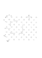
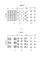
- the main feature of the present invention is that, in the region of the stretchable sheet, the joint area ratio occupied by the total area of the joints included in the unit area is different in at least one direction, so that the stretching stress is reduced. It is a difference.
- the junction area ratio is a percentage of the total area of the junctions 40, 40... Included in the unit area S in the unit area S, as shown in FIG. .
- the unit area S in this case is desirably set to a size that includes 10 or more joints (it is difficult to compare the stretching stress with a small number).
- 13 joint portions are included.
- the external shape which defines unit area S may be other shapes, such as a rectangle and a circle, besides a square.
- An example of the joint 40 is a circle shown in FIG. Of course, the shape may be an ellipse or a rectangle. In FIG.
- Lm is the arrangement interval length in the machine direction (MD direction)
- Lc is the arrangement interval length in the orthogonal direction (cross direction) orthogonal to the machine direction
- Pm is the pitch length in the machine direction
- Pc is the orthogonal direction (cross direction: CD) pitch length.
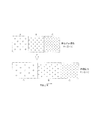
- FIG. 2 shows that the area A, B, and C have a joint area ratio of A ⁇ B ⁇ C so that the stretching stress is in the relationship of A>B> C.
- A when the pitch length Pm and the pitch length Pc are long and A is compared with the case C when the pitch length Pm and the pitch length Pc are short, a case where the pitch length Pm ⁇ Pc is long is A (when the joint area ratio is low).
- the pitch length Pm ⁇ Pc is short, the elongation ratio is larger than in C (when the joint area ratio is high).
- the stretching stress has a relationship of A>B> C.
- B is the case of the middle case.
- the extensional stress in the lateral direction of FIG. 2 is different for each region. Therefore, when the absorbent article is worn, the contraction force is different for each region, which is useful.
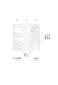
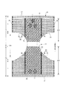
- FIG. 3 shows an example in which the stretching stress in the intermediate region B in the horizontal direction is made smaller than those in the regions A and A on both sides.
- This example can be used as a seat around the waist of a disposable diaper, and the intermediate region B where the absorbent body is present reduces the stretching stress, and gives sufficient stretching stress in both side regions A and A to wear the disposable diaper. This is effective for comfortably fitting a person.
- the horizontal direction on the drawing is the width direction (CD direction) of the absorbent article
- the vertical direction on the drawing is the front-rear direction (MD direction) of the absorbent article. It is an example made different in the width direction (CD direction).
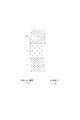
- the horizontal direction on the drawing is the width direction (CD direction) of the absorbent article
- the vertical direction on the drawing is the front-back direction (MD direction) of the absorbent article. It is the example which made the up-down direction differ in the front-back direction (MD direction) of an absorbent article.
- the difference in the joint area ratio can be achieved by changing the joint area in addition to the density of the arrangement pattern.
- FIG. 6 shows an example in which a large number of small junctions are arranged in the region E and the junction area ratio is the same as that of the region D.
- the elastic film in the present invention may be stretchable in only one direction, but a two-way stretchable film that stretches in a direction perpendicular to the direction is also suitable.
- the thickness, material, strain / stress characteristics, and melting point of the elastic film can be selected as appropriate.
- the ultrasonic melting energy applied thereto, and the elongation rate of the elastic film during the production of the elastic sheet as shown in FIG.
- Through-holes 31 can be formed around the periphery.
- the nonwoven fabric exhibits air permeability. Therefore, for example, when it is used as a member around the waist of a disposable diaper, it becomes a waist sheet with good breathability.
- the reason why the ventilation through hole 31 is formed is not necessarily clear, but the elastic film 30 is melted by the ultrasonic melting energy, and the coupling portion 40 is thinned by the pressing by the projection 60 a of the anvil roll 60. . At this time, the elastic film 30 is also thinned, the peripheral portion of the joint portion 40 reaches the breaking strength, the breakage is started by the stretching stress acting on the stretched elastic film 3, shrinks to the balance point, and opens. it is conceivable that.
- FIG. 12 schematically shows an example of forming the through hole 31 in the case of a circular through hole.
- the crescent-shaped through holes 31 are formed on both sides of the connecting portion 40 in the machine direction (extension direction).
- the connecting part can be formed in a long shape in a direction (cross direction: CD direction) orthogonal to the machine direction (extension direction).
- cross direction CD direction
- extension direction the machine direction
- the through holes 31 are formed in all the coupling portions. If it is required to reliably form the through hole 31 or make a large opening, the method shown in FIG. 14 can be adopted. That is, as shown in FIG. 14B, the stretchable sheet in which the coupling portion 40 is formed is passed between a pair of rolls 64 having protrusions or protrusions 64a, and between the adjacent protrusions 64a and 64a of one roll 64.
- the through-hole 31 can be formed by biting the protrusion 64a of the other roll 64 and applying a deformation force to the stretchable sheet.
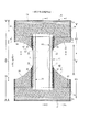
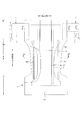
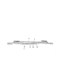
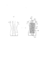
- This pants-type disposable diaper (hereinafter also simply referred to as a diaper) has an exterior body 20 that forms a front body Fr and a back body Ba, and an interior body 10 that is fixed to and integrated with the inner surface of the exterior body 20.
- the interior body 10 is formed by interposing an absorbent body 13 between a liquid-permeable top sheet 11 and a liquid-impermeable back sheet 12.
- a joining means such as a hot melt adhesive (shaded portion 10B in FIG. 21), the interior body 10 and the exterior body 20 are joined.
- a pants-type disposable diaper having a waist opening and a pair of left and right leg openings is formed.
- the interior body 10 has an absorbent body 13 interposed between a liquid-permeable top sheet 11 made of nonwoven fabric or the like and a liquid-impermeable back side sheet 12 made of polyethylene or the like.
- the excretory fluid that has permeated through the top sheet 11 is absorbed and retained.
- the planar shape of the interior body 10 is not particularly limited, but is generally rectangular as illustrated.
- a porous or non-porous nonwoven fabric or a porous plastic sheet is preferably used as the liquid-permeable surface sheet 11 covering the surface side (skin contact surface side) of the absorbent body 13.
- the material fibers constituting the nonwoven fabric can be made of synthetic fibers such as polyethylene or polypropylene, synthetic fibers such as polyester or polyamide, recycled fibers such as rayon or cupra, natural fibers such as cotton, and the spunlace method.
- a nonwoven fabric obtained by an appropriate processing method such as a spun bond method, a thermal bond method, a melt blown method, or a needle punch method can be used. Among these processing methods, the spunlace method is excellent in terms of flexibility and drapeability, and the thermal bond method is excellent in terms of being bulky and soft.
- liquid permeable surface sheet 11 When a large number of through holes are formed in the liquid permeable surface sheet 11, urine and the like are quickly absorbed, and the dry touch property is excellent.
- the liquid permeable top sheet 11 is wound around the side edge of the absorber 13 and extends to the back side of the absorber 13.
- liquid-impermeable back sheet 12 that covers the back surface side (non-skin contact surface side) of the absorbent body 13 a liquid-impermeable plastic sheet such as polyethylene or polypropylene is used. Those having wettability are preferably used.
- This water-impervious and moisture-permeable sheet is a microporous sheet obtained by, for example, melt-kneading an inorganic filler in an olefin resin such as polyethylene or polypropylene to form a sheet, and then stretching in a uniaxial or biaxial direction. is there.
- Absorbent body 13 is a known one, for example, a pulp fiber stack, a filament aggregate such as cellulose acetate, or a non-woven fabric, mixed with a superabsorbent polymer as necessary, fixed, etc. Can be used.
- the absorbent body 13 can be packaged with a wrapping sheet 14 having liquid permeability and liquid retention, such as crepe paper, if necessary, for holding the shape and polymer.
- the shape of the absorber 13 is formed in a substantially hourglass shape having a narrowed portion 13N having a narrower width than the front and rear sides in the crotch portion, but may be an appropriate shape such as a rectangular shape.
- the size of the constricted portion 13N can be determined as appropriate, but the length in the front-rear direction of the constricted portion 13N can be about 20 to 50% of the total length of the diaper, and the width of the narrowest portion is 40% of the total width of the absorber 13. It can be about 60%.
- the planar shape of the interior body 10 is substantially rectangular, the remainder of the interior body 10 that does not have the absorber 13 in the portion corresponding to the constricted portion 13N of the absorber 13 A part is formed.
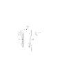
- the three-dimensional gather BS that fits around the legs is formed on both sides of the interior body 10.
- the three-dimensional gather BS includes a fixed portion fixed to a side portion on the back surface of the interior body, and a side portion on the surface of the interior body from the fixed portion to the side of the interior body.
- the body part that extends to the front, the front and rear ends of the body part in a lying state, and the lying part that is fixed to the side of the surface of the interior body, and the freedom part that is formed with this lying part being unfixed
- the part is formed of a gathered nonwoven fabric 15 that is turned into a double sheet by folding.
- an elongated gather elastic member 16 is disposed at the free end of the free portion.
- the gather elastic member 16 is for forming a three-dimensional gather BS by raising a free part by elastic expansion and contraction force as shown by a two-dot chain line in FIG. 19 in the product state.
- the liquid-impermeable back sheet 12 is folded back on the both sides in the width direction of the absorber 13 together with the liquid-permeable surface sheet 11.
- the liquid-impermeable back side sheet 12 it is desirable to use an opaque sheet so that brown such as defecation and urine does not appear.
- a plastic film and a pigment and filler such as calcium carbonate, titanium oxide, zinc oxide, white carbon, clay, talc and barium sulfate are preferably used.
- the gather elastic member 16 materials such as styrene rubber, olefin rubber, urethane rubber, ester rubber, polyurethane, polyethylene, polystyrene, styrene butadiene, silicon, polyester and the like that are usually used can be used. In order to make it difficult to see from the outside, it is preferable that the thickness is 925 dtex or less, the tension is 150 to 350%, and the interval is 7.0 mm or less.
- the gathered elastic member 16 may be a tape-like member having a certain width in addition to the thread-like shape shown in the figure.
- the material fiber constituting the gathered nonwoven fabric 15 is made of synthetic fibers such as polyethylene or polypropylene, synthetic fibers such as polyester or amide, recycled fibers such as rayon or cupra, and cotton.
- Non-woven fabric obtained by an appropriate processing method such as a spunbond method, a thermal bond method, a melt blown method, a needle punch method, etc. can be used. It is preferable to use a nonwoven fabric that suppresses the basis weight and has excellent air permeability.
- the gathered nonwoven fabric 15 in order to prevent the transmission of urine and the like, to prevent fogging, and to enhance the touch to the skin (dry feeling), silicon-based, paraffin metal-based, alkylchromic croid-based water repellent, etc. It is desirable to use a water-repellent non-woven fabric coated with.
- the exterior body 20 is provided with an elastic film 30 and an elongated elastic member 24 along the width direction between the first sheet layer 21 and the second sheet layer 22, Elasticity in the width direction is given.
- the planar shape of the exterior body 20 has a pseudo hourglass shape as a whole due to concave leg-around lines 29 formed to form leg openings on both sides of the middle.
- the exterior body 20 may be divided into two parts in the front-rear direction so that both are separated in the front-rear direction at the crotch part.
- the waist part is elastic to the waist part 23 in the waist area defined as the longitudinal range of the side seal part 26 where the front body Fr and the back body Ba are joined.
- a member 24 is provided.
- the waist elastic member 24 in the illustrated form is an elongated elastic member such as a plurality of rubber bands arranged at intervals in the vertical direction, and gives a stretching force so as to tighten around the body torso.
- the waist elastic members 24 are not arranged substantially as a single bundle with a close spacing, but with a spacing of about 3 to 8 mm so as to form a predetermined stretch zone, preferably three or more, preferably Five or more are arranged.
- the elongation rate at the time of fixing the waist elastic member 24 can be determined as appropriate, but can be about 230 to 320% for a normal adult.
- the waist elastic member 24 one or a plurality of belt-like elastic members can be used.
- the rubber elastic member 24 is made of rubber thread. However, for example, a tape-like elastic member may be used. Alternatively, an elastic film described later may be extended to the waist 23. .
- the waist elastic member 24 in the illustrated form is sandwiched between folded portions 20C formed by folding the constituent material of the second sheet layer 22 to the inner surface side at the waist opening edge. You may pinch
- the constituent material of the 1st sheet layer 21 and the 2nd sheet layer 22 can be used without a limitation especially if it is a sheet form, it is preferable to use a nonwoven fabric from a viewpoint of air permeability and a softness
- the nonwoven fabric is not particularly limited as to what the raw fiber is.
- synthetic fibers such as olefins such as polyethylene and polypropylene, polyesters and polyamides, recycled fibers such as rayon and cupra, natural fibers such as cotton, and mixed fibers and composite fibers using two or more of them. Etc. can be illustrated.
- the nonwoven fabric may be manufactured by any processing.
- the processing method examples include known methods such as a spunlace method, a spunbond method, a thermal bond method, a melt blown method, a needle punch method, an air through method, and a point bond method.
- the basis weight is preferably about 10 to 25 g / m 2 .
- the first sheet layer 21 and the second sheet layer 22 may be a pair of layers in which a part or all of the first sheet layer 21 is folded and faced.
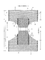
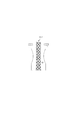
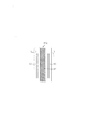
- the waist area T of the front body Fr, the waist area T of the back body Ba, and the intermediate area L between them in the exterior body 20 are made of the stretchable sheet described above.
- a laminated stretchable structure 20X is formed. That is, in the stretchable structure 20X of the exterior body 20, in the width direction intermediate portion including the portion overlapping the absorber 13 (a part or all of the overlapping portion may be included, and it is desirable to include substantially the entire interior body fixing portion 10B).
- a non-stretchable region 70 is provided, and portions up to the side seal portion 26 on both sides in the width direction are the stretchable regions 80. Then, as shown in FIG.
- the elastic film 30 is laminated between the first sheet layer 21 and the second sheet layer 22 over the entire stretchable region 80 and non-stretchable region 70, and the elastic film.
- the first sheet layer 21 and the second sheet layer 22 are formed by a large number of joints 40 arranged at intervals in the expansion / contraction direction and the direction orthogonal thereto (elasticity). Bonded through a through-hole 31 formed in the film 30.
- such a laminated stretchable structure 20X basically, the higher the area ratio of the joint portion 40, the smaller the portion where the first sheet layer 21 and the second sheet layer 22 are contracted by the elastic film 30, so that the elastic limit elongation is increased.
- the area ratio of the opening of the through hole 31 in the elastic film 30 also increases, and the proportion of the stretchable direction continuous portion of the elastic film 30 occupying in the direction orthogonal to the stretchable direction decreases. There is a tendency that the elastic film 30 is easily torn as the contraction force generated is reduced.
- the area ratio of the joint portion 40 is higher than that of the stretchable region 80, so that the elastic limit elongation in the stretch direction is 130% or less (preferably 120% or less, more preferably
- the elastic limit elongation in the stretchable direction is 200% or more (preferably 265 to 295%).
- “elastic limit elongation” means the elongation at the elastic limit (in other words, the state where the first sheet layer and the second sheet layer are completely expanded), and the natural length of the length at the elastic limit is 100. The percentage is expressed as%.
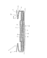
- the first sheet layer 21 and the second sheet layer 22 between the joints swell in a direction away from each other and intersect the stretchable direction.
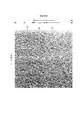
- a shrinking ridge 25 that bulges in the direction is formed. Even in a mounted state that extends to some extent in the width direction, the degree of bulge of the shrinking ridge 25 is small but remains. Note that the state of the shrinkage wrinkle 25 in the mounted state and the natural length state also appears in the sample photographs in FIGS.
- non-stretchable region 70 As can be seen from the sample photographs of FIGS. 25 to 27, a streaky portion or extremely small wrinkles are formed between the joint portions 40, but the area ratio of the joint portion 40 is extremely high. Therefore, the elasticity is substantially killed.
- FIG.16 and FIG.22 (a) shows, the edge part by the side of the non-expanding-contraction area
- region 80 is joined part 40 rather than the main expansion-contraction part 81 except the said edge part.
- the buffer stretchable part 82 has a low area ratio.
- the buffer expansion / contraction part 82 may not be provided.
- the shapes of the individual joints 40 and the through holes 31 in the natural length state are arbitrary shapes such as polygons (including linear and rounded ones) such as true circles, ellipses, and rectangles, stars, and clouds. It can be.
- the size of each joint 40 may be determined as appropriate, but if it is too large, the effect of the hardness of the joint 40 on the feel will increase, and if it is too small, the joint area will be small and the materials will not be sufficiently bonded together. Therefore, in general, the area of each joint 40 is preferably about 0.14 to 3.5 mm 2 .
- the opening area of each through-hole 31 may be equal to or greater than the joint because the joint is formed through the through-hole 31, but is preferably about 1 to 1.5 times the area of the joint.
- each joint 40 in each region are as follows in a normal case.
- Non-stretchable region 70 Area of the joint 40: 0.14 to 3.5 mm 2 (particularly 0.25 to 1.0 mm 2 ) Area ratio of the joint 40: 16 to 45% (especially 25 to 45%)
- Mainn stretchable part 81 Area of the joint 40: 0.14 to 3.5 mm 2 (particularly 0.14 to 1.0 mm 2 ) Area ratio of the joint 40: 1.8 to 19.1% (particularly 1.8 to 10.6%)
- Buffer expansion / contraction part 82 Area of the joint 40: 0.14 to 3.5 mm 2 (particularly 0.25 to 1.0 mm 2 ) Area ratio of the joint 40: 8 to 22.5% (especially 12.5 to 22.5%)
- the area of the joint portion 40 can be the same in two or more of the non-stretchable region 70, the main stretchable portion 81 and the buffer stretchable portion 82, and can be different in all locations.
- the number of the joint portions 40 per unit area may be the same at two or more of the non-stretchable region 70, the main stretchable portion 81, and the buffer stretchable portion 82, and may be different at all locations.
- the plane arrangement of the joints 40 and the through holes 31 can be determined as appropriate, but a plane arrangement that repeats regularly is preferable, and an oblique lattice shape as shown in FIG. 28 (a) or as shown in FIG. 28 (b).
- Hexagonal lattice shape (these are also called staggered shapes), a square lattice shape as shown in FIG. 28 (c), a rectangular lattice shape as shown in FIG. 28 (d), and a parallel shape as shown in FIG. 28 (e).
- Body lattice in the form shown in the figure, two groups are provided so that a large number of groups of parallel diagonal rows intersect each other), etc.
- the group of joints 40 (in which these are inclined at an angle of less than 90 degrees with respect to the expansion / contraction direction)
- group of joints 40 (group unit arrangement may be regular or irregular, and may be a pattern, a character shape, etc.) shall be regularly repeated. You can also.
- the arrangement form of the joint portion 40 and the through hole 31 may be the same or different in the main stretchable portion 81, the buffer stretchable portion 82, and the non-stretchable region 70.
- a non-stretchable region 70 in which the joint portion 40 is arranged in a display 71 shape or the like can be provided.
- a buffer expansion-contraction part can be provided in the expansion / contraction area
- the display 71 may be a display known in the field of absorbent articles, for example, a decorative pattern (including a one-point picture or character), a function display such as a method of use or assistance, and a size, or a manufacturer or It can be a mark display of product name, characteristic function, etc.
- a flower pattern display 71 which is a plant pattern is added, but it is needless to say that various patterns such as an abstract pattern, an animal pattern, and a natural phenomenon pattern can be used.
- the elastic film 30 is not particularly limited, and can be used without particular limitation as long as it is a resin film having its own elasticity.
- a styrene-based elastomer, an olefin-based elastomer, a polyester-based elastomer, a polyamide-based elastomer, and a polyurethane-based film can be used.
- a product obtained by processing one or two or more blends of thermoplastic elastomers such as elastomers into a film by extrusion molding such as a T-die method or an inflation method can be used.
- the elastic film 30 the thing in which many holes and slits were formed for ventilation other than a non-porous thing can also be used.
- the tensile strength in the stretching direction is 8 to 25 N / 35 mm
- the tensile strength in the direction perpendicular to the stretching direction is 5 to 20 N / 35 mm
- the tensile elongation in the stretching direction is 450 to 1050%
- the direction perpendicular to the stretching direction is preferable.
- the tensile strength and tensile elongation were determined according to JIS K7127 except that a tensile tester (for example, AOUTGRAPHAGS-G100N manufactured by SHIMADZU) was used and the test piece was a rectangular shape having a width of 35 mm and a length of 80 mm.
- a tensile tester for example, AOUTGRAPHAGS-G100N manufactured by SHIMADZU
- the thickness of the elastic film 30 is not particularly limited, but is preferably about 20 to 40 ⁇ m.
- the basis weight of the elastic film 30 is not particularly limited, but is preferably about 30 to 45 g / m 2 , particularly preferably about 30 to 35 g / m 2 .
- the melting point of each constituent member of the stretchable sheet according to the present invention can be appropriately selected.
- the elastic film has a melting point of 95 to 125 ° C., more preferably 100 to 120 ° C.
- the melting point of the sheet layer is more than 125 ° C. to 160 ° C., more preferably 130 to 160 ° C.
- the melting point of the second sheet layer is more than 125 ° C. to 160 ° C., more preferably 130 to 160 ° C.
- the ultrasonic welding temperature can be changed by selecting ultrasonic energy from the horn.
- the ultrasonic energy from this horn cannot be directly converted into temperature, but when measured with a non-contact type thermometer, the temperature on the horn side is 40 ° C.
- an optimal nonwoven fabric is a spunbond nonwoven fabric.
- the illustrated example is an example in which the laminated stretchable structure 20X is applied to a stretchable structure other than the waist portion 23 of the exterior body 20.
- the laminated stretchable structure 20X may be applied including the waist portion 23, or the waist region T and the back body Ba of the front body Fr.
- Appropriate changes are possible, such as a configuration in which the laminated stretchable structure 20 ⁇ / b> X is not provided in the intermediate region L with respect to the waistline region T.
- the stretchable structure 20X described above is not limited to pants-type disposable diapers, but also to other stretchable parts such as three-dimensional gathers, flat gathers, etc. that are widely used around the waist of a tape-type disposable diaper, fastening tape, and absorbent articles in general.
- this embodiment has a non-stretchable region, it is also possible to use a configuration in which the entire laminated stretchable structure is a stretchable region and does not have a non-stretchable region.
- the expansion / contraction direction is the width direction, but it is also possible to use the front-rear direction or both the width direction and the front-rear direction.
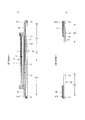
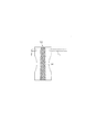
- the front presser sheet 50 extends over the entire width direction from the inner surface of the folded portion 20C of the waist side end portion to the position overlapping the front end portion of the interior body 10 in the inner surface of the front body Fr.
- the rear pressing sheet 60 extends across the entire width direction from the inner surface of the folded portion 20C at the waist side end portion to the position overlapping the rear end portion of the interior body 10 in the rear body Ba inner surface.
- the folded portion 20C formed by folding the exterior body 20 on the inner surface of the diaper can be extended to a portion overlapping the interior body 10 to form a portion equivalent to the above-described pressing sheets 50 and 60.
- a spunbond nonwoven fabric having a basis weight of 17 g / m 2 made of PE / PP composite fiber (core: polypropylene (melting point: 165 ° C.), sheath: polyethylene (melting point: 130 ° C.)), An elastic film having a basis weight of 35 g / m 2 , a thickness of 35 ⁇ m, and a melting point of 110 to 120 ° C. was used.
- the elastic film is sandwiched between the first sheet layer and the second sheet layer so that the MD direction is aligned in a natural length state (regardless of whether it is a natural length or a stretched state in relative comparison of peel strength),
- a sonic seal device (“Haru SUH-30" manufactured by Suzuki)
- a rectangular joint 40 having a long side along the MD direction (short side 1.0 mm, long side) 1.5 mm) is formed in a rectangular lattice shape with a 1 mm interval in the CD direction perpendicular to the MD direction and a 17 mm interval in the MD direction, and a sample with an elastic film having a CD direction length of 100y80 mm and a MD direction length of 100x is 50 mm.
- the ultrasonic seal was pressed for about 3 seconds and was bonded so that the same person had the same pressure.
- the MD direction of the nonwoven fabric is the direction of fiber orientation of the nonwoven fabric (the direction along which the nonwoven fabric fibers are aligned).
- a measurement method according to the fiber orientation test method based on zero distance tensile strength of the TAPPI standard method T481 It can be discriminated by a simple measuring method for determining the fiber orientation direction from the tensile strength ratio in the direction and the width direction.
- a sample without an elastic film was produced in the same manner as in the example except that the elastic film was removed and a two-layer structure was used (comparative example).
- Pants type disposable diapers shown in FIGS. 15 to 21 Examples having an exterior body using an elastic film
- three types of commercially available pants type disposable diapers using thread rubber for the exterior body Comparative Examples 1 to 3
- Two types of underwear were prepared, and the fitting property in the wearing state was confirmed by measuring the contact pressure of the exterior body.
- the specifications of each diaper are as follows.
- First and second sheet layers PE / PP composite fiber (core: polypropylene (melting point 165 ° C.), sheath: polyethylene (melting point 130 ° C.)) as a raw material, a spunbonded nonwoven fabric having a basis weight of 17 g / m 2 .
- Elastic film basis weight 35 g / m 2 , thickness: 35 ⁇ m, melting point: 110 to 120 ° C.
- Non-stretchable area 70 Area of joint 40: 0.19 mm 2 Area ratio of the joint 40: 7.0% Elastic elongation limit: 110%
- Comparative Example 1 a rubber thread having a thickness of 310 dtex is attached in the front-rear direction at an interval of 6 mm in the waistline region, and the elastic limit elongation in the width direction of the stretchable region having the rubber thread is 220%. Is.
- Comparative Example 2 In Comparative Example 2, a thread rubber having a thickness of 620 dtex is attached to the waistline region with an interval of 9 mm in the front-rear direction, and the elastic limit elongation in the width direction of the stretchable region having the rubber thread is 200%. Is.
- Comparative Example 3 (Comparative Example 3)
- thread rubber (not measurable because the thickness is thin and weak) is attached to the waist area with a space of 1 mm in the front-rear direction, and the elastic limit in the width direction of the stretchable area having this rubber thread The elongation is 160%.
- a cylindrical body (having a height higher than the region around the trunk to be tested) is prepared using a foamed PVC sheet having a thickness of 2 mm. (2) The cylindrical body is inserted and installed in the waist portion from the waist opening so that the circumferential direction of the cylindrical body and the waist direction coincide with each other. (3) Using a contact pressure measuring instrument (AMI3037-2) manufactured by AIM Techno Co., Ltd. and an air pack (pressure sensor) with a diameter of 20 mm, the air pack is placed between the region around the body to be measured and the outer peripheral surface of the cylindrical body. The sandwich was measured and the pressure (kPa) was measured.
- AMI3037-2 manufactured by AIM Techno Co., Ltd.
- an air pack pressure sensor
- the measurement site of the pants-type disposable diaper is the region around the side edge of the interior body and below the waist portion in the region around the waist of the front body, and in the embodiment, the air pack is positioned at the main stretchable portion 81.
- the air pack is positioned at the main stretchable portion 81.
- three or more rubber threads overlap the air pack.
- the measurement site of the underwear was the same as the measurement position of the pants-type disposable diaper. (4) Assuming an adult's waist, the circumference of the cylinder was changed from 60 cm to 95 cm in increments of 5 cm, and the above measurements (1) to (3) were repeated.
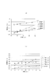
- FIG. 51 (a) shows the measurement results of the contact pressure in Examples and Comparative Examples 1 to 3.
- the measurement results of contact pressure of underwear 1 (M), underwear 1 (L), underwear 2 (M), underwear 2 (L), and Comparative Example 1 are shown in FIG.
- the pants type disposable diapers of Comparative Examples 1 to 3 are different from the underwear, whereas the pants type disposable diapers of the examples are different. The fit was found to be close to that of underwear.
- the contact pressure in the entire range of the circumferential length of 60 to 95 cm is preferably 0.3 to 1.2 kPa, and particularly preferably 0.4 to 0.8 kPa. It was also found out.
- the contact pressure can be adjusted by changing the type of elastic film 30, elastic limit elongation, joint area ratio, and the like.
- the stretchable elastic sheet can be applied to a tape-type disposable diaper, and can be used particularly as a means for fitting around a leg of a wearer.
- the tape-type disposable diaper TD1 having tapes on both sides on the back side extends in the front-rear direction around the crotch area on both sides of the product, and expands and contracts in the front-rear direction.
- the elastic part 83 to be formed can be formed. That is, the stretchable sheet 83 is manufactured, and the stretchable portion 83 is formed by partially making the joint area ratio smaller than the joint area ratio of other portions.
- the expansion / contraction stress in the front-rear direction is different between the width directions by making the joint area ratio different between the joint area ratio of the expansion / contraction part 83 along the front-rear direction and the width direction both side areas.
- the configuration is different.
- the expansion-contraction part 83 expands-contracts in the front-back direction, since the whole expansion-contraction part 83 contact
- the area ratio of the joint portion can be increased so that it does not substantially stretch.
- a certain degree of stretchability can be exhibited without excessively increasing the joint area ratio.
- the stretchable part 83 can be stretched in the front-rear direction and can be stretched in the width direction to improve the fit.
- FIGS. 31 to 34 examples of FIGS. 31 to 34 can be given.
- an absorbent body 3 is interposed between the inner surface of the laminated back sheet 1 forming the back surface and the liquid-permeable top sheet 2.
- the liquid-impermeable laminated back sheet 1 extends outward from the periphery of the absorbent body 3 and blocks movement of excrement absorbed by the absorbent body 3 to the back surface side.
- a sheet having moisture permeability can be used without impairing water shielding from the viewpoint of preventing stuffiness.
- the entire back surface of the laminated back sheet 1 is covered with a nonwoven fabric layer (the first sheet layer 21 or the second sheet layer 22 described above), and both sheets 1 and 2 are covered.
- the outer peripheral edge of the diaper extends to the outer peripheral edge of the diaper.
- a spunbonded nonwoven fabric is suitable as the nonwoven fabric layer.
- top sheet As the top sheet 2, a perforated or non-porous nonwoven fabric or a perforated plastic sheet is used.
- material fiber constituting the nonwoven fabric synthetic fibers such as polyethylene or polypropylene, synthetic fibers such as polyester and amide, recycled fibers such as rayon and cupra, and natural fibers such as cotton can be used.
- processing method of a nonwoven fabric well-known methods, such as the spunlace method, the spun bond method, the SMS method, the thermal bond method, the melt blown method, the needle punch method, the air through method, the point bond method, can be used.
- the fiber basis weight of the nonwoven fabric used for the liquid-permeable top sheet 2 is preferably 15 to 30 g / m 2 , and the thickness is preferably 0.05 to 1 mm.
- the top sheet 2 extends outward from the periphery of the absorber 3, and a portion extending outward from the side edge of the absorber 3 is fixed to the laminated back sheet 1 with, for example, a hot melt adhesive.
- the dot pattern in a figure represents the adhering part.
- the leg gathering three-dimensional gather sheets 4 and 4 can use various non-woven fabrics (preferably spunbond non-woven fabrics), plastic films similar to those used for back sheets, or these stretchable sheets. From the viewpoint of the touch, a nonwoven fabric subjected to a water repellent treatment is preferable.
- the projecting portion on the center side in the width direction of the three-dimensional gather sheet around the legs is fixed to the inner surface of the article (in the illustrated form, the top sheet 2 surface) by means such as hot melt adhesive at the both ends in the front-rear direction, and is used as a lying portion.
- the intermediate part in the front-rear direction between them is a non-fixed free part, and the end part of this free part (end part on the center side in the width direction in the unfolded state) is elongated such as rubber thread.
- the elastic elastic member 4G is fixed with a hot-melt adhesive or the like in a state of extending along the front-rear direction.
- a plurality of the elongated elastic elastic members 4G are provided with a predetermined interval, but one may be used. As shown in FIG.
- this free portion is formed by a three-dimensional gathering around the legs that stands on the use surface of the diaper (the surface of the top sheet 2 in the illustrated embodiment). Constitute.
- Fastening tapes T that protrude from the side edges are attached to the side flaps of the back part B, and a front target tape 6 is attached to the waist part surface of the abdomen part F along the width direction.
- the fastening tape T on both sides is turned from each side of the waist to the abdomen outer surface and fastened to the front target tape 6 via the hook material 5.
- the front target tape 6 can be omitted.
- the fastening tape T is directly hooked and fixed to the nonwoven fabric on the outer surface of the diaper.
- Reference numeral 7 denotes a dividing perforation.
- the constituent material of the first sheet layer 21 and the second sheet layer 22 can be used without particular limitation as long as it is a sheet, but it is preferable to use a nonwoven fabric from the viewpoint of air permeability and flexibility.
- the nonwoven fabric is not particularly limited as to what the raw fiber is.
- synthetic fibers such as olefins such as polyethylene and polypropylene, polyesters and polyamides, recycled fibers such as rayon and cupra, natural fibers such as cotton, and mixed fibers and composite fibers using two or more of them. Etc. can be illustrated.
- the nonwoven fabric may be manufactured by any processing.
- the processing method examples include known methods such as a spunlace method, a spunbond method, a thermal bond method, a melt blown method, a needle punch method, an air through method, and a point bond method.
- the basis weight is preferably about 10 to 25 g / m 2 .
- each joint part 40 and the through-hole 31 is arbitrary, such as a perfect circle, an ellipse, polygons, such as a rectangle (including a linear or rounded thing), a star shape, a cloud shape, etc. It can be made into the shape.
- the size of each joint 40 may be determined as appropriate, but if it is too large, the effect of the hardness of the joint 40 on the feel will increase, and if it is too small, the joint area will be small and the materials will not be sufficiently bonded together. Therefore, in general, the area of each joint 40 is preferably about 0.14 to 3.5 mm 2 .
- the opening area of each through-hole 31 may be equal to or greater than the joint because the joint is formed through the through-hole 31, but is preferably about 1 to 1.5 times the area of the joint.
- tape-type disposable diaper a type in which the front body is wrapped with one long tape Ta as shown in FIG.
- tape-type disposable diaper As the tape-type disposable diaper, as shown in FIG. 36, a so-called “straight type” having straight edges on both sides may be used.
- a pad-type disposable diaper PD that does not include a tape and is arranged as it is inside the underwear or inside the tape-type disposable diaper may be used.
- the stretchable part may be formed along the leg-cut part.
- the crotch region may be constricted toward the center, and may have an expansion / contraction portion 83A that extends in the front-rear direction along the constriction and expands and contracts in the front-rear direction.
- the formation of the expansion / contraction portion of the present invention is easy to appropriately select the pattern of the projection portion of the anvil roll. Easy. If the pattern part of the stretchable part formed wider is cut around the leg, the stretchable part 83A can be formed up to the edge around the leg, without forming a flap necessary for manufacturing when using conventional rubber thread. Good.
- the expansion and contraction stress can be made different between the front and rear in the leg elastic part 83B. That is, it is preferable to increase the stretching stress at the middle part in the front-rear direction of the leg-surrounding stretchable part 83B and to reduce the stretching stress at the front and back. With this configuration, it is possible to prevent the disposable diaper from being easily rounded before and after.
- the stretching stress can be varied in the width direction in the leg-surrounding stretchable part 83C.
- This brings about an advantage that fitting according to the wearer's body shape is possible. That is, when the expansion / contraction stress in the width direction outward of the leg-hole expansion / contraction part 83C is increased and the expansion / contraction stress in the width direction is decreased, the outer shape of the diaper becomes an arc shape along the body shape. Rise. On the other hand, if the expansion / contraction stress in the width direction outward of the leg elastic part 83C is decreased and the expansion / contraction stress in the width direction is increased, the tightening force in the crotch part is increased for a wearer with a thick thigh. Increases fit.
- an absorbent article for example, a tape-type disposable diaper, which can be stretched at least in the front-rear direction and includes an exterior sheet having a stretchable portion at least in the center region in the width direction.
- seat which has the expansion-contraction part 84 in the width direction center area
- the expansion / contraction ratio differs between the front / rear part 84A and the intermediate part 84B, that is, the front / rear part 84A is difficult to expand (for example, the expansion ratio is The intermediate portion 84B can be easily stretched. In this case, the wearer or the caregiver has good wearability because the front and rear regions do not extend excessively and there is resistance to elongation.
- the stretchable portions 84A and the intermediate portions 84B have different stretch rates, and the widthwise lengths of the stretchable front and back portions 84A are easily stretched. It can be larger than the width of 84B.
- the expansion / contraction rate can be made different between the width direction outer portion 84a and the center portion 84b among the expansion / contraction portions 84 in the width direction central region.
- the area ratio of the joint portion is such that the central portion 84b> the outer portion 84a> both side portions, a cross-sectional bay shape along the wearer's surface is obtained, and the fitting property is high.
- the disposable diaper TD2 may be of a so-called “fundoshi” type. Also, as shown in FIG. 47, a so-called “straight type” may be used.
- a tape-type disposable diaper TD3 which includes an exterior sheet and an absorbent body that can be stretched at least in the front-rear direction and has an stretchable portion at least in the center region in the width direction.
- the central region in the width direction indicated by reference numeral 85 in FIG. 48 (a) is a region extending before and after a portion to which body pressure is applied at the time of wearer. Further, the absorber 13 is provided in the central region in the width direction.
- the front and back of the diaper mainly floats (separates) from the body surface, or may shift in the front-rear direction, but there is no such problem in the form in which the central region in the width direction expands and contracts, Leakage can also be prevented.
- the wrinkle along the width direction orthogonal to the front / rear direction is generated on the outer surface of the diaper due to the contraction of the expansion / contraction part 85, so that the wearer gets up from the supine state. Sometimes it also has an anti-slip effect on the buttocks.
- the absorbent body 13 when the absorbent body 13 is provided in the central region in the width direction, there is a risk of leakage if the absorbent body 13 approaches, so that the outer sheet that defines the outer shape of the product is small in the area where the absorbent body 13 is disposed. Is desirable. Therefore, as shown in FIG. 48 (b), in the stretchable portion 85 in the central region in the width direction, the stretch rate is different between the front and rear portions 85A and the intermediate portion 85B, that is, the intermediate portion 85B is difficult to stretch (for example, The elongation ratio is 200% or less), and the front and rear portions 85A can be easily elongated.
- the lateral width of the front and rear portions 85A may be short as shown in the figure or the same as the lateral width of the intermediate portion 85B. Furthermore, as shown in FIG. 49, the lateral width of the front and rear portions 85A may extend over the entire width direction.
- the expansion / contraction ratio can be made different between the width direction outer portion 85a and the center portion 85b in the expansion / contraction portion 85 in the central region in the width direction.
- the area ratio of the joint portion is such that the central portion 85b> the outer portion 85a> the both side portions, a cross-sectional bay shape along the wearer's surface is obtained, and the fitting property is high.
- the absorbent body in the tape-type disposable diaper shown in FIGS. 48 to 50 is a part that absorbs and retains body fluid, and refers to, for example, cotton-like pulp or a polymer-absorbing polymer, and has a thickness of 2 mm or more. Means part.
- Elongation rate means a value when the natural length is 100%.
- Weight is measured as follows. After the sample or test piece has been pre-dried, it is left in a test room or apparatus in a standard state (test location is temperature 20 ⁇ 5 ° C., relative humidity 65% or less) to obtain a constant weight. Pre-drying refers to making a sample or test piece constant in an environment where the relative humidity is 10 to 25% and the temperature does not exceed 50 ° C. In addition, it is not necessary to perform preliminary drying about the fiber whose official moisture content is 0.0%.
- a sample with a size of 200 mm ⁇ 250 mm ( ⁇ 2 mm) is cut out from the test piece in a constant weight state using a rice-basis plate (200 mm ⁇ 250 mm, ⁇ 2 mm). Measure the weight of the sample, multiply it by 20, calculate the weight per square meter, and use it as the basis weight. “Thickness” is automatically measured using an automatic thickness measuring instrument (KES-G5 handy compression measurement program) under the conditions of load: 10 gf / cm 2 and pressure area: 2 cm 2 . ⁇ If there is no description about the environmental conditions in the test and measurement, the test and measurement shall be performed in a test room or equipment in a standard state (test location is temperature 20 ⁇ 5 ° C, relative humidity 65% or less). .
- the present invention can be used for a wide variety of absorbent articles having an elastic structure, such as a pants-type disposable diaper as in the above example, various disposable diapers such as a tape type and a pad type, and sanitary napkins.
- the stretchable sheet of the present invention can also be applied to auxiliary materials such as tape-type disposable diaper tape.
Landscapes
- Engineering & Computer Science (AREA)
- Mechanical Engineering (AREA)
- Health & Medical Sciences (AREA)
- Biomedical Technology (AREA)
- Epidemiology (AREA)
- Textile Engineering (AREA)
- Heart & Thoracic Surgery (AREA)
- Vascular Medicine (AREA)
- Life Sciences & Earth Sciences (AREA)
- Animal Behavior & Ethology (AREA)
- General Health & Medical Sciences (AREA)
- Public Health (AREA)
- Veterinary Medicine (AREA)
- Toxicology (AREA)
- Absorbent Articles And Supports Therefor (AREA)
Abstract
Provided is an absorbent article comprising an elastic sheet having elastic sections wherein the stretching stress differs according to the location on the elastic sheet. The absorbent article is provided with an elastic sheet, wherein the elastic sheet has an elastic film (30), which is capable of stretching in at least the longitudinal direction, layered between a first sheet layer (21) that does not stretch and a second sheet layer (22), and the first sheet layer (21) and the second sheet layer (22) are joined directly or with the elastic film (30) therebetween via a number of joints (40) which are spaced at intervals; the elastic sheet contracts due to the contractile force of the elastic film (30), and can be stretched by applying an external force in the longitudinal direction; and the stretching stress differs in regions of the elastic sheet as a result of differences, in one direction, in joint area ratios which represent the total area occupied by the joints (40) contained in a unit area.
Description
本発明は、第1シート層と第2シート層とが弾性フィルムを挟んでなる伸縮シートを備えた吸収性物品、及びその製造方法に関する。
The present invention relates to an absorbent article provided with an elastic sheet in which a first sheet layer and a second sheet layer sandwich an elastic film, and a method for manufacturing the same.
吸収性物品、例えば使い捨ておむつにおいては、身体表面へのフィット性を向上するために、脚周りや胴周り等の適所に伸縮性を付与することが一般的である。伸縮性を付与するための手法としては、従来、糸ゴム等の細長状弾性伸縮部材を長手方向に伸長した状態で固定する手法が広く採用されているが、ある程度の幅で伸縮性を付与したい場合には、糸ゴムを幅に間隔を置いて並べて配置した状態で固定する態様が採用されている。
In an absorbent article, for example, a disposable diaper, in order to improve fit to the body surface, it is common to impart stretchability to appropriate places such as around the legs and around the trunk. As a method for imparting stretchability, conventionally, a method of fixing an elongated elastic stretchable member such as rubber thread in a stretched state in the longitudinal direction has been widely adopted, but it is desired to impart stretchability to a certain width. In such a case, a mode is adopted in which the rubber thread is fixed in a state of being arranged side by side with an interval in width.
他方、並行に配置した複数本の糸ゴムに替えて、面状に押圧し伸縮性を付与するとともに、肌触りを考慮したものとして、不織布/エラストマーフィルム/不織布を使用するものも提案されている。(例えば特許文献1参照)。
On the other hand, in place of a plurality of thread rubbers arranged in parallel, a non-woven fabric / elastomer film / non-woven fabric is also used as a material that gives a stretch property by pressing in a planar shape and considering the touch. (For example, refer to Patent Document 1).
しかし、特許文献1のものは、第1外層と第2外層の間に、これより融点が高い又は融点を有しない連続したMD方向(マシン方向)に伸縮する弾性フィルムを供給し、所定の位置で第1外層と第2外層とを直接に溶着により結合させ、その後、CD方向(マシン方向と直交する方向)に引っ張る力を作用させることによって、結合部位に第1外層、弾性フィルム及び第2外層全体に貫通する貫通孔を形成するものである。
However, the thing of patent document 1 supplies the elastic film which expands-contracts in the continuous MD direction (machine direction) where melting | fusing point is higher than this, or does not have melting | fusing point between 1st outer layer and 2nd outer layer, and predetermined position Then, the first outer layer and the second outer layer are directly bonded by welding, and then a pulling force is applied in the CD direction (a direction orthogonal to the machine direction), whereby the first outer layer, the elastic film, and the second are applied to the bonding site. A through-hole penetrating the entire outer layer is formed.
特許文献1による伸縮シートは、連続製造を意図しているので、結合部を形成する熱接着ローラにおける隆起部のパターンは幅方向及び周方向に一様であり、したがって、製造された伸縮シートは、幅方向位置が異なっていても、伸縮応力は均一である。
したがって、この伸縮シートの用途が広いとは言い難い。 Since the stretchable sheet according toPatent Document 1 is intended for continuous production, the pattern of the raised portions in the heat bonding roller forming the joint is uniform in the width direction and the circumferential direction. Even if the position in the width direction is different, the stretching stress is uniform.
Therefore, it is difficult to say that this stretchable sheet is widely used.
したがって、この伸縮シートの用途が広いとは言い難い。 Since the stretchable sheet according to
Therefore, it is difficult to say that this stretchable sheet is widely used.
他方、使い捨ておむつの脚周りに複数本の糸ゴムを並べて前後方向に沿って配置し、脚周りからの横漏れを防止する構造は周知である。
さらに、脚周りの括れに沿って曲線状の伸縮性脚周りシートを設けることも知られている(特許文献2)。 On the other hand, a structure in which a plurality of thread rubbers are arranged around the legs of the disposable diaper and arranged along the front-rear direction to prevent side leakage from the legs is well known.
Furthermore, it is also known to provide a curvilinear elastic leg leg sheet along the leg circumference (Patent Document 2).
しかし、この種の脚周りの伸縮手段は、シートに別の伸縮性部材を設けるので、部材点数が多くなる要因であり、また製造の際に位置決め制御が必要となり安定生産を阻害するなどの問題がある。
However, this type of expansion / contraction means around the legs is a factor that increases the number of members because a separate elastic member is provided on the seat, and also requires problems such as positioning control during manufacturing and hinders stable production. There is.
そこで本発明の主たる課題は、伸縮シートの領域内において位置によって伸縮応力が相違する伸縮部を有する伸縮シートを備える吸収性物品を提供することにある。
Therefore, a main problem of the present invention is to provide an absorbent article including an elastic sheet having an elastic part having different elastic stress depending on the position in the region of the elastic sheet.
上記課題を解決した本発明は次のとおりである。
The present invention that has solved the above problems is as follows.
(基本形態)
本発明の吸収性物品は、少なくとも一方向に伸縮可能な伸縮部を有する伸縮シートを備える。
前記伸縮シートにおいて、伸縮性を有しない例えば不織布からなる第1シート層と、伸縮性を有しない例えば不織布からなる第2シート層との間に、前記一方向に伸縮可能な弾性フィルムが積層されており、かつ、前記第1シート層及び前記第2シート層が、直接又は弾性フィルムを介して、間隔を開けた多数の接合部で接合されている。
前記伸縮部は、前記弾性フィルムの収縮力により収縮し、前記一方向に外力を加えると伸長可能である。
前記伸縮シートにおいて、単位面積内に含まれる前記接合部の総和面積が占める接合部面積率が前記一方向に異なっていることにより、伸縮応力が相違している。
この伸縮応力の相違の方向は、伸縮部の配置形態によって適宜選択でき、例えば使い捨ておむつの腰周り又はウエスト周りに適用する場合には、その方向に伸縮可能なものとして適用し、すなわち前記一方向を腰周り又はウエスト周り方向として適用し、その一方向の伸縮応力を相違させる態様がある。
他方で、例えば使い捨ておむつの脚周り又は中央領域の前後方向に伸縮可能にする場合には、前記一方向を前後方向として適用し、その一方向と直交する方向(直交方向)の伸縮応力を相違させる態様がある。 (Basic form)
The absorptive article of the present invention is provided with the elastic sheet which has the elastic part which can be expanded and contracted at least in one direction.
In the stretchable sheet, an elastic film stretchable in one direction is laminated between a first sheet layer made of non-woven fabric that does not have stretchability and a second sheet layer made of non-woven fabric that does not have stretchability. In addition, the first sheet layer and the second sheet layer are joined at a large number of joints that are spaced apart, either directly or via an elastic film.
The expansion / contraction part contracts by the contraction force of the elastic film, and can expand when an external force is applied in the one direction.
In the stretchable sheet, the stretchable stress is different because the joint area ratio occupied by the total area of the joints included in the unit area is different in the one direction.
The direction of the difference in the stretching stress can be appropriately selected depending on the arrangement form of the stretchable part. For example, when applied to the waist or waist of a disposable diaper, it is applied as a stretchable one in the direction, that is, the one direction. Is applied as a waist circumference or waist circumference direction, and the stretching stress in one direction is made different.
On the other hand, for example, when it is possible to expand and contract around the leg of the disposable diaper or in the front-rear direction of the central region, the one direction is applied as the front-rear direction, and the stretching stress in the direction orthogonal to the one direction (orthogonal direction) is different. There is a mode to make it.
本発明において接合部の配置パターンに限定はない。その一例は、好適な見栄えを示す千鳥状配置である。
In the present invention, the arrangement pattern of the joint is not limited. One example is a staggered arrangement that exhibits a good appearance.
前記一方向及び前記直交方向に伸縮可能な弾性フィルムを使用することができる。
伸縮部において、伸縮性を有しない第1シート層と、伸縮性を有しない第2シート層との間に、前記一方向及び前記直交方向に伸縮可能な弾性フィルムが積層されており、かつ、前記第1シート層及び前記第2シート層が、直接又は弾性フィルムを介して、間隔を開けた多数の接合部で接合されており、
前記伸縮部は、前記弾性フィルムの収縮力により収縮し、前記一方向及び前記直交方向に外力を加えると伸長可能であり、
前記伸縮シートの領域内において、単位面積内に含まれる前記接合部の総和面積が占める接合部面積率が少なくとも前記一方向に異なっていることにより、伸縮応力が相違している吸収性物品が提供される。 An elastic film that can be expanded and contracted in the one direction and the orthogonal direction can be used.
In the stretchable part, an elastic film stretchable in the one direction and the orthogonal direction is laminated between the first sheet layer not having stretchability and the second sheet layer not having stretchability, and The first sheet layer and the second sheet layer are joined at a large number of joints at intervals, directly or via an elastic film,
The stretchable part contracts due to the contraction force of the elastic film, and is extensible when an external force is applied in the one direction and the orthogonal direction,
In the region of the stretchable sheet, there is provided an absorbent article having different stretch stresses by having a joint area ratio occupied by a total area of the joints included in a unit area at least in the one direction. Is done.
本発明の伸縮シートでは、その第1シート層及び第2シート層に貫通する孔は形成されない。この点は、特許第4562391号公報の図5又は図7で示される伸縮シートと異なる。
In the stretchable sheet of the present invention, holes penetrating the first sheet layer and the second sheet layer are not formed. This point is different from the stretchable sheet shown in FIG. 5 or 7 of Japanese Patent No. 4562391.
本発明の伸縮部の接合部においては、例えば次の接合形態例がある。
(1)第1シート層及び第2シート層が部分溶融し、弾性フィルムに接合する、すなわち第1シート層及び第2シート層が弾性フィルムを介して接合する形態。
(2)弾性フィルムが溶融し、第1シート層及び第2シート層中に移行し、第1シート層及び第2シート層が、弾性フィルムを介在させることなく、直接接合する形態。
(3)(1)の形態と(2)の形態との中間の形態であって、弾性フィルムの両表面部分が溶融して第1シート層及び第2シート層中に移行し、しかし、弾性フィルムは部分的に残存していることにより、第1シート層及び第2シート層が残存弾性フィルムを介して接合する形態。 In the joint part of the expansion-contraction part of this invention, there exists the following joining form example, for example.
(1) The first sheet layer and the second sheet layer are partially melted and joined to the elastic film, that is, the first sheet layer and the second sheet layer are joined via the elastic film.
(2) A mode in which the elastic film melts and moves into the first sheet layer and the second sheet layer, and the first sheet layer and the second sheet layer are directly joined without interposing the elastic film.
(3) It is an intermediate form between the form of (1) and the form of (2), and both surface portions of the elastic film melt and move into the first sheet layer and the second sheet layer, but elastic A form in which the first sheet layer and the second sheet layer are bonded via the remaining elastic film by partially remaining the film.
これらの形態のうち、特に、(2)の形態及び(3)の形態では、接合部と非接合部とで弾性フィルム強度の差異が生じる。したがって、伸長を保持した伸縮シートの伸長状態を、一旦開放して収縮させて製品とした後;あるいは、伸長を保持した伸縮シートを他の部材と結合した後、伸長状態を一旦開放して収縮させて製品した後;伸縮方向に機械的にあるいは人力で伸長させると、接合部と非接合部との境界部分で破断が生じる。
その結果、貫通孔が形成される。 Among these forms, in particular, in the form (2) and the form (3), the difference in elastic film strength occurs between the joined part and the non-joined part. Therefore, after the stretched state of the stretch sheet holding the extension is once released and contracted to make a product; or after the stretch sheet holding the stretch is combined with another member, the stretched state is once released and contracted When the product is stretched mechanically or manually in the expansion / contraction direction, breakage occurs at the boundary between the joined portion and the non-joined portion.
As a result, a through hole is formed.
このような場合、少なくとも一方向に伸縮可能な伸縮部を有する伸縮シートを備える吸収性物品であって、前記伸縮部において、伸縮性を有しない第1シート層と、伸縮性を有しない第2シート層との間に、前記少なくとも一方向に伸縮可能な弾性フィルムが積層されており、かつ、前記第1シート層及び前記第2シート層が、間隔を開けた多数の接合部で、前記弾性フィルムに形成された貫通孔を通じて接合され形成された態様となる。
貫通孔が形成されたものでは、通気性が確保される利点がある。貫通孔は、全ての接合部において形成される必要はなく、一部の接合部において形成されていても通気性を示す。弾性フィルムが前記一方向のみに伸縮可能である場合、貫通孔は接合部の縁から一方向に延びた形状となる。弾性フィルムが前記一方向及び前記直交方向の両者に伸縮可能である場合、貫通孔は接合部の縁から両方向に延びた形状となり、場合により接合部の周りに環状の形状となることがある。 In such a case, the absorbent article includes an elastic sheet having an elastic part that can expand and contract in at least one direction, and in the elastic part, the first sheet layer that does not have elasticity and the second that does not have elasticity. The elastic film which can be expanded and contracted in at least one direction is laminated between the sheet layer, and the first sheet layer and the second sheet layer are a large number of spaced joints, and the elastic film It becomes the aspect formed by joining through the through-hole formed in the film.
In the case where the through hole is formed, there is an advantage that air permeability is ensured. The through holes do not need to be formed in all the joints, and exhibit air permeability even if formed in some of the joints. When the elastic film can expand and contract in only one direction, the through hole has a shape extending in one direction from the edge of the joint. When the elastic film can be expanded and contracted in both the one direction and the orthogonal direction, the through hole has a shape extending in both directions from the edge of the joint portion, and in some cases, may have an annular shape around the joint portion.
先に述べたように、本発明の弾性フィルムは、一方向に伸縮可能な場合と、一方向及び直交方向に伸縮可能の場合とがある。
後者の場合においては次の形態となる。
少なくとも一方向に伸縮可能な伸縮部を有する伸縮シートを備える吸収性物品であって、
前記伸縮部において、伸縮性を有しない第1シート層と、伸縮性を有しない第2シート層との間に、前記一方向及び前記直交方向に伸縮可能な弾性フィルムが積層されており、かつ、前記第1シート層及び前記第2シート層が、前記一方向及び前記直交方向にそれぞれ間隔を開けた多数の接合部で、前記弾性フィルムに形成された貫通孔を通じて接合され形成されており、
前記伸縮部は、前記弾性フィルムの収縮力により収縮し、前記一方向及び前記直交方向に外力を加えるとそれぞれ伸長可能であり、
前記伸縮シートの領域内において、単位面積内に含まれる前記接合部の総和面積が占める接合部面積率が前記一方向に異なっていることにより、前記一方向の伸縮応力が相違しており、かつ、前記接合部面積率が前記直交方向に異なっていることにより、直交方向の伸縮応力が相違していることを特徴とする吸収性物品。 As described above, the elastic film of the present invention can be stretched in one direction and can be stretched in one direction and an orthogonal direction.
In the latter case, the following form is obtained.
An absorbent article comprising a stretchable sheet having a stretchable part that is stretchable in at least one direction,
In the stretchable part, an elastic film stretchable in the one direction and the orthogonal direction is laminated between a first sheet layer that does not have stretchability and a second sheet layer that does not have stretchability, and The first sheet layer and the second sheet layer are joined and formed through a through-hole formed in the elastic film at a number of joining portions spaced apart in the one direction and the orthogonal direction, respectively.
The stretchable part contracts due to the contraction force of the elastic film, and can be extended by applying an external force in the one direction and the orthogonal direction,
In the region of the stretchable sheet, the joint area ratio occupied by the total area of the joints included in a unit area is different in the one direction, so that the stretch stress in the one direction is different, and The absorbent article is characterized in that the expansion and contraction stress in the orthogonal direction is different due to the fact that the joint area ratio is different in the orthogonal direction.
前記接合部は、前記一方向長さより、前記直交方向長さが長い形態が提供される。
The joint is provided with a configuration in which the length in the orthogonal direction is longer than the length in the one direction.
胴周り領域に、少なくとも胴周り方向に伸縮する前記伸縮領域を有する使い捨ておむつであり、接触圧測定試験により測定される前記伸縮領域の接触圧が、周長60~95cmの全範囲にわたり0.3~1.2kPaである、形態も提供される。
従来の糸ゴムを使用した伸縮構造では、伸縮方向と直交する方向に間隔を空けて多数の糸ゴムを配置することにより、面的なフィット性を確保していたが、糸ゴム配置部分に集中的に締め付け力が作用することには変わりがないため、接触圧を下着と同程度まで強くすると、締め付けがきつく感じたり、肌に糸ゴムの跡が付いたりすることになってしまう。そのため、従来は下着よりも接触圧が低いものとなっており、動きによるズレ落ちが発生しやすいことが問題であった。また、糸ゴムと糸ゴムの間がもこもこと膨らみ、外観が下着と異なるだけでなく、その形状が衣服の外観に影響することも問題であった。
これに対して、本発明では、面状に連続する弾性フィルムにより伸縮力が付加されるため、上述のように従来よりも高い接触圧(下着と同程度)としても、締め付けをきつく感じにくく、締め付け跡も付かず、外観ももこもことしない。そして、下着と同程度の高い接触圧とすることにより、動きによるズレを効果的に防止できるようになる。 A disposable diaper having the stretchable region extending and contracting at least in the waistline direction in the waistline region, and the contact pressure of the stretchable region measured by a contact pressure measurement test is 0.3 over the entire range of a circumferential length of 60 to 95 cm. A form is also provided that is ˜1.2 kPa.
In conventional stretchable structures using thread rubber, a large number of thread rubbers are placed at intervals in the direction perpendicular to the stretch direction, ensuring a surface fit. However, if the contact pressure is increased to the same level as the underwear, tightening may be felt tightly or the rubber band may be marked on the skin. Therefore, conventionally, the contact pressure is lower than that of underwear, and it has been a problem that a slippage due to movement is likely to occur. In addition, there is a problem that not only the appearance of the underwear is different from the appearance of the underwear, but also the shape affects the appearance of the clothes.
On the other hand, in the present invention, since elastic force is added by the elastic film that is continuous in a planar shape, even as a contact pressure higher than the conventional (as much as underwear) as described above, it is difficult to feel tight tightening, There is no trace of tightening, and neither the appearance nor the body is damaged. And by setting it as high contact pressure as an undergarment, the shift | offset | difference by a motion can be prevented effectively.
ところで、前記伸縮部は、吸収性物品の両側部に形成された態様が提案される。前記伸縮部は、前記弾性フィルムの収縮力により収縮し、前記前後方向に外力を加えると伸長可能である。
前記伸縮シートにおいて、単位面積内に含まれる前記接合部の総和面積が占める接合部面積率が幅方向に異なっていることにより、幅方向相互間で前後方向の伸縮応力が相違している。これにより前記前後方向に伸縮可能な伸縮部が形成される。 By the way, the aspect in which the said expansion-contraction part was formed in the both sides of an absorbent article is proposed. The expansion / contraction part contracts due to the contraction force of the elastic film, and can expand when an external force is applied in the front-rear direction.
In the stretchable sheet, the joint area ratio occupied by the total area of the joints included in the unit area is different in the width direction, so that the stretch stress in the front-rear direction is different between the width directions. Thereby, the expansion / contraction part which can be expanded-contracted in the said front-back direction is formed.
吸収性物品の両側部に形成された前記伸縮部は前後方向中間に形成されており、それより前後方向端縁までは伸縮性を示さない又は伸縮性が小さい領域とすることができる。
The stretchable part formed on both sides of the absorbent article is formed in the middle in the front-rear direction, and it can be a region that does not exhibit stretchability or has low stretchability up to the end in the front-rear direction.
吸収性物品の両側部に形成された前記伸縮部は直線状のほか、曲線を描くものであってもよい。例えば、使い捨ておむつでは股下区域において幅方向中央に向かった括れた曲線を描くものであってもよい。
The stretchable part formed on both sides of the absorbent article may be linear or curved. For example, a disposable diaper may draw a constricted curve toward the center in the width direction in the crotch area.
吸収性物品の両側部に形成された前記伸縮部内において、接合部面積率が前後方向において相違している構成とすることができる。
例えば、使い捨ておむつにおいて、前記伸縮部内において、接合部面積率が前後方向において相違しており、前記伸縮部の少なくとも前後方向端縁側において、端縁に向かって接合面積率が高くなっている構成が採用可能である。伸縮部の中央部は伸縮力を強め、そこから端部に向かって伸縮力を弱めることにより、おむつ端部が丸まり易くなることを防止し、着用者への装着性が良好になる利点もある。 In the said expansion-contraction part formed in the both sides of the absorbent article, it can be set as the structure from which the junction part area ratio differs in the front-back direction.
For example, in the disposable diaper, in the stretchable part, the joint area ratio is different in the front-rear direction, and the joint area ratio increases toward the edge at least in the front-rear direction edge side of the stretchable part. It can be adopted. The central part of the stretchable part strengthens the stretch force and weakens the stretch force from there toward the end, thereby preventing the diaper end from becoming easily rounded, and also has the advantage of improving wearability to the wearer. .
前記伸縮部内において、接合部面積率が幅方向において相違している構成であってもよい。
In the expansion / contraction part, the structure may be such that the joint area ratio is different in the width direction.
その一つの態様は、前記伸縮部の幅方向側縁がわの接合面積率が高く、幅方向中央がわの接合面積率が低くなっているものである。この場合には、横断面でおむつ外形が丸まり易くフィット性が高まる。
One aspect is that the width direction side edge of the stretchable part has a high bonding area ratio of the wrinkles and the width direction center has a low bonding area ratio of the wrinkles. In this case, the outer shape of the diaper is easily rounded in the cross section and the fitting property is improved.
二つ目の態様は、前記伸縮部の幅方向側縁がわの接合面積率が低く、幅方向中央がわの接合面積率が高くなっている構成である。この場合には、脚が太めの人にとって、股間部での締め付け力が高くなる利点がある。
The second aspect is a configuration in which the widthwise side edge of the stretchable portion has a low bonding area ratio of the folds and the width direction center has a high bonding area ratio of the folds. In this case, there is an advantage that the tightening force at the crotch portion is high for a person with thick legs.
他方、本発明の伸縮シートでは、その第1シート層及び第2シート層に貫通する孔は形成されない。この点は、特許第4562391号公報の図5又は図7で示される伸縮シートと異なる。
しかしながら、第1シート層及び第2シート層は、間隔を開けた多数の接合部で、弾性フィルムに形成された貫通孔を通じて接合されていてもよい。すなわち、弾性フィルムには貫通孔が形成されていてもよい。 On the other hand, in the stretchable sheet of the present invention, holes penetrating the first sheet layer and the second sheet layer are not formed. This point is different from the stretchable sheet shown in FIG. 5 or 7 of Japanese Patent No. 4562391.
However, the first sheet layer and the second sheet layer may be joined through through holes formed in the elastic film at a large number of joints spaced apart. That is, a through hole may be formed in the elastic film.
少なくとも一方向に伸縮可能な伸縮部を有する伸縮シートを備える吸収性物品を次の方法によって製造できる。
伸縮性を有しない第1シート層と、伸縮性を有しない第2シート層との間に、少なくとも一方向に伸縮可能な弾性フィルムを伸長状態で介在させる供給工程と、
この供給工程において、前記第1シート層と前記第2シート層との間に前記弾性フィルムが介在した状態で、前記第1シート層及び前記第2シート層の外方から、熱溶融装置によって間隔を開けた多数の熱溶融部により前記弾性フィルムに熱溶融エネルギーを与え、前記弾性フィルムを溶融し、前記第1シート層及び前記第2シート層を、直接又は弾性フィルムを介して多数の接合部で接合する接合工程と、
を含み、
前記接合工程において、前記接合部領域全体に孔が形成されておらず前記第1シート層及び前記第2シート層が残存している、前記伸縮部を形成する。 An absorptive article provided with an elastic sheet which has an elastic part which can expand and contract at least in one direction can be manufactured by the following method.
A supply step of interposing an elastic film stretchable in at least one direction between the first sheet layer not having stretchability and the second sheet layer not having stretchability;
In this supplying step, the elastic film is interposed between the first sheet layer and the second sheet layer, and is spaced from the outside of the first sheet layer and the second sheet layer by a heat melting device. The elastic film is provided with heat melting energy by a large number of heat melting portions opened to melt the elastic film, and the first sheet layer and the second sheet layer can be directly connected to the elastic film through the elastic film. Joining process of joining with,
Including
In the joining step, the stretchable part is formed in which no hole is formed in the entire joint area and the first sheet layer and the second sheet layer remain.
前記弾性フィルムを、対向する一対のニップが前後方向に配置されたニップロール段に通し、前後ニップロール段相互で、前方のニップロール段の周速を後方のニップロール段の周速より速めることにより、前記弾性フィルムを伸長状態にて前記供給工程に供給する方法が提供される。
The elastic film is passed through a nip roll step in which a pair of opposing nips are arranged in the front-rear direction, and the elastic speed is increased by increasing the peripheral speed of the front nip roll step relative to the peripheral speed of the rear nip roll step between the front and rear nip roll steps. A method is provided for feeding a film to the feeding step in a stretched state.
前記熱溶融装置は、アンビルロールと超音波ホーンとを有し、前記アンビルロールはその外表面にロール長方向及び外周方向に間隔を開けた多数の突部が形成され、この突部群と前記超音波ホーンとにより前記熱溶融部を構成する態様が提供される。
超音波熱溶融装置に替えて、他の熱溶融手段であってもよい。 The heat melting apparatus has an anvil roll and an ultrasonic horn, and the anvil roll has a plurality of protrusions formed on the outer surface thereof spaced apart in the roll length direction and the outer peripheral direction. The aspect which comprises the said thermal fusion part with an ultrasonic horn is provided.
Instead of the ultrasonic heat melting apparatus, other heat melting means may be used.
不織布からなる第1シート層の融点及び不織布からなる第2シート層の融点より、前記弾性フィルムの融点が低く、この融点より高く、かつ第1シート層の融点及び第2シート層の融点より低い温度に相当する溶融エネルギーを与えると、弾性フィルムは熱溶融する一方で、第1シート層及び第2シート層は全く溶融しないあるいは部分的に溶融する結果、接合部領域全体に孔が形成されておらず第1シート層及び第2シート層が残存している形態となる。
しかるに、伸縮シートの製造時におけるライン速度は高速である。したがって、第1シート層及び第2シート層の融点より高い温度に相当する溶融エネルギーを与えても、第1シート層及び第2シート層は全く溶融しないあるいは部分的に溶融するものの、接合部領域全体に孔が形成されていない形態を得ることができる。 The melting point of the elastic film is lower than the melting point of the first sheet layer made of nonwoven fabric and the melting point of the second sheet layer made of nonwoven fabric, higher than this melting point, and lower than the melting points of the first sheet layer and the second sheet layer. When the melting energy corresponding to the temperature is applied, the elastic film is melted by heat, while the first sheet layer and the second sheet layer are not melted at all or are partially melted. As a result, holes are formed in the entire joint region. The first sheet layer and the second sheet layer remain.
However, the line speed at the time of manufacturing the elastic sheet is high. Therefore, even if a melting energy corresponding to a temperature higher than the melting point of the first sheet layer and the second sheet layer is given, the first sheet layer and the second sheet layer are not melted at all or are partially melted. A form in which no hole is formed can be obtained.
このような観点から、弾性フィルムの融点は80~145℃程度のものが好ましく、第1シート層及び第2シート層の融点は85~190℃程度、特に130~190℃程度のものが好ましく、また、第1シート層及び第2シート層の融点と、より低い融点を示す弾性フィルム30の融点との差は50~80℃程度であるのが好ましい。
好適な具体例としては、前記弾性フィルムの融点が95~125℃であり、第1シート層の融点が125℃超~160℃、より好ましくは130~160℃、第2シート層の融点が125℃超~160℃、より好ましくは130~160℃である。 From such a viewpoint, the elastic film preferably has a melting point of about 80 to 145 ° C., and the first sheet layer and the second sheet layer preferably have a melting point of about 85 to 190 ° C., particularly about 130 to 190 ° C., The difference between the melting points of the first sheet layer and the second sheet layer and the melting point of theelastic film 30 having a lower melting point is preferably about 50 to 80 ° C.
As a suitable specific example, the melting point of the elastic film is 95 to 125 ° C., the melting point of the first sheet layer is more than 125 ° C. to 160 ° C., more preferably 130 to 160 ° C., and the melting point of the second sheet layer is 125. More than 160 ° C. to 160 ° C., more preferably 130 to 160 ° C.
好適な具体例としては、前記弾性フィルムの融点が95~125℃であり、第1シート層の融点が125℃超~160℃、より好ましくは130~160℃、第2シート層の融点が125℃超~160℃、より好ましくは130~160℃である。 From such a viewpoint, the elastic film preferably has a melting point of about 80 to 145 ° C., and the first sheet layer and the second sheet layer preferably have a melting point of about 85 to 190 ° C., particularly about 130 to 190 ° C., The difference between the melting points of the first sheet layer and the second sheet layer and the melting point of the
As a suitable specific example, the melting point of the elastic film is 95 to 125 ° C., the melting point of the first sheet layer is more than 125 ° C. to 160 ° C., more preferably 130 to 160 ° C., and the melting point of the second sheet layer is 125. More than 160 ° C. to 160 ° C., more preferably 130 to 160 ° C.
接合部の好適例としては、伸縮領域における前記接合部の面積は0.14~3.5mm2であり、自然長状態における前記貫通孔の開口の面積は、前記接合部の面積の1~1.5倍であり、伸縮領域における前記接合部の面積率は1.8~22.5%である。
ここで、「面積率」とは単位面積に占める対象部分の割合を意味し、対象領域(例えば伸縮領域)における対象部分(例えば接合部、貫通孔の開口)の総面積を当該対象領域の面積で除して百分率で表すものであり、特に「接合部の面積率」とは、伸縮方向に弾性限界まで伸ばした状態の面積率を意味するものである。また、貫通孔の開口の面積は、当該伸縮構造が自然長の状態における値を意味し、貫通孔の開口の面積が、弾性フィルムの表と裏で異なる等、厚み方向に均一でない場合には最小値を意味する。
本明細書における接合部面積率は、後に説明するアンビルロールの突起部の大きさ、形状、離間間隔、ロール長方向及びロール周方向の配置パターンなどを選定することにより選択できる。 As a preferred example of the joint portion, the area of the joint portion in the stretchable region is 0.14 to 3.5 mm 2 , and the area of the opening of the through hole in the natural length state is 1 to 1 of the area of the joint portion. The area ratio of the joint in the stretchable region is 1.8 to 22.5%.
Here, the “area ratio” means the ratio of the target portion to the unit area, and the total area of the target portion (for example, joints and openings of through holes) in the target region (for example, the stretchable region) is the area of the target region. In particular, the “joint area ratio” means the area ratio in a state of being stretched to the elastic limit in the stretching direction. In addition, the area of the opening of the through hole means a value in a state in which the stretchable structure is in a natural length, and the area of the opening of the through hole is not uniform in the thickness direction, such as different between the front and back of the elastic film. Means the minimum value.
The joint area ratio in the present specification can be selected by selecting the size, shape, separation interval, arrangement pattern in the roll length direction and roll circumferential direction, etc. of the protrusions of the anvil roll described later.
「伸長応力」とは、JIS K7127:1999「プラスチック-引張特性の試験方法-」に準じて、初期チャック間隔(標線間距離)を50mmとし、引張速度を300mm/minとする引張試験により測定される「弾性限界の50%まで伸ばしたときの応力(N/35mm)」を意味する。幅35mmの試験片を切り出すことができない場合には、切り出し可能な幅で試験片を作成し、測定値を幅35mmに換算した値とする。
対象の領域が小さく、十分な試験片を採取できない場合、伸縮応力の比較であれば、適宜小さい試験片でも、少なくとも比較できる。
また、領域内に複数の伸長応力が相違するので、試験片の採取をどうするかが問題となる。そこで、伸縮応力の絶対値を求めることから離れて、伸縮応力の比較のためには、伸縮シートの各部位について試験片を採取し、それぞれの試験片について、自然状態の100%長さから150%長さに伸長したときの応力によって大小を比較することも可能である。 “Elongation stress” is measured by a tensile test according to JIS K7127: 1999 “Plastics—Test method for tensile properties—” with an initial chuck interval (distance between marked lines) of 50 mm and a tensile speed of 300 mm / min. It means “stress when stretched to 50% of elastic limit (N / 35 mm)”. When a test piece having a width of 35 mm cannot be cut out, the test piece is created with a width that can be cut out, and the measured value is set to a value converted into a width of 35 mm.
If the target area is small and sufficient specimens cannot be collected, a comparatively small specimen can be compared at least if it is a comparison of stretching stress.
Moreover, since a plurality of extensional stresses are different in the region, how to collect the test piece becomes a problem. Therefore, apart from obtaining the absolute value of the stretching stress, for comparison of the stretching stress, a test piece is collected for each part of the stretchable sheet, and each test piece is 150% from the 100% length in the natural state. It is also possible to compare the magnitude by the stress when stretched to% length.
以上のとおり、本発明によれば、伸縮シートの領域内において位置によって伸縮応力が相違する伸縮部を有する伸縮シートを備える吸収性物品が提供される。
As described above, according to the present invention, there is provided an absorbent article including an elastic sheet having an elastic part having different elastic stress depending on the position in the region of the elastic sheet.
以下、本発明の実施形態について、添付図面を参照しつつ詳説する。
Hereinafter, embodiments of the present invention will be described in detail with reference to the accompanying drawings.
本発明の吸収性物品は、使い捨ておむつ、生理用ナプキン、吸収パッドなどの体液を吸収し、保持する製品を意味する。
吸収性物品は、少なくとも一方向に伸縮可能な伸縮部を有する。この一方向としては、使い捨ておむつにおいては、典型的には腰回り方向(製品では幅方向)である。前記一方向のほか、これに直交する方向(使い捨ておむつでは前後方向)にも伸縮可能に構成することも可能である。 The absorbent article of the present invention means a product that absorbs and retains body fluids such as disposable diapers, sanitary napkins, and absorbent pads.
The absorbent article has a stretchable part that can be stretched in at least one direction. As this one direction, in a disposable diaper, it is typically a waist direction (width direction in a product). In addition to the one direction, it is also possible to extend and contract in a direction perpendicular to this (the front-rear direction in a disposable diaper).
前記伸縮部は、図7~図9に示すように、伸縮性を有しない例えば不織布からなる第1シート層21と、伸縮性を有しない例えば不織布からなる第2シート層22との間に、前記一方向に伸縮可能な弾性フィルム30が積層されており、かつ、前記第1シート層21及び前記第2シート層22が、直接又は弾性フィルム30を介して、間隔を開けた多数の接合部40で接合されている。
ここで、第1シート層21及び第2シート層22が「伸縮性を有しない」とは全く伸縮しないことを意味するのではなく、弾性フィルムの伸縮性度合いとの比較では、実質的に伸縮しないことを意味する。 As shown in FIGS. 7 to 9, the stretchable portion is formed between afirst sheet layer 21 made of, for example, a non-woven fabric that does not have stretchability, and a second sheet layer 22 made of, for example, a non-woven fabric that does not have stretchability. The elastic film 30 that can be expanded and contracted in the one direction is laminated, and the first sheet layer 21 and the second sheet layer 22 are directly or via the elastic film 30 with a large number of intervals. 40 is joined.
Here, “thefirst sheet layer 21 and the second sheet layer 22 are not stretchable” does not mean that the first sheet layer 21 and the second sheet layer 22 are not stretched at all. It means not.
ここで、第1シート層21及び第2シート層22が「伸縮性を有しない」とは全く伸縮しないことを意味するのではなく、弾性フィルムの伸縮性度合いとの比較では、実質的に伸縮しないことを意味する。 As shown in FIGS. 7 to 9, the stretchable portion is formed between a
Here, “the
接合に際しては、図10に示すように、外面に所定のパターンで形成した突起部60aを有するアンビルロール60と超音波ホーン61との間に、第1シート層21、弾性フィルム30及び第2シート層22を供給し、超音波ホーン61により超音波溶融エネルギーを与え、例えば主に弾性フィルム30を溶融することによって、第1シート層21及び前記第2シート層22と接合する。
なお、接合形態については後に詳説する。 At the time of joining, as shown in FIG. 10, thefirst sheet layer 21, the elastic film 30, and the second sheet are disposed between the anvil roll 60 having the protrusions 60 a formed in a predetermined pattern on the outer surface and the ultrasonic horn 61. The layer 22 is supplied, and ultrasonic melting energy is applied by the ultrasonic horn 61. For example, the elastic film 30 is mainly melted to join the first sheet layer 21 and the second sheet layer 22.
The joining form will be described in detail later.
なお、接合形態については後に詳説する。 At the time of joining, as shown in FIG. 10, the
The joining form will be described in detail later.
弾性フィルム30の製造過程における伸長率(自然状態の長さを100%としたときを基準とする)は、例えば駆動回転するアンビルロール60の周速を、後方の駆動ロール62の周速より速め、それらのロールの速度差を選択することにより設定できる。63はガイドローラである。
The elongation rate in the manufacturing process of the elastic film 30 (based on the length of the natural state being 100%) is, for example, that the peripheral speed of the driving anvil roll 60 is faster than the peripheral speed of the rear driving roll 62. It can be set by selecting the speed difference between the rolls. 63 is a guide roller.
図8には接合後の伸縮シートについて、伸長状態における断面を模式的に図示してある。伸縮シートの伸長状態を解放すると、図9(模式図)に示すように、弾性フィルム30の収縮力により収縮し、一方向(図9の左右方向)に外力を加えると伸長可能である。したがって、この伸縮シートを、例えば使い捨ておむつの腰周り方向に使用すると、腰部あるいはウエスト部を収縮させるようになる。
FIG. 8 schematically shows a cross section of the stretchable sheet after joining in the stretched state. When the stretched state of the stretchable sheet is released, as shown in FIG. 9 (schematic diagram), the stretchable sheet contracts due to the contraction force of the elastic film 30 and can be stretched when an external force is applied in one direction (left-right direction in FIG. 9). Therefore, when this stretchable sheet is used, for example, in the waist circumference direction of a disposable diaper, the waist or waist is contracted.
そして、伸縮シートは、所定の面積をもって製造できるので、所望の面積全体に収縮力を作用させたい場合に、その伸縮シートを適用すればよい。この点、従来の使い捨ておむつにおいては、シートに糸ゴムを複数本並列に固定することにより行うのが一般的であるが、これでは糸ゴムやシートへの固定用のホットメルト接着剤の劣化による品質低下、並びに製造時における安定した生産性の点で劣る。これらの問題点は本発明に係る伸縮シートによって解決できる。
しかも、図9の収縮状態を見ると分かるように、伸縮シートの外面が規則的な細かい皺又はひだが生成されるので、着用者の肌への感触性が良好である。 And since an elastic sheet can be manufactured with a predetermined area, when it is desired to apply a contracting force to the entire desired area, the elastic sheet may be applied. In this regard, in conventional disposable diapers, it is common to fix a plurality of thread rubbers in parallel on a sheet, but this is due to deterioration of hot rubber adhesive for fixing to thread rubbers and sheets. It is inferior in terms of quality deterioration and stable productivity during production. These problems can be solved by the stretchable sheet according to the present invention.
Moreover, as can be seen from the contracted state of FIG. 9, the outer surface of the stretchable sheet is formed with regular fine wrinkles or folds, so that the wearer's skin feel is good.
他方、上記例では、第1シート層21と第2シート層22とを、弾性フィルム30を溶融させて接合した例である。この場合、(1)第1シート層21又は第2シート層22が弾性フィルム30の表面で接合する態様、(2)弾性フィルム30の表面部分が溶融し、第1シート層21及び第2シート層22のそれぞれの繊維間に侵入して接合する態様、(3)弾性フィルム30のほぼ全体が溶融し、第1シート層21及び第2シート層22のそれぞれの繊維間に侵入して接合する態様などがある。本発明において、層間の接合態様についてこれらの例に限定されるものではない。
これらの態様のうち(3)などの態様においては、第1シート層21と第2シート層22とが、直接、すなわち弾性フィルムを介在することなく接合していると評価することができる。
上記(1)~(3)の態様は、弾性フィルム30の融点が、第1シート層21及び第2シート層22の融点より低い場合であるが、弾性フィルム30の融点が、第1シート層21及び又は第2シート層22の融点より高い場合であってもよい。この場合は、第1シート層21及び又は第2シート層22の弾性フィルム30側表面部分が活性化あるいは溶融して弾性フィルム30に接合する形態である。
さらに、弾性フィルム30が一部溶融するほか、第1シート層21及び又は第2シート層22も溶融することによって接合するものでもよい。
第1シート層21及び又は第2シート層22が不織布であり、その繊維が芯・鞘構造を有していてもよい。この場合において、例えば繊維の鞘成分のみが溶融して、接合に寄与させることができる。 On the other hand, in the above example, thefirst sheet layer 21 and the second sheet layer 22 are joined by melting the elastic film 30. In this case, (1) the mode in which the first sheet layer 21 or the second sheet layer 22 is joined on the surface of the elastic film 30, (2) the surface portion of the elastic film 30 is melted, and the first sheet layer 21 and the second sheet A mode of invading and bonding between the respective fibers of the layer 22 (3) Almost all of the elastic film 30 is melted and invaded and bonded between the respective fibers of the first sheet layer 21 and the second sheet layer 22. There are aspects. In the present invention, the bonding mode between the layers is not limited to these examples.
Among these aspects, in the aspect such as (3), it can be evaluated that thefirst sheet layer 21 and the second sheet layer 22 are joined directly, that is, without interposing an elastic film.
The above aspects (1) to (3) are cases where the melting point of theelastic film 30 is lower than the melting points of the first sheet layer 21 and the second sheet layer 22, but the melting point of the elastic film 30 is the first sheet layer. 21 and / or higher than the melting point of the second sheet layer 22. In this case, the elastic film 30 side surface portion of the first sheet layer 21 and / or the second sheet layer 22 is activated or melted and joined to the elastic film 30.
Furthermore, theelastic film 30 may be partly melted, and the first sheet layer 21 and / or the second sheet layer 22 may be joined by melting.
The1st sheet layer 21 and / or the 2nd sheet layer 22 are nonwoven fabrics, and the fiber may have a core-sheath structure. In this case, for example, only the sheath component of the fiber can be melted and contribute to the joining.
これらの態様のうち(3)などの態様においては、第1シート層21と第2シート層22とが、直接、すなわち弾性フィルムを介在することなく接合していると評価することができる。
上記(1)~(3)の態様は、弾性フィルム30の融点が、第1シート層21及び第2シート層22の融点より低い場合であるが、弾性フィルム30の融点が、第1シート層21及び又は第2シート層22の融点より高い場合であってもよい。この場合は、第1シート層21及び又は第2シート層22の弾性フィルム30側表面部分が活性化あるいは溶融して弾性フィルム30に接合する形態である。
さらに、弾性フィルム30が一部溶融するほか、第1シート層21及び又は第2シート層22も溶融することによって接合するものでもよい。
第1シート層21及び又は第2シート層22が不織布であり、その繊維が芯・鞘構造を有していてもよい。この場合において、例えば繊維の鞘成分のみが溶融して、接合に寄与させることができる。 On the other hand, in the above example, the
Among these aspects, in the aspect such as (3), it can be evaluated that the
The above aspects (1) to (3) are cases where the melting point of the
Furthermore, the
The
さて、本発明の主たる特徴は、伸縮シートの領域内において、単位面積内に含まれる前記接合部の総和面積が占める接合部面積率が、少なくとも前記一方向に異なっていることにより、伸縮応力が相違していることである。
The main feature of the present invention is that, in the region of the stretchable sheet, the joint area ratio occupied by the total area of the joints included in the unit area is different in at least one direction, so that the stretching stress is reduced. It is a difference.
ここに接合部面積率とは、図1が参照されるように、単位面積S内に含まれる接合部40,40…の総和面積が単位面積S中に占める割合を百分率で示したものである。この場合における単位面積Sとしては、接合部が10個以上含まれるような大きさに設定することが望ましい(少ない個数では伸縮応力の比較をし難い。)。図1の例では、13個の接合部を含んでいる。また、単位面積Sを定める外形は、正方形以外に長方形や円などの他の形状であってもよい。
接合部40の一例は、図1に示す円形である。もちろん、楕円や長方形などの形状であってもよい。図1のLmはマシン方向(MD方向)の配列間隔長、Lcはマシン方向と直交する直交方向(クロス方向)の配列間隔長、Pmはマシン方向のピッチ長、Pcは直交方向(クロス方向:CD)のピッチ長である。 Here, the junction area ratio is a percentage of the total area of the junctions 40, 40... Included in the unit area S in the unit area S, as shown in FIG. . The unit area S in this case is desirably set to a size that includes 10 or more joints (it is difficult to compare the stretching stress with a small number). In the example of FIG. 1, 13 joint portions are included. Moreover, the external shape which defines unit area S may be other shapes, such as a rectangle and a circle, besides a square.
An example of the joint 40 is a circle shown in FIG. Of course, the shape may be an ellipse or a rectangle. In FIG. 1, Lm is the arrangement interval length in the machine direction (MD direction), Lc is the arrangement interval length in the orthogonal direction (cross direction) orthogonal to the machine direction, Pm is the pitch length in the machine direction, and Pc is the orthogonal direction (cross direction: CD) pitch length.
接合部40の一例は、図1に示す円形である。もちろん、楕円や長方形などの形状であってもよい。図1のLmはマシン方向(MD方向)の配列間隔長、Lcはマシン方向と直交する直交方向(クロス方向)の配列間隔長、Pmはマシン方向のピッチ長、Pcは直交方向(クロス方向:CD)のピッチ長である。 Here, the junction area ratio is a percentage of the total area of the
An example of the joint 40 is a circle shown in FIG. Of course, the shape may be an ellipse or a rectangle. In FIG. 1, Lm is the arrangement interval length in the machine direction (MD direction), Lc is the arrangement interval length in the orthogonal direction (cross direction) orthogonal to the machine direction, Pm is the pitch length in the machine direction, and Pc is the orthogonal direction (cross direction: CD) pitch length.
伸縮シート内における領域によって、接合部面積率が異なる態様を図2~図6に示した。
図2は、領域A、B、Cについて、接合部面積率をA<B<Cとすることによって、伸縮応力をA>B>Cの関係にしたものである。
例えば、ピッチ長Pm及びピッチ長Pcが長い場合Aと、ピッチ長Pm及びピッチ長Pcが短い場合Cとを比較すると、ピッチ長Pm・Pcが長い場合A(接合部面積率が低い場合)の方が、ピッチ長Pm・Pcが短い場合C(接合部面積率が高い場合)より伸長率が大きい。その結果、伸縮応力は、A>B>Cの関係になる。Bは中間のケースの場合である。
図2の形態では、図2の横方向での伸長応力を領域ごと異なるものとなるので、吸収性物品を着用したとき、領域ごと収縮力が異なるものとなり有用である。 A mode in which the joint area ratio varies depending on the region in the stretchable sheet is shown in FIGS.
FIG. 2 shows that the area A, B, and C have a joint area ratio of A <B <C so that the stretching stress is in the relationship of A>B> C.
For example, when the pitch length Pm and the pitch length Pc are long and A is compared with the case C when the pitch length Pm and the pitch length Pc are short, a case where the pitch length Pm · Pc is long is A (when the joint area ratio is low). In the case where the pitch length Pm · Pc is short, the elongation ratio is larger than in C (when the joint area ratio is high). As a result, the stretching stress has a relationship of A>B> C. B is the case of the middle case.
In the form of FIG. 2, the extensional stress in the lateral direction of FIG. 2 is different for each region. Therefore, when the absorbent article is worn, the contraction force is different for each region, which is useful.
図3の場合には、横方向中間領域Bの伸縮応力を、両側の領域A,Aより小さくする例である。この例は、使い捨ておむつの腰回りのシートとして使用でき、吸収体が存在する中間領域Bは伸縮応力を小さくし、その両側領域A,Aにおいては十分な伸縮応力を与えて、使い捨ておむつを着用者に快適にフィットさせる場合などにおいて有効である。
FIG. 3 shows an example in which the stretching stress in the intermediate region B in the horizontal direction is made smaller than those in the regions A and A on both sides. This example can be used as a seat around the waist of a disposable diaper, and the intermediate region B where the absorbent body is present reduces the stretching stress, and gives sufficient stretching stress in both side regions A and A to wear the disposable diaper. This is effective for comfortably fitting a person.
図4に示す例は、図面上の横方向を吸収性物品の幅方向(CD方向)、図面上の上下方向を吸収性物品の前後方向(MD方向)として、接合部面積率を吸収性物品の幅方向(CD方向)に相違させた例である。
In the example shown in FIG. 4, the horizontal direction on the drawing is the width direction (CD direction) of the absorbent article, and the vertical direction on the drawing is the front-rear direction (MD direction) of the absorbent article. It is an example made different in the width direction (CD direction).
図5に示す例は、図面上の横方向を吸収性物品の幅方向(CD方向)、図面上の上下方向を吸収性物品の前後方向(MD方向)として、接合部面積率を吸収性物品の上下方向を吸収性物品の前後方向(MD方向)に相違させた例である。
In the example shown in FIG. 5, the horizontal direction on the drawing is the width direction (CD direction) of the absorbent article, and the vertical direction on the drawing is the front-back direction (MD direction) of the absorbent article. It is the example which made the up-down direction differ in the front-back direction (MD direction) of an absorbent article.
本発明において、接合部面積率の相違は、配置パターンの粗密のほか、接合部面積を変えることによっても可能である。
このことを理解するために、図6では、領域Eは小さな接合部を多数配置し、領域Dと同じ接合部面積率とした例を示した。接合部面積率をA<E=Dとすることによって、伸縮応力をA>E=Dの関係にしたものである。 In the present invention, the difference in the joint area ratio can be achieved by changing the joint area in addition to the density of the arrangement pattern.
In order to understand this, FIG. 6 shows an example in which a large number of small junctions are arranged in the region E and the junction area ratio is the same as that of the region D. By setting the joint area ratio as A <E = D, the stretching stress is in the relationship of A> E = D.
ところで、本発明における弾性フィルムは、一方向のみに伸張可能なものでもよいが、直交方向する方向にも伸縮する2方向伸縮フィルムが好適である。
By the way, the elastic film in the present invention may be stretchable in only one direction, but a two-way stretchable film that stretches in a direction perpendicular to the direction is also suitable.
弾性フィルムの厚み、材料、ひずみ・応力特性、融点などの物性は適宜選択できる。この弾性フィルムと、これに与える超音波溶融エネルギーと、伸縮シートの製造時における弾性フィルムの伸長率との関係を選択することにより、図10に示すように、結合部40
の周囲に貫通孔31を形成することができる。第1シート層21及び第2シート層22として例えば不織布により形成した場合、不織布は通気性を示すので、貫通孔31の形成によって、伸縮シートの表裏に通気性を示す。したがって、例えば使い捨ておむつの腰周りの部材として使用した場合、通気性が良好な腰回りシートとなる。 Physical properties such as the thickness, material, strain / stress characteristics, and melting point of the elastic film can be selected as appropriate. By selecting the relationship between this elastic film, the ultrasonic melting energy applied thereto, and the elongation rate of the elastic film during the production of the elastic sheet, as shown in FIG.
Through-holes 31 can be formed around the periphery. When the first sheet layer 21 and the second sheet layer 22 are formed of, for example, a nonwoven fabric, the nonwoven fabric exhibits air permeability. Therefore, for example, when it is used as a member around the waist of a disposable diaper, it becomes a waist sheet with good breathability.
の周囲に貫通孔31を形成することができる。第1シート層21及び第2シート層22として例えば不織布により形成した場合、不織布は通気性を示すので、貫通孔31の形成によって、伸縮シートの表裏に通気性を示す。したがって、例えば使い捨ておむつの腰周りの部材として使用した場合、通気性が良好な腰回りシートとなる。 Physical properties such as the thickness, material, strain / stress characteristics, and melting point of the elastic film can be selected as appropriate. By selecting the relationship between this elastic film, the ultrasonic melting energy applied thereto, and the elongation rate of the elastic film during the production of the elastic sheet, as shown in FIG.
Through-
通気貫通孔31が形成される理由は必ずしも明確ではないが、超音波溶融エネルギーによった弾性フィルム30が溶融し、かつ、アンビルロール60の突起部60aよる押圧によって結合部40は薄層化する。このとき弾性フィルム30も薄層化しながら、結合部40の周囲部が破断強度に達し、伸長弾性フィルム3に作用している伸縮応力によって破断が開始し、釣合い個所まで収縮し、開孔するものと考えられる。
The reason why the ventilation through hole 31 is formed is not necessarily clear, but the elastic film 30 is melted by the ultrasonic melting energy, and the coupling portion 40 is thinned by the pressing by the projection 60 a of the anvil roll 60. . At this time, the elastic film 30 is also thinned, the peripheral portion of the joint portion 40 reaches the breaking strength, the breakage is started by the stretching stress acting on the stretched elastic film 3, shrinks to the balance point, and opens. it is conceivable that.
図12には円形の貫通孔の場合における貫通孔31の形成例を模式的に示した。結合部40のマシン方向(伸長方向)の両側にほぼ三日月状の貫通孔31される。
FIG. 12 schematically shows an example of forming the through hole 31 in the case of a circular through hole. The crescent-shaped through holes 31 are formed on both sides of the connecting portion 40 in the machine direction (extension direction).
結合部は、マシン方向(伸長方向)と直交する方向(クロス方向:CD方向)に長い形状とすることができる。この場合には、例えば図13に示すように、大きく開孔する半円形の貫通孔31を形成でき、通気性を高めたい場合に好適は手段である。
The connecting part can be formed in a long shape in a direction (cross direction: CD direction) orthogonal to the machine direction (extension direction). In this case, for example, as shown in FIG. 13, it is possible to form a semicircular through hole 31 having a large opening, which is suitable when it is desired to improve air permeability.
他方、全ての結合部に貫通孔31が形成されることは必須ではない。もし、確実に貫通孔31を形成すること、あるいは大きく開孔することが要請される場合には、図14に示す手法を採ることができる。
すなわち、結合部40を形成した伸縮シートを、図14(b)に示すように、突条又は突起64aを有する一対のロール64間に通し、一方のロール64の隣接する突起64a, 突起64a間に他方のロール64の突起64aを食い込ませて、伸縮シートに変形力を加えて貫通孔31を形成することができる。 On the other hand, it is not essential that the throughholes 31 are formed in all the coupling portions. If it is required to reliably form the through hole 31 or make a large opening, the method shown in FIG. 14 can be adopted.
That is, as shown in FIG. 14B, the stretchable sheet in which thecoupling portion 40 is formed is passed between a pair of rolls 64 having protrusions or protrusions 64a, and between the adjacent protrusions 64a and 64a of one roll 64. The through-hole 31 can be formed by biting the protrusion 64a of the other roll 64 and applying a deformation force to the stretchable sheet.
すなわち、結合部40を形成した伸縮シートを、図14(b)に示すように、突条又は突起64aを有する一対のロール64間に通し、一方のロール64の隣接する突起64a, 突起64a間に他方のロール64の突起64aを食い込ませて、伸縮シートに変形力を加えて貫通孔31を形成することができる。 On the other hand, it is not essential that the through
That is, as shown in FIG. 14B, the stretchable sheet in which the
(パンツタイプ使い捨ておむつへの適用例)
上記のように形成された伸縮シートは、吸収性物品に適用されるが、まず、パンツタイプ使い捨ておむつへの適用例について説明する。
なお、断面図中の点模様部分はホットメルト接着剤等の接合手段を示している。 (Application example to pants-type disposable diapers)
The stretchable sheet formed as described above is applied to absorbent articles. First, an application example to a pants-type disposable diaper will be described.
In addition, the dotted pattern part in sectional drawing has shown joining means, such as a hot-melt-adhesive.
図15~図21はパンツタイプ使い捨ておむつを示している。このパンツタイプ使い捨ておむつ(以下、単におむつともいう。)は、前身頃Fr及び後身頃Baをなす外装体20と、この外装体20の内面に固定され一体化された内装体10とを有しており、内装体10は液透過性表面シート11と液不透過性裏面側シート12との間に吸収体13が介在されてなるものである。製造に際しては、外装体20の内面(上面)に対して内装体10の裏面がホットメルト接着剤などの接合手段によって接合(図21の斜線部分10B)された後に、内装体10及び外装体20が前身頃Fr及び後身頃Baの境界である前後方向(縦方向)中央で折り畳まれ、その両側部が相互に熱溶着又はホットメルト接着剤などによって接合されてサイドシール部26が形成されることによって、ウエスト開口及び左右一対のレッグ開口が形成されたパンツタイプ使い捨ておむつとなる。
15 to 21 show a pants-type disposable diaper. This pants-type disposable diaper (hereinafter also simply referred to as a diaper) has an exterior body 20 that forms a front body Fr and a back body Ba, and an interior body 10 that is fixed to and integrated with the inner surface of the exterior body 20. The interior body 10 is formed by interposing an absorbent body 13 between a liquid-permeable top sheet 11 and a liquid-impermeable back sheet 12. In manufacturing, after the back surface of the interior body 10 is joined to the inner surface (upper surface) of the exterior body 20 by a joining means such as a hot melt adhesive (shaded portion 10B in FIG. 21), the interior body 10 and the exterior body 20 are joined. Is folded at the center in the front-rear direction (vertical direction), which is the boundary between the front body Fr and the back body Ba, and both side portions thereof are joined to each other by heat welding or hot melt adhesive to form the side seal portion 26. Thus, a pants-type disposable diaper having a waist opening and a pair of left and right leg openings is formed.
(内装体の構造例)
内装体10は、図18~図20に示すように、不織布などからなる液透過性表面シート11と、ポリエチレン等からなる液不透過性裏面側シート12との間に、吸収体13を介在させた構造を有しており、表面シート11を透過した排泄液を吸収保持するものである。内装体10の平面形状は特に限定されないが、図示形態のようにほぼ長方形とすることが一般的である。 (Structural example of interior body)
As shown in FIGS. 18 to 20, theinterior body 10 has an absorbent body 13 interposed between a liquid-permeable top sheet 11 made of nonwoven fabric or the like and a liquid-impermeable back side sheet 12 made of polyethylene or the like. The excretory fluid that has permeated through the top sheet 11 is absorbed and retained. The planar shape of the interior body 10 is not particularly limited, but is generally rectangular as illustrated.
内装体10は、図18~図20に示すように、不織布などからなる液透過性表面シート11と、ポリエチレン等からなる液不透過性裏面側シート12との間に、吸収体13を介在させた構造を有しており、表面シート11を透過した排泄液を吸収保持するものである。内装体10の平面形状は特に限定されないが、図示形態のようにほぼ長方形とすることが一般的である。 (Structural example of interior body)
As shown in FIGS. 18 to 20, the
吸収体13の表面側(肌当接面側)を覆う液透過性表面シート11としては、有孔又は無孔の不織布や多孔性プラスチックシートなどが好適に用いられる。不織布を構成する素材繊維は、ポリエチレン又はポリプロピレン等のオレフィン系、ポリエステル系、ポリアミド系等の合成繊維の他、レーヨンやキュプラ等の再生繊維、綿等の天然繊維とすることができ、スパンレース法、スパンボンド法、サーマルボンド法、メルトブローン法、ニードルパンチ法等の適宜の加工法によって得られた不織布を用いることができる。これらの加工法の内、スパンレース法は柔軟性、ドレープ性に富む点で優れ、サーマルボンド法は嵩高でソフトである点で優れている。液透過性表面シート11に多数の透孔を形成した場合には、尿などが速やかに吸収されるようになり、ドライタッチ性に優れたものとなる。液透過性表面シート11は、吸収体13の側縁部を巻き込んで吸収体13の裏面側まで延在している。
As the liquid-permeable surface sheet 11 covering the surface side (skin contact surface side) of the absorbent body 13, a porous or non-porous nonwoven fabric or a porous plastic sheet is preferably used. The material fibers constituting the nonwoven fabric can be made of synthetic fibers such as polyethylene or polypropylene, synthetic fibers such as polyester or polyamide, recycled fibers such as rayon or cupra, natural fibers such as cotton, and the spunlace method. A nonwoven fabric obtained by an appropriate processing method such as a spun bond method, a thermal bond method, a melt blown method, or a needle punch method can be used. Among these processing methods, the spunlace method is excellent in terms of flexibility and drapeability, and the thermal bond method is excellent in terms of being bulky and soft. When a large number of through holes are formed in the liquid permeable surface sheet 11, urine and the like are quickly absorbed, and the dry touch property is excellent. The liquid permeable top sheet 11 is wound around the side edge of the absorber 13 and extends to the back side of the absorber 13.
吸収体13の裏面側(非肌当接面側)を覆う液不透過性裏面側シート12は、ポリエチレン又はポリプロピレンなどの液不透過性プラスチックシートが用いられるが、近年はムレ防止の点から透湿性を有するものが好適に用いられる。この遮水・透湿性シートは、例えばポリエチレンやポリプロピレン等のオレフィン樹脂中に無機充填材を溶融混練してシートを形成した後、一軸又は二軸方向に延伸することにより得られる微多孔性シートである。
As the liquid-impermeable back sheet 12 that covers the back surface side (non-skin contact surface side) of the absorbent body 13, a liquid-impermeable plastic sheet such as polyethylene or polypropylene is used. Those having wettability are preferably used. This water-impervious and moisture-permeable sheet is a microporous sheet obtained by, for example, melt-kneading an inorganic filler in an olefin resin such as polyethylene or polypropylene to form a sheet, and then stretching in a uniaxial or biaxial direction. is there.
吸収体13としては、公知のもの、例えばパルプ繊維の積繊体、セルロースアセテート等のフィラメントの集合体、あるいは不織布を基本とし、必要に応じて高吸収性ポリマーを混合、固着等してなるものを用いることができる。この吸収体13は、形状及びポリマー保持等のため、必要に応じてクレープ紙等の、液透過性及び液保持性を有する包装シート14によって包装することができる。
吸収体13の形状は、股間部に前後両側よりも幅の狭い括れ部分13Nを有するほぼ砂時計状に形成されているが、長方形状等、適宜の意形状とすることができる。括れ部分13Nの寸法は適宜定めることができるが、括れ部分13Nの前後方向長さはおむつ全長の20~50%程度とすることができ、その最も狭い部分の幅は吸収体13の全幅の40~60%程度とすることができる。このような括れ部分13Nを有する場合において、内装体10の平面形状がほぼ長方形とされていると、内装体10における吸収体13の括れ部分13Nと対応する部分に、吸収体13を有しない余り部分が形成される。Absorbent body 13 is a known one, for example, a pulp fiber stack, a filament aggregate such as cellulose acetate, or a non-woven fabric, mixed with a superabsorbent polymer as necessary, fixed, etc. Can be used. The absorbent body 13 can be packaged with a wrapping sheet 14 having liquid permeability and liquid retention, such as crepe paper, if necessary, for holding the shape and polymer.
The shape of theabsorber 13 is formed in a substantially hourglass shape having a narrowed portion 13N having a narrower width than the front and rear sides in the crotch portion, but may be an appropriate shape such as a rectangular shape. The size of the constricted portion 13N can be determined as appropriate, but the length in the front-rear direction of the constricted portion 13N can be about 20 to 50% of the total length of the diaper, and the width of the narrowest portion is 40% of the total width of the absorber 13. It can be about 60%. In the case of having such a constricted portion 13N, if the planar shape of the interior body 10 is substantially rectangular, the remainder of the interior body 10 that does not have the absorber 13 in the portion corresponding to the constricted portion 13N of the absorber 13 A part is formed.
吸収体13の形状は、股間部に前後両側よりも幅の狭い括れ部分13Nを有するほぼ砂時計状に形成されているが、長方形状等、適宜の意形状とすることができる。括れ部分13Nの寸法は適宜定めることができるが、括れ部分13Nの前後方向長さはおむつ全長の20~50%程度とすることができ、その最も狭い部分の幅は吸収体13の全幅の40~60%程度とすることができる。このような括れ部分13Nを有する場合において、内装体10の平面形状がほぼ長方形とされていると、内装体10における吸収体13の括れ部分13Nと対応する部分に、吸収体13を有しない余り部分が形成される。
The shape of the
内装体10の両側部には脚周りにフィットする立体ギャザーBSが形成されている。この立体ギャザーBSは、図19及び図20に示されるように、内装体の裏面の側部に固定された固定部と、この固定部から内装体の側方を経て内装体の表面の側部まで延在する本体部と、本体部の前後端部が倒伏状態で内装体の表面の側部に固定されて形成された倒伏部分と、この倒伏部分間が非固定とされて形成された自由部分とが、折り返しによって二重シートとしたギャザー不織布15により形成されている。
3D gather BS that fits around the legs is formed on both sides of the interior body 10. As shown in FIGS. 19 and 20, the three-dimensional gather BS includes a fixed portion fixed to a side portion on the back surface of the interior body, and a side portion on the surface of the interior body from the fixed portion to the side of the interior body. The body part that extends to the front, the front and rear ends of the body part in a lying state, and the lying part that is fixed to the side of the surface of the interior body, and the freedom part that is formed with this lying part being unfixed The part is formed of a gathered nonwoven fabric 15 that is turned into a double sheet by folding.
また、二重シート間には、自由部分の先端部等に細長状ギャザー弾性部材16が配設されている。ギャザー弾性部材16は、製品状態において図19に二点鎖線で示すように、弾性伸縮力により自由部分を起立させて立体ギャザーBSを形成するためのものである。
Also, between the double sheets, an elongated gather elastic member 16 is disposed at the free end of the free portion. The gather elastic member 16 is for forming a three-dimensional gather BS by raising a free part by elastic expansion and contraction force as shown by a two-dot chain line in FIG. 19 in the product state.
液不透過性裏面側シート12は、液透過性表面シート11とともに吸収体13の幅方向両側で裏側に折り返されている。この液不透過性裏面側シート12としては、排便や尿などの褐色が出ないように不透明のものを用いるのが望ましい。不透明化としては、プラスチック中に、炭酸カルシウム、酸化チタン、酸化亜鉛、ホワイトカーボン、クレイ、タルク、硫酸バリウムなどの顔料や充填材を内添してフィルム化したものが好適に使用される。
The liquid-impermeable back sheet 12 is folded back on the both sides in the width direction of the absorber 13 together with the liquid-permeable surface sheet 11. As the liquid-impermeable back side sheet 12, it is desirable to use an opaque sheet so that brown such as defecation and urine does not appear. As the opacification, a plastic film and a pigment and filler such as calcium carbonate, titanium oxide, zinc oxide, white carbon, clay, talc and barium sulfate are preferably used.
ギャザー弾性部材16としては、通常使用されるスチレン系ゴム、オレフィン系ゴム、ウレタン系ゴム、エステル系ゴム、ポリウレタン、ポリエチレン、ポリスチレン、スチレンブタジエン、シリコン、ポリエステル等の素材を用いることができる。また、外側から見え難くするため、太さは925dtex以下、テンションは150~350%、間隔は7.0mm以下として配設するのがよい。なお、ギャザー弾性部材16としては、図示形態のような糸状の他、ある程度の幅を有するテープ状のものを用いることもできる。
As the gather elastic member 16, materials such as styrene rubber, olefin rubber, urethane rubber, ester rubber, polyurethane, polyethylene, polystyrene, styrene butadiene, silicon, polyester and the like that are usually used can be used. In order to make it difficult to see from the outside, it is preferable that the thickness is 925 dtex or less, the tension is 150 to 350%, and the interval is 7.0 mm or less. The gathered elastic member 16 may be a tape-like member having a certain width in addition to the thread-like shape shown in the figure.
前述のギャザー不織布15を構成する素材繊維も液透過性表面シート11と同様に、ポリエチレン又はポリプロピレン等のオレフィン系、ポリエステル系、アミド系等の合成繊維の他、レーヨンやキュプラ等の再生繊維、綿等の天然繊維とすることができ、スパンボンド法、サーマルボンド法、メルトブローン法、ニードルパンチ法等の適宜の加工方法に得られた不織布を用いることができるが、特にはムレを防止するために坪量を抑えて通気性に優れた不織布を用いるのがよい。さらにギャザー不織布15については、尿などの透過を防止するとともに、カブレを防止しかつ肌への感触性(ドライ感)を高めるために、シリコン系、パラフィン金属系、アルキルクロミッククロイド系撥水剤などをコーティングした撥水処理不織布を用いるのが望ましい。
In the same manner as the liquid-permeable surface sheet 11, the material fiber constituting the gathered nonwoven fabric 15 is made of synthetic fibers such as polyethylene or polypropylene, synthetic fibers such as polyester or amide, recycled fibers such as rayon or cupra, and cotton. Non-woven fabric obtained by an appropriate processing method such as a spunbond method, a thermal bond method, a melt blown method, a needle punch method, etc. can be used. It is preferable to use a nonwoven fabric that suppresses the basis weight and has excellent air permeability. Furthermore, for the gathered nonwoven fabric 15, in order to prevent the transmission of urine and the like, to prevent fogging, and to enhance the touch to the skin (dry feeling), silicon-based, paraffin metal-based, alkylchromic croid-based water repellent, etc. It is desirable to use a water-repellent non-woven fabric coated with.
(外装体の構造例)
外装体20は、図18~図20にも示されるように、第1シート層21及び第2シート層22の間に、弾性フィルム30及び幅方向に沿う細長状弾性部材24が配設され、幅方向の伸縮性が付与されている。外装体20の平面形状は、中間両側部にそれぞれレッグ開口を形成するために形成された凹状の脚周りライン29により、全体として擬似砂時計形状をなしている。外装体20は、前後に二分割し、両者が股間部で前後方向に離間するように配置しても良い。 (External body structure example)
As shown in FIGS. 18 to 20, theexterior body 20 is provided with an elastic film 30 and an elongated elastic member 24 along the width direction between the first sheet layer 21 and the second sheet layer 22, Elasticity in the width direction is given. The planar shape of the exterior body 20 has a pseudo hourglass shape as a whole due to concave leg-around lines 29 formed to form leg openings on both sides of the middle. The exterior body 20 may be divided into two parts in the front-rear direction so that both are separated in the front-rear direction at the crotch part.
外装体20は、図18~図20にも示されるように、第1シート層21及び第2シート層22の間に、弾性フィルム30及び幅方向に沿う細長状弾性部材24が配設され、幅方向の伸縮性が付与されている。外装体20の平面形状は、中間両側部にそれぞれレッグ開口を形成するために形成された凹状の脚周りライン29により、全体として擬似砂時計形状をなしている。外装体20は、前後に二分割し、両者が股間部で前後方向に離間するように配置しても良い。 (External body structure example)
As shown in FIGS. 18 to 20, the
より詳細に説明すると、図示形態の外装体20においては、前身頃Frと後身頃Baとが接合されたサイドシール部26の縦方向範囲として定まる胴周り領域の内、ウエスト部23にウエスト部弾性部材24が設けられている。図示形態のウエスト部弾性部材24は、縦方向に間隔をおいて配置された複数の糸ゴム等の細長状弾性部材であり、身体の胴周りを締め付けるように伸縮力を与えるものである。ウエスト部弾性部材24は、間隔を密にして実質的に一束として配置されるのではなく、所定の伸縮ゾーンを形成するように3~8mm程度の間隔を空けて、3本以上、好ましくは5本以上配置される。ウエスト部弾性部材24の固定時の伸長率は適宜定めることができるが、通常の成人用の場合230~320%程度とすることができる。ウエスト部弾性部材24としては、一本又は複数本の帯状弾性部材を用いることもできる。
More specifically, in the case of the exterior body 20 shown in the figure, the waist part is elastic to the waist part 23 in the waist area defined as the longitudinal range of the side seal part 26 where the front body Fr and the back body Ba are joined. A member 24 is provided. The waist elastic member 24 in the illustrated form is an elongated elastic member such as a plurality of rubber bands arranged at intervals in the vertical direction, and gives a stretching force so as to tighten around the body torso. The waist elastic members 24 are not arranged substantially as a single bundle with a close spacing, but with a spacing of about 3 to 8 mm so as to form a predetermined stretch zone, preferably three or more, preferably Five or more are arranged. The elongation rate at the time of fixing the waist elastic member 24 can be determined as appropriate, but can be about 230 to 320% for a normal adult. As the waist elastic member 24, one or a plurality of belt-like elastic members can be used.
ウエスト部弾性部材24は、図示例では糸ゴムを用いたが、例えばテープ状の伸縮部材を用いても良く、またこれに代えて、後述の弾性フィルムをウエスト部23まで延在させてもよい。図示形態のウエスト部弾性部材24は、第2シート層22の構成材をウエスト開口縁で内面側に折り返してなる折り返し部分20Cに挟持されているが、第1シート層21の構成材と第2シート層22の構成材との間に挟持しても良い。
In the illustrated example, the rubber elastic member 24 is made of rubber thread. However, for example, a tape-like elastic member may be used. Alternatively, an elastic film described later may be extended to the waist 23. . The waist elastic member 24 in the illustrated form is sandwiched between folded portions 20C formed by folding the constituent material of the second sheet layer 22 to the inner surface side at the waist opening edge. You may pinch | interpose between the structural materials of the sheet | seat layer 22. FIG.
第1シート層21及び第2シート層22の構成材は、シート状のものであれば特に限定なく使用できるが、通気性及び柔軟性の観点から不織布を用いることが好ましい。不織布は、その原料繊維が何であるかは特に限定されない。例えば、ポリエチレンやポリプロピレン等のオレフィン系、ポリエステル系、ポリアミド系等の合成繊維、レーヨンやキュプラ等の再生繊維、綿等の天然繊維などや、これらから二種以上が使用された混合繊維、複合繊維などを例示することができる。さらに、不織布は、どのような加工によって製造されたものであってもよい。加工方法としては、公知の方法、例えば、スパンレース法、スパンボンド法、サーマルボンド法、メルトブローン法、ニードルパンチ法、エアスルー法、ポイントボンド法等を例示することができる。不織布を用いる場合、その目付けは10~25g/m2程度とするのが好ましい。また、第1シート層21及び第2シート層22は、その一部又は全部が一枚の資材を折り返して対向させた一対の層であっても良い。
Although the constituent material of the 1st sheet layer 21 and the 2nd sheet layer 22 can be used without a limitation especially if it is a sheet form, it is preferable to use a nonwoven fabric from a viewpoint of air permeability and a softness | flexibility. The nonwoven fabric is not particularly limited as to what the raw fiber is. For example, synthetic fibers such as olefins such as polyethylene and polypropylene, polyesters and polyamides, recycled fibers such as rayon and cupra, natural fibers such as cotton, and mixed fibers and composite fibers using two or more of them. Etc. can be illustrated. Furthermore, the nonwoven fabric may be manufactured by any processing. Examples of the processing method include known methods such as a spunlace method, a spunbond method, a thermal bond method, a melt blown method, a needle punch method, an air through method, and a point bond method. When a non-woven fabric is used, the basis weight is preferably about 10 to 25 g / m 2 . Further, the first sheet layer 21 and the second sheet layer 22 may be a pair of layers in which a part or all of the first sheet layer 21 is folded and faced.
本実施形態では、図16に示すように、外装体20における前身頃Frの胴周り領域T、後身頃Baの胴周り領域T、及びそれらの間の中間領域Lに、既述の伸縮シートによる積層伸縮構造20Xが形成されている。すなわち、この外装体20の伸縮構造20Xでは、吸収体13と重なる部分を含む幅方向中間部分(重なる部分の一部でも全部でも良く、内装体固定部10Bのほぼ全体を含むことが望ましい)に非伸縮領域70が設けられるとともに、その幅方向両側におけるサイドシール部26までの部分が伸縮領域80とされている。そして、これら伸縮領域80及び非伸縮領域70の全体にわたり、図17に示すように、第1シート層21と、第2シート層22との間に弾性フィルム30が積層されてなるとともに、弾性フィルム30が幅方向に伸長された状態で、第1シート層21及び第2シート層22が、伸縮方向及びこれと直交する方向にそれぞれ間隔を空けて配列された多数の接合部40で、(弾性フィルム30に形成された貫通孔31を通じて)接合されている。
In this embodiment, as shown in FIG. 16, the waist area T of the front body Fr, the waist area T of the back body Ba, and the intermediate area L between them in the exterior body 20 are made of the stretchable sheet described above. A laminated stretchable structure 20X is formed. That is, in the stretchable structure 20X of the exterior body 20, in the width direction intermediate portion including the portion overlapping the absorber 13 (a part or all of the overlapping portion may be included, and it is desirable to include substantially the entire interior body fixing portion 10B). A non-stretchable region 70 is provided, and portions up to the side seal portion 26 on both sides in the width direction are the stretchable regions 80. Then, as shown in FIG. 17, the elastic film 30 is laminated between the first sheet layer 21 and the second sheet layer 22 over the entire stretchable region 80 and non-stretchable region 70, and the elastic film. In the state where 30 is extended in the width direction, the first sheet layer 21 and the second sheet layer 22 are formed by a large number of joints 40 arranged at intervals in the expansion / contraction direction and the direction orthogonal thereto (elasticity). Bonded through a through-hole 31 formed in the film 30.
このような積層伸縮構造20Xでは、基本的に、接合部40の面積率が高くなるほど第1シート層21及び第2シート層22が弾性フィルム30により収縮する部分が少なくなるため、弾性限界伸びが低下する傾向があり、またそれに伴い、弾性フィルム30における貫通孔31の開口の面積率も高くなり、伸縮方向と直交する方向に占める弾性フィルム30の伸縮方向連続部分の割合が減るため、伸長時に発生する収縮力が小さくなるとともに弾性フィルム30が断裂しやすくなる傾向がある。このような特性を利用して、非伸縮領域70では、接合部40の面積率が伸縮領域80よりも高いことにより、伸縮方向の弾性限界伸びが130%以下(好ましくは120%以下、より好ましくは100%)とする一方、伸縮領域80では、接合部40の面積率が非伸縮領域70よりも低いことにより、伸縮方向の弾性限界伸びが200%以上(好ましくは265~295%)とすることができる。ここで、「弾性限界伸び」とは、弾性限界(換言すれば第1シート層及び第2シート層が完全に展開した状態)における伸びを意味し、弾性限界時の長さの自然長を100%としたときの百分率で表すものである。
In such a laminated stretchable structure 20X, basically, the higher the area ratio of the joint portion 40, the smaller the portion where the first sheet layer 21 and the second sheet layer 22 are contracted by the elastic film 30, so that the elastic limit elongation is increased. Along with this, the area ratio of the opening of the through hole 31 in the elastic film 30 also increases, and the proportion of the stretchable direction continuous portion of the elastic film 30 occupying in the direction orthogonal to the stretchable direction decreases. There is a tendency that the elastic film 30 is easily torn as the contraction force generated is reduced. By utilizing such characteristics, in the non-stretchable region 70, the area ratio of the joint portion 40 is higher than that of the stretchable region 80, so that the elastic limit elongation in the stretch direction is 130% or less (preferably 120% or less, more preferably On the other hand, in the stretchable region 80, since the area ratio of the joint portion 40 is lower than that of the non-stretchable region 70, the elastic limit elongation in the stretchable direction is 200% or more (preferably 265 to 295%). be able to. Here, “elastic limit elongation” means the elongation at the elastic limit (in other words, the state where the first sheet layer and the second sheet layer are completely expanded), and the natural length of the length at the elastic limit is 100. The percentage is expressed as%.
伸縮領域80では、図9に示すように、弾性フィルム30の自然長状態では、接合部間の第1シート層21及び第2シート層22が互いに離間する方向に膨らんで、伸縮方向と交差する方向に膨出する収縮皺25が形成され、図8に示すように、幅方向にある程度伸長した装着状態でも、収縮皺25の膨出度合いは小さいものの、残るようになっている。なお、装着状態及び自然長状態の収縮皺25の状態は、図25~図27のサンプル写真にも現れている。
In the stretchable region 80, as shown in FIG. 9, in the natural length state of the elastic film 30, the first sheet layer 21 and the second sheet layer 22 between the joints swell in a direction away from each other and intersect the stretchable direction. As shown in FIG. 8, a shrinking ridge 25 that bulges in the direction is formed. Even in a mounted state that extends to some extent in the width direction, the degree of bulge of the shrinking ridge 25 is small but remains. Note that the state of the shrinkage wrinkle 25 in the mounted state and the natural length state also appears in the sample photographs in FIGS.
非伸縮領域70では、図25~図27のサンプル写真からも分かるように、接合部40間に筋状に盛り上がった部分あるいは極めて微小な皺が形成されるが、接合部40の面積率が非常に高いために伸縮性は実質的に殺されることになる。
In the non-stretchable region 70, as can be seen from the sample photographs of FIGS. 25 to 27, a streaky portion or extremely small wrinkles are formed between the joint portions 40, but the area ratio of the joint portion 40 is extremely high. Therefore, the elasticity is substantially killed.
また、本実施形態では、図16及び図22(a)に示されるように、伸縮領域80における非伸縮領域70側の端部が、当該端部を除いた主伸縮部81よりも接合部40の面積率が低い緩衝伸縮部82とされる。
Moreover, in this embodiment, as FIG.16 and FIG.22 (a) shows, the edge part by the side of the non-expanding-contraction area | region 70 in the expansion-contraction area | region 80 is joined part 40 rather than the main expansion-contraction part 81 except the said edge part. The buffer stretchable part 82 has a low area ratio.
これに対して、図22(b)に示すように、緩衝伸縮部82を有しない形態とすることもできる。
On the other hand, as shown in FIG. 22 (b), the buffer expansion / contraction part 82 may not be provided.
個々の接合部40及び貫通孔31の自然長状態での形状は、真円形、楕円形、長方形等の多角形(線状や角丸のものを含む)、星形、雲形等、任意の形状とすることができる。個々の接合部40の大きさは、適宜定めれば良いが、大きすぎると接合部40の硬さが感触に及ぼす影響が大きくなり、小さすぎると接合面積が少なく資材同士が十分に接着できなくなるため、通常の場合、個々の接合部40の面積は0.14~3.5mm2程度とすることが好ましい。個々の貫通孔31の開口面積は、貫通孔31を介して接合部が形成されるため接合部以上であれば良いが、接合部の面積の1~1.5倍程度とすることが好ましい。
The shapes of the individual joints 40 and the through holes 31 in the natural length state are arbitrary shapes such as polygons (including linear and rounded ones) such as true circles, ellipses, and rectangles, stars, and clouds. It can be. The size of each joint 40 may be determined as appropriate, but if it is too large, the effect of the hardness of the joint 40 on the feel will increase, and if it is too small, the joint area will be small and the materials will not be sufficiently bonded together. Therefore, in general, the area of each joint 40 is preferably about 0.14 to 3.5 mm 2 . The opening area of each through-hole 31 may be equal to or greater than the joint because the joint is formed through the through-hole 31, but is preferably about 1 to 1.5 times the area of the joint.
また、各領域における個々の接合部40の面積及び面積率は、通常の場合次のようにするのが好ましい。
(非伸縮領域70)
接合部40の面積:0.14~3.5mm2(特に0.25~1.0mm2)
接合部40の面積率:16~45%(特に25~45%)
(主伸縮部81)
接合部40の面積:0.14~3.5mm2(特に0.14~1.0mm2)
接合部40の面積率:1.8~19.1%(特に1.8~10.6%)
(緩衝伸縮部82)
接合部40の面積:0.14~3.5mm2(特に0.25~1.0mm2)
接合部40の面積率:8~22.5%(特に12.5~22.5%) Moreover, it is preferable that the area and the area ratio of each joint 40 in each region are as follows in a normal case.
(Non-stretchable region 70)
Area of the joint 40: 0.14 to 3.5 mm 2 (particularly 0.25 to 1.0 mm 2 )
Area ratio of the joint 40: 16 to 45% (especially 25 to 45%)
(Main stretchable part 81)
Area of the joint 40: 0.14 to 3.5 mm 2 (particularly 0.14 to 1.0 mm 2 )
Area ratio of the joint 40: 1.8 to 19.1% (particularly 1.8 to 10.6%)
(Buffer expansion / contraction part 82)
Area of the joint 40: 0.14 to 3.5 mm 2 (particularly 0.25 to 1.0 mm 2 )
Area ratio of the joint 40: 8 to 22.5% (especially 12.5 to 22.5%)
このように三箇所(非伸縮領域70、主伸縮部81及び緩衝伸縮部82)の接合部40の面積率を異なるものとするには、図23(a)に示すように単位面積当たりの接合部40の数を変えたり、図23(b)に示すように個々の接合部40の面積を変えたりすればよい。前者の場合、接合部40の面積を、非伸縮領域70、主伸縮部81及び緩衝伸縮部82のうちの二箇所以上で同じとする他、全箇所で異なるものとすることができ、後者の場合、単位面積当たりの接合部40の数を、非伸縮領域70、主伸縮部81及び緩衝伸縮部82うちの二箇所以上で同じとする他、全箇所で異なるものとすることができる。
Thus, in order to make the area ratios of the joint portions 40 at three places (the non-stretchable region 70, the main stretchable portion 81, and the buffer stretchable portion 82) different from each other, as shown in FIG. What is necessary is just to change the number of the parts 40, or to change the area of each junction part 40 as shown in FIG.23 (b). In the former case, the area of the joint portion 40 can be the same in two or more of the non-stretchable region 70, the main stretchable portion 81 and the buffer stretchable portion 82, and can be different in all locations. In this case, the number of the joint portions 40 per unit area may be the same at two or more of the non-stretchable region 70, the main stretchable portion 81, and the buffer stretchable portion 82, and may be different at all locations.
接合部40及び貫通孔31の平面配列は適宜定めることができるが、規則的に繰り返される平面配列が好ましく、図28(a)に示すような斜方格子状や、図28(b)に示すような六角格子状(これらは千鳥状ともいわれる)、図28(c)に示すような正方格子状、図28(d)に示すような矩形格子状、図28(e)に示すような平行体格子(図示のように、多数の平行な斜め方向の列の群が互いに交差するように2群設けられる形態)状等(これらが伸縮方向に対して90度未満の角度で傾斜したものを含む)のように規則的に繰り返されるものの他、接合部40の群(群単位の配列は規則的でも不規則でも良く、模様や文字状等でも良い)が規則的に繰り返されるものとすることもできる。接合部40及び貫通孔31の配列形態は、主伸縮部81、緩衝伸縮部82、及び非伸縮領域70において同じものとする他、異なるものとすることもできる。
The plane arrangement of the joints 40 and the through holes 31 can be determined as appropriate, but a plane arrangement that repeats regularly is preferable, and an oblique lattice shape as shown in FIG. 28 (a) or as shown in FIG. 28 (b). Hexagonal lattice shape (these are also called staggered shapes), a square lattice shape as shown in FIG. 28 (c), a rectangular lattice shape as shown in FIG. 28 (d), and a parallel shape as shown in FIG. 28 (e). Body lattice (in the form shown in the figure, two groups are provided so that a large number of groups of parallel diagonal rows intersect each other), etc. (in which these are inclined at an angle of less than 90 degrees with respect to the expansion / contraction direction) In addition to those that are regularly repeated, the group of joints 40 (group unit arrangement may be regular or irregular, and may be a pattern, a character shape, etc.) shall be regularly repeated. You can also. The arrangement form of the joint portion 40 and the through hole 31 may be the same or different in the main stretchable portion 81, the buffer stretchable portion 82, and the non-stretchable region 70.
図24に示すように、吸収体13と重なる部分以外にも、例えば接合部40を表示71状に配置する等した非伸縮領域70を設けることができ、この場合にも非伸縮領域70から続く伸縮領域80において、緩衝伸縮部を設けることができる。なお、表示71としては、吸収性物品の分野で公知の表示、例えば装飾のための模様(ワンポイントの絵やキャラクターを含む)、使用方法や使用補助、サイズ等の機能表示、あるいは製造者や製品名、特徴的機能等の標章表示等とすることができる。なお、図示形態では、植物模様である花模様の表示71が付加されているが、抽象模様や動物模様、自然現象模様等、各種の模様を使用できることはいうまでもない。
As shown in FIG. 24, in addition to the portion overlapping the absorber 13, for example, a non-stretchable region 70 in which the joint portion 40 is arranged in a display 71 shape or the like can be provided. In the expansion / contraction area | region 80, a buffer expansion-contraction part can be provided. The display 71 may be a display known in the field of absorbent articles, for example, a decorative pattern (including a one-point picture or character), a function display such as a method of use or assistance, and a size, or a manufacturer or It can be a mark display of product name, characteristic function, etc. In the illustrated embodiment, a flower pattern display 71 which is a plant pattern is added, but it is needless to say that various patterns such as an abstract pattern, an animal pattern, and a natural phenomenon pattern can be used.
弾性フィルム30は特に限定されるものではなく、それ自体弾性を有する樹脂フィルムであれば特に限定なく用いることができ、例えば、スチレン系エラストマー、オレフィン系エラストマー、ポリエステル系エラストマー、ポリアミド系エラストマー及びポリウレタン系エラストマー等の熱可塑性エラストマーの1種又は2種以上のブレンド物を、Tダイ法やインフレーション法などの押出成形によりフィルム状に加工したものを用いることができる。また、弾性フィルム30としては、無孔のものの他、通気のために多数の孔やスリットが形成されたものも用いることができる。特に、伸縮方向における引張強度が8~25N/35mm、伸縮方向と直交する方向における引張強度が5~20N/35mm、伸縮方向における引張伸度が450~1050%、及び伸縮方向と直交する方向における引張伸度が450~1400%の弾性フィルム30であると好ましい。なお、引張強度及び引張伸度(破断伸び)は、引張試験機(例えばSHIMADZU社製のAOUTGRAPHAGS-G100N)を用い、試験片を幅35mm×長さ80mmの長方形状とした以外は、JIS K7127:1999「プラスチック-引張特性の試験方法-」に準じて、初期チャック間隔を50mmとし、引張速度を300mm/minとして測定される値を意味する。弾性フィルム30の厚みは特に限定されないが、20~40μm程度であるのが好ましい。また、弾性フィルム30の目付は特に限定されないが、30~45g/m2程度であるのが好ましく、特に30~35g/m2程度であるのが好ましい。
The elastic film 30 is not particularly limited, and can be used without particular limitation as long as it is a resin film having its own elasticity. For example, a styrene-based elastomer, an olefin-based elastomer, a polyester-based elastomer, a polyamide-based elastomer, and a polyurethane-based film can be used. A product obtained by processing one or two or more blends of thermoplastic elastomers such as elastomers into a film by extrusion molding such as a T-die method or an inflation method can be used. Moreover, as the elastic film 30, the thing in which many holes and slits were formed for ventilation other than a non-porous thing can also be used. In particular, the tensile strength in the stretching direction is 8 to 25 N / 35 mm, the tensile strength in the direction perpendicular to the stretching direction is 5 to 20 N / 35 mm, the tensile elongation in the stretching direction is 450 to 1050%, and the direction perpendicular to the stretching direction. The elastic film 30 having a tensile elongation of 450 to 1400% is preferable. The tensile strength and tensile elongation (elongation at break) were determined according to JIS K7127 except that a tensile tester (for example, AOUTGRAPHAGS-G100N manufactured by SHIMADZU) was used and the test piece was a rectangular shape having a width of 35 mm and a length of 80 mm. According to 1999 “Plastics—Testing Method for Tensile Properties—”, it means a value measured with an initial chuck interval of 50 mm and a tensile speed of 300 mm / min. The thickness of the elastic film 30 is not particularly limited, but is preferably about 20 to 40 μm. The basis weight of the elastic film 30 is not particularly limited, but is preferably about 30 to 45 g / m 2 , particularly preferably about 30 to 35 g / m 2 .
本発明に係る伸縮シートの各構成部材の融点は適宜選定できるが、前述のように、好適な例は、弾性フィルムの融点が95~125℃、より望ましくは100~120℃であり、第1シート層の融点が125℃超~160℃、より好ましくは130~160℃、前記第2シート層の融点が125℃超~160℃、より好ましくは130~160℃である。
超音波溶着温度は、ホーンからの超音波エネルギーの選択により変更可能である。このホーンからの超音波エネルギーを直接温度に換算することはできないが、非接触式温度計で測定した場合、ホーン側の温度で40℃~30℃、アンビルロール側の温度で38℃~28℃が安定した生産性を示す。
また、この安定した操業の下で、接合状況の観察から推測するに、弾性フィルムの融点温度より高く、ホーン側から弾性フィルムに125℃~145℃に換算する溶融エネルギーを与えるのが好適である。また、第1シート層及び第2シート層の融点温度より低いのが望ましい。また、第1シート層21及び第2シート層22の融点と弾性フィルム30の融点との差は10~45℃程度であるのが好ましい。
第1シート層及び第2シート層として、使い捨ておむつの腰周りシートの場合には、最適な不織布はスパンボンド不織布である。 The melting point of each constituent member of the stretchable sheet according to the present invention can be appropriately selected. As described above, a preferable example is that the elastic film has a melting point of 95 to 125 ° C., more preferably 100 to 120 ° C. The melting point of the sheet layer is more than 125 ° C. to 160 ° C., more preferably 130 to 160 ° C., and the melting point of the second sheet layer is more than 125 ° C. to 160 ° C., more preferably 130 to 160 ° C.
The ultrasonic welding temperature can be changed by selecting ultrasonic energy from the horn. The ultrasonic energy from this horn cannot be directly converted into temperature, but when measured with a non-contact type thermometer, the temperature on the horn side is 40 ° C. to 30 ° C., and the temperature on the anvil roll side is 38 ° C. to 28 ° C. Shows stable productivity.
Also, under this stable operation, it is preferable to give melting energy converted to 125 ° C. to 145 ° C. from the horn side to the elastic film, which is higher than the melting point temperature of the elastic film, as estimated from observation of the bonding state. . Moreover, it is desirable that it is lower than melting | fusing point temperature of a 1st sheet layer and a 2nd sheet layer. The difference between the melting points of thefirst sheet layer 21 and the second sheet layer 22 and the melting point of the elastic film 30 is preferably about 10 to 45 ° C.
As a 1st sheet layer and a 2nd sheet layer, in the case of the waist circumference sheet of a disposable diaper, an optimal nonwoven fabric is a spunbond nonwoven fabric.
超音波溶着温度は、ホーンからの超音波エネルギーの選択により変更可能である。このホーンからの超音波エネルギーを直接温度に換算することはできないが、非接触式温度計で測定した場合、ホーン側の温度で40℃~30℃、アンビルロール側の温度で38℃~28℃が安定した生産性を示す。
また、この安定した操業の下で、接合状況の観察から推測するに、弾性フィルムの融点温度より高く、ホーン側から弾性フィルムに125℃~145℃に換算する溶融エネルギーを与えるのが好適である。また、第1シート層及び第2シート層の融点温度より低いのが望ましい。また、第1シート層21及び第2シート層22の融点と弾性フィルム30の融点との差は10~45℃程度であるのが好ましい。
第1シート層及び第2シート層として、使い捨ておむつの腰周りシートの場合には、最適な不織布はスパンボンド不織布である。 The melting point of each constituent member of the stretchable sheet according to the present invention can be appropriately selected. As described above, a preferable example is that the elastic film has a melting point of 95 to 125 ° C., more preferably 100 to 120 ° C. The melting point of the sheet layer is more than 125 ° C. to 160 ° C., more preferably 130 to 160 ° C., and the melting point of the second sheet layer is more than 125 ° C. to 160 ° C., more preferably 130 to 160 ° C.
The ultrasonic welding temperature can be changed by selecting ultrasonic energy from the horn. The ultrasonic energy from this horn cannot be directly converted into temperature, but when measured with a non-contact type thermometer, the temperature on the horn side is 40 ° C. to 30 ° C., and the temperature on the anvil roll side is 38 ° C. to 28 ° C. Shows stable productivity.
Also, under this stable operation, it is preferable to give melting energy converted to 125 ° C. to 145 ° C. from the horn side to the elastic film, which is higher than the melting point temperature of the elastic film, as estimated from observation of the bonding state. . Moreover, it is desirable that it is lower than melting | fusing point temperature of a 1st sheet layer and a 2nd sheet layer. The difference between the melting points of the
As a 1st sheet layer and a 2nd sheet layer, in the case of the waist circumference sheet of a disposable diaper, an optimal nonwoven fabric is a spunbond nonwoven fabric.
図示例は、外装体20のウエスト部23以外の伸縮構造に積層伸縮構造20Xを適用した例であるが、ウエスト部23も含めて適用したり、前身頃Frの胴周り領域Tと後身頃Baの胴周り領域Tとの間の中間領域Lには積層伸縮構造20Xを設けない形態としたりする等、適宜の変更が可能である。また、上述の伸縮構造20Xは、パンツタイプ使い捨ておむつだけでなく、テープタイプ使い捨ておむつの胴周りやファスニングテープ、吸収性物品全般に汎用されている立体ギャザー、平面ギャザー等、他の伸縮部等にも適用することができる。また、本実施形態は非伸縮領域を有するものであるが、積層伸縮構造の全体を伸縮領域とし、非伸縮領域を有しない形態とすることも可能である。さらにまた、図示例は伸縮方向が幅方向とされているが、前後方向としたり、幅方向及び前後方向の両方向としたりすることも可能である。
The illustrated example is an example in which the laminated stretchable structure 20X is applied to a stretchable structure other than the waist portion 23 of the exterior body 20. However, the laminated stretchable structure 20X may be applied including the waist portion 23, or the waist region T and the back body Ba of the front body Fr. Appropriate changes are possible, such as a configuration in which the laminated stretchable structure 20 </ b> X is not provided in the intermediate region L with respect to the waistline region T. In addition, the stretchable structure 20X described above is not limited to pants-type disposable diapers, but also to other stretchable parts such as three-dimensional gathers, flat gathers, etc. that are widely used around the waist of a tape-type disposable diaper, fastening tape, and absorbent articles in general. Can also be applied. Moreover, although this embodiment has a non-stretchable region, it is also possible to use a configuration in which the entire laminated stretchable structure is a stretchable region and does not have a non-stretchable region. Furthermore, in the illustrated example, the expansion / contraction direction is the width direction, but it is also possible to use the front-rear direction or both the width direction and the front-rear direction.
(前後押さえシート)
図15及び図18にも示されるように、外装体20の内面上に取り付けられた内装体10の前後端部をカバーし、かつ内装体10の前後縁からの漏れを防ぐために、前後押さえシート50,60が設けられていても良い。図示形態についてさらに詳細に説明すると、前押さえシート50は、前身頃Fr内面のうち、ウエスト側端部の折り返し部分20Cの内面から、内装体10の前端部と重なる位置まで幅方向全体にわたり延在しており、後押さえシート60は、後身頃Ba内面のうち、ウエスト側端部の折り返し部分20Cの内面から、内装体10の後端部と重なる位置まで幅方向全体にわたり延在している。前後押さえシート50,60の股間側の縁部に幅方向の全体にわたり(中央部のみでも良い)若干の非接着部分を設けると、接着剤がはみ出ないだけでなく、この部分を表面シートから若干浮かせて防漏壁として機能させることができる。 (Front / rear holding sheet)
As shown in FIGS. 15 and 18, in order to cover the front and rear end portions of theinterior body 10 attached on the inner surface of the exterior body 20 and to prevent leakage from the front and rear edges of the interior body 10, 50 and 60 may be provided. Explaining in more detail about the illustrated form, the front presser sheet 50 extends over the entire width direction from the inner surface of the folded portion 20C of the waist side end portion to the position overlapping the front end portion of the interior body 10 in the inner surface of the front body Fr. The rear pressing sheet 60 extends across the entire width direction from the inner surface of the folded portion 20C at the waist side end portion to the position overlapping the rear end portion of the interior body 10 in the rear body Ba inner surface. When a slight non-adhesive portion is provided over the entire width direction (or only the central portion) at the crotch side edges of the front and rear pressing sheets 50, 60, not only does the adhesive not protrude, but this portion is slightly removed from the surface sheet. Can float and function as a leak-proof wall.
図15及び図18にも示されるように、外装体20の内面上に取り付けられた内装体10の前後端部をカバーし、かつ内装体10の前後縁からの漏れを防ぐために、前後押さえシート50,60が設けられていても良い。図示形態についてさらに詳細に説明すると、前押さえシート50は、前身頃Fr内面のうち、ウエスト側端部の折り返し部分20Cの内面から、内装体10の前端部と重なる位置まで幅方向全体にわたり延在しており、後押さえシート60は、後身頃Ba内面のうち、ウエスト側端部の折り返し部分20Cの内面から、内装体10の後端部と重なる位置まで幅方向全体にわたり延在している。前後押さえシート50,60の股間側の縁部に幅方向の全体にわたり(中央部のみでも良い)若干の非接着部分を設けると、接着剤がはみ出ないだけでなく、この部分を表面シートから若干浮かせて防漏壁として機能させることができる。 (Front / rear holding sheet)
As shown in FIGS. 15 and 18, in order to cover the front and rear end portions of the
図示形態のように、前後押さえシート50,60を別体として取り付けると、素材選択の自由度が高くなる利点があるものの、資材や製造工程が増加する等のデメリットもある。そのため、外装体20をおむつ内面に折り返してなる折り返し部分20Cを、内装体10と重なる部分まで延在させて、前述の押さえシート50,60と同等の部分を形成することもできる。
As shown in the figure, when the front and rear press sheets 50 and 60 are attached as separate bodies, there is an advantage that the degree of freedom of material selection is increased, but there are also disadvantages such as an increase in materials and manufacturing processes. Therefore, the folded portion 20C formed by folding the exterior body 20 on the inner surface of the diaper can be extended to a portion overlapping the interior body 10 to form a portion equivalent to the above-described pressing sheets 50 and 60.
<剥離試験>
第1シート層及び第2シート層として、PE/PP複合繊維(芯:ポリプロピレン(融点165℃)、鞘:ポリエチレン(融点130℃))を原料とする目付17g/m2のスパンボンド不織布を、また弾性フィルムとして目付け35g/m2、厚み:35μm、融点:110~120℃のものを使用した。MD方向が揃うように第1シート層及び第2シート層間に弾性フィルムを自然長状態(剥離強度の相対的な比較では自然長であるか伸長状態であるかは無関係)で挟み、ステープラー型超音波シール装置(スズキ社製「はるるSUH-30」)を使用して、図29(a)に示すように、MD方向に沿う長辺を有する長方形接合部40(短辺1.0mm、長辺1.5mm)を、MD方向と直交するCD方向に1mm間隔、及びMD方向に17mm間隔で矩形格子状に形成し、CD方向の長さ100y80mm、MD方向長さ100xが50mmの弾性フィルムありサンプル100を作製した(実施例)。超音波シールは加圧時間を約3秒とし、同一人が同一圧力となるように接合を実施した。なお、不織布のMD方向は不織布の繊維配向の方向(不織布の繊維が沿う方向)であり、例えば、TAPPI標準法T481の零距離引張強さによる繊維配向性試験法に準じた測定方法や、前後方向及び幅方向の引張強度比から繊維配向方向を決定する簡易的測定方法により判別することができる。
また、弾性フィルムを除いて二層構造とした以外は実施例と同様にして弾性フィルム無しサンプルを作製した(比較例)。この弾性フィルム無しサンプルは、剥離強度という点では、弾性フィルムを介さずに第1シート層及び第2シート層が接合された特許文献1の構造と同様になると考えられたものである。
そして、これらの積層伸縮構造のサンプルを用い、図29(b)に示すように、サンプル100のCD方向の一端から101z:30mmだけ第1シート層及び第2シート層を手で引き剥がし、この剥離部分101をそれぞれ引張試験機のチャックでつかみ、チャック間50mm、引張速度300mm/minの条件で、前述の引き剥がし口から伸縮方向に残りの50mmの長さを剥離し、測定される引張応力の最大値を剥離強度とした。引張試験にとしては、ORIENTEC社製テンシロン万能試験機RTC-1210Aを使用した。
その結果、比較例サンプルの剥離強度が2.7Nであったのに対して、実施例サンプルの剥離強度は10.2Nと、顕著に高い値を示した。 <Peel test>
As the first sheet layer and the second sheet layer, a spunbond nonwoven fabric having a basis weight of 17 g / m 2 made of PE / PP composite fiber (core: polypropylene (melting point: 165 ° C.), sheath: polyethylene (melting point: 130 ° C.)), An elastic film having a basis weight of 35 g / m 2 , a thickness of 35 μm, and a melting point of 110 to 120 ° C. was used. The elastic film is sandwiched between the first sheet layer and the second sheet layer so that the MD direction is aligned in a natural length state (regardless of whether it is a natural length or a stretched state in relative comparison of peel strength), Using a sonic seal device ("Haru SUH-30" manufactured by Suzuki), as shown in FIG. 29 (a), a rectangular joint 40 having a long side along the MD direction (short side 1.0 mm, long side) 1.5 mm) is formed in a rectangular lattice shape with a 1 mm interval in the CD direction perpendicular to the MD direction and a 17 mm interval in the MD direction, and a sample with an elastic film having a CD direction length of 100y80 mm and a MD direction length of 100x is 50 mm. 100 was produced (Example). The ultrasonic seal was pressed for about 3 seconds and was bonded so that the same person had the same pressure. The MD direction of the nonwoven fabric is the direction of fiber orientation of the nonwoven fabric (the direction along which the nonwoven fabric fibers are aligned). For example, a measurement method according to the fiber orientation test method based on zero distance tensile strength of the TAPPI standard method T481, It can be discriminated by a simple measuring method for determining the fiber orientation direction from the tensile strength ratio in the direction and the width direction.
Further, a sample without an elastic film was produced in the same manner as in the example except that the elastic film was removed and a two-layer structure was used (comparative example). This sample without an elastic film is considered to be the same as the structure ofPatent Document 1 in which the first sheet layer and the second sheet layer are joined without an elastic film in terms of peel strength.
Then, using these laminated stretchable structure samples, as shown in FIG. 29 (b), the first sheet layer and the second sheet layer were peeled off from one end in the CD direction of thesample 100 by 101z: 30 mm by hand. Each of the peeled portions 101 is grasped with a chuck of a tensile tester, and the remaining 50 mm length is peeled from the above-mentioned peeling port in the expansion / contraction direction under the conditions of 50 mm between chucks and 300 mm / min. Was the peel strength. As the tensile test, Tensilon universal testing machine RTC-1210A manufactured by ORIENTEC was used.
As a result, the peel strength of the comparative example sample was 2.7 N, whereas the peel strength of the example sample was 10.2 N, which was a remarkably high value.
第1シート層及び第2シート層として、PE/PP複合繊維(芯:ポリプロピレン(融点165℃)、鞘:ポリエチレン(融点130℃))を原料とする目付17g/m2のスパンボンド不織布を、また弾性フィルムとして目付け35g/m2、厚み:35μm、融点:110~120℃のものを使用した。MD方向が揃うように第1シート層及び第2シート層間に弾性フィルムを自然長状態(剥離強度の相対的な比較では自然長であるか伸長状態であるかは無関係)で挟み、ステープラー型超音波シール装置(スズキ社製「はるるSUH-30」)を使用して、図29(a)に示すように、MD方向に沿う長辺を有する長方形接合部40(短辺1.0mm、長辺1.5mm)を、MD方向と直交するCD方向に1mm間隔、及びMD方向に17mm間隔で矩形格子状に形成し、CD方向の長さ100y80mm、MD方向長さ100xが50mmの弾性フィルムありサンプル100を作製した(実施例)。超音波シールは加圧時間を約3秒とし、同一人が同一圧力となるように接合を実施した。なお、不織布のMD方向は不織布の繊維配向の方向(不織布の繊維が沿う方向)であり、例えば、TAPPI標準法T481の零距離引張強さによる繊維配向性試験法に準じた測定方法や、前後方向及び幅方向の引張強度比から繊維配向方向を決定する簡易的測定方法により判別することができる。
また、弾性フィルムを除いて二層構造とした以外は実施例と同様にして弾性フィルム無しサンプルを作製した(比較例)。この弾性フィルム無しサンプルは、剥離強度という点では、弾性フィルムを介さずに第1シート層及び第2シート層が接合された特許文献1の構造と同様になると考えられたものである。
そして、これらの積層伸縮構造のサンプルを用い、図29(b)に示すように、サンプル100のCD方向の一端から101z:30mmだけ第1シート層及び第2シート層を手で引き剥がし、この剥離部分101をそれぞれ引張試験機のチャックでつかみ、チャック間50mm、引張速度300mm/minの条件で、前述の引き剥がし口から伸縮方向に残りの50mmの長さを剥離し、測定される引張応力の最大値を剥離強度とした。引張試験にとしては、ORIENTEC社製テンシロン万能試験機RTC-1210Aを使用した。
その結果、比較例サンプルの剥離強度が2.7Nであったのに対して、実施例サンプルの剥離強度は10.2Nと、顕著に高い値を示した。 <Peel test>
As the first sheet layer and the second sheet layer, a spunbond nonwoven fabric having a basis weight of 17 g / m 2 made of PE / PP composite fiber (core: polypropylene (melting point: 165 ° C.), sheath: polyethylene (melting point: 130 ° C.)), An elastic film having a basis weight of 35 g / m 2 , a thickness of 35 μm, and a melting point of 110 to 120 ° C. was used. The elastic film is sandwiched between the first sheet layer and the second sheet layer so that the MD direction is aligned in a natural length state (regardless of whether it is a natural length or a stretched state in relative comparison of peel strength), Using a sonic seal device ("Haru SUH-30" manufactured by Suzuki), as shown in FIG. 29 (a), a rectangular joint 40 having a long side along the MD direction (short side 1.0 mm, long side) 1.5 mm) is formed in a rectangular lattice shape with a 1 mm interval in the CD direction perpendicular to the MD direction and a 17 mm interval in the MD direction, and a sample with an elastic film having a CD direction length of 100y80 mm and a MD direction length of 100x is 50 mm. 100 was produced (Example). The ultrasonic seal was pressed for about 3 seconds and was bonded so that the same person had the same pressure. The MD direction of the nonwoven fabric is the direction of fiber orientation of the nonwoven fabric (the direction along which the nonwoven fabric fibers are aligned). For example, a measurement method according to the fiber orientation test method based on zero distance tensile strength of the TAPPI standard method T481, It can be discriminated by a simple measuring method for determining the fiber orientation direction from the tensile strength ratio in the direction and the width direction.
Further, a sample without an elastic film was produced in the same manner as in the example except that the elastic film was removed and a two-layer structure was used (comparative example). This sample without an elastic film is considered to be the same as the structure of
Then, using these laminated stretchable structure samples, as shown in FIG. 29 (b), the first sheet layer and the second sheet layer were peeled off from one end in the CD direction of the
As a result, the peel strength of the comparative example sample was 2.7 N, whereas the peel strength of the example sample was 10.2 N, which was a remarkably high value.
<フィット性確認試験>
図15~図21に示されるパンツタイプ使い捨ておむつ(弾性フィルムを使用した外装体を有する実施例)と、外装体に糸ゴムを使用した市販のパンツタイプ使い捨ておむつ三種類(比較例1~3)、下着二種類(それぞれ2サイズ)を用意し、外装体の接触圧を測定することにより装着状態におけるフィット性を確認した。各おむつの仕様は以下のとおりである。 <Fitness confirmation test>
Pants type disposable diapers shown in FIGS. 15 to 21 (Examples having an exterior body using an elastic film) and three types of commercially available pants type disposable diapers using thread rubber for the exterior body (Comparative Examples 1 to 3) Two types of underwear (each with two sizes) were prepared, and the fitting property in the wearing state was confirmed by measuring the contact pressure of the exterior body. The specifications of each diaper are as follows.
(実施例)
・第1シート層及び第2シート層:PE/PP複合繊維(芯:ポリプロピレン(融点165℃)、鞘:ポリエチレン(融点130℃))を原料とする目付17g/m2のスパンボンド不織布。
・弾性フィルム:目付け35g/m2、厚み:35μm、融点:110~120℃。
・非伸縮領域70
接合部40の面積:0.19mm2
接合部40の面積率:7.0%
弾性限界伸び:110%
・前身頃Fr及び後身頃Baにおける伸縮領域80の主伸縮部81
接合部40の面積:0.21mm2
接合部40の面積率:2.7%
弾性限界伸び:234%
・前身頃Frにおける伸縮領域80の緩衝伸縮部82
接合部40の面積:0.22mm2
接合部40の面積率:8.5%
弾性限界伸び:190%
・後身頃Baにおける伸縮領域80の緩衝伸縮部82
接合部40の面積:0.14mm2
接合部40の面積率:6.6%
弾性限界伸び:115% (Example)
First and second sheet layers: PE / PP composite fiber (core: polypropylene (melting point 165 ° C.), sheath: polyethylene (melting point 130 ° C.)) as a raw material, a spunbonded nonwoven fabric having a basis weight of 17 g / m 2 .
Elastic film: basis weight 35 g / m 2 , thickness: 35 μm, melting point: 110 to 120 ° C.
Non-stretchable area 70
Area of joint 40: 0.19 mm 2
Area ratio of the joint 40: 7.0%
Elastic elongation limit: 110%
The mainstretchable part 81 of the stretchable region 80 in the front body Fr and the back body Ba
Area of joint 40: 0.21 mm 2
Area ratio of the joint 40: 2.7%
Elastic limit elongation: 234%
-Buffer expansion /contraction part 82 of expansion / contraction region 80 in front body Fr
Area of joint 40: 0.22 mm 2
Area ratio of joint 40: 8.5%
Elastic limit elongation: 190%
The buffer expansion /contraction part 82 of the expansion / contraction area | region 80 in back body Ba
Area of joint 40: 0.14 mm 2
Area ratio of the joint 40: 6.6%
Elastic elongation limit: 115%
・第1シート層及び第2シート層:PE/PP複合繊維(芯:ポリプロピレン(融点165℃)、鞘:ポリエチレン(融点130℃))を原料とする目付17g/m2のスパンボンド不織布。
・弾性フィルム:目付け35g/m2、厚み:35μm、融点:110~120℃。
・非伸縮領域70
接合部40の面積:0.19mm2
接合部40の面積率:7.0%
弾性限界伸び:110%
・前身頃Fr及び後身頃Baにおける伸縮領域80の主伸縮部81
接合部40の面積:0.21mm2
接合部40の面積率:2.7%
弾性限界伸び:234%
・前身頃Frにおける伸縮領域80の緩衝伸縮部82
接合部40の面積:0.22mm2
接合部40の面積率:8.5%
弾性限界伸び:190%
・後身頃Baにおける伸縮領域80の緩衝伸縮部82
接合部40の面積:0.14mm2
接合部40の面積率:6.6%
弾性限界伸び:115% (Example)
First and second sheet layers: PE / PP composite fiber (core: polypropylene (melting point 165 ° C.), sheath: polyethylene (melting point 130 ° C.)) as a raw material, a spunbonded nonwoven fabric having a basis weight of 17 g / m 2 .
Elastic film: basis weight 35 g / m 2 , thickness: 35 μm, melting point: 110 to 120 ° C.
Area of joint 40: 0.19 mm 2
Area ratio of the joint 40: 7.0%
Elastic elongation limit: 110%
The main
Area of joint 40: 0.21 mm 2
Area ratio of the joint 40: 2.7%
Elastic limit elongation: 234%
-Buffer expansion /
Area of joint 40: 0.22 mm 2
Area ratio of joint 40: 8.5%
Elastic limit elongation: 190%
The buffer expansion /
Area of joint 40: 0.14 mm 2
Area ratio of the joint 40: 6.6%
Elastic elongation limit: 115%
(比較例1)
比較例1は、胴周り領域に、太さ310dtexの糸ゴムが前後方向に6mmの間隔を空けて取り付けられており、この糸ゴムを有する伸縮領域の幅方向の弾性限界伸びが220%であるものである。 (Comparative Example 1)
In Comparative Example 1, a rubber thread having a thickness of 310 dtex is attached in the front-rear direction at an interval of 6 mm in the waistline region, and the elastic limit elongation in the width direction of the stretchable region having the rubber thread is 220%. Is.
(比較例2)
比較例2は、胴周り領域に、太さ620dtexの糸ゴムが前後方向に9mmの間隔を空けて取り付けられており、この糸ゴムを有する伸縮領域の幅方向の弾性限界伸びが200%であるものである。 (Comparative Example 2)
In Comparative Example 2, a thread rubber having a thickness of 620 dtex is attached to the waistline region with an interval of 9 mm in the front-rear direction, and the elastic limit elongation in the width direction of the stretchable region having the rubber thread is 200%. Is.
(比較例3)
比較例3は、胴周り領域に、糸ゴム(太さが細く弱いため測定不能)が前後方向に1mmの間隔を空けて取り付けられており、この糸ゴムを有する伸縮領域の幅方向の弾性限界伸びが160%であるものである。 (Comparative Example 3)
In Comparative Example 3, thread rubber (not measurable because the thickness is thin and weak) is attached to the waist area with a space of 1 mm in the front-rear direction, and the elastic limit in the width direction of the stretchable area having this rubber thread The elongation is 160%.
(下着1)
株式会社しまむら社製の商品名 MC768のサイズM(ウエスト64~70cm用)と、サイズLL(ウエスト77~85cm用)。 (Underwear 1)
Brand name made by Shimamura Co., Ltd. MC768 size M (forwaist 64 to 70 cm) and size LL (for waist 77 to 85 cm).
株式会社しまむら社製の商品名 MC768のサイズM(ウエスト64~70cm用)と、サイズLL(ウエスト77~85cm用)。 (Underwear 1)
Brand name made by Shimamura Co., Ltd. MC768 size M (for
(下着2)
株式会社しまむら社製の商品名 SAGRESのサイズM(ウエスト64~70cm用)と、サイズLL(ウエスト77~85cm用)。 (Underwear 2)
Product name made by Shimamura Co., Ltd. SAGRES size M (forwaist 64 to 70 cm) and size LL (for waist 77 to 85 cm).
株式会社しまむら社製の商品名 SAGRESのサイズM(ウエスト64~70cm用)と、サイズLL(ウエスト77~85cm用)。 (Underwear 2)
Product name made by Shimamura Co., Ltd. SAGRES size M (for
(接触圧測定試験)
(1) 厚さ2mmの発泡塩ビ製シートを用いて円筒体(試験対象の胴周り領域よりも高さが高いものとする)を作成する。
(2) この円筒体の周方向と胴周り方向とが一致するように、ウエスト開口から胴周り部内に円筒体を挿入して装着する。
(3) エイエムアイ・テクノ社製の接触圧測定器(AMI3037-2)及び直径20mmのエアパック(受圧センサ)を用い、エアパックを測定対象の胴周り領域と円筒体の外周面との間に挟み、圧力(kPa)を測定した。なお、パンツタイプ使い捨ておむつの測定部位は、前身頃の胴周り領域のうち内装体の側縁よりも側方かつウエスト部より下側の領域とし、実施例ではエアパックが主伸縮部81に位置するように、また比較例1~3では糸ゴムが3本以上エアパックに重なるようにした。下着の測定部位はパンツタイプ使い捨ておむつの測定位置と同様とした。
(4) 成人のウエストを想定し、円筒体の周長を60cmから95cmまで5cm刻みで変化させ、上記(1)~(3)の測定を繰り返し行った。 (Contact pressure measurement test)
(1) A cylindrical body (having a height higher than the region around the trunk to be tested) is prepared using a foamed PVC sheet having a thickness of 2 mm.
(2) The cylindrical body is inserted and installed in the waist portion from the waist opening so that the circumferential direction of the cylindrical body and the waist direction coincide with each other.
(3) Using a contact pressure measuring instrument (AMI3037-2) manufactured by AIM Techno Co., Ltd. and an air pack (pressure sensor) with a diameter of 20 mm, the air pack is placed between the region around the body to be measured and the outer peripheral surface of the cylindrical body. The sandwich was measured and the pressure (kPa) was measured. Note that the measurement site of the pants-type disposable diaper is the region around the side edge of the interior body and below the waist portion in the region around the waist of the front body, and in the embodiment, the air pack is positioned at the mainstretchable portion 81. In addition, in Comparative Examples 1 to 3, three or more rubber threads overlap the air pack. The measurement site of the underwear was the same as the measurement position of the pants-type disposable diaper.
(4) Assuming an adult's waist, the circumference of the cylinder was changed from 60 cm to 95 cm in increments of 5 cm, and the above measurements (1) to (3) were repeated.
(1) 厚さ2mmの発泡塩ビ製シートを用いて円筒体(試験対象の胴周り領域よりも高さが高いものとする)を作成する。
(2) この円筒体の周方向と胴周り方向とが一致するように、ウエスト開口から胴周り部内に円筒体を挿入して装着する。
(3) エイエムアイ・テクノ社製の接触圧測定器(AMI3037-2)及び直径20mmのエアパック(受圧センサ)を用い、エアパックを測定対象の胴周り領域と円筒体の外周面との間に挟み、圧力(kPa)を測定した。なお、パンツタイプ使い捨ておむつの測定部位は、前身頃の胴周り領域のうち内装体の側縁よりも側方かつウエスト部より下側の領域とし、実施例ではエアパックが主伸縮部81に位置するように、また比較例1~3では糸ゴムが3本以上エアパックに重なるようにした。下着の測定部位はパンツタイプ使い捨ておむつの測定位置と同様とした。
(4) 成人のウエストを想定し、円筒体の周長を60cmから95cmまで5cm刻みで変化させ、上記(1)~(3)の測定を繰り返し行った。 (Contact pressure measurement test)
(1) A cylindrical body (having a height higher than the region around the trunk to be tested) is prepared using a foamed PVC sheet having a thickness of 2 mm.
(2) The cylindrical body is inserted and installed in the waist portion from the waist opening so that the circumferential direction of the cylindrical body and the waist direction coincide with each other.
(3) Using a contact pressure measuring instrument (AMI3037-2) manufactured by AIM Techno Co., Ltd. and an air pack (pressure sensor) with a diameter of 20 mm, the air pack is placed between the region around the body to be measured and the outer peripheral surface of the cylindrical body. The sandwich was measured and the pressure (kPa) was measured. Note that the measurement site of the pants-type disposable diaper is the region around the side edge of the interior body and below the waist portion in the region around the waist of the front body, and in the embodiment, the air pack is positioned at the main
(4) Assuming an adult's waist, the circumference of the cylinder was changed from 60 cm to 95 cm in increments of 5 cm, and the above measurements (1) to (3) were repeated.
(測定結果)
実施例及び比較例1~3の接触圧の測定結果を図51(a)に示した。また、下着1(M)、下着1(L)、下着2(M)、下着2(L)及び比較例1の接触圧の測定結果を図51(b)に示した。図51(a)及び(b)に示されるグラフを対比すると分かるように、比較例1~3のパンツタイプ使い捨ておむつのフィット性が下着とは異なるのに対して、実施例のパンツタイプ使い捨ておむつのフィット性は下着に近いものであることが判明した。また、この結果から、上記接触圧測定試験において、周長60~95cmの全範囲における接触圧が0.3~1.2kPaであることが好ましく、0.4~0.8kPaであると特に好ましいことも判明した。接触圧は、弾性フィルム30の種類、弾性限界伸び、接合部面積率等を変化させることにより調節することができる。 (Measurement result)
FIG. 51 (a) shows the measurement results of the contact pressure in Examples and Comparative Examples 1 to 3. In addition, the measurement results of contact pressure of underwear 1 (M), underwear 1 (L), underwear 2 (M), underwear 2 (L), and Comparative Example 1 are shown in FIG. As can be seen by comparing the graphs shown in FIGS. 51 (a) and 51 (b), the pants type disposable diapers of Comparative Examples 1 to 3 are different from the underwear, whereas the pants type disposable diapers of the examples are different. The fit was found to be close to that of underwear. From this result, in the contact pressure measurement test, the contact pressure in the entire range of the circumferential length of 60 to 95 cm is preferably 0.3 to 1.2 kPa, and particularly preferably 0.4 to 0.8 kPa. It was also found out. The contact pressure can be adjusted by changing the type ofelastic film 30, elastic limit elongation, joint area ratio, and the like.
実施例及び比較例1~3の接触圧の測定結果を図51(a)に示した。また、下着1(M)、下着1(L)、下着2(M)、下着2(L)及び比較例1の接触圧の測定結果を図51(b)に示した。図51(a)及び(b)に示されるグラフを対比すると分かるように、比較例1~3のパンツタイプ使い捨ておむつのフィット性が下着とは異なるのに対して、実施例のパンツタイプ使い捨ておむつのフィット性は下着に近いものであることが判明した。また、この結果から、上記接触圧測定試験において、周長60~95cmの全範囲における接触圧が0.3~1.2kPaであることが好ましく、0.4~0.8kPaであると特に好ましいことも判明した。接触圧は、弾性フィルム30の種類、弾性限界伸び、接合部面積率等を変化させることにより調節することができる。 (Measurement result)
FIG. 51 (a) shows the measurement results of the contact pressure in Examples and Comparative Examples 1 to 3. In addition, the measurement results of contact pressure of underwear 1 (M), underwear 1 (L), underwear 2 (M), underwear 2 (L), and Comparative Example 1 are shown in FIG. As can be seen by comparing the graphs shown in FIGS. 51 (a) and 51 (b), the pants type disposable diapers of Comparative Examples 1 to 3 are different from the underwear, whereas the pants type disposable diapers of the examples are different. The fit was found to be close to that of underwear. From this result, in the contact pressure measurement test, the contact pressure in the entire range of the circumferential length of 60 to 95 cm is preferably 0.3 to 1.2 kPa, and particularly preferably 0.4 to 0.8 kPa. It was also found out. The contact pressure can be adjusted by changing the type of
(テープタイプ使い捨ておむつ又はパッドタイプ使い捨ておむつへの適用例)
上記伸縮性伸縮シートを、テープタイプ使い捨ておむつにも適用できる、特に、着用者の脚周りにフィットさせる手段として使用できる。 (Example of application to tape-type disposable diapers or pad-type disposable diapers)
The stretchable elastic sheet can be applied to a tape-type disposable diaper, and can be used particularly as a means for fitting around a leg of a wearer.
例えば、図30に示すように、背側の両側部にテープを有するテープタイプ使い捨ておむつTD1の脚周り部位に、すなわち製品の両側に股下区域を巡って前後方向に延在し、前後方向に伸縮する伸縮部83を形成できる。
すなわち、伸縮シートを製造し、部分的に接合部面積率を、他の部分の接合部面積率より小さくすることにより伸縮部83を形成するものである。 For example, as shown in FIG. 30, the tape-type disposable diaper TD1 having tapes on both sides on the back side, extends in the front-rear direction around the crotch area on both sides of the product, and expands and contracts in the front-rear direction. Theelastic part 83 to be formed can be formed.
That is, thestretchable sheet 83 is manufactured, and the stretchable portion 83 is formed by partially making the joint area ratio smaller than the joint area ratio of other portions.
すなわち、伸縮シートを製造し、部分的に接合部面積率を、他の部分の接合部面積率より小さくすることにより伸縮部83を形成するものである。 For example, as shown in FIG. 30, the tape-type disposable diaper TD1 having tapes on both sides on the back side, extends in the front-rear direction around the crotch area on both sides of the product, and expands and contracts in the front-rear direction. The
That is, the
図30の例では、前後方向に沿う伸縮部83の接合部面積率と、その幅方向両側域とで接合部面積率を異ならせていることにより、幅方向相互間で前後方向の伸縮応力が相違している構成としたものである。
また、伸縮部83の接合部面積率と、その前後方向の前後域とで接合部面積率を異ならせていることにより、前後方向相互間で前後方向の伸縮応力が相違している構成としたものである。
このようにして、伸縮部83が前後方向に伸縮することにより、伸縮部83全体が面状に着用者の脚周りに当接するので、フィット性及び密着性が高まる。 In the example of FIG. 30, the expansion / contraction stress in the front-rear direction is different between the width directions by making the joint area ratio different between the joint area ratio of the expansion /contraction part 83 along the front-rear direction and the width direction both side areas. The configuration is different.
Moreover, it was set as the structure by which the expansion-contraction stress of the front-back direction differs between the front-back directions by changing the junction-part area ratio by the junction-part area ratio of the expansion-contraction part 83, and the front-back direction of the front-back direction. Is.
Thus, since the expansion-contraction part 83 expands-contracts in the front-back direction, since the whole expansion-contraction part 83 contact | abuts around a wearer's leg in planar shape, fit property and adhesiveness improve.
また、伸縮部83の接合部面積率と、その前後方向の前後域とで接合部面積率を異ならせていることにより、前後方向相互間で前後方向の伸縮応力が相違している構成としたものである。
このようにして、伸縮部83が前後方向に伸縮することにより、伸縮部83全体が面状に着用者の脚周りに当接するので、フィット性及び密着性が高まる。 In the example of FIG. 30, the expansion / contraction stress in the front-rear direction is different between the width directions by making the joint area ratio different between the joint area ratio of the expansion /
Moreover, it was set as the structure by which the expansion-contraction stress of the front-back direction differs between the front-back directions by changing the junction-part area ratio by the junction-part area ratio of the expansion-
Thus, since the expansion-
伸縮部83以外の領域では、接合部面積率を高め、実質的に伸縮しないように構成できる。
一方、接合部面積率を過度に高めることなく、ある程度の伸縮性を発揮させることもできる。
伸縮部83は、前後方向に伸縮するほか、幅方向にも伸縮させるように形成し、フィット性の改良を図ることもできる。 In a region other than thestretchable portion 83, the area ratio of the joint portion can be increased so that it does not substantially stretch.
On the other hand, a certain degree of stretchability can be exhibited without excessively increasing the joint area ratio.
Thestretchable part 83 can be stretched in the front-rear direction and can be stretched in the width direction to improve the fit.
一方、接合部面積率を過度に高めることなく、ある程度の伸縮性を発揮させることもできる。
伸縮部83は、前後方向に伸縮するほか、幅方向にも伸縮させるように形成し、フィット性の改良を図ることもできる。 In a region other than the
On the other hand, a certain degree of stretchability can be exhibited without excessively increasing the joint area ratio.
The
テープタイプ使い捨ておむつの全体構造は、テープTのほか、当業者が知る範囲で公知のものを使用することができる。
As the entire structure of the tape-type disposable diaper, in addition to the tape T, a publicly known one can be used as long as those skilled in the art know.
例えば、図31~図34の例を挙げることができる。このテープタイプ使い捨ておむつは、背面を形成する前述の積層裏面シート1の内面と、透液性トップシート2との間に、吸収体3が介在されているものである。
For example, examples of FIGS. 31 to 34 can be given. In this tape-type disposable diaper, an absorbent body 3 is interposed between the inner surface of the laminated back sheet 1 forming the back surface and the liquid-permeable top sheet 2.
(液不透過性積層裏面シート)
液不透過性積層裏面シート1は、吸収体3の周囲より外側に延在しており、吸収体3に吸収された排泄物の裏面側への移動を遮断するものである。積層裏面シート1の弾性フィルムとしては、ムレ防止の点から遮水性を損なわずに透湿性を備えたシートも用いることができる。 (Liquid impervious laminated back sheet)
The liquid-impermeablelaminated back sheet 1 extends outward from the periphery of the absorbent body 3 and blocks movement of excrement absorbed by the absorbent body 3 to the back surface side. As the elastic film of the laminated back sheet 1, a sheet having moisture permeability can be used without impairing water shielding from the viewpoint of preventing stuffiness.
液不透過性積層裏面シート1は、吸収体3の周囲より外側に延在しており、吸収体3に吸収された排泄物の裏面側への移動を遮断するものである。積層裏面シート1の弾性フィルムとしては、ムレ防止の点から遮水性を損なわずに透湿性を備えたシートも用いることができる。 (Liquid impervious laminated back sheet)
The liquid-impermeable
布製おむつ外面のような外観、肌触りとするために、積層裏面シート1の裏面全体は不織布層(前述の第1シート層21又は第2シート層22)で覆われており、両シート1、2の外周縁はおむつの外周縁まで及んでいる。不織布層としてはスパンボンド不織布が好適である。
In order to make the appearance and feel like the outer surface of a cloth diaper, the entire back surface of the laminated back sheet 1 is covered with a nonwoven fabric layer (the first sheet layer 21 or the second sheet layer 22 described above), and both sheets 1 and 2 are covered. The outer peripheral edge of the diaper extends to the outer peripheral edge of the diaper. A spunbonded nonwoven fabric is suitable as the nonwoven fabric layer.
(トップシート)
トップシート2としては、有孔又は無孔の不織布や穴あきプラスチックシートなどが用いられる。不織布を構成する素材繊維としては、ポリエチレンまたはポリプロピレン等のオレフィン系、ポリエステル系、アミド系等の合成繊維の他、レーヨンやキュプラ等の再生繊維、綿等の天然繊維を用いることができる。また、不織布の加工方法としては、スパンレース法、スパンボンド法、SMS法、サーマルボンド法、メルトブローン法、ニードルパンチ法、エアスルー法、ポイントボンド法等の公知の方法を用いることができる。透液性トップシート2に用いる不織布の繊維目付けは15~30g/m2であるのが好ましく、厚みは0.05~1mmであるのが好ましい。 (Top sheet)
As thetop sheet 2, a perforated or non-porous nonwoven fabric or a perforated plastic sheet is used. As the material fiber constituting the nonwoven fabric, synthetic fibers such as polyethylene or polypropylene, synthetic fibers such as polyester and amide, recycled fibers such as rayon and cupra, and natural fibers such as cotton can be used. Moreover, as a processing method of a nonwoven fabric, well-known methods, such as the spunlace method, the spun bond method, the SMS method, the thermal bond method, the melt blown method, the needle punch method, the air through method, the point bond method, can be used. The fiber basis weight of the nonwoven fabric used for the liquid-permeable top sheet 2 is preferably 15 to 30 g / m 2 , and the thickness is preferably 0.05 to 1 mm.
トップシート2としては、有孔又は無孔の不織布や穴あきプラスチックシートなどが用いられる。不織布を構成する素材繊維としては、ポリエチレンまたはポリプロピレン等のオレフィン系、ポリエステル系、アミド系等の合成繊維の他、レーヨンやキュプラ等の再生繊維、綿等の天然繊維を用いることができる。また、不織布の加工方法としては、スパンレース法、スパンボンド法、SMS法、サーマルボンド法、メルトブローン法、ニードルパンチ法、エアスルー法、ポイントボンド法等の公知の方法を用いることができる。透液性トップシート2に用いる不織布の繊維目付けは15~30g/m2であるのが好ましく、厚みは0.05~1mmであるのが好ましい。 (Top sheet)
As the
トップシート2は、吸収体3の周囲より外側に延在しており、吸収体3側縁より外側に延在する部分が積層裏面シート1に例えばホットメルト接着剤等により固着されている。なお、図中の点模様は固着部分を表しているものである。
The top sheet 2 extends outward from the periphery of the absorber 3, and a portion extending outward from the side edge of the absorber 3 is fixed to the laminated back sheet 1 with, for example, a hot melt adhesive. In addition, the dot pattern in a figure represents the adhering part.
(脚周り立体ギャザー)
必要により、脚周り立体ギャザーを設けることができ、その形態例を図示してある。脚周り立体ギャザーシート4,4は、各種不織布(スパンボンド不織布が好適である)の他、バックシートに用いられるものと同様のプラスチックフィルム、又はこれらの伸縮シートを用いることができるが、肌への感触性の点で、撥水処理を施した不織布が好適である。脚周り立体ギャザーシートの幅方向中央側の突出部分は、前後方向両端部では倒伏状態で物品内面(図示形態ではトップシート2表面)にホットメルト接着剤等の手段により固着され、倒伏部分とされているが、これらの間の前後方向中間部は非固定の自由部分となっており、この自由部分の先端部等(展開状態における幅方向中央側の端部)には、糸ゴムなどの細長状弾性伸縮部材4Gが前後方向に沿って伸張した状態でホットメルト接着剤等により固定されている。この細長状弾性伸縮部材4Gは図示例では所定の間隔を空けて複数本設けられているが、一本でも良い。この自由部分は、細長状弾性伸縮部材4Gの収縮力が作用する結果、図22に示されるように、おむつの使用面(図示形態ではトップシート2表面)に対して起立する脚周り立体ギャザーを構成する。 (3D gathering around the legs)
If necessary, a three-dimensional gather around the legs can be provided, and an example of the form is shown. The leg gathering three-dimensional gather sheets 4 and 4 can use various non-woven fabrics (preferably spunbond non-woven fabrics), plastic films similar to those used for back sheets, or these stretchable sheets. From the viewpoint of the touch, a nonwoven fabric subjected to a water repellent treatment is preferable. The projecting portion on the center side in the width direction of the three-dimensional gather sheet around the legs is fixed to the inner surface of the article (in the illustrated form, the top sheet 2 surface) by means such as hot melt adhesive at the both ends in the front-rear direction, and is used as a lying portion. However, the intermediate part in the front-rear direction between them is a non-fixed free part, and the end part of this free part (end part on the center side in the width direction in the unfolded state) is elongated such as rubber thread. The elastic elastic member 4G is fixed with a hot-melt adhesive or the like in a state of extending along the front-rear direction. In the illustrated example, a plurality of the elongated elastic elastic members 4G are provided with a predetermined interval, but one may be used. As shown in FIG. 22, as a result of the contraction force of the elongated elastic expansion / contraction member 4G, this free portion is formed by a three-dimensional gathering around the legs that stands on the use surface of the diaper (the surface of the top sheet 2 in the illustrated embodiment). Constitute.
必要により、脚周り立体ギャザーを設けることができ、その形態例を図示してある。脚周り立体ギャザーシート4,4は、各種不織布(スパンボンド不織布が好適である)の他、バックシートに用いられるものと同様のプラスチックフィルム、又はこれらの伸縮シートを用いることができるが、肌への感触性の点で、撥水処理を施した不織布が好適である。脚周り立体ギャザーシートの幅方向中央側の突出部分は、前後方向両端部では倒伏状態で物品内面(図示形態ではトップシート2表面)にホットメルト接着剤等の手段により固着され、倒伏部分とされているが、これらの間の前後方向中間部は非固定の自由部分となっており、この自由部分の先端部等(展開状態における幅方向中央側の端部)には、糸ゴムなどの細長状弾性伸縮部材4Gが前後方向に沿って伸張した状態でホットメルト接着剤等により固定されている。この細長状弾性伸縮部材4Gは図示例では所定の間隔を空けて複数本設けられているが、一本でも良い。この自由部分は、細長状弾性伸縮部材4Gの収縮力が作用する結果、図22に示されるように、おむつの使用面(図示形態ではトップシート2表面)に対して起立する脚周り立体ギャザーを構成する。 (3D gathering around the legs)
If necessary, a three-dimensional gather around the legs can be provided, and an example of the form is shown. The leg gathering three-dimensional gather
(ファスニングテープ)
背側部分Bのサイドフラップ部には、その側縁からそれぞれ突出するファスニングテープTが取り付けられるとともに、腹側部分Fの胴回り部表面に幅方向に沿ってフロントターゲットテープ6が貼着されており、身体への装着に際しては、おむつを身体にあてがった状態で、両側のファスニングテープTを腰の各側から腹側外面に回してフロントターゲットテープ6にフック材5を介して止着する。フロントターゲットテープ6は省略することもでき、その場合にはファスニングテープTはおむつ外面の不織布に直に掛止止着させる。7は分割用ミシン目である。 (Fastening tape)
Fastening tapes T that protrude from the side edges are attached to the side flaps of the back part B, and afront target tape 6 is attached to the waist part surface of the abdomen part F along the width direction. When wearing on the body, with the diaper applied to the body, the fastening tape T on both sides is turned from each side of the waist to the abdomen outer surface and fastened to the front target tape 6 via the hook material 5. The front target tape 6 can be omitted. In this case, the fastening tape T is directly hooked and fixed to the nonwoven fabric on the outer surface of the diaper. Reference numeral 7 denotes a dividing perforation.
背側部分Bのサイドフラップ部には、その側縁からそれぞれ突出するファスニングテープTが取り付けられるとともに、腹側部分Fの胴回り部表面に幅方向に沿ってフロントターゲットテープ6が貼着されており、身体への装着に際しては、おむつを身体にあてがった状態で、両側のファスニングテープTを腰の各側から腹側外面に回してフロントターゲットテープ6にフック材5を介して止着する。フロントターゲットテープ6は省略することもでき、その場合にはファスニングテープTはおむつ外面の不織布に直に掛止止着させる。7は分割用ミシン目である。 (Fastening tape)
Fastening tapes T that protrude from the side edges are attached to the side flaps of the back part B, and a
第1シート層21及び第2シート層22の構成材は、シート状のものであれば特に限定無く使用できるが、通気性及び柔軟性の観点から不織布を用いることが好ましい。不織布は、その原料繊維が何であるかは特に限定されない。例えば、ポリエチレンやポリプロピレン等のオレフィン系、ポリエステル系、ポリアミド系等の合成繊維、レーヨンやキュプラ等の再生繊維、綿等の天然繊維などや、これらから二種以上が使用された混合繊維、複合繊維などを例示することができる。さらに、不織布は、どのような加工によって製造されたものであってもよい。加工方法としては、公知の方法、例えば、スパンレース法、スパンボンド法、サーマルボンド法、メルトブローン法、ニードルパンチ法、エアスルー法、ポイントボンド法等を例示することができる。不織布を用いる場合、その目付けは10~25g/m2程度とするのが好ましい。
The constituent material of the first sheet layer 21 and the second sheet layer 22 can be used without particular limitation as long as it is a sheet, but it is preferable to use a nonwoven fabric from the viewpoint of air permeability and flexibility. The nonwoven fabric is not particularly limited as to what the raw fiber is. For example, synthetic fibers such as olefins such as polyethylene and polypropylene, polyesters and polyamides, recycled fibers such as rayon and cupra, natural fibers such as cotton, and mixed fibers and composite fibers using two or more of them. Etc. can be illustrated. Furthermore, the nonwoven fabric may be manufactured by any processing. Examples of the processing method include known methods such as a spunlace method, a spunbond method, a thermal bond method, a melt blown method, a needle punch method, an air through method, and a point bond method. When a non-woven fabric is used, the basis weight is preferably about 10 to 25 g / m 2 .
ところで、個々の接合部40及び貫通孔31の自然長状態での形状は、真円形、楕円形、長方形等の多角形(線状や角丸のものを含む)、星形、雲形等、任意の形状とすることができる。個々の接合部40の大きさは、適宜定めれば良いが、大きすぎると接合部40の硬さが感触に及ぼす影響が大きくなり、小さすぎると接合面積が少なく資材同士が十分に接着できなくなるため、通常の場合、個々の接合部40の面積は0.14~3.5mm2程度とすることが好ましい。個々の貫通孔31の開口面積は、貫通孔31を介して接合部が形成されるため接合部以上であれば良いが、接合部の面積の1~1.5倍程度とすることが好ましい。
By the way, the shape in the natural length state of each joint part 40 and the through-hole 31 is arbitrary, such as a perfect circle, an ellipse, polygons, such as a rectangle (including a linear or rounded thing), a star shape, a cloud shape, etc. It can be made into the shape. The size of each joint 40 may be determined as appropriate, but if it is too large, the effect of the hardness of the joint 40 on the feel will increase, and if it is too small, the joint area will be small and the materials will not be sufficiently bonded together. Therefore, in general, the area of each joint 40 is preferably about 0.14 to 3.5 mm 2 . The opening area of each through-hole 31 may be equal to or greater than the joint because the joint is formed through the through-hole 31, but is preferably about 1 to 1.5 times the area of the joint.
他方、テープタイプ使い捨ておむつとしては、図35のように、一方の長尺テープTaによって前身頃を包むタイプのものでもよい。
On the other hand, as the tape-type disposable diaper, a type in which the front body is wrapped with one long tape Ta as shown in FIG.
テープタイプ使い捨ておむつとしては、図36のように、両側縁がストレートないわゆる「ストレートタイプ」のものでもよい。
As the tape-type disposable diaper, as shown in FIG. 36, a so-called “straight type” having straight edges on both sides may be used.
図37のようにテープを備えず、そのまま下着の内側又はテープタイプ使い捨ておむつの内側に配置するパッドタイプ使い捨ておむつPDであってもよい。
As shown in FIG. 37, a pad-type disposable diaper PD that does not include a tape and is arranged as it is inside the underwear or inside the tape-type disposable diaper may be used.
図38のように、伸縮部を脚周りカット部に沿って形成してもよい。すなわち、股下区域が中央に向かって括れており、その括れに沿って前後方向に延在し、前後方向に伸縮する伸縮部83Aを有するものとすることができる。
38. As shown in FIG. 38, the stretchable part may be formed along the leg-cut part. In other words, the crotch region may be constricted toward the center, and may have an expansion / contraction portion 83A that extends in the front-rear direction along the constriction and expands and contracts in the front-rear direction.
本発明の伸縮部の形成は、例えばホーンとアンビルロールで超音波接着を行う形態の場合、アンビルロールの突起部のパターンを適宜選択することが容易であるから、曲線の伸縮部83Aの形成が容易である。そして、広めに形成した伸縮部パターン部分を脚周りカットすれば、脚周り縁まで伸縮部83Aとすることができ、従来の糸ゴムを使用する場合に製造上必要となるフラップを形成しなくともよい。
For example, in the case of ultrasonic bonding with a horn and an anvil roll, the formation of the expansion / contraction portion of the present invention is easy to appropriately select the pattern of the projection portion of the anvil roll. Easy. If the pattern part of the stretchable part formed wider is cut around the leg, the stretchable part 83A can be formed up to the edge around the leg, without forming a flap necessary for manufacturing when using conventional rubber thread. Good.
図39のように、脚周り伸縮部83B中において、前後で伸縮応力が相違させることもできる。すなわち、脚周り伸縮部83Bの前後方向中間部の伸縮応力を大きく、前後で伸縮応力を小さくするのが好適である。
かかる構成によって、使い捨ておむつの前後が丸まりやすくなることを防止できる。 As shown in FIG. 39, the expansion and contraction stress can be made different between the front and rear in the legelastic part 83B. That is, it is preferable to increase the stretching stress at the middle part in the front-rear direction of the leg-surrounding stretchable part 83B and to reduce the stretching stress at the front and back.
With this configuration, it is possible to prevent the disposable diaper from being easily rounded before and after.
かかる構成によって、使い捨ておむつの前後が丸まりやすくなることを防止できる。 As shown in FIG. 39, the expansion and contraction stress can be made different between the front and rear in the leg
With this configuration, it is possible to prevent the disposable diaper from being easily rounded before and after.
図40のように、脚周り伸縮部83C中において、幅方向で伸縮応力が相違させることもできる。これによって、着用者の体形に応じたフィットが可能となる利点をもたらす。
すなわち、脚周り伸縮部83Cの幅方向外方の伸縮応力を大きく、幅方向の内方の伸縮応力を小さくすると、おむつの外形が体形の沿う円弧状になるので、着用者へのフィット性が高まる。反対に、脚周り伸縮部83Cの幅方向外方の伸縮応力を小さく、幅方向の内方の伸縮応力を大きくすると、大腿部が太めの着用者に対し、股間部における締め付け力が大きくなり、フィット性が高まる。
反対に、図41のように、脚周り伸縮部83Cの幅方向の外方の伸縮応力を小さく、幅方向の内方の伸縮応力を大きくすると、大腿部が太めの着用者に対し、股間部における締付け力が大きくなり、フィット性が高まる。
これらの形態は、糸ゴムの並列配置により面状にフィットさせる従来例においては糸ゴムの太さの選定及び配置では煩雑であるのに対し、容易に達成できる点で、対照的である。 As shown in FIG. 40, the stretching stress can be varied in the width direction in the leg-surroundingstretchable part 83C. This brings about an advantage that fitting according to the wearer's body shape is possible.
That is, when the expansion / contraction stress in the width direction outward of the leg-hole expansion /contraction part 83C is increased and the expansion / contraction stress in the width direction is decreased, the outer shape of the diaper becomes an arc shape along the body shape. Rise. On the other hand, if the expansion / contraction stress in the width direction outward of the leg elastic part 83C is decreased and the expansion / contraction stress in the width direction is increased, the tightening force in the crotch part is increased for a wearer with a thick thigh. Increases fit.
On the other hand, as shown in FIG. 41, when the outward stretching stress in the width direction of the leg-surroundingstretchable part 83C is reduced and the inward stretching stress in the width direction is increased, The tightening force at the part is increased, and the fit is improved.
These forms are contrasted in that they can be easily achieved while the selection and arrangement of the thickness of the thread rubber is troublesome in the conventional example in which the thread rubber is fitted in a plane by parallel arrangement.
すなわち、脚周り伸縮部83Cの幅方向外方の伸縮応力を大きく、幅方向の内方の伸縮応力を小さくすると、おむつの外形が体形の沿う円弧状になるので、着用者へのフィット性が高まる。反対に、脚周り伸縮部83Cの幅方向外方の伸縮応力を小さく、幅方向の内方の伸縮応力を大きくすると、大腿部が太めの着用者に対し、股間部における締め付け力が大きくなり、フィット性が高まる。
反対に、図41のように、脚周り伸縮部83Cの幅方向の外方の伸縮応力を小さく、幅方向の内方の伸縮応力を大きくすると、大腿部が太めの着用者に対し、股間部における締付け力が大きくなり、フィット性が高まる。
これらの形態は、糸ゴムの並列配置により面状にフィットさせる従来例においては糸ゴムの太さの選定及び配置では煩雑であるのに対し、容易に達成できる点で、対照的である。 As shown in FIG. 40, the stretching stress can be varied in the width direction in the leg-surrounding
That is, when the expansion / contraction stress in the width direction outward of the leg-hole expansion /
On the other hand, as shown in FIG. 41, when the outward stretching stress in the width direction of the leg-surrounding
These forms are contrasted in that they can be easily achieved while the selection and arrangement of the thickness of the thread rubber is troublesome in the conventional example in which the thread rubber is fitted in a plane by parallel arrangement.
(生理用ナプキンへの適用例)
生理用ナプキンであり、その両側に前後方向に延在し、前後方向に伸縮する伸縮部を有する形態を得ることができる。 (Application example for sanitary napkins)
It is a sanitary napkin, and the form which has the expansion-contraction part extended in the front-back direction on both sides and extending-contracted in the front-back direction can be obtained.
生理用ナプキンであり、その両側に前後方向に延在し、前後方向に伸縮する伸縮部を有する形態を得ることができる。 (Application example for sanitary napkins)
It is a sanitary napkin, and the form which has the expansion-contraction part extended in the front-back direction on both sides and extending-contracted in the front-back direction can be obtained.
(使い捨ておむつの幅方向中央領域での適用例)
他方、少なくとも前後方向に伸縮可能であり、少なくとも幅方向中央領域に伸縮部を有する外装シートを備えた吸収性物品、例えばテープタイプ使い捨ておむつを提供できる。 (Application example in the central region of disposable diapers in the width direction)
On the other hand, it is possible to provide an absorbent article, for example, a tape-type disposable diaper, which can be stretched at least in the front-rear direction and includes an exterior sheet having a stretchable portion at least in the center region in the width direction.
例えば、図42に示すように、テープタイプ使い捨ておむつTD2の幅方向中央領域に伸縮部84を有する外装シートを形成できる。
これによる利点は多い。すなわち、着用者が起き上がる際又は屈む際に、おむつの主に前後が体面から浮き上がる(離れる)、あるいは前後方向にずれることがあるが、実施の形態ではそれらの問題はなく、漏れも防止できる。さらに、伸縮部84の伸縮方向を前後方向とすることにより、伸縮部84の収縮によりおむつの外面に前後方向に直交する幅方向に沿う皺が生成されることにより、着用者が仰向け状態から起き上がるとき、お尻部分でのすべり止め効果ももたらす。 For example, as shown in FIG. 42, the exterior sheet | seat which has the expansion-contraction part 84 in the width direction center area | region of tape type disposable diaper TD2 can be formed.
This has many advantages. That is, when the wearer gets up or bends, the front and back of the diaper may be lifted (separated) from the body surface or may be displaced in the front-rear direction. However, in the embodiment, there is no such problem and leakage can be prevented. Further, by setting the expansion / contraction direction of the expansion /contraction part 84 to the front / rear direction, a heel along the width direction orthogonal to the front / rear direction is generated on the outer surface of the diaper due to the contraction of the expansion / contraction part 84, so that the wearer gets up from the supine state. Sometimes it also has an anti-slip effect on the buttocks.
これによる利点は多い。すなわち、着用者が起き上がる際又は屈む際に、おむつの主に前後が体面から浮き上がる(離れる)、あるいは前後方向にずれることがあるが、実施の形態ではそれらの問題はなく、漏れも防止できる。さらに、伸縮部84の伸縮方向を前後方向とすることにより、伸縮部84の収縮によりおむつの外面に前後方向に直交する幅方向に沿う皺が生成されることにより、着用者が仰向け状態から起き上がるとき、お尻部分でのすべり止め効果ももたらす。 For example, as shown in FIG. 42, the exterior sheet | seat which has the expansion-
This has many advantages. That is, when the wearer gets up or bends, the front and back of the diaper may be lifted (separated) from the body surface or may be displaced in the front-rear direction. However, in the embodiment, there is no such problem and leakage can be prevented. Further, by setting the expansion / contraction direction of the expansion /
また、図43に示すように、幅方向中央領域の伸縮部84のうち、前後部分84Aと中間部分84Bとで伸縮率を異ならせる、すなわち前後部分84Aは伸びにくいものとする(例えば伸長率を200%以下とする)、中間部分84Bは伸びやすいものとすることができる。この場合、着用者本人又は介護者は、前後領域が過度に伸びるものではなく伸びに抵抗があるので、装着性が良好となる。
Also, as shown in FIG. 43, in the expansion / contraction part 84 in the center region in the width direction, the expansion / contraction ratio differs between the front / rear part 84A and the intermediate part 84B, that is, the front / rear part 84A is difficult to expand (for example, the expansion ratio is The intermediate portion 84B can be easily stretched. In this case, the wearer or the caregiver has good wearability because the front and rear regions do not extend excessively and there is resistance to elongation.
図44に示すように、幅方向中央領域の伸縮部84のうち、前後部分84Aと中間部分84Bとで伸縮率を異ならせるとともに、伸びにくい前後部分84Aの幅方向長さを、伸びやすい中間部分84Bの幅より大きくすることができる。
As shown in FIG. 44, among the stretchable portions 84 in the central region in the width direction, the stretchable portions 84A and the intermediate portions 84B have different stretch rates, and the widthwise lengths of the stretchable front and back portions 84A are easily stretched. It can be larger than the width of 84B.
図45に示すように、幅方向中央領域の伸縮部84のうち、幅方向外側部分84aと中央部分84bとで伸縮率を異ならせることができる。この場合、接合部面積率として、中央部分84b>外側部分84a>両サイド部分の関係にしておくと、着用者の表面に沿った横断面湾状となり、フィット性が高いものとなる。
As shown in FIG. 45, the expansion / contraction rate can be made different between the width direction outer portion 84a and the center portion 84b among the expansion / contraction portions 84 in the width direction central region. In this case, when the area ratio of the joint portion is such that the central portion 84b> the outer portion 84a> both side portions, a cross-sectional bay shape along the wearer's surface is obtained, and the fitting property is high.
図46に示すように、使い捨ておむつTD2として、いわゆる「ふんどし」タイプのものでもよい。
また、図47に示すように、いわゆる「ストレートタイプ」のものでもよい。 As shown in FIG. 46, the disposable diaper TD2 may be of a so-called “fundoshi” type.
Also, as shown in FIG. 47, a so-called “straight type” may be used.
また、図47に示すように、いわゆる「ストレートタイプ」のものでもよい。 As shown in FIG. 46, the disposable diaper TD2 may be of a so-called “fundoshi” type.
Also, as shown in FIG. 47, a so-called “straight type” may be used.
(吸収体を有するテープタイプ使い捨ておむつの幅方向中央領域での適用例)
少なくとも前後方向に伸縮可能であり、少なくとも幅方向中央領域に伸縮部を有する外装シート及び吸収体を備えた吸収性物品、例えばテープタイプ使い捨ておむつTD3を提供できる。 (Example of application in the central region in the width direction of a tape-type disposable diaper having an absorber)
It is possible to provide an absorbent article, for example, a tape-type disposable diaper TD3, which includes an exterior sheet and an absorbent body that can be stretched at least in the front-rear direction and has an stretchable portion at least in the center region in the width direction.
図48(a)に符号85で示す幅方向中央領域は、着用者時において体圧がかかる部分の前後に伸びる領域である。
また、幅方向中央領域に吸収体13を設ける。幅方向中央領域が伸縮することによる利点は多い。すなわち、着用者が起き上がる際又は屈む際に、おむつの主に前後が体面から浮き上がる(離れる)、あるいは前後方向にずれることがあるが、幅方向中央領域が伸縮する形態ではそれらの問題はなく、漏れも防止できる。さらに、伸縮部85の伸縮方向を前後方向とすることにより、伸縮部85の収縮によりおむつの外面に前後方向に直交する幅方向に沿う皺が生成されることにより、着用者が仰向け状態から起き上がるとき、お尻部分でのすべり止め効果ももたらす。 The central region in the width direction indicated byreference numeral 85 in FIG. 48 (a) is a region extending before and after a portion to which body pressure is applied at the time of wearer.
Further, theabsorber 13 is provided in the central region in the width direction. There are many advantages due to expansion and contraction of the central region in the width direction. That is, when the wearer gets up or bends, the front and back of the diaper mainly floats (separates) from the body surface, or may shift in the front-rear direction, but there is no such problem in the form in which the central region in the width direction expands and contracts, Leakage can also be prevented. Furthermore, by setting the expansion / contraction direction of the expansion / contraction part 85 to the front / rear direction, the wrinkle along the width direction orthogonal to the front / rear direction is generated on the outer surface of the diaper due to the contraction of the expansion / contraction part 85, so that the wearer gets up from the supine state. Sometimes it also has an anti-slip effect on the buttocks.
また、幅方向中央領域に吸収体13を設ける。幅方向中央領域が伸縮することによる利点は多い。すなわち、着用者が起き上がる際又は屈む際に、おむつの主に前後が体面から浮き上がる(離れる)、あるいは前後方向にずれることがあるが、幅方向中央領域が伸縮する形態ではそれらの問題はなく、漏れも防止できる。さらに、伸縮部85の伸縮方向を前後方向とすることにより、伸縮部85の収縮によりおむつの外面に前後方向に直交する幅方向に沿う皺が生成されることにより、着用者が仰向け状態から起き上がるとき、お尻部分でのすべり止め効果ももたらす。 The central region in the width direction indicated by
Further, the
他方、幅方向中央領域に吸収体13を設けるとき、吸収体13に皺が寄ると漏れが発生するおそれがあるので、吸収体13の配置領域では製品の外形を定める外形シートは収縮が小さいのが望ましい。
そこで、図48(b)に示すように、幅方向中央領域の伸縮部85のうち、前後部分85Aと中間部分85Bとで伸縮率を異ならせる、すなわち中間部分85Bは伸びにくいものとする(例えば伸長率を200%以下とする)、前後部分85Aは伸びやすいものとすることができる。 On the other hand, when theabsorbent body 13 is provided in the central region in the width direction, there is a risk of leakage if the absorbent body 13 approaches, so that the outer sheet that defines the outer shape of the product is small in the area where the absorbent body 13 is disposed. Is desirable.
Therefore, as shown in FIG. 48 (b), in thestretchable portion 85 in the central region in the width direction, the stretch rate is different between the front and rear portions 85A and the intermediate portion 85B, that is, the intermediate portion 85B is difficult to stretch (for example, The elongation ratio is 200% or less), and the front and rear portions 85A can be easily elongated.
そこで、図48(b)に示すように、幅方向中央領域の伸縮部85のうち、前後部分85Aと中間部分85Bとで伸縮率を異ならせる、すなわち中間部分85Bは伸びにくいものとする(例えば伸長率を200%以下とする)、前後部分85Aは伸びやすいものとすることができる。 On the other hand, when the
Therefore, as shown in FIG. 48 (b), in the
この場合、中間部分85Bの横方向幅に対し、前後部分85Aの横方向幅は、図示のように短くてもよいし、同一でもよい。さらに、図49のように前後部分85Aの横方向幅は幅方向全体に渡るものでもよい。
In this case, the lateral width of the front and rear portions 85A may be short as shown in the figure or the same as the lateral width of the intermediate portion 85B. Furthermore, as shown in FIG. 49, the lateral width of the front and rear portions 85A may extend over the entire width direction.
図50に示すように、幅方向中央領域の伸縮部85のうち、幅方向外側部分85aと中央部分85bとで伸縮率を異ならせることができる。この場合、接合部面積率として、中央部分85b>外側部分85a>両サイド部分の関係にしておくと、着用者の表面に沿った横断面湾状となり、フィット性が高いものとなる。
As shown in FIG. 50, the expansion / contraction ratio can be made different between the width direction outer portion 85a and the center portion 85b in the expansion / contraction portion 85 in the central region in the width direction. In this case, when the area ratio of the joint portion is such that the central portion 85b> the outer portion 85a> the both side portions, a cross-sectional bay shape along the wearer's surface is obtained, and the fitting property is high.
図48~図50に示すテープタイプ使い捨ておむつにおける吸収体としては、体液を吸収して保持する部分であって、例えば綿状パルプや高分子吸収性ポリマーなどを指称し、2mm以上の厚みを有する部分を意味するものである。
The absorbent body in the tape-type disposable diaper shown in FIGS. 48 to 50 is a part that absorbs and retains body fluid, and refers to, for example, cotton-like pulp or a polymer-absorbing polymer, and has a thickness of 2 mm or more. Means part.
<明細書中の用語の説明>
明細書中の以下の用語は、明細書中に特に記載がない限り、以下の意味を有するものである。
・「伸長率」は、自然長を100%としたときの値を意味する。
・「目付け」は次のようにして測定されるものである。試料又は試験片を予備乾燥した後、標準状態(試験場所は、温度20±5℃、相対湿度65%以下)の試験室又は装置内に放置し、恒量になった状態にする。予備乾燥は、試料又は試験片を相対湿度10~25%、温度50℃を超えない環境で恒量にすることをいう。なお、公定水分率が0.0%の繊維については、予備乾燥を行わなくてもよい。恒量になった状態の試験片から米坪板(200mm×250mm、±2mm)を使用し、200mm×250mm(±2mm)の寸法の試料を切り取る。試料の重量を測定し、20倍して1平米あたりの重さを算出し、目付けとする。
・「厚み」は、自動厚み測定器(KES-G5 ハンディ圧縮計測プログラム)を用い、荷重:10gf/cm2、及び加圧面積:2cm2の条件下で自動測定する。
・試験や測定における環境条件についての記載がない場合、その試験や測定は、標準状態(試験場所は、温度20±5℃、相対湿度65%以下)の試験室又は装置内で行うものとする。 <Explanation of terms in the specification>
The following terms in the specification have the following meanings unless otherwise specified in the specification.
“Elongation rate” means a value when the natural length is 100%.
・ "Weight" is measured as follows. After the sample or test piece has been pre-dried, it is left in a test room or apparatus in a standard state (test location istemperature 20 ± 5 ° C., relative humidity 65% or less) to obtain a constant weight. Pre-drying refers to making a sample or test piece constant in an environment where the relative humidity is 10 to 25% and the temperature does not exceed 50 ° C. In addition, it is not necessary to perform preliminary drying about the fiber whose official moisture content is 0.0%. A sample with a size of 200 mm × 250 mm (± 2 mm) is cut out from the test piece in a constant weight state using a rice-basis plate (200 mm × 250 mm, ± 2 mm). Measure the weight of the sample, multiply it by 20, calculate the weight per square meter, and use it as the basis weight.
“Thickness” is automatically measured using an automatic thickness measuring instrument (KES-G5 handy compression measurement program) under the conditions of load: 10 gf / cm 2 and pressure area: 2 cm 2 .
・ If there is no description about the environmental conditions in the test and measurement, the test and measurement shall be performed in a test room or equipment in a standard state (test location istemperature 20 ± 5 ° C, relative humidity 65% or less). .
明細書中の以下の用語は、明細書中に特に記載がない限り、以下の意味を有するものである。
・「伸長率」は、自然長を100%としたときの値を意味する。
・「目付け」は次のようにして測定されるものである。試料又は試験片を予備乾燥した後、標準状態(試験場所は、温度20±5℃、相対湿度65%以下)の試験室又は装置内に放置し、恒量になった状態にする。予備乾燥は、試料又は試験片を相対湿度10~25%、温度50℃を超えない環境で恒量にすることをいう。なお、公定水分率が0.0%の繊維については、予備乾燥を行わなくてもよい。恒量になった状態の試験片から米坪板(200mm×250mm、±2mm)を使用し、200mm×250mm(±2mm)の寸法の試料を切り取る。試料の重量を測定し、20倍して1平米あたりの重さを算出し、目付けとする。
・「厚み」は、自動厚み測定器(KES-G5 ハンディ圧縮計測プログラム)を用い、荷重:10gf/cm2、及び加圧面積:2cm2の条件下で自動測定する。
・試験や測定における環境条件についての記載がない場合、その試験や測定は、標準状態(試験場所は、温度20±5℃、相対湿度65%以下)の試験室又は装置内で行うものとする。 <Explanation of terms in the specification>
The following terms in the specification have the following meanings unless otherwise specified in the specification.
“Elongation rate” means a value when the natural length is 100%.
・ "Weight" is measured as follows. After the sample or test piece has been pre-dried, it is left in a test room or apparatus in a standard state (test location is
“Thickness” is automatically measured using an automatic thickness measuring instrument (KES-G5 handy compression measurement program) under the conditions of load: 10 gf / cm 2 and pressure area: 2 cm 2 .
・ If there is no description about the environmental conditions in the test and measurement, the test and measurement shall be performed in a test room or equipment in a standard state (test location is
本発明は、上記例のようなパンツタイプ使い捨ておむつの他、テープタイプ、パッドタイプ等の各種使い捨ておむつ、生理用ナプキン等、伸縮構造を備える吸収性物品全般に利用できるものである。また、本発明の伸縮シートは、テープタイプ使い捨ておむつのテープなどの副資材についても適用できる。
The present invention can be used for a wide variety of absorbent articles having an elastic structure, such as a pants-type disposable diaper as in the above example, various disposable diapers such as a tape type and a pad type, and sanitary napkins. The stretchable sheet of the present invention can also be applied to auxiliary materials such as tape-type disposable diaper tape.
A~E…領域、Ba…後身頃、Fr…前身頃、T,Ta…テープ、TD1~TD3…テープタイプ使い捨ておむつ、L…中間領域、10…内装体、11…液透過性表面シート、12…液不透過性裏面側シート、13…吸収体、13N…括れ部分、14…包装シート、15…ギャザー不織布、16…ギャザー弾性部材、20…外装体、21…第1シート層、22…第2シート層、20C…折り返し部分、20X…伸縮構造、24…ウエスト部弾性部材、25…収縮皺、29…脚周りライン、30…弾性フィルム、31…貫通孔、40…接合部、70…非伸縮領域、80…伸縮領域、81…主伸縮部、82…緩衝伸縮部、83~85…伸縮領域。
A to E ... area, Ba ... back body, Fr ... front body, T, Ta ... tape, TD1-TD3 ... tape type disposable diaper, L ... middle area, 10 ... interior body, 11 ... liquid permeable top sheet, 12 DESCRIPTION OF SYMBOLS ... Liquid-impermeable back surface sheet, 13 ... Absorber, 13N ... Constricted portion, 14 ... Packaging sheet, 15 ... Gathered nonwoven fabric, 16 ... Gather elastic member, 20 ... Exterior body, 21 ... First sheet layer, 22 ... First 2 sheet layers, 20C ... folded portion, 20X ... stretchable structure, 24 ... waist elastic member, 25 ... contraction collar, 29 ... leg circumference line, 30 ... elastic film, 31 ... through hole, 40 ... joint, 70 ... non Expansion / contraction region, 80 ... expansion / contraction region, 81 ... main expansion / contraction portion, 82 ... buffer expansion / contraction portion, 83 to 85 ... expansion / contraction region.
Claims (21)
- 少なくとも一方向に伸縮可能な伸縮部を有する伸縮シートを備える吸収性物品であって、
前記伸縮部において、伸縮性を有しない第1シート層と、第2シート層との間に、前記少なくとも一方向に伸縮可能な弾性フィルムが積層されており、かつ、前記第1シート層及び前記第2シート層が、直接又は弾性フィルムを介して、間隔を開けた多数の接合部で接合されており、
前記伸縮部は、前記弾性フィルムの収縮力により収縮し、前記一方向に外力を加えると伸長可能であり、
前記伸縮シートの領域内において、単位面積内に含まれる前記接合部の総和面積が占める接合部面積率が前記一方向に異なっていることにより、伸縮応力が相違していることを特徴とする吸収性物品。 An absorbent article comprising a stretchable sheet having a stretchable part that is stretchable in at least one direction,
In the stretchable part, an elastic film stretchable in at least one direction is laminated between the first sheet layer having no stretchability and the second sheet layer, and the first sheet layer and the second sheet layer The second sheet layer is joined at a large number of spaced joints, either directly or via an elastic film,
The stretchable part contracts due to the contraction force of the elastic film, and is extensible when an external force is applied in the one direction.
In the region of the stretchable sheet, the absorption stress is characterized in that the stretchable stress is different because the joint area ratio occupied by the total area of the joint included in the unit area is different in the one direction. Sex goods. - 前記接合部の配置が千鳥状である請求項1記載の吸収性物品。 The absorbent article according to claim 1, wherein the joints are arranged in a staggered pattern.
- 少なくとも一方向に伸縮可能な伸縮部を有する伸縮シートを備える吸収性物品であって、
前記伸縮部において、伸縮性を有しない第1シート層と、伸縮性を有しない第2シート層との間に、前記一方向及び前記直交方向に伸縮可能な弾性フィルムが積層されており、かつ、前記第1シート層及び前記第2シート層が、直接又は弾性フィルムを介して、間隔を開けた多数の接合部で接合されており、
前記伸縮部は、前記弾性フィルムの収縮力により収縮し、前記一方向及び前記直交方向に外力を加えると伸長可能であり、
前記伸縮シートの領域内において、単位面積内に含まれる前記接合部の総和面積が占める接合部面積率が前記一方向に異なっていることにより、伸縮応力が相違していることを特徴とする吸収性物品。 An absorbent article comprising a stretchable sheet having a stretchable part that is stretchable in at least one direction,
In the stretchable part, an elastic film stretchable in the one direction and the orthogonal direction is laminated between a first sheet layer that does not have stretchability and a second sheet layer that does not have stretchability, and The first sheet layer and the second sheet layer are joined at a large number of spaced joints, directly or via an elastic film,
The stretchable part contracts due to the contraction force of the elastic film, and is extensible when an external force is applied in the one direction and the orthogonal direction,
In the region of the stretchable sheet, the absorption stress is characterized in that the stretchable stress is different because the joint area ratio occupied by the total area of the joint included in the unit area is different in the one direction. Sex goods. - 少なくとも一方向に伸縮可能な伸縮部を有する伸縮シートを備える吸収性物品であって、
前記伸縮部において、伸縮性を有しない第1シート層と、伸縮性を有しない第2シート層との間に、前記少なくとも一方向に伸縮可能な弾性フィルムが積層されており、かつ、前記第1シート層及び前記第2シート層が、間隔を開けた多数の接合部で、前記弾性フィルムに形成された貫通孔を通じて接合され形成されており、
前記伸縮部は、前記弾性フィルムの収縮力により収縮し、前記一方向に外力を加えると伸長可能であり、
前記伸縮シートの領域内において、単位面積内に含まれる前記接合部の総和面積が占める接合部面積率が前記一方向に異なっていることにより、伸縮応力が相違していることを特徴とする吸収性物品。 An absorbent article comprising a stretchable sheet having a stretchable part that is stretchable in at least one direction,
In the stretchable part, an elastic film stretchable in at least one direction is laminated between a first sheet layer that does not have stretchability and a second sheet layer that does not have stretchability, and the first 1 sheet layer and the 2nd sheet layer are joined and formed through the penetration hole formed in the elastic film in many joined parts which opened a space,
The stretchable part contracts due to the contraction force of the elastic film, and is extensible when an external force is applied in the one direction.
In the region of the stretchable sheet, the absorption stress is characterized in that the stretchable stress is different because the joint area ratio occupied by the total area of the joint included in the unit area is different in the one direction. Sex goods. - 少なくとも一方向に伸縮可能な伸縮部を有する伸縮シートを備える吸収性物品であって、
前記伸縮部において、伸縮性を有しない第1シート層と、伸縮性を有しない第2シート層との間に、前記一方向及び前記直交方向に伸縮可能な弾性フィルムが積層されており、かつ、前記第1シート層及び前記第2シート層が、前記一方向及び前記直交方向にそれぞれ間隔を開けた多数の接合部で、前記弾性フィルムに形成された貫通孔を通じて接合され形成されており、
前記伸縮部は、前記弾性フィルムの収縮力により収縮し、前記一方向及び前記直交方向に外力を加えるとそれぞれ伸長可能であり、
前記伸縮シートの領域内において、単位面積内に含まれる前記接合部の総和面積が占める接合部面積率が前記一方向に異なっていることにより、前記一方向の伸縮応力が相違しており、かつ、前記接合部面積率が前記直交方向に異なっていることにより、前記直交方向の伸縮応力が相違していることを特徴とする吸収性物品。 An absorbent article comprising a stretchable sheet having a stretchable part that is stretchable in at least one direction,
In the stretchable part, an elastic film stretchable in the one direction and the orthogonal direction is laminated between a first sheet layer that does not have stretchability and a second sheet layer that does not have stretchability, and The first sheet layer and the second sheet layer are joined and formed through a through-hole formed in the elastic film at a number of joining portions spaced apart in the one direction and the orthogonal direction, respectively.
The stretchable part contracts due to the contraction force of the elastic film, and can be extended by applying an external force in the one direction and the orthogonal direction,
In the region of the stretchable sheet, the joint area ratio occupied by the total area of the joints included in a unit area is different in the one direction, so that the stretch stress in the one direction is different, and The absorbent article is characterized in that the expansion / contraction stress in the orthogonal direction differs due to the fact that the area ratio of the joint portion is different in the orthogonal direction. - 前記接合部は前記一方向長さより、前記直交方向長さが長い請求項5記載の吸収性物品。 [Claim 6] The absorbent article according to claim 5, wherein the joint portion has a length in the orthogonal direction longer than the length in the one direction.
- 前記吸収性物品は使い捨ておむつであり、その胴周り領域に、少なくとも胴周り方向に伸縮する前記伸縮領域を有する使い捨ておむつであり、
接触圧測定試験により測定される前記伸縮領域の接触圧が、周長60~95cmの全範囲にわたり0.3~1.2kPaである、請求項1~6のいずれか1項に記載の吸収性物品。 The absorbent article is a disposable diaper, and is a disposable diaper having the stretchable region extending and contracting at least in the waistline direction in the waistline region thereof,
The absorptivity according to any one of claims 1 to 6, wherein a contact pressure of the stretchable region measured by a contact pressure measurement test is 0.3 to 1.2 kPa over the entire range of a peripheral length of 60 to 95 cm. Goods. - 少なくとも両側部に形成された、前後方向に伸縮可能な伸縮部を有する伸縮シートを備えた吸収性物品であって、
前記伸縮シートにおいて、伸縮性を有しない第1シート層と、第2シート層との間に、前記少なくとも前後方向に伸縮可能な弾性フィルムが積層されており、かつ、前記第1シート層及び前記第2シート層が、直接又は弾性フィルムを介して、間隔を開けた多数の接合部で接合されており、
前記伸縮部は、前記弾性フィルムの収縮力により収縮し、前後方向に外力を加えると伸長可能であり、
前記伸縮シートにおいて、単位面積内に含まれる前記接合部の総和面積が占める接合部面積率が幅方向に異なっていることにより、幅方向相互間で前後方向の伸縮応力が相違していることを特徴とする吸収性物品。 An absorbent article comprising an elastic sheet having an elastic part that can be extended and contracted in the front-rear direction, formed on at least both sides,
In the stretchable sheet, an elastic film that is stretchable in at least the front-rear direction is laminated between the first sheet layer having no stretchability and the second sheet layer, and the first sheet layer and the second sheet layer The second sheet layer is joined at a large number of spaced joints, either directly or via an elastic film,
The stretchable part contracts due to the contraction force of the elastic film, and can be extended when an external force is applied in the front-rear direction.
In the stretchable sheet, the joint area ratio occupied by the total area of the joints included in the unit area is different in the width direction, so that the stretch stress in the front-rear direction is different between the width directions. Absorbent article characterized. - 前記伸縮部は前後方向中間に形成されている請求項8記載の吸収性物品。 The absorbent article according to claim 8, wherein the stretchable part is formed in the middle in the front-rear direction.
- 前記伸縮部が曲線を描くものである請求項8又は9記載の吸収性物品。 The absorbent article according to claim 8 or 9, wherein the stretchable part draws a curve.
- 前記伸縮部が股下区域において幅方向中央に向かった括れた曲線を描くものである請求項10記載の吸収性物品。 The absorbent article according to claim 10, wherein the stretchable part draws a constricted curve toward the center in the width direction in the crotch area.
- 前記伸縮部内において、接合部面積率が前後方向において相違している請求項8記載の吸収性物品。 The absorbent article according to claim 8, wherein the joint area ratio is different in the front-rear direction in the stretchable part.
- 前記伸縮部内において、接合部面積率が前後方向において相違しており、前記伸縮部の少なくとも前後方向端縁側において、端縁に向かって接合面積率が高くなっている請求項7記載の吸収性物品。 The absorbent article according to claim 7, wherein the joint area ratio is different in the front-rear direction in the stretchable part, and the joint area ratio is increased toward the edge at least on the edge side in the front-rear direction of the stretchable part. .
- 前記伸縮部内において、接合部面積率が幅方向において相違している請求項8記載の吸収性物品。 The absorbent article according to claim 8, wherein the joint area ratio is different in the width direction in the stretchable part.
- 前記伸縮部内において、接合部面積率が幅方向において相違しており、前記伸縮部の幅方向側縁がわの接合面積率が高く、幅方向中央がわの接合面積率が低くなっている請求項8記載の吸収性物品。 In the stretchable part, the joint area ratio is different in the width direction, the width direction side edge of the stretchable part is high in the joint area ratio of the wand, and the joint area ratio in the width direction center is low. Item 9. An absorbent article according to Item 8.
- 前記伸縮部内において、接合部面積率が幅方向において相違しており、前記伸縮部の幅方向側縁がわの接合面積率が低く、幅方向中央がわの接合面積率が高くなっている請求項8記載の吸収性物品。 In the stretchable part, the joint area ratio is different in the width direction, the width direction side edge of the stretchable part is low in the joint area ratio of the wrinkles, and the joint area ratio in the width direction center is high. Item 9. An absorbent article according to Item 8.
- 少なくとも一方向に伸縮可能な伸縮部を有する伸縮シートを備える吸収性物品を製造に際し、
伸縮性を有しない第1シート層と、伸縮性を有しない第2シート層との間に、少なくとも一方向に伸縮可能な弾性フィルムを伸長状態で介在させる供給工程と、
この供給工程において、前記第1シート層と前記第2シート層との間に前記弾性フィルムが介在した状態で、前記第1シート層及び前記第2シート層の外方から、熱溶融装置によって間隔を開けた多数の熱溶融部により前記弾性フィルムに熱溶融エネルギーを与え、前記弾性フィルムを溶融し、前記第1シート層及び前記第2シート層を、直接又は弾性フィルムを介して多数の接合部で接合する接合工程と、
を含み、
前記接合工程において、前記接合部領域全体に孔が形成されておらず前記第1シート層及び前記第2シート層が残存している、前記伸縮部を形成することを特徴とする吸収性物品の製造方法。 In manufacturing an absorbent article including an elastic sheet having an elastic part that can expand and contract in at least one direction,
A supply step of interposing an elastic film stretchable in at least one direction between the first sheet layer not having stretchability and the second sheet layer not having stretchability;
In this supplying step, the elastic film is interposed between the first sheet layer and the second sheet layer, and is spaced from the outside of the first sheet layer and the second sheet layer by a heat melting device. The elastic film is provided with heat melting energy by a large number of heat melting portions opened to melt the elastic film, and the first sheet layer and the second sheet layer can be directly connected to the elastic film through the elastic film. Joining process of joining with,
Including
In the bonding step, the stretchable portion is formed in which the first sheet layer and the second sheet layer remain without holes being formed in the entire bonding portion region. Production method. - 前記弾性フィルムを、対向する一対のニップが前後方向に配置されたニップロール段に通し、前後ニップロール段相互で、前方のニップロール段の周速を後方のニップロール段の周速より速めることにより、前記弾性フィルムを伸長状態にて前記供給工程に供給する請求項17記載の吸収性物品の製造方法。 The elastic film is passed through a nip roll step in which a pair of opposing nips are arranged in the front-rear direction, and the elastic speed is increased by increasing the peripheral speed of the front nip roll step relative to the peripheral speed of the rear nip roll step between the front and rear nip roll steps. The manufacturing method of the absorbent article of Claim 17 which supplies a film to the said supply process in the extending | stretching state.
- 前記熱溶融装置は、アンビルロールと超音波ホーンとを有し、前記アンビルロールはその外表面にロール長方向及び外周方向に間隔を開けた多数の突部が形成され、この突部群と前記超音波ホーンとにより前記熱溶融部を構成する請求項17記載の吸収性物品の製造方法。 The heat melting apparatus has an anvil roll and an ultrasonic horn, and the anvil roll has a plurality of protrusions formed on the outer surface thereof spaced apart in the roll length direction and the outer peripheral direction. The manufacturing method of the absorbent article of Claim 17 which comprises the said thermal fusion part with an ultrasonic horn.
- 不織布からなる第1シート層の融点及び不織布からなる第2シート層の融点より、前記弾性フィルムの融点が低く、
この融点より高く、かつ第1シート層の融点及び第2シート層の融点より低い温度で前記弾性フィルムを熱溶融する請求項17記載の吸収性物品の製造方法。 The melting point of the elastic film is lower than the melting point of the first sheet layer made of nonwoven fabric and the melting point of the second sheet layer made of nonwoven fabric,
The method for producing an absorbent article according to claim 17, wherein the elastic film is thermally melted at a temperature higher than the melting point and lower than the melting points of the first sheet layer and the second sheet layer. - 前記弾性フィルムの融点が95~125℃であり、前記第1シート層の融点が130~160℃、前記第2シート層の融点が125℃超~160℃である、請求項17記載の吸収性物品の製造方法。 The absorptivity according to claim 17, wherein the elastic film has a melting point of 95 to 125 ° C, the first sheet layer has a melting point of 130 to 160 ° C, and the second sheet layer has a melting point of more than 125 ° C to 160 ° C. Article manufacturing method.
Applications Claiming Priority (20)
| Application Number | Priority Date | Filing Date | Title |
|---|---|---|---|
| JP2015-017498 | 2015-01-30 | ||
| JP2015017498A JP5980355B2 (en) | 2015-01-30 | 2015-01-30 | Stretch structure of absorbent article and pants-type disposable diaper using the same |
| JP2015-067324 | 2015-03-27 | ||
| JP2015067324A JP5964477B1 (en) | 2015-03-27 | 2015-03-27 | Absorbent articles |
| JP2015070294A JP5918876B1 (en) | 2015-03-30 | 2015-03-30 | Pants-type disposable diaper |
| JP2015-070295 | 2015-03-30 | ||
| JP2015-070294 | 2015-03-30 | ||
| JP2015-068068 | 2015-03-30 | ||
| JP2015070295A JP6709550B2 (en) | 2015-03-30 | 2015-03-30 | Absorbent article and manufacturing method thereof |
| JP2015068068A JP5967735B1 (en) | 2015-03-30 | 2015-03-30 | Pants-type disposable diaper |
| JP2015-071785 | 2015-03-31 | ||
| JP2015071785A JP5967736B1 (en) | 2015-03-31 | 2015-03-31 | Absorbent articles |
| JP2015-195463 | 2015-09-30 | ||
| JP2015195463 | 2015-09-30 | ||
| JP2015-195464 | 2015-09-30 | ||
| JP2015195464A JP6044810B1 (en) | 2015-09-30 | 2015-09-30 | Absorbent article having stretchable part |
| JP2015220312A JP6288564B2 (en) | 2015-11-10 | 2015-11-10 | Absorbent article and manufacturing method thereof |
| JP2015-220312 | 2015-11-10 | ||
| JP2015229999A JP6099164B1 (en) | 2015-09-30 | 2015-11-25 | Disposable diapers and absorbent articles |
| JP2015-229999 | 2015-11-25 |
Publications (1)
| Publication Number | Publication Date |
|---|---|
| WO2016121978A1 true WO2016121978A1 (en) | 2016-08-04 |
Family
ID=56543580
Family Applications (1)
| Application Number | Title | Priority Date | Filing Date |
|---|---|---|---|
| PCT/JP2016/052808 WO2016121978A1 (en) | 2015-01-30 | 2016-01-29 | Absorbent article and method for producing same |
Country Status (1)
| Country | Link |
|---|---|
| WO (1) | WO2016121978A1 (en) |
Cited By (3)
| Publication number | Priority date | Publication date | Assignee | Title |
|---|---|---|---|---|
| CN110831557A (en) * | 2017-09-27 | 2020-02-21 | 大王制纸株式会社 | Disposable wearing article |
| CN113692266A (en) * | 2019-04-15 | 2021-11-23 | 株式会社瑞光 | Method for manufacturing wearing article, and device for manufacturing wearing article |
| EP3689311B1 (en) | 2017-09-27 | 2023-11-08 | Daio Paper Corporation | Elastic member, disposable wearable item using this elastic member, and method for producing elastic member |
Citations (7)
| Publication number | Priority date | Publication date | Assignee | Title |
|---|---|---|---|---|
| JPH05228177A (en) * | 1992-02-24 | 1993-09-07 | Nippon Kiyuushiyuutai Gijutsu Kenkyusho:Kk | Panties-shaped physiological article having novel elastic composite in stretching part |
| JP2004000465A (en) * | 2002-03-22 | 2004-01-08 | Kao Corp | Absorbent article |
| JP2004532758A (en) * | 2001-06-21 | 2004-10-28 | ザ プロクター アンド ギャンブル カンパニー | Elastic laminated web |
| WO2008081662A1 (en) * | 2006-12-28 | 2008-07-10 | Kao Corporation | Stretchable sheet and process for producing the stretchable sheet |
| JP4508885B2 (en) * | 2005-01-20 | 2010-07-21 | 花王株式会社 | Absorbent articles |
| JP4934835B2 (en) * | 2007-04-10 | 2012-05-23 | 株式会社瑞光 | Method for manufacturing laminated stretchable sheet |
| JP2014520589A (en) * | 2011-06-30 | 2014-08-25 | エスセーアー・ハイジーン・プロダクツ・アーベー | Method for forming an elastic laminate |
-
2016
- 2016-01-29 WO PCT/JP2016/052808 patent/WO2016121978A1/en active Application Filing
Patent Citations (7)
| Publication number | Priority date | Publication date | Assignee | Title |
|---|---|---|---|---|
| JPH05228177A (en) * | 1992-02-24 | 1993-09-07 | Nippon Kiyuushiyuutai Gijutsu Kenkyusho:Kk | Panties-shaped physiological article having novel elastic composite in stretching part |
| JP2004532758A (en) * | 2001-06-21 | 2004-10-28 | ザ プロクター アンド ギャンブル カンパニー | Elastic laminated web |
| JP2004000465A (en) * | 2002-03-22 | 2004-01-08 | Kao Corp | Absorbent article |
| JP4508885B2 (en) * | 2005-01-20 | 2010-07-21 | 花王株式会社 | Absorbent articles |
| WO2008081662A1 (en) * | 2006-12-28 | 2008-07-10 | Kao Corporation | Stretchable sheet and process for producing the stretchable sheet |
| JP4934835B2 (en) * | 2007-04-10 | 2012-05-23 | 株式会社瑞光 | Method for manufacturing laminated stretchable sheet |
| JP2014520589A (en) * | 2011-06-30 | 2014-08-25 | エスセーアー・ハイジーン・プロダクツ・アーベー | Method for forming an elastic laminate |
Cited By (6)
| Publication number | Priority date | Publication date | Assignee | Title |
|---|---|---|---|---|
| CN110831557A (en) * | 2017-09-27 | 2020-02-21 | 大王制纸株式会社 | Disposable wearing article |
| EP3643279A4 (en) * | 2017-09-27 | 2021-03-10 | Daio Paper Corporation | Disposable wearable article |
| CN110831557B (en) * | 2017-09-27 | 2021-09-28 | 大王制纸株式会社 | Disposable wearing article |
| EP3689311B1 (en) | 2017-09-27 | 2023-11-08 | Daio Paper Corporation | Elastic member, disposable wearable item using this elastic member, and method for producing elastic member |
| CN113692266A (en) * | 2019-04-15 | 2021-11-23 | 株式会社瑞光 | Method for manufacturing wearing article, and device for manufacturing wearing article |
| CN113692266B (en) * | 2019-04-15 | 2023-12-29 | 株式会社瑞光 | Method for producing wearing article, and device for producing wearing article |
Similar Documents
| Publication | Publication Date | Title |
|---|---|---|
| JP5980355B2 (en) | Stretch structure of absorbent article and pants-type disposable diaper using the same | |
| WO2016121980A1 (en) | Disposable diaper | |
| WO2016121976A1 (en) | Absorbent article and method for producing same | |
| JP6429757B2 (en) | Absorbent article having stretchable part | |
| JP5967736B1 (en) | Absorbent articles | |
| JP6049222B2 (en) | Absorbent article and manufacturing method thereof | |
| JP6052746B1 (en) | Disposable diapers | |
| JP6331199B2 (en) | Absorbent articles | |
| JP5980367B1 (en) | Method for manufacturing absorbent article | |
| JP2016193199A5 (en) | ||
| JP2016193199A (en) | Absorbent article | |
| JP6049228B1 (en) | Absorbent articles | |
| JP2017064235A5 (en) | ||
| JP5999790B1 (en) | Pants-type disposable diaper | |
| WO2016121979A1 (en) | Absorbent article | |
| WO2016159095A1 (en) | Underpants-type disposable diaper | |
| JP2017176494A (en) | Underpants type disposable diaper | |
| JP6447924B2 (en) | Disposable diapers | |
| JP2016189826A (en) | Absorbent article and method for producing the same | |
| JP2016189826A5 (en) | ||
| JP2017064230A5 (en) | ||
| WO2016158751A1 (en) | Pull-up disposable diaper | |
| WO2016121978A1 (en) | Absorbent article and method for producing same | |
| JP2016190031A (en) | Underpants type disposable diaper | |
| JP6052747B1 (en) | Absorbent article having stretchable region |
Legal Events
| Date | Code | Title | Description |
|---|---|---|---|
| 121 | Ep: the epo has been informed by wipo that ep was designated in this application |
Ref document number: 16743581 Country of ref document: EP Kind code of ref document: A1 |
|
| NENP | Non-entry into the national phase |
Ref country code: DE |
|
| 122 | Ep: pct application non-entry in european phase |
Ref document number: 16743581 Country of ref document: EP Kind code of ref document: A1 |