WO2016121626A1 - パイプ保持接続構造およびそれを備える高周波アンテナ装置 - Google Patents
パイプ保持接続構造およびそれを備える高周波アンテナ装置 Download PDFInfo
- Publication number
- WO2016121626A1 WO2016121626A1 PCT/JP2016/051762 JP2016051762W WO2016121626A1 WO 2016121626 A1 WO2016121626 A1 WO 2016121626A1 JP 2016051762 W JP2016051762 W JP 2016051762W WO 2016121626 A1 WO2016121626 A1 WO 2016121626A1
- Authority
- WO
- WIPO (PCT)
- Prior art keywords
- pipe
- vacuum vessel
- housing
- opening
- frequency antenna
- Prior art date
- Legal status (The legal status is an assumption and is not a legal conclusion. Google has not performed a legal analysis and makes no representation as to the accuracy of the status listed.)
- Ceased
Links
Images






Classifications
-
- F—MECHANICAL ENGINEERING; LIGHTING; HEATING; WEAPONS; BLASTING
- F16—ENGINEERING ELEMENTS AND UNITS; GENERAL MEASURES FOR PRODUCING AND MAINTAINING EFFECTIVE FUNCTIONING OF MACHINES OR INSTALLATIONS; THERMAL INSULATION IN GENERAL
- F16L—PIPES; JOINTS OR FITTINGS FOR PIPES; SUPPORTS FOR PIPES, CABLES OR PROTECTIVE TUBING; MEANS FOR THERMAL INSULATION IN GENERAL
- F16L15/00—Screw-threaded joints; Forms of screw-threads for such joints
- F16L15/04—Screw-threaded joints; Forms of screw-threads for such joints with additional sealings
-
- F—MECHANICAL ENGINEERING; LIGHTING; HEATING; WEAPONS; BLASTING
- F16—ENGINEERING ELEMENTS AND UNITS; GENERAL MEASURES FOR PRODUCING AND MAINTAINING EFFECTIVE FUNCTIONING OF MACHINES OR INSTALLATIONS; THERMAL INSULATION IN GENERAL
- F16L—PIPES; JOINTS OR FITTINGS FOR PIPES; SUPPORTS FOR PIPES, CABLES OR PROTECTIVE TUBING; MEANS FOR THERMAL INSULATION IN GENERAL
- F16L5/00—Devices for use where pipes, cables or protective tubing pass through walls or partitions
- F16L5/02—Sealing
-
- C—CHEMISTRY; METALLURGY
- C23—COATING METALLIC MATERIAL; COATING MATERIAL WITH METALLIC MATERIAL; CHEMICAL SURFACE TREATMENT; DIFFUSION TREATMENT OF METALLIC MATERIAL; COATING BY VACUUM EVAPORATION, BY SPUTTERING, BY ION IMPLANTATION OR BY CHEMICAL VAPOUR DEPOSITION, IN GENERAL; INHIBITING CORROSION OF METALLIC MATERIAL OR INCRUSTATION IN GENERAL
- C23C—COATING METALLIC MATERIAL; COATING MATERIAL WITH METALLIC MATERIAL; SURFACE TREATMENT OF METALLIC MATERIAL BY DIFFUSION INTO THE SURFACE, BY CHEMICAL CONVERSION OR SUBSTITUTION; COATING BY VACUUM EVAPORATION, BY SPUTTERING, BY ION IMPLANTATION OR BY CHEMICAL VAPOUR DEPOSITION, IN GENERAL
- C23C16/00—Chemical coating by decomposition of gaseous compounds, without leaving reaction products of surface material in the coating, i.e. chemical vapour deposition [CVD] processes
- C23C16/44—Chemical coating by decomposition of gaseous compounds, without leaving reaction products of surface material in the coating, i.e. chemical vapour deposition [CVD] processes characterised by the method of coating
- C23C16/50—Chemical coating by decomposition of gaseous compounds, without leaving reaction products of surface material in the coating, i.e. chemical vapour deposition [CVD] processes characterised by the method of coating using electric discharges
- C23C16/505—Chemical coating by decomposition of gaseous compounds, without leaving reaction products of surface material in the coating, i.e. chemical vapour deposition [CVD] processes characterised by the method of coating using electric discharges using radio frequency discharges
- C23C16/509—Chemical coating by decomposition of gaseous compounds, without leaving reaction products of surface material in the coating, i.e. chemical vapour deposition [CVD] processes characterised by the method of coating using electric discharges using radio frequency discharges using internal electrodes
-
- F—MECHANICAL ENGINEERING; LIGHTING; HEATING; WEAPONS; BLASTING
- F16—ENGINEERING ELEMENTS AND UNITS; GENERAL MEASURES FOR PRODUCING AND MAINTAINING EFFECTIVE FUNCTIONING OF MACHINES OR INSTALLATIONS; THERMAL INSULATION IN GENERAL
- F16L—PIPES; JOINTS OR FITTINGS FOR PIPES; SUPPORTS FOR PIPES, CABLES OR PROTECTIVE TUBING; MEANS FOR THERMAL INSULATION IN GENERAL
- F16L15/00—Screw-threaded joints; Forms of screw-threads for such joints
- F16L15/006—Screw-threaded joints; Forms of screw-threads for such joints with straight threads
- F16L15/008—Screw-threaded joints; Forms of screw-threads for such joints with straight threads with sealing rings
-
- F—MECHANICAL ENGINEERING; LIGHTING; HEATING; WEAPONS; BLASTING
- F16—ENGINEERING ELEMENTS AND UNITS; GENERAL MEASURES FOR PRODUCING AND MAINTAINING EFFECTIVE FUNCTIONING OF MACHINES OR INSTALLATIONS; THERMAL INSULATION IN GENERAL
- F16L—PIPES; JOINTS OR FITTINGS FOR PIPES; SUPPORTS FOR PIPES, CABLES OR PROTECTIVE TUBING; MEANS FOR THERMAL INSULATION IN GENERAL
- F16L41/00—Branching pipes; Joining pipes to walls
- F16L41/08—Joining pipes to walls or pipes, the joined pipe axis being perpendicular to the plane of a wall or to the axis of another pipe
-
- F—MECHANICAL ENGINEERING; LIGHTING; HEATING; WEAPONS; BLASTING
- F16—ENGINEERING ELEMENTS AND UNITS; GENERAL MEASURES FOR PRODUCING AND MAINTAINING EFFECTIVE FUNCTIONING OF MACHINES OR INSTALLATIONS; THERMAL INSULATION IN GENERAL
- F16L—PIPES; JOINTS OR FITTINGS FOR PIPES; SUPPORTS FOR PIPES, CABLES OR PROTECTIVE TUBING; MEANS FOR THERMAL INSULATION IN GENERAL
- F16L41/00—Branching pipes; Joining pipes to walls
- F16L41/08—Joining pipes to walls or pipes, the joined pipe axis being perpendicular to the plane of a wall or to the axis of another pipe
- F16L41/086—Joining pipes to walls or pipes, the joined pipe axis being perpendicular to the plane of a wall or to the axis of another pipe fixed with screws
-
- F—MECHANICAL ENGINEERING; LIGHTING; HEATING; WEAPONS; BLASTING
- F16—ENGINEERING ELEMENTS AND UNITS; GENERAL MEASURES FOR PRODUCING AND MAINTAINING EFFECTIVE FUNCTIONING OF MACHINES OR INSTALLATIONS; THERMAL INSULATION IN GENERAL
- F16L—PIPES; JOINTS OR FITTINGS FOR PIPES; SUPPORTS FOR PIPES, CABLES OR PROTECTIVE TUBING; MEANS FOR THERMAL INSULATION IN GENERAL
- F16L5/00—Devices for use where pipes, cables or protective tubing pass through walls or partitions
- F16L5/02—Sealing
- F16L5/08—Sealing by means of axial screws compressing a ring or sleeve
-
- H—ELECTRICITY
- H01—ELECTRIC ELEMENTS
- H01J—ELECTRIC DISCHARGE TUBES OR DISCHARGE LAMPS
- H01J37/00—Discharge tubes with provision for introducing objects or material to be exposed to the discharge, e.g. for the purpose of examination or processing thereof
- H01J37/32—Gas-filled discharge tubes
- H01J37/32009—Arrangements for generation of plasma specially adapted for examination or treatment of objects, e.g. plasma sources
- H01J37/32082—Radio frequency generated discharge
- H01J37/321—Radio frequency generated discharge the radio frequency energy being inductively coupled to the plasma
- H01J37/3211—Antennas, e.g. particular shapes of coils
-
- H—ELECTRICITY
- H01—ELECTRIC ELEMENTS
- H01J—ELECTRIC DISCHARGE TUBES OR DISCHARGE LAMPS
- H01J37/00—Discharge tubes with provision for introducing objects or material to be exposed to the discharge, e.g. for the purpose of examination or processing thereof
- H01J37/32—Gas-filled discharge tubes
- H01J37/32431—Constructional details of the reactor
- H01J37/3244—Gas supply means
-
- H—ELECTRICITY
- H05—ELECTRIC TECHNIQUES NOT OTHERWISE PROVIDED FOR
- H05H—PLASMA TECHNIQUE; PRODUCTION OF ACCELERATED ELECTRICALLY-CHARGED PARTICLES OR OF NEUTRONS; PRODUCTION OR ACCELERATION OF NEUTRAL MOLECULAR OR ATOMIC BEAMS
- H05H1/00—Generating plasma; Handling plasma
- H05H1/24—Generating plasma
- H05H1/46—Generating plasma using applied electromagnetic fields, e.g. high frequency or microwave energy
-
- H—ELECTRICITY
- H10—SEMICONDUCTOR DEVICES; ELECTRIC SOLID-STATE DEVICES NOT OTHERWISE PROVIDED FOR
- H10P—GENERIC PROCESSES OR APPARATUS FOR THE MANUFACTURE OR TREATMENT OF DEVICES COVERED BY CLASS H10
- H10P14/00—Formation of materials, e.g. in the shape of layers or pillars
- H10P14/20—Formation of materials, e.g. in the shape of layers or pillars of semiconductor materials
-
- H—ELECTRICITY
- H10—SEMICONDUCTOR DEVICES; ELECTRIC SOLID-STATE DEVICES NOT OTHERWISE PROVIDED FOR
- H10P—GENERIC PROCESSES OR APPARATUS FOR THE MANUFACTURE OR TREATMENT OF DEVICES COVERED BY CLASS H10
- H10P14/00—Formation of materials, e.g. in the shape of layers or pillars
- H10P14/60—Formation of materials, e.g. in the shape of layers or pillars of insulating materials
-
- H—ELECTRICITY
- H10—SEMICONDUCTOR DEVICES; ELECTRIC SOLID-STATE DEVICES NOT OTHERWISE PROVIDED FOR
- H10P—GENERIC PROCESSES OR APPARATUS FOR THE MANUFACTURE OR TREATMENT OF DEVICES COVERED BY CLASS H10
- H10P50/00—Etching of wafers, substrates or parts of devices
- H10P50/20—Dry etching; Plasma etching; Reactive-ion etching
- H10P50/24—Dry etching; Plasma etching; Reactive-ion etching of semiconductor materials
- H10P50/242—Dry etching; Plasma etching; Reactive-ion etching of semiconductor materials of Group IV materials
-
- H—ELECTRICITY
- H01—ELECTRIC ELEMENTS
- H01J—ELECTRIC DISCHARGE TUBES OR DISCHARGE LAMPS
- H01J2237/00—Discharge tubes exposing object to beam, e.g. for analysis treatment, etching, imaging
- H01J2237/002—Cooling arrangements
-
- H—ELECTRICITY
- H05—ELECTRIC TECHNIQUES NOT OTHERWISE PROVIDED FOR
- H05H—PLASMA TECHNIQUE; PRODUCTION OF ACCELERATED ELECTRICALLY-CHARGED PARTICLES OR OF NEUTRONS; PRODUCTION OR ACCELERATION OF NEUTRAL MOLECULAR OR ATOMIC BEAMS
- H05H1/00—Generating plasma; Handling plasma
- H05H1/24—Generating plasma
- H05H1/46—Generating plasma using applied electromagnetic fields, e.g. high frequency or microwave energy
- H05H1/461—Microwave discharges
- H05H1/463—Microwave discharges using antennas or applicators
Definitions
- the present invention is used in a vacuum apparatus equipped with a vacuum vessel, such as a plasma processing apparatus or an ion source, for example, where a pipe through which a fluid flows flows through an opening of the vacuum vessel
- a vacuum vessel such as a plasma processing apparatus or an ion source
- the present invention relates to a pipe holding and connecting structure that holds the first pipe and connects the first pipe and the second pipe, and a high-frequency antenna device including the pipe holding and connecting structure.
- a housing 8 is fixed to the outer wall of the vacuum vessel 4 having the heel opening 6 using bolts 10 so as to hermetically close the opening 6.
- An O-ring 12 is provided between the housing 8 and the vacuum vessel 4 for vacuum-sealing between the two.
- the vicinity of the end of the first pipe 16 that is provided in the vacuum vessel 4 and into which the fluid 2 flows passes through the opening 6 and the housing 8 of the vacuum vessel 4. Between the housing 8 and the 1st pipe 16, the O-ring 14 which vacuum-seals between both is provided.
- the fluid 2 is, for example, a refrigerant such as cooling water for cooling the first pipe 16 or various gases.
- the end of the first pipe 16 is inserted into the end of the second pipe 18 provided outside the vacuum vessel 4 and through which the fluid 2 flows, and the pipes 16 and 18 are connected to each other.
- the connecting portion is sealed by an O-ring 28. The movement of the first pipe 16 toward the outside of the vacuum vessel 4 is stopped by the locking portion 20.
- a flange 22 is provided at the end of the second pipe 18, and at least two stud bolts 24 are provided between the flange 22 and the screw hole 9 of the housing 8.
- a pipe 18 is fixed to the housing 8.
- Reference numeral 26 denotes a nut.
- the first pipe 16 can be held with respect to the vacuum vessel 4 and the pipe 16 and the second pipe 18 can be connected. Accordingly, the fluid 2 can be supplied from the pipe 18 to the pipe 16 or vice versa.
- the second pipe 18 is attached to the housing 8 in order to ensure the sealing performance between the first pipe 16 and the second pipe 18 by the O-ring 28. It is necessary to fix firmly without tilting, and for that purpose at least two stud bolts 24 are required. And since it is necessary to provide the screw hole 9 for screwing each stud bolt 24 in the housing 8, and the space is needed, the width
- Another object of the present invention is to provide a high-frequency antenna device having such a pipe holding and connecting structure.
- a first pipe holding and connecting structure is a structure in which a pipe through which a fluid flows passes through an opening of a vacuum vessel, and the opening is hermetically sealed on an outer wall of the vacuum vessel.
- a housing fixed so as to be closed, and a first pipe which is provided in the vacuum vessel and through which the fluid flows, the vicinity of the end thereof penetrating through the opening of the vacuum vessel and the housing And a locking portion that engages with the vacuum vessel side end portion of the housing and stops the movement of the first pipe in the outer direction of the vacuum vessel near the end portion.
- a first pipe having a male thread portion, a packing for vacuum-sealing between the housing and the first pipe, and a second pipe that is provided outside the vacuum container and allows the fluid to flow inside.
- the pipe of the A second pipe having a female threaded portion that is threadedly engaged with the male threaded portion of the first pipe to connect the two pipes, and an end of the first pipe and the second pipe It is characterized by having packing which seals between the edge parts of.
- the movement of the first pipe toward the outside of the vacuum vessel can be stopped by the locking portion.
- the male threaded portion at the end of the first pipe and the female threaded portion at the end of the second pipe are screwed together to connect the two pipes, the stud bolt and nut as in the prior art are attached. Even if it does not use, the 1st pipe and the 2nd pipe can be connected, ensuring the sealing performance by packing between both pipes.
- a second pipe holding and connecting structure is a structure in which a pipe through which a fluid flows passes through an opening of a vacuum vessel, and the opening is hermetically sealed on an outer wall of the vacuum vessel.
- a housing having a through hole and a first female screw portion and a second female screw portion connected to the through hole, and a housing that is fixed inside the vacuum vessel.
- a first pipe through which the fluid flows, the vicinity of the end thereof penetrating through the opening of the vacuum vessel, and the vicinity of the end is associated with the end of the housing on the vacuum vessel side Accordingly, the first pipe has a locking portion for stopping the movement of the first pipe in the outer direction of the vacuum vessel, and further, the end is screwed with the first female screw portion of the housing, Male connecting the housing A first pipe having a flange, a packing for vacuum-sealing between the housing and the first pipe, and a second pipe provided outside the vacuum container and allowing the fluid to flow inside.
- the movement of the first pipe toward the outside of the vacuum vessel can be stopped by the locking portion. Further, since the male threaded portion at the end of the first pipe and the first female threaded portion of the housing are screwed together, the axial movement of the first pipe is caused in cooperation with the locking portion. It can be stopped more reliably.
- the first pipe is made of a conductor, and both ends thereof pass through two openings provided in the wall surface of the vacuum vessel, respectively, and the first pipe
- the first pipe holding connection structure or the second pipe holding connection structure is provided in a portion where each end portion of the pipe passes through each opening.
- the first pipe holding connection structure may be provided near one end of the first pipe, and the second pipe holding connection structure may be provided near the other end.
- the male threaded portion at the end of the first pipe and the female threaded portion at the end of the second pipe are screwed together to connect both pipes, Even without using such stud bolts and nuts, it is possible to connect the first pipe and the second pipe while ensuring the sealing performance by packing between the two pipes.
- the width of the entire structure can be reduced, and the number of parts and the assembly work process can be reduced as compared with the case where stud bolts and nuts are used.
- the male threaded portion at the end of the first pipe is threadedly engaged with the first female threaded portion of the housing, and the first joint is threadedly engaged with the second female threaded portion of the housing. Since the pipe is connected to the housing, the first pipe and the second pipe can be sealed at each connecting portion without using stud bolts and nuts as in the prior art. Can be connected. As a result, the width of the entire structure can be reduced, and the number of parts and the assembly work process can be reduced as compared with the case where stud bolts and nuts are used.
- the second pipe is connected to the housing via a joint, the degree of freedom in selecting the shape and material of the second pipe is increased.
- the portion having the pipe holding and connecting structure according to the first aspect exhibits the same effect as the first aspect of the invention, and the pipe holding according to the second aspect.
- the portion provided with the connection structure it is possible to realize a high-frequency antenna device that exhibits the same effect as the effect of the invention of claim 2.
- the first pipe functioning as a high-frequency antenna is divided into a plurality of sections by a hollow insulator, and the plurality of sections are electrically connected in series by a capacitor provided on the outer periphery of each hollow insulator.
- the combined reactance of the first pipe is simply inductive reactance minus capacitive reactance, so that the impedance of the first pipe can be reduced.
- an increase in impedance can be suppressed even when the first pipe is lengthened. Therefore, generation of a large potential difference between both ends of the first pipe can be suppressed.
- an increase in impedance can be suppressed, so that a high-frequency current can easily flow through the first pipe.
- the seventh aspect of the invention the following further effect can be obtained. That is, since the part located in the vacuum vessel of the first pipe is arranged in the insulating pipe, the first pipe can be protected by the insulating pipe. For example, even when the high-frequency antenna device is used for plasma generation, charged particles in the plasma can be prevented from entering the first pipe. As a result, it is possible to suppress an increase in the plasma potential due to the incidence of plasma on the first pipe, and it is possible to prevent the first pipe from being sputtered by charged particles in the plasma.
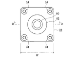
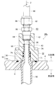
- FIG. 3 is a plan view showing the periphery of a flange in FIG. 2, and FIG. 2 is a cross-sectional view seen in the direction of line DD. It is the A section enlarged view in FIG. It is sectional drawing which shows other embodiment of the pipe holding
- FIG. 1 is a cross-sectional view showing an embodiment of a high-frequency antenna device according to the present invention.
- FIG. 6 is a cross-sectional view showing another embodiment of the high-frequency antenna device according to the present invention, in which the CC section follows the C′-C ′ section.
- FIG. 9 is an enlarged cross-sectional view illustrating an example of one hollow insulator and a capacitor in FIG. 8.
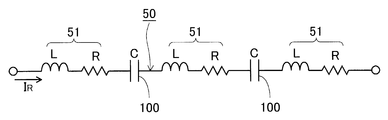
- FIG. 9 is an electrical equivalent circuit diagram of the high-frequency antenna device shown in FIG. 8. It is a schematic sectional drawing which shows an example of the inductively coupled plasma processing apparatus provided with the high frequency antenna apparatus which concerns on this invention.
- FIG. 2 shows an embodiment of a pipe holding connection structure according to the present invention.
- This pipe holding and connecting structure 30 a is a structure in which the pipe (the first pipe 50 in this embodiment) through which the fluid 2 flows flows through the opening 6 of the vacuum vessel 4.
- the vacuum vessel 4 is made of metal, for example.
- the opening 6 may be formed directly in the vacuum vessel 4 or may be formed in a flange attached to the vacuum vessel 4. Since the flange in the latter case can be regarded as a part of the vacuum vessel 4, both cases are collectively referred to as the opening 6 of the vacuum vessel 4 in this application.
- the soot fluid 2 is a liquid or a gas.
- a coolant such as cooling water may be employed as the fluid 2.
- High-frequency antenna devices 90a and 90b shown in FIGS. 7 and 8 are examples in this case.
- various gases may be employed as the fluid 2.
- the housing 32 is fixed to the outer wall of the vacuum vessel 4 by using four bolts 34 so as to airtightly close the opening 6.
- An example of the planar arrangement of the bolts 34 is shown in FIG. If the bolts 34 are arranged at the four corners of the housing 32 as in this example, the width W of the housing 32 can be further reduced.
- a packing 71 is provided between the housing 32 and the vacuum container 4 to vacuum-seal the two.
- the housing 32 is made of metal, for example, but may be made of an insulator (this will be described later).
- the eaves packing 71 is, for example, an O-ring, but other packings may be used. The same applies to the other packings 72 to 77 described later.
- the pipe 50 has a male screw portion 56 at its end.
- the first pipe 50 further has a locking portion 52 in the vicinity of the end portion thereof, which engages with the end portion of the housing 32 on the side of the vacuum vessel 4 and stops the movement of the pipe 50 in the outer direction of the vacuum vessel 4. Yes.
- An example of the locking portion 52 is shown in an enlarged manner in FIG.
- the housing 32 has a conical portion 35 around the end portion of the through hole 38 on the side of the vacuum vessel 4, and the pipe 50 has a shape corresponding to the conical portion 35 on the outer peripheral portion thereof.
- a conical portion 53 that stops the movement of the pipe 50 toward the outer side of the vacuum vessel 4 is engaged with the shape portion 35.
- the central axis of the pipe 50 can be easily aligned with the central axis of the housing 32 (specifically, the through hole 38).
- locking part 52 may have the flat parts 36 and 54 like the example shown in FIG.
- the movement of the first pipe 50 in the axial direction the movement of the first pipe 50 toward the outside of the vacuum vessel 4 can be stopped by the locking portion 52.
- the movement of the pipe 50 in the opposite direction can be permitted, for example, due to thermal expansion.
- a packing 72 for vacuum-sealing between the two housings 32 and the first pipe 50 is provided.
- This pipe holding and connecting structure 30a further includes a second pipe 60 that is provided outside the vacuum vessel 4 and through which the fluid 2 flows.
- the pipe 60 has a female threaded portion 64 that is screwed into the male threaded portion 56 of the first pipe 50 and connects the pipes 50, 60 at the end thereof.
- the female screw portion 64 is formed in a female connector 62 provided at the end of the pipe 60.
- a packing 73 is provided between the end of the first pipe 50 and the end of the second pipe 60 to seal (seal) the two.
- the material of the first pipe 50 and the second pipe 60 is, for example, a metal such as copper, aluminum, alloys thereof, and stainless steel, but is not limited thereto. The same applies to other embodiments described later.
- the material in the case where the housing 32 is made of metal is also the same as described above, for example.
- the pipe holding and connecting structure 30a can hold the first pipe 50 with respect to the vacuum vessel 4 and connect the first pipe 50 and the second pipe 60 by the structure as described above. Accordingly, the fluid 2 can be supplied from the pipe 60 to the pipe 50 or vice versa.
- the pipe holding and connecting structure 30a is a structure in which the male threaded portion 56 at the end of the first pipe 50 and the female threaded portion 64 at the end of the second pipe 60 are screwed together to connect the pipes 50 and 60 together. Therefore, the first pipe 50 and the second pipe 60 are connected to each other while securing the sealing performance by the packing 73 between the two pipes 50 and 60 without using stud bolts and nuts as in the prior art. be able to. As a result, the width W (see FIG. 3) of the entire structure 30a can be reduced, and the number of parts and the assembly work process can be reduced as compared with the case where stud bolts and nuts are used.
- FIG. 1 Another embodiment of the pipe holding and connecting structure is shown in FIG. Portions that are the same as or correspond to those of the pipe holding and connecting structure 30a are denoted by the same reference numerals, and differences from them will be mainly described below.
- the housing 32 constituting the pipe holding and connecting structure 30b shown in FIG. 5 has a through hole 38 and a first female screw part 40 and a second female screw part 42 connected to the through hole 38 therein.
- the structure for fixing the housing 32 to the outer wall of the vacuum vessel 4 so as to hermetically close the opening 6 is the same as in the case of the pipe holding connection structure 30a.
- the vicinity of the end of the first pipe 50 provided in the vacuum vessel 4 passes through the opening 6 of the vacuum vessel 4.
- the pipe 50 has a male threaded portion 58 at its end that is screwed into the first female threaded portion 40 of the housing 32 to connect the pipe 50 and the housing 32.
- the first pipe 50 further has a locking portion 52 in the vicinity of the end portion thereof, which engages with the end portion of the housing 32 on the side of the vacuum vessel 4 and stops the movement of the pipe 50 in the outer direction of the vacuum vessel 4.
- the housing 32 has a flat portion 36 around the end portion of the through-hole 38 on the side of the vacuum vessel 4, and the pipe 50 is engaged with the flat portion 36 on the outer peripheral portion of the pipe 50.
- the flat part 54 which stops the movement to the vacuum vessel 4 outer side direction is provided.
- the locking portion 52 may have the cone-shaped parts 35 and 53 like the example shown in FIG. 2, FIG.
- the movement of the first pipe 50 toward the outside of the vacuum vessel 4 can be stopped by the locking portion 52. Further, since the male threaded portion 58 at the end of the first pipe 50 and the first female threaded portion 40 of the housing 32 are screwed together, the first pipe 50 cooperates with the locking portion 52. It is possible to stop the movement in the axial direction more reliably. In addition, the center axis of the pipe 50 can be reliably aligned with the center axis of the housing 32.
- a packing 74 that vacuum seals between the two housings 32 and the first pipe 50 is provided.
- This pipe holding and connecting structure 30b includes a second pipe 60 that is provided outside the vacuum vessel 4 and through which the fluid 2 flows.
- the pipe holding and connecting structure 30b further includes a joint 80 for connecting the second pipe 60 to the housing 32 in a state where the fluid 2 is sealed (sealed).
- the joint 80 has a pipe insertion hole 82 that is a portion connecting the end portions of the pipe 60 and a male thread portion 84 that is screwed into the second female thread portion 42 of the housing 32.
- the joint 80 is, for example, a known ferrule joint, and has a ferrule (clamping ring) therein.
- the end of the second pipe 60 is inserted into the pipe insertion hole 82 and the nut 86 is tightened.
- the pipe 60 and the joint 80 can be coupled.
- the joint 80 can be coupled to the housing 32 or the coupling can be removed.
- the joint 80 is not limited to a ferrule joint.
- the second female screw portion 42 of the housing 32 and the male screw portion 84 of the joint 80 may be ordinary parallel screws or taper screws. When a taper screw is used, sealing (sealing) performance can be further improved.
- the pipe holding and connecting structure 30b can hold the first pipe 50 with respect to the vacuum vessel 4 and connect the first pipe 50 and the second pipe 60 by the structure as described above. Accordingly, the fluid 2 can be supplied from the pipe 60 to the pipe 50 or vice versa.
- the pipe holding and connecting structure 30 b is configured such that the male screw portion 58 at the end of the first pipe 50 is screwed into the first female screw portion 40 of the housing 32 and is screwed into the second female screw portion 42 of the housing 32. Since the second pipe 60 is connected to the housing 32 by the joint 80, the first pipe 50 and the second pipe 60 can be connected to each other without using stud bolts and nuts as in the prior art. It is possible to connect while ensuring the sealing performance of the connecting portion. As a result, the width W (see FIG. 3) of the entire structure 30b can be reduced, and the number of parts and the assembly work process can be reduced as compared with the case where stud bolts and nuts are used.
- the second pipe 60 is connected to the housing 32 via the joint 80, the degree of freedom in selecting the shape, material, etc. of the second pipe 60 increases.
- a flexible tube or the like can be used as the second pipe 60, and the pipe 60 can be connected to the housing 32 in a bent state. Therefore, the arrangement of the pipe 60 is facilitated even in a narrow place.
- the pipe holding and connecting structures 30a and 30b can be used for, for example, a high frequency antenna device constituting a plasma processing apparatus or the like. This will be described in detail below.
- it can be used for an ion source or the like.
- it can be used for a feedthrough (current introduction terminal) for supplying a coolant and electric power to an electrode or filament provided in a vacuum vessel constituting an ion source.
- the first pipe 50 is connected directly or indirectly to the electrode or filament.
- FIG. 7 shows an embodiment of the high-frequency antenna device according to the present invention.
- the first pipe 50 provided in the vacuum vessel 4 is made of a conductor, and both ends thereof have two openings 6 provided on the wall surface of the vacuum vessel 4, respectively. It penetrates. More specifically, in this embodiment, the pipe 50 has a linear shape, and both ends thereof pass through two openings 6 provided on opposite wall surfaces of the vacuum vessel 4, respectively.
- the material of the first pipe 50 in this case is, for example, as described above, and among them, a material having a high conductivity such as copper, aluminum, or an alloy thereof is preferable.
- the pipe holding and connecting structure 30a described with reference to FIG. 2 and the like in the vicinity of each end of the first pipe 50 through each opening 6, and the housing 32 is made of an insulator. It has the structure which is.
- the material of the cage housing 32 is, for example, ceramics such as alumina, quartz, or engineering plastics such as polyphenine sulfide (PPS) or polyether ether ketone (PEEK), but is not limited thereto.
- ceramics such as alumina, quartz, or engineering plastics such as polyphenine sulfide (PPS) or polyether ether ketone (PEEK), but is not limited thereto.
- PPS polyphenine sulfide
- PEEK polyether ether ketone
- An insulator 92 that electrically insulates between the vacuum vessel 4 and the first pipe 50 is provided in each opening 6 of the vacuum vessel 4.
- the material of the insulator 92 is, for example, the one exemplified as the material of the housing 32, but is not limited thereto.
- the first pipe 50 functions as a high-frequency antenna when a high-frequency current I R (the direction of which is reversed with time) flows from a high-frequency power source (see, for example, the high-frequency power source 130 in FIG. 11). Electrical connections for the flow of high frequency current I R in the pipe 50, for example, when the pipe 50 of the portion protruding out of the housing 32 or the second pipe 60, is made of a conductor connected to the pipe 50 What is necessary is just to perform in the part of the pipe 60 which is.
- Pipe 50 in order to have resistance, it generates heat by passing a high frequency current I R (i.e., to generate Joule heat).
- I R i.e., to generate Joule heat
- the pipe 50 can be cooled by a fluid (for example, cooling water; the same applies hereinafter) 2 flowing in the pipe 50.
- the high frequency antenna device 90a it is possible to realize a high frequency antenna device that exhibits the same effect as the above-described effect that the pipe holding connection structure 30a exhibits.
- the portion of the first pipe 50 that functions as a high-frequency antenna that is located in the vacuum vessel 4 may be disposed in the insulating pipe 94.
- the material of the insulating pipe 94 is, for example, quartz, alumina, fluororesin, silicon nitride, silicon carbide, silicon or the like, but is not limited thereto.
- the first pipe 50 can be protected by the insulating pipe 94.
- the high-frequency antenna device 90a is used for plasma generation (see, for example, the plasma processing apparatus shown in FIG. 11)
- charged particles in the plasma can be prevented from entering the first pipe 50.
- the occurrence of metal contamination (metal contamination) with respect to plasma can be suppressed.
- the first pipe 50 is preferably disposed in the insulating pipe 94 via a space.
- the potential of the pipe 50 rises by flowing the high-frequency current I R through the pipe 50, the potential rise of the surface of the insulating pipe 94 can be suppressed.
- an increase in the plasma potential can be suppressed.
- a portion of the first pipe 50 that functions as a high-frequency antenna located in the vacuum vessel 4 is electrically connected by interposing one or more hollow insulators 96 in series.
- An example of an electrical equivalent circuit in that case is shown in FIG.
- each hollow insulator 96 is, for example, ceramics such as alumina, fluororesin, polyethylene (PE), engineering plastics such as polyphenine sulfide (PPS), polyether ether ketone (PEEK), etc. It is not limited.
- This high-frequency antenna device 90b has two hollow insulators 96 and two capacitors 100, and is an example in which the first pipe 50 is electrically divided into three sections 51. The number is not limited to this.
- Each capacitor 100 can also be cooled by the fluid 2 flowing in the pipe 50 mainly by heat conduction with the hollow insulator 96.
- FIG. 9 is an enlarged view of an example around one hollow insulator 96 and the capacitor 100 in FIG.
- the thickness is greatly enlarged as compared with other elements.
- screw portions 98 and 99 for coupling and packings 75 and 76 for sealing the fluid 2 are provided.
- Each capacitor 100 is (a) an electrode disposed on the outer periphery of the hollow insulator 96, and a first electrode 102 electrically connected to a section 51 connected to one side of the hollow insulator 96. And (b) an electrode disposed on the outer periphery of the hollow insulator 96 so as to overlap the first electrode 102 and electrically connected to the section 51 connected to the other side of the hollow insulator 96.
- Each capacitor 100 may have one layer each of the first electrode 102, the second electrode 104, and the dielectric 106 (FIG. 9 shows an example of this case), and each capacitor 100 has a plurality of layers. You may do it.
- the first pipe 50 functioning as a high frequency antenna is divided into a plurality of sections 51 by a hollow insulator 96, and the plurality of sections are formed by a capacitor 100 provided on the outer periphery of each hollow insulator 96.
- the combined reactance of the first pipe 50 is simply a form in which the capacitive reactance is subtracted from the inductive reactance. Impedance can be reduced.
- each section 51 is L
- the resistance is R
- the capacitance of each capacitor 100 is C.
- the inductance L and resistance R of each section 51 can be set to substantially the same value if each section 51 is made substantially the same length.
- the impedance Z of the first pipe 50 can be expressed by the following equation. ⁇ is an angular frequency of the high-frequency current I R , and j is an imaginary unit.
- the imaginary part of the above formula is the combined reactance of the first pipe 50, and has a form in which the capacitive reactance 2 / ⁇ C is subtracted from the inductive reactance 3 ⁇ L.
- the impedance Z of the pipe 50 can be reduced.
- the number of sections 51 and the number of capacitors 100 and the like can be selected as appropriate, so that the impedance Z of the first pipe 50 is designed to an appropriate value regardless of the length of the first pipe 50. can do.
- an increase in the impedance Z can be suppressed even when the first pipe 50 is lengthened. Therefore, it is possible to suppress the occurrence of a large potential difference between both ends of the first pipe 50. Further, even when the first pipe 50 is lengthened, an increase in the impedance Z can be suppressed, so that the high-frequency current I R easily flows through the first pipe 50.
- High frequency antenna device 90a or 90b as described above generates inductively coupled by an inductive electric field generated by flowing a high frequency current I R in the high frequency antenna plasma (abbreviated ICP), to a substrate using the plasma
- ICP high frequency antenna plasma
- the present invention can be used in an inductively coupled plasma processing apparatus that performs processing.
- a schematic example of such a plasma processing apparatus is shown in FIG.
- a substrate holder 124 for holding the substrate 122 to be processed is provided in the vacuum vessel 4 into which a required gas 126 is introduced through the gas introduction port 125 while being evacuated by the evacuation device 120.
- the high-frequency antenna device 90a or 90b is provided so that the linear first pipe 50 crosses the inside of the vacuum vessel 4 above the substrate 122. These 90a and 90b are illustrated very simply here.
- the frequency of the high-frequency current I R is, for example, a general 13.56 MHz, but is not limited thereto.
- a high-frequency magnetic field is generated around the first pipe 50, thereby generating an induced electric field in a direction opposite to the high-frequency current I R. Due to this induction electric field, electrons are accelerated in the vacuum vessel 4 to ionize the gas 126 in the vicinity of the first pipe 50 and generate plasma (ie, inductively coupled plasma) 128 in the vicinity of the first pipe 50. To do.
- the plasma 128 diffuses to the vicinity of the substrate 122, and the substrate 122 can be subjected to processing such as film formation by CVD or the like, etching, ashing, sputtering, and the like.
- two pipe holding and connecting structures 30b shown in FIG. 5 may be provided.
- FIG. 6 shows an example in which the pipe holding connection structure 30b is used in a high frequency antenna device.
- the pipe holding connection structure 30a is used in a high frequency antenna device.
- the housing 32 is made of metal, and an insulator 93 that electrically insulates the vacuum vessel 4 from the first pipe 50 and the housing 32 is provided around the opening 6 of the vacuum vessel 4 and the periphery thereof. ing.
- the insulator 93 is fixed to the vacuum vessel 4 with bolts 95, and the insulator 93 and the vacuum vessel 4 are vacuum sealed with a packing 77.
- the insulator 93 may be divided into an insulating material between the vacuum vessel 4 and the first pipe 50 and an insulating material between the vacuum vessel 4 and the housing 32.
- the material of the insulator 93 is the same as that of the insulator 92, for example, but is not limited thereto. Electrical connections for the flow of high frequency current I R in the pipe 50, for example, may be performed in a portion of the metallic housing 32.
- the high-frequency antenna device includes the two pipe holding and connecting structures 30b, a high-frequency antenna device that exhibits the same effect as the above-described effect of the pipe holding and connecting structure 30b can be realized.
- one of the two pipe holding connection structures constituting the high-frequency antenna devices 90a and 90b may be the pipe holding connection structure 30a, and the other may be the pipe holding connection structure 30b. If it does so, about the part provided with the pipe holding
Landscapes
- Engineering & Computer Science (AREA)
- General Engineering & Computer Science (AREA)
- Physics & Mathematics (AREA)
- Plasma & Fusion (AREA)
- Mechanical Engineering (AREA)
- Chemical & Material Sciences (AREA)
- Analytical Chemistry (AREA)
- Spectroscopy & Molecular Physics (AREA)
- Electromagnetism (AREA)
- General Chemical & Material Sciences (AREA)
- Chemical Kinetics & Catalysis (AREA)
- Materials Engineering (AREA)
- Metallurgy (AREA)
- Organic Chemistry (AREA)
- Plasma Technology (AREA)
- Branch Pipes, Bends, And The Like (AREA)
- Chemical Vapour Deposition (AREA)
- Drying Of Semiconductors (AREA)
Abstract
Description
図2に、この発明に係るパイプ保持接続構造の一実施形態を示す。
次に、上記パイプ保持接続構造30a、30bを備えている高周波アンテナ装置の実施形態を説明する。以下においては、上記パイプ保持接続構造30a、30bと同一または相当する部分には同一符号を付して、それとの相違点を主に説明する。
Z=3R+j(3ωL-2/ωC)
4 真空容器
6 開口部
30a、30b パイプ保持接続構造
32 ハウジング
38 貫通穴
40 第1の雌ねじ部
42 第2の雌ねじ部
50 第1のパイプ
52 係止部
56、58 雄ねじ部
60 第2のパイプ
64 雌ねじ部
80 継手
82 パイプ挿入穴
84 雄ねじ部
90a、90b 高周波アンテナ装置
92、93 絶縁物
94 絶縁パイプ
96 中空絶縁体
100 コンデンサ
Claims (7)
- 内部に流体が流されるパイプが真空容器の開口部を貫通している部分の構造であって、
前記真空容器の外壁に、前記開口部を気密に塞ぐように固定されたハウジングと、
前記真空容器内に設けられていて内部に前記流体が流される第1のパイプであって、その端部付近が前記真空容器の開口部および前記ハウジングを貫通しており、かつ当該端部付近に、前記ハウジングの真空容器側端部と係わり合って当該第1のパイプの真空容器外側方向への動きを止める係止部を有しており、更に端部に雄ねじ部を有している第1のパイプと、
前記ハウジングと前記第1のパイプとの間を真空シールするパッキンと、
前記真空容器外に設けられていて内部に前記流体が流される第2のパイプであって、その端部に、前記第1のパイプの雄ねじ部と螺合して両パイプを接続する雌ねじ部を有している第2のパイプと、
前記第1のパイプの端部と前記第2のパイプの端部との間をシールするパッキンとを備えている、ことを特徴とするパイプ保持接続構造。 - 内部に流体が流されるパイプが真空容器の開口部を貫通している部分の構造であって、
前記真空容器の外壁に、前記開口部を気密に塞ぐように固定されたハウジングであって、その内部に貫通穴ならびに当該貫通穴につながる第1の雌ねじ部および第2の雌ねじ部を有しているハウジングと、
前記真空容器内に設けられていて内部に前記流体が流される第1のパイプであって、その端部付近が前記真空容器の開口部を貫通しており、かつ当該端部付近に、前記ハウジングの真空容器側端部と係わり合って当該第1のパイプの真空容器外側方向への動きを止める係止部を有しており、更に端部に、前記ハウジングの第1の雌ねじ部と螺合して当該第1のパイプと前記ハウジングとを接続する雄ねじ部を有している第1のパイプと、
前記ハウジングと前記第1のパイプとの間を真空シールするパッキンと、
前記真空容器外に設けられていて内部に前記流体が流される第2のパイプと、
前記第2のパイプの端部を接続する部分および前記ハウジングの第2の雌ねじ部と螺合する雄ねじ部を有していて、前記第2のパイプを前記ハウジングに、前記流体をシールした状態で接続する継手とを備えている、ことを特徴とするパイプ保持接続構造。 - 前記第1のパイプは導体から成り、その両端部付近が前記真空容器の壁面に設けられた二つの開口部をそれぞれ貫通しており、
前記第1のパイプの各端部付近が前記各開口部を貫通している部分に、請求項1記載のパイプ保持接続構造であって前記ハウジングが絶縁物製である構造を備えており、
前記真空容器の各開口部には、前記真空容器と前記第1のパイプとの間を電気絶縁する絶縁物が設けられており、
かつ前記第1のパイプは、それに高周波電流が流されて高周波アンテナとして機能するものである、ことを特徴とする高周波アンテナ装置。 - 前記第1のパイプは導体から成り、その両端部付近が前記真空容器の壁面に設けられた二つの開口部をそれぞれ貫通しており、
前記第1のパイプの各端部付近が前記各開口部を貫通している部分に、請求項2記載のパイプ保持接続構造であって前記ハウジングが金属製である構造を備えており、
前記真空容器の各開口部およびその周りには、前記真空容器と前記第1のパイプおよび前記ハウジングとの間を電気絶縁する絶縁物が設けられており、
かつ前記第1のパイプは、それに高周波電流が流されて高周波アンテナとして機能するものである、ことを特徴とする高周波アンテナ装置。 - 前記第1のパイプは導体から成り、その両端部付近が前記真空容器の壁面に設けられた二つの開口部をそれぞれ貫通しており、
前記第1のパイプの一方の端部付近が前記開口部を貫通している部分に、請求項1記載のパイプ保持接続構造であって前記ハウジングが絶縁物製である構造を備えており、かつ当該真空容器の開口部には、当該真空容器と前記第1のパイプとの間を電気絶縁する絶縁物が設けられており、
前記第1のパイプの他方の端部付近が前記開口部を貫通している部分に、請求項2記載のパイプ保持接続構造であって前記ハウジングが金属製である構造を備えており、かつ当該真空容器の開口部およびその周りには、当該真空容器と前記第1のパイプおよび前記ハウジングとの間を電気絶縁する絶縁物が設けられており、
かつ前記第1のパイプは、それに高周波電流が流されて高周波アンテナとして機能するものである、ことを特徴とする高周波アンテナ装置。 - 前記第1のパイプの前記真空容器内に位置する部分は、1以上の中空絶縁体を直列に介在させることによって電気的に複数区分に分割されており、
かつ前記各中空絶縁体の外周部に層状のコンデンサをそれぞれ設けて、当該コンデンサを介して、前記複数区分を電気的に直列接続している請求項3、4または5記載の高周波アンテナ装置。 - 前記第1のパイプの前記真空容器内に位置する部分は、絶縁パイプ内に配置されている請求項3、4、5または6記載の高周波アンテナ装置。
Priority Applications (4)
| Application Number | Priority Date | Filing Date | Title |
|---|---|---|---|
| CN201680007653.XA CN107208833B (zh) | 2015-01-28 | 2016-01-22 | 管路保持连接结构以及具备所述结构的高频天线装置 |
| KR1020177020941A KR101981072B1 (ko) | 2015-01-28 | 2016-01-22 | 파이프 유지 접속 구조 및 그것을 구비하는 고주파 안테나 장치 |
| US15/546,664 US9897236B2 (en) | 2015-01-28 | 2016-01-22 | Pipe holding connection structure and high frequency antenna device including the same |
| MYPI2017001151A MY185268A (en) | 2015-03-30 | 2016-03-29 | Pyrazole derivative useful as pi3k inhibitor |
Applications Claiming Priority (2)
| Application Number | Priority Date | Filing Date | Title |
|---|---|---|---|
| JP2015013920A JP6471515B2 (ja) | 2015-01-28 | 2015-01-28 | パイプ保持接続構造およびそれを備える高周波アンテナ装置 |
| JP2015-013920 | 2015-01-28 |
Publications (1)
| Publication Number | Publication Date |
|---|---|
| WO2016121626A1 true WO2016121626A1 (ja) | 2016-08-04 |
Family
ID=56543239
Family Applications (1)
| Application Number | Title | Priority Date | Filing Date |
|---|---|---|---|
| PCT/JP2016/051762 Ceased WO2016121626A1 (ja) | 2015-01-28 | 2016-01-22 | パイプ保持接続構造およびそれを備える高周波アンテナ装置 |
Country Status (6)
| Country | Link |
|---|---|
| US (1) | US9897236B2 (ja) |
| JP (1) | JP6471515B2 (ja) |
| KR (1) | KR101981072B1 (ja) |
| CN (1) | CN107208833B (ja) |
| TW (1) | TWI546485B (ja) |
| WO (1) | WO2016121626A1 (ja) |
Cited By (1)
| Publication number | Priority date | Publication date | Assignee | Title |
|---|---|---|---|---|
| US20170314710A1 (en) * | 2016-04-28 | 2017-11-02 | Asm Automation Sensorik Messtechnik Gmbh | Screw connection |
Families Citing this family (17)
| Publication number | Priority date | Publication date | Assignee | Title |
|---|---|---|---|---|
| FR3054613B1 (fr) * | 2016-07-29 | 2020-04-10 | Sogefi Air & Refroidissement France | Repartiteur d'admission a echangeur de chaleur integre |
| JP6615069B2 (ja) * | 2016-08-29 | 2019-12-04 | 東京エレクトロン株式会社 | 懸垂型インジェクタの支持構造及びこれを用いた基板処理装置 |
| CN108933074B (zh) * | 2017-05-24 | 2020-06-19 | 北京北方华创微电子装备有限公司 | 进气装置和包括该进气装置的腔室 |
| JP7025711B2 (ja) * | 2018-03-14 | 2022-02-25 | 日新電機株式会社 | アンテナ及びプラズマ処理装置 |
| JP7101335B2 (ja) * | 2018-03-19 | 2022-07-15 | 日新電機株式会社 | アンテナ及びプラズマ処理装置 |
| JP7061264B2 (ja) | 2018-03-20 | 2022-04-28 | 日新電機株式会社 | プラズマ制御システム及びプラズマ制御システム用プログラム |
| GB2572553A (en) * | 2018-03-29 | 2019-10-09 | Airbus Operations Ltd | Aircraft fuel tank isolator |
| US11145496B2 (en) * | 2018-05-29 | 2021-10-12 | Varian Semiconductor Equipment Associates, Inc. | System for using O-rings to apply holding forces |
| US10830077B2 (en) | 2018-07-17 | 2020-11-10 | Raytheon Technologies Corporation | Sealing configuration to reduce air leakage |
| US10781710B2 (en) | 2018-07-17 | 2020-09-22 | Raytheon Technologies Corporation | Sealing configuration to reduce air leakage |
| JP7352068B2 (ja) | 2019-07-12 | 2023-09-28 | 日新電機株式会社 | プラズマ制御システム |
| CN111022777A (zh) * | 2019-12-02 | 2020-04-17 | 贵州凯星液力传动机械有限公司 | 一种液压油管密封装置 |
| DE102021206281A1 (de) | 2021-06-18 | 2022-12-22 | Trumpf Lasersystems For Semiconductor Manufacturing Gmbh | Gehäuseanordnung und Dichtsystem |
| CN114530261A (zh) * | 2022-01-27 | 2022-05-24 | 中国科学院合肥物质科学研究院 | 一种用于超高真空环境下的密封圈密封结构 |
| DE112023002182T5 (de) * | 2022-05-10 | 2025-04-30 | Nissin Electric Co., Ltd. | Filmbildungsvorrichtung und Filmbildungsverfahren |
| DE102023101875B4 (de) * | 2023-01-26 | 2026-01-15 | Bayerische Motoren Werke Aktiengesellschaft | Kühleinrichtung zum Kühlen einer elektronischen Recheneinrichtung für ein Kraftfahrzeug sowie Kraftfahrzeug |
| DE102024113391A1 (de) | 2024-05-14 | 2025-11-20 | VON ARDENNE Asset GmbH & Co. KG | Vakuumanordnung |
Citations (6)
| Publication number | Priority date | Publication date | Assignee | Title |
|---|---|---|---|---|
| JPH0131831Y2 (ja) * | 1984-05-31 | 1989-09-29 | ||
| JPH0140225Y2 (ja) * | 1983-06-24 | 1989-12-01 | ||
| JPH07208656A (ja) * | 1994-01-28 | 1995-08-11 | Osaka Gas Co Ltd | 水切り部のガス管の改修方法 |
| JPH08165572A (ja) * | 1994-12-14 | 1996-06-25 | Nissin Electric Co Ltd | 真空処理室における通水装置 |
| US20060099843A1 (en) * | 2004-11-01 | 2006-05-11 | Fullner Todd C | Dielectric fittings |
| JP2011241917A (ja) * | 2010-05-19 | 2011-12-01 | Nissin Electric Co Ltd | 真空シールおよび配管接続機構 |
Family Cites Families (7)
| Publication number | Priority date | Publication date | Assignee | Title |
|---|---|---|---|---|
| US4542846A (en) * | 1982-03-16 | 1985-09-24 | Kawasaki Jukogyo Kabushiki Kaisha | Method of producing a multiple-wall pipe structure with anticorrosion end protection |
| US4914177A (en) | 1987-07-13 | 1990-04-03 | American Telephone And Telegraph Company | Polyquinoxaline polymers, and articles comprising same |
| JPS6440225A (en) | 1987-08-04 | 1989-02-10 | Fujitsu Ltd | Manufacture of metal mold for molding |
| US7784835B1 (en) * | 2006-12-05 | 2010-08-31 | Keays Steven J | Pipe connecting member |
| GB0701600D0 (en) * | 2007-01-27 | 2007-03-07 | Deep Tek Ltd | Apparatus and method |
| JP5421551B2 (ja) * | 2008-06-11 | 2014-02-19 | 東京エレクトロン株式会社 | プラズマ処理装置及びプラズマ処理方法 |
| US9508526B2 (en) * | 2013-12-13 | 2016-11-29 | Ebara Corporation | Top opening-closing mechanism and inspection apparatus |
-
2015
- 2015-01-28 JP JP2015013920A patent/JP6471515B2/ja active Active
-
2016
- 2016-01-22 CN CN201680007653.XA patent/CN107208833B/zh active Active
- 2016-01-22 US US15/546,664 patent/US9897236B2/en active Active
- 2016-01-22 KR KR1020177020941A patent/KR101981072B1/ko active Active
- 2016-01-22 WO PCT/JP2016/051762 patent/WO2016121626A1/ja not_active Ceased
- 2016-01-27 TW TW105102427A patent/TWI546485B/zh active
Patent Citations (6)
| Publication number | Priority date | Publication date | Assignee | Title |
|---|---|---|---|---|
| JPH0140225Y2 (ja) * | 1983-06-24 | 1989-12-01 | ||
| JPH0131831Y2 (ja) * | 1984-05-31 | 1989-09-29 | ||
| JPH07208656A (ja) * | 1994-01-28 | 1995-08-11 | Osaka Gas Co Ltd | 水切り部のガス管の改修方法 |
| JPH08165572A (ja) * | 1994-12-14 | 1996-06-25 | Nissin Electric Co Ltd | 真空処理室における通水装置 |
| US20060099843A1 (en) * | 2004-11-01 | 2006-05-11 | Fullner Todd C | Dielectric fittings |
| JP2011241917A (ja) * | 2010-05-19 | 2011-12-01 | Nissin Electric Co Ltd | 真空シールおよび配管接続機構 |
Cited By (2)
| Publication number | Priority date | Publication date | Assignee | Title |
|---|---|---|---|---|
| US20170314710A1 (en) * | 2016-04-28 | 2017-11-02 | Asm Automation Sensorik Messtechnik Gmbh | Screw connection |
| US10746327B2 (en) * | 2016-04-28 | 2020-08-18 | Asm Automation Sensorik Messtechnik Gmbh | Screw connection |
Also Published As
| Publication number | Publication date |
|---|---|
| TWI546485B (zh) | 2016-08-21 |
| US20170370504A1 (en) | 2017-12-28 |
| KR20170097205A (ko) | 2017-08-25 |
| JP2016138598A (ja) | 2016-08-04 |
| KR101981072B1 (ko) | 2019-05-22 |
| TW201631273A (zh) | 2016-09-01 |
| JP6471515B2 (ja) | 2019-02-20 |
| CN107208833B (zh) | 2019-01-11 |
| CN107208833A (zh) | 2017-09-26 |
| US9897236B2 (en) | 2018-02-20 |
Similar Documents
| Publication | Publication Date | Title |
|---|---|---|
| JP6471515B2 (ja) | パイプ保持接続構造およびそれを備える高周波アンテナ装置 | |
| TWI580324B (zh) | 電漿產生用的天線及具備該天線的電漿處理裝置 | |
| JP6341329B1 (ja) | プラズマ発生用のアンテナ及びそれを備えるプラズマ処理装置 | |
| US10932353B2 (en) | Antenna for generating plasma, and plasma treatment device and antenna structure provided with antenna for generating plasma | |
| TWI708526B (zh) | 天線以及電漿處理裝置 | |
| JP6931461B2 (ja) | プラズマ発生用のアンテナ、それを備えるプラズマ処理装置及びアンテナ構造 | |
| US3435128A (en) | Replaceable vacuum-tight current feedthroughs | |
| TWI584343B (zh) | Plasma processing device | |
| US7056388B2 (en) | Reaction chamber with at least one HF feedthrough | |
| JP2017004602A (ja) | プラズマ発生用のアンテナおよびそれを備えるプラズマ処理装置 | |
| KR20220027091A (ko) | 심리스 전기 도관 | |
| TWI723353B (zh) | 天線以及電漿處理裝置 | |
| WO2018151114A1 (ja) | プラズマ発生用のアンテナ、それを備えるプラズマ処理装置及びアンテナ構造 | |
| US20060279083A1 (en) | Arrangement for connecting a fiber-reinforced plastic pipe to a stainless steel flange | |
| JP2024100104A (ja) | アンテナ装置及びプラズマ処理装置 | |
| JP7028001B2 (ja) | 成膜方法 | |
| TW202549421A (zh) | 電漿處理裝置 | |
| WO2023139957A1 (ja) | アンテナ及びプラズマ処理装置 |
Legal Events
| Date | Code | Title | Description |
|---|---|---|---|
| 121 | Ep: the epo has been informed by wipo that ep was designated in this application |
Ref document number: 16743229 Country of ref document: EP Kind code of ref document: A1 |
|
| ENP | Entry into the national phase |
Ref document number: 20177020941 Country of ref document: KR Kind code of ref document: A |
|
| WWE | Wipo information: entry into national phase |
Ref document number: 15546664 Country of ref document: US |
|
| NENP | Non-entry into the national phase |
Ref country code: DE |
|
| 122 | Ep: pct application non-entry in european phase |
Ref document number: 16743229 Country of ref document: EP Kind code of ref document: A1 |