WO2016121504A1 - 不織布外装材、不織布外装材付ワイヤーハーネス、及び、不織布外装材付ワイヤーハーネスの製造方法 - Google Patents
不織布外装材、不織布外装材付ワイヤーハーネス、及び、不織布外装材付ワイヤーハーネスの製造方法 Download PDFInfo
- Publication number
- WO2016121504A1 WO2016121504A1 PCT/JP2016/050924 JP2016050924W WO2016121504A1 WO 2016121504 A1 WO2016121504 A1 WO 2016121504A1 JP 2016050924 W JP2016050924 W JP 2016050924W WO 2016121504 A1 WO2016121504 A1 WO 2016121504A1
- Authority
- WO
- WIPO (PCT)
- Prior art keywords
- nonwoven fabric
- exterior material
- belt
- fabric exterior
- thickness
- Prior art date
- Legal status (The legal status is an assumption and is not a legal conclusion. Google has not performed a legal analysis and makes no representation as to the accuracy of the status listed.)
- Ceased
Links
Images




Classifications
-
- H—ELECTRICITY
- H01—ELECTRIC ELEMENTS
- H01B—CABLES; CONDUCTORS; INSULATORS; SELECTION OF MATERIALS FOR THEIR CONDUCTIVE, INSULATING OR DIELECTRIC PROPERTIES
- H01B7/00—Insulated conductors or cables characterised by their form
-
- H—ELECTRICITY
- H02—GENERATION; CONVERSION OR DISTRIBUTION OF ELECTRIC POWER
- H02G—INSTALLATION OF ELECTRIC CABLES OR LINES, OR OF COMBINED OPTICAL AND ELECTRIC CABLES OR LINES
- H02G3/00—Installations of electric cables or lines or protective tubing therefor in or on buildings, equivalent structures or vehicles
- H02G3/02—Details
- H02G3/04—Protective tubing or conduits, e.g. cable ladders or cable troughs
Definitions
- This invention relates to a non-woven fabric exterior material attached to a wire harness.
- Patent Document 1 discloses a method for manufacturing a wire protection structure, in which a strip-shaped nonwoven material is wound around an electric wire bundle to cover the electric wire bundle, and the nonwoven material in the wound form is heated and compressed. Is disclosed.
- the strip-shaped nonwoven material is wound around the wire bundle while being overlapped, for example, while shifting by half the width dimension.
- variation will generate
- the thickness of the nonwoven material in the wound form may vary.
- the surface of the nonwoven material may be uneven. Therefore, there is a possibility that the non-woven material is likely to be damaged by repeatedly contacting with other members such as a vehicle body panel in which the wire harness is arranged.
- an object of the present invention is to provide a technique for reducing variations in the thickness of a nonwoven fabric exterior material in a form wound around a wire harness.
- the first aspect is a nonwoven fabric exterior material wound around a wire harness, the first strip extending in the longitudinal direction of the nonwoven fabric exterior material, and the longitudinal direction of the nonwoven fabric exterior material A second belt-like portion extending; and an intermediate portion in which the first belt-like portion is continuous with an end portion on one side in the width direction of the nonwoven fabric exterior material, and the second belt-like portion is continuous with an end portion on the other side in the width direction.
- the thickness of the intermediate portion is larger than the thickness of the first strip portion and the thickness of the second strip portion.
- the second aspect is a nonwoven fabric exterior material according to the first aspect, wherein the width of the first belt-like portion and the width of the second belt-like portion are the same.
- the third aspect is a nonwoven fabric exterior material according to the first or second aspect, and in the intermediate part, the end part on the one side in the width direction where the base end part of the first belt-like part is continuous, And the position of the edge part of the said width direction other side where the base end part of the said 2nd strip
- a 4th aspect is a nonwoven fabric exterior material which concerns on a 3rd aspect, Comprising: The edge part of the said width direction one side is an edge part of the one side of the said thickness direction in the said intermediate part, The said width direction The other end is the other end of the intermediate portion in the thickness direction.
- the fifth aspect is the nonwoven fabric exterior material according to any one of the first to fourth aspects, wherein the thickness when the first belt-shaped portion and the second belt-shaped portion are overlapped with each other is It is the same as the thickness of the middle part.
- a sixth aspect is a nonwoven fabric exterior material according to any one of the first to fifth aspects, wherein a convex part is formed on one side surface of the first belt-like part, and the second part A concave portion having a size allowing the convex portion to enter is formed on the other side surface of the belt-like portion.
- the seventh aspect is a nonwoven fabric exterior material according to the sixth aspect, wherein the convex portion and the concave portion extend in the longitudinal direction of the nonwoven fabric exterior material.
- an 8th aspect is a wire harness with a nonwoven fabric exterior material of the form by which the strip
- the said nonwoven fabric exterior material is the 1st extended in the longitudinal direction of the said nonwoven fabric exterior material.
- 1 band-like part, the 2nd belt-like part extended in the longitudinal direction of the nonwoven fabric exterior material, and the 1st belt-like part are continuing to the width direction one side part of the nonwoven fabric exterior material, and the width direction other side part is the first
- a 9th aspect is a manufacturing method of the wire harness with a nonwoven fabric exterior material of the form by which the strip
- the band-shaped portion, the second band-shaped portion extending in the longitudinal direction of the nonwoven fabric exterior material, and the first belt-shaped portion is continuous with one side portion in the width direction of the nonwoven fabric exterior material, and the second portion in the width direction other side portion.
- a step of preparing a non-woven fabric exterior material comprising: an intermediate portion having a continuous belt-like portion, wherein the thickness of the intermediate portion is larger than the thickness of the first belt-like portion and the thickness of the second belt-like portion; b) winding the non-woven fabric exterior material around the wire harness so that the first belt-like portion overlaps the surface of the second belt-like portion previously wound around the wire harness.
- the thickness of the overlapping portion is larger than the thickness of the intermediate portion. It can be suppressed from becoming extremely large. For this reason, the dispersion
- the first strip portion can be overlapped with the second strip portion over the entire width direction.
- the base end portion of the first strip portion and the base end portion of the second strip portion are different from each other in the thickness direction at the position where the base portion is continuous with the intermediate portion.
- nonwoven fabric exterior material according to the fourth aspect, it is possible to effectively suppress the warp of the first belt-like portion or the second belt-like portion when the first belt-like portion and the second belt-like portion are overlapped.
- the thickness of the overlapping portion of the first belt-like portion and the second belt-like portion and the thickness of the intermediate portion can be made the same. For this reason, the dispersion
- belt shape are wound by winding a nonwoven fabric exterior material around a wire harness, inserting the convex part of a 1st strip
- FIG. 1 is a schematic perspective view showing a nonwoven fabric exterior material 10 according to the first embodiment.
- FIG. 2 is a schematic front view according to the nonwoven fabric exterior material 10 according to the first embodiment.
- FIG. 3 is a schematic perspective view showing a state before the nonwoven fabric exterior material 10 according to the first embodiment is wound around the wire harness 20.
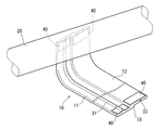
- FIG. 4 is a schematic perspective view showing a state in which the nonwoven fabric exterior material 10 according to the first embodiment is wound around the wire harness 20.
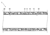
- FIG. 5 is a schematic cross-sectional view illustrating a part of the wire harness 1 with the nonwoven fabric exterior material according to the first embodiment.
- the longitudinal direction of the nonwoven fabric exterior material 10 indicated by the arrow AR1 is simply referred to as “longitudinal direction”.
- the width direction of the nonwoven fabric exterior material 10 indicated by the arrow AR2 is simply referred to as “width direction”.
- the width direction is a direction orthogonal to the longitudinal direction.
- the thickness direction of the nonwoven fabric exterior material 10 indicated by the arrow AR3 is simply referred to as “thickness direction”.
- the thickness direction is a direction orthogonal to both the longitudinal direction and the width direction.
- the surface side of the nonwoven fabric exterior material 10 that faces the outer peripheral surface of the wire harness 20 is referred to as “thickness direction upper side”, and the opposite side is referred to as “thickness direction lower side”. Referred to as “side”.
- Nonwoven fabric exterior material 10 is a member formed by heating and compressing a nonwoven fabric.
- heat compression refers to molding a thermoplastic resin by sandwiching a thermoplastic material to be processed between molds and applying pressure while the mold is heated.
- die for heat-compressing is not limited to what is comprised with two metal mold
- the thermoplastic material is a material that is partially or wholly melted or softened when heated and hardened when cooled.
- the thermoplastic material is molded and processed in a state of being heated and melted or softened, and then cooled, thereby maintaining a predetermined shape.
- a non-woven material is used as the thermoplastic material.
- the nonwoven material a material that is partially or wholly melted or softened through a heating process and then cured through a cooling process may be used.
- a material containing basic fibers and an adhesive resin also referred to as a binder
- the adhesive resin has a melting point lower than the melting point of the basic fiber.
- the basic fibers of the nonwoven material resin fibers or other fibers can be adopted as long as the transition state can be maintained at the melting point of the adhesive resin.
- the adhesive resin a thermoplastic resin having a melting point lower than the melting point of the basic fiber can be employed.
- the basic fiber is a resin fiber of PET (polyethylene terephthalate)
- the adhesive resin is a copolymer resin of PET and PEI (polyethylene isophthalate).
- the nonwoven fabric exterior material 10 is a molded product formed by heating and compressing, but in the longitudinal direction, the nonwoven fabric exterior material 10 has flexibility enough to allow the operator to manually roll it.
- the nonwoven fabric exterior material 10 includes a first strip portion 11, a second strip portion 13, and an intermediate portion 15.
- belt-shaped part 13 are parts extended along the longitudinal direction of the nonwoven fabric exterior material 10, and have a part parallel to the width direction.
- the first strip portion 11 and the second strip portion 13 are connected via an intermediate portion 15 therebetween. Further, the width (size in the width direction) of the first belt-like portion 11 is substantially the same as the width of the second belt-like portion 13.
- the width direction base end portion of the first strip portion 11 is continuous with the width portion one side portion 151 of the intermediate portion 15. Further, the width direction base end portion of the second belt-like portion 13 is continuous with the width portion other side portion 153 of the intermediate portion 15.
- the position where the base end portion of the first strip portion 11 and the base end portions of the base end portion and the second strip portion continue to the intermediate portion 15 are different in the thickness direction.
- the portion 151 on one side in the width direction where the first belt-like portion 11 continues is an end portion on the lower side in the thickness direction of the intermediate portion 15 (on the one side in the thickness direction). End).
- belt-shaped part 11 and the lower surface of the intermediate part 15 are flush
- a portion 153 on the other side in the width direction in which the second belt-like portion 13 continues is an end portion on the upper side in the thickness direction of the intermediate portion 15 (an end portion on the other side in the thickness direction).
- belt-shaped part 13 and the upper surface of the intermediate part 15 are flush
- a convex portion 31 that protrudes upward in the thickness direction over the longitudinal direction is provided in the center portion in the width direction of the first strip portion 11.
- the convex portion 31 has a substantially semicircular cross section (cut cut along a plane perpendicular to the longitudinal direction).
- a concave portion 33 is provided at the center in the width direction of the second belt-shaped portion 13 so as to be recessed upward in the thickness direction over the longitudinal direction.
- the concave portion 33 has a substantially semicircular shape corresponding to the convex portion 31 in a cross-sectional view.
- “corresponding” means that at least the concave portion 33 has a size capable of inserting the convex portion 31.
- the width of the concave portion 33 (the size in the width direction) is not necessarily larger than the width of the convex portion 31.
- the width of the concave portion 33 is made smaller than the width of the convex portion 31, it is possible to make it difficult for the convex portion 31 inserted into the concave portion 33 to come out.
- the shape of the convex portion 31 and the concave portion 33 does not necessarily have to be a substantially semicircular shape in a cross-sectional view.
- an elliptical shape, a square shape (including a rectangular shape), a rounded corner shape, or a combination thereof may be used.
- the shape in the cross-sectional view of the convex part 31 and the concave part 33 does not necessarily need to be similar.
- the convex portion 31 does not necessarily have to extend in parallel to the longitudinal direction.
- the convex portion 31 may extend in the synthesis direction having a longitudinal component and a width component.
- the direction where a convex-shaped part is extended in a longitudinal direction like this embodiment is preferable.
- the concave portion (including a plurality of concave portions corresponding to the plurality of protrusions) is made corresponding to the position, size, and shape of the convex portion (including a plurality of protrusions). It is good to provide.
- adhesive materials 40 are respectively attached to the upper surfaces in the thickness direction in the vicinity of both ends of the first strip portion 11 and the second strip portion 13.
- a double-sided pressure-sensitive adhesive tape is suitable as the adhesive material.
- one end of the nonwoven fabric exterior material 10 is bonded to the wire harness 20 via the adhesive materials 40 and 40. Then, as shown in FIG. 4, the other part of the nonwoven fabric exterior material 10 is wound around the wire harness 20.
- the portion of the first belt-like portion 11 to be wound is overlapped on the upper side of the second belt-like portion 13 that has been wound around.
- the front end of the first band-shaped portion 11 is connected to the side surface on the other side in the width direction of the intermediate portion 15 wound first (the surface on which the base end portion of the second band-shaped portion 13 continues. ). Thereby, it is possible to suppress a gap from being formed between the intermediate portion 15 and the first belt-like portion 11.
- the convex portion 31 of the first belt-like portion 11 is inserted into the concave portion 33 of the second belt-like portion 13 as described above. Therefore, it can suppress that the 1st strip
- the nonwoven fabric exterior material 10 can be attached.
- the other end of the nonwoven fabric exterior material 10 is bonded to the wire harness 20 via the adhesive material 40.
- the adhesive material 40 of the second band 13 is directly bonded to the wire harness 20
- the adhesive material 40 of the first band 11 is bonded to the surface of the second band 13 on which the portion is overlapped. Is done. Thereby, as shown in FIG. 4, the wire harness 1 with a nonwoven fabric exterior material is manufactured.
- the gap between the molds when forming the first strip portion 11 and the second strip portion 13 is made uniform in the width direction.
- the thickness of the portion other than the convex portion 31 in the first strip portion 11 and the thickness of the portion other than the concave portion 33 in the second strip portion 13 are respectively in the width direction. It is assumed to be uniform over the whole area.
- the thickness of the intermediate portion 15 is also uniform in the width direction.
- the thickness (H1) of the intermediate portion 15 is based on the thickness (H2) of the portion excluding the convex portion 31 of the first strip portion 11 and the thickness (H3) of the portion of the second strip portion 13 excluding the concave portion 33. (H1> H2, H1> H3).
- the thickness of the overlapping portion of the first strip portion 11 and the second strip portion 13 and the thickness of the intermediate portion 15 are approximately It will be the same. That is, the thickness of the nonwoven fabric exterior material 10 in the wound form is substantially uniform in the direction in which the wire harness 20 extends.
- the thickness (H2) of the first belt-like portion 11 and the thickness (H3) of the second belt-like portion 13 are the same. However, these thicknesses may be different from each other. As an example, either one may be formed thicker than the other.
- the recessed part 33 has a magnitude
- FIG. 6 is a schematic perspective view showing a nonwoven fabric exterior material 10A according to the second embodiment.
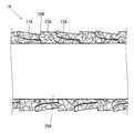
- FIG. 7 is a schematic sectional drawing which shows a part of 1A of wire harnesses with a nonwoven fabric exterior material which concerns on 2nd Embodiment.
- the proximal end portion of the first belt-like portion 11A and the proximal end portion of the second belt-like portion 13A are respectively continuous on both sides in the width direction of the intermediate portion 15A.
- the width of the first strip portion 11A and the width of the second strip portion 13A are substantially the same. For this reason, as shown in FIG. 7, in the winding operation, the entire first strip portion 11 ⁇ / b> A is overlapped with the second strip portion 13 ⁇ / b> A previously wound around the wire harness 20.
- the thickness of the intermediate portion 15A is larger than the thickness of the first strip portion 11A and the thickness of the second strip portion 13A.
- the thickness of the intermediate portion 15A is substantially the same as the sum of the thickness of the first strip portion 11A and the thickness of the second strip portion 13A.
- the thickness of the first strip portion 11A and the thickness of the second strip portion 13A are substantially the same.
- the thicknesses of the first strip portion 11A and the second strip portion 13A may be different.
- the convex-shaped part 31 and the concave-shaped part 33 are abbreviate
- the convex portion 31 may be provided in the first strip portion 11A, and the concave portion 33 may be provided in the second strip portion 13A.
- the second belt-like portion 13A is not connected to the lower end portion of the intermediate portion 15A.
- a slight gap is formed between the base end portion (the portion connected to the intermediate portion 15 ⁇ / b> A) of the second belt-like portion 13 ⁇ / b> A and the wire harness 20. Will occur.
- the first belt-like portion 11A is not connected to the upper end portion of the intermediate portion 15A, a concave portion is formed at the base end portion of the first belt-like portion 11A.
- the nonwoven fabric exterior material 10 which concerns on 1st Embodiment is a preferable form at the point of the uniformity of thickness.
- the thickness of the first strip portion 11A and the second strip portion 13A is smaller than the thickness of the intermediate portion 15A, the thickness of the overlapping portion of the first strip portion 11A and the second strip portion 13A is the intermediate portion 15A. Can be suppressed from becoming extremely large. Therefore, variation in the thickness of the nonwoven fabric exterior material 10A in the wound form can be reduced.
- tape winding may be performed near both ends of the nonwoven fabric exterior material 10 in the wound form.
- the first belt-like portion 11 is provided with a convex portion 31, and the second belt-like portion 13 is provided with a concave portion 33.
- a plurality of convex portions 31 may be provided in the first strip portion 11, and a plurality of concave portions 33 may be provided in the second strip portion 13 so as to correspond thereto.
- both the convex part 31 and the concave part 33 may be provided in the 1st strip
Landscapes
- Engineering & Computer Science (AREA)
- Architecture (AREA)
- Civil Engineering (AREA)
- Structural Engineering (AREA)
- Details Of Indoor Wiring (AREA)
- Insulated Conductors (AREA)
Abstract
ワイヤーハーネスに巻きつけられた形態における不織布外装材の厚さのばらつきを低減する技術を提供する。不織布外装材10は、当該不織外装材10の長手方向に延びる第1帯状部11と、長手方向に延びる第2帯状部13と、不織布外装材の幅方向一方側の部分151に第1帯状部11が連続しており、幅方向他方側の部分153に第2帯状部13が連続する中間部15とを備える。中間部15の厚さ(H1)は、第1帯状部11の厚さ(H2)及び第2帯状部13の厚さ(H3)よりも大きい。不織布外装材10をワイヤーハーネス20に巻きつける際には、第1帯状部11が、先に巻きつけられた第2帯状部13の表面に重ねられる。
Description
この発明は、ワイヤーハーネスに取り付けられる不織布外装材に関する。
ワイヤーハーネスを保護することを目的として、不織布外装材が取り付けられる場合がある。例えば、特許文献1には、帯状の不織材料を電線束に巻きつけて電線束を覆い、その巻きつけた形態の不織材料を加熱及び圧縮して成形する、電線保護構造部の製造方法が開示されている。
しかしながら、従来技術の場合、帯状の不織材料を、例えば幅寸法の半分ずらしつつ、重ねながら電線束に巻きつけられていた。このため、不織材料を巻きつけただけの形態では、不織材料を含めたワイヤーハーネスの太さにばらつきが発生してしまう(特に、特許文献1の第2図参照)。このため、電線束に巻きつけた形態の不織材料を加熱圧縮したとしても、巻きつけられた形態における不織材料の厚さがばらつくおそれがあった。このため、加圧圧縮されたとしても、不織材料の表面に凹凸が生じるおそれがあった。したがって、不織材料が、ワイヤーハーネスが配策された車体パネル等の他部材と繰り返し接触することによって、損傷しやすくなるおそれがあった。
そこで、本発明は、ワイヤーハーネスに巻きつけられた形態における不織布外装材の厚さのばらつきを低減する技術を提供することを目的とする。
上記の課題を解決するため、第1の態様は、ワイヤーハーネスに巻きつけられる不織布外装材であって、前記不織布外装材の長手方向に延びる第1帯状部と、前記不織布外装材の長手方向に延びる第2帯状部と、前記不織布外装材の幅方向一方側の端部に前記第1帯状部が連続しており、幅方向他方側の端部に前記第2帯状部が連続する中間部とを備え、前記中間部の厚さが、前記第1帯状部の厚さ及び前記第2帯状部の厚さよりも大きい。
また、第2の態様は、第1の態様に係る不織布外装材であって、前記第1帯状部の幅及び前記第2帯状部の幅が同一である。
また、第3の態様は、第1または第2の態様に係る不織布外装材であって、前記中間部における、前記第1帯状部の基端部が連続する前記幅方向一方側の端部、及び、前記第2帯状部の基端部が連続する前記幅方向他方側の端部の位置が、前記不織布外装材の厚さ方向において互いに相違する。
また、第4の態様は、第3の態様に係る不織布外装材であって、前記幅方向一方側の端部が前記中間部における前記厚さ方向の一方側の端部であり、前記幅方向他方側の端部が前記中間部における前記厚さ方向の他方側の端部である。
また、第5の態様は、第1から第4の態様のいずれか1態様に係る不織布外装材であって、前記第1帯状部及び前記第2帯状部を重ねた際の厚さが、前記中間部の厚さと同一である。
また、第6の態様は、第1から第5の態様のいずれか1態様に係る不織布外装材であって、前記第1帯状部の一方側面に凸状部が形成されており、前記第2帯状部の他方側面に前記凸状部が進入可能な大きさの凹状部が形成されている。
また、第7の態様は、第6の態様に係る不織布外装材であって、前記凸状部及び前記凹状部が、前記不織布外装材の長手方向に延びる。
また、第8の態様は、ワイヤーハーネスに帯状の不織布外装材が巻きつけられている形態の不織布外装材付ワイヤーハーネスであって、前記不織布外装材は、前記不織布外装材の長手方向に延びる第1帯状部と、前記不織布外装材の長手方向に延びる第2帯状部と、前記不織布外装材の幅方向一方側部分に前記第1帯状部が連続しており、幅方向他方側部分に前記第2帯状部が連続する中間部とを含み、前記中間部の厚さが、前記第1帯状部の厚さ及び前記第2帯状部の厚さよりも大きい。
また、第9の態様は、ワイヤーハーネスに帯状の不織布外装材が巻きつけられている形態の不織布外装材付ワイヤーハーネスの製造方法であって、(a)不織布外装材の長手方向に延びる第1帯状部と、前記不織布外装材の長手方向に延びる第2帯状部と、前記不織布外装材の幅方向一方側部分に前記第1帯状部が連続しており、幅方向他方側部分に前記第2帯状部が連続する中間部と、を備え、前記中間部の厚さが、前記第1帯状部の厚さ及び前記第2帯状部の厚さよりも大きい、不織布外装材を準備する工程と、(b)前記第1帯状部が、先にワイヤーハーネスに巻きつけられた前記第2帯状部の表面に重なるようにして、前記不織布外装材を前記ワイヤーハーネスに巻きつける工程と、を含む。
第1から第9の態様によると、第1帯状部及び第2帯状部が重なるように不織布外装材をワイヤーハーネスに巻きつけた際に、その重なり部分の厚さが、中間部の厚さよりも極端に大きくなることを抑制できる。このため、巻きつけられた形態における不織布外装材の厚さのばらつきを低減できる。
第2の態様によると、第1帯状部及び第2帯状部の幅を同一とすることによって、第1帯状部をその幅方向全体にわたって、第2帯状部に重ねることができる。
また、第3の態様によると、第1帯状部の基端部及び第2帯状部の基端部のそれぞれが、中間部に連続する位置が厚さ方向に異なるため、第1帯状部及び第2帯状部が重ねた際に、第1帯状部または第2帯状部がよれることを低減できる。このため、巻きつけた形態における不織布外装材の厚さのばらつきを低減できる。
また、第4の態様に係る不織布外装材によると、第1帯状部及び第2帯状部を重ねた際における、第1帯状部または第2帯状部のよれを効果的に抑制できる。
また、第5の態様によると、巻きつけた形態の不織布外装材において、第1帯状部及び第2帯状部の重なり部分の厚さと、中間部の厚さとを同一にできる。このため、巻きつけた形態の不織布外装材における厚さのばらつきを効果的に低減できる。
また、第6の態様によると、第1帯状部の凸状部を第2帯状部の凹状部に挿入しつつ、ワイヤーハーネスに不織布外装材を巻きつけることによって、第1帯状部及び第2帯状部がずれることを低減できる。
また、第7の態様によると、第1帯状部及び第2帯状部がずれることを効果的に低減できる。
以下、添付の図面を参照しながら、本発明の実施形態について説明する。なお、この実施形態に記載されている構成要素はあくまでも例示であり、本発明の範囲をそれらのみに限定する趣旨のものではない。また、図面においては、理解容易のため、必要に応じて各部の寸法や数が誇張または簡略化して図示されている場合がある。
<1. 第1実施形態>
図1は、第1実施形態に係る不織布外装材10を示す概略斜視図である。図2は、第1実施形態に係る不織布外装材10に係る概略正面図である。図3は、第1実施形態に係る不織布外装材10がワイヤーハーネス20に巻きつけられる前の様子を示す概略斜視図である。
図1は、第1実施形態に係る不織布外装材10を示す概略斜視図である。図2は、第1実施形態に係る不織布外装材10に係る概略正面図である。図3は、第1実施形態に係る不織布外装材10がワイヤーハーネス20に巻きつけられる前の様子を示す概略斜視図である。
また、図4は、第1実施形態に係る不織布外装材10がワイヤーハーネス20に巻きつけられる様子を示す概略斜視図である。図5は、第1実施形態に係る不織布外装材付ワイヤーハーネス1の一部を示す概略断面図である。
以下の説明では、図1に示されるように、矢符AR1で示す不織布外装材10の長手方向を、単に「長手方向」と称する。また、矢符AR2で示す不織布外装材10の幅方向を、単に「幅方向」と称する。当該幅方向は、上記長手方向に直交する方向である。また、矢符AR3で示す不織布外装材10の厚さ方向を、単に「厚さ方向」と称する。当該厚さ方向は、上記長手方向及び上記幅方向の双方に直交する方向である。さらに、ワイヤーハーネス20に巻きつけた際に、不織布外装材10における、ワイヤーハーネス20の外周面に対向する表面の側を、「厚さ方向上側」と称し、その反対側を「厚さ方向下側」と称する。
不織布外装材10は、不織布を加熱圧縮することによって形成される部材である。ここで、加熱圧縮とは、加工対象である熱可塑性材料を金型間に挟み込み、金型を加熱した状態で圧力を加えることによって、熱可塑性樹脂を成形加工することをいう。なお、加熱圧縮するための金型のセットは、2つの金型で構成されるものに限定されず、例えば3つ以上に分割された金型で構成されていてもよい。
熱可塑性材料とは、加熱されることによって部分的または全体的に溶融または軟化し、冷却されることによって硬化する材料である。そして、この熱可塑性材料は、加熱されて溶融または軟化した状態で成形加工されて冷却されることによって、成形された所定の形状を維持する。ここでは、熱可塑性材料として不織材料が用いられる。
不織材料としては、加熱工程を経て部分的または全体的に溶融または軟化し、その後冷却工程を経て硬化するものを用いるとよい。不織材料として、基本繊維と接着樹脂(バインダとも称する。)とを含むものを用いることができる。接着樹脂は、基本繊維の融点よりも低い融点を有する。加熱工程にて、不織材料を基本繊維より低くかつ接着樹脂の融点よりも高い温度に加熱することによって、接着樹脂が溶融され、基本繊維間に浸透する。その後、冷却工程にて不織材料の温度が低下すると、接着樹脂が凝固する。これによって、不織材料を加熱時に成形した形状に維持させることができる。
不織材料の基本繊維としては、接着樹脂の融点で遷移状態を保つことが可能であれば、樹脂繊維またはその他の繊維を採用できる。また、接着樹脂としては、基本繊維の融点よりも低い融点の熱可塑性樹脂を採用できる。基本繊維及び接着樹脂の組み合せとしては、一例として、基本繊維をPET(ポリエチレンテレフタレート)の樹脂繊維とされ、接着樹脂をPETとPEI(ポリエチレンイソフタレート)との共重合樹脂とされる。
もっとも、不織布外装材10は、加熱圧縮することによって成形された成形品であるが、その長手方向において、作業者が手作業で丸めることができる程度の柔軟性を備えている。
図1及び図2に示すように、不織布外装材10は、第1帯状部11、第2帯状部13及び中間部15を備えている。
第1帯状部11及び第2帯状部13は、不織布外装材10の長手方向に沿って延びる部分であり、かつ、幅方向に平行な部分を有している。第1帯状部11及び第2帯状部13は、間に中間部15を介して連結されている。また、第1帯状部11の幅(幅方向の大きさ)は、第2帯状部13の幅と略同一とされている。
詳細には、第1帯状部11の幅方向基端側の部分は、中間部15の幅方向一方側の部分151に連続している。また、第2帯状部13の幅方向基端側の部分は、中間部15の幅方向他方側の部分153に連続している。
第1帯状部11の基端部、及び、基端部及び第2帯状部の基端部のそれぞれが、中間部15に連続する位置は、厚さ方向において異なっている。本例では、図1または図2に示すように、第1帯状部11が連続する幅方向一方側の部分151は、中間部15の厚さ方向下側の端部(厚さ方向一方側の端部)となっている。第1帯状部11の下面及び中間部15の下面は、少なくともその接続部分において面一となっている。第2帯状部13が連続する幅方向他方側の部分153は、中間部15の厚さ方向上側の端部(厚さ方向他方側の端部)となっている。第2帯状部13の上面及び中間部15の上面は、少なくともその接続部分において面一となっている。
図1及び図2に示すように、第1帯状部11における幅方向中央部に、長手方向に渡って厚さ方向上側に突出する凸状部31が設けられている。凸状部31は、その横断面(長手方向と直角をなす平面に沿って切った切り口)が略半円状とされている。また、第2帯状部13における幅方向中央部に、長手方向に渡って厚さ方向上側に凹む凹状部33が設けられている。凹状部33は、横断面視において、凸状部31に対応する略半円形状を有する。ここで「対応する」とは、少なくとも凹状部33が凸状部31を差し込むことが可能な大きさを有することをいう。
第1帯状部11及び第2帯状部13が重なるように不織布外装材10をワイヤーハーネス20に巻きつける際(図4参照)、図5に示すように、凸状部31が凹状部33に差し込まれる。
なお、凹状部33の幅(幅方向の大きさ)は、必ずしも凸状部31の幅よりも大きくする必要はない。例えば、凹状部33の幅を凸状部31の幅よりも小さくすることによって、凹状部33に差し込まれた凸状部31を抜け難くすることができる。
また、凸状部31及び凹状部33の形状は、必ずしも横断面視において略半円形状である必要はない。一例として、楕円形状、角形状(矩形状を含む。)、角丸の角形状、またはこれらを組み合わせた形状であってもよい。また、凸状部31及び凹状部33の横断面視における形状は、必ずしも相似である必要はない。
また、凸状部31は、必ずしも長手方向に平行に延びている必要はない。一例として、凸状部31が長手方向の成分と幅方向の成分を持つ合成方向に延びていてもよい。また、凸状部を長手方向に渡って分散して設けられた複数のピン状の突起物(すなわち、厚さ方向上側に向かって延びる細長い突起物)としてもよい。ただし、ワイヤーハーネス20の延びる方向に不織布外装材10がずれることを抑制する点では、本実施形態のように、凸状部が長手方向に延びる形態である方が好ましい。いずれの場合であっても、凸状部(複数の突起物を含む。)の位置、大きさ、形状に対応させて、凹状部(複数の突起物に対応する複数の凹状部を含む。)を設けるとよい。
図1に示すように、第1帯状部11及び第2帯状部13の両端付近における厚さ方向上側の表面には、接着材料40がそれぞれ付着されている。接着材料としては、両面粘着テープが好適である。
巻きつけ作業においては、図3に示すように、不織布外装材10の一端部が、接着材料40,40を介して、ワイヤーハーネス20に接着される。そして、図4に示すように、不織布外装材10の他の部分がワイヤーハーネス20に巻きつけられる。
不織布外装材10をワイヤーハーネス20に巻きつける際には、これから巻きつけようとする第1帯状部11の部分が、先に巻きつけられている第2帯状部13の上側に重ねられる。このとき、図5に示すように、第1帯状部11の先端を、先に巻きつけられている中間部15の幅方向他方側の側面(第2帯状部13の基端部が連続する面)に接触させる。これによって、中間部15と第1帯状部11との間に隙間ができることを抑制できる。
また、第1帯状部11を第2帯状部13に重ねる際には、上述したように、第1帯状部11の凸状部31が、第2帯状部13の凹状部33に差し込まれる。これによって、第1帯状部11がワイヤーハーネス20の延びる方向にずれることを抑制できる。したがって、巻きつけられた形態の不織布外装材10に隙間ができることを抑制できる。よって、ワイヤーハーネス20が外部に露出することを抑制できる。
また、不織布外装材10の長さ、または、巻きつける際のらせんピッチを調整することによって、ワイヤーハーネス20における不織布外装材10を取り付けるべき部分の長さ、または、ワイヤーハーネス20の径に対応するよう、不織布外装材10を取り付けることができる。
巻きつけが完了すると、不織布外装材10の他端部が、接着材料40を介してワイヤーハーネス20に接着される。ただし、第2帯状部13の接着材料40が直接ワイヤーハーネス20に接着されるのに対して、第1帯状部11の接着材料40は、当該部分が重ねられる第2帯状部13の表面に接着される。これによって、図4に示すように、不織布外装材付ワイヤーハーネス1が製造される。
第1帯状部11及び第2帯状部13を成形する際の金型間の隙間が、幅方向に関して均一とされる。これによって、図2に示すように、第1帯状部11における凸状部31以外の部分の厚さ、及び、第2帯状部13における凹状部33以外の部分の厚さは、それぞれ、幅方向に渡って均一とされている。中間部15についても、幅方向に関して厚さは均一とされている。
中間部15の厚さ(H1)は、第1帯状部11の凸状部31を除く部分の厚さ(H2)及び第2帯状部13の凹状部33を除く部分の厚さ(H3)よりも大きい(H1>H2,H1>H3)。これによって、第1帯状部11及び第2帯状部13を重ねた際に、その厚さが非重ね部分である中間部15の厚さよりも極端に大きくなることを抑制できる。
本例では、中間部15の厚さ(H1)は、第1帯状部11の厚さ(H2)及び第2帯状部13の厚さ(H3)の合計値(=H2+H3)と略同一されている。このため、図5に示すように、巻きつけられた形態の不織布外装材10においては、第1帯状部11及び第2帯状部13の重なり部分の厚さと、中間部15の厚さとが、略同一となる。すなわち、巻きつけられた形態における不織布外装材10の厚さが、ワイヤーハーネス20の延びる方向において、略均一となっている。
また、図2に示すように、本例では、第1帯状部11の厚さ(H2)と、第2帯状部13の厚さ(H3)とを、同一としている。もっとも、これらの厚さは互いに相違していてもよい。一例として、どちらか一方が、他方よりも肉厚に形成されていてもよい。
また、巻きつけられた形態における不織布外装材10の厚さのばらつきを抑制するため、図5に示すように、凹状部33が、凸状部31の略完全を挿入できる大きさを有していることが望ましい。これによって、第1帯状部11及び第2帯状部13における、互いに平行な部分同士を、隙間無く接触させることができる。このため、巻きつけられた形態における不織布外装材10の厚さを均一化できる。
<2. 第2実施形態>
図6は、第2実施形態に係る不織布外装材10Aを示す概略斜視図である。図7は、第2実施形態に係る不織布外装材付ワイヤーハーネス1Aの一部を示す概略断面図である。
図6は、第2実施形態に係る不織布外装材10Aを示す概略斜視図である。図7は、第2実施形態に係る不織布外装材付ワイヤーハーネス1Aの一部を示す概略断面図である。
本実施形態に係る不織布外装材10Aは、第1帯状部11A、第2帯状部13A及び中間部15Aを備えている。第1帯状部11Aの基端部及び第2帯状部13Aの基端部は、中間部15Aの幅方向両側にそれぞれ連続している。
第1帯状部11Aの幅及び第2帯状部13Aの幅は略同一とされている。このため、図7に示すように、巻きつけ作業においては、第1帯状部11Aの全体が、先にワイヤーハーネス20に巻かれている第2帯状部13Aと重ねられる。
また、図6に示すように、中間部15Aの厚さは、第1帯状部11Aの厚さ及び第2帯状部13Aの厚さよりも大きい。本例では、中間部15Aの厚さは、第1帯状部11Aの厚さ及び第2帯状部13Aの厚さの合計と略同一とされている。また、第1帯状部11Aの厚さ及び第2帯状部13Aの厚さは、略同一としている。ただし、第1帯状部11A及び第2帯状部13Aの厚さは、相違していてもよい。
また、本実施形態に係る不織布外装材10Aには、凸状部31,凹状部33が省略されているが、当然に設けられていてもよい。例えば、第1帯状部11Aに凸状部31を設け、第2帯状部13Aに凹状部33を設ければよい。
不織布外装材10Aでは、第2帯状部13Aが、中間部15Aの下端部に接続されていない。このため、図7に示すように、巻きつけられた形態における不織布外装材10Aでは、第2帯状部13Aの基端部(中間部15Aにつながる部分)及びワイヤーハーネス20の間に、若干の隙間が発生してしまう。同様に、第1帯状部11Aが、中間部15Aの上端部に接続されていないため、第1帯状部11Aの基端部において、凹状部を形成してしまう。このため、第1実施形態に係る不織布外装材10の方が、厚さの均一性の点では好ましい形態である。しかしながら、第1帯状部11A及び第2帯状部13Aの厚さが、中間部15Aの厚さよりも小さいため、第1帯状部11A及び第2帯状部13Aの重なり部分の厚さが、中間部15Aよりも極端に大きくなることを抑制できる。したがって、巻きつけられた形態における不織布外装材10Aの厚さのばらつきを低減できる。
<3. 変形例>
以上、実施形態について説明してきたが、本発明は上記のようなものに限定されるものではなく、様々な変形が可能である。
以上、実施形態について説明してきたが、本発明は上記のようなものに限定されるものではなく、様々な変形が可能である。
例えば、巻きつけられた形態における不織布外装材10,10Aの一部に、テープ巻きを施すことによって、不織布外装材10,10Aをワイヤーハーネス20に固定してもよい。一例として、巻きつけられた形態における不織布外装材10の両端付近に、テープ巻きを施してもよい。
また、巻きつけられた形態の不織布外装材10,10Aに対して、加熱圧縮を行うようにしてもよい。
また、不織布外装材10においては、第1帯状部11に凸状部31が設けられ、第2帯状部13に凹状部33が設けられている。しかしながら、第1帯状部11に複数の凸状部31を設け、これに対応するよう第2帯状部13に複数の凹状部33を設けてもよい。あるいは、凸状部31及び凹状部33の双方を第1帯状部11に設け、これに対応させて、第2帯状部に凹状部33及び凸状部31を設けてもよい。
この発明は詳細に説明されたが、上記の説明は、すべての局面において、例示であって、この発明がそれに限定されるものではない。例示されていない無数の変形例が、この発明の範囲から外れることなく想定され得るものと解される。また、上記各実施形態及び各変形例で説明した各構成は、相互に矛盾しない限り適宜組み合わせたり、省略したりすることができる。
1,1A 不織布外装材付ワイヤーハーネス
10,10A 不織布外装材
11,11A 第1帯状部
13,13A 第2帯状部
15,15A 中間部
20 ワイヤーハーネス
31 凸状部
33 凹状部
151 部分(厚さ方向一方側の端部)
153 部分(厚さ方向他方側の端部)
AR1 矢符(長手方向)
AR2 矢符(幅方向)
AR3 矢符(厚さ方向)
10,10A 不織布外装材
11,11A 第1帯状部
13,13A 第2帯状部
15,15A 中間部
20 ワイヤーハーネス
31 凸状部
33 凹状部
151 部分(厚さ方向一方側の端部)
153 部分(厚さ方向他方側の端部)
AR1 矢符(長手方向)
AR2 矢符(幅方向)
AR3 矢符(厚さ方向)
Claims (9)
- ワイヤーハーネスに巻きつけられる不織布外装材であって、
前記不織布外装材の長手方向に延びる第1帯状部と、
前記不織布外装材の長手方向に延びる第2帯状部と、
前記不織布外装材の幅方向一方側の端部に前記第1帯状部が連続しており、幅方向他方側の端部に前記第2帯状部が連続する中間部と、
を備え、
前記中間部の厚さが、前記第1帯状部の厚さ及び前記第2帯状部の厚さよりも大きい、不織布外装材。 - 請求項1に記載の不織布外装材であって、
前記第1帯状部の幅及び前記第2帯状部の幅が同一である、不織布外装材。 - 請求項1または請求項2に記載の不織布外装材であって、
前記中間部における、前記第1帯状部の基端部が連続する前記幅方向一方側の端部、及び、前記第2帯状部の基端部が連続する前記幅方向他方側の端部の位置が、前記不織布外装材の厚さ方向において互いに相違する、不織布外装材。 - 請求項3に記載の不織布外装材であって、
前記幅方向一方側の端部が前記中間部における前記厚さ方向の一方側の端部であり、前記幅方向他方側の端部が前記中間部における前記厚さ方向の他方側の端部である、不織布外装材。 - 請求項1から請求項4のいずれか1項に記載の不織布外装材であって、
前記第1帯状部及び前記第2帯状部を重ねた際の厚さが、前記中間部の厚さと同一である、不織布外装材。 - 請求項1から請求項5のいずれか1項に記載の不織布外装材であって、
前記第1帯状部の一方側面に凸状部が形成されており、前記第2帯状部の他方側面に前記凸状部が進入可能な大きさの凹状部が形成されている、不織布外装材。 - 請求項6に記載の不織布外装材であって、
前記凸状部及び前記凹状部が、前記不織布外装材の長手方向に延びる、不織布外装材。 - ワイヤーハーネスに帯状の不織布外装材が巻きつけられている形態の不織布外装材付ワイヤーハーネスであって、
前記不織布外装材は、
前記不織布外装材の長手方向に延びる第1帯状部と、
前記不織布外装材の長手方向に延びる第2帯状部と、
前記不織布外装材の幅方向一方側部分に前記第1帯状部が連続しており、幅方向他方側部分に前記第2帯状部が連続する中間部と、
を備え、
前記中間部の厚さが、前記第1帯状部の厚さ及び前記第2帯状部の厚さよりも大きい、不織布外装材付ワイヤーハーネス。 - ワイヤーハーネスに帯状の不織布外装材が巻きつけられている形態の不織布外装材付ワイヤーハーネスの製造方法であって、
(a) 前記不織布外装材の長手方向に延びる第1帯状部と、前記不織布外装材の長手方向に延びる第2帯状部と、前記不織布外装材の幅方向一方側部分に前記第1帯状部が連続しており、幅方向他方側部分に前記第2帯状部が連続する中間部と、を備え、前記中間部の厚さが、前記第1帯状部の厚さ及び前記第2帯状部の厚さよりも大きい、不織布外装材を準備する工程と、
(b) 前記第1帯状部が、先にワイヤーハーネスに巻きつけられた前記第2帯状部の表面に重なるようにして、前記不織布外装材を前記ワイヤーハーネスに巻きつける工程と、
を含む、不織布外装材付ワイヤーハーネスの製造方法。
Applications Claiming Priority (2)
| Application Number | Priority Date | Filing Date | Title |
|---|---|---|---|
| JP2015-012097 | 2015-01-26 | ||
| JP2015012097A JP2016140131A (ja) | 2015-01-26 | 2015-01-26 | 不織布外装材、不織布外装材付ワイヤーハーネス、及び、不織布外装材付ワイヤーハーネスの製造方法 |
Publications (1)
| Publication Number | Publication Date |
|---|---|
| WO2016121504A1 true WO2016121504A1 (ja) | 2016-08-04 |
Family
ID=56543123
Family Applications (1)
| Application Number | Title | Priority Date | Filing Date |
|---|---|---|---|
| PCT/JP2016/050924 Ceased WO2016121504A1 (ja) | 2015-01-26 | 2016-01-14 | 不織布外装材、不織布外装材付ワイヤーハーネス、及び、不織布外装材付ワイヤーハーネスの製造方法 |
Country Status (2)
| Country | Link |
|---|---|
| JP (1) | JP2016140131A (ja) |
| WO (1) | WO2016121504A1 (ja) |
Citations (3)
| Publication number | Priority date | Publication date | Assignee | Title |
|---|---|---|---|---|
| JPH097429A (ja) * | 1995-06-14 | 1997-01-10 | Sumitomo Wiring Syst Ltd | 静電・電磁遮蔽機能付ケーブルとその配線方法並びにケーブル用静電・電磁遮蔽テープ |
| JP2012029499A (ja) * | 2010-07-26 | 2012-02-09 | Chugoku Electric Power Co Inc:The | 電線防護具及び電線防護具の取り付け方法 |
| JP2012199079A (ja) * | 2011-03-22 | 2012-10-18 | Auto Network Gijutsu Kenkyusho:Kk | 保護部材付電線及び保護部材付電線の製造方法 |
-
2015
- 2015-01-26 JP JP2015012097A patent/JP2016140131A/ja active Pending
-
2016
- 2016-01-14 WO PCT/JP2016/050924 patent/WO2016121504A1/ja not_active Ceased
Patent Citations (3)
| Publication number | Priority date | Publication date | Assignee | Title |
|---|---|---|---|---|
| JPH097429A (ja) * | 1995-06-14 | 1997-01-10 | Sumitomo Wiring Syst Ltd | 静電・電磁遮蔽機能付ケーブルとその配線方法並びにケーブル用静電・電磁遮蔽テープ |
| JP2012029499A (ja) * | 2010-07-26 | 2012-02-09 | Chugoku Electric Power Co Inc:The | 電線防護具及び電線防護具の取り付け方法 |
| JP2012199079A (ja) * | 2011-03-22 | 2012-10-18 | Auto Network Gijutsu Kenkyusho:Kk | 保護部材付電線及び保護部材付電線の製造方法 |
Also Published As
| Publication number | Publication date |
|---|---|
| JP2016140131A (ja) | 2016-08-04 |
Similar Documents
| Publication | Publication Date | Title |
|---|---|---|
| JP5891868B2 (ja) | ワイヤーハーネスの製造方法及びワイヤーハーネス | |
| US20130056240A1 (en) | Wire protection member | |
| CN104009424A (zh) | 线束以及线束的制造方法 | |
| CN103890863B (zh) | 线束及线束的制造方法 | |
| CN104160570B (zh) | 线束以及线束的制造方法 | |
| CN103890861B (zh) | 线束以及线束的制造方法 | |
| US20130161092A1 (en) | Wire harness | |
| US9490049B2 (en) | Wire harness, method for manufacturing wire harness, and protective member | |
| WO2014050221A1 (ja) | ワイヤーハーネス、ワイヤーハーネスの製造方法及び保護部材 | |
| US9349509B2 (en) | Wire harness and manufacturing method for wire harness | |
| CN103797547A (zh) | 线束及其制造方法 | |
| US9358937B2 (en) | Wire harness with sheathing member and path regulators | |
| WO2016158455A1 (ja) | 外装ワイヤーハーネス | |
| US10886038B2 (en) | Exterior member-equipped wire | |
| CN104662756A (zh) | 线束、线束的制造方法以及保护部件 | |
| WO2016121504A1 (ja) | 不織布外装材、不織布外装材付ワイヤーハーネス、及び、不織布外装材付ワイヤーハーネスの製造方法 | |
| US20140131093A1 (en) | Wire harness | |
| WO2013132570A1 (ja) | 電線保護構造部の製造方法及び電線保護構造部 | |
| JP5541083B2 (ja) | 電線保護構造部の製造方法及び電線保護構造部 | |
| WO2014129011A1 (ja) | ワイヤーハーネス及びワイヤーハーネスの製造方法 | |
| JP5803735B2 (ja) | ワイヤーハーネス及びワイヤーハーネスの製造方法 | |
| JP7092209B2 (ja) | 配線部材 | |
| JP2013183609A (ja) | ワイヤーハーネス及びその製造方法 | |
| WO2017183520A1 (ja) | 外装部材付電線 | |
| CN104662755A (zh) | 线束 |
Legal Events
| Date | Code | Title | Description |
|---|---|---|---|
| 121 | Ep: the epo has been informed by wipo that ep was designated in this application |
Ref document number: 16743108 Country of ref document: EP Kind code of ref document: A1 |
|
| NENP | Non-entry into the national phase |
Ref country code: DE |
|
| 122 | Ep: pct application non-entry in european phase |
Ref document number: 16743108 Country of ref document: EP Kind code of ref document: A1 |