WO2016121430A1 - 色変換テーブル作成装置、色変換テーブル作成方法、及び色変換テーブル作成プログラム - Google Patents
色変換テーブル作成装置、色変換テーブル作成方法、及び色変換テーブル作成プログラム Download PDFInfo
- Publication number
- WO2016121430A1 WO2016121430A1 PCT/JP2016/050225 JP2016050225W WO2016121430A1 WO 2016121430 A1 WO2016121430 A1 WO 2016121430A1 JP 2016050225 W JP2016050225 W JP 2016050225W WO 2016121430 A1 WO2016121430 A1 WO 2016121430A1
- Authority
- WO
- WIPO (PCT)
- Prior art keywords
- image data
- resolution
- color
- color conversion
- unit
- Prior art date
- Legal status (The legal status is an assumption and is not a legal conclusion. Google has not performed a legal analysis and makes no representation as to the accuracy of the status listed.)
- Ceased
Links
Images


Classifications
-
- B—PERFORMING OPERATIONS; TRANSPORTING
- B41—PRINTING; LINING MACHINES; TYPEWRITERS; STAMPS
- B41J—TYPEWRITERS; SELECTIVE PRINTING MECHANISMS, i.e. MECHANISMS PRINTING OTHERWISE THAN FROM A FORME; CORRECTION OF TYPOGRAPHICAL ERRORS
- B41J2/00—Typewriters or selective printing mechanisms characterised by the printing or marking process for which they are designed
- B41J2/525—Arrangement for multi-colour printing, not covered by group B41J2/21, e.g. applicable to two or more kinds of printing or marking process
-
- G—PHYSICS
- G06—COMPUTING OR CALCULATING; COUNTING
- G06T—IMAGE DATA PROCESSING OR GENERATION, IN GENERAL
- G06T1/00—General purpose image data processing
-
- H—ELECTRICITY
- H04—ELECTRIC COMMUNICATION TECHNIQUE
- H04N—PICTORIAL COMMUNICATION, e.g. TELEVISION
- H04N1/00—Scanning, transmission or reproduction of documents or the like, e.g. facsimile transmission; Details thereof
- H04N1/46—Colour picture communication systems
-
- H—ELECTRICITY
- H04—ELECTRIC COMMUNICATION TECHNIQUE
- H04N—PICTORIAL COMMUNICATION, e.g. TELEVISION
- H04N1/00—Scanning, transmission or reproduction of documents or the like, e.g. facsimile transmission; Details thereof
- H04N1/46—Colour picture communication systems
- H04N1/56—Processing of colour picture signals
- H04N1/60—Colour correction or control
Definitions
- the present invention relates to a color conversion table creation device, a color conversion table creation method, and a color conversion table creation program, and more particularly to a color conversion technique for image data applied to color reproduction by a printing device.
- a profile creation chart composed of a plurality of color patches is printed, the printed profile creation chart is read, and the profile is read from the read data of the profile creation chart.
- the method of creating is generally known.
- Patent Documents 1 and 2 describe a technique for realizing color reproduction without creating a profile creation chart.
- Patent Document 1 discloses an image reading apparatus capable of reproducing a color close to an original by a printing apparatus without excessively compressing a color gamut used in the original read by a scanner.
- the image reading apparatus of Patent Document 1 creates color gamut information of a document from the read document, and outputs an image file to which the color gamut information is added.
- the color gamut information includes maximum brightness information, minimum brightness information, saturation information for each hue, and the like.
- Patent Document 1 when an image file to which color gamut information is added is re-output by a printer as a printing apparatus, the color gamut information is compared with a printer color gamut that is a color gamut reproducible by the printer, A color conversion coefficient is selected.
- Patent Document 2 discloses an image processing apparatus that can adjust the color tones of two printed materials without using a color chart.
- a reference printed matter output by a first image output device serving as a reference printer and a user printed matter output by a second image output device serving as a user printer are read by a scanner, A color tone conversion parameter is obtained from the correspondence between the color component values, and the color tone equivalent to the color tone of the reference printed matter is reproduced by correcting the output image of the second image output device with the obtained color tone conversion parameter.
- Patent Document 1 re-output by a printer is premised on a read image read by a scanner or an image file of a read image.
- the read image lacks definition due to the influence of blur at the time of reading depending on the reading resolution of the scanner, it is difficult to obtain a printed matter that reproduces a high-definition original image.
- Patent Document 2 it is necessary to print a user print and read it by a scanner separately from the reference print, which is troublesome.
- the technique described in Patent Document 2 obtains a color tone conversion parameter for each RGB color component read by the scanner, and performs color correction by one-dimensional conversion for each RGB color component using the color tone conversion parameter for each color component. Is what you do.
- Such a conventional method is considered to be sufficient for correcting a color difference of about the individual difference of the printer device.
- the first image output device as the reference printer that outputs the reference printed matter and the first printer as the user printer.
- the degree of freedom of color correction is not sufficient, and the color correction accuracy may be lowered.
- RGB is a notation method that collectively represents red, green, and yellow.
- red may be represented by R, green by G, and yellow by Y.
- the present invention has been made in view of such circumstances, and a color conversion table creation device, a color conversion table creation method, and a color conversion method capable of achieving both high-definition image reproduction and reliable color reproduction. It is an object to provide a conversion table creation program.
- the color conversion table creation device reads target printed matter and printed matter printed by the printing device with a first resolution, and is target printed matter read image data representing a read image of the target printed matter, and has a first resolution.
- An image reading unit that acquires target printed material read image data having a first resolution and printed product read image data representing a read image of the printed product, and a device-dependent color space obtained from the image reading unit.
- the document image data representing the document image having the second resolution which is the document image data represented by the signal value, is different from the resolution of the print image data having the same resolution as that of the document image data, or the resolution of the document image data.
- a second color conversion unit that converts to print image data having resolution, and a signal value of the first color space obtained by reading the printed matter printed by the printing apparatus according to the print image data in the image reading unit. Processing for associating the positional relationship between the printed material read image data and the original image data, and the target printed material read image data and the original image data represented by the signal value of the first color space obtained by reading the target printed material in the image reading unit.
- the image association unit or the first color conversion unit that performs processing for associating the positional relationship with Processing for associating the positional relationship between the printed material read chromaticity value image data and the document image data obtained by converting the signal value of the product read image data into the chromaticity value of the second color space, and the first color conversion unit
- An image association unit that performs processing for associating the positional relationship between the target printed material read chromaticity value image data obtained by converting the signal value of the target printed material read image data into the chromaticity value in the second color space and the document image data;
- a third resolution less than the first resolution is obtained from the target printed material read chromaticity value image data in which the positional relationship with the document image data is associated by the resolution image creation unit or the image association unit.
- a first low-resolution image creating unit that creates low-resolution target printed matter read chromaticity value image data, and a second that creates low-resolution original image data having a fourth resolution less than the second resolution from the original image data.
- Low resolution image creation unit and low resolution printed matter read image data having a third resolution lower than the first resolution from the printed matter read image data in which the positional relationship with the original image data is associated by the image association unit From the printed material read chromaticity value image data in which the positional relationship with the document image data is associated by the third low-resolution image creation unit or the image association unit, the low resolution having a third resolution less than the first resolution
- the third low-resolution image creation unit that creates the resolution printed material read chromaticity value image data, the signal value of the document image data, the image association unit, and the first color conversion unit First color information correspondence relationship between the chromaticity value of the target printed matter and the chromaticity value of the printed matter obtained through the processing of the image association unit and the first color conversion unit, and low
- the first aspect it is possible to achieve both highly reliable color reproduction and high-definition image reproduction.
- the color conversion table is created using color information of different resolutions, colors can be matched on average from low resolution color information, and colors can be matched with high accuracy using high resolution color information.
- the color conversion table creation unit includes a first color information correspondence creation unit that creates a first color information correspondence relationship, From the second color information correspondence creation unit for creating the color information correspondence relationship, the first color information correspondence relationship, and the second color information correspondence relationship, the first color information correspondence relationship, And a third color information correspondence relationship representing a correspondence relationship between the signal value of the document image data common to the correspondence relationship between the second color information, the chromaticity value of the target printed matter, and the chromaticity value of the printed matter.
- a color conversion data creation unit including a third color information correspondence creation unit may be provided.
- the first inter-color information correspondence creation unit is subjected to processing of the document image data, the image association unit, and the first color conversion unit.
- Correspondence relationship with the target chromaticity value that is the chromaticity value of the target printed matter to be obtained, and printing that is the chromaticity value of the printed matter obtained through the processing of the document image data and the image associating unit and the first color converting unit From the correspondence relationship with the chromaticity value, the first color information correspondence relationship can be created using the target chromaticity value and the printing chromaticity value that match the signal values of the document image data.
- the second color information correspondence creation unit includes a low resolution document image data and an image association unit, a first low resolution image creation unit, And a correspondence relationship with a low resolution target chromaticity value that is a chromaticity value of a target printed matter obtained through the processing of the first color conversion unit, and document image data and an image association unit, a third low resolution image creation unit And the target chromaticity value that matches the signal value of the document image data and the low resolution target from the correspondence relationship with the low resolution printing chromaticity value that is the chromaticity value of the printed matter obtained through the processing of the first color conversion unit
- the second color information correspondence can be created from the chromaticity value and the printing chromaticity value that matches the signal value of the document image data and the low resolution printing chromaticity value.
- the third color information correspondence creation unit includes a first color information correspondence and a second color information correspondence.
- a configuration in which a third color information correspondence relationship is created by using the target chromaticity value and the print chromaticity value in the first color information correspondence relationship for the signal values of the document image data common to the correspondence relationship. Can do.
- the third color information correspondence creation unit includes a first color information correspondence relationship and a second color information correspondence For the signal value of the document image data common to the correspondence relationship, the average value of the target chromaticity value in the first color information correspondence relationship and the target chromaticity value in the second color information correspondence relationship, and the first color
- the third color information correspondence can be created using the average value of the print chromaticity values in the information correspondence and the print chromaticity values in the second color information correspondence.
- the color conversion table creation device reads target printed matter and printed matter printed by the printing device with a first resolution, and is target printed matter read image data representing a read image of the target printed matter, and the first resolution.
- a fourth low-resolution image creation unit that creates an intermediate-resolution document image data representing a document image having a sixth resolution less than the second resolution from the image data; and a fourth lower-resolution image creation unit that creates less than the first resolution from the target printed matter read image data 5th intermediate resolution target printed matter read image data having a resolution of 5 or a fifth solution less than the first resolution is generated from the printed matter read image data.
- a fifth low-resolution image creation unit that creates intermediate-resolution printed material read image data having a degree, a signal value of the first color space that is a device-dependent color space obtained from the image reading unit, and a device-independent color space
- a first color conversion that converts a signal value in the first color space into a signal value in the second color space using a first color conversion table that represents a correspondence relationship with the chromaticity value of the second color space.
- the document image data represented by the signal value of the third color space that is a device-dependent color space has the same resolution as that of the document image data, using the input unit, the input color conversion table, and the output color conversion table A second color conversion unit that converts print image data or print image data having a resolution different from that of the original image data, and an image of a printed matter printed by the printing apparatus according to the print image data
- Intermediate resolution printed material reading obtained by subjecting the printed material read image data represented by the signal value of the first color space obtained by reading in the capturing unit to the reduction processing by the fifth low resolution image creating unit.
- a low-resolution printed material reading chromaticity value image data having a third low-resolution image creation unit, a signal value of document image data, a fifth low-resolution image creation unit, an image association unit, and a first The chromaticity value of the target printed matter obtained through the processing of the color conversion unit, and the chromaticity value of the printed matter obtained through the processing of the fifth low-resolution image creation unit, the image association unit, and the first color conversion unit, , The correspondence relationship between the color information, the signal value of the low-resolution document image data, the fifth low-resolution image creation unit, the image association unit, the first low-resolution image creation unit, and The chromaticity value of the target printed matter obtained through the processing of the first color conversion unit, the fifth low-resolution image creation unit, the image association unit, the third low-resolution image creation unit, and the first color conversion unit.
- a color conversion table creation comprising: a color conversion table creation unit
- the seventh aspect it is possible to obtain the same effect as the first aspect. Further, as the intermediate resolution, a fifth resolution that is less than the first resolution and exceeds the third resolution, and a sixth resolution that is less than the second resolution and exceeds the fourth resolution are employed. Using the original image data, the read image data of the target print having the fifth resolution, the read image data of the print having the fifth resolution, and the read image data of the target print obtained by the image reading unit. Even when the data size of the read image data of the printed matter is large, it is possible to reduce the calculation load of the image association unit.
- the color conversion table creation unit includes a fourth color information correspondence creation unit that creates a fourth color information correspondence relationship, From the fifth color information correspondence creating unit for creating the color information correspondence relationship, the fourth color information correspondence relationship, and the fifth color information correspondence relationship, the fourth color information correspondence relationship, And a sixth color information correspondence relationship that represents a correspondence relationship between the signal value of the document image data, the chromaticity value of the target printed matter, and the chromaticity value of the printed matter.
- a color conversion data creation unit including a sixth color information correspondence creation unit may be provided.
- the fourth color information correspondence creating unit goes through the processing of the document image data, the image correlating unit, and the first color converting unit. Correspondence relationship with the target chromaticity value that is the chromaticity value of the target printed matter to be obtained, and printing that is the chromaticity value of the printed matter obtained through the processing of the document image data and the image associating unit and the first color converting unit From the correspondence relationship with the chromaticity value, the fourth chromaticity correspondence relationship can be created from the target chromaticity value that matches the signal value of the document image data and the printing chromaticity value.
- the fifth color information correspondence creating unit includes a low-resolution document image data and an image associating unit, a third low-resolution image creating unit, And a correspondence relationship with a low resolution target chromaticity value that is a chromaticity value of a target printed matter obtained through the processing of the first color conversion unit, and document image data and an image association unit, a third low resolution image creation unit And the target chromaticity value that matches the signal value of the document image data and the low resolution target from the correspondence relationship with the low resolution printing chromaticity value that is the chromaticity value of the printed matter obtained through the processing of the first color conversion unit
- the fifth color information correspondence relationship can be created from the chromaticity value and the printing chromaticity value that matches the signal value of the document image data and the low-resolution printing chromaticity value.
- the sixth color information correspondence creating unit includes the fourth color information correspondence relation and the fifth color information correspondence.
- a configuration in which a sixth color information correspondence is created by using the target chromaticity value and the print chromaticity value in the fourth color information correspondence for the signal value of the document image data common to the correspondence creation unit. can do.
- the sixth inter-color information correspondence creation unit includes the fourth inter-color information correspondence and the fifth inter-color information
- the fourth inter-color information correspondence relationship may be created using an average value of the print chromaticity values in the color information correspondence relationship and the print chromaticity values in the fifth color information correspondence relationship.
- the fifth resolution and the sixth resolution may be equivalent in resolution.
- the third resolution and the fourth resolution can be configured to be equivalent resolutions.
- the first resolution and the second resolution can be configured to be equivalent resolutions.
- the image association unit specifies a positional relationship between the document image data and the target printed matter read image data.
- An image alignment unit that performs an alignment process or an alignment process that specifies a positional relationship between the document image data and the printed material read image data, an original image data that has undergone the alignment process, and target printed material read image data;
- a color extracting unit that acquires color information from an image position corresponding to the printed material read image data.
- the color extraction unit acquires color information from the original image data, the target printed material read image data, and the printed material read image data before the resolution reduction processing.
- a first color extraction unit, and a second color extraction unit that obtains color information from the original image data after the resolution reduction processing, the target printed material read image data, and the printed material read image data, and creates a color conversion table
- the second identification unit is identified based on the correspondence relationship between the first color information specified based on the color information acquired by the first color extraction unit and the color information acquired by the second color extraction unit.
- a color conversion table showing a multidimensional correspondence can be created using the correspondence between color information.
- the image association unit specifies a positional relationship between the document image data and the target printed material read image data.
- An image alignment unit that performs an alignment process or an alignment process that specifies a positional relationship between the document image data and the printed material read image data, an original image data that has undergone the alignment process, and target printed material read image data;
- a color extracting unit that acquires color information from an image position corresponding to the printed material read image data.
- the color extraction unit acquires color information from the original image data, the target printed material read image data, and the printed material read image data before the resolution reduction processing.
- a first color extraction unit, and a second color extraction unit that obtains color information from the original image data after the resolution reduction processing, the target printed material read image data, and the printed material read image data, and creates a color conversion table
- a color conversion table showing a multidimensional correspondence can be created using the correspondence between color information.
- the color conversion table creation unit includes a plurality of target prints and document image data corresponding to each target print. Based on each of the plurality of correspondences created, a color conversion table indicating a single multidimensional correspondence can be created.
- the color conversion table creation unit obtains a difference between the chromaticity value of the target printed matter and the chromaticity value of the print It can be set as the structure provided with the difference chromaticity value calculating part to perform.
- the color conversion table creation unit includes the document image data, the chromaticity value of the target printed matter, and the chromaticity value of the printed matter.
- the color conversion table used for the second color conversion unit can be created by modifying the input color conversion table or the output color conversion table based on
- the input color conversion table defines a multidimensional correspondence between the third color space and the second color space, and the output color conversion table is suitable for supply to the second color space and the printing apparatus. It defines a multidimensional correspondence with a color space (fourth color space which is a device-dependent color space).
- the corrected multidimensional color conversion table is obtained. Obtainable.
- the color conversion table creating unit includes the document image data, the chromaticity value of the target printed matter, and the chromaticity value of the printed matter.
- the color correction table for correcting the output value of the input color conversion table can be created based on the correspondence relationship between the input color conversion table and the input color conversion table.
- the tentatively set input color conversion table and output color conversion table are used as they are without change, and the output value of the input color conversion table is corrected by the color correction table and output. It can be configured to pass to the input of the color conversion table. Further, in the actual color conversion processing in the second color conversion unit, a series of conversion processes of conversion using the input color conversion table, conversion using the color correction table, and conversion using the output color conversion table are combined into one multidimensional color conversion table. Can be integrated.
- an input color conversion table database storing a plurality of input color conversion tables having different color reproduction characteristics, and an input One input color to be applied to the second color conversion unit based on the correspondence between the original image data and the chromaticity value of the target printed material from among a plurality of input color conversion tables stored in the color conversion table database
- an input color conversion table selection unit that performs a process of selecting a conversion table.
- the input color conversion table selection unit calculates the color difference between the read chromaticity value for the color conversion table document image signal and the chromaticity value defined by each input color conversion table stored in the input color conversion table database.
- An input color conversion table that is calculated and that has the smallest color difference average value (referred to as “average color difference”) or maximum color difference value (referred to as “maximum color difference”) may be selected.
- a relatively good input color conversion table used in the first printing can be used. Thereby, the target color reproduction can be reached in a relatively short time.
- the color conversion table according to any one of the first aspect to the 23rd aspect, at least one of a target printed matter, a printed matter, and a color sample different from the target printed matter and the printed matter is provided.
- a color measurement unit that acquires the color measurement value of the color measurement target and a document image signal corresponding to the position on the document image data from which the color measurement value is acquired by the color measurement unit are acquired.
- the color measurement target document image signal acquisition unit to be read and the read image signal corresponding to the position on the target printed material read image data for which the color measurement value is acquired in the color measurement unit, or the reading corresponding to the position on the printed material read image data A color measurement target image signal acquisition unit including at least one of the color measurement target read image signal acquisition units for acquiring an image signal.
- the twenty-fifth aspect it is possible to reduce the error of the chromaticity value grasped from the image read by the image reading unit and further improve the accuracy of color matching.
- the color conversion result by the first color conversion unit corresponds to the position of the original image data from which the colorimetric value is acquired by the colorimetry unit.
- a chromaticity value replacement unit that replaces the chromaticity value to be replaced with the colorimetric value acquired in the colorimetry unit may be provided.
- a first color conversion table database storing a plurality of color conversion tables applicable as the first color conversion table
- a first color conversion table selection unit that selects one color conversion table from among a plurality of color conversion tables stored in one color conversion table database.
- Including a color conversion table that represents the correspondence between the read signal of the image reading unit and the chromaticity value for each combination of the color material type and the base material type used for creating the printed matter, and the first color conversion table selection unit A read image signal corresponding to a position on the target printed material read image data for which a colorimetric value is obtained in the color portion, or a read image signal corresponding to a position on the printed material read image data It can be based on the correspondence between the colorimetric values obtained in the color measurement unit, and configured to perform a process of selecting one of the color conversion table from among a plurality of color conversion tables.
- the first color conversion table selection unit selects the chromaticity value of the read image signal obtained by referring to the color conversion table stored in the first color conversion table database and the measurement value obtained from the color measurement unit. A color difference with a color value is calculated, and a color conversion table that minimizes the average color difference or the maximum color difference can be selected from the first color conversion table database.
- the accuracy of the chromaticity value obtained from the image read by the image reading unit can be further increased.
- the reading corresponding to the position on the target printed material read image data from which the colorimetric value is acquired by the colorimetric unit the reading corresponding to the position on the target printed material read image data from which the colorimetric value is acquired by the colorimetric unit.
- the chromaticity value acquired via the image reading unit can be brought close to the colorimetric value obtained from the colorimetric unit, and the accuracy of the chromaticity value can be increased.
- the color conversion table creating apparatus in the color conversion table creating apparatus according to any one of the first to twenty-eighth aspects, document image data and an image represented by signal values in a third color space that is a device-dependent color space Based on the correspondence with the chromaticity value of the read image of the target printed matter obtained through the processing by the associating unit and the first color converting unit, the number of the third color space and the second color space of the document image data is increased.
- a third color conversion table creating unit for creating a second color conversion table representing a correspondence relationship between dimensions, and the second color conversion table created by the third color conversion table creating unit is converted into the second color conversion table.
- the input color conversion table can be used as a configuration.
- the accuracy of color reproduction in the first printing is improved.
- the convergence of color matching is accelerated.
- the image associating unit includes original image data from the target printed material read image data or the printed material read image data. And an image extraction unit that performs a process of extracting a corresponding partial image.
- the target color matching can be performed even when the original image data and the target printed matter or the image content of the printed surface of the printed matter do not correspond one-to-one.
- the image association unit is configured to store the original image data and the target printed matter read image data on which the positional relationship has been associated. Color extraction processing for extracting corresponding color information is performed from each of the document image data and the printed material read image data that have been subjected to the processing for associating the positional relationship.
- the read image data that has been subjected to the processing for associating the positional relationship is printed material read image data or target printed material read image data, and may be both of them.
- the color extraction processing includes processing for setting a region of interest in document image data and whether or not the region of interest satisfies the first extraction condition.
- Target printed matter read image data or printed matter read in which a signal value of original image data as color information is extracted from a region of interest that satisfies the first extraction condition and the positional relationship is associated
- a corresponding color information extraction process for extracting a signal value of target printed matter read image data or a signal value of printed matter read image data as color information from a region at a position corresponding to a target region that satisfies the first extraction condition in image data It can be set as the structure containing these.
- the first extraction condition is that a color difference within the region of interest is equal to or less than a first extraction threshold value defined as an allowable range. It can be set as the structure containing the condition of this.
- the color extraction processing includes processing for determining whether or not the region of interest satisfies the second extraction condition, As the information extraction process, the signal value of the target printed matter read image data or the signal value of the printed matter read image data as color information is extracted from the region of interest that satisfies the first extraction condition and satisfies the second extraction condition.
- the processing may include a process of extracting the signal value of the target printed matter read image data or the signal value of the printed matter read image data.
- the second extraction condition is that the target printed matter read image data or the printed matter is within the region corresponding to the target region that satisfies the first extraction condition.
- the read image data exists, and the image defect does not exist in the target print image data area or the print image data area at the position corresponding to the target area that satisfies the first extraction condition. It can be set as the structure containing these conditions.
- the color extraction processing includes processing for determining whether or not the region of interest satisfies the third extraction condition.
- the signal value of the document image data as color information is extracted from the region of interest that satisfies the first extraction condition and satisfies the third extraction condition, and the positional relationship
- a process of extracting the signal value of the read image data is performed, and the third extraction condition is a non-surface processed region without surface processing or a surface processing region with surface processing. It is, may be configured to one of conditions either can be determined.
- the image association unit performs processing for associating the positional relationship with the original image data and the second color
- a color extraction process for extracting corresponding color information from each of the read chromaticity value image data represented by the chromaticity values of the space can be performed.
- the color extraction processing determines whether or not the attention area satisfies the first extraction condition and processing for setting the attention area in the document image data In the read chromaticity value image data in which the signal value of the document image data as color information is extracted from the region of interest that satisfies the first extraction condition and the positional relationship is associated. And corresponding color information extraction processing for extracting the chromaticity value of the read chromaticity value image data as color information from the region corresponding to the target region that satisfies the extraction condition.
- the first extraction condition is that the color difference within the region of interest is equal to or less than a first extraction threshold value defined as an allowable range. It can be set as the structure containing the condition of this.
- the color extraction process includes a process of determining whether the region of interest satisfies the second extraction condition.
- the information extraction process a process of extracting a signal value of document image data as color information from a region of interest satisfying the first extraction condition and satisfying the second extraction condition and associating the positional relationship is performed.
- the second extraction condition is that the target printed material read image data or the printed material is within a region corresponding to the region of interest that satisfies the first extraction condition.
- the read image data exists, and the image defect does not exist in the target print image data area or the print image data area at the position corresponding to the target area that satisfies the first extraction condition. It can be set as the structure containing these conditions.
- the color extraction processing includes processing for determining whether or not the region of interest satisfies the third extraction condition.
- the signal value of the document image data as color information is extracted from the region of interest that satisfies the first extraction condition and satisfies the third extraction condition, and the positional relationship
- the process for extracting the surface is performed, and as the third extraction condition, either a non-surface processed region without surface processing or a surface processed region with surface processing is defined. It can be.
- the image is printed by the first image reading unit that reads the target printed matter and the printing device as the image reading unit. It can be set as the structure provided with the 2nd image reading part which reads printed matter.
- first image reading unit used for reading a target printed material and a second image reading unit used for reading a printed material printed by a printing device are provided separately.
- the combined configuration of the first image reading unit and the second image reading unit functions as an image reading unit as a whole. That is, the first image reading unit and the second image reading unit share functions and play the role of an image reading unit.
- the first image reading unit and the second image reading unit which are two different image reading units
- the first image reading unit and the second image reading unit are also used for the first color conversion table.
- Two different first color conversion tables suitable for each of the above are prepared.
- the first color conversion table corresponding to the first image reading unit is used, and when converting the signal value obtained from the second image reading unit.
- the first color conversion table corresponding to the second image reading unit is used.
- original image data is included in print image data or original image data having the same resolution as that of the original image data using the input color conversion table and the output color conversion table.
- Target print product read image data having image data and first resolution is acquired.
- a read image color conversion step of converting the signal value of the first color space into the chromaticity value of the second color space using the color conversion table, and the first color obtained by reading the printed matter in the image reading unit Printed image read image data represented by space signal values, and document image data representing document images having second resolution, which are document image data represented by signal values of a third color space that is a device-dependent color space
- Printed matter read chromaticity value image data and original image data obtained by converting the signal value of the printed matter read image data into the chromaticity value of the second color space by the image association step or the read image color conversion step
- An image associating step for performing a process of associating a positional relationship with the data, and a third resolution less than the first resolution from the target printed material read image data in which the positional relationship with the document image data is associated by the image associating step.
- the positional relationship with the original image data is correlated in the first low-resolution image creating process or image associating process for creating the low-resolution target printed matter read image data.
- a first low-resolution image creation step of creating low-resolution target printed matter read chromaticity value image data having a third resolution lower than the first resolution from the obtained target printed matter read chromaticity value image data, and original image data A printed matter read image in which the positional relationship between the second low-resolution image creating step for creating low-resolution original image data having a fourth resolution lower than the second resolution and the original image data in the image association step is associated.
- the positional relationship with the document image data is associated by the third low-resolution image creation step of creating low-resolution printed material read image data having a third resolution less than the first resolution from the data, or the image association step.
- Third low-resolution image creation for creating low-resolution printed matter read chromaticity value image data having a third resolution lower than the first resolution from the printed matter read chromaticity value image data.
- a first color information correspondence relationship that is a correspondence relationship with the chromaticity value of the printed matter obtained through the process, a signal value of the low resolution document image data, an image association step, a first low resolution image creation step, and The chromaticity value of the target printed matter obtained through the processing of the read image color conversion step, and the chromaticity value of the printed matter obtained through the processing of the image association step, the third low-resolution image creation step, and the read image color conversion step
- the same matters as the specific matters of the color conversion table creation device specified by the aspect quoting the first aspect can be appropriately combined.
- the processing unit and the functional unit serving as the units responsible for the processing and function specified in the color conversion table creation device can be grasped as the corresponding process or operation process or step element.
- original image data is contained in print image data or original image data having the same resolution as the original image data using the input color conversion table and the output color conversion table.
- Target print product read image data having image data and first resolution is acquired.
- a fourth low-resolution image creating step for creating intermediate-resolution document image data representing a document image having a sixth resolution less than the second resolution from document image data representing a document image having the second resolution.
- Generating intermediate resolution target printed material read image data having a fifth resolution less than the first resolution from the target printed material read image data, or intermediate resolution having a fifth resolution less than the first resolution from the printed material read image data A fifth low-resolution image creation step of creating printed material read image data, a signal value of the first color space obtained from the image reading unit, and a chromaticity value of the second color space which is a device-independent color space
- a read image color conversion step of converting the signal value of the first color space into the chromaticity value of the second color space using the first color conversion table representing the correspondence relationship of Intermediate resolution printed material read image data obtained by subjecting the printed material read image data represented by the signal value of the first color space obtained by performing the low resolution processing in the fifth low resolution image creation step;
- the signal value of the intermediate resolution target printed matter read image data is converted into the chromaticity value of the second color space by the process of associating the positional relationship between the resolution printed matter read chromaticity value image data and the document image data and the read image color conversion step.
- the image association step for performing the process of associating the positional relationship between the intermediate resolution target printed matter read chromaticity value image data and the document image data obtained in this manner, and the positional relationship between the intermediate resolution document image data by the image association step
- the low resolution target printed matter read image data having the third resolution lower than the fifth resolution is generated from the obtained intermediate resolution target printed matter read image data.
- the third resolution less than the fifth resolution is obtained from the intermediate resolution target printed matter read chromaticity value image data in which the positional relationship with the intermediate resolution original image data is correlated in the first low resolution image creation step or the image association step.
- a second resolution less than the fifth resolution is obtained from the intermediate resolution printed material read image data in which the positional relationship between the second low resolution image creation step to be created and the intermediate resolution original image data is associated by the image association step.
- the third low-resolution image creating step for creating the low-resolution printed material read image data, or the intermediate resolution original image data by the image matching step.
- a correspondence relationship between the chromaticity values of the printed matter, the fourth color information correspondence relationship, the signal value of the low-resolution document image data, the image association step, the first low-resolution image creation step, and the read image The chromaticity value of the target printed matter obtained through the color conversion process, the chromaticity value of the printed matter obtained through the image association step, the third low-resolution image creation step, and the read image color conversion step,
- the same matters as the specific matters of the color conversion table creation device specified by the aspect quoting the seventh aspect can be appropriately combined.
- the processing unit and the functional unit serving as the units responsible for the processing and function specified in the color conversion table creation device can be grasped as the corresponding process or operation process or step element.
- the color conversion table created in the color conversion table creation step is used for color conversion in the document image color conversion step, A color conversion process, a printing process, a process for obtaining printed material read image data, a read image color conversion process, an image association process, and a color conversion table creation process can be repeated.
- the conversion process, the image association process, and the color conversion table creation process can be repeated. Thereby, the accuracy of color reproduction can be further improved.
- a color conversion table creation program includes a function of acquiring read image data representing each read image of a target print and a print from an image reading unit that reads the target print and a print printed by the printing apparatus; Using the first color conversion table representing the correspondence between the signal value of the first color space obtained from the reading unit and the chromaticity value of the second color space, which is a device-independent color space, the first color Using the first color conversion function that converts the signal value of the space into the chromaticity value of the second color space, the input color conversion table, and the output color conversion table, the third color space that is a device-dependent color space Document image data representing document image data having a second resolution, which is document image data represented by signal values, is printed image data or document image data having the same resolution as that of the document image data.
- a second color conversion function for performing color conversion into print image data having a resolution different from the resolution to be performed, and a signal in the first color space obtained by reading a printed matter printed by the printing apparatus according to the print image data in the image reading unit Processing for associating the positional relationship between the printed material read image data represented by the value and the document image data, and the target printed material reading represented by the signal value of the first color space obtained by reading the target printed material in the image reading unit
- the signal value of the printed material read image data is converted into the chromaticity value of the second color space by the image association function for performing the process of associating the positional relationship between the image data and the document image data, or the first color conversion function.
- Low-resolution target print reading having a third resolution less than the first resolution from target print-reading chromaticity value image data in which the positional relationship with the original image data is related by the low-resolution image creation function or the image association function
- the third low-resolution image creation function for creating the resolution printed matter read image data, or the printed matter read chromaticity value image data whose positional relationship with the document image data is associated with the image by the image association function. 3 through a process of a third low-resolution image creation function for creating low-resolution printed material reading chromaticity value image data having a resolution of 3, a signal value of document image data, an image association function, and a first color conversion function.
- First color information that is a correspondence relationship between the chromaticity value of the obtained target printed matter and the chromaticity value of the printed matter obtained through the processing by the image association function and the first color conversion function Correspondence relationship, signal value of low-resolution document image data, chromaticity value of target printed matter obtained through processing of image association function, first low-resolution image creation function, and first color conversion function, and image From the correspondence relationship between the second color information, which is the correspondence relationship between the chromaticity values of the printed matter obtained through the processing of the correspondence function, the third low-resolution image creation function, and the first color conversion function, the target printed matter
- a color conversion table creation program for causing a computer to realize a color conversion table creation function for creating a color conversion table used for the second color conversion function based on the difference between the chromaticity value of the print and the chromaticity value of the printed matter.
- the same matters as the specific matters of the color conversion table creation device specified by the aspect quoting the first aspect can be appropriately combined.
- the processing unit and the functional unit serving as the units responsible for the processing and functions specified in the color conversion table creating apparatus can be grasped as the function elements of the program that performs the corresponding processing and operations.
- the color conversion table creation program is target printed matter read image data representing a read image of a target printed matter from an image reading unit that reads the target printed matter and a printed matter printed by the printing apparatus with a first resolution.
- a target printed material read image data having a resolution of 1 a printed material read image data representing a scanned image of the printed material, a function of obtaining printed material read image data having a first resolution, and a document representing a document image having the second resolution
- a fourth low-resolution image creation function for creating an intermediate-resolution document image data representing a document image having a sixth resolution less than the second resolution from the image data, and a first less than the first resolution from the target printed material read image data
- the intermediate resolution target printed material read image data having a resolution of 5 is generated, or the first resolution is generated from the printed material read image data.
- a fifth low-resolution image creation function for creating intermediate resolution printed material read image data having a full fifth resolution; a signal value of the first color space obtained from the image reading unit; and a device-independent color space.
- a first color conversion function for converting a signal value in the first color space into a signal value in the second color space using a first color conversion table representing a correspondence relationship with chromaticity values in the second color space
- the original image data represented by the signal value of the third color space which is a device-dependent color space, is printed with the same resolution as that of the original image data.
- a second color conversion function for converting image data or print image data having a resolution different from that of the original image data, and reading a printed matter printed by the printing device according to the print image data
- the intermediate resolution printed material read image data obtained by subjecting the printed material read image data represented by the signal value of the first color space obtained by reading in step 5 to the resolution reduction processing by the fifth low resolution image creation function
- the document image data represented by the signal value of the third color space and representing the document image having the second resolution is subjected to a resolution reduction process by the fourth low-resolution image creation function.
- a low resolution printed material reading chromaticity value image data having a third resolution lower than the fifth resolution is generated from the intermediate resolution target printed material reading chromaticity value image data associated with the positional relationship with the intermediate resolution original image data.
- 1 low-resolution image creation function a second low-resolution image creation function for creating low-resolution document image data having a fourth resolution less than the sixth resolution from the intermediate-resolution document image data, and an image association function
- a third low-resolution image for generating low-resolution target printed matter read image data having a third resolution lower than the fifth resolution from the intermediate-resolution target printed matter read image data associated with the positional relationship with the intermediate-resolution document image data.
- a third low-resolution image creation function for creating low-resolution target printed matter read chromaticity value image data having a third resolution lower than the fifth resolution from the image data, a signal value of the original image data, and a fifth low
- the correspondence relationship between the fourth color information which is the correspondence relationship with the chromaticity value of the printed matter obtained through the processing of the conversion function, the signal value of the low resolution original image data, the fifth low resolution image creation function, and the image
- the same matters as the specific matters of the color conversion table creation device specified by the aspect quoting the first aspect can be appropriately combined.
- the processing unit and the functional unit serving as the units responsible for the processing and functions specified in the color conversion table creating apparatus can be grasped as the function elements of the program that performs the corresponding processing and operations.
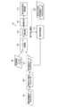
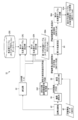
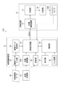
- FIG. 1 is a block diagram showing a system configuration of a printing system including a color conversion table creating apparatus according to an embodiment of the present invention.
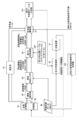
- FIG. 2 is a block diagram showing an overall outline of a printing system to which the color conversion table creating apparatus according to the first embodiment is applied.
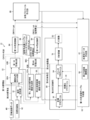
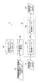
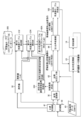
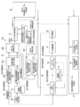
- FIG. 3 is a block diagram showing a first main configuration of the printing system.
- FIG. 4 is a block diagram showing a modification of the first main configuration.
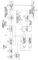
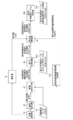
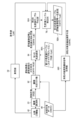
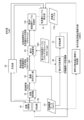
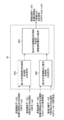
- FIG. 5 is a block diagram showing a second main configuration.
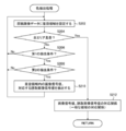
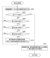
- FIG. 6 is a flowchart showing a processing procedure according to the second main configuration.
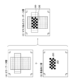
- FIG. 7 is a block diagram illustrating a specific example of image alignment processing in the image association unit.
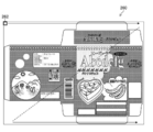
- FIG. 8A shows an example of document image data.
- FIG. 8A shows an example of document image data.
- FIG. 8B is a diagram illustrating an example of the target printed matter.
- FIG. 9 is a block diagram of a configuration for performing image association processing including preprocessing.
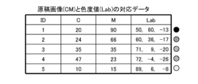
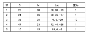
- FIG. 10 is a chart showing an example of correspondence data between document image signals and chromaticity values.
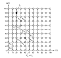
- FIG. 11 is an explanatory diagram showing lattice points in the color space of the document image data corresponding to the input side of the color conversion table.
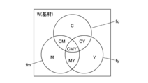
- FIG. 12 is an explanatory diagram of a chromaticity value calculation method using the Neugebauer model.
- FIG. 13 is a principal block diagram relating to the second color conversion unit.
- FIG. 14 is a chart showing an example of correspondence data of a document image signal, a target chromaticity value, a printing chromaticity value, and a differential chromaticity value.
- FIG. 10 is a chart showing an example of correspondence data between document image signals and chromaticity values.
- FIG. 11 is an explanatory diagram showing lattice points in the color space of the document
- FIG. 15 is a conceptual diagram when a color correction table is used.
- FIG. 16 is a diagram showing an example of a graphical user interface when selecting a colorimetric position in a configuration in which a spectrocolorimeter is used together.
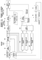
- FIG. 17 is a block diagram showing a configuration according to a first example of the colorimetric value utilization method.
- FIG. 18 is a block diagram showing a configuration in which a function for replacing chromaticity values with colorimetric values is added to the second main configuration shown in FIG.
- FIG. 19 is a block diagram showing a configuration example provided with means for selecting and correcting a scanner profile based on a colorimetric value in the first main configuration.
- FIG. 16 is a diagram showing an example of a graphical user interface when selecting a colorimetric position in a configuration in which a spectrocolorimeter is used together.
- FIG. 17 is a block diagram showing a configuration according to a first example of the colorimetric value utilization method.
- FIG. 20 is a block diagram showing a configuration example provided with means for selecting and correcting a scanner profile based on a colorimetric value in the second main configuration.
- FIG. 21 is a block diagram showing a modified example of the configuration shown in FIG.
- FIG. 22 is a block diagram showing a modified example of the configuration shown in FIG.
- FIG. 23 is a flowchart showing an example of a color extraction method.
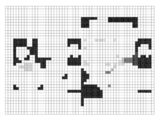
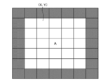
- FIG. 24 is a conceptual diagram illustrating an example of processing for setting a region of interest in document image data.
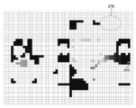
- FIG. 25 is a diagram illustrating an example of read image data obtained from the image reading unit.
- FIG. 26 is a diagram showing an example of a region extracted from the document image data shown in FIG. 24 as satisfying the first extraction condition.
- FIG. 21 is a block diagram showing a modified example of the configuration shown in FIG.
- FIG. 22 is a block diagram showing a modified example of the configuration shown in FIG.
- FIG. 23 is a flowchart showing an example of a color extraction
- FIG. 27 is a diagram showing an example of a region extracted from the read image data shown in FIG. 25 as satisfying the second extraction condition.
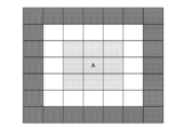
- FIG. 28 is an explanatory diagram used for explaining a region around the region of interest.
- FIG. 29 is a plan view of the entire scan surface used for explaining a low-reliability region in the scanner used in the image reading unit.
- FIG. 30 is a chart in which an example of “weight” indicating the importance of color is added to the correspondence data shown in FIG.
- FIG. 31 is a chart in which an example of “weight” indicating the importance of color is added to the correspondence data shown in FIG.
- FIG. 32 is an explanatory diagram used to explain how to obtain the center of gravity of the white region.
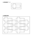
- FIG. 33 is a schematic diagram showing an example of document image data for package printing.
- FIG. 33 is a schematic diagram showing an example of document image data for package printing.
- FIG. 34 is a flowchart of color extraction processing in which the presence or absence of surface processing is added to the color extraction conditions.
- FIG. 35 is a block diagram showing a system configuration of a printing system according to another embodiment of the present invention.
- FIG. 36 is a block diagram showing a second main configuration in the printing system of FIG.
- FIG. 37 is a block diagram showing a configuration example of the color conversion data creation unit shown in FIG.
- FIG. 38 is a block diagram showing a system configuration of a printing system according to another embodiment of the present invention.
- FIG. 1 is a block diagram showing the overall configuration of a printing system including a color conversion table creation device according to an embodiment of the present invention.
- the printing system 10 includes an image editing device 12, a print control device 14, and a printing unit 16.
- the image editing device 12 serves as a color conversion table creation device according to the embodiment, and performs a color conversion table creation process necessary for color reproduction by the printing unit 16.
- the image editing device 12 is a device that performs image processing such as color conversion processing, image data processing, or editing using a color conversion table.
- the print image data created by the image editing device 12 is sent to the print control device 14.
- the print control device 14 controls the printing operation by the printing unit 16 based on the print image data created by the image editing device 12.
- the print control device 14 may include a halftone processing unit that converts continuous tone image data into binary or multilevel halftone image data.
- the image editing device 12 and the print control device 14 are illustrated as separate configurations, but a configuration in which the functions of the print control device 14 are installed in the image editing device 12 is also possible. For example, a configuration in which one computer functions as the image editing device 12 and the print control device 14 is possible.
- the printing unit 16 is an image forming unit that performs printing in accordance with the control of the print control device 14.
- the printing method in the printing unit 16 and the type of color material to be used are not particularly limited.
- various printers such as an inkjet printing apparatus, an electrophotographic printer, a laser printer, an offset printing apparatus, or a flexographic printing apparatus can be adopted.
- printer is understood to be synonymous with terms such as a printing device, a printing device, an image recording device, an image forming device, or an image output device.
- a printing device a printing device, an image recording device, an image forming device, or an image output device.
- the color material, ink, toner, or the like can be used according to the type of the printing unit 16.
- a plateless digital printing apparatus is assumed, and a configuration in which the printing control device 14 and the printing unit 16 are combined is described as the printing device 18.
- a mode in which the printing control device 14 and the printing unit 16 are integrally combined to form the printing device 18 is also possible.
- the printing control device 14 and the printing unit 16 are configured as separate devices, and wired or wireless.
- a mode in which signals are exchanged by communication connection is also possible.
- the system configuration includes a plate making apparatus such as a plate recorder that creates a printing plate from image data in addition to the printing control apparatus 14.
- a configuration in which the plate making device, the print control device 14, and the printing unit 16 are combined corresponds to the printing device 18. Illustration of the plate making apparatus is omitted.
- the printing system 10 of the present embodiment uses an inkjet printing apparatus capable of forming a color image using four colors of ink of cyan, magenta, yellow, and black as an example of the printing apparatus 18.
- cyan, magenta, yellow, and black colors may be expressed using C, M, Y, and K.
- cyan, magenta, yellow, and black may be collectively referred to as CMYK.
- ink colors and their combinations are not limited to this example.
- a mode in which light color ink such as light cyan or light magenta is added, and a mode in which special color ink such as orange or green is used are also possible.
- light cyan may be expressed using LC, light magenta using LM, and orange using O.
- the image editing apparatus 12 includes an image data input unit 20, an image data storage unit 22, an image processing unit 24, and a control unit 26.
- the image editing device 12 includes an image reading unit 30, a colorimeter, a display unit 34, and an input device 36.
- the image editing device 12 can be realized by a combination of computer hardware and software.
- the image editing device 12 can be realized as a function of the RIP device.
- RIP is an abbreviation for Raster Image Processor.
- software terms can be treated as synonymous with program terms.
- the image data input unit 20 is a data acquisition unit for taking in the original image data 40.
- the image data input unit 20 can be configured by a data input terminal that takes in the document image data 40 from an external or other signal processing unit in the apparatus.
- a wired or wireless communication interface unit may be employed, a media interface unit for reading and writing an external storage medium such as a memory card may be employed, or an appropriate one of these modes may be employed. It may be a combination.
- External storage media such as memory cards include what are called removable disks.
- the target printed material 42 is a color sample printed material of the target color to be reproduced, and is given as an actual color sample.
- the document image data 40 is digital image data representing the image content to be printed.
- the document image data 40 is image data indicating the pattern of the document image of the target printed matter 42.
- the printer or printing apparatus that outputs the target printed matter 42 as an image, the printing conditions, and the like may be unknown. Any printer can be used as the output means for the target printed matter 42.
- the document image data 40 and the target printed material 42 are provided from the requester of printing.
- the document image data 40 may be entire image data indicating the entire image content on the printing surface of the target printed matter 42, data of image components as a part of an image recorded on the printing surface, or document components. It may be the data.
- the data format of the document image data 40 is not particularly limited.
- 8-bit image data expressing each color of CMYK with 256 gradations is used as the document image data 40.
- the original image data 40 is not limited to the CMYK signal, and may be in the form of an RGB signal, or a combination of a CMYK signal and a special color signal. It may be a format. Also, the number of gradations of the signal or the number of bits of the signal is not limited to this example.
- the CMYK signal is a color image signal expressed using cyan, magenta, yellow, and blue colors.
- the RGB signal is a color image signal expressed using red, green, and blue colors.
- the image data storage unit 22 is means for storing document image data 40 acquired via the image data input unit 20. Document image data 40 captured from the image data input unit 20 is stored in the image data storage unit 22.
- the image reading unit 30 reads a printed matter such as the target printed matter 42 or the printed matter 50 printed by the printing apparatus 18, converts the optical image into electronic image data, and creates read image data as a color image representing the read image.
- a color image scanner capable of outputting the read image as RGB image data can be used for the image reading unit 30.
- the read image data is shown in FIG.
- a scanner capable of acquiring read image data represented by image signals of RGB color components is used.
- a read image acquired from the image reading unit 30 may be referred to as a scan image.
- a camera can be used instead of the scanner.
- the image reading unit 30 functions as a means for acquiring read image data of the target printed matter 42. Further, the image reading unit 30 functions as a unit that reads the printed matter 50 printed by the printing device 18 and acquires the read image data of the printed matter 50. The read image data acquired via the image reading unit 30 is sent to the image processing unit 24.
- the image processing unit 24 creates a color conversion table based on the read image data acquired from the image reading unit 30 and the document image data 40.
- the image processing unit 24 has a function of performing color conversion processing using the color conversion table on the document image data 40 and generating image data to be transferred to the printing apparatus 18.
- the image processing unit 24 has a function of performing processing such as resolution conversion and gradation conversion on the document image data 40 and the read image data as necessary. Details of processing contents in the image processing unit 24 will be described later.
- the printing system 10 shown in the present embodiment may include a colorimeter in order to increase the accuracy of color information of the read image by the image reading unit 30.
- the color measuring device corresponds to a color measuring unit.
- a spectrocolorimeter is used as the colorimeter. The spectrocolorimeter measures the reflectance of the visible light wavelength region at a predetermined wavelength increment, calculates the XYZ value using the XYZ color matching function representing the human visual spectral sensitivity, and obtains the colorimetric value To do.
- a spectrocolorimeter used as a colorimeter measures, for example, a reflectance of a wavelength region of 380 nm or more and 730 nm or less, which is a wavelength region of visible light, with a wavelength increment of 10 nm, and a colorimetric value Get.
- the wavelength step size is sometimes called a wavelength step.
- the XYZ values obtained from the colorimeter can be converted into color coordinate values in a device-independent color space such as the L * a * b * color system by a known conversion formula.
- the L * a * b * color system is used as the color system of the device-independent color space representing the target value of the color.
- the color system is not limited to this. Absent.
- an XYZ color system using a stimulus value Y including brightness or brightness, a stimulus value X of color, and a stimulus value Z of color, brightness Y, chromaticity coordinates x, and chromaticity defined by the International Commission on Illumination In addition to the Yxy color system using the coordinate y, the L * u * v * color system, the HSV color system using the hue H, the saturation S, and the lightness V, the hue H, the saturation S, and the luminance L HLS color system using, it is possible to use the luminance Y, chrominance C b, and a YC b C r color system with a color difference C r.
- the color system may be described as a color coordinate system.
- the hue may be expressed by using the initial letter H of hue in English.
- Saturation may be expressed using the initial letter S of saturation in English.
- the lightness may be expressed using the initial letter V of value in English or the initial letter B of brightness.
- Luminance may be expressed using the initial letter L in English.
- the color space of the L * a * b * color system is denoted as the Lab color space
- the chromaticity value represented by the coordinate value of the Lab color space is denoted as the Lab value.
- image data in which the image signal value of each pixel is described by a Lab value may be referred to as a Lab image.
- a color value represented by the color system coordinates of a device-independent color space that is a device-independent color space, such as the Lab color space, is expressed as a chromaticity value.
- Image processing unit 24 creates the color conversion table by taking into consideration the information of the colorimetric values acquired from the colorimeter in addition to the read image data obtained from the image reading unit 30. Can do.
- the control unit 26 controls the operation of each unit of the image editing device 12.
- the display unit 34 and the input device 36 function as a user interface.
- the input device 36 can employ various means such as a keyboard, a mouse, a touch panel, or a trackball, and may be an appropriate combination thereof.
- positioned the touch panel on the screen of the display part 34 is also possible.
- the operator uses the input device 36 while viewing the contents displayed on the screen of the display unit 34 to input printing conditions, select an image quality mode, specify a colorimetric position, input auxiliary information, edit auxiliary information, or Various information such as information retrieval can be input. Further, the input content and other various information can be confirmed through the display on the display unit 34.
- FIG. 2 is a block diagram showing an overall outline of the printing system 10 to which the color conversion table creating apparatus according to the first embodiment is applied.
- FIG. 2 the same elements as those described in FIG. In the present embodiment, a configuration in which the colorimeter shown in FIG. 1 is omitted will be described.
- the printing system 10 is based on a given target print 42 and original image data 40, and a print 50 that reproduces a color equivalent to the target print 42 by the printing device 18 or is equivalent to the target print 42.
- a function of performing color matching is provided so that a printed material 50 aiming at color reproduction can be obtained.
- the equivalent color includes a range of color differences that can be permitted by the client and includes a range that can be satisfied as being substantially equivalent.
- the printing system 10 includes an image reading unit 30. Further, as shown in FIG. 2, read image data obtained from the image reading unit 30, original image data 40, and the like.
- the image correlation part 62 which performs the correlation of is provided.
- the read image data includes read image data of the target print product 42 and read image data of the print product 50.
- the term read image data is used when it is not necessary to distinguish between the two.
- the read image data of the target printed matter 42 uses the term of the target printed matter read image data
- the read image data of the printed matter 50 uses the term of the printed matter read image data
- the image association unit 62 includes an image alignment unit 62A that performs alignment processing between the target printed material read image data and the document image data 40 or alignment processing between the printed material read image data and the document image data 40.
- the original image data 40 here corresponds to original image data before the resolution reduction processing.
- the image associating unit 62 includes a first color extracting unit 62B that extracts color information from image areas at corresponding positions of both image data subjected to the alignment processing by the image aligning unit 62A.
- the color extraction process is a process for acquiring color information for each unit area.
- color information may be extracted in units of pixels at corresponding positions, or color information may be acquired from a unit area having an area larger than the area of one pixel.
- a square region having a side of 1 millimeter can be given.
- the number of pixels constituting the unit area for color extraction can be set to an arbitrary number of two or more.
- a color extraction condition for example, when two condition elements are satisfied, that is, the target region that is the unit region of interest does not include an edge and the color difference within the target region is equal to or less than a threshold value
- the color of the region of interest can be extracted.
- Edge is a portion where the shading or brightness or color in the image is changing abruptly.
- the color extraction condition described above is a condition for extracting a uniform region in which a color error or variation is allowed in a range where the color difference is equal to or less than a threshold value.
- the color extraction conditions are not limited to this example, and other extraction conditions can be defined.
- the resolution of the read image data is the first resolution.
- the first resolution is 600 dots per inch. Note that any resolution can be applied to the resolution of the target print 42 and the print 50 to be read.
- the resolution of the target print product 42 to be read and the print product 50 is set to a resolution exceeding 600 dots per inch.
- the resolution of the document image data is the second resolution.
- the second resolution depends on the given document image data 40, and various values are assumed.
- the second resolution can be matched to the first resolution.
- the second resolution is 600 dots per inch.
- the first low-resolution image creation unit 63A creates low-resolution image data having a third resolution that is lower than the first resolution, based on the read image data after the alignment processing by the image alignment unit 62A. Process. In other words, the first low-resolution image creating unit 63A obtains a resolution lower than the first resolution from the image data of the first resolution related to the read image that has undergone the alignment process and has been aligned by the image alignment unit 62A. The image data having the third resolution is created.
- the term “low resolution read image data” is used for the read image data that has undergone the low resolution processing.
- the low-resolution read image data includes low-resolution target print-read image data obtained by reducing the target print-read image data and low-resolution print read-image data obtained by reducing the print read-image data.
- the second low-resolution image creation unit 61 performs a resolution reduction process for creating low-resolution document image data having a fourth resolution that is a resolution lower than the second resolution, based on the document image data 40.
- the second low-resolution image creation unit 61 uses the second resolution image data related to the document image that has been aligned by the image alignment unit 62A, so that the fourth resolution is less than the second resolution. Image data having resolution is created.
- the third resolution is preferably a resolution that approximates the frequency characteristics of human vision. According to paragraph 0069 of Japanese Patent Laid-Open No. 2006-197457, it is described that the output resolution approximating the frequency characteristics of human vision may be about 25 dots per inch or more and 120 dots per inch or less.
- the third resolution in this embodiment is preferably about 25 dots per inch or more and 120 dots per inch or less, and more preferably 50 dots per inch or more and 100 dots per inch or less. In this embodiment, an example in which 50 dots per inch is adopted as a specific value of the third resolution will be described.
- the fourth resolution is preferably a value close to the third resolution, and in particular, the fourth resolution is more preferably the same resolution as the third resolution.
- the fourth resolution is more preferably the same resolution as the third resolution.
- an example will be described in which 50 dots per inch equivalent to the third resolution is adopted as a specific value of the fourth resolution.
- Each of the first low-resolution image creation unit 63A and the second low-resolution image creation unit 61 uses a thinning process or a pixel interpolation method to thin out pixels at a certain ratio with respect to input image data. By performing pixel interpolation processing for obtaining values, resolution reduction processing for creating image data of 50 dots per inch is performed. Note that the first low-resolution image creation unit 63A and the second low-resolution image creation unit 61 can have the same processing content, and the first low-resolution image creation unit 63A and the second low-resolution image creation unit 63A It can be configured by a common resolution reduction processing unit in which the processing functions of the resolution image creation unit 61 are integrated.
- an image averaged by applying a blur filter such as a Gaussian filter may be regarded as a low-resolution image.
- a blur filter such as a Gaussian filter
- an effect equivalent to the resolution conversion by the thinning process or the pixel interpolation process described above can be obtained in that an average color can be extracted from an image area having a dull edge and a somewhat structured structure.
- the low-resolution read image data creation process by the first low-resolution image creation unit 63A and the low-resolution document image data creation process by the second low-resolution image creation unit 61 are respectively image positions by the image registration unit 62A. It is performed after the process of combining. If the image alignment process is performed after the low resolution read image data and the low resolution original image data are created, the image alignment process is performed based on the extremely low resolution image data. This is because the accuracy of alignment deteriorates.
- the second color extraction unit 62C includes the low-resolution read image data created by the first low-resolution image creation unit 63A and the original document image after the resolution reduction processing created by the second low-resolution image creation unit 61. A process for extracting color information at a corresponding position from low-resolution original image data that is data is performed.
- the number of colors extracted by the second color extraction unit 62C is smaller than the number of colors extracted by the first color extraction unit 62B, but a more average color is extracted. become.
- the low resolution read image data is created from the read image data of the target print product 42 or the read image data of the print product 50.
- the low resolution original image data is created from the original image data 40.
- the second color extraction unit 62C obtains data in which the correspondence between the CMYK values extracted from the low-resolution document image data and the RGB values extracted from the third-resolution image data is specified.
- the image associating unit 62 obtains data indicating the correspondence between the CMYK values of the document image data 40 and the RGB values of the read image data.
- the correspondence can be converted into data in the form of a lookup table.
- the first color conversion unit 64 converts the color information represented by the signal value of the color component of the device dependent color space obtained from the image reading unit 30 into the signal value of the color component of the device independent color space (Lab in this example). ) Is converted into color information represented by In the present embodiment, RGB signal values are applied as signal values of color components in the device-dependent color space. The Lab value is applied as the signal value of the color component in the device-independent color space.
- a known image alignment method can be used for the alignment process, which is the process of associating the image positions of the two image data to be compared.
- the technique described in paragraphs ⁇ 0064>- ⁇ 0068> of Patent Document 2 can be used as an image alignment method. Details of the image alignment processing will be described later.
- the first color conversion unit 64 uses the read color conversion table 68 to perform color conversion processing for converting color information in the RGB color space into color information in the Lab color space.
- the read color conversion table 68 is a color conversion table corresponding to the scanner profile.
- the read color conversion table 68 is a color conversion table that represents a correspondence relationship between RGB values, which are read image signal values in the device-dependent color space obtained from the image reading unit 30, and device-independent Lab values.
- the Lab color space is used as the device-independent color space, but other device-independent color spaces can also be used.
- the color space of the read image signal representing the read image data obtained from the image reading unit 30 corresponds to the first color space
- the device-independent color space exemplified by the Lab color space corresponds to the second color space.
- the color conversion processing function by the first color conversion unit 64 corresponds to the first color conversion function.
- the RGB value in the color information indicating the correspondence obtained by the second color extraction unit 62C is converted into the Lab value by the first color conversion unit 64.
- the read image is a concept including the image on the target printed matter 42 and the image on the printed matter 50 shown in FIG.
- the target profile creation unit 66 shown in FIG. 2 has a correspondence relationship between the first color information created through the processing of the image alignment unit 62A, the first color extraction unit 62B, and the first color conversion unit 64. And a target profile based on the correspondence relationship between the second color information created through the processing of the first low-resolution image creation unit 63A, the second color extraction unit 62C, and the first color conversion unit 64. 92 color conversion tables are created.
- This color conversion table is a table that prescribes a four-dimensional to three-dimensional conversion relationship between CMYK and Lab.
- the correspondence relationship between the first color information is a correspondence relationship between the original image represented by the CMYK value which is the signal value of the third color space, the chromaticity value of the target printed matter 42, and the chromaticity value of the printed matter 50. is there.
- the correspondence relationship between the first color information corresponds to the color information of the first resolution.
- the correspondence relationship between the second color information is represented by CMYK values that are signal values of the third color space, and the original image obtained by reducing the original image to the fourth resolution and the lower resolution to the third resolution.
- CMYK values that are signal values of the third color space
- This is a correspondence relationship between the chromaticity value of the target printed matter 42 and the chromaticity value of the printed matter whose resolution has been reduced to the third resolution.
- the correspondence relationship between the second color information corresponds to the color information of the third resolution.
- the target profile 92 is also called a target profile or an input profile.
- the color conversion table of the target profile 92 is a color conversion table that describes the conversion relationship from CMYK to Lab in which the target color of the CMYK signal of the document image data 40 is defined in the Lab space that is a device-independent color space.
- the target profile 92 corresponds to the input color conversion table.
- the target profile creation unit 66 shown in FIG. 2 first creates a color conversion table based on the correspondence relationship between the second color information, and then further adds a color conversion table to the color conversion table.
- the final color conversion table is created by correcting the table by adding the correspondence relationship between the color information of 1.
- the first color information correspondence data is added to the once created color conversion table to create a color conversion table.
- a colorimetric position associating unit that performs a process of associating the colorimetric position from which the colorimetric value is obtained by the colorimeter with the position in the document image data 40
- a first profile correction unit that corrects the read color conversion table 68 shown in FIG. 2 using colorimetric values obtained from the device.
- a configuration including a chromaticity value replacement unit that directly corrects the chromaticity value of the Lab image after color conversion by the first color conversion unit 64 is also possible.
- the first profile correction unit that is not performed and the chromaticity value replacement unit that is not illustrated are included in the image processing unit 24 of the image editing apparatus 12 described with reference to FIG.
- the image processing unit 24 includes a second color conversion unit 80 that performs color conversion of the document image data 40, a first color conversion table creation unit 82, and a color conversion data creation unit. 85.
- the second color conversion unit 80 performs conversion processing of the document image data 40 using the target profile 92 conforming to the ICC profile format and the printer profile 94, and an image signal in a data format suitable for the printing apparatus 18. Create The color conversion function of the second color conversion unit 80 corresponds to the second color conversion function.
- the second color conversion unit 80 may convert the document image data 40 into print data having the same resolution as that of the document image data 40, or the document image data 40 has the document image data 40. It may be converted into print data having a resolution different from the resolution.
- ICC is an abbreviation for International Color Consortium.
- An ICC profile is a series of data that characterizes color input / output devices and color spaces in accordance with standards published by the International Color Consortium in color management.
- the printer profile 94 is also called an output profile.
- the color conversion table of the printer profile 94 is a color conversion table that defines the correspondence between the CMYK signal output to the printing device 18 and the Lab value of the output color from the printing device 18.
- the color conversion table of the printer profile 94 corresponds to the output color conversion table.
- the color conversion table of the printer profile 94 defines a conversion relationship to output CMYK values corresponding to Lab values to be reproduced, that is, a conversion relationship from chromaticity values in the Lab color space to signal values in the CMYK color space. It has become.
- the first color conversion table creation unit 82 includes a differential chromaticity value calculation unit 84.
- the difference chromaticity value calculation unit 84 performs Lab conversion of the target printed matter 42, which is a target chromaticity value created by color conversion from the read image data of the target printed matter 42 by the first color converting unit 64, and the read image of the printed matter 50.
- a Lab difference that is a difference chromaticity value that represents a difference in Lab values of the printed matter 50 that is a print chromaticity value created from the data is calculated.
- the first color conversion table creation unit 82 performs a process of correcting the target profile 92 based on the difference information.
- the first color conversion table creating unit 82 is not limited to the configuration for correcting the target profile 92, but may be configured to correct the printer profile 94.
- the first color conversion table creation unit 82 creates a color correction profile 96 based on the difference information, and combines the target profile 92, the color correction profile 96, and the printer profile 94, thereby combining the second color conversion unit 80.
- the color conversion table can be modified.
- the color conversion data creation unit 85 creates a third color information correspondence based on the first color information correspondence and the second color information correspondence.
- FIG. 37 is a block diagram showing the configuration of the color conversion data creation unit 85.
- the color conversion data creation unit 85 includes a first color information correspondence creation unit 85A that creates a first color information correspondence, and a second color information correspondence that creates a second color information correspondence. It includes a creating unit 85B and a third color information correspondence creating unit 85C that creates a third color information correspondence.
- the first color information correspondence creation unit 85A creates a first data set.
- the first data set defines the conversion relationship of CMYK-Lab H1 -Lab H2 .
- CMYK in the first data set is a CMYK value of document image data having the second resolution.
- Lab H1 is a chromaticity value of the target printed matter 42 corresponding to the target printed matter read image data having the first resolution.
- Lab H2 is a chromaticity value of the printed matter 50 corresponding to the printed matter read image data having the first resolution.
- the first data set is created by applying a logical product condition to CMYK-Lab H1 and CMYK-Lab H2 , and extracting Lab H1 and Lab H2 in which the CMYK values of both coincide.
- An embodiment in which Lab H1 and Lab H2 in which both CMYK values match is preferable, but an error that does not affect the color difference between the two (for example, in the CMYK value represented by an 8-bit digital value, two digital values ( CMYK values including an error of plus or minus 1 digital value) are included in the matching CMYK values.
- the second color information correspondence creation unit 85B creates a second data set.
- the second data set defines the conversion relationship of CMYK-Lab L1 -Lab L2 .
- CMYK in the second data set is a CMYK value of low-resolution document image data having the fourth resolution.
- Lab L1 is the chromaticity value of the target printed matter 42 corresponding to the low resolution target printed matter read image data having the third resolution, and corresponds to the low resolution target chromaticity value.
- Lab L2 is the chromaticity value of the printed matter 50 corresponding to the low resolution printed matter read image data having the third resolution or the low resolution printed matter read chromaticity value image data, and corresponds to the low resolution printed chromaticity value.
- the second data set is created by applying a logical product condition to CMYK-Lab L1 and CMYK-Lab L2 , and extracting Lab L1 and Lab L2 having the same CMYK value. It is preferable to extract Lab L1 and Lab L2 in which both CMYK values match. However, CMYK values including errors that do not affect the color difference between the two (for example, CMYK values represented by 8-bit digital values, errors of two digital values (plus or minus one digital value)) match CMYK values. It can be included in the value.
- the third color information correspondence creation unit 85C applies a logical sum condition that gives priority to the first data set to the first data set and the second data set, and performs color matching between the original image and the target printed matter. Create correspondence with printed materials.
- the OR condition giving priority to the first data set is a condition that adopts the Lab value of the first data set when there is a common CMYK value between the first data set and the second data set. is there.
- a mode in which CMYK values are common between the first data set and the second data set is preferable.
- the present invention is not limited to this.
- a CMYK value represented by an 8-bit digital value a CMYK value including an error of two digital values (plus or minus one digital value) is included in a common CMYK value. Can do.
- the operation of performing color matching between the target printed material 42 and the printed material 50 using the image reading unit 30 can be broadly divided into the following two stages.
- the first step is to estimate the target profile by reading the target print 42 with the image reading unit 30, that is, to create the target profile.
- each of the target printed matter 42 and the printed matter 50 printed by the printing apparatus 18 is read by the image reading unit 30 and applied to the second color converting unit 80 based on these reading results. Is to improve the color matching accuracy.
- first main configuration The configuration corresponding to the first stage is referred to as “first main configuration”, and the configuration corresponding to the second stage is referred to as “second main configuration”.
- first main configuration the configuration corresponding to the first stage
- second main configuration the configuration corresponding to the second stage
- FIG. 3 is a block diagram showing the flow of processing in the first main configuration.
- the document image data 40 is described as CMYK, the read image data as RGB, and the chromaticity value as Lab.
- the color space to be applied in implementing the present invention is not limited to this example.
- the document image data 40 may be RGB image data, CMY image data, or image data in which a CMYK signal and a special color signal are combined.
- the chromaticity values represented by the device-independent color space may also be values of the XYZ color system, the Luv color system, and other color systems. The same applies to the arbitrary color space.
- the target profile creation process according to the first main configuration is performed according to the following procedure.
- the target printed matter 42 is read by the image reading unit 30.
- read image data acquisition step of the target printed matter read image data is acquired.
- an RGB image is obtained as read image data.
- the acquired read image data is sent to the image association unit 62.
- the image alignment unit 62A performs a process of associating the positional relationship between the read image data and the document image data 40.
- the document image data acquisition process which is a process for taking in the document image data 40, may be performed before the read image data acquisition process of the target print product or after the read image data acquisition process of the target print product.
- the correspondence between the pixel positions of the original image data 40 and the read image data of the target printed matter 42 is specified, and the signal value of the original image data represented by the CMYK values and the target printed matter represented by the RGB values.
- the original image data and the read image data of the target print are associated with the positional relationship with the signal value of the read image data.
- the second low-resolution image creation unit 61 performs a resolution reduction process on the document image data 40 associated with the positional relationship with the target printed matter read image data. And low resolution original image data having the fourth resolution is created.
- the first low-resolution image creation unit 63A performs a resolution reduction process on the target printed material read image data associated with the positional relationship with the document image data.
- the low resolution target printed matter read image data having the third resolution is generated.
- the function of the first low-resolution image creation unit 63A corresponds to the first low-resolution image creation function.
- the first color extraction unit 62B performs color extraction processing for extracting color information from the original image data 40 and the read data of the target printed matter 42. Further, the second color extraction unit 62C performs color extraction processing for extracting color information from the low-resolution original image data and the low-resolution target printed material read image data. Details of the color information extraction process will be described later.
- the first color conversion unit 64 uses the color conversion table of the read color conversion table 68, which is the first color conversion table 68A, and has performed color extraction processing. For the printed material read image data and the low resolution target printed material read image data subjected to the color extraction process, a process of converting RGB values into Lab values is performed.
- the first color converting step represents a step of performing processing for converting RGB values representing target printed matter read image data having the first resolution into Lab values, and low resolution target printed matter read image data having the third resolution.
- a process of converting RGB values into Lab values is included.
- the first color conversion table 68A is a color conversion table of the read color conversion table 68 shown in FIG. 2, and includes a signal value of read image data represented by RGB values and a chromaticity value represented by Lab values. Correspondence is defined. That is, the first color conversion table 68A shown in FIG. 3 is a table that defines the conversion relationship from RGB signal values to Lab values for converting input RGB signal values into output Lab values.
- the first color converter 64 converts the signal value of the read image data into a chromaticity value in a device-independent color space.
- the second color conversion table creation unit 66A corresponds to the target profile creation unit 66 shown in FIG.
- the second color conversion table 92A created by the second color conversion table creation unit 66A shown in FIG. 3 is a color conversion table that defines the conversion relationship from signal values of document image data to chromaticity values. , A color conversion table that defines the conversion relationship from CMYK values to Lab values.
- the second color conversion table 92A shown in FIG. 3 corresponds to the color conversion table of the target profile 92 representing the target color shown in FIG. 2, and the second color conversion table 92A of the target profile 92 applied to the second color conversion unit 80. It can be used as a color conversion table.
- FIG. 4 shows a modification of the configuration shown in FIG. 4, elements that are the same as or similar to those described in FIG. 3 are given the same reference numerals, and descriptions thereof are omitted.
- the configuration shown in FIG. 4 is a configuration in which the processing order of the image association unit 62 and the first color conversion unit 64 is changed compared to the configuration shown in FIG.
- the RGB read image data acquired from the image reading unit 30 is converted into the Lab value from the RGB value by the first color conversion unit 64, and is expressed by the Lab value. Read chromaticity value image data is created.
- the read chromaticity value image data includes the target printed matter read chromaticity value image data based on the read image data of the target printed matter 42 and the printed matter read chromaticity value image data based on the read image data of the printed matter 50 shown in FIG. It is.
- the first low-resolution image creation unit 63A performs a resolution reduction process on the target printed matter read chromaticity value image data to create low-resolution target printed matter read chromaticity value image data having a third resolution.
- the second low-resolution image creation unit 61 performs a resolution reduction process on the document image data 40 to create low-resolution document image data having a fourth resolution.
- the function of the second low-resolution image creation unit 61 corresponds to the second low-resolution image creation function.
- the first color extraction unit 62B performs color extraction processing for extracting color information from the document image data and the target printed matter read chromaticity value image data.
- the second color extraction unit 62C performs color extraction processing for extracting color information from the low-resolution original image data and the low-resolution target printed material read chromaticity value image data. Using the data indicating the correspondence between the signal value and the chromaticity value of the original image data created in this way, and the data indicating the correspondence between the signal value and the chromaticity value of the original image data having a reduced resolution.
- a second color conversion table 92A is created.
- FIG. 5 is a block diagram showing a second main configuration.
- the third color conversion table creation unit 102 in FIG. 5 is a processing unit corresponding to the first color conversion table creation unit 82, the difference chromaticity value calculation unit 84, and the color conversion data creation unit 85 shown in FIG. is there.
- the second main configuration is similar to the first main configuration described in FIGS. 3 and 4, and the image association unit 62 and the first color of the configuration shown in FIG. A configuration in which the processing order of the conversion unit 64 is changed can be employed, and even when such a configuration is employed, the same effect as in FIG. 5 can be obtained.
- step S ⁇ b> 110 of FIG. 6 the input color conversion table and the output color conversion table are set in the second color conversion unit 80.
- the input color conversion table is the color conversion table of the target profile 92 described in FIG. 2, and the output color conversion table is the color conversion table of the printer profile 94.
- the input color conversion table and the output color conversion table set in step S110 of FIG. 6 are color conversion tables given as initial settings in the second color conversion unit 80.
- an input color conversion table of a standard profile such as Japan Color
- a color conversion table created in the past in the printing system 10 can be applied.
- the output color conversion table a table defined for each printing device 18 according to the type of printing paper to be used can be used. Japan Color is a registered trademark. Japan Color is sometimes referred to as Japan Color.
- step S112 in FIG. 6 the second color is converted using the set input color conversion table and output color conversion table.
- the conversion unit 80 performs color conversion on the document image data 40 to create print image data suitable for input to the printing apparatus 18. This process corresponds to step S112 in FIG. 6, the second color conversion process, and the document image color conversion process.
- the CMYK document image data 40 is converted into CMYK print image data using the input color conversion table and the output color conversion table of the second color conversion unit 80.
- the print image data created by the second color conversion unit 80 is sent to the printing device 18, and printing is performed by the printing device 18. That is, the printed matter 50 is obtained by the printing step S114 of FIG.
- step S118 of FIG. 6 the printed matter 50 obtained in the printing step S114 is compared with the target printed matter 42, and it is determined whether or not the printed matter 50 achieving the target color reproduction is obtained.
- Examples of the determination method in step S118 include the following two methods. That is, the first example of the determination method is a method of determining by visual comparison between the printed material 50 and the target printed material 42.
- a second example of the determination method is a method of quantitatively determining based on a difference between chromaticity values acquired by reading the printed material 50 and the target printed material 42 by the image reading unit 30.
- the average color difference or the maximum color difference is calculated, and if the average color difference or the maximum color difference is below a certain threshold value, it is determined that the target color reproduction has been achieved.
- both the average color difference and the maximum color difference may be calculated, and the average color difference and the maximum color difference may be combined for determination. In this case, for example, when the average color difference is equal to or smaller than the first threshold value and the maximum color difference is equal to or smaller than the second threshold value, it can be determined that the target color reproduction is achieved.
- an evaluation function for obtaining another evaluation value (index value) by combining the average color difference and the maximum color difference is defined, and the evaluation value obtained from the evaluation function is compared with a threshold value defined as a criterion. Thus, it may be determined whether or not the target color reproduction has been achieved.
- the determination is made based on the difference between the chromaticity values obtained in step S124 and step S134 described later.
- the quantitative determination method based on the difference in chromaticity values shown as the second example can be adopted instead of or in combination with the determination method by visual comparison shown as the first example.
- step S118 If it is determined in step S118 that a printed material 50 having achieved color reproduction equivalent to the target printed material 42 is obtained, the determination in step S118 is Yes, and the color matching process can be terminated.
- step S118 determines whether the target color print 50 is obtained in the determination in step S118. If the target color print 50 is not obtained in the determination in step S118, the determination in step S118 is No and the process proceeds to step S120.
- step S120 the printed material 50 is read by the image reading unit 30, and the read image data of the printed material 50 is acquired.
- an RGB image is obtained as printed material read image data that is read image data of the printed material 50, and the acquired printed material read image data is sent to the image alignment unit 62A.
- the image alignment unit 62A associates the positional relationship between the printed material read image data and the document image data 40.
- This process corresponds to step S122 in FIG.
- the document image data acquisition process which is a process for capturing the document image data 40, may be performed before or after the printed material read image data acquisition process, which is a process for capturing the printed material 50.
- the document image data 40 has already been imported into the system by the first main configuration described with reference to FIG. 3, it is not necessary to import the document image data 40 again, and the image data storage unit 22 shown in FIG.
- the document image data 40 may be read from the document.
- the correspondence between the pixel positions of the original image and the read image is specified, and the printed matter represented by the RGB values corresponding to the signal values of the original image data 40 represented by the CMYK values. Data indicating the correspondence with the signal value of the read image data is obtained.
- step S123 the third low-resolution image creation unit 63B shown in FIG. 5 creates low-resolution printed material read image data having the third resolution from the printed material read image data.
- This step corresponds to a first low-resolution image creation step, a second low-resolution image creation step, and a third low-resolution image creation step.
- the third low-resolution image creation unit 63B shown in FIG. 5 constitutes a low-resolution read image data creation unit similar to the first low-resolution image creation unit 63A described above.
- FIG. 5 shows the first low-resolution image creation unit 63A and the third low-resolution image creation unit 63B separately.
- the first low-resolution image creation unit 63A is shown.
- the third low-resolution image creation unit 63B may be shared.
- the function of the third low-resolution image creation unit 63B corresponds to the third low-resolution image creation function.
- step S123 of FIG. 6 when the low-resolution printed material read image data is created, a color extraction process is performed on the first low-resolution printed material read image data.
- FIG. 6 detailed illustration of the color extraction process is omitted. Details of the color extraction process are shown in steps S202 to S212 in FIG.
- step S124 in FIG. 6 the first color conversion table 68A is used by the first color conversion unit 64 shown in FIG. 5 for the printed material read image data and the low resolution printed material read image data to convert Lab values from RGB values. Performs conversion to a value. Thereby, the chromaticity value of the printed matter read image data and the chromaticity value of the low resolution printed matter read image data are obtained.
- This process is similar to the process from step S120 to step S124 shown in FIG. 6 for the printed material 50 shown in FIG. 5, and the read image data acquisition step S130 for the target printed material 42 shown in FIG.
- An alignment step S132 between the image data and the read image data and a color conversion step S134 for chromaticity values are performed.
- step S130 in FIG. 6 the target printed matter 42 shown in FIG. 5 is read by the image reading unit 30 to obtain target printed matter read image data.
- step S132 of FIG. 6 the target printed matter read image data is sent to the image alignment unit 62A shown in FIG.
- the image alignment unit 62A performs image alignment processing for associating the positional relationship between the target printed matter read image data and the document image data 40.
- the correspondence between the pixel positions of the original image data and the target printed matter read image data is specified, and the target printed matter represented by the RGB values corresponding to the signal values of the original image data represented by the CMYK values. Data indicating the correspondence with the signal value of the read image data is obtained.
- step S133 in FIG. 6 the low-resolution printed material read image data is created by the third low-resolution image creation unit 63B shown in FIG. 5, and in steps S202 to S212 in FIG. 6, the first color extraction in FIG.
- the unit 62B performs color extraction processing of the low resolution printed material read image data.
- the first color conversion table 68A stores the first color conversion table 68A for the target printed matter read image data that has undergone the color extraction processing by the first color extraction unit 62B shown in FIG. Used to convert RGB values to Lab values.
- Step S134 in FIG. 6 corresponds to a first color conversion process or a read image color conversion process. Thereby, the chromaticity value of the target printed matter read image data is obtained.
- step S130 to step S134 can be performed before the processing from step S120 to step S124, or can be performed in parallel with the processing from step S120 to step S124.
- steps S130 to S134 in FIG. 6 can be omitted.
- the chromaticity value of the target printed matter 42 that is the chromaticity value of the target printed matter read image data corresponding to the original image data 40 and the chromaticity value of the printed matter 50 that is the chromaticity value of the printed matter read image data is obtained. It is done.
- the chromaticity value of the target print 42 that has been reduced in resolution which is the chromaticity value of the low-resolution target print-read image data corresponding to the low-resolution original image data, and the low chromaticity value of the low-resolution print-read image data.
- Information about the chromaticity values of the printed material 50 having the resolution is obtained.
- the processing unit that creates the color conversion table in step S146 in FIG. 6 is the third color conversion table creation unit 102 in FIG.
- the color conversion table created by the third color conversion table creation unit 102 is used in the second color conversion unit 80.
- the third color conversion table creation unit 102 selects one of the input color conversion table, the output color conversion table, and the color correction table of the color correction profile 96 shown in FIG. 2 used in the second color conversion unit 80. create.
- step S148 in FIG. 6 the color conversion table created by the third color conversion table creation unit 102 shown in FIG. 5 is applied to the second color conversion unit 80, and the process returns to step S112 in FIG. The processes after S112 are repeated. Note that the processing from step S130 to step S134 related to reading of the target printed matter 42 is not necessary in the repeated processing.
- the color conversion table applied to the second color conversion unit 80 can be improved to a more appropriate table, and the accuracy of color conversion is further improved. Can be made.
- the image reading unit 30 does not read the printed material 50 and reads only the target printed material 42. That is, in the first main configuration, the target profile is created only from the read result of the original image data 40 and the target printed matter 42 without printing the printed matter 50.
- the image reading unit 30 reads two types of printed materials, that is, the target printed material 42 and the printed material 50 printed by the printing device 18. That is, in the second main configuration, the original image data 40 is printed by the printing device 18, the obtained printed material 50 is read, and the given target printed material 42 is read.
- the color conversion table of the second color conversion unit 80 is corrected so that the difference becomes smaller.
- the image association unit 62 performs alignment between the original image data 40 and the read image data by the image alignment unit 62A, and performs color extraction by the first color extraction unit 62B.
- the image alignment unit 62A associates the pixel positions of the read image data obtained by reading the original image data 40 and the target print 42 or the print 50.
- the read image data corresponds to either an RGB image obtained from the image reading unit 30 or a chromaticity value image obtained by performing color conversion on the RGB image in the first color conversion unit 64.
- the read image data in the configuration shown in FIG. 3 is an RGB image
- the read image data in the configuration shown in FIG. 4 is a chromaticity value image.
- a known image alignment method can be used for the alignment process between the document image data 40 and the read image data.
- the method described in paragraphs ⁇ 0064>- ⁇ 0068> of Patent Document 1 can be used.
- FIG. 7 is a block diagram showing a specific example of the image alignment processing in the image association unit 62.
- the image association unit 62 includes a geometric correspondence relationship estimation unit 112 and a geometric conversion unit 114.
- the geometric correspondence relationship estimation unit 112 takes in the original image data 40 and the read image data 120 and estimates the geometric correspondence relationship between these two images.
- the geometric correspondence includes at least one element among an image displacement amount, a rotation angle, and a scaling factor between the two images to be compared.
- the geometric transformation unit 114 Based on the geometric correspondence estimated by the geometric correspondence estimation unit 112, the geometric transformation unit 114 performs a geometric transformation process for matching one or both of the two images.
- the read image data 120 may be subjected to geometric conversion, and the original image data 40 may be configured not to perform geometric conversion.
- affine transformation can be applied as an example of geometric transformation.
- the geometric conversion parameter can be obtained.
- the geometric conversion parameter is obtained by obtaining the correspondence between the point indicating the position of the marker feature point in the original image data 40 and the point indicating the position of the marker feature point in the read image data 120.
- an affine parameter evaluation function for affine transformation of the marker feature point in the read image data 120 to the marker feature point in the document image data 40 is defined, and the affine parameter when the evaluation function is minimized is the geometric transformation parameter.
- a template matching method is an example of a method for estimating only the displacement amount.
- the template matching method one image is used as a template, the degree of coincidence with the other image is obtained while gradually shifting the position, and the position with the highest degree of coincidence is detected.
- the geometric transformation cannot be limited to only displacement, it is necessary to use it in combination with a method for estimating a rotation angle such as Hough transformation or a method for estimating a zooming amount such as multi-scale analysis.
- one image is divided into blocks, and the displacement amount can be obtained by detecting the position having the highest degree of coincidence with the other image for each block.
- the block matching method it is also possible to estimate the rotation angle and magnification from the displacement amount for each block.
- phase-only correlation method uses a phase image obtained by subjecting an image to a discrete Fourier transform, and detects a position where the correlation between two phase images obtained from two images to be compared is highest, This is a method for obtaining a displacement amount.
- the phase only correlation method is called POC.
- POC is an abbreviation for Phase Only Correlation.
- the rotation invariant phase-only correlation method is such that the rotation angle and the scaling factor can be detected as a displacement amount on the converted phase image by logarithmic polar coordinate conversion of the phase image.
- the rotation invariant phase only correlation method is called RIPOC.
- RIPOC is an abbreviation for Rotation Invariant Phase Only Correlation.
- the geometric transformation unit 114 After obtaining the geometric transformation parameters by the above-described exemplary method (a), (b), or (c), the geometric transformation unit 114 performs geometric transformation on the read image data 120 or the document image data 40. .
- a pixel value may be derived appropriately using a pixel interpolation method. Examples of pixel interpolation methods include bilinear methods and bicubic methods.
- the positional relationship with the document image data 40 is determined, and the associated read image data 122 is obtained.
- the associated read image data 122 is sent to the first color converter 64 shown in FIGS.
- the image position alignment unit 62A performs resolution conversion on the document image data 40 so as to match the resolution of the read image data 120.
- the read image data may be subjected to an interpolation process from one time to a plurality of times during the alignment process. Then, the interpolation processing may unintentionally reduce sharpness or color reliability. From the standpoint of maintaining color reliability, it is possible to perform resolution conversion on the original image data 40 instead of the read image data 120 and perform resolution conversion that matches the resolution of the original image data 40 and the read image data 120. preferable.
- the original image data 40 before the resolution conversion is color-converted by the second color conversion unit 80 and printed using the printing device 18 to obtain the printed matter 50.
- the resolution of image data used for general printing should be about 350 dots per inch (twice 175 lines).
- preferable printing can be performed by inputting the document image data to the printing device 18 without converting the resolution.
- the image alignment unit 62A may include a resolution conversion unit for performing resolution conversion processing, or may include a separate resolution conversion unit.
- the resolution conversion unit may also be used as the second low resolution image creation unit 61, the first low resolution image creation unit 63A, and the third low resolution image creation unit 63B shown in FIG. The resolution conversion unit is not shown.
- the image association unit 62 when the document image data 40 and the read image data 120 are different in color space, as in the case where the document image data 40 is a CMYK image and the read image data 120 is an RGB image, the image association unit 62 generates an image. Prior to alignment, it is preferable to convert both to grayscale and to the same color space.
- the gray scale conversion can be realized, for example, by converting the read image data 120 into a Lab value using the read color conversion table 68 shown in FIG. 2 to obtain a monochrome image in which only the L value representing brightness is extracted.
- the document image data 40 there is no color profile of the target printed matter 42 at the time of creating the target profile with the first main configuration described with reference to FIGS. Can use various profiles.
- both the original image data 40 and the read image data 120 are converted from Lab values to XYZ values to generate a monochrome image in which only the Y values representing the luminance are extracted, and both are converted into the same color space before the position. You may combine them.
- the edge extraction processing is further performed on the grayscale image, and the binary edge is processed. You may align after converting into an image.
- the term pixel value can be replaced with the term density value.
- a known Sobel method or pre-wit method can be used for the edge extraction processing.
- the Sobel method is sometimes referred to as the Sobel method.
- the pre-wit method may be referred to as a pre-wit method.
- the edge thickness of the two edge images may be different, further thinning processing is performed on each edge image, and alignment is performed after aligning the edge thickness. Also good.
- a known Hillditch method or Tamura method can be used for the thinning process.
- the Hildic method is sometimes referred to as the Hilditch method.
- preprocessing may be performed even when the document image data 40 and the read image data 120 are in the same color space.
- the target printed matter 42 and the original image data 40 have a one-to-one correspondence when the target printed matter 42 is the actual printed matter printed by another printing device other than the printing device 18, that is, the printed matter that is actually shipped. There may be cases where it is not.
- the following example can be given as a case where the target printed matter 42 and the document image data 40 do not have a one-to-one correspondence.
- Example 1> When the target printed material 42 is a printed material in which a large number of the same document image data 40 are arranged on the same printing surface.
- the target printed matter 42 is a printed matter in which the original image data 40 and other image data different from the original image data 40, which are image data not subject to color matching, are arranged on the same printing surface. Note that disposing a plurality of different image data on the same printing surface is called heterogeneous imposition or ganging.
- Example 3> When the document image data 40 constitutes a part of the target printed matter 42. As an example of a part of the target printed matter 42, a part of the design of the target printed matter 42 or a part of the layout of the target printed matter 42 may be mentioned.
- the target print product 42 is a print product in which a large number of the same document image data 40 are arranged in the same print surface. Arranging a large number within the same printing surface is sometimes called imposition.
- FIGS. 8 (A) and 8 (B) Examples are shown in FIGS. 8 (A) and 8 (B).
- FIG. 8A shows an example of original image data
- FIG. 8B shows an example of a target printed matter.
- the target printed matter shown in FIG. 8B is a printed matter obtained by printing a large number of document image data shown in FIG. 8A in a nested manner on the printing surface.
- the read image data of the target printed matter is not used as it is, but a partial image corresponding to the original image data is extracted in advance in the read image data before alignment by the image association unit 62. preferable.
- a method of automatically extracting a partial image corresponding to a document image by using known pattern matching, or displaying a read image on the display unit 34 as a monitor and allowing the user to read the document A method of manually specifying the range of the partial image corresponding to the image can be considered.
- the partial image extraction process described above is unnecessary if the original image data 40 and the target printed matter 42 correspond one-to-one, for example, when a color sample for one original image is provided from the client. It is.
- FIG. 9 is a block diagram of a configuration for performing image association processing including the preprocessing described above.
- the image association unit 62 shown in FIG. 9 includes a document correspondence image extraction unit 130 (corresponding to an “image extraction unit”), a gray scale conversion unit 132, an edge extraction unit 134, a thinning unit 136, and a geometric correspondence.
- the relationship estimation part 112 and the geometric transformation part 114 are provided.
- the document corresponding image extraction unit 130 corresponds to the document image data 40 from the read original image data 140 obtained by reading the target print 42 on which a plurality of images are arranged as shown in FIG. 8B. Processing to extract an image is performed.
- the read original image data 140 is read image data created by reading the entire printing surface of the target printed material as shown in FIG.
- the read original image data 140 may be an RGB image or a Lab image.
- the partial image data extracted by the original corresponding image extraction unit 130 becomes the read image data 120 to be compared with the original image data 40.
- the gray scale conversion unit 132 performs processing for converting each of the document image data 40 and the read image data 120 into gray scale.
- the edge extraction unit 134 performs edge extraction processing from the grayscale image.
- the thinning unit 136 performs a thinning process on the edge image created by the edge extraction unit 134.
- the edge image thinned by the thinning unit 136 is input to the geometric correspondence estimation unit 112, and the geometric correspondence estimation unit 112 identifies the geometric correspondence between the document image data 40 and the read image data 120. Using the geometric correspondence relationship thus obtained, the geometric conversion unit 114 performs a geometric conversion process on the read image data 120 to obtain associated read image data 122.
- the association processing function by the image association unit 62 corresponds to an “image association function”. If the original image data 40 and the print image of the target print 42 have a one-to-one correspondence, the read original image data 140 in FIG. 9 is handled as the read image data 120 as it is.
- the first color conversion unit 64 performs processing for converting the read image data acquired from the image reading unit 30 into data in a device-independent color space.
- an RGB to Lab conversion table is used as a color conversion table (corresponding to a “first color conversion table”) of the read color conversion table 68 prepared in advance.
- the read image signal value representing the read image data of the image reading unit 30 is converted into a chromaticity value in a device-independent color space.
- the respective read image signals are affected by noise of the image reading unit 30, dust adhering to the printed matter, or scratches on the printed matter. It is conceivable that the chromaticity values corresponding to the values are different. Therefore, in order to reduce the influence of such noise and the like, it is preferable to average the chromaticity values of the read images corresponding to the same image signal value.
- the target profile creation unit 66 and the second color conversion table creation unit 66A Through the respective processes of the image reading unit 30, the image association unit 62, and the first color conversion unit 64, the original image signal that is the image signal value of each pixel in the original image data 40 and the target printed matter 42 are read. Data representing the correspondence with the chromaticity value of each pixel in the image data is obtained. In the present embodiment, data representing the correspondence relationship from CMYK values to Lab values is obtained.
- the target profile creation unit 66 shown in FIG. 2, that is, the second color conversion table creation unit 66A shown in FIG. 3, is represented by CMYK values based on the correspondence data between the document image signal and the chromaticity values.
- a color conversion table that defines a conversion relationship from CMYK values to Lab values, which is used to convert image signal values into chromaticity values represented by Lab values, is created.
- the target printed matter 42 that is the actual reproduction target and the original image data 40 are used as a basis, the image signal values and chromaticity values of the partial and irregular arrangement in the color space are used. It is necessary to create a color conversion table from the correspondence. Therefore, the conventional general interpolation method cannot be used. Therefore, the following method is taken.
- FIG. 10 is an example of correspondence data between a CM document image signal and Lab chromaticity values.
- FIG. 11 shows the grid points on the CM plane in the color space of the document image data corresponding to the input side of the color conversion table.
- the range or the range that can be taken by the signal value is represented by 0% to 100%, and the grid points are set in increments of 10% for each axis.
- the step size of the signal of each axis that defines the lattice point is not limited to 10%.
- the signal value 0 is set to 0 percent
- the signal value 255 is set to 100 percent
- values between 0 and 255 are associated in a linear manner. Can do.
- the grid points in increments of 10 percent shown in FIG. 11 indicate the grid points of the original image signal on the input side in the color conversion table.
- the corresponding Lab value assigned to each grid point corresponds to the color conversion table.
- the 10 is an identification code for specifying C or M, which is a color used in the document image data.
- the C value and the M value represent signal values in the range from 0 percent to 100 percent, respectively.
- the Lab value includes the value of each component of the L value, the a value, and the b value.
- the corresponding chromaticity value is set to the grid point of the color conversion table corresponding to the document image signal value for each ID shown in FIG.
- the C value is 10 percent, so that instead of the four surrounding grid points, there are two grid points P 51 and P 52 , and for these grid points P 51 and P 52 , the corresponding Lab The value (89, 6, -8) is set.
- grid points that are not related to the document image signal value are not used for color conversion of the document image data 40, and are set to appropriate values.
- CM two-color color conversion table has been described for the sake of simplicity of explanation, but chromaticity values can be set at lattice points in the same manner for a three-color or more color conversion table.
- the maximum number of grid points surrounding any CM value is four, but in the case of three colors, the maximum is eight points, and in the case of four colors, the maximum is sixteen points.
- a point slightly shifted due to a calculation error or the like when referring to the color conversion table is referred to. Therefore, there is a possibility that interpolation calculation is performed with the chromaticity values of adjacent grid points. For this reason, it is also preferable to set the same chromaticity value not only to the directly corresponding grid points but also to adjacent neighboring grid points.
- the chromaticity value is appropriate and the operator can It is preferable that the color is close to the imagined color and the smoothness of the color change is ensured. In order to ensure such a smooth continuity of the entire color space, it is preferable to use a method such as that of the second, third, or fourth example described below.
- any one of color conversion tables representing standard color reproduction in offset printing such as Japan Colo, SWOP, GRACoL, Fogra, etc. can be used.
- RGB input any of color conversion tables such as sRGB and AdobeRGB can be used.
- the standard color conversion table as described above and the color conversion table created in the past by the method of the second embodiment are stored in the database, and the current read image 42 of the target printed matter 42 and the original image data 40 are used. It is also possible to select a color conversion table closest to the correspondence data between the newly acquired document image signal and chromaticity value from the database and use the selected color conversion table as a “temporary color conversion table”. it can.
- the average value of the color difference between the original image signal and the correspondence data of the chromaticity value is the smallest, the original image signal and the chromaticity value Data having the smallest color difference from the value correspondence data can be automatically extracted from the database and used as a temporary color conversion table.
- a chromaticity value is set in the same manner as in the first embodiment, and the temporary color conversion table is set so that the chromaticity value for the lattice points indicated by white circles in FIG. To correct.
- the corrected color conversion table obtained in this way replaces the chromaticity value of the grid point locally with respect to the temporary color conversion table, so the chromaticity value between the grid point with the replaced chromaticity value and the grid point without replacement. It is expected that the continuity or smoothness of the above will deteriorate. For this reason, it is preferable that smoothing processing or smoothing processing is further performed on the corrected color conversion table to ensure smoothness of conversion of chromaticity values.
- a color reproduction model for example, a Neugebauer model can be used.
- the Neugebauer model is sometimes described as the Neugebauer model.
- the Neugebauer model is a reproduction by multiplying the area ratio of each color material by adding the chromaticity values of the multiplied colors of 0% and 100% of the primary color of each color material according to the area ratio of each color material. This is a model for obtaining the chromaticity value of a color.
- XYZ values are generally used as “chromaticity values”.
- CMY area ratio of the color to be predicted is (f c , f m , f y )
- the area ratio F i of multiplication of 0% and 100% of each color material can be calculated as follows.
- the subscript i of the area ratio F i represents any of w, c, m, y, cm, my, yc, and cmy.
- F w (1 ⁇ f c ) ⁇ (1 ⁇ f m ) ⁇ (1 ⁇ f y )
- F c f c ⁇ (1 ⁇ f m ) ⁇ (1 ⁇ f y )
- F m (1 ⁇ f c ) ⁇ (1 ⁇ f m ) ⁇ f y
- F cm f c ⁇ f m ⁇ (1 ⁇ f y )
- F my (1 ⁇ f c ) ⁇ f m ⁇ f y
- F yc f c ⁇ (1 ⁇ f m ) ⁇ f y
- cmy f c ⁇ (1 ⁇ f m ) ⁇ f y
- cmy f c ⁇ f m ⁇ f y
- w represents a printing substrate itself which is a substrate of a printed matter such as printing paper.
- the area ratio indicates the coverage per unit area on the printing substrate.
- the area ratio is expressed as a value between 0 and 1.
- the CMY area ratio (f c , f m , f y ) is a value obtained from an image signal value that is a signal value of image data.
- the Y and Z values of the XYZ values can be obtained in the same manner, and the conversion from the XYZ values to the Lab values can be easily performed. In addition, printing in two colors or four or more colors other than three-color printing can be similarly applied.
- the image signal value represented by CMYK that is grasped from the reading of the target print product 42 is represented by XYZ.
- the color of 0% multiplied by 100% of each color material does not necessarily exist.
- the following expression is an expression related to X.
- the expressions for Y and Z can be expressed in the same way.
- j is an ID of the correspondence data between the image signal value and the chromaticity value of the target printed matter, that is, a subscript meaning each pixel.
- Optimized methods such as Newton's method, quasi-Newton's method, and simplex method can be used. It is possible to use a method other than the method exemplified here, and the method to be applied is not limited.
- the chromaticity values of the respective grid points of the color conversion table can be calculated by the Neugebauer model.
- (X pi , Y pi , Z pi ) is estimated by the optimization calculation. If there is a color multiplied by 0% and 100% of the color material in the image signal, the corresponding chromaticity value is calculated. You may employ
- n is a so-called Yule-Nielsen correction coefficient which corrects the non-linearity of multiplication with respect to the Neugebauer model.
- optimization may be performed by adding n to the unknown.
- n may be common to XYZ values, or may be obtained as different coefficients ( nx , ny , nz ) for X, Y, and Z, respectively.
- a cell division Neugebauer in which colors ( Xpi , Ypi , Zpi ), which are the basis of color prediction, are expanded to multiplicative colors including intermediate area ratios, for example, 0%, 40%, and 100%.
- the cell division Neugebauer model may be described as a Cellular-Neugebauer model.
- the implementation of the present invention is not limited to the Neugebauer model. Any model that represents the relationship between the image signal and the chromaticity value may be used, and a color reproduction model other than the Neugebauer model can also be used.
- color reproduction using an appropriate matrix or polynomial that is, a relationship between an image signal and a chromaticity value can be expressed numerically, and a new model can be created by optimizing matrix elements and polynomial coefficients.
- Embodiment 4 Combination Method of Embodiment 3 and Embodiment 2 As Embodiment 4, a color conversion table is created by using a color reproduction model, and further, the correspondence data between the document image signal and the chromaticity value is used. There is a method of correcting a color conversion table created using a color conversion table or a color reproduction model. That is, the fourth embodiment is a method in which the method of the second embodiment is further performed using the color conversion table created in the third embodiment as a temporary color conversion table.
- the second color conversion unit 80 inputs a target profile creation unit 66, that is, a profile using the second color conversion table 92A created by the second color conversion table creation unit 66A, or an appropriate profile prepared in advance. Using the profile of the printing device 18 prepared in advance as an output profile, the original image data 40 is color-converted. Appropriate profiles prepared in advance include standard profiles such as Japan Color, SWOP, GRACoL, Fogra, etc. in the case of CMYK signals, for example.
- the input profile initially set for the second color conversion unit 80 should be as close as possible to the color reproduction characteristics of the target printed matter 42. Therefore, it is preferable that the input profile candidates are stored in the database, and the input profile is selected based on the correspondence between the original image signal acquired by reading the target printed matter 42 and the chromaticity value.
- the input profile initially set for the second color conversion unit 80 may be selected such that the average color difference or the maximum color difference between the read chromaticity value and the profile chromaticity value for the document image signal is the smallest.
- FIG. 13 is a principal block diagram relating to the second color conversion unit 80.
- the image editing apparatus 12 includes a color conversion table database 160 and an input color conversion table selection unit 162.
- the color conversion table database 160 stores color conversion tables for standard profiles and input profiles created in the past.
- the color conversion table database 160 corresponds to an “input color conversion table database”.
- the input color conversion table selection unit 162 performs a process of selecting the color conversion table of the optimal input profile from the color conversion table database 160 based on the correspondence data 164 between the document image signal and the chromaticity value.
- the correspondence data 164 between the document image signal and the chromaticity value is created through the processing by the image association unit 62 and the first color conversion unit 64 described with reference to FIGS.
- the input color conversion table selection unit 162 shown in FIG. 13 reads from the color conversion table database 160 the read chromaticity value and profile chromaticity for the original image signal based on the correspondence data 164 between the original image signal and the chromaticity value. A process is performed to select a value having the smallest average color difference or maximum color difference.
- One color conversion table selected by the input color conversion table selection unit 162 is set as the color conversion table 166 of the input profile in the second color conversion unit 80.
- the original image data 40 is converted from CMYK values to Lab values by the input profile color conversion table 166 in the second color converter 80, and further converted from Lab values to CMYK values by the output profile color conversion table 168. Is done.
- the input profile color conversion table 166 shown in FIG. 13 corresponds to the input color conversion table described above.
- the output profile color conversion table 168 shown in FIG. 13 corresponds to the output color conversion table described above.
- the document image data 40 is converted from CMYK to CMYK by the second color conversion unit 80, and CMYK data as the print image data 170 after color conversion is obtained.
- the color conversion table 166 and the color conversion table 168 which are two color conversion tables, are described as performing the color conversion process step by step. However, in the actual processing, these two color conversion tables are used.
- a certain color conversion table 166 and color conversion table 168 can be integrated into a single color conversion table for conversion from CMYK to CMYK. Using this integrated multidimensional CMYK to CMYK color conversion table, color conversion can be performed in a single process.
- the print image data 170 created by the second color conversion unit 80 is transferred to the printing apparatus 18 shown in FIGS.
- the printing device 18 prints the printed matter 50 based on the print image data 170.
- the procedure for acquiring the chromaticity value from the target printed matter 42 is from procedure 1 to procedure 3 described above, and corresponds to steps S130 to S134 in FIG.
- the procedure for acquiring the chromaticity value from the printed material 50 corresponds to steps S120 to S124 in FIG.
- correspondence data between the chromaticity values of the original image data 40 and the target printed matter 42 is obtained, and correspondence data between the chromaticity values of the original image data 40 and the printed matter 50 are obtained. That is, data indicating the correspondence between the three of the signal value of the document image data 40, the chromaticity value of the target printed matter 42, and the chromaticity value of the printed matter 50 is obtained.
- the difference chromaticity value Lab 12 is reflected in the color conversion table of the target profile 92 that is the input profile in the second color conversion unit 80 or the color conversion table of the printer profile 94 that is the output profile in the second color conversion unit 80. Correct the color conversion table.
- a structure for inserting the color correction profile 96 for correcting the chromaticity values between the input profile and the output profile to the information of the difference chromaticity value Lab 12 configured to create a color correction table of the color correction profile 96 that Can do.
- the third color conversion table creation unit 102 shown in FIG. 5 is a block including the difference chromaticity value calculation unit 84 and the first color conversion table creation unit 82 described above.
- the difference chromaticity value calculation unit 84 is a processing unit that calculates a difference chromaticity value Lab 12 that is a difference between the target chromaticity value Lab 1 and the printing chromaticity value Lab 2 .
- the first color conversion table creation unit 82 performs a process of correcting the color conversion table of the input profile or the color conversion table of the output profile, or a process of creating a color correction table of the color correction profile 96.
- the function of the first color conversion table creation unit 82 corresponds to a color conversion table creation function.
- the difference chromaticity value Lab 12 is added to the grid point of the color conversion table of the input profile to correct the value of the chromaticity value that is the value on the output side of the color conversion table.
- the correction method is not limited to the method in which the difference chromaticity value Lab 12 is added and corrected as described above, but the coefficient as the correction intensity is A, and A ⁇ the difference chromaticity value Lab 12 is added to obtain the color. You may make it correct the value of the chromaticity value which is the value of the output side of a conversion table.
- the range of the correction strength coefficient A is, for example, 0 ⁇ A ⁇ 2.
- the correction strength coefficient A may be a fixed value determined in advance, or may be appropriately changed by the user.
- the grid points to be corrected are the same as those described in [Example 1], FIG. 10 and FIG.
- FIG. 14 shows correspondence data representing the correspondence between the document image signal represented by the CM value and the chromaticity value represented by the Lab value.
- FIG. 14 shows correspondence data of a document image signal, a target chromaticity value, a printing chromaticity value, and a differential chromaticity value.
- the target chromaticity value is described as target Lab.
- the print chromaticity value is described as print Lab.
- the difference chromaticity value is described as a difference Lab.
- FIG. 14 is obtained by adding the print chromaticity value and the difference chromaticity value to the corresponding data described in FIG.
- the chromaticity value is corrected by adding the difference chromaticity value shown in FIG. 14 to the Lab value of the grid point that is the chromaticity value of the color conversion table of the original input profile.
- the Lab value is corrected by adding the difference chromaticity value as it is.
- the correction intensity coefficient A is used to add A ⁇ the difference chromaticity value. May be corrected.
- overlapping grid points are corrected by adding an average value of A ⁇ difference chromaticity values.
- the chromaticity values of the grid points of the color conversion table are corrected by the method as described above, it is expected that the continuity of the color conversion table, that is, the smoothness of the change will be deteriorated. For this reason, it is also preferable to perform a smoothing process or a smoothing process on the corrected color conversion table. Further, the adjustment of the difference chromaticity value using the correction strength coefficient A as the adjustment amount may be used together with the smoothing process.
- FIG. 15 is a conceptual diagram when a color correction table is used.
- the color correction table 182 is a table that corrects chromaticity values between the color conversion table 166 of the input profile and the color conversion table 168 of the output profile in the second color conversion unit 80.
- the color correction table 182 is a color conversion table of the color correction profile 96 described with reference to FIG.
- a Lab-to-Lab conversion table for converting input Lab values to output Lab values is illustrated as the color correction table 182. That is, the color correction table 182 plays a role of correcting the output value of the color conversion table 166 of the input profile which is an input color conversion table.
- the color correction table 182 can be created as follows based on the correspondence data described with reference to FIG.
- the output Lab value that is the Lab value of the grid point corresponding to the target Lab value is set to the target Lab value + ( Target Lab value ⁇ printing Lab value) is set.
- the output Lab value which is the Lab value of the grid point surrounding the target Lab value, is set to the value of Target Lab value + (Target Lab value ⁇ Print Lab value). To do.
- the table values are set so that the input Lab value is equal to the output Lab value for grid points that are not subject to color correction.
- the target Lab value serving as the input Lab value in the color correction table 182 corresponds to the grid point
- the target Lab The output side Lab value that is the Lab value of the grid point corresponding to the value may be set as target Lab value + A ⁇ (target Lab value ⁇ print Lab value). If the target Lab value does not correspond to the grid point, the output Lab value, which is the Lab value of the grid point surrounding the target Lab value, is set to the value of target Lab value + A ⁇ (target Lab value ⁇ print Lab value). You may make it set.
- the range of the correction strength coefficient A is, for example, 0 ⁇ A ⁇ 2.
- the correction strength coefficient A is a value slightly smaller than 1.
- the correction strength coefficient A may be a fixed value determined in advance, or may be appropriately changed by the user.
- the CMYK value of the grid point corresponding to the target Lab value is corrected so that the chromaticity value changes by the difference chromaticity value.
- the correction intensity coefficient is A
- the CMYK value of the grid point corresponding to the target Lab value is the chromaticity value corresponding to A ⁇ the difference chromaticity value. You may make it correct so that may change.
- the range of the correction strength coefficient A is, for example, 0 ⁇ A ⁇ 2.
- the correction strength coefficient A is a value slightly smaller than 1.
- the correction strength coefficient A may be a fixed value determined in advance, or may be appropriately changed by the user.
- the third color conversion table creation unit 102 in the second main configuration shown in FIG. 5 determines the input color conversion table or the output color conversion table from the difference between the target chromaticity value and the print chromaticity value. Or a color correction table is created.
- the original image data 40 is re-colored using the corrected input color conversion table, output color conversion table, or color correction table created by the third color conversion table creation unit 102. Convert and print.
- the above-described series of procedures such as second color conversion, printing, printed matter reading, chromaticity value acquisition, image and chromaticity value association, color conversion table correction, or color correction table creation, are performed. By repeatedly performing it, it is expected that the color of the printed material is closer to the target color that is the color of the target printed material.
- Error factors can be considered in the chromaticity values obtained by reading the target printed matter 42 or the printed matter 50 printed by the printing apparatus 18 with the image reading unit 30 such as a scanner. Error factors may include, for example, scanner reading errors, scanner profile errors, image signal and chromaticity value association errors, and color conversion table creation errors.
- a spectrocolorimeter that functions as a colorimeter. Color matching accuracy can be improved by combining information acquired via the image reading unit 30 and information measured by the spectrocolorimeter.
- the area is a flat net having an area sufficiently larger than the aperture of the spectrocolorimeter, for example, a part where a certain image signal value is widened, a colorimetric value for a desired image signal value can be easily obtained. Is possible.
- a method for obtaining a colorimetric value corresponding to an image signal value by a colorimeter there are the following methods.
- the original image data is analyzed, a flat mesh portion that can be measured by the colorimeter is automatically specified, the recommended colorimetric position is displayed on the display unit 34 (see FIG. 1), and the user is measured. It is a method of coloring.
- GUI is an abbreviation for graphical-user-interface.
- the second method is a method in which the image content (original image) of the original image data is displayed on the display unit 34, and the user selects a colorimetric position on the screen and performs colorimetry.
- any colorimeter that can automatically measure colors by specifying a position can be instructed to automatically measure colors.
- the color measurement target image signal value is within a certain range in the image corresponding to the user designated position (for example, The colorimetric value can be obtained as an averaged colorimetric value within the aperture range by performing colorimetry at a specified position. .
- the user is prompted to perform the color measurement a plurality of times in the user-specified position or an area including the specified position and the vicinity of the specified position, and the color measurement result is averaged to obtain a color measurement value. It is preferable to do. In other words, if the user manually adjusts the position of the colorimeter, a slight shift occurs in the colorimetric position, so multiple colorimetry is performed and the results of multiple colorimetry are averaged. It is preferable to reduce the influence of the measurement error due to the positional deviation.
- FIG. 16 shows an example of a GUI when selecting a colorimetric position.
- a measurement position selection screen 200 as shown in FIG. 16 is displayed on the display unit 34 of the image editing apparatus 12 described with reference to FIG.
- the measurement position selection screen 200 includes an image display area 202, a measurement point display field 204, a measurement execution button 206, a measurement point addition button 210, an OK button 212, and a cancel button 214.
- the measurement position selection screen 200 displays the image file name of the image data corresponding to the printed matter to be measured and the model name of the measuring instrument connected to the system.
- the image display area 202 the image content of the image data corresponding to the printed matter to be measured is displayed.
- the area indicated by a and surrounded by a frame line indicated by reference numeral 221 and the area indicated by b and indicated by a frame line indicated by reference numeral 222 are colorimetric positions based on the analysis of the document image data. As shown in FIG.
- An ID which is an identification code as a recommended colorimetric position is assigned to the flat mesh portion recommended as the colorimetric position, and frame lines 221 and 222 indicating the recommended colorimetric position on the image displayed in the image display area 202. Is overlaid.
- rectangular frame lines 221 and 222 are illustrated, but the shape of the frame lines 221 and 222 is not limited to a rectangle, and may be an arbitrary graphic shape such as another polygon or circle. .
- the measurement point display field 204 information on the ID of the measurement point and the CMYK value of the document image corresponding to the color measurement position that is each measurement point is displayed.
- the measurement point addition button 210 is a GUI button that allows the user to freely set a measurement point or color measurement area on the original image in addition to the recommended color measurement position or color measurement area. When the measurement point addition button 210 is pressed, the user can manually add a measurement point or a color measurement region on the document image. As a method for designating a desired measurement point, means for designating a position or region on an image can be employed from the pointing device or touch panel of the input device 36 shown in FIG.
- the expression of pressing the measurement point addition button 210 and other GUI buttons includes an operation of inputting a command corresponding to the button, such as clicking or touching.
- the measurement execution button 206 is a GUI button for instructing execution of color measurement by a colorimeter (not shown).
- a measurement execution button 206 is provided for each measurement point candidate listed in the measurement point display field 204.
- the measurement execution button 206 When the measurement execution button 206 is pressed, color measurement by the colorimeter is executed for the image position corresponding to the corresponding measurement point.
- the colorimetry is executed by the colorimeter and the colorimetric value, that is, the Lab value is acquired from the colorimeter, the Lab value of the colorimetry result is displayed in the corresponding Lab value display cell 230 of the measurement point display field 204. Is done.
- the OK button 212 is a GUI button that gives a command to complete the measurement by the colorimeter.
- the cancel button 214 is a GUI button that gives a command to cancel processing or operation. By pressing the OK button 212, the measurement process by the colorimeter is completed, and the measurement result is saved.
- the measurement target by the colorimeter is not limited to the target printed matter 42 or the printed matter 50.
- the target color is designated by another sample such as a color chip in addition to the target printed matter 42 and the printed matter 50, the color chip may be measured instead of the target printed matter 42.
- the image data, the original image signal, or the read image signal at the position subjected to the colorimetry by the colorimeter and the combination data of the colorimetric values acquired by the colorimeter are obtained.
- Two specific examples regarding the method of using the combination data will be described below.
- FIG. 17 is a block diagram showing a configuration according to a first example of the colorimetric value utilization method.
- the configuration shown in FIG. 17 is a configuration in which a colorimeter 32, a chromaticity value replacement unit 74, and a color measurement target document image signal acquisition unit 240 are added to the first main configuration described in FIG. ing.
- elements that are the same as or similar to the configuration described in FIG. 3 are assigned the same reference numerals, and descriptions thereof are omitted.
- the color measurement target document image signal acquisition unit 240 grasps the position on the document image corresponding to the color measurement position obtained by measuring the color of the printed matter using the colorimeter 32, and sets the color measurement position in the document image data 40. This is means for obtaining a colorimetric target document image signal value which is a document image signal value at a corresponding image position.
- the function of the color measurement target document image signal acquisition unit 240 is included in the color measurement position association unit 70 described with reference to FIG.
- the color measurement position associating unit 70 provides means for providing the color measurement recommended position described in FIG. 16, a GUI that allows the user to set the color measurement position, and automatically performs color measurement for the specified color measurement position. Colorimetric means and the like can be included.
- the chromaticity value replacement unit 74 is a “correspondence between original image signal and chromaticity value, which is created by performing processing by the image association unit 62 and the first color conversion unit 64 on the read image data of the target printed matter 42.
- related data the Lab value, which is a colorimetric value acquired from the colorimeter 32, and the CMYK value, which is a colorimetric object document image signal value obtained from the colorimetric object image signal acquisition unit 240, are used. Then, a replacement process is performed in which the chromaticity value data corresponding to the colorimetric target document image signal value corresponding to the colorimetric position of the printed matter on the document image is replaced with the colorimetric value acquired by the colorimeter 32.
- the second color conversion table 92A is used by the second color conversion table generation unit 66A. Is created.
- the configurations of the colorimeter 32, the colorimetric target document image signal acquisition unit 240, and the chromaticity value replacement unit 74 described with reference to FIG. 17 are similarly added to the configuration illustrated in FIG. 4 and the configuration illustrated in FIG. Can do.
- FIG. 18 is a block diagram showing a configuration in which a function for replacing a chromaticity value with a colorimetric value is added to the second main configuration described in FIG.
- the configuration shown in FIG. 18 is a configuration in which a colorimeter 32, a chromaticity value replacement unit 74, and a color measurement target document image signal acquisition unit 240 are added to the second main configuration described in FIG. ing.
- the colorimeter 32 can execute color measurement on both the target printed material 42 and the printed material 50 printed by the printing apparatus 18.
- the chromaticity value replacement unit 74 obtains “correspondence data between the original image signal and the chromaticity value of the target printed material” obtained by reading the target printed material 42, and “original image signal and chromaticity of the printed material obtained by reading the printed material 50. Both chromaticity values of the “value correspondence data” can be replaced with colorimetric values obtained from the colorimeter 32.
- the third color conversion table creation unit 102 modifies the input color conversion table or the output color conversion table of the second color conversion unit 80, or creates a color correction table.
- the accuracy of color conversion is further improved by directly reflecting the colorimetric value from the colorimeter 32 in the data of the correspondence relationship between the image signal and the chromaticity value.
- the scanner used in the image reading unit 30 generally acquires a scanner image signal that is an image signal acquired through a filter of RGB three primary colors.
- the spectral sensitivities of the RGB three primary color filters are different from the XYZ color matching functions of the spectrocolorimeter.
- the scanner profile associates the scanner image signal with the chromaticity value of the device-independent color space that is a colorimetric value.
- the spectral sensitivities of the RGB three primary color filters in the scanner that is, the spectral sensitivities of the scanner are different from the XYZ color matching functions of the spectrocolorimeter. Therefore, in the case of color materials and base materials having different spectral characteristics, the XYZ values and Lab values acquired by the colorimeter may differ even when the RGB signal values acquired by the scanner are the same. obtain.
- the scanner profile depends on the color material and substrate of the printed material.
- a plurality of scanner profiles for various color materials and base materials are prepared in advance in the database, and the most important for the colorimetric values in the actual printed matter from the relationship between the colorimetric reading image signal and the colorimetric values.
- a configuration in which a close scanner profile is selected is preferable.
- the color conversion table of the scanner profile is corrected from the relationship between the colorimetric target read image signal and the colorimetric value, so that the chromaticity value obtained by the image reading unit 30 is close to the colorimetric value obtained from the actual printed matter.
- Such a configuration is also preferable.
- FIG. 19 shows a configuration example provided with means for selecting and correcting a scanner profile based on the colorimetric values.
- a case where both the selection and correction of the scanner profile are performed using the colorimetric values obtained from the colorimeter 32 will be described, but an embodiment in which either the scanner profile selection or correction is performed is also possible. . That is, a mode in which only selection of a scanner profile is performed may be performed, or a mode in which only one scanner profile is prepared and only correction is performed adaptively may be employed.
- the configuration example of the image editing apparatus 12 illustrated in FIG. 19 is different from the first main configuration illustrated in FIG. 3 in that the colorimeter 32, the color measurement target read image signal acquisition unit 242, the color conversion table database 250, One color conversion table selection unit 252 and a first color conversion table correction unit 254 are added.
- the color measurement target read image signal acquisition unit 242 determines a position on the read image data corresponding to the color measurement position obtained by measuring the color of the printed matter using the colorimeter 32 based on the read image data obtained from the image reading unit 30. It is means for grasping and acquiring a colorimetric target read image signal value that is an image signal value of an image position corresponding to a colorimetric position in the read image data.
- the function of the color measurement target read image signal acquisition unit 242 is included in the color measurement position association unit 70 described with reference to FIG. Note that the functions of the colorimetric object document image signal acquisition unit 240 described in FIG. 17 and the colorimetry object read image signal acquisition unit 242 in FIG. This is common in that a color measurement target image signal that is an associated image signal is acquired.
- the color measurement target document image signal acquisition unit 240 described in FIG. 17 and the color measurement target read image signal acquisition unit 242 of FIG. 19 can be integrated as a color measurement target image signal acquisition unit.
- the color conversion table database 250 stores a plurality of scanner profiles for various combinations of color materials and base materials.
- the color conversion table database 250 can store scanner profiles that have been created or modified in the past in the present system.
- read signals and chromaticity values from the image reading unit 30 for each combination are stored.
- a color conversion table representing the correspondence relationship is stored.
- the color conversion table database 250 corresponds to “a first color conversion table database storing a plurality of color conversion tables applicable as the first color conversion table”.
- the first color conversion table selection unit 252 is based on the color measurement value obtained from the colorimeter 32 and the color measurement target read image signal value obtained from the color measurement target read image signal acquisition unit 242. A process of selecting an appropriate scanner profile from the database 250 is performed.
- the first color conversion table correction unit 254 compares the colorimetric values obtained from the colorimeter 32 and the colorimetric target read image signal acquisition unit with respect to the color conversion table of the scanner profile read from the color conversion table database 250. Based on the colorimetric object read image signal value obtained from 242, the table value is corrected.
- the first color conversion table correction unit 254 is included in the first profile correction unit 72 described with reference to FIG.
- the first color conversion table 68A obtained through at least one of the selection process by the first color conversion table selection unit 252 and the correction process by the first color conversion table correction unit 254 is the first color conversion. Applied to part 64.
- the first color conversion table selection unit 252 performs the following processing.
- the color measurement target read image signal value corresponding to the colorimetric position that is, the Lab value obtained by referring to the color conversion table of the scanner profile from the RGB value, and the Lab value obtained by measuring the color by the colorimeter 32.
- a color difference is calculated, and an average color difference, a maximum color difference, or both are calculated.
- Such a process is performed for all the scanner profiles in the color conversion table database 250 prepared in advance, and the scanner profile that uses the scanner profile that minimizes the average color difference and the maximum color difference in the first color conversion unit 64 is used. Select as a profile.
- the color conversion table of the scanner profile thus selected may be applied as it is to the first color conversion unit 64, or the color conversion table of the scanner profile is further corrected by the first color conversion table correction unit 254.
- the corrected color conversion table may be applied to the first color conversion unit 64.
- the first color conversion table correction unit 254 directly converts the color conversion table by the same method as the color conversion table correction method described in the second embodiment related to the second color conversion table creation unit 66A shown in FIG. It can be set as the structure corrected automatically.
- a desired color conversion table is obtained by correcting the chromaticity value of the grid point of the existing color conversion table using the correspondence data between the document image signal and the chromaticity value. It was.
- the first color conversion table correction unit 254 uses the correspondence data between the read image signal obtained from the image reading unit 30 and the colorimetric value, and the grid points in the color conversion table of the existing scanner profile.
- the color conversion table of the desired scanner profile is obtained by correcting the chromaticity value of.
- the color conversion table can be corrected by replacing the degree value with the measured value.
- the first color conversion table correction unit 254 determines the color reproduction model of the image reading unit 30 from the local relationship between the read image signal and the colorimetric value in which the correspondence between the read image signal and the colorimetric value is specified. It is possible to adopt a configuration that estimates and corrects the entire color conversion table of the existing scanner profile.
- the 3 ⁇ 3 matrix is a matrix having XYZ values of RGB primary colors as components.
- the gamma value represents the nonlinearity of RGB single color gradation.
- the gamma value may be described as a ⁇ value.
- R, G, and B are device signal values of the image reading unit 30, that is, read image signal values, and are signal values obtained from the image reading unit 30 normalized to 0 or 1.
- X, Y, and Z are colorimetric values corresponding to the read image signal values.
- the parameters of the color reproduction model are: R primary color XYZ values (X r , Y r , Z r ), G primary color XYZ values (X g , Y g , Z g ), B primary color XYZ values (X b , Y b , Z b ) and RGB ⁇ values ( ⁇ r , ⁇ g , ⁇ b ) are 12 in total.
- the XYZ values of R, G, and B primary colors and the ⁇ values of RGB gradations may be acquired from the color conversion table.
- Corrected color conversion table grid point XYZ value existing color conversion table grid point XYZ value + (XYZ value of scanner color reproduction model for current print product ⁇ XYZ value of scanner color reproduction model from existing color conversion table) Note that a new color conversion table may be created using a model corresponding to the estimated current printed matter. However, since the number of colorimetric points on the printed material is expected to be small, rather than creating a color conversion table from scratch based on a small amount of information, the color material is based on the global color reproduction characteristics of the existing color conversion table. It can be expected that the accuracy is better when the minute deviation due to the difference in the base material and the model is estimated and corrected.
- the colorimeter for the second main configuration described in FIG. 5, the colorimeter, the colorimetric object read image signal acquisition unit 242, as in FIG. 19, A color conversion table database 250, a first color conversion table selection unit 252, and a first color conversion table correction unit 254 can be added.
- the first color conversion unit 64 different scanner profiles are used for color conversion of the target printed matter read image and the printed matter read image.
- FIG. 21 is a block diagram illustrating a modification of the configuration described in FIG. In the configuration shown in FIG. 21, elements that are the same as or similar to the elements described in FIG. 17 are given the same reference numerals, and descriptions thereof are omitted.
- the 21 includes a color conversion table correction unit 76 instead of the chromaticity value replacement unit 74 in FIG.
- the second color conversion table creation unit 66A includes the original image signal and the chromaticity value created by the processing by the image association unit 62 and the first color conversion unit 64.
- a temporary color conversion table is once created based on the correspondence data.
- the color conversion table correction unit 76 includes a provisional color conversion table created by the second color conversion table creation unit 66A, a Lab value that is a colorimetric value acquired from the colorimeter, and a colorimetric object document image.
- a correction process is performed to replace the chromaticity values in the provisional color conversion table with the colorimetric values acquired by the colorimeter. .
- the second color conversion table 92A is created.
- FIG. 22 is a block diagram showing a modification of the configuration described in FIG. In the configuration shown in FIG. 22, the same or similar elements as those of the configuration described in FIG. 18 are denoted by the same reference numerals, and the description thereof is omitted.
- the configuration example shown in FIG. 22 includes a color conversion table correction unit 76 instead of the chromaticity value replacement unit 74 in FIG.
- the third color conversion table creation unit 102 includes the original image signal and the chromaticity value of the target printed matter created through the processing by the image association unit 62 and the first color conversion unit 64.
- a temporary color conversion table is temporarily created based on the correspondence relationship data and the correspondence data between the original image data and the chromaticity values of the printed matter.
- the color conversion table correction unit 76 includes a provisional color conversion table created by the third color conversion table creation unit 102, a Lab value that is a color measurement value acquired from the colorimeter, and a color measurement target document image.
- CMYK values which are colorimetric target document image signal values obtained from the signal acquisition unit 240
- correction processing is performed to replace the chromaticity values in the provisional color conversion table with the colorimetric values acquired by the colorimeter.
- the color conversion table 77A is created through correction processing by the color conversion table correction unit 76.
- the color conversion table 77A thus obtained is used in the second color conversion unit 80.
- the temporary color conversion table created by the third color conversion table creation unit 102 is directly corrected by the colorimetric values of the colorimeter, the colorimetric values by the colorimeter are used. Is reflected to the color conversion table with high accuracy.
- the image association unit 62 described with reference to FIG. 2 performs a process of extracting color information from each data, that is, a color extraction process, after aligning the document image data and the read image data.
- the color extraction processing after alignment it is possible to adopt a configuration in which image signal values as color information are acquired in units of pixels at corresponding positions of the document image data and the read image data, that is, pixel by pixel. Needless to say, it is possible to adopt a configuration in which color information is acquired from a unit region having an area larger than the area of the pixel, not limited to the pixel unit. Pixel-by-pixel may be described as pixel by pixel.
- the number of pixels constituting the unit area for color extraction can be set to an arbitrary number of 2 or more.
- Various designs are possible for the shape and size of the unit region for color extraction.
- FIG. 23 is a flowchart illustrating an example of a color extraction method that is performed after alignment of document image data and read image data.
- FIG. 23 is a flowchart of steps that can be added between step S122 and step S124 in the flowchart described in FIG. After step S122 in FIG. 6, the process proceeds to step S202 in FIG.
- step S202 processing for setting a region of interest in document image data is performed.
- the region of interest is an image region of a specified size that is of interest as a calculation target for color extraction processing.
- the region of interest can be, for example, a square region with a side of 1 millimeter on the printed material.
- Various settings can be made for the size and shape of the region of interest.
- the shape of the region of interest is a square.
- the area of the region of interest is preferably larger than the area of one pixel of the read image data.
- the area of one pixel of the read image data is specified from the reading resolution of the image reading unit 30.
- the upper limit of the area of the region of interest is preferably equal to the area of the colorimeter aperture or slightly larger than the area of the aperture.
- the setting of the region of interest includes designation of the position in the image.
- the position of the region of interest is sequentially moved on the document image data, and the processing from step S204 to step S210 is performed on the region of interest at each position.
- step S204 it is determined whether or not scanning by moving the region of interest has been completed for all areas in the document image data. If it is No determination in step S204, it will progress to step S206 and it will be determined whether an attention area
- the process in step S206 corresponds to “a process for determining whether or not the region of interest satisfies the first extraction condition”.
- the first extraction condition includes a condition that the color difference in the region of interest is equal to or less than a threshold value.
- the first extraction condition includes both of the two condition elements that the image does not include an edge in the region of interest and that the color difference within the region of interest is equal to or less than a threshold value. Require to meet.
- the fact that no edge is included in the region of interest corresponds to the absence of an edge in the region of interest.
- the color difference within the focus area being equal to or smaller than the threshold corresponds to the color difference within the focus area being equal to or smaller than the first extraction threshold defined as the allowable range.
- the edge means a portion in the image where the shading or the brightness or the color changes abruptly.
- contours and lines in an image, boundary portions of different colors, and the like correspond to edges because their shades and colors change abruptly.
- the first extraction condition corresponds to the definition of “uniform area”. That is, the first extraction condition is a condition for extracting a “uniform area” in which an edge is not included in the attention area of the image and the color difference in the attention area is equal to or less than a threshold value.
- “Uniform area” means an area where the colors in the area are uniform.
- the term “uniform” is used not only in the case of being strictly constant but also in a meaning including an allowable variation and error.
- the value of the delta CMYK value can be determined as the allowable range of CMYK value variation.
- the first extraction threshold value is determined for each of C, M, Y, and K as delta C value, delta M value, delta Y value, and delta K value as an allowable range of variation. Is also possible.
- step S206 If the region of interest satisfies the first extraction condition, a Yes determination is made in step S206, and the process proceeds to step S208.
- step S208 it is determined whether the region of interest satisfies the second extraction condition.
- the second extraction condition is that the read image data exists in the focus area in the read image data at the position corresponding to the focus area satisfying the first extraction condition, and the focus area in the read image data at the corresponding position It is required to satisfy both of the two condition elements that there is no image defect in the read image.
- Image defects include scratches on the printed material to be read and dust adhering during reading.
- the absence of an image defect corresponds to the absence of an image defect.
- this corresponds to the absence of scratches and dust, that is, the absence of scratches and dust.
- Scratches and dust that are image defects in the read image can be determined based on whether or not the luminance dispersion value in the read image data is equal to or less than a threshold value. That is, if there are scratches or dust in the region of interest, the luminance dispersion value increases due to the influence.
- the second extraction threshold value is defined as an allowable range for the luminance dispersion value, and the luminance dispersion value is less than or equal to the second extraction threshold value for the region of interest, there is no effect from scratches or dust. It is determined that the area is uniform. On the other hand, if the luminance dispersion value is larger than the second extraction threshold value, the presence of scratches or dust is suspected, and it is excluded from the extraction process as a non-uniform region target.
- a region of interest that satisfies the first extraction condition and satisfies the second extraction condition is extracted as a uniform region.
- step S210 a process of extracting the image signal value in the region of interest determined to be a uniform region and the read image signal value corresponding to the image signal value is performed. That is, a uniform or uniform color is extracted with the size of the region of interest.
- step S210 the process returns to step S202, the position of the region of interest is moved, and the processes of steps S202 to S210 are repeated. Further, in the case of No determination in step S206 or the case of No determination in step S208, the process returns to step S202 in any case.
- step S204 When the position of the region of interest is changed and scanning of all areas in the image is completed, a Yes determination is made in step S204, and the process proceeds to step S212.
- step S212 data on the correspondence relationship between the image signal value extracted in step S210 and the read image signal value is created. Assuming that the image signal value of the original is a CMYK value and the read image signal value is an RGB value, in step S212, the color information of the CMYK-RGB color information is obtained for a uniform area that satisfies the first extraction condition and the second extraction condition. Correspondence can be obtained. The process in step S212 corresponds to a “corresponding relationship color information extraction process”.
- step S212 the process exits the flowchart of FIG. 23 and proceeds to step S124 described in FIG.
- step S208 of FIG. 23 may be omitted. If the first extraction condition is satisfied in step S206 without considering the influence of scratches and dust, a Yes determination is made in step S206, and the process proceeds to step S210.
- a plurality of types of regions of interest having different sizes can be determined. Two or more different sizes with different areas are defined as the specified size of the area of interest, and by setting the area of interest step by step in order of area or size, uniform areas are extracted from the image in order of area. You can also
- the area size of the region of interest three types of small, medium, and large are prepared, and each of the first size of the small area, the second size of the medium area, and the third size of the large area is sequentially illustrated in FIG.
- the color information extraction process can be performed in the target area of each size.
- the size of the region of interest When the size of the region of interest is large, colors that occupy a relatively large area in the image are extracted. On the other hand, when the size of the region of interest is small, a color that occupies a relatively small area in the image is extracted. Since the color that occupies a large area in the image can be considered to be a color with higher importance, a weight indicating the importance of the color can be set according to the size of the region of interest. If the color extraction is performed in the order of the area of the region of interest, the weighting process for the extracted color is simple. The weight here is a value indicating the priority or importance of color matching when creating a profile as a color conversion table. When creating a profile, a profile is created so that a color with a large weight is given priority and the estimation accuracy of the color is increased.
- the region of interest when setting the region of interest, if the alignment accuracy between the document image data and the read image data is low, it is preferable to set the region of interest to a large area. For example, when the alignment accuracy is low, the region of interest is set to a square with a side of 4 mm, and only a uniform region is extracted within a relatively large region of interest.
- a configuration in which a document image and a read image as a result of the alignment processing are displayed on the screen of the display unit 34 shown in FIG. 1 can be employed.
- a method of overlapping display one of the original image and the read image can be converted into a transparent image and overlapped display can be performed. By such overlapping display, the user can visually confirm the alignment accuracy of the document image and the read image. When the alignment accuracy is low, the user can select a large area for the area of interest.
- the color extraction method described in FIG. 23 can be applied as a color extraction method in the image association unit 62 having the configuration described in FIG.
- the color extraction method described with reference to FIG. 23 can be added between step S123 and step S124 in the flowchart described with reference to FIG. After step S123 in FIG. 6, it is possible to proceed to step S202 in FIG.
- step S133 the color extraction method described with reference to FIG. 23 can be added between step S133 and step S134. After step S133 in FIG. 6, it is possible to proceed to step S202 in FIG.
- the color extraction method described with reference to FIG. 23 can also be applied as a color extraction processing method in the image association unit 62 having the configuration described with reference to FIG. That is, as described with reference to FIG. 4, using the read chromaticity value image data obtained by performing color conversion processing by the first color conversion unit 64 on the read image data and converting the read image data into chromaticity values,
- the color extraction method similar to that in FIG. 23 can also be applied to the color extraction method after the alignment of the read chromaticity value image data. In this case, it is only necessary to replace the read image data with read chromaticity value image data and replace the RGB signal values with chromaticity values, that is, Lab values.
- FIG. 24 is a conceptual diagram showing an example of processing for setting the region of interest 262 in the document image data 260.
- the colors and shades of the image cannot be expressed due to the restrictions described in the drawing, but the actual image content has shades of various colors. The same applies to FIG.
- the document image data 260 corresponds to a specific example of the document image data 40 described with reference to FIG.
- a large size is drawn as the region of interest 262 for easy understanding.
- a square with a side of 1 millimeter can be used.
- the initial position of the region of interest 262 is set at the upper left corner of the document image data 260. While sequentially moving the position of the region of interest 262 on the document image data 260 from this initial position, the processing of FIG. 23 is performed at each position, and the entire area of the document image data 260 is scanned.
- Each position where the region of interest 262 is set is preferably a non-overlapping position where the regions of interest do not overlap.
- FIG. 25 is an example of read image data obtained from the image reading unit 30 shown in FIG.
- the read image data 270 shown in FIG. 25 is read image data that has undergone the alignment process with the document image data 260 shown in FIG.
- the read image data 270 is associated with the original image data 260 by the image association unit 62 described with reference to FIG.
- the read image data 270 corresponds to a specific example of the associated read image data 122 described with reference to FIG.
- black areas indicated by reference numerals 272, 273, and 274 indicate areas where the read image data does not exist.
- the read image data 270 of FIG. 25 is obtained by reading the printed material obliquely with respect to the image reading frame of the image reading unit 30 when the printed material is read by the image reading unit 30 shown in FIG. ing.
- the black coating regions 272, 273, and 274 in FIG. 25 correspond to regions that are out of the image reading frame due to the oblique arrangement of the printed matter.
- FIG. 26 shows an example of an area extracted from the document image data 260 shown in FIG. 24 as a condition that satisfies the first extraction condition and its color.
- Each square cell shown in FIG. 26 corresponds to each set position of the region of interest 262 described in FIG.
- step S206 described in FIG. 23 a uniform color region is extracted with the area of the region of interest 262 as a unit, as shown in FIG.
- the color extracted from the region of interest corresponds to the color of the document image data 260 in FIG. 24, but the color correspondence relationship cannot be expressed due to restrictions in the drawing.
- 27 is extracted from the region in the read image data at a position corresponding to the region of interest extracted from the document image data 260 shown in FIG. 24 that satisfies the first extraction condition and satisfies the second extraction condition.
- This is an example of the area to be processed and its color.
- the color extracted from the area corresponding to the position of the target area corresponds to the color of the read image data 270 in FIG. Not done.
- the second extraction condition described in step S208 in FIG. 23 includes a condition that corresponding read image data exists.
- FIG. 25 there is no read image data in the black areas indicated by reference numerals 272, 273, and 274. Therefore, in FIG. 27, for example, an area where read image data does not exist, such as an area indicated by reference numeral 276, does not satisfy the second extraction condition, and color extraction is not performed.
- the color information of the region of interest at the corresponding position is extracted from the document image data 260 and the read image data 270, and CMYK-RGB correspondence data is obtained.
- FIG. 28 is an explanatory diagram drawn for explaining a region around the region of interest.
- FIG. 28 is an enlarged view of a part of the document image data.
- FIG. 28 shows a range of 7 ⁇ 7 regions of interest.
- the lattice area divided by the area size of the area of interest is called a cell.
- the condition that the area around the target area is the same color as the color of the target area is equivalent to the condition that there is no lattice area that includes an edge in the peripheral area.
- the cell of A in the center of FIG. 28 and the area of 9 cells of 8 cells in contact with the periphery of the cell with A are the same color.
- the peripheral region is a range of surrounding eight cells adjacent to the region of interest.
- the cell with A when the cell with A is the region of interest, the neighboring 8 cells adjacent to the periphery of the cell with A are the same color as the cell with A.
- the cell with A is extracted as a region that satisfies the condition that the periphery of the region of interest is the same color as the color of the region of interest.
- the method of determining the peripheral region is not limited to the example of FIG. 28, and only a part of the surrounding eight cells surrounding the cell marked with A may be determined as the peripheral region, or further outside the eight cells. A part or all of the 16 cells in contact with may be added to the peripheral region.
- Example 1 As described with reference to FIG. 28, when the area around the target area is the same color as the color of the target area, the weight of the color extracted from the target area is set to a large value. can do. In the example of FIG. 28, the weight of the color extracted from the cell with A is increased.
- a weight may be set according to the area occupied in the extracted color image. As the color occupies a larger area in the image, the weight can be increased.
- a weight may be set according to the appearance frequency of the color extracted according to the flowchart described in FIG. The higher the appearance frequency of the extracted color, the greater the weight.
- the appearance frequency can be represented by the number of points of interest extracted as the same color or the number of points.
- a weight can be set according to the importance of the color.
- the importance of the color can be set in advance. For example, a weight corresponding to the importance of each color can be determined for important colors such as a memory color, a special color, or a corporate color that are stored in advance as important colors.
- Any color can be specified as the memory color. For example, at least one color of pale orange, green, and blue can be designated.
- the user can specify an important color from an appropriate user interface, and can specify a weight for each important color.
- the user may directly specify the value of the weight, or may specify a priority that correlates with the weight.
- the priority is designated, the correspondence between the weight and the priority is determined in advance, and the weight value corresponding to the designated priority is specified.
- the important color may be registered in the database.
- the color weight measured by the colorimeter may be increased. This is because the color measured by the colorimeter is considered an important color, and the obtained colorimetric value is highly reliable.
- Example 6 As an example of reducing the weight, it is conceivable to reduce the weight of the color in the busy image area.
- a method for determining whether or not the image area is a busy image area for example, when an edge is included in an adjacent unit area, it can be determined that the image area is a busy image area.
- Example 7 As another example of reducing the weight, it is conceivable to reduce the weight of the shadow area of the image density. In the shadow area, the reading accuracy of the scanner is generally low. That is, the gradation of the shadow area is apt to be lost in the read image. When the gradation is crushed, it means that the gradation cannot be sufficiently reproduced. Therefore, the color conversion accuracy can be improved by adopting a configuration in which the weight extracted from the shadow area is reduced.
- the shadow area can be specified based on the characteristics of the image reading unit 30 to be used. That is, it is possible to define a shadow region where the gradation is crushed according to the characteristics of the image reading unit 30 to be used.
- a condition that the color of the shadow area is not extracted can be added as an additional condition to the first extraction condition or the second extraction condition.
- the color weight extracted from the area with low scanner reading reliability may be reduced, or the color may not be extracted from the area with low scanner reading reliability.
- the area where the scanner reading reliability is low means an area where the accuracy of the read image signal is low.
- the low-reliability area refers to an area having a width of about 1 centimeter to about several centimeters around the four sides of the scanning surface of the scanner used in the image reading unit 30 shown in FIG. .
- FIG. 29 is an explanatory diagram illustrating a specific example of an area where reading reliability of the scanner is low.
- the outermost edge of the quadrangle indicated by reference numeral 278 in FIG. 29 represents the outer edge of the scan surface of the scanner, and the dimensions d 1 , d 2 , d 3 , and d are respectively inward from the outer edges of the four sides around the scan surface.
- a region 279 having a width of 4 is a region with low reliability.
- d 1 and d 3 which are the width of the region along the side in the vertical direction have the same value
- d 2 and d 4 which are the widths of the region along the side in the horizontal direction have the same value
- the width of the region along the side in the vertical direction and the width of the region along the side in the horizontal direction can be different from each other, that is, d 1 ⁇ d 2 .
- the dimensions d 1 , d 2 , d 3 , and d 4 that define the width of the area 279 may be appropriately set according to the performance of the scanner.
- the chromaticity value of the grid point is a simple average of the plurality of chromaticity values. Even if there is an important color in the pattern, it is reflected as a simple average value in the color conversion table. That is, it is not distinguished whether it is an important color.
- the viewpoint of important colors is taken into consideration, weights corresponding to the importance are set for the colors extracted by the color extraction process, and Lab of the color conversion table is set. It is possible to adopt a configuration in which a weight is reflected when setting or correcting a value.
- FIG. 30 shows an example in which the weight is further reflected with respect to the example described in FIG. 10 and FIG.
- Lab (7.15, 2.5, ⁇ 23).
- the weighted average Lab value of the difference can be used.
- the adjacent cell or lattice region having the same size as the region of interest is white.
- the value of the cell with the symbol A, which is the center cell of the case, can be used as the white point.
- the region of interest when extracting the white point is sufficiently large compared to the region of interest used for the color extraction processing and weighting processing described with reference to FIGS.
- the size of the region of interest used for the color extraction processing and weighting processing described in FIGS. 23 to 31 is approximately several millimeters on one side, whereas the size of the region of interest used for white point extraction is approximately one side.
- the size is preferably several centimeters.
- the white area having the largest area or the white having the largest peripheral length among a plurality of white areas included in the document image data The average value of the lattice area close to the center of gravity of the area can be used as the white point.
- the lattice region close to the centroid can be the lattice region closest to the centroid.
- FIG. 32 a range of 7 ⁇ 7 lattice regions (pixels) is shown, and it is assumed that a white region is a range of 5 ⁇ 5 lattice regions (pixels).
- the barycentric position of the white area can be obtained by the following equation.
- the following method may be adopted.
- paper white colorimetric values for each representative paper category or individual paper brand are stored in advance or colorimetric in advance.
- a database can be created and the user can select a paper white colorimetric value of the same paper category or the same paper brand as the target printed matter.
- Typical paper categories include gloss coated paper, matte coated paper, or high quality paper. Paper white colorimetric values can be determined in advance for each of the plurality of paper categories.
- the color of the paper white can be measured from the printed material. That is, the paper white colorimetric value may be obtained by measuring the paper white part of the printed material with a colorimeter. Alternatively, if the same paper as the printed material is at hand, the paper white colorimetric value may be obtained by measuring the paper.
- the median value for each channel is obtained for each of the R, G, and B channels.
- the median value for each channel is obtained for each of the L, a, and b channels.
- the median value for each channel of the read image signal value obtained in this way can be adopted as the paper white information. Note that an average value for each channel may be used instead of the median value for each channel.
- XY white value of paper white is used for white point wtpt which is tag information of profile. That is, the paper white information or the paper white colorimetric value acquired as described above is used after being converted into an XYZ value.
- the third color conversion table creation unit 102 described with reference to FIG. 5 includes CMYK-to-Lab correspondence data created from the original image data 40 and the read image of the target print 42, the actual read image 50 of the print 50, and the original image. Based on the CMYK-to-Lab correspondence data created from the data 40, the color conversion table in the second color conversion unit 80 is corrected. Such correction processing is called “feedback adjustment”.
- processing for creating correspondence data from CMYK to Lab created from the original image data 40 that is the first CMYK-Lab data and the read image of the target printed matter 42 The process of creating the CMYK-to-Lab correspondence data created from the read image of the actual printed matter 50 that is CMYK-Lab data and the original image data 40 is performed independently, and color extraction processing is performed in each process. Are also implemented independently. Therefore, the first CMYK-Lab data may not always correspond to the second CMYK-Lab data.
- the CMYK value is It can be set as the structure which performs the extraction data matching process which extracts only the data which correspond.
- the extracted data association processing unit as a processing unit that performs the extracted data association processing is between the first color conversion unit 64 and the third color conversion table creation unit 102 shown in FIG. 5, that is, the first color. It can be provided after the conversion unit 64 and before the third color conversion table creation unit 102. Further, the extracted data association processing unit can be mounted as a part of the function of the third color conversion table creation unit 102.
- the extraction data association process can be added as a pre-process in step S146 in FIG.
- a large-size image and a high-resolution image require a large calculation load and a large-capacity memory area when performing alignment processing. Therefore, in order to reduce the calculation load, when performing the alignment process between the document image and the read image, the alignment process is performed in two processes, that is, the alignment process using the reduced image and the alignment process using the cut-out image.
- a configuration can be employed.
- the reduced image can be created by thinning out the original image data at a certain rate.
- the cutout image is a partial image obtained by cutting out a part of the original image.
- Alignment processing using a reduced image reduces the alignment accuracy. Therefore, after alignment processing using a reduced image, highly accurate alignment is performed using a cut-out image that is a partial image of the original image. By performing such stepwise alignment processing, the calculation load can be reduced.
- the original image is divided into a plurality of image areas, and for each divided image, alignment processing and color extraction processing are performed, and the results obtained for each divided image are integrated to obtain the entire image. It is also possible to obtain the information.
- document image data for package printing used for packaging, containers, etc. includes a color data layer indicating the image content for printing, a cut line layer indicating the cut line after printing, and the contents of the surface processing of the printing surface. And a surface processed layer.
- a color data layer, a cut line layer, and a surface processed layer are held as one layer in one file.
- the surface processing includes processing for forming a protective film on the printing surface by applying at least one of clear ink and varnish. Even if the CMYK values specified in the color data layer are the same, different colors appear depending on the presence or absence of surface processing. That is, even when reading is performed by the image reading unit 30 such as a scanner, different RGB values are obtained depending on the presence or absence of surface processing.
- the information related to surface processing includes at least information for specifying the presence or absence of surface processing.
- Color extraction is performed using either information with surface processing or information without surface processing.
- the color data layer of the document image data can be used as it is.
- Color extraction is performed using the color data of the area without surface processing. That is, color extraction is performed using color data obtained by excluding the overlapping region between the surface processed layer and the color data layer from the color data layer.
- Color extraction is performed using the color data of the area with surface processing. That is, color extraction is performed using the color data of the overlapping area between the color data layer and the surface processed layer.
- the alignment processing of the original image data and the read image data is performed using the entire color data layer.
- FIG. 33 is a schematic diagram showing an example of document image data for package printing.
- FIG. 33A is a diagram showing an example of data in the color data layer
- FIG. 33B is a diagram showing an example of data in the surface processed layer
- FIG. 33C is a diagram showing a state in which the color data layer and the surface processed layer are overlaid.
- FIG. 33C can be interpreted as an overlay of the mask of the surface processing layer on the color data, and thus FIG. 33C is referred to as “color data layer after max”.
- a black area 280 filled with black indicates an area where surface processing is performed, and in this example, an area where clear ink is applied as surface processing is illustrated.
- a non-black painted region 282 that is not blacked out in FIG. 33B indicates a region where surface processing is not performed.
- the clear ink non-applied region is a region where clear ink is not applied as surface processing. Is shown.
- FIG. 34 is a flowchart of color extraction processing in which the presence or absence of surface processing is added to the color extraction conditions.
- steps that are the same as or similar to the steps described in the flowchart described in FIG. 23 are given the same step numbers, and descriptions thereof are omitted.
- a color extraction process shown in FIG. 34 can be employed.
- step S207 is added between step S206 and step S208 described with reference to FIG.
- Step S207 is a process of determining whether or not the third extraction condition is satisfied.
- the third extraction condition is condition setting 1 or condition setting according to whether the color is extracted from the area without surface processing or the color is extracted from the area with surface processing. 2 is possible.
- condition setting 1 of the third extraction condition a condition that it is a non-surface processed region without surface processing can be determined. Further, as the condition setting 2 of the third extraction condition, a condition that the surface processing region has surface processing can be determined.
- Condition setting 1 and condition setting 2 are set by exclusive selection.
- the selection of whether to adopt condition setting 1 or condition setting 2 can be configured to be specified by the user from the user interface.
- the selection of whether to use condition setting 1 or condition setting 2 is performed by analyzing the document image data, and comparing the area of color data including surface processing and the area of color data not including surface processing.
- the automatic selection process of selecting condition setting 1 or condition setting 2 so as to extract colors from the larger area can be adopted.
- the function of automatic selection processing can be installed as at least one of the functions of the image processing unit 24 and the control unit 26 described with reference to FIG.
- an area without surface processing is a color extraction target.
- a non-black area 282 that is an area other than the black area 280 is a color extraction target.
- an area having surface processing is a color extraction target.
- the black area 280 is a color extraction target.
- color information is acquired from a region of interest that satisfies all of the first extraction condition, the third extraction condition, and the second extraction condition.
- unevenness in the read image may occur due to unevenness of light hitting the printed matter.
- the light that strikes the printed material can be ambient light, illumination light, or a combination thereof.
- unevenness of light hitting the printed matter may cause unevenness in the read image acquired by the camera. Therefore, in order to deal with the problem of unevenness, it is also preferable to perform shading correction when using a camera for the image reading unit 30 shown in FIG.
- the camera has a two-dimensional image sensor as an image sensor, converts a captured optical image into electronic image data, and creates captured image data as a color image representing the captured image.
- the specific form of the camera is not particularly limited.
- the camera may be a single-plate imaging device in which R, G, and B color filters are arranged in a mosaic pattern corresponding to each photosensitive pixel on the light receiving surface of the two-dimensional image sensor.
- a three-plate type imaging device that includes a two-dimensional image sensor for each channel may be used.
- shading correction for example, the following correction method can be employed.
- the shading correction method is not limited to the method exemplified below, and other known shading correction methods may be used.
- An example of the shading correction method includes a step of preparing shading data and a step of performing shading correction using the shading data.
- Shading data preparation process In the shading data preparation process, first, an unprinted paper is placed at an installation position of an object to be photographed, which is a position for placing the object printed object when the printed object is photographed by a camera. Record the paper with the camera. From the unprinted paper photographed image data, which is image data obtained by photographing the unprinted paper with the camera, the maximum luminance value Lmax in the unprinted paper photographed image data is obtained. Then, the shading data SHD (x, y) is obtained by the following equation.
- shading correction execution step shading data SHD (x, y) is applied to camera-captured image data, which is image data obtained by photographing a printed matter with a camera, and Perform shading correction.
- D out (x, y) SHD (x, y) ⁇ D in (x, y)
- D in (x, y) is input image data, and represents camera-captured image data obtained by photographing a printed matter with a camera.
- D out (x, y) is output image data for shading correction, and represents image data after shading correction for camera-captured image data.
- the function of creating shading data from unprinted paper photographed image data and the function of performing shading correction of camera photographed image data using the shading data can be installed in the image processing unit 24 shown in FIG. That is, the image processing unit 24 can include a shading data creation unit and a shading correction unit.
- the shading data creation function and the shading correction function can also be installed in an image processing circuit inside the camera.
- FIG. 35 is a block diagram showing the configuration of a printing system according to another embodiment of the present invention. In the configuration of FIG. 35, the same or similar elements as those described with reference to FIG.
- the printing system 310 shown in FIG. 35 includes an image reading unit 30A as a first image reading unit that reads the target printed matter 42.
- the image reading unit 30A has the same configuration as the image reading unit 30 described in FIG. 1, and the image reading unit 30A includes a so-called offline device such as a scanner separate from the printing apparatus 18, for example, a flatbed scanner. An off-line scanner or a camera that can be used in the Internet can be used.
- the printing apparatus 18 in the printing system 310 of FIG. 35 includes an inline sensor 30B as a second image reading unit that reads the printed matter 50.
- the in-line sensor 30 ⁇ / b> B functioning as the second image reading unit is an image reading device with a built-in printing device incorporated in the printing device 18.
- the printing apparatus 18 has a configuration in which a line sensor, which is an image reading image pickup unit, is installed in a paper conveyance path, and reads a printed image by the line sensor while conveying a printed matter after image formation.
- the inline sensor 30 ⁇ / b> B of this example is a line sensor for image reading installed in the paper conveyance path of the printing apparatus 18.
- the in-line sensor 30B has a read pixel row that is a photoelectric conversion element row that can read an image corresponding to the paper width on the paper in the paper width direction orthogonal to the paper transport direction at a time, that is, by one paper feed. Installed in the paper transport path.
- the term “inline sensor” is sometimes called an inline scanner.
- an imaging device capable of color separation such as a 3CCD color line sensor in which CCD line sensors of RGB color channels are arranged is used.
- CCD is an abbreviation for charge-coupled device.
- the image on the printed matter 50 is read by the inline sensor 30B while the printed matter 50 printed by the printing unit 16 of the printing device 18 is conveyed in one direction, and is converted into an image signal.
- electronic image data of the read image read by the inline sensor 30B is created.
- the inline sensor 30B of the printing device 18 can be used to read the printed matter 50 printed by the printing device 18. In this case, it is necessary to prepare a profile of the inline sensor 30B separately in order to convert the RGB signal values acquired by the inline sensor 30B into device-independent signal values, for example, Lab values. Information acquired by the inline sensor 30B is sent to the image processing unit 24.
- FIG. 36 is a block diagram instead of FIG. In the case of the printing system 310 described with reference to FIG. 35, a block diagram in place of FIG. 5 is FIG. 36, the same reference numerals are given to the same or similar components as those described in FIG. 5, and the description thereof is omitted.
- the target printed matter 42 is read by the image reading unit 30A.
- the printed matter 50 printed by the printing device 18 is read by the inline sensor 30B.
- the RGB value of the read image obtained from the inline sensor 30B is converted from the RGB value to the Lab value by the first color conversion unit 64 using the first color conversion table 68B that is the profile of the inline sensor 30B. .
- Other configurations are the same as the example described in FIG.
- FIGS. 35 and 36 it is also possible to use different image reading apparatuses for reading the target printed matter 42 and the printed matter 50 of the printing apparatus 18, respectively. That is, it can be understood that the combination of the image reading unit 30A that reads the target printed matter 42 and the in-line sensor 30B that reads the printed matter 50 of the printing apparatus 18 corresponds to the image reading unit as a whole.
- the image reading unit 30 having the configuration described with reference to FIGS. 18, 20, and 22 may employ a combination of the image reading unit 30 ⁇ / b> A that reads the target print 42 and the inline sensor 30 ⁇ / b> B that reads the print 50. it can.
- the second image reading unit used for reading the printed matter 50 of the printing apparatus 18 is not limited to the inline sensor 30B, and an offline scanner or a camera is used similarly to the first image reading unit used for reading the target printed matter 42. You can also. That is, the first image reading unit used for reading the target printed material 42 and the second image reading unit used for reading the printed material of the printing device 18 may have different device configurations, respectively. A single apparatus configuration may be used for both the image reading unit and the second image reading unit.
- a program for causing a computer to function is recorded on a CD-ROM, a magnetic disk, or other computer-readable medium, that is, a non-transitory information storage medium that is a tangible object
- the program can be provided through an information storage medium.
- CD-ROM is an abbreviation for Compact Disc read-only memory.
- each function of the color conversion table creation apparatus can be realized by the computer, and the color conversion table creation and color conversion processing described in the above embodiment can be performed. it can.
- FIG. 38 is a block diagram showing a system configuration of a printing system according to another embodiment of the present invention.
- the same elements as those described in FIG. 38 are identical to FIG. 38.
- a printing system 10A according to another embodiment shown in FIG. 38 has a fourth low-resolution image creation unit 63D and a fifth low-resolution image creation unit 63E added to the printing system 10A shown in FIG. ing.
- the fourth low-resolution image creation unit 63D performs a resolution reduction process on the document image data 40 having the second resolution.
- the document image data 40 having the second resolution is reduced to the sixth resolution by the resolution reduction processing by the fourth low-resolution image creating unit 63D.
- the sixth resolution is lower than the second resolution and higher than the fourth resolution. In other words, the fourth resolution is less than the sixth resolution.
- the document image data having the sixth resolution corresponds to intermediate resolution document image data.
- the resolution reduction processing by the fourth low-resolution image creation unit 63D corresponds to a fourth low-resolution image creation process.
- the function of the fourth low resolution image creation unit 63D corresponds to the fourth low resolution image creation function.
- the fifth low-resolution image creation unit 63E performs resolution reduction processing on the read image data having the first resolution.
- the read image data having the first resolution is reduced to the fifth resolution by the resolution reduction processing by the fifth low-resolution image creating unit 63E.
- the fifth resolution is lower than the first resolution and higher than the third resolution. In other words, the third resolution is less than the fifth resolution.
- the read image data of the target printed matter having the fifth resolution corresponds to the intermediate resolution target printed matter read image data and the intermediate resolution target printed matter read chromaticity value image data.
- the read image data of the printed matter having the fifth resolution corresponds to intermediate resolution printed matter read image data and intermediate resolution printed matter read chromaticity value image data.
- the resolution reduction processing by the fifth low-resolution image creation unit 63E corresponds to a third low-resolution image creation process and a fifth low-resolution image creation process.
- the function of the fifth low-resolution image creation unit 63E corresponds to the fifth low-resolution image creation function.
- An example of the fifth resolution is half the resolution of the first resolution.
- the first resolution is 600 dots per inch
- 300 dots per inch can be adopted as the fifth resolution.
- An example of the sixth resolution is half the resolution of the second resolution.
- the second resolution is 600 dots per inch
- 300 dots per inch can be adopted as the sixth resolution.
- the printing system 10A shown in FIG. 38 reduces the data size of the original image data 40 to be registered by the image alignment unit 62A and the data size of the read image data obtained from the image reading unit 30, thereby reducing the image size.
- the calculation load in the alignment by the alignment unit 62A is reduced.
- the second color conversion unit 80 may convert the document image data 40 into print image data having the same resolution as that of the document image data 40, or the document image.
- the data 40 may be converted into print image data having a resolution different from that of the original image data 40.
- the image reading unit 30 can be a scanner that can variably set the reading resolution.
- a reliable reading resolution depends on the optical system of the scanner used. Therefore, as for the reading resolution of the image reading unit 30, it is desirable to grasp the characteristics of the scanner in advance and select a highly reliable resolution. For example, using a frequency characteristic chart such as a line number meter, the moire characteristics caused by the interference between the scanning resolution and the number of printed lines are known in advance, and reading with high reliability is performed based on the correspondence between the scanning resolution and the reliability. Select the resolution.
- the fifth resolution is preferably about twice the number of printed lines.
- the number of printed lines of a general printed matter is 150 lines per inch or more and 175 lines per inch or less. Therefore, it is preferable that the fifth resolution is about 300 dots per inch or more and 350 dots per inch or less.
- [Table 1] shown below is a chart showing examples of merits and demerits regarding the reading resolution of the scanner and the occurrence of moiré when reading a general printed matter. The relationship shown in [Table 1] is grasped as a general tendency.
- [Table 2] is a chart showing an example of the relationship between the reading resolution and reliability of the scanner used in the image reading unit 30, that is, the moire generation characteristics.
- the reliability shown in [Table 2] varies depending on the type of scanner used, and is not limited to the relationship shown in [Table 2].
- Table 2 shows the relationship when 1200 dots per inch is the upper limit of the optical resolution. However, depending on the model of the scanner used, the specified resolution up to the upper limit of the optical resolution of the used model is shown. It is desirable to have a relationship of reliability.
- the reading resolution of the image reading unit 30 is set to 600 dots per inch, and the first resolution is The resolution is 600 dots per inch equivalent to the reading resolution, and the fifth resolution is 300 dots per inch.
- the sixth resolution depends on the given document image data 40, and various values are assumed.
- the sixth resolution can be matched to the fifth resolution. Further, when the sixth resolution is about 300 dots per inch or more and 350 dots per inch or less, which is the resolution of a general printing document, the sixth resolution should be matched with the fifth resolution. Is preferred.
- the sixth resolution is about 300 dots per inch or more and 350 dots per inch or less, which is the resolution of a general printing document, and the fifth resolution is equal to the sixth resolution
- the processing by the fifth low resolution image creation unit 63E can be omitted. That is, when the sixth resolution is equivalent to the fifth resolution, a configuration in which the fifth low-resolution image creation unit 63E is omitted is also possible.
- “same resolution” includes a difference in resolution that allows the accuracy of image position association in the image association unit 62 to be within an allowable range even if they do not completely match.
- the second resolution which is the resolution of the document image data 40
- the fifth resolution is 300 dots per inch, which is equivalent to the sixth resolution.
- the fifth low-resolution image creation unit 63E and the fourth low-resolution image The processing of the creation unit 63D can be made common and low resolution conversion can be performed by the same processing.
- the units 85C serve as a fourth color information correspondence creation unit, a fifth color information correspondence creation unit, and a sixth color information correspondence creation unit, respectively.
- the fourth color information correspondence creation unit corresponds to a fourth color information correspondence creation step and a fourth color information correspondence creation function.
- the fifth color information correspondence creation unit corresponds to a fifth color information correspondence creation step and a fifth color information correspondence creation function.
- the sixth color information correspondence creation unit corresponds to a sixth color information correspondence creation process and a sixth color information correspondence creation function.
- first color information correspondence relationship, the second color information correspondence relationship, and the third color information correspondence relationship in the embodiment described above are the fourth color information correspondence relationship, the second color information correspondence relationship, 6 color information correspondence relationship and 6th color information correspondence relationship.
- the color conversion table creation device, method, and program according to another embodiment have an intermediate resolution that is less than the first resolution and greater than the third resolution and less than the second resolution and less than the second resolution.
- the sixth resolution exceeding the fourth resolution is adopted, and the original image data having the sixth resolution, the read image data of the target print having the fifth resolution, and the read image data of the print having the fifth resolution.
- the target printed matter 42 is read by the image reading unit 30 to acquire the chromaticity value, and the target profile color conversion table (second color conversion table 92A) is obtained from the target printed matter 42.
- the target profile color conversion table can be created based on the original image data 40 and the read image data of the target print 42 without performing the printing of the print 50 and the reading operation of the print 50.
- the first main configuration when creating the target profile, it is not necessary to perform operations such as printing by the printing device 18 and reading the printed matter.
- the chromaticity value of the target printed matter obtained by reading the target printed matter 42 with the image reading unit 30 and the printed matter obtained by color conversion using the temporary input color conversion table are printed. Based on the chromaticity value of the printed matter read by the image reading unit 30, the provisional input color conversion table can be corrected, the output color conversion table can be corrected, or the color correction table can be created. Thereby, the color conversion table applied to the second color conversion unit 80 can be made more appropriate, and the accuracy of color conversion can be improved.
- the color of the printed material can be made closer to the color of the target printed material 42.
- the chromaticity value of the target printed matter obtained by reading the target printed matter 42 by the image reading unit 30A and the printed matter obtained by color conversion using the temporary input color conversion table are printed inline.
- the provisional input color conversion table can be corrected, the output color conversion table can be corrected, or the color correction table can be created.
- the color conversion table applied to the second color conversion unit 80 can be made more appropriate, and the accuracy of color conversion can be improved.
- the color of the printed material can be made closer to the color of the target printed material 42.
- a color conversion table representing a multi-dimensional correspondence relationship between the chromaticity values corresponding to the document image data 40 is created and the colors of the target printed material and the printed material are matched.
- the degree of freedom is high, and more accurate color correction (color matching) is possible. Even when the color reproduction characteristics of the printing apparatus that outputs the target printed matter and the printing device 18 used for printing the printed matter 50 are greatly different, sufficient color matching accuracy can be obtained.
- the color conversion table creation method and the color conversion table creation program can be configured based on the color conversion table creation device shown in the present embodiment. That is, a color conversion table creation method including steps corresponding to each part of the color conversion table creation apparatus shown in the present embodiment, and a color that causes a computer to execute functions corresponding to each part of the color conversion table creation apparatus shown in the present embodiment A conversion table creation program can be configured.
- DESCRIPTION OF SYMBOLS 10 ... Printing system, 12 ... Image editing apparatus, 18 ... Printing apparatus, 20 ... Image data input part, 24 ... Image processing part, 26 ... Control part, 30 ... Image reading part, 30A ... Image reading part, 30B ... Inline sensor 32 ... colorimeter, 34 ... display unit, 36 ... input device, 40 ... document image data, 42 ... target printed matter, 50 ... printed matter, 61 ... second low-resolution image creating unit, 62 ... image association unit, 62A ... Image alignment unit, 62B ... First color extraction unit, 62C ... Second color extraction unit, 63A ... First low resolution image creation unit, 63B ... Second low resolution image creation unit, 63D ...
- third color information correspondence creation unit 102: third color conversion table creation unit, 120: read image data, 130: original image extraction unit, 140: read original image data, 160: color conversion table database, 162: input color conversion table selection unit, 166 ... Input profile color conversion table, 168... Output profile color conversion table, 170... Print image data, 240... Color measurement target document image signal acquisition unit, 242. 0 ... color conversion table database 252 ... first color conversion table selection unit, 254 ... first color conversion table correction unit, 310 ... printing system
Landscapes
- Engineering & Computer Science (AREA)
- Multimedia (AREA)
- Signal Processing (AREA)
- Physics & Mathematics (AREA)
- General Physics & Mathematics (AREA)
- Theoretical Computer Science (AREA)
- Image Processing (AREA)
- Color, Gradation (AREA)
- Facsimile Image Signal Circuits (AREA)
- Color Image Communication Systems (AREA)
Applications Claiming Priority (2)
| Application Number | Priority Date | Filing Date | Title |
|---|---|---|---|
| JP2015012601A JP6342824B2 (ja) | 2015-01-26 | 2015-01-26 | 色変換テーブル作成装置、色変換テーブル作成方法、及び色変換テーブル作成プログラム |
| JP2015-012601 | 2015-01-26 |
Publications (1)
| Publication Number | Publication Date |
|---|---|
| WO2016121430A1 true WO2016121430A1 (ja) | 2016-08-04 |
Family
ID=56543051
Family Applications (1)
| Application Number | Title | Priority Date | Filing Date |
|---|---|---|---|
| PCT/JP2016/050225 Ceased WO2016121430A1 (ja) | 2015-01-26 | 2016-01-06 | 色変換テーブル作成装置、色変換テーブル作成方法、及び色変換テーブル作成プログラム |
Country Status (2)
| Country | Link |
|---|---|
| JP (1) | JP6342824B2 (enExample) |
| WO (1) | WO2016121430A1 (enExample) |
Cited By (1)
| Publication number | Priority date | Publication date | Assignee | Title |
|---|---|---|---|---|
| CN112311956A (zh) * | 2019-08-01 | 2021-02-02 | 精工爱普生株式会社 | 信息处理装置、颜色转换特性文件制作方法以及学习装置 |
Families Citing this family (3)
| Publication number | Priority date | Publication date | Assignee | Title |
|---|---|---|---|---|
| JP7052603B2 (ja) * | 2018-07-04 | 2022-04-12 | コニカミノルタ株式会社 | 画像形成システム、色合わせ方法及び色合わせプログラム |
| JP2020107940A (ja) * | 2018-12-26 | 2020-07-09 | コニカミノルタ株式会社 | 画像処理装置、色調整方法および色調整プログラム |
| JP7697281B2 (ja) * | 2021-06-15 | 2025-06-24 | 株式会社リコー | 画像形成装置、画像形成システム、及び、画像形成方法 |
Citations (4)
| Publication number | Priority date | Publication date | Assignee | Title |
|---|---|---|---|---|
| JP2006094040A (ja) * | 2004-09-22 | 2006-04-06 | Dainippon Screen Mfg Co Ltd | プロファイル作成装置、プログラムおよびプロファイル作成方法 |
| JP2012080279A (ja) * | 2010-09-30 | 2012-04-19 | Fujifilm Corp | 色再現予測装置、方法及びプログラム |
| JP2013026921A (ja) * | 2011-07-22 | 2013-02-04 | Ricoh Co Ltd | 画像処理装置、画像処理システム |
| JP2013026693A (ja) * | 2011-07-15 | 2013-02-04 | Ricoh Co Ltd | 画像処理装置、画像処理システム |
-
2015
- 2015-01-26 JP JP2015012601A patent/JP6342824B2/ja active Active
-
2016
- 2016-01-06 WO PCT/JP2016/050225 patent/WO2016121430A1/ja not_active Ceased
Patent Citations (4)
| Publication number | Priority date | Publication date | Assignee | Title |
|---|---|---|---|---|
| JP2006094040A (ja) * | 2004-09-22 | 2006-04-06 | Dainippon Screen Mfg Co Ltd | プロファイル作成装置、プログラムおよびプロファイル作成方法 |
| JP2012080279A (ja) * | 2010-09-30 | 2012-04-19 | Fujifilm Corp | 色再現予測装置、方法及びプログラム |
| JP2013026693A (ja) * | 2011-07-15 | 2013-02-04 | Ricoh Co Ltd | 画像処理装置、画像処理システム |
| JP2013026921A (ja) * | 2011-07-22 | 2013-02-04 | Ricoh Co Ltd | 画像処理装置、画像処理システム |
Cited By (2)
| Publication number | Priority date | Publication date | Assignee | Title |
|---|---|---|---|---|
| CN112311956A (zh) * | 2019-08-01 | 2021-02-02 | 精工爱普生株式会社 | 信息处理装置、颜色转换特性文件制作方法以及学习装置 |
| CN112311956B (zh) * | 2019-08-01 | 2022-06-03 | 精工爱普生株式会社 | 信息处理装置、颜色转换特性文件制作方法以及学习装置 |
Also Published As
| Publication number | Publication date |
|---|---|
| JP6342824B2 (ja) | 2018-06-13 |
| JP2016139867A (ja) | 2016-08-04 |
Similar Documents
| Publication | Publication Date | Title |
|---|---|---|
| US9900472B2 (en) | Color conversion table creation device and method, program, and recording medium | |
| JP6317839B2 (ja) | 色変換テーブル作成装置及び方法、並びにプログラム | |
| JP6150779B2 (ja) | 色変換テーブル作成装置及び方法、並びにプログラム | |
| US10735627B2 (en) | Color conversion table creation apparatus and method, color conversion apparatus, and program | |
| JP6339962B2 (ja) | 画像処理装置及び方法、並びにプログラム | |
| US6400843B1 (en) | Color image reproduction with accurate inside-gamut colors and enhanced outside-gamut colors | |
| JP5857676B2 (ja) | 画像処理装置、画像処理システム | |
| EP1912425B1 (en) | System, medium, and method for calibrating gray data | |
| US6657746B1 (en) | Look-up table constructing method and color conversion apparatus | |
| US20050281459A1 (en) | Method for scanner characterization for color measurement of printed media having four or more colorants | |
| US20020154326A1 (en) | Image processing method and apparatus | |
| JP6342824B2 (ja) | 色変換テーブル作成装置、色変換テーブル作成方法、及び色変換テーブル作成プログラム | |
| CN114070953A (zh) | 图像处理装置、图像处理方法以及图像处理系统 | |
| WO2015072542A1 (ja) | 色変換テーブル作成装置及び方法、プログラム、並びに記録媒体 | |
| US8270029B2 (en) | Methods, apparatus and systems for using black-only on the neutral axis in color management profiles | |
| US8218206B2 (en) | Color conversion using transformed gamuts | |
| JP6298387B2 (ja) | 色変換テーブル作成装置及び方法、並びにプログラム | |
| JP2005192162A (ja) | 画像処理方法、画像処理装置及び画像記録装置 | |
| JP2017208715A (ja) | 画像処理装置、画像処理方法、及び画像処理システム | |
| JP2002247394A (ja) | 色変換規則作成方法、色変換方法、カラー画像形成装置 | |
| JP2016051972A (ja) | 画像処理装置及び方法、プログラム、並びに印刷物読取方法 | |
| JP2002057912A (ja) | 画像処理装置及びそれを備えた画像形成装置 | |
| Dilawari et al. | Reproduction of images by gamut mapping and creation of new test charts in prepress process | |
| JP2007274205A (ja) | 画像形成装置及び画質調整方法 | |
| JP2014236477A (ja) | 画像処理システム、画像処理装置および画像処理方法 |
Legal Events
| Date | Code | Title | Description |
|---|---|---|---|
| 121 | Ep: the epo has been informed by wipo that ep was designated in this application |
Ref document number: 16743034 Country of ref document: EP Kind code of ref document: A1 |
|
| NENP | Non-entry into the national phase |
Ref country code: DE |
|
| 122 | Ep: pct application non-entry in european phase |
Ref document number: 16743034 Country of ref document: EP Kind code of ref document: A1 |