WO2016121269A1 - Head-up display device for vehicle - Google Patents
Head-up display device for vehicle Download PDFInfo
- Publication number
- WO2016121269A1 WO2016121269A1 PCT/JP2015/085759 JP2015085759W WO2016121269A1 WO 2016121269 A1 WO2016121269 A1 WO 2016121269A1 JP 2015085759 W JP2015085759 W JP 2015085759W WO 2016121269 A1 WO2016121269 A1 WO 2016121269A1
- Authority
- WO
- WIPO (PCT)
- Prior art keywords
- display
- temperature
- blower
- display device
- head
- Prior art date
Links
Images


Classifications
-
- B—PERFORMING OPERATIONS; TRANSPORTING
- B60—VEHICLES IN GENERAL
- B60K—ARRANGEMENT OR MOUNTING OF PROPULSION UNITS OR OF TRANSMISSIONS IN VEHICLES; ARRANGEMENT OR MOUNTING OF PLURAL DIVERSE PRIME-MOVERS IN VEHICLES; AUXILIARY DRIVES FOR VEHICLES; INSTRUMENTATION OR DASHBOARDS FOR VEHICLES; ARRANGEMENTS IN CONNECTION WITH COOLING, AIR INTAKE, GAS EXHAUST OR FUEL SUPPLY OF PROPULSION UNITS IN VEHICLES
- B60K35/00—Arrangement of adaptations of instruments
-
- G—PHYSICS
- G02—OPTICS
- G02B—OPTICAL ELEMENTS, SYSTEMS OR APPARATUS
- G02B27/00—Optical systems or apparatus not provided for by any of the groups G02B1/00 - G02B26/00, G02B30/00
- G02B27/01—Head-up displays
-
- G—PHYSICS
- G02—OPTICS
- G02F—OPTICAL DEVICES OR ARRANGEMENTS FOR THE CONTROL OF LIGHT BY MODIFICATION OF THE OPTICAL PROPERTIES OF THE MEDIA OF THE ELEMENTS INVOLVED THEREIN; NON-LINEAR OPTICS; FREQUENCY-CHANGING OF LIGHT; OPTICAL LOGIC ELEMENTS; OPTICAL ANALOGUE/DIGITAL CONVERTERS
- G02F1/00—Devices or arrangements for the control of the intensity, colour, phase, polarisation or direction of light arriving from an independent light source, e.g. switching, gating or modulating; Non-linear optics
- G02F1/01—Devices or arrangements for the control of the intensity, colour, phase, polarisation or direction of light arriving from an independent light source, e.g. switching, gating or modulating; Non-linear optics for the control of the intensity, phase, polarisation or colour
- G02F1/13—Devices or arrangements for the control of the intensity, colour, phase, polarisation or direction of light arriving from an independent light source, e.g. switching, gating or modulating; Non-linear optics for the control of the intensity, phase, polarisation or colour based on liquid crystals, e.g. single liquid crystal display cells
- G02F1/133—Constructional arrangements; Operation of liquid crystal cells; Circuit arrangements
- G02F1/1333—Constructional arrangements; Manufacturing methods
-
- H—ELECTRICITY
- H05—ELECTRIC TECHNIQUES NOT OTHERWISE PROVIDED FOR
- H05K—PRINTED CIRCUITS; CASINGS OR CONSTRUCTIONAL DETAILS OF ELECTRIC APPARATUS; MANUFACTURE OF ASSEMBLAGES OF ELECTRICAL COMPONENTS
- H05K7/00—Constructional details common to different types of electric apparatus
- H05K7/20—Modifications to facilitate cooling, ventilating, or heating
Definitions
- the present invention relates to a vehicle head-up display device, and is suitable, for example, as a head-up display device that projects a display image on a windshield of a vehicle.
- a vehicle head-up display device is a housing in which a liquid crystal display and a reflecting mirror are housed in a housing having a translucent window, and is disposed in a dashboard of the vehicle.
- a light source such as a fluorescent tube, an incandescent light bulb, or a light emitting diode is applied in order to project an image displayed on a liquid crystal screen or the like onto a windshield.
- an object of the present invention is to provide a head-up display device capable of cooling with an optimum air volume, paying attention to the above-described problems.
- the vehicle head-up display device of the present invention includes: A display that is housed in a housing and projects a display image indicating vehicle information using illumination light from a light source; A plurality of blowers for cooling the indicator; Control means for switching and controlling the operation / stop state of the plurality of fans according to different conditions, It is characterized by providing.
- a temperature detection means for detecting the temperature of the display
- the control means applies a different threshold value in the detection signal from the temperature detection means as the condition.
- the housing is provided between the blower and the indicator, The blower cools the display through the housing.
- the present invention relates to a head-up display device for a vehicle, and can cool the device with an optimum air volume.
- FIG. 1 shows the vehicle interior which mounts the head-up display apparatus in embodiment of this invention. Schematic which shows the vehicle-mounted example of the head up display apparatus in embodiment same as the above. Sectional drawing of the head-up display apparatus in embodiment same as the above. The figure which shows the structure of the head-up display apparatus in embodiment same as the above. The flowchart which shows the process of the control circuit in embodiment same as the above. Sectional drawing which shows another example of the head-up display apparatus in embodiment same as the above.
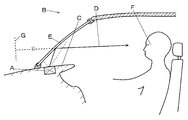
- the head-up display device A is provided at the upper part of the dashboard C of the vehicle B, and the display light (display image) D representing the generated display image is displayed on the windshield (windshield) E.
- It is a device that causes the vehicle driver F to visually recognize the virtual image G of the display image representing the vehicle information by reflecting. Thereby, the vehicle driver F can visually recognize the vehicle information without diverting his line of sight from the front.
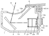
- the head-up display device A is provided at a location of the dashboard C facing the windshield E, and includes a display 2, a mirror member 3, and a blower 4 in the housing 1 as shown in FIG. 3. Yes.
- the casing 1 has a window portion 11 made of a transparent synthetic resin such as acrylic on the upper portion (front glass E side) so that display light D can be projected, and sunlight incident through the windshield E is displayed on the display 2.
- a storage space is formed by fitting together the light-shielding portion 12 having a wall portion 12a for preventing illumination of light and a holding portion 13 made of a metal material such as aluminum and holding the display 2 and the mirror member 3.
- a heat radiating part 13b made of a fin-shaped rib (rib shape) is formed on the outer surface of the holding base 13a for holding the indicator 2.
- the housing 1 can transfer the heat generated from the display 2 to the heat radiating portion 13b from the holding base 13a.
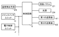
- the display 2 includes a liquid crystal panel 21, an optical filter 22, a fixing part 23, a light source 24, a temperature detection means 25, and a circuit board 26.
- the liquid crystal panel 21 is connected to a control circuit (control means) 5 provided in the housing 1, forms vehicle information such as the traveling speed of the vehicle B as a display image, and transmits light transmitted by the light source 24. In response, this display image can be projected onto the windshield E as display light D.
- vehicle information such as the traveling speed of the vehicle B as a display image
- the optical filter 22 is a member for efficiently irradiating the liquid crystal panel 21 with light from the light source 24, and an optical member such as a lenticular lens or a prism sheet can be applied. Further, as the optical filter 22, a diffusion plate, a lens array, or the like can be replaced or used in combination.
- the optical filter 22 is provided between the light source 24 and the liquid crystal panel 21, and has an effect of making it difficult to transfer heat to the liquid crystal panel 21 side by blocking heat (convection heat) generated by the light source 24.
- the fixing portion 23 is formed in a cylindrical shape with a light shielding property, and fixes the liquid crystal panel 21 and the optical filter 22 and forms a light guide space for guiding illumination light from the light source 24 to the liquid crystal panel 21.
- the fixing portion 23 is made of a metal material, and can efficiently transfer and dissipate heat so that the liquid crystal panel 21 does not exceed the heat-resistant temperature. Further, since the deformation due to temperature change is small compared to a synthetic resin, the liquid crystal panel This is advantageous for suppressing the positional deviation of 21.
- a light emitting diode can be applied, and a light source capable of high luminance output is applied in consideration of enlargement by a mirror member 3 to be described later and the amount of light transmitted through the windshield E.
- a plurality of light sources 24 are mounted on the circuit board 26 by applying surface-mounted chip components.
- the temperature detection means 25 detects the temperature environment of the display 2 that changes due to the temperature of the external atmosphere of the head-up display device A and the heat generated by electronic components such as sunlight and the light source 24.
- the temperature detection means 25 is a circuit configured using a thermistor whose resistance value varies with temperature, and outputs an electric signal having a voltage value corresponding to the temperature (resistance value) to the control circuit 5.
- the thermistor serving as a detection unit is mounted on the mounting surface of the light source 24 on the circuit board 26.
- the circuit board 26 can be a hard printed circuit board on which the light source 24 and the temperature detection means 25 are mounted, and is held in contact with the holding table 13a.
- the circuit board 26 uses a board made of a metal material and printed with an electrical insulating layer or a wiring pattern.
- seat which has the elasticity for heat-transferring efficiently, ensuring the contact area of the circuit board 26 and the holding stand 13a can also be provided between the circuit board 26 and the holding stand 13a.
- a concave mirror held by the holding unit 13 of the housing 1 can be applied, and it can be projected onto the windshield E through the window unit 11 by reflecting the display light D from the display device 2 while expanding it.
- the mirror member 3 has an actuator including a motor (not shown) and the like, and the angle of the reflecting surface of the mirror member 3 can be adjusted by drive control by the control circuit 5, and the windshield according to the viewpoint position of the vehicle driver F can be adjusted.
- the projection position onto E can be adjusted.
- the blower 4 As the blower 4, a cooling fan motor in which a fan that cools the head-up display device A and a motor that rotationally drives the head-up display device A by encouraging heat dissipation by an airflow can be applied. It is done. Further, in this case, the blower 4 is provided in the vicinity of the dashboard C in the upper portion of the side surface of the housing 1 and the first blower 41 provided so as to be opposed to the heat radiating portion 13b, and has a different direction from the first blower 41. And a second blower 42 that blows air, and is driven and controlled by the control circuit 5 based on different control signals.
- the blower 4 not only switches the rotation / stop of the fan according to the control signal, but can also rotate at different speeds.
- the blower 4 is held by the holding unit 13 via an elastic member, so that the vibration of the blower 4 is not easily transmitted to the display 2 side, and the heat of the holding unit 13 is not easily transmitted to the blower 4. It is possible to prevent problems such as thermal deformation.
- the control circuit 5 is mounted on a circuit board different from the circuit board 26 on which the light source 24 is mounted, and the liquid crystal panel 21 and the light source 24 are based on electric signals from the temperature detection means 25 and vehicle information input via a communication cable.
- a microcomputer for controlling the first and second blowers 41, 42 and the like can be applied.
- the control circuit 5 includes a threshold value and temporary calculation data, which will be described later, a storage unit for storing a predetermined program, an arithmetic processing unit for performing arithmetic processing based on input information and a predetermined program, and an input / output interface. Yes.
- the control circuit 5 displays the vehicle running speed, alarms, indicators, and the like on the display 2 based on vehicle information input through communication with the main switch unit H, the electronic control unit J, and various sensor units mounted on the vehicle. In addition to controlling the drive so that the air blower 4 is controlled, it is also used to control the blower 4 based on the temperature detection means 25.
- the control circuit 5 drives and controls the light source 24 and the liquid crystal panel 21 to start display output based on an operation signal from the main switch unit H of the vehicle, and projects the display light D.
- the control circuit 5 performs a determination process (step S ⁇ b> 1) for determining whether or not the first threshold value has been reached based on the electrical signal from the temperature detection means 25. .
- a determination process it is determined whether or not the temperature range is sufficient when the head-up display device A is operated by heat transfer or heat dissipation by the casing 1 including the heat radiating portion 13b without using the blower 4. Yes.
- the first threshold value can be set to a value (voltage value of an electric signal) corresponding to a temperature detected by the temperature detecting means 25 of 80 degrees Celsius, for example, an electronic component in the housing 1 of the head-up display device A, For example, it can be set so as to correspond to a temperature that sufficiently satisfies the temperature (heat-resistant temperature) allowed by the liquid crystal panel 21.
- the control circuit 5 operates the first blower 41 when the determination condition of step S1 is satisfied and the first threshold value is exceeded, that is, when the temperature reaches a temperature higher than the sufficient temperature range.
- a control signal for prompting to be generated is issued (step S2). Since the heat radiation effect by the heat radiating portion 13b is increased by the air blow by the first blower 41, the temperature rise of the head-up display device A including the display device 2 can be suppressed.
- step S1 when the determination condition of step S1 is not satisfied and the first threshold value is not exceeded, the control circuit 5 is not in a high temperature state and the transmission by the housing 1 including the heat radiating portion 13b is not performed. Assuming that heat and heat dissipation are sufficient and that the blower 4 is not required, a control signal that prompts the first and second blowers 41 and 42 to be in a stopped state is sent to the first and second blowers 41 and 42. It outputs to each (step S3, S6). By this process, it is possible to prevent unnecessary vibration and noise from being generated due to unnecessary rotational driving of the blower 4. Moreover, the operating time of the blower 4 can be suppressed, and the deterioration rate of the blower 4 itself can be slowed.
- the control circuit 5 determines whether or not the second threshold value has been reached based on the electrical signal from the temperature detecting means 25 in the operating state of the first blower 41 through the process of step S2. Processing (step S4) is performed.
- the second threshold can be set to a temperature higher than the temperature corresponding to the first threshold, for example, a value corresponding to 90 degrees Celsius.
- control circuit 5 determines whether or not the third threshold value corresponding to a higher temperature than the second threshold value is reached when the second threshold value is exceeded by the determination processing in step S4.
- a determination process for determining whether or not.
- the third threshold value for example, a value corresponding to the detected temperature of the temperature detecting means 25 corresponding to 100 degrees Celsius can be set. Note that if the second threshold value is not exceeded by the determination process in step S4, a control signal that prompts the second blower 42 to stop is output while the first blower 41 remains in the operating state. (Step S6).
- step S4 and S5 even if the first blower 41 is operating, it is determined whether the temperature has risen and has reached a high temperature range, and the degree of temperature has been determined.
- the control circuit 5 sets the second blower 42 so as to rotate the cooling fan at a rotational speed corresponding to this temperature range.
- Drive control is performed (steps S7 and S8).
- the 2nd air blower 42 is provided so that it may ventilate in the direction different from the 1st air blower 41, and in this case, the heat radiation part 13b vicinity in the dashboard C is ventilated along the surface of the housing
- the casing 1 can be cooled.
- the second blower 42 since the second blower 42 operates to move the air in contact with the dashboard C, the thermal influence from the dashboard C heated by sunlight irradiated through the windshield E can be reduced. .
- the control circuit 5 determines the rotational speed when the electrical signal from the temperature detecting means 25 is between the second threshold value and the third threshold value (step S7) by the determination processing in steps S4 and S5. However, the second blower 42 is controlled so as to increase the rotation speed when the third threshold value is exceeded (step S8) (strong wind operation). By changing the rotational speed of the second blower 42 based on the electrical signal from the temperature detection means 25, it is possible to suppress generation of noise that is larger than necessary.
- the control circuit 5 can also switch and control the rotational speed of the blower 4 from a low wind to a strong wind in multiple stages. In this case, it is difficult to notice changes during switching, such as the operating sound of the blower 4.
- the second blower 42 is different in operating conditions from the first blower 41 and has a shorter operation time than the first blower 41, the possibility of failure at the same time can be reduced, and the display of the head-up display device A can be reduced. There is an effect of keeping the quality long.
- working of a vehicle also has the said effect.
- the possibility of failure at the same time can be further reduced by using the blower 4 having different specifications such as heat resistant temperature, vibration resistance, and air volume.
- the fourth signal corresponding to the higher temperature of the electrical signal from the temperature detection means 25 It is determined whether or not the threshold value is reached (step S9). If the condition is satisfied, drive control is performed so as to reduce the luminance of the light source 24 (step S10). By reducing the output of the light source 24, the amount of heat generated is suppressed and each component such as the light source 24 acts so as not to reach an allowable temperature (heat-resistant temperature). For example, a value corresponding to 105 degrees Celsius close to the limit of the allowable temperature for operating the light source 24 is set as the fourth threshold value as the determination condition.
- the control circuit 5 prompts the output of the light source 24 so as to correspond to the brightness of the display light L desired by the vehicle driver F and the preset normal luminance when the determination condition of step S9 is not satisfied. Is performed (step S11).
- the blower 4 can be operated with an optimum air volume according to the detection result of the temperature detection means 25. Moreover, since the air blower 4 does not perform cooling at an operation or rotational speed higher than necessary, vibration and noise caused by the air blower 4 can be suppressed, so that a comfortable driving environment can be provided to the vehicle driver F. Moreover, power consumption for operating the blower 4 can be suppressed by reducing unnecessary operations. In addition, since each threshold value can provide hysteresis in the temperature increasing direction and the decreasing direction to reduce the frequency of switching the blown air amount according to each condition, it is difficult for the vehicle user to notice the operation of the blower 4.
- Such a head-up display device A for a vehicle is housed in the housing 1, and cools the display 2 by projecting display light D indicating vehicle information using illumination light from the light source 24.
- the head-up display device A can be cooled with an optimum air volume.
- the degree of freedom of the mounting position of the head-up display device A can be increased even when a large amount of exhaust heat space cannot be secured in various devices such as instruments and air conditioner ducts mounted in the dashboard. it can.
- the temperature detection means 25 which detects the temperature of the indicator 2 is provided, and the control circuit 5 respond
- the head-up display device A can be cooled with an optimal air volume.
- the housing 1 is provided between the blowers 41 and 42 and the display device 2, and the blowers 41 and 42 cool the display device 2 through the housing 1, thereby preventing the display from being influenced by the air blowing.
- the up display device A can be cooled.
- a housing 1 mounted on the upper part of the dashboard C of the vehicle B, a display 2 that is housed in the housing 1 and projects the display light D using illumination light from the light source 24, and a display
- the blower 4 provided with a fan for cooling the fan 2, the temperature detection means 25 for detecting the temperature of the display 2, and the control for drive control by changing the rotation speed of the blower 4 according to the detection signal from the temperature detection means 25.
- the vehicle head-up display device of the present invention has been described as an example in the configuration of the above-described embodiment, but the present invention is not limited to this, and the gist of the present invention is also in other configurations. It goes without saying that various improvements and design changes can be made without departing from the scope of the invention.
- the air in the housing 1 is moved.
- the display 20 such as the light source 240 can be cooled.
- the first and second blowers 410 and 420 are provided at different locations, and the second blower 420 moves the air between the light source 240 and the liquid crystal panel 210 to directly dissipate heat from the display device 20.
- the head-up display device A can be cooled by prompting and exhausting heat outside the housing 10.
- the first blower 410 is provided outside the housing 10, but the blower is provided on each of the intake side and the exhaust side of the air passage so that each blower is similar to the above-described embodiment.
- 410 and 420 can be operated under different conditions, and the same effect as the above-described embodiment can be obtained.
- the temperature detecting means 25 is disposed in the vicinity of the light source 24.
- the temperature can also be detected using a thermistor mounted on the liquid crystal panel 210.
- the liquid crystal panel Corresponding to the temperature of 210, the blowers 410 and 420 are driven and controlled under different temperature conditions, so that the same effect as the above-described embodiment can be obtained.
- the present invention relates to a head-up display device for a vehicle, and can be applied as, for example, a head-up display device mounted on a moving body including an automobile, a motorcycle, an agricultural machine, or a construction machine.
Abstract
Provided is a head-up display device that can be cooled at an optimal airflow rate. The head-up display device is provided with: a display unit (2) that is housed inside a case (1) and projects display light (D) for showing vehicle information by utilizing the illumination of light from light sources (24); multiple air blowers (41, 42) for cooling the display unit (2); and a control circuit (5) that performs drive control so as to switch between on and off states of the multiple air blowers (41, 42), respectively, in accordance with different conditions. In addition, the control circuit (5) performs the drive control so as to change the rotation speeds of the air blowers (4) in accordance with a detection signal from a temperature detection means (25) that detects a temperature of the display unit (2).
Description
本発明は、車両用ヘッドアップディスプレイ装置に関し、例えば、車両のウィンドシールドに表示像を投影するヘッドアップディスプレイ装置として好適である。
The present invention relates to a vehicle head-up display device, and is suitable, for example, as a head-up display device that projects a display image on a windshield of a vehicle.
従来より、車両の運転手が運転中に視線をほとんど動かさずに車両情報(速度、走行速度等)を読み取れるようにするため、車両のフロントガラス或いはコンバイナと称される半透過板に表示光を投影し、虚像を表示する車両用ヘッドアップディスプレイ装置が種々提案されており、例えば特許文献1に開示されている。車両用ヘッドアップディスプレイ装置は、透光性の窓部を備えたハウジングに液晶表示器及び反射鏡を収容したものであり、車両のダッシュボード内に配設される。
Conventionally, in order to enable a vehicle driver to read vehicle information (speed, travel speed, etc.) with little movement of the line of sight while driving, display light has been applied to a transflective plate called a windshield or combiner of the vehicle. Various vehicle head-up display devices that project and display a virtual image have been proposed. A vehicle head-up display device is a housing in which a liquid crystal display and a reflecting mirror are housed in a housing having a translucent window, and is disposed in a dashboard of the vehicle.
上述のようなヘッドアップディスプレイ装置には、液晶画面等に表示された画像をフロントガラスに投影するために、蛍光管または白熱電球、発光ダイオードなどの光源を適用している。
In the head-up display device as described above, a light source such as a fluorescent tube, an incandescent light bulb, or a light emitting diode is applied in order to project an image displayed on a liquid crystal screen or the like onto a windshield.
また、上述の車両用のヘッドアップディスプレイの場合は、昼間の明るい状況下で使用することが多いので、高輝度の得ることのできる光源を必要とする一方で、ヘッドアップディスプレイ装置の各種部品が耐熱温度を超えないようにする対策が必要となり、放熱フィンを設けたヒートシンクや冷却用ファンを備えている。
In the case of the above-mentioned head-up display for a vehicle, since it is often used in a daytime bright situation, a light source capable of obtaining high brightness is required, while various parts of the head-up display device are used. Measures must be taken so as not to exceed the heat-resistant temperature, and a heat sink and a cooling fan provided with heat radiation fins are provided.
しかしながら、上述した冷却用ファンは、送風量が小さいものを適用した場合には、例えば、高温環境下で光源を高輝度出力させるなどした際に、必要な冷却効果が得られない虞れがある。一方で充分な送風量を得るために大型ファンや回転速度の高いファンを適用した場合、冷却用ファンの作動にともなって余計な振動や雑音を発生してしまう虞れがあった。
However, when the cooling fan described above is applied with a small amount of blown air, for example, when a light source is output with high luminance in a high temperature environment, a necessary cooling effect may not be obtained. . On the other hand, when a large fan or a fan with a high rotation speed is applied in order to obtain a sufficient amount of air flow, there is a possibility that extra vibration and noise may be generated with the operation of the cooling fan.
そこで本願発明の目的は、上述した課題に着目し、最適な風量にて冷却できるヘッドアップディスプレイ装置を提供することにある。
Therefore, an object of the present invention is to provide a head-up display device capable of cooling with an optimum air volume, paying attention to the above-described problems.
本発明の車両用ヘッドアップディスプレイ装置は、
筐体内に収納され、光源からの照明光を利用して車両情報を示す表示像を投影する表示器と、
前記表示器を冷却する複数の送風機と、
それぞれ異なる条件によって前記複数の送風機の作動/停止状態を切り替えて駆動制御する制御手段と、
を備えることを特徴とする。 The vehicle head-up display device of the present invention includes:
A display that is housed in a housing and projects a display image indicating vehicle information using illumination light from a light source;
A plurality of blowers for cooling the indicator;
Control means for switching and controlling the operation / stop state of the plurality of fans according to different conditions,
It is characterized by providing.
また、前記表示器の温度を検出する温度検出手段を備え、
前記制御手段は、前記温度検出手段からの検出信号における異なるしきい値を前記条件として適用することを特徴とする。 In addition, a temperature detection means for detecting the temperature of the display,
The control means applies a different threshold value in the detection signal from the temperature detection means as the condition.
前記制御手段は、前記温度検出手段からの検出信号における異なるしきい値を前記条件として適用することを特徴とする。 In addition, a temperature detection means for detecting the temperature of the display,
The control means applies a different threshold value in the detection signal from the temperature detection means as the condition.
また、前記送風機と前記表示器との間に前記筐体を備え、
前記送風機は、前記筐体を介して前記表示器を冷却することを特徴とする。 In addition, the housing is provided between the blower and the indicator,
The blower cools the display through the housing.
前記送風機は、前記筐体を介して前記表示器を冷却することを特徴とする。 In addition, the housing is provided between the blower and the indicator,
The blower cools the display through the housing.
車両のダッシュボードの上部に搭載される筐体と、
この筐体内に収納され、光源からの照明光を利用して表示像を投影する表示器と、
前記表示器を冷却するファンを設ける送風機と、
前記表示器の温度を検出する温度検出手段と、
前記温度検出手段からの検出信号に応じて、前記ファンの回転速度を変えて駆動制御する制御手段と、
を備えることを特徴とする。 A chassis mounted on top of the vehicle dashboard,
A display that is housed in the housing and projects a display image using illumination light from a light source;
A blower provided with a fan for cooling the indicator;
Temperature detecting means for detecting the temperature of the indicator;
In accordance with a detection signal from the temperature detection means, a control means for controlling driving by changing the rotation speed of the fan;
It is characterized by providing.
本発明は、車両用ヘッドアップディスプレイ装置に関し、最適な風量にて装置を冷却できる。
The present invention relates to a head-up display device for a vehicle, and can cool the device with an optimum air volume.
以下、添付の図面に基づいて、本発明を自動車に搭載するヘッドアップディスプレイ装置に適用したものを実施形態として説明する。
Hereinafter, an embodiment in which the present invention is applied to a head-up display device mounted on an automobile will be described with reference to the accompanying drawings.
ヘッドアップディスプレイ装置Aは、図1,2に示すように、車両BのダッシュボードCの上部に設けられ、生成した表示画像を表す表示光(表示像)Dをフロントガラス(ウィンドシールド)Eで反射させることにより、車両運転者Fに車両情報を表す表示画像の虚像Gを視認させる装置である。これにより、車両運転者Fは、前方から視線を逸らさずに車両情報を視認できる。
As shown in FIGS. 1 and 2, the head-up display device A is provided at the upper part of the dashboard C of the vehicle B, and the display light (display image) D representing the generated display image is displayed on the windshield (windshield) E. It is a device that causes the vehicle driver F to visually recognize the virtual image G of the display image representing the vehicle information by reflecting. Thereby, the vehicle driver F can visually recognize the vehicle information without diverting his line of sight from the front.
また、ヘッドアップディスプレイ装置Aは、フロントガラスEに対向するダッシュボードCの箇所に設けられ、図3に示すよう、筐体1内に表示器2や、ミラー部材3、送風機4とを備えている。
The head-up display device A is provided at a location of the dashboard C facing the windshield E, and includes a display 2, a mirror member 3, and a blower 4 in the housing 1 as shown in FIG. 3. Yes.
筐体1は、表示光Dを投影できるように、上部(フロントガラスE側)にアクリル等の透明な合成樹脂からなる窓部11と、フロントガラスEを介して入射する太陽光が表示器2を照らさないための壁部12aを有する遮光部12と、アルミニウムなどの金属材料からなり、表示器2やミラー部材3を保持する保持部13とを嵌め合わせて収納空間を形成する。
The casing 1 has a window portion 11 made of a transparent synthetic resin such as acrylic on the upper portion (front glass E side) so that display light D can be projected, and sunlight incident through the windshield E is displayed on the display 2. A storage space is formed by fitting together the light-shielding portion 12 having a wall portion 12a for preventing illumination of light and a holding portion 13 made of a metal material such as aluminum and holding the display 2 and the mirror member 3.
なお、保持部13には、表示器2を保持する保持台13aの外側面に、突条のフィン形状(リブ形状)からなる放熱部13bが形成されている。筐体1は、表示器2から発せられる熱を保持台13aから放熱部13bへ伝熱できる。
In the holding part 13, a heat radiating part 13b made of a fin-shaped rib (rib shape) is formed on the outer surface of the holding base 13a for holding the indicator 2. The housing 1 can transfer the heat generated from the display 2 to the heat radiating portion 13b from the holding base 13a.
表示器2は、液晶パネル21と、光学フィルタ22と、固定部23と、光源24と、温度検出手段25と、回路基板26と、を設けている。
The display 2 includes a liquid crystal panel 21, an optical filter 22, a fixing part 23, a light source 24, a temperature detection means 25, and a circuit board 26.
液晶パネル21は、図4に示すように、筐体1に備える制御回路(制御手段)5に接続され、車両Bの走行速度などの車両情報を表示画像として形成し、光源24による透過照明を受けて、この表示画像を表示光DとしてフロントガラスEに投影できる。
As shown in FIG. 4, the liquid crystal panel 21 is connected to a control circuit (control means) 5 provided in the housing 1, forms vehicle information such as the traveling speed of the vehicle B as a display image, and transmits light transmitted by the light source 24. In response, this display image can be projected onto the windshield E as display light D.
光学フィルタ22は、光源24からの光を斑なく、効率よく液晶パネル21へ照射するための部材で、レンチキュラレンズやプリズムシートなどの光学部材を適用できる。また、光学フィルタ22として、拡散板やレンズアレイなど置き換え、または併用して適用することもできる。光学フィルタ22は、光源24と液晶パネル21との間に設けられ、光源24が発する熱(対流する熱)を遮ることで、液晶パネル21側に伝熱しにくくする作用もある。
The optical filter 22 is a member for efficiently irradiating the liquid crystal panel 21 with light from the light source 24, and an optical member such as a lenticular lens or a prism sheet can be applied. Further, as the optical filter 22, a diffusion plate, a lens array, or the like can be replaced or used in combination. The optical filter 22 is provided between the light source 24 and the liquid crystal panel 21, and has an effect of making it difficult to transfer heat to the liquid crystal panel 21 side by blocking heat (convection heat) generated by the light source 24.
固定部23は、遮光性で筒状に形成され、液晶パネル21や光学フィルタ22を固定するとともに、光源24からの照明光を液晶パネル21へ導くための導光空間を形成する。この場合、固定部23は、金属材料からなり、液晶パネル21が耐熱温度を超えないように効率よく伝熱や放熱でき、また、合成樹脂等に比べて温度変化による変形が小さいため、液晶パネル21の位置ずれを抑えるために有利である。
The fixing portion 23 is formed in a cylindrical shape with a light shielding property, and fixes the liquid crystal panel 21 and the optical filter 22 and forms a light guide space for guiding illumination light from the light source 24 to the liquid crystal panel 21. In this case, the fixing portion 23 is made of a metal material, and can efficiently transfer and dissipate heat so that the liquid crystal panel 21 does not exceed the heat-resistant temperature. Further, since the deformation due to temperature change is small compared to a synthetic resin, the liquid crystal panel This is advantageous for suppressing the positional deviation of 21.
光源24は、発光ダイオードを適用でき、後述するミラー部材3による拡大や、フロントガラスEでの透過光量分を考慮して、高輝度出力可能なものが適用される。この場合、光源24は、表面実装型のチップ部品を適用し、回路基板26に複数実装される。
As the light source 24, a light emitting diode can be applied, and a light source capable of high luminance output is applied in consideration of enlargement by a mirror member 3 to be described later and the amount of light transmitted through the windshield E. In this case, a plurality of light sources 24 are mounted on the circuit board 26 by applying surface-mounted chip components.
温度検出手段25は、ヘッドアップディスプレイ装置Aの外部雰囲気の温度や、太陽光線、光源24等の電子部品の発熱などによって変化する表示器2の温度環境を検出する。温度検出手段25は、温度よって抵抗値が変化するサーミスタを用いて構成される回路で、温度(抵抗値)に応じた電圧値を有する電気信号を、制御回路5に出力する。この場合、温度検出手段25は、光源24の温度に近い温度を検出するため、検出部となる該サーミスタが回路基板26における光源24の実装面に実装されている。
The temperature detection means 25 detects the temperature environment of the display 2 that changes due to the temperature of the external atmosphere of the head-up display device A and the heat generated by electronic components such as sunlight and the light source 24. The temperature detection means 25 is a circuit configured using a thermistor whose resistance value varies with temperature, and outputs an electric signal having a voltage value corresponding to the temperature (resistance value) to the control circuit 5. In this case, since the temperature detection means 25 detects a temperature close to the temperature of the light source 24, the thermistor serving as a detection unit is mounted on the mounting surface of the light source 24 on the circuit board 26.
回路基板26は、光源24や温度検出手段25を実装する硬質プリント基板を適用でき、保持台13aに接するように保持される。この場合、回路基板26は、光源24からの発熱を効率良く保持台13aに伝えるため、金属材料からなる基板に、電気絶縁層や配線パターンが印刷されたものを用いる。なお、回路基板26と保持台13aとの接触面積を確保しつつ効率よく伝熱するための弾性を有する伝熱シートを、回路基板26と保持台13aとの間に設けることもできる。
The circuit board 26 can be a hard printed circuit board on which the light source 24 and the temperature detection means 25 are mounted, and is held in contact with the holding table 13a. In this case, in order to efficiently transmit the heat generated from the light source 24 to the holding base 13a, the circuit board 26 uses a board made of a metal material and printed with an electrical insulating layer or a wiring pattern. In addition, the heat-transfer sheet | seat which has the elasticity for heat-transferring efficiently, ensuring the contact area of the circuit board 26 and the holding stand 13a can also be provided between the circuit board 26 and the holding stand 13a.
ミラー部材3は、筐体1の保持部13に保持される凹面鏡を適用でき、表示器2からの表示光Dを拡大しつつ反射することで、窓部11を介してフロントガラスEに投影できる。また、ミラー部材3は、図示しないモータ等からなるアクチュエータを有し、制御回路5による駆動制御によって、ミラー部材3の反射面の角度を調整でき、車両運転者Fの視点位置に応じたフロントガラスEへの投影位置を調整できる。
As the mirror member 3, a concave mirror held by the holding unit 13 of the housing 1 can be applied, and it can be projected onto the windshield E through the window unit 11 by reflecting the display light D from the display device 2 while expanding it. . Further, the mirror member 3 has an actuator including a motor (not shown) and the like, and the angle of the reflecting surface of the mirror member 3 can be adjusted by drive control by the control circuit 5, and the windshield according to the viewpoint position of the vehicle driver F can be adjusted. The projection position onto E can be adjusted.
送風機4は、気流によって放熱を促すことによってヘッドアップディスプレイ装置Aを冷却するファンとこれを回転駆動するモータとが一体に構成された冷却用ファンモータを適用でき、筐体1の複数箇所に設けられる。また、送風機4は、この場合、放熱部13b箇所に対向するように設けられる第1の送風機41と、筐体1の側面上部でダッシュボードC付近に設けられ、第1の送風機41と異なる向きに送風する第2の送風機42と、を設け、それぞれ別の制御信号に基づいて、制御回路5に駆動制御される。
As the blower 4, a cooling fan motor in which a fan that cools the head-up display device A and a motor that rotationally drives the head-up display device A by encouraging heat dissipation by an airflow can be applied. It is done. Further, in this case, the blower 4 is provided in the vicinity of the dashboard C in the upper portion of the side surface of the housing 1 and the first blower 41 provided so as to be opposed to the heat radiating portion 13b, and has a different direction from the first blower 41. And a second blower 42 that blows air, and is driven and controlled by the control circuit 5 based on different control signals.
なお、送風機4は、制御信号によって、ファンの回転/停止を切り替えるだけでなく、異なる速度にて回転することもできる。また、送風機4は、保持部13に弾性部材を介して保持させることで、送風機4の振動が表示器2側に伝わりにくくする他、保持部13の熱が送風機4に伝わりにくくして送風機4の熱変形等の不具合を防止できる。
Note that the blower 4 not only switches the rotation / stop of the fan according to the control signal, but can also rotate at different speeds. The blower 4 is held by the holding unit 13 via an elastic member, so that the vibration of the blower 4 is not easily transmitted to the display 2 side, and the heat of the holding unit 13 is not easily transmitted to the blower 4. It is possible to prevent problems such as thermal deformation.
制御回路5は、光源24を実装する回路基板26と異なる回路基板に実装され、温度検出手段25からの電気信号や通信ケーブルを介して入力される車両情報に基づいて、液晶パネル21や光源24、第1,第2の送風機41,42等を制御するマイクロコンピュータを適用できる。制御回路5は、後述するしきい値や一時的な演算データ、所定のプログラムを格納する記憶部、入力する情報や所定のプログラムに基づいて演算処理を行う演算処理部、入出力インターフェースを設けている。
The control circuit 5 is mounted on a circuit board different from the circuit board 26 on which the light source 24 is mounted, and the liquid crystal panel 21 and the light source 24 are based on electric signals from the temperature detection means 25 and vehicle information input via a communication cable. A microcomputer for controlling the first and second blowers 41, 42 and the like can be applied. The control circuit 5 includes a threshold value and temporary calculation data, which will be described later, a storage unit for storing a predetermined program, an arithmetic processing unit for performing arithmetic processing based on input information and a predetermined program, and an input / output interface. Yes.
なお、制御回路5は、車載されるメインスイッチユニットHや電子制御ユニットJ、各種センサユニットとの通信によって入力する車両情報に基づいて、車両の走行速度や警報やインジケータなどを表示器2に表示させるように駆動制御する他、温度検出手段25に基づく送風機4の制御を行うものとして兼用される。
The control circuit 5 displays the vehicle running speed, alarms, indicators, and the like on the display 2 based on vehicle information input through communication with the main switch unit H, the electronic control unit J, and various sensor units mounted on the vehicle. In addition to controlling the drive so that the air blower 4 is controlled, it is also used to control the blower 4 based on the temperature detection means 25.
次に、本発明の関する制御回路5の処理について図面を用いて説明する。
Next, processing of the control circuit 5 relating to the present invention will be described with reference to the drawings.
制御回路5は、車両のメインスイッチユニットHからの稼働信号に基づいて、表示出力を開始するように、光源24や液晶パネル21を駆動制御し、表示光Dを投影する。
The control circuit 5 drives and controls the light source 24 and the liquid crystal panel 21 to start display output based on an operation signal from the main switch unit H of the vehicle, and projects the display light D.
この際、制御回路5は、図5に示すように、温度検出手段25からの電気信号に基づいて、第1のしきい値に達しているか否かを判定する判定処理(ステップS1)を行う。この判定処理によって、送風機4を用いなくとも、放熱部13bを含む筐体1による伝熱や放熱によって、ヘッドアップディスプレイ装置Aを稼働するに際して、充分な温度域であるか否かを判定している。第1のしきい値は、温度検出手段25による検出温度が摂氏80度に相当する値(電気信号の電圧値)を設定でき、例えば、ヘッドアップディスプレイ装置Aの筐体1内の電子部品、例えば、液晶パネル21の許容する温度(耐熱温度)を充分に満たす温度に相当するように設定できる。
At this time, as shown in FIG. 5, the control circuit 5 performs a determination process (step S <b> 1) for determining whether or not the first threshold value has been reached based on the electrical signal from the temperature detection means 25. . With this determination process, it is determined whether or not the temperature range is sufficient when the head-up display device A is operated by heat transfer or heat dissipation by the casing 1 including the heat radiating portion 13b without using the blower 4. Yes. The first threshold value can be set to a value (voltage value of an electric signal) corresponding to a temperature detected by the temperature detecting means 25 of 80 degrees Celsius, for example, an electronic component in the housing 1 of the head-up display device A, For example, it can be set so as to correspond to a temperature that sufficiently satisfies the temperature (heat-resistant temperature) allowed by the liquid crystal panel 21.
制御回路5は、このステップS1の判定条件を満たし、第1のしきい値を超えた場合、即ち、前記充分な温度域よりも高温域に達した場合に、第1の送風機41を作動状態にするように促す制御信号を発する(ステップS2)。第1の送風機41による送風によって、放熱部13bによる放熱効果が高まるため、表示器2を含むヘッドアップディスプレイ装置Aの温度上昇を抑えることができる。
The control circuit 5 operates the first blower 41 when the determination condition of step S1 is satisfied and the first threshold value is exceeded, that is, when the temperature reaches a temperature higher than the sufficient temperature range. A control signal for prompting to be generated is issued (step S2). Since the heat radiation effect by the heat radiating portion 13b is increased by the air blow by the first blower 41, the temperature rise of the head-up display device A including the display device 2 can be suppressed.
また、制御回路5は、ステップS1の判定条件を満たさず、第1のしきい値を超えない場合には、ヘッドアップディスプレイ装置Aが高温状態でなく、放熱部13bを含む筐体1による伝熱や放熱で充分であり、送風機4を必要としないとみなして、第1,第2の送風機41,42を停止状態にするように促す制御信号を、第1,第2の送風機41,42それぞれに出力する(ステップS3,S6)。この処理によって、不要な送風機4の回転駆動によって、余計な振動や雑音が発生してしまうことを抑止できる。また、送風機4の稼働時間を抑えて、送風機4自体の劣化速度を遅くできる。
In addition, when the determination condition of step S1 is not satisfied and the first threshold value is not exceeded, the control circuit 5 is not in a high temperature state and the transmission by the housing 1 including the heat radiating portion 13b is not performed. Assuming that heat and heat dissipation are sufficient and that the blower 4 is not required, a control signal that prompts the first and second blowers 41 and 42 to be in a stopped state is sent to the first and second blowers 41 and 42. It outputs to each (step S3, S6). By this process, it is possible to prevent unnecessary vibration and noise from being generated due to unnecessary rotational driving of the blower 4. Moreover, the operating time of the blower 4 can be suppressed, and the deterioration rate of the blower 4 itself can be slowed.
制御回路5は、ステップS2の処理を経て、第1の送風機41の作動状態において、温度検出手段25からの電気信号に基づいて、第2のしきい値に達しているか否かを判定する判定処理(ステップS4)を行う。第2のしきい値は、第1のしきい値に相当する温度よりも高温、例えば、摂氏90度に相当する値を設定できる。
The control circuit 5 determines whether or not the second threshold value has been reached based on the electrical signal from the temperature detecting means 25 in the operating state of the first blower 41 through the process of step S2. Processing (step S4) is performed. The second threshold can be set to a temperature higher than the temperature corresponding to the first threshold, for example, a value corresponding to 90 degrees Celsius.
また、制御回路5は、このステップS4の判定処理によって、第2のしきい値を超えた場合、第2のしきい値よりも更に高温に相当する第3のしきい値に達しているか否かを判定する判定処理(ステップS5)を行う。第3のしきい値は、例えば、温度検出手段25の検出温度が摂氏100度に相当する値を設定できる。なお、ステップS4の判定処理によって、第2のしきい値を超えていない場合には、第1の送風機41を作動状態としたまま、第2の送風機42を停止させるように促す制御信号を出力する(ステップS6)。
Further, the control circuit 5 determines whether or not the third threshold value corresponding to a higher temperature than the second threshold value is reached when the second threshold value is exceeded by the determination processing in step S4. A determination process (step S5) for determining whether or not. As the third threshold value, for example, a value corresponding to the detected temperature of the temperature detecting means 25 corresponding to 100 degrees Celsius can be set. Note that if the second threshold value is not exceeded by the determination process in step S4, a control signal that prompts the second blower 42 to stop is output while the first blower 41 remains in the operating state. (Step S6).
上記ステップS4,S5の判定処理によって、第1の送風機41が作動中であっても、温度上昇し更に高温域に達したか否かを判定するとともに、温度の度合いを判定している。制御回路5は、第2のしきい値,または第3のしきい値を超えた場合には、この温度域に応じた回転速度によって、冷却用ファンを回転するように第2の送風機42を駆動制御する(ステップS7,S8)。
In the determination processing in steps S4 and S5, even if the first blower 41 is operating, it is determined whether the temperature has risen and has reached a high temperature range, and the degree of temperature has been determined. When the second threshold value or the third threshold value is exceeded, the control circuit 5 sets the second blower 42 so as to rotate the cooling fan at a rotational speed corresponding to this temperature range. Drive control is performed (steps S7 and S8).
なお、第2の送風機42は、第1の送風機41と異なる向きに送風するように設けられ、この場合、筐体1の面に沿って送風することで、ダッシュボードC内における放熱部13b付近の熱溜まりを排除するように作用し、筐体1を冷却できる。また、この場合、第2の送風機42は、作動することでダッシュボードCに接する空気を動かすため、フロントガラスEを介して照射される太陽光によって熱せられるダッシュボードCからの熱影響も低減できる。
In addition, the 2nd air blower 42 is provided so that it may ventilate in the direction different from the 1st air blower 41, and in this case, the heat radiation part 13b vicinity in the dashboard C is ventilated along the surface of the housing | casing 1. Thus, the casing 1 can be cooled. In this case, since the second blower 42 operates to move the air in contact with the dashboard C, the thermal influence from the dashboard C heated by sunlight irradiated through the windshield E can be reduced. .
制御回路5は、上記ステップS4,S5の判定処理によって、温度検出手段25からの電気信号が第2のしきい値と第3のしきい値との間の場合(ステップS7)の回転速度よりも、第3のしきい値を超えた場合(ステップS8)の回転速度が大きくなるように第2の送風機42を制御する(強風作動)。温度検出手段25からの電気信号に基づいて、第2の送風機42の回転速度を変えることによって、必要以上に大きな雑音の発生を抑えることができる。なお、制御回路5は、送風機4の回転速度を弱風から強風まで多段階に切り替え制御することもでき、この場合、送風機4の作動音等、切り替え時の変化が気付きにくくなる。
The control circuit 5 determines the rotational speed when the electrical signal from the temperature detecting means 25 is between the second threshold value and the third threshold value (step S7) by the determination processing in steps S4 and S5. However, the second blower 42 is controlled so as to increase the rotation speed when the third threshold value is exceeded (step S8) (strong wind operation). By changing the rotational speed of the second blower 42 based on the electrical signal from the temperature detection means 25, it is possible to suppress generation of noise that is larger than necessary. The control circuit 5 can also switch and control the rotational speed of the blower 4 from a low wind to a strong wind in multiple stages. In this case, it is difficult to notice changes during switching, such as the operating sound of the blower 4.
また、第2の送風機42は、第1の送風機41と作動条件が異なり、第1の送風機41よりも稼働時間が短くなるため、同時に故障する可能性を低減でき、ヘッドアップディスプレイ装置Aの表示品位を長く保つ効果がある。また、複数の送風機4において、配置や向きが異なることで、各送風機4の温度環境や車両の走行にともなう振動方向に違いが生じることも、前記効果を奏することになる。加えて、耐熱温度、耐振動、風量など異なる仕様の送風機4を用いることによって、同時に故障する可能性を更に低減できる。
Moreover, since the second blower 42 is different in operating conditions from the first blower 41 and has a shorter operation time than the first blower 41, the possibility of failure at the same time can be reduced, and the display of the head-up display device A can be reduced. There is an effect of keeping the quality long. Moreover, in the some air blower 4, when the arrangement | positioning and direction differ, the difference in the temperature environment of each air blower 4 and the vibration direction accompanying driving | running | working of a vehicle also has the said effect. In addition, the possibility of failure at the same time can be further reduced by using the blower 4 having different specifications such as heat resistant temperature, vibration resistance, and air volume.
制御回路5は、第1の送風機41とともに、第2の送風機42を高い回転数で作動させた状態であっても、温度検出手段25からの電気信号が更に高い温度に相当する第4のしきい値に達するか否かを判定(ステップS9)し、条件を満たす場合には、光源24の輝度を低減するように駆動制御する(ステップS10)。光源24の出力を低減することで、発熱量を抑え光源24等の各部品が許容温度(耐熱温度)に達しないように作用する。例えば、判定条件となる第4のしきい値として、光源24が作動するための許容温度の限界に近い摂氏105度に相当する値が設定される。
Even if the control circuit 5 is in a state in which the second blower 42 is operated at a high rotational speed together with the first blower 41, the fourth signal corresponding to the higher temperature of the electrical signal from the temperature detection means 25. It is determined whether or not the threshold value is reached (step S9). If the condition is satisfied, drive control is performed so as to reduce the luminance of the light source 24 (step S10). By reducing the output of the light source 24, the amount of heat generated is suppressed and each component such as the light source 24 acts so as not to reach an allowable temperature (heat-resistant temperature). For example, a value corresponding to 105 degrees Celsius close to the limit of the allowable temperature for operating the light source 24 is set as the fourth threshold value as the determination condition.
なお、制御回路5は、ステップS9の判定条件を満たさない場合に、車両運転者Fが所望する表示光Lの明るさや予め設定された通常輝度に対応するように、光源24の出力を促す処理を行う(ステップS11)。
The control circuit 5 prompts the output of the light source 24 so as to correspond to the brightness of the display light L desired by the vehicle driver F and the preset normal luminance when the determination condition of step S9 is not satisfied. Is performed (step S11).
上述した処理手順を繰り返すことによって、温度検出手段25の検出結果に応じた最適な風量にて送風機4を作動させることができる。また、送風機4は、必要以上の作動や回転速度にて冷却を行わないため、送風機4による振動や雑音を抑えることができるため、車両運転者Fに快適な運転環境を提供できる。また、不要な作動を低減することで、送風機4を作動するための電力消費を抑えることができる。なお、各しきい値は、温度の上昇方向と下降方向とでヒステリシスを設けることによって、各条件による送風量の切り替わり頻度を低減できるため、車両利用者に送風機4を作動を気付きにくくできる。
By repeating the above-described processing procedure, the blower 4 can be operated with an optimum air volume according to the detection result of the temperature detection means 25. Moreover, since the air blower 4 does not perform cooling at an operation or rotational speed higher than necessary, vibration and noise caused by the air blower 4 can be suppressed, so that a comfortable driving environment can be provided to the vehicle driver F. Moreover, power consumption for operating the blower 4 can be suppressed by reducing unnecessary operations. In addition, since each threshold value can provide hysteresis in the temperature increasing direction and the decreasing direction to reduce the frequency of switching the blown air amount according to each condition, it is difficult for the vehicle user to notice the operation of the blower 4.
斯かる車両用ヘッドアップディスプレイ装置Aは、筐体1内に収納され、光源24からの照明光を利用して車両情報を示す表示光Dを投影する表示器2と、表示器2を冷却する複数の送風機41,42と、それぞれ異なる条件によって複数の送風機41,42の作動/停止状態を切り替えて駆動制御する制御回路5と、を備える。
Such a head-up display device A for a vehicle is housed in the housing 1, and cools the display 2 by projecting display light D indicating vehicle information using illumination light from the light source 24. A plurality of blowers 41 and 42 and a control circuit 5 that controls driving by switching the operation / stop state of the blowers 41 and 42 under different conditions.
従って、最適な風量にて冷却できるヘッドアップディスプレイ装置Aとなる。また、ダッシュボード内に搭載される計器や空気調和機用ダクトなど各種装置にて、排熱スペースを大きく確保できない場合であっても、ヘッドアップディスプレイ装置Aの搭載位置の自由度を高めることができる。
Therefore, the head-up display device A can be cooled with an optimum air volume. In addition, the degree of freedom of the mounting position of the head-up display device A can be increased even when a large amount of exhaust heat space cannot be secured in various devices such as instruments and air conditioner ducts mounted in the dashboard. it can.
また、表示器2の温度を検出する温度検出手段25を備え、制御回路5は、温度検出手段25からの検出信号における異なるしきい値を前記条件として適用することによって、温度条件に対応して、最適な風量にて冷却できるヘッドアップディスプレイ装置Aとなる。
Moreover, the temperature detection means 25 which detects the temperature of the indicator 2 is provided, and the control circuit 5 respond | corresponds to temperature conditions by applying the different threshold value in the detection signal from the temperature detection means 25 as said conditions. The head-up display device A can be cooled with an optimal air volume.
また、送風機41,42と表示器2との間に筐体1を備え、送風機41,42は、筐体1を介して表示器2を冷却することによって、送風による表示影響を及ぼすことなくヘッドアップディスプレイ装置Aを冷却できる。
Further, the housing 1 is provided between the blowers 41 and 42 and the display device 2, and the blowers 41 and 42 cool the display device 2 through the housing 1, thereby preventing the display from being influenced by the air blowing. The up display device A can be cooled.
また、車両BのダッシュボードCの上部に搭載される筐体1と、この筐体1内に収納され、光源24からの照明光を利用して表示光Dを投影する表示器2と、表示器2を冷却するファンを設ける送風機4と、表示器2の温度を検出する温度検出手段25と、温度検出手段25からの検出信号に応じて、送風機4の回転速度を変えて駆動制御する制御回路5と、を備えることによって、最適な風量にて冷却できるヘッドアップディスプレイ装置Aとなる。
Further, a housing 1 mounted on the upper part of the dashboard C of the vehicle B, a display 2 that is housed in the housing 1 and projects the display light D using illumination light from the light source 24, and a display The blower 4 provided with a fan for cooling the fan 2, the temperature detection means 25 for detecting the temperature of the display 2, and the control for drive control by changing the rotation speed of the blower 4 according to the detection signal from the temperature detection means 25. By providing the circuit 5, the head-up display device A that can be cooled with an optimum air volume is obtained.
なお、本発明の車両用ヘッドアップディスプレイ装置を上述した実施形態の構成にて例に挙げて説明したが、本発明はこれに限定されるものではなく、他の構成においても、本発明の要旨を逸脱しない範囲において種々の改良、並びに設計の変更が可能なことは勿論である。
The vehicle head-up display device of the present invention has been described as an example in the configuration of the above-described embodiment, but the present invention is not limited to this, and the gist of the present invention is also in other configurations. It goes without saying that various improvements and design changes can be made without departing from the scope of the invention.
例えば、上述した実施形態にあっては、複数の送風機4を筐体1の外側に設けるものを例にあげて説明したが、図7に示すように、筐体1内の空気を移動させることで光源240等の表示器20を冷却するように構成できる。この場合、第1,第2の送風機410,420を別箇所に設けており、第2の送風機420は、光源240と液晶パネル210との間の空気を動かして、直接表示器20の放熱を促すとともに、筐体10外へ排熱することでヘッドアップディスプレイ装置Aを冷却できる。
For example, in the above-described embodiment, an example in which a plurality of blowers 4 are provided outside the housing 1 has been described. However, as shown in FIG. 7, the air in the housing 1 is moved. Thus, the display 20 such as the light source 240 can be cooled. In this case, the first and second blowers 410 and 420 are provided at different locations, and the second blower 420 moves the air between the light source 240 and the liquid crystal panel 210 to directly dissipate heat from the display device 20. The head-up display device A can be cooled by prompting and exhausting heat outside the housing 10.
なお、この場合、通気路の出入口に通気可能な防塵フィルタ60を備えることによって、装置A内に埃等が入らないようにするとともに、第2の送風機420の発する雑音が装置A外へ漏れる量を低減できる。また、ミラー部材30として、凹面鏡310だけでなく、赤外線を透過し可視光を反射する光学薄膜をつけた平面ミラー(コールドミラー)320を設けることで、太陽光の入射による表示器20の発熱を抑え、発熱箇所を表示器20以外の耐熱性の高い箇所に分散して効率よく熱対策することもできる。
In this case, by providing a dustproof filter 60 that can be ventilated at the entrance / exit of the ventilation path, dust and the like are prevented from entering the apparatus A, and the amount of noise generated by the second blower 420 leaks out of the apparatus A. Can be reduced. Further, not only the concave mirror 310 but also a flat mirror (cold mirror) 320 with an optical thin film that transmits infrared rays and reflects visible light is provided as the mirror member 30, so that the display 20 generates heat due to the incidence of sunlight. It is possible to suppress the heat generation and disperse the heat generation places to places with high heat resistance other than the display unit 20 to efficiently take measures against heat.
また、図6では、第1の送風機410を筐体10外に設けるものを示したが、送風機を通気路の吸気側と排気側にそれぞれ設けて、上述した実施形態と同様に、それぞれの送風機410,420を異なる条件にて作動させることもでき、上述した実施形態と同様の効果が得られる。
In FIG. 6, the first blower 410 is provided outside the housing 10, but the blower is provided on each of the intake side and the exhaust side of the air passage so that each blower is similar to the above-described embodiment. 410 and 420 can be operated under different conditions, and the same effect as the above-described embodiment can be obtained.
また、上述した実施形態では、温度検出手段25を光源24の近傍に配置したものを示したが、液晶パネル210に実装されるサーミスタを用いて、温度検出することもでき、この場合、液晶パネル210の温度にも対応して、送風機410,420をそれぞれ異なる温度条件で駆動制御することで、上述した実施形態と同様の効果を得ることができる。
In the above-described embodiment, the temperature detecting means 25 is disposed in the vicinity of the light source 24. However, the temperature can also be detected using a thermistor mounted on the liquid crystal panel 210. In this case, the liquid crystal panel Corresponding to the temperature of 210, the blowers 410 and 420 are driven and controlled under different temperature conditions, so that the same effect as the above-described embodiment can be obtained.
本発明は、車両用ヘッドアップディスプレイ装置に関し、例えば、自動車やオートバイ、あるいは農業機械や建設機械を備えた移動体に搭載されるヘッドアップディスプレイ装置として適用できる。
The present invention relates to a head-up display device for a vehicle, and can be applied as, for example, a head-up display device mounted on a moving body including an automobile, a motorcycle, an agricultural machine, or a construction machine.
1 筐体
11 窓部
12 遮光部
12a 壁部
13 保持部
13a 保持台
13b 放熱部
2 表示器
21 液晶パネル
22 光学フィルタ
23 固定部
24 光源
25 温度検出手段
26 回路基板
3 ミラー部材
4 送風機
41 第1の送風機
42 第2の送風機
5 制御回路(制御手段)
A ヘッドアップディスプレイ装置
B 車両
C ダッシュボード
D 表示光
E フロントガラス
F 車両運転者
G 虚像
H メインスイッチユニット
J 電子制御ユニット DESCRIPTION OFSYMBOLS 1 Housing | casing 11 Window part 12 Light-shielding part 12a Wall part 13 Holding | maintenance part 13a Holding stand 13b Heat radiation part 2 Display 21 Liquid crystal panel 22 Optical filter 23 Fixing part 24 Light source 25 Temperature detection means 26 Circuit board 3 Mirror member 4 Blower 41 1st Blower 42 Second blower 5 Control circuit (control means)
A Head-up display device B Vehicle C Dashboard D Display light E Windshield F Vehicle driver G Virtual image H Main switch unit J Electronic control unit
11 窓部
12 遮光部
12a 壁部
13 保持部
13a 保持台
13b 放熱部
2 表示器
21 液晶パネル
22 光学フィルタ
23 固定部
24 光源
25 温度検出手段
26 回路基板
3 ミラー部材
4 送風機
41 第1の送風機
42 第2の送風機
5 制御回路(制御手段)
A ヘッドアップディスプレイ装置
B 車両
C ダッシュボード
D 表示光
E フロントガラス
F 車両運転者
G 虚像
H メインスイッチユニット
J 電子制御ユニット DESCRIPTION OF
A Head-up display device B Vehicle C Dashboard D Display light E Windshield F Vehicle driver G Virtual image H Main switch unit J Electronic control unit
Claims (4)
- 筐体内に収納され、光源からの照明光を利用して車両情報を示す表示像を投影する表示器と、
前記表示器を冷却する複数の送風機と、
それぞれ異なる条件によって前記複数の送風機の作動/停止状態を切り替えて駆動制御する制御手段と、
を備えることを特徴とする車両用ヘッドアップディスプレイ装置。 A display that is housed in a housing and projects a display image indicating vehicle information using illumination light from a light source;
A plurality of blowers for cooling the indicator;
Control means for switching and controlling the operation / stop state of the plurality of fans according to different conditions,
A vehicle head-up display device. - 前記表示器の温度を検出する温度検出手段を備え、
前記制御手段は、前記温度検出手段からの検出信号における異なるしきい値を前記条件として適用することを特徴とする請求項1に記載の車両用ヘッドアップディスプレイ装置。 Temperature detecting means for detecting the temperature of the indicator,
The vehicle head-up display device according to claim 1, wherein the control unit applies a different threshold value in a detection signal from the temperature detection unit as the condition. - 前記送風機と前記表示器との間に前記筐体を備え、
前記送風機は、前記筐体を介して前記表示器を冷却することを特徴とする請求項1に記載の車両用ヘッドアップディスプレイ装置。 The housing is provided between the blower and the indicator,
The vehicle head-up display device according to claim 1, wherein the blower cools the display through the housing. - 車両のダッシュボードの上部に搭載される筐体と、
この筐体内に収納され、光源からの照明光を利用して表示像を投影する表示器と、
前記表示器を冷却するファンを設ける送風機と、
前記表示器の温度を検出する温度検出手段と、
前記温度検出手段からの検出信号に応じて、前記ファンの回転速度を変えて駆動制御する制御手段と、
を備えることを特徴とする車両用ヘッドアップディスプレイ装置。 A chassis mounted on top of the vehicle dashboard,
A display that is housed in the housing and projects a display image using illumination light from a light source;
A blower provided with a fan for cooling the indicator;
Temperature detecting means for detecting the temperature of the indicator;
In accordance with a detection signal from the temperature detection means, a control means for controlling driving by changing the rotation speed of the fan;
A vehicle head-up display device.
Applications Claiming Priority (2)
| Application Number | Priority Date | Filing Date | Title |
|---|---|---|---|
| JP2015-012936 | 2015-01-27 | ||
| JP2015012936A JP2016137779A (en) | 2015-01-27 | 2015-01-27 | Vehicular head-up display system |
Publications (1)
| Publication Number | Publication Date |
|---|---|
| WO2016121269A1 true WO2016121269A1 (en) | 2016-08-04 |
Family
ID=56542902
Family Applications (1)
| Application Number | Title | Priority Date | Filing Date |
|---|---|---|---|
| PCT/JP2015/085759 WO2016121269A1 (en) | 2015-01-27 | 2015-12-22 | Head-up display device for vehicle |
Country Status (2)
| Country | Link |
|---|---|
| JP (1) | JP2016137779A (en) |
| WO (1) | WO2016121269A1 (en) |
Cited By (4)
| Publication number | Priority date | Publication date | Assignee | Title |
|---|---|---|---|---|
| EP3521886A1 (en) * | 2018-02-05 | 2019-08-07 | Valeo Comfort and Driving Assistance | Head-up display for a motor vehicle |
| CN110116607A (en) * | 2018-02-05 | 2019-08-13 | 丰田自动车株式会社 | Vehicle light-shielding structure |
| EP3757643A1 (en) * | 2019-06-28 | 2020-12-30 | Valeo Comfort and Driving Assistance | Head-up display |
| WO2022250033A1 (en) * | 2021-05-25 | 2022-12-01 | 日本精機株式会社 | Head-up display device |
Families Citing this family (3)
| Publication number | Priority date | Publication date | Assignee | Title |
|---|---|---|---|---|
| JP2019142276A (en) * | 2018-02-16 | 2019-08-29 | アルパイン株式会社 | Projection device and head-up display device with use of projection device |
| JP7354804B2 (en) * | 2019-12-02 | 2023-10-03 | 株式会社デンソー | Vehicle display device |
| JP7032003B2 (en) * | 2020-03-10 | 2022-03-08 | 矢崎総業株式会社 | Display device for vehicles |
Citations (4)
| Publication number | Priority date | Publication date | Assignee | Title |
|---|---|---|---|---|
| JP2003025872A (en) * | 2001-07-13 | 2003-01-29 | Honda Motor Co Ltd | Head up display device for vehicle |
| JP2005148658A (en) * | 2003-11-19 | 2005-06-09 | Nippon Seiki Co Ltd | Display device |
| JP2009260135A (en) * | 2008-04-18 | 2009-11-05 | Mitsubishi Electric Corp | Cooling fan control method for vehicle-mounted information equipment |
| JP2014195218A (en) * | 2013-03-29 | 2014-10-09 | Funai Electric Co Ltd | Projector and head-up display device |
Family Cites Families (1)
| Publication number | Priority date | Publication date | Assignee | Title |
|---|---|---|---|---|
| JP5388394B2 (en) * | 2001-05-31 | 2014-01-15 | キヤノン株式会社 | Projection type image display device |
-
2015
- 2015-01-27 JP JP2015012936A patent/JP2016137779A/en active Pending
- 2015-12-22 WO PCT/JP2015/085759 patent/WO2016121269A1/en active Application Filing
Patent Citations (4)
| Publication number | Priority date | Publication date | Assignee | Title |
|---|---|---|---|---|
| JP2003025872A (en) * | 2001-07-13 | 2003-01-29 | Honda Motor Co Ltd | Head up display device for vehicle |
| JP2005148658A (en) * | 2003-11-19 | 2005-06-09 | Nippon Seiki Co Ltd | Display device |
| JP2009260135A (en) * | 2008-04-18 | 2009-11-05 | Mitsubishi Electric Corp | Cooling fan control method for vehicle-mounted information equipment |
| JP2014195218A (en) * | 2013-03-29 | 2014-10-09 | Funai Electric Co Ltd | Projector and head-up display device |
Cited By (5)
| Publication number | Priority date | Publication date | Assignee | Title |
|---|---|---|---|---|
| EP3521886A1 (en) * | 2018-02-05 | 2019-08-07 | Valeo Comfort and Driving Assistance | Head-up display for a motor vehicle |
| FR3077650A1 (en) * | 2018-02-05 | 2019-08-09 | Valeo Comfort And Driving Assistance | HIGH HEAD DISPLAY FOR MOTOR VEHICLE |
| CN110116607A (en) * | 2018-02-05 | 2019-08-13 | 丰田自动车株式会社 | Vehicle light-shielding structure |
| EP3757643A1 (en) * | 2019-06-28 | 2020-12-30 | Valeo Comfort and Driving Assistance | Head-up display |
| WO2022250033A1 (en) * | 2021-05-25 | 2022-12-01 | 日本精機株式会社 | Head-up display device |
Also Published As
| Publication number | Publication date |
|---|---|
| JP2016137779A (en) | 2016-08-04 |
Similar Documents
| Publication | Publication Date | Title |
|---|---|---|
| WO2016121269A1 (en) | Head-up display device for vehicle | |
| JP6278155B2 (en) | Head-up display device | |
| JP6300012B2 (en) | Head-up display device, cooling system for head-up display device | |
| KR102397389B1 (en) | How to cool a full display mirror | |
| JP5189804B2 (en) | Projector device | |
| JP2007316319A (en) | Projector | |
| US20190182994A1 (en) | Head up display cooling | |
| EP3528043B1 (en) | Projector and head-up display device including projector | |
| JP2014153578A (en) | Head-up display | |
| JP2014146742A (en) | Head-up display | |
| JP2007069771A (en) | Head-up display device for vehicle | |
| JP2010167830A (en) | Vehicular head-up display device | |
| JP6286569B2 (en) | Projection display device and heat dissipation method | |
| JP2012222112A (en) | Display unit, and heat dissipation method thereof | |
| US11612085B2 (en) | Vehicular display device | |
| JP2005148658A (en) | Display device | |
| WO2016163078A1 (en) | Display device | |
| JP2015022020A (en) | Projection optical device and image projection device | |
| JP7474028B2 (en) | Head-up display | |
| KR100598943B1 (en) | Rear view mirror with display panel | |
| WO2017010395A1 (en) | Air-blowing device | |
| JPH02253290A (en) | On-vehicle liquid crystal display device | |
| JP2013142838A (en) | Imaging apparatus | |
| KR20220046785A (en) | Head-UP Display for Vehicle And Control Method Therefor | |
| WO2020170495A1 (en) | Head-up display |
Legal Events
| Date | Code | Title | Description |
|---|---|---|---|
| 121 | Ep: the epo has been informed by wipo that ep was designated in this application |
Ref document number: 15880161 Country of ref document: EP Kind code of ref document: A1 |
|
| NENP | Non-entry into the national phase |
Ref country code: DE |
|
| 122 | Ep: pct application non-entry in european phase |
Ref document number: 15880161 Country of ref document: EP Kind code of ref document: A1 |