JP2015022020A - Projection optical device and image projection device - Google Patents
Projection optical device and image projection device Download PDFInfo
- Publication number
- JP2015022020A JP2015022020A JP2013147860A JP2013147860A JP2015022020A JP 2015022020 A JP2015022020 A JP 2015022020A JP 2013147860 A JP2013147860 A JP 2013147860A JP 2013147860 A JP2013147860 A JP 2013147860A JP 2015022020 A JP2015022020 A JP 2015022020A
- Authority
- JP
- Japan
- Prior art keywords
- projection
- image
- projection optical
- heat
- unit
- Prior art date
- Legal status (The legal status is an assumption and is not a legal conclusion. Google has not performed a legal analysis and makes no representation as to the accuracy of the status listed.)
- Pending
Links
Images


Abstract
Description
本発明は、画像をスクリーン等の投射面に投射する投射光学装置及び画像投射装置に関するものである。 The present invention relates to a projection optical apparatus and an image projection apparatus that project an image onto a projection surface such as a screen.
従来から、パソコンやビデオカメラ等からの画像データを基に、光源から出射される光を用いて画像生成部により画像を生成する。その画像を、レンズ及びミラーなどの複数の光学素子、および、複数枚の投射レンズを有する投射レンズ群の投射光学装置によってスクリーン等の投射面に投射して表示する画像投射装置が知られている。画像生成部は、DMD(Digital Mirror Device)を備えている。投射レンズ群は、投射レンズ保持部のレンズホルダによって保持されている。 Conventionally, based on image data from a personal computer, a video camera or the like, an image is generated by an image generation unit using light emitted from a light source. There is known an image projection apparatus that projects and displays the image on a projection surface such as a screen by a projection optical device of a projection lens group having a plurality of optical elements such as a lens and a mirror and a plurality of projection lenses. . The image generation unit includes a DMD (Digital Mirror Device). The projection lens group is held by the lens holder of the projection lens holding unit.
特許文献1には、光源からの白色光をカラーホイールによってRGBに分光されて画像生成部のDMDへ導かれ、DMDによって変調信号に応じて画像が生成され、その画像を投射光学装置としての投射光学部の投射レンズ群で拡大投射する画像投射装置が記載されている。
In
従来の画像投射装置における投射光学部の一例を、図を用いて以下に説明する。
図12は、従来の画像投射装置の投射光学部100までの光路の様子を示す概略斜視図である。不図示のカラーホイールにより時分割でR(レッド),G(グリーン),B(ブルー)の光に分離された不図示の光源からの光L1が、ライトトンネル101へ入射する。ライトトンネル101は、四角筒形状であり、その内周面が鏡面となっている。ライトトンネル101の入射面に対して角度を持って入射した光が、ライトトンネル101内周面で複数回反射することにより均一な面光源となって、ライトトンネル101から2枚のリレーレンズ102へ向けて出射する。ライトトンネル101を出射した光は、2枚のリレーレンズ102を透過し、平面ミラー103、凹面ミラー104により反射され、DMD105に照射される。DMD105は、DMD105に照射された光を、変調信号に応じて変調することで、画像を生成する。DMD105により生成された画像の光は、複数枚の投射レンズを保持する投射レンズ保持部としてのレンズホルダ106の入射口から投射レンズ群に入射され拡大投射される。
An example of a projection optical unit in a conventional image projection apparatus will be described below with reference to the drawings.
FIG. 12 is a schematic perspective view showing the state of the optical path to the projection
上記ライトトンネル101の出射口から出射する光には、出射口に対して直交する方向に出射する光以外に、出射口に対して傾斜した方向に出射するいわゆる不要光が存在する。このような不要光は、DMD105へ向かわず、その一部が、レンズホルダ106の照射箇所107に照射されていた(図中L2)。このレンズホルダ106に照射された不要光L2の赤外成分によってレンズホルダ106が加熱され温度が上昇する。この結果、レンズホルダ106が熱膨張し、保持している投射レンズの位置が投射方向に変動することで、焦点距離が変動するという課題があった。
The light exiting from the exit of the
本発明は以上の課題に鑑みなされたものであり、その目的は、投射レンズ保持部の温度上昇を抑制することができる投射光学装置及び画像投射装置を提供することである。 The present invention has been made in view of the above problems, and an object of the present invention is to provide a projection optical apparatus and an image projection apparatus that can suppress the temperature rise of the projection lens holding unit.
上記目的を達成するために、請求項1の発明は、画像生成素子で生成された画像を、投射レンズ保持部によって保持された投射レンズを介して投射面に向けて投射する投射光学装置において、前記投射レンズ保持部に前記投射レンズ保持部の熱を放熱する放熱手段を設けたことを特徴とするものである。
In order to achieve the above object, the invention according to
本発明によれば、放熱手段により投射レンズ保持部の熱を放熱するので、投射レンズ保持部の温度上昇を抑制することができる。これにより、投射レンズ保持部の熱膨張が抑制され、投射レンズ保持部が保持している投射レンズの位置が投射方向に変動するのを抑制することができる。これにより、焦点距離が変動するのを抑制することができる。 According to the present invention, since the heat of the projection lens holding part is radiated by the heat radiating means, the temperature rise of the projection lens holding part can be suppressed. Thereby, the thermal expansion of the projection lens holding unit is suppressed, and the position of the projection lens held by the projection lens holding unit can be prevented from changing in the projection direction. Thereby, it can suppress that a focal distance fluctuates.
以下、本発明が適用される画像投射装置としてのプロジェクタ1の実施形態について説明する。
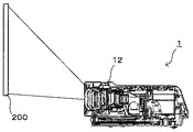
図1は、本実施形態に係るプロジェクタ1を示す斜視図である。図2は右側面図である。図1及び図2に示すように、プロジェクタ1の上面には、ユーザがプロジェクタ1を操作するための操作ボタン等の操作部11が設けられている。また、スクリーン200に映し出されている投射画面を拡大したり、縮小したりするズームレバー12が設けられている。プロジェクタ1の正面には、装置電源のオン/オフを行う電源スイッチ13、パソコンやビデオカメラ等の外部機器と接続するための外部入力端子14、投射画像の光を出射する投射レンズ15、装置環境の照度を検出するセンサ16などが設けられている。プロジェクタ1における外装カバーの右側面には、冷却用の空気を取り入れる吸気口17が設けられている。この吸気口17から外気を吸気する。吸引された外気は、熱源の光源や駆動基板へ移動しながら光源や駆動基板を冷却する。その後、排気ファン(不図示)により排気口(不図示)から排気される。
Hereinafter, an embodiment of a
FIG. 1 is a perspective view showing a
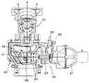
図3(a)は外装カバーを外したプロジェクタ1の内部構成と配置を示す斜視図、図3(b)は図3(a)の太線枠で囲まれた部分の斜視図である。図4は図3の断面線の横断面図であり、図5は図3の断面線の縦断面図である。図6はリレーレンズ周辺の拡大斜視図である。
図3〜図5に示すように、プロジェクタ1は、ハロゲンランプ、メタルハライドランプ、高圧水銀ランプなどの光源21を備えた光源部20と、光源21からの光を用いて画像を生成する画像生成部30と、投射画像を出射する投射光学部40とを有している。光源部20は、光源21、カラーホイール22、ライトトンネル23、2枚のリレーレンズ24(図6参照)を有している。そして、光源21からの光は、図4の矢印で示すように、回転するカラーホイール22を通ることにより時分割でR、G、Bの光に分離される。このカラーホイール22は、円盤形状のものであり、モータ25のモータ軸に固定され、回転方向にR(レッド)、G(グリーン)、B(ブルー)などのフィルタが設けられている。カラーホイール22により分離された光は、ライトトンネル23へ入射する。ライトトンネル23は、四角筒形状であり、その内周面が鏡面となっている。ライトトンネル23に入射した光は、ライトトンネル23の内周の鏡面で複数回反射しながら、均一な面光源にされて2枚のリレーレンズ24へ向けて出射する。図4の矢印で示すように、2枚のリレーレンズ24を透過し、次段の画像生成部30の平面ミラー31、凹面ミラー32により反射され、DMD33の画像生成面上に集光して結像される。
FIG. 3A is a perspective view showing the internal configuration and arrangement of the
As shown in FIGS. 3 to 5, the
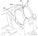
ここで、DMD33の画像生成面には、可動式の複数のマイクロミラーが格子状に配列されている。各マイクロミラーは、鏡面をねじれ軸周りに所定角度傾斜させることができ、「ON」と「OFF」の2つの状態を持たせることができる。マイクロミラーが「ON」のときは、光源部20の光源21からの光を投射光学部40の投射レンズに向けて反射する。「OFF」のときは、照明ブラケットなどの側面に保持されたOFF光板(不図示)に向けて光源21からの光を反射する。従って、各ミラーを個別に駆動することにより、画像データの画素ごとに光の投射を制御することができ、画像を生成することができる。なお、OFF光板(不図示)に向けて反射された光は、熱となって吸収され外側の空気の流れで冷却される。また、2枚のリレーレンズ24は、図6に示すように、板バネ状のレンズ押さえ部材26により両端がレンズブラケット27の突き当て面27aに押し付けられることにより、位置決め保持されている。
Here, a plurality of movable micromirrors are arranged in a grid pattern on the image generation surface of the
図1に示すプロジェクタ1は、パソコンやビデオカメラ等から入力される映像データを基に映像を生成し、その映像を図2の投射面としてのスクリーン200等に投射表示する。プロジェクタ1として広く知られた液晶プロジェクタは、近来、液晶パネルの高解像化、光源ランプの高効率化に伴う明るさの改善、低価格化などが進んでいる。また、画像表示素子であるDMDを利用した小型で、軽量なプロジェクタ1が普及し、オフィスや学校のみならず家庭においても広く利用されるようになってきている。光源21からの光が、光源部20内で、照射された白色光をカラーホイール22によってRGBに分光されて、画像生成部30のDMD33へ導かれ、変調信号に応じて画像形成するDMD33とその画像を投射光学部40で拡大投射する。
A
図7は、投射光学部40の断面図である。
図7に示すように、投射光学部40は、第1投射レンズ群44aと、第2投射レンズ群44bとを備えている。第1投射レンズ群44aは、第1レンズホルダ41に保持されており、第2投射レンズ群44bは、第2レンズホルダ42に保持されている。
FIG. 7 is a cross-sectional view of the projection
As shown in FIG. 7, the projection
先の図12を用いて説明したように、第1レンズホルダ41には、画像生成に用いられない所謂不要光が照射され、この不要光の赤外成分により加熱され、第1レンズホルダ41が温度上昇してしまう。上記第1レンズホルダ41は、樹脂などの熱膨張しやすい材料で形成されており、上記不要光の赤外成分による加熱により熱膨張し、保持している第1投射レンズ群44aの各投射レンズの位置が投射方向に変動し焦点距離が変動してしまう。また、第1レンズホルダ41の熱が、第1レンズホルダ41が保持する第1投射レンズ群の各投射レンズに伝達され、第1投射レンズ群の各投射レンズが温度上昇し、レンズが熱膨張する。レンズが熱膨張することで、レンズの曲率が変動し、スクリーン上の画像変動となって解像感を悪化させるおそれもある。そこで、本実施形態においては、第1レンズホルダ41の熱を放熱して、第1レンズホルダ41の温度上昇を抑制する放熱手段たる放熱機構50を備えている。
As described above with reference to FIG. 12, the
放熱機構50は、ヒートシンク51と、ヒートシンク51と第1レンズホルダとを熱的の連結する連結部材52とを有している。
The
図8は、投射光学部40の周辺を示す概略構成図である。図8(a)は、連結部材52側から見た図であり、図8(b)は、図8(a)の下方から見た図である。
連結部材52は、例えば、銅などの熱導電性のよい金属材料で構成されている。連結部材52は、第1レンズホルダ41の外周面に固定される第1レンズホルダ41の外周面の曲率に沿った形状の曲面部52aを有している。また、ヒートシンク51の側面に固定される板状部52b、曲面部52aと板状部52bとを連結する板状部52bから垂直に折れ曲がった連結部52cを有している。第1レンズホルダ41の曲面部52aが、第1レンズホルダ41に導熱性の高い接着剤により固定されている。一方、第1レンズホルダ41の板状部52bは、ヒートシンク51にネジ53により固定されている。
FIG. 8 is a schematic configuration diagram showing the periphery of the projection
The connecting
ヒートシンク51は、DMD33が実装されたDMD基板33aの裏面(DMDが実装された面と反対側の面)にネジ33bにより固定されている。ヒートシンク51には、DMD33の裏面(画像生成面と反対側の面)に接触させるための突起部51aが形成されている。DMD基板33aにヒートシンク51が固定されると、この突起部51aの先端面が、DMD33の裏面に接触する。これにより、DMD33の熱が、ヒートシンク51から放熱され、DMD33の温度上昇を抑制することができる。突起部51aの先端面とDMD33の裏面との間に弾性変形可能な伝熱シートを設け、突起部51aの先端面とDMD33の裏面との密着性を高めて、熱伝導性を高めてもよい。
The
本実施形態においては、第1レンズホルダ41の熱が、連結部材52に伝導し、連結部材52から第1レンズホルダ41の熱が放熱される。さらには、連結部材52からヒートシンク51に第1レンズホルダ41の熱が伝導し、ヒートシンクから第1レンズホルダ41の熱が放熱される。これにより、第1レンズホルダ41や第1レンズホルダが保持するレンズの温度上昇を抑制することができる。これにより、第1レンズホルダ41の熱膨張や第1レンズホルダが保持するレンズの熱膨張を抑制することができ、スクリーン上の画像の劣化を抑制することができる。
In the present embodiment, the heat of the
また、上述では、連結部材52を、放熱性の高い金属材料で構成しているが、例えば、熱伝導性の高い樹脂で形成してもよい。この場合は、第1レンズホルダの熱は、連結部材52を介して、ヒートシンク51に伝導され、主にヒートシンク51により放熱することになる。
In the above description, the connecting
また、第1レンズホルダ41を、焼結金属やセラミックなどの熱伝導性の高い部材で構成してもよい。このように、第1レンズホルダ41を焼結金属やセラミックなどの熱伝導性の高い部材で構成することにより、第1レンズホルダ41の熱を良好に連結部材52に伝導することができる。これにより、第1レンズホルダ41が保持するレンズの温度上昇を抑制することができ、レンズの熱膨張を抑制することができ、スクリーン上の画像の劣化を抑制することができる。
Moreover, you may comprise the
また、本実施形態においては、ヒートシンク51は、第1レンズホルダ41とDMD33の熱を放熱する。これにより、第1レンズホルダ41の熱を放熱する手段と、DMD33の熱を放熱する手段をそれぞれ設ける場合に比べて、部品点数を削減することができ、装置のコストアップを抑えることができる。
In the present embodiment, the
図9は、変形例1のプロジェクタの投射光学部40の周辺を示す概略構成図である。
図9に示すように、この変形例のプロジェクタは、冷却ファン61を設けて、ヒートシンク51を空冷するようにしたものである。ヒートシンク51を冷却ファン61により空冷することにより、DMD33および連結部材52から第1レンズホルダ41の熱を、効率よくヒートシンク51から放熱することができる。
FIG. 9 is a schematic configuration diagram illustrating the periphery of the projection
As shown in FIG. 9, the projector of this modification is provided with a cooling
また、ヒートシンク51は、DMD33の熱も伝導される関係で、ヒートシンク51が、第1レンズホルダ41の温度よりも高くなるおそれがある。その場合、ヒートシンク51の熱が、連結部材52を介して、第1レンズホルダ41に伝達されて、第1レンズホルダ41が、温度上昇するおそれがある。しかし、冷却ファンによりヒートシンク51を冷却することで、ヒートシンク51の温度が、第1レンズホルダ41の温度より高くなるのを抑制することができる。
Further, the
また、図9においては、冷却ファン61をヒートシンク51に対向して設けているが、冷却ファン61をヒートシンクと対向しない位置に設けて、ダクトを介して、冷却ファンが吸気した空気を、ヒートシンク51に送風してもよい。
In FIG. 9, the cooling
図10は、変形例2のプロジェクタの投射光学部40の周辺を示す概略構成図である。
図10に示すように、変形例2のプロジェクタは、連結部材52の第1レンズホルダ41との固定箇所に第1温度センサ62が設けられている。また、連結部材52のヒートシンク51との固定箇所に第2温度センサ63が設けられている。これら温度センサ62,63は、制御部64に接続されている。制御部64は、これら温度センサ62,63の検知結果に基づいて、冷却ファン61を制御する。
FIG. 10 is a schematic configuration diagram illustrating the periphery of the projection
As shown in FIG. 10, in the projector according to the second modification, the
図11は、冷却ファン61の制御フロー図である。
図11に示すように、制御部64は、第1温度センサ62の温度−第2温度センサ63の温度が、閾値未満か否かチェックする(S1)。閾値以上のとき(S1のNo)は、ヒートシンク51の温度が、第1レンズホルダ41の温度よりも十分低い。従って、この場合は、第1レンズホルダ41の熱が、連結部材52を介して、効率よくヒートシンク51の伝導される。よって、制御部64は、初期の回転数である第2回転数で、冷却ファン61が回転するよう冷却ファン61を制御する(S3)。
FIG. 11 is a control flow diagram of the cooling
As shown in FIG. 11, the control unit 64 checks whether or not the temperature of the
一方、第1温度センサ62の温度−第2温度センサ63の温度が、閾値未満のとき(S1のYES)は、ヒートシンク51の温度が高く、第1レンズホルダ41の熱が、ヒートシンク51に伝導しにくくなっている。従って、この場合、制御部64は、第2回転数よりも回転数が多い第1の回転数で冷却ファン61が回転するように制御する(S2)。
On the other hand, when the temperature of the
このようにして、冷却ファン61を制御することにより、ヒートシンク51の温度が、第1レンズホルダ41よりも高くなるのを確実に防止することができる。また、ヒートシンク51の温度が、第1レンズホルダ41よりも十分低いとき、冷却ファン61の回転数が落とされるので、冷却ファン61の風切り音による騒音を抑制することができる。また、冷却ファンに印加する電力を抑えることができ、消費電力の増大を抑えることができる。
In this way, by controlling the cooling
また、図10では、第1温度センサ62を、連結部材52の第1レンズホルダ41との固定箇所に設けているが、第1レンズホルダ41に設けてもよい。また、第2温度センサ63は、ヒートシンク51に設けてもよい。
In FIG. 10, the
また、図11に示した制御フローでは、閾値がひとつであったが、閾値を複数設けて、冷却ファン61の回転数を細かく制御してもよい。また、第1温度センサ62の温度から第2温度センサの温度を減算した値が、十分大きな値のときは、冷却ファン61を停止するように制御してもよい。
In the control flow shown in FIG. 11, the threshold value is one, but a plurality of threshold values may be provided to finely control the rotation speed of the cooling
また、上述では、第1レンズホルダ41の熱を、連結部材52を介して、ヒートシンク51に伝導しているが、第1レンズホルダ41に放熱手段としてのヒートシンク51を設けて、第1レンズホルダ41の熱を直接、ヒートシンク51に伝導させてもよい。
In the above description, the heat of the
以上に説明したものは一例であり、本発明は、以下の態様毎に特有の効果を奏する。
(態様1)
DMD33などの画像生成素子で生成された画像を、第1レンズホルダ41などの投射レンズ保持部によって保持された投射レンズ(第1投射レンズ群44aを構成する投射レンズ)を介してスクリーン200などの投射面に向けて投射する投射光学部40などの投射光学装置において、投射レンズ保持部に投射レンズ保持部の熱を放熱するヒートシンク51などの放熱手段を設けた。
かかる構成を備えることで、実施形態で説明したように、ヒートシンク51などの放熱手段により第1レンズホルダ41などの投射レンズ保持部の熱を放熱することができる。これにより、投射レンズ保持部の温度上昇を抑制することができ、投射レンズ保持部の熱膨張が抑制される。その結果、投射レンズ保持部が保持している投射レンズの位置が投射方向に変動するのを抑制することができる。これにより、焦点距離が変動するのを抑制することができる。
What has been described above is an example, and the present invention has a specific effect for each of the following aspects.
(Aspect 1)
An image generated by an image generation element such as the
With this configuration, as described in the embodiment, the heat of the projection lens holding unit such as the
(態様2)
(態様1)において、第1レンズホルダ41などのレンズ保持部と、ヒートシンク51などの放熱手段とは、金属製の部材で連結されている。
かかる構成を備えることで、実施形態で説明したように、第1レンズホルダ41などのレンズ保持部の熱を、ヒートシンク51などの放熱手段へ効率よく伝導することができ、レンズ保持部の温度上昇を良好に抑制することができる。
(Aspect 2)
In (Aspect 1), the lens holding portion such as the
With this configuration, as described in the embodiment, the heat of the lens holding unit such as the
(態様3)
また、(態様1)または(態様2)において、ヒートシンク51などの放熱手段は、DMD33などの画像生成素子の熱も放熱する。
かかる構成を備えることで、実施形態で説明したように、第1レンズホルダ41などのレンズ保持部を放熱する放熱手段と、DMD33などの画像生成部の熱を放熱する放熱手段とをそれぞれ設ける場合に比べて、部品点数を削減できる。これにより、装置のコストアップを抑制することができる。
(Aspect 3)
In (Aspect 1) or (Aspect 2), the heat radiating means such as the
By providing such a configuration, as described in the embodiment, a heat dissipating unit that dissipates heat from the lens holding unit such as the
(態様4)
また、(態様1)乃至(態様3)において、ヒートシンク51などの放熱手段を冷却する冷却ファン61などの冷却手段を備えた。
かかる構成を備えることで、変形例1で説明したように、ヒートシンク51などの放熱手段の温度上昇を抑えることができ、効率よく、第1レンズホルダ41などのレンズ保持部の温度上昇を抑制することができる。
(Aspect 4)
Further, in (Aspect 1) to (Aspect 3), a cooling means such as a cooling
With this configuration, as described in the first modification, it is possible to suppress the temperature rise of the heat radiating means such as the
(態様5)
また、(態様4)において、第1レンズホルダ41などのレンズ保持部の温度を検知する第1温度センサ62などの第1温度検知手段と、ヒートシンク51などの放熱手段の温度を検知する第2温度センサ63などの第2温度検知手段と、第1温度検知手段の検知結果と第2温度検知手段の検知結果とに基づいて、冷却ファン61などの冷却手段を制御する制御部64などの制御手段とを備えた。
これにより、変形例2で説明したように、第1レンズホルダ41などのレンズ保持部の熱を効率よくヒートシンク51により放熱することができ、レンズ保持部の温度上昇を良好に抑制することができる。
(Aspect 5)
In (Aspect 4), the first temperature detecting means such as the
Accordingly, as described in the second modification, the heat of the lens holding portion such as the
(態様6)
光源21と、光源21からの光を用いて画像を生成する画像生成素子30と、複数の光学素子を備え、画像を投影面に向けて投射する投射光学部40とを備えた画像投影装置のプロジェクタ1において、上記投射光学部として、(態様1)〜(態様5)のいずれかの投射光学装置を用いたことを特徴とする。
これにより、上記実施形態について説明したように、画像を生成する光以外の光による投影画像の画質悪化を抑制できる。
(Aspect 6)
An image projection apparatus including a
Thereby, as described in the above embodiment, it is possible to suppress deterioration in the image quality of the projected image due to light other than the light that generates the image.
1 プロジェクタ
11 操作部
15 投射レンズ
21 光源
22 カラーホイール
23 ライトトンネル
24 リレーレンズ
30 画像生成部
31 平面ミラー
32 凹面ミラー
33 DMD
33a 基板
33b ネジ
40 投射光学部
41 第1レンズホルダ
42 第2レンズホルダ
44a 第1投射レンズ群
44b 第2投射レンズ群
50 放熱機構
51 ヒートシンク
52 連結部材
52a 曲面部
52b 板状部
52c 連結部
61 冷却ファン
62 第1温度センサ
63 第2温度センサ
64 制御部
DESCRIPTION OF
Claims (6)
前記投射レンズ保持部に前記投射レンズ保持部の熱を放熱する放熱手段を設けたことを特徴とする投射光学装置。 In the projection optical device that projects the image generated by the image generation element toward the projection surface via the projection lens held by the projection lens holding unit,
A projection optical apparatus, wherein the projection lens holding part is provided with a heat radiating means for radiating heat of the projection lens holding part.
前記レンズ保持部と、前記放熱手段とは、金属製の部材で連結されていることを特徴とする投射光学装置。 The projection optical apparatus according to claim 1,
The lens holding unit and the heat radiating means are connected by a metal member.
前記放熱手段は、前記画像生成素子の熱も放熱することを特徴とする投射光学装置。 In the projection optical apparatus according to claim 1 or 2,
The projection optical apparatus, wherein the heat radiating means also radiates heat of the image generating element.
前記放熱手段を冷却する冷却手段を備えたことを特徴とする投射光学装置。 In the projection optical apparatus according to any one of claims 1 to 3,
A projection optical apparatus comprising cooling means for cooling the heat dissipation means.
前記レンズ保持部の温度を検知する第1温度検知手段と、
前記放熱手段の温度を検知する第2温度検知手段と、
前記第1温度検知手段の検知結果と第2温度検知手段の検知結果とに基づいて、前記冷却手段を制御する制御手段とを備えたことを特徴とする投射光学装置。 The projection optical apparatus according to claim 4,
First temperature detecting means for detecting the temperature of the lens holding portion;
Second temperature detection means for detecting the temperature of the heat dissipation means;
A projection optical apparatus comprising: a control unit that controls the cooling unit based on a detection result of the first temperature detection unit and a detection result of the second temperature detection unit.
前記投射光学部として、請求項1乃至5いずれかに記載の投射光学装置を用いたことを特徴とする画像投射装置。 In an image projection apparatus comprising: a light source; an image generation element that generates an image using light from the light source; and a projection optical unit that includes a plurality of optical elements and projects the image toward a projection surface.
An image projection apparatus using the projection optical apparatus according to claim 1 as the projection optical unit.
Priority Applications (1)
| Application Number | Priority Date | Filing Date | Title |
|---|---|---|---|
| JP2013147860A JP2015022020A (en) | 2013-07-16 | 2013-07-16 | Projection optical device and image projection device |
Applications Claiming Priority (1)
| Application Number | Priority Date | Filing Date | Title |
|---|---|---|---|
| JP2013147860A JP2015022020A (en) | 2013-07-16 | 2013-07-16 | Projection optical device and image projection device |
Publications (2)
| Publication Number | Publication Date |
|---|---|
| JP2015022020A true JP2015022020A (en) | 2015-02-02 |
| JP2015022020A5 JP2015022020A5 (en) | 2017-01-12 |
Family
ID=52486553
Family Applications (1)
| Application Number | Title | Priority Date | Filing Date |
|---|---|---|---|
| JP2013147860A Pending JP2015022020A (en) | 2013-07-16 | 2013-07-16 | Projection optical device and image projection device |
Country Status (1)
| Country | Link |
|---|---|
| JP (1) | JP2015022020A (en) |
Cited By (2)
| Publication number | Priority date | Publication date | Assignee | Title |
|---|---|---|---|---|
| JP2017021291A (en) * | 2015-07-14 | 2017-01-26 | 株式会社リコー | Image projection apparatus |
| US9829671B2 (en) | 2015-07-30 | 2017-11-28 | Ricoh Company, Ltd. | Projection lens unit, optical engine, and image projecting apparatus |
Citations (3)
| Publication number | Priority date | Publication date | Assignee | Title |
|---|---|---|---|---|
| JP2006139022A (en) * | 2004-11-11 | 2006-06-01 | Seiko Epson Corp | Projector |
| JP2006301368A (en) * | 2005-04-21 | 2006-11-02 | Casio Comput Co Ltd | Data projector |
| JP2010060884A (en) * | 2008-09-04 | 2010-03-18 | Casio Comput Co Ltd | Projection device, projection method and program |
-
2013
- 2013-07-16 JP JP2013147860A patent/JP2015022020A/en active Pending
Patent Citations (3)
| Publication number | Priority date | Publication date | Assignee | Title |
|---|---|---|---|---|
| JP2006139022A (en) * | 2004-11-11 | 2006-06-01 | Seiko Epson Corp | Projector |
| JP2006301368A (en) * | 2005-04-21 | 2006-11-02 | Casio Comput Co Ltd | Data projector |
| JP2010060884A (en) * | 2008-09-04 | 2010-03-18 | Casio Comput Co Ltd | Projection device, projection method and program |
Cited By (2)
| Publication number | Priority date | Publication date | Assignee | Title |
|---|---|---|---|---|
| JP2017021291A (en) * | 2015-07-14 | 2017-01-26 | 株式会社リコー | Image projection apparatus |
| US9829671B2 (en) | 2015-07-30 | 2017-11-28 | Ricoh Company, Ltd. | Projection lens unit, optical engine, and image projecting apparatus |
Similar Documents
| Publication | Publication Date | Title |
|---|---|---|
| JP5083590B2 (en) | Projection-side optical system and projector | |
| KR100643977B1 (en) | Optical device and projector having the optical device | |
| JP4228319B2 (en) | Optical system unit and projector | |
| CN107490928B (en) | Fluorescent light emitting device, light source device, and image projection device | |
| JP7049574B2 (en) | Cooling device, light source device and projection device | |
| US9423677B2 (en) | Cooling structure, image projection apparatus, electronic device, and cooling device | |
| JP2014153578A (en) | Head-up display | |
| JP5700494B2 (en) | Projection device | |
| JP2018156874A (en) | Light source device and projection device | |
| JP6551752B2 (en) | Light source device and projection device | |
| JP2014146742A (en) | Head-up display | |
| JP2006208454A (en) | Projector | |
| JP5136833B2 (en) | projector | |
| JP2016051121A (en) | Projection optical device and image projection device | |
| JP2000269674A (en) | Liquid crystal projector | |
| JP4986019B2 (en) | Optical system unit and projector | |
| JP2015022020A (en) | Projection optical device and image projection device | |
| JP2012203350A (en) | Cooling apparatus and projector | |
| JP4175327B2 (en) | Projector device | |
| JP2017223844A (en) | Image projection device | |
| US9395607B2 (en) | Image projection apparatus including a shield | |
| JP2015011272A (en) | Projection optical device and image projection device | |
| JP2006259290A (en) | Light source device and projector with it | |
| WO2015111364A1 (en) | Image projection device, control method, and program | |
| JP2005121712A (en) | Projector |
Legal Events
| Date | Code | Title | Description |
|---|---|---|---|
| A621 | Written request for application examination |
Free format text: JAPANESE INTERMEDIATE CODE: A621 Effective date: 20160707 |
|
| A521 | Request for written amendment filed |
Free format text: JAPANESE INTERMEDIATE CODE: A523 Effective date: 20161129 |
|
| A977 | Report on retrieval |
Free format text: JAPANESE INTERMEDIATE CODE: A971007 Effective date: 20170424 |
|
| A131 | Notification of reasons for refusal |
Free format text: JAPANESE INTERMEDIATE CODE: A131 Effective date: 20170526 |
|
| A02 | Decision of refusal |
Free format text: JAPANESE INTERMEDIATE CODE: A02 Effective date: 20171208 |