WO2016117308A1 - エジェクタ - Google Patents
エジェクタ Download PDFInfo
- Publication number
- WO2016117308A1 WO2016117308A1 PCT/JP2016/000172 JP2016000172W WO2016117308A1 WO 2016117308 A1 WO2016117308 A1 WO 2016117308A1 JP 2016000172 W JP2016000172 W JP 2016000172W WO 2016117308 A1 WO2016117308 A1 WO 2016117308A1
- Authority
- WO
- WIPO (PCT)
- Prior art keywords
- refrigerant
- passage
- space
- forming member
- ejector
- Prior art date
- Legal status (The legal status is an assumption and is not a legal conclusion. Google has not performed a legal analysis and makes no representation as to the accuracy of the status listed.)
- Ceased
Links
Images




Classifications
-
- F—MECHANICAL ENGINEERING; LIGHTING; HEATING; WEAPONS; BLASTING
- F04—POSITIVE - DISPLACEMENT MACHINES FOR LIQUIDS; PUMPS FOR LIQUIDS OR ELASTIC FLUIDS
- F04F—PUMPING OF FLUID BY DIRECT CONTACT OF ANOTHER FLUID OR BY USING INERTIA OF FLUID TO BE PUMPED; SIPHONS
- F04F5/00—Jet pumps, i.e. devices in which flow is induced by pressure drop caused by velocity of another fluid flow
- F04F5/02—Jet pumps, i.e. devices in which flow is induced by pressure drop caused by velocity of another fluid flow the inducing fluid being liquid
- F04F5/04—Jet pumps, i.e. devices in which flow is induced by pressure drop caused by velocity of another fluid flow the inducing fluid being liquid displacing elastic fluids
-
- F—MECHANICAL ENGINEERING; LIGHTING; HEATING; WEAPONS; BLASTING
- F04—POSITIVE - DISPLACEMENT MACHINES FOR LIQUIDS; PUMPS FOR LIQUIDS OR ELASTIC FLUIDS
- F04F—PUMPING OF FLUID BY DIRECT CONTACT OF ANOTHER FLUID OR BY USING INERTIA OF FLUID TO BE PUMPED; SIPHONS
- F04F5/00—Jet pumps, i.e. devices in which flow is induced by pressure drop caused by velocity of another fluid flow
- F04F5/44—Component parts, details, or accessories not provided for in, or of interest apart from, groups F04F5/02 - F04F5/42
-
- F—MECHANICAL ENGINEERING; LIGHTING; HEATING; WEAPONS; BLASTING
- F04—POSITIVE - DISPLACEMENT MACHINES FOR LIQUIDS; PUMPS FOR LIQUIDS OR ELASTIC FLUIDS
- F04F—PUMPING OF FLUID BY DIRECT CONTACT OF ANOTHER FLUID OR BY USING INERTIA OF FLUID TO BE PUMPED; SIPHONS
- F04F5/00—Jet pumps, i.e. devices in which flow is induced by pressure drop caused by velocity of another fluid flow
- F04F5/44—Component parts, details, or accessories not provided for in, or of interest apart from, groups F04F5/02 - F04F5/42
- F04F5/46—Arrangements of nozzles
-
- F—MECHANICAL ENGINEERING; LIGHTING; HEATING; WEAPONS; BLASTING
- F25—REFRIGERATION OR COOLING; COMBINED HEATING AND REFRIGERATION SYSTEMS; HEAT PUMP SYSTEMS; MANUFACTURE OR STORAGE OF ICE; LIQUEFACTION SOLIDIFICATION OF GASES
- F25B—REFRIGERATION MACHINES, PLANTS OR SYSTEMS; COMBINED HEATING AND REFRIGERATION SYSTEMS; HEAT PUMP SYSTEMS
- F25B1/00—Compression machines, plants or systems with non-reversible cycle
Definitions
- the present disclosure relates to an ejector that sucks fluid by a suction action of a jet fluid ejected at a high speed.
- Patent Document 1 is applied to a vapor compression refrigeration cycle apparatus, and sucks refrigerant from a refrigerant suction port by a suction action of a jet refrigerant injected at a high speed, and mixes the jet refrigerant and the suction refrigerant.
- An ejector for boosting pressure is disclosed.
- a substantially conical passage forming member is disposed inside the body, and a refrigerant passage having an annular cross section is formed in a gap between the body and the conical side surface of the passage forming member.
- this refrigerant passage the portion on the most upstream side of the refrigerant flow is used as a nozzle passage for depressurizing and injecting the high-pressure refrigerant, and the portion on the downstream side of the refrigerant flow in the nozzle passage is mixed with the injected refrigerant and the suction refrigerant.
- This is used as a diffuser passage for increasing the pressure of the mixed refrigerant.
- the ejector of Patent Document 1 includes a drive device that displaces the passage forming member, and the passage forming member is displaced according to the load fluctuation of the refrigeration cycle apparatus.
- the ejector is appropriately operated by adjusting the passage sectional area of the refrigerant passage in accordance with the flow rate of the refrigerant circulating in the cycle.
- Patent Document 1 employs a passage forming member formed of a highly durable metal in order to appropriately change the passage cross-sectional area of the refrigerant passage. Therefore, the weight of the passage forming member becomes heavy, and the resonance frequency of the vibration system including the passage forming member tends to be a relatively low frequency.
- the inventors of the present application studied lightening of the passage forming member by forming the passage forming member with resin.
- the passage forming member made of resin is more likely to be damaged or deformed than that made of metal. Further, among the passage forming members, if the conical side surface forming the refrigerant passage or a portion that receives a load when it is displaced is damaged or deformed, the passage forming member according to the load fluctuation of the refrigeration cycle apparatus. Even if it is displaced, the cross-sectional area of the refrigerant passage cannot be changed appropriately.
- an object of the present disclosure is to appropriately adjust the passage cross-sectional area of the refrigerant passage while reducing the weight of the passage formation member in the ejector including the passage formation member.
- the ejector according to the first aspect of the present disclosure may be applied to a vapor compression refrigeration cycle apparatus.
- the ejector includes a decompression space that decompresses the refrigerant that has flowed from the refrigerant inlet, a suction passage that communicates with the downstream side of the refrigerant flow in the decompression space and distributes the refrigerant sucked from the outside, and an injection that is ejected from the decompression space
- a passage forming member formed in a conical shape whose cross-sectional area increases with distance from the side, and a drive device that displaces the passage forming member.
- the refrigerant passage formed between the inner peripheral surface of the part of the body that forms the decompression space and the outer peripheral surface of the passage forming member is a nozzle that functions as a nozzle that decompresses and injects the refrigerant flowing from the refrigerant inlet.
- the refrigerant passage formed between the inner peripheral surface of the portion of the body that forms the pressure increasing space and the outer peripheral surface of the passage forming member serves as a pressure increasing unit that increases the pressure by mixing the injected refrigerant and the suction refrigerant.
- the passage forming member has a metal portion formed of metal and a resin portion formed of resin, and the metal portion is an outer peripheral surface of a portion forming the nozzle passage, and at least the nozzle The outer peripheral surface including the site
- the passage forming member since the passage forming member has the resin portion, the weight can be reduced as compared with the case where all the portions are formed of metal.
- the outer peripheral surface including the part that forms the minimum passage area portion of the nozzle passage is formed of the metal portion in the outer peripheral surface of the passage forming member, damage and deformation of the outer peripheral surface can be suppressed. Therefore, it is possible to suppress the passage cross-sectional area of the minimum passage area portion of the nozzle passage from being changed due to damage or deformation of the passage forming member.
- the passage cross-sectional area of the refrigerant passage formed inside can be appropriately adjusted while reducing the weight of the passage forming member.
- the ejector can be appropriately operated according to the load fluctuation of the refrigeration cycle apparatus.
- An ejector includes: a decompression space that decompresses the refrigerant that has flowed from the refrigerant inlet; a suction passage that communicates with the downstream side of the refrigerant flow in the decompression space and that circulates the refrigerant sucked from outside; A body in which a pressure increasing space for mixing the refrigerant injected from the working space and the suction refrigerant sucked from the suction passage is formed, and at least a part thereof is disposed in the pressure reducing space and the pressure increasing space.
- a passage forming member formed in a conical shape whose cross-sectional area expands with distance from the decompression space side, and an elastic member that applies a load to the passage forming member are provided.
- the refrigerant passage formed between the inner peripheral surface of the part of the body that forms the decompression space and the outer peripheral surface of the passage forming member is a nozzle that functions as a nozzle that decompresses and injects the refrigerant flowing from the refrigerant inlet.
- the refrigerant passage formed between the inner peripheral surface of the portion of the body that forms the pressure increasing space and the outer peripheral surface of the passage forming member serves as a pressure increasing unit that increases the pressure by mixing the injected refrigerant and the suction refrigerant.
- a functioning diffuser passage wherein the passage forming member has a metal portion formed of metal and a resin portion formed of resin, and the metal portion is made of an elastic member among the passage forming members.
- the part which touches is formed. According to this, since the channel
- path formation members is formed of the metal part, the damage and deformation
- the passage cross-sectional area of the refrigerant passage formed inside can be appropriately adjusted while reducing the weight of the passage forming member.
- the ejector 13 of the present embodiment is applied to a vapor compression refrigeration cycle apparatus including an ejector as a refrigerant decompression unit, that is, an ejector refrigeration cycle 10, as shown in the overall configuration diagram of FIG. Furthermore, this ejector type refrigeration cycle 10 is applied to a vehicle air conditioner, and fulfills a function of cooling the blown air blown into the vehicle interior, which is the air-conditioning target space. Therefore, the cooling target fluid of the ejector refrigeration cycle 10 of the present embodiment is blown air.
- the ejector refrigeration cycle 10 of the present embodiment employs an HFC-based refrigerant (specifically, R134a) as the refrigerant, and constitutes a subcritical refrigeration cycle in which the high-pressure side refrigerant pressure does not exceed the refrigerant critical pressure. is doing.
- an HFO refrigerant specifically, R1234yf
- refrigeration oil for lubricating the compressor 11 is mixed in the refrigerant, and a part of the refrigeration oil circulates in the cycle together with the refrigerant.
- the compressor 11 in the ejector refrigeration cycle 10 sucks the refrigerant and discharges it until it becomes a high-pressure refrigerant.
- the compressor 11 of the present embodiment is an electric compressor configured by housing a fixed capacity type compression mechanism and an electric motor that drives the compression mechanism in one housing.
- various compression mechanisms such as a scroll-type compression mechanism and a vane-type compression mechanism can be adopted. Further, the operation (rotation speed) of the electric motor is controlled by a control signal output from a control device to be described later, and either an AC motor or a DC motor may be adopted.
- the refrigerant inlet side of the condenser 12 a of the radiator 12 is connected to the discharge port of the compressor 11.
- the radiator 12 is a heat exchanger for heat radiation that radiates and cools the high-pressure refrigerant by exchanging heat between the high-pressure refrigerant discharged from the compressor 11 and outside air (outside air) blown by the cooling fan 12d. .
- the heat radiator 12 exchanges heat between the high-pressure gas-phase refrigerant discharged from the compressor 11 and the outside air blown from the cooling fan 12d, and dissipates the high-pressure gas-phase refrigerant to condense and condense the part 12a.
- the receiver 12b that separates the gas-liquid of the refrigerant that has flowed out of the condensing unit 12a and stores excess liquid-phase refrigerant, and the liquid-phase refrigerant that has flowed out of the receiver 12b and the outside air blown from the cooling fan 12d exchange heat.
- This is a so-called subcool condenser that includes a supercooling unit 12c that supercools the liquid refrigerant.
- the cooling fan 12d is an electric blower whose rotation speed (amount of blown air) is controlled by a control voltage output from the control device.
- a refrigerant inlet 31 a of the ejector 13 is connected to the refrigerant outlet side of the supercooling portion 12 c of the radiator 12.
- the ejector 13 functions as a refrigerant pressure reducing unit that depressurizes the supercooled high-pressure liquid-phase refrigerant that has flowed out of the radiator 12 and flows it to the downstream side, and is described later by the suction action of the refrigerant flow injected at a high speed. It also functions as a refrigerant circulation section (refrigerant transport section) that sucks (transports) and circulates the refrigerant flowing out of the evaporator 14 that circulates.
- refrigerant circulation section refrigerant transport section
- the ejector 13 of the present embodiment also functions as a gas-liquid separation unit that separates the gas-liquid of the decompressed refrigerant. That is, the ejector 13 of the present embodiment is configured as an ejector with a gas-liquid separation function (ejector module).
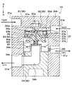
- FIG. 2 is a schematic cross-sectional view for explaining the function of each refrigerant passage of the ejector 13, and parts having the same functions as those in FIG. 2 are denoted by the same reference numerals.
- the ejector 13 of the present embodiment includes a body 30 configured by combining a plurality of constituent members.
- the body 30 has a housing body 31 that is formed of a prismatic or columnar metal or resin and forms the outer shell of the ejector 13. Further, a nozzle body 32, a middle body 33, and a lower body 34 are fixed inside the housing body 31.
- the housing body 31 includes a refrigerant inlet 31 a that allows the refrigerant flowing out of the radiator 12 to flow into the interior, a refrigerant suction port 31 b that sucks the refrigerant flowing out of the evaporator 14, and a gas-liquid separation space formed inside the body 30.
- the liquid-phase refrigerant outlet 31c that causes the liquid-phase refrigerant separated in 30f to flow out to the refrigerant inlet side of the evaporator 14 and the gas-phase refrigerant separated in the gas-liquid separation space 30f to the inlet side of the compressor 11
- a gas-phase refrigerant outlet 31d and the like are formed.
- an orifice 30i as a pressure reducing device that depressurizes the refrigerant flowing into the evaporator 14 is disposed in the liquid phase refrigerant passage connecting the gas-liquid separation space 30f and the liquid phase refrigerant outlet 31c. .
- the nozzle body 32 is formed of a substantially conical metal member that tapers in the refrigerant flow direction. Further, the nozzle body 32 is fixed to the inside of the housing body 31 by means such as press fitting so that the axial direction is the vertical direction (the vertical direction in FIG. 2). Between the upper side of the nozzle body 32 and the housing body 31, a swirling space 30a for swirling the refrigerant flowing from the refrigerant inlet 31a is formed.
- the swirling space 30a is formed in a rotating body shape, and the central axis shown by the one-dot chain line in FIG. 2 extends in the vertical direction.
- the rotating body shape is a three-dimensional shape formed when a plane figure is rotated around one straight line (central axis) on the same plane. More specifically, the swirl space 30a of the present embodiment is formed in a substantially cylindrical shape. Of course, you may form in the shape etc. which combined the cone or the truncated cone, and the cylinder.
- the refrigerant inflow passage 31e that connects the refrigerant inlet 31a and the swirl space 30a extends in the tangential direction of the inner wall surface of the swirl space 30a when viewed from the central axis direction of the swirl space 30a. Thereby, the refrigerant that has flowed into the swirl space 30a from the refrigerant inflow passage 31e flows along the inner wall surface of the swirl space 30a and swirls around the central axis of the swirl space 30a.
- the refrigerant pressure on the central axis side is lower than the refrigerant pressure on the outer peripheral side in the swirling space 30a. Therefore, in the present embodiment, during normal operation of the ejector refrigeration cycle 10, the refrigerant pressure on the central axis side in the swirling space 30a is set to the pressure that becomes the saturated liquid phase refrigerant, or the refrigerant boils under reduced pressure (causes cavitation). The pressure is reduced until the pressure is reached.
- Such adjustment of the refrigerant pressure on the central axis side in the swirling space 30a can be realized by adjusting the swirling flow velocity of the refrigerant swirling in the swirling space 30a.
- the swirl flow rate can be adjusted by adjusting the area ratio between the passage sectional area of the refrigerant inflow passage 31e and the vertical sectional area in the axial direction of the swirling space 30a, for example.
- the swirling flow velocity in the present embodiment means the flow velocity in the swirling direction of the refrigerant in the vicinity of the outermost peripheral portion of the swirling space 30a.
- a decompression space 30b is formed in which the refrigerant that has flowed out of the swirling space 30a is decompressed and flows downstream.
- the decompression space 30b is formed in a rotating body shape in which a cylindrical space and a frustoconical space that continuously spreads from the lower side of the cylindrical space and gradually expands in the refrigerant flow direction.
- the central axis of the working space 30b is arranged coaxially with the central axis of the swirling space 30a.
- a forming member 35 is disposed.
- the passage forming member 35 is formed in a substantially conical shape that gradually expands toward the downstream side of the refrigerant flow, and the central axis thereof is arranged coaxially with the central axis of the decompression space 30b. That is, the passage forming member 35 is formed in a conical shape whose cross-sectional area increases as it moves away from the decompression space 30b side. The detailed configuration of the passage forming member 35 will be described later.
- the tip 131 is formed as a refrigerant passage formed between the inner peripheral surface of the portion of the nozzle body 32 that forms the pressure reducing space 30 b and the upper outer peripheral surface of the passage forming member 35.
- the divergent part 132 is formed.
- the tapered portion 131 is a refrigerant passage that is formed on the upstream side of the refrigerant flow with respect to the minimum passage area portion 30m and that the passage cross-sectional area up to the minimum passage area portion 30m gradually decreases.
- the divergent portion 132 is a refrigerant passage that is formed on the downstream side of the refrigerant flow from the minimum passage area portion 30m, and the passage cross-sectional area gradually increases.
- the decompression space 30b and the passage forming member 35 are overlapped (overlapped) when viewed from the radial direction, so that the shape of the axial cross section of the refrigerant passage is annular (from circular to coaxial). Donut shape excluding a small-diameter circular shape arranged on the top). Furthermore, the passage cross-sectional area in the divergent portion 132 gradually increases toward the downstream side of the refrigerant flow.
- the refrigerant passage formed between the inner peripheral surface of the pressure reducing space 30b and the outer peripheral surface on the top side of the passage forming member 35 by such a passage shape is the nozzle passage 13a that functions as a Laval nozzle, and the refrigerant The pressure of the refrigerant is reduced and the flow rate of the refrigerant is increased so as to be supersonic.
- the middle body 33 is provided with a through-hole penetrating the front and back (up and down) at the center thereof. Further, the middle body 33 is formed of a metal disk-like member that houses a drive mechanism 37 that displaces the passage forming member 35 on the outer peripheral side of the through hole.
- the central axis of the through hole of the middle body 33 is arranged coaxially with the central axes of the swirl space 30a and the decompression space 30b.
- the middle body 33 is fixed inside the housing body 31 and below the nozzle body 32 by means such as press fitting.
- an inflow space 30c is formed between the upper surface of the middle body 33 and the inner wall surface of the housing body 31 opposite to the middle body 33 for retaining the refrigerant flowing in from the refrigerant suction port 31b.
- the inflow space 30c since the tapered tip portion on the lower side of the nozzle body 32 is positioned inside the through hole of the middle body 33, the inflow space 30c has a cross section when viewed from the central axis direction of the swirl space 30a and the decompression space 30b. It is formed in an annular shape.
- the lower side of the nozzle body 32 is inserted, that is, in the range where the middle body 33 and the nozzle body 32 overlap when viewed from the radial direction perpendicular to the axis, the taper tip of the nozzle body 32 is formed.
- the refrigerant passage cross-sectional area gradually decreases in the refrigerant flow direction so as to conform to the outer peripheral shape.
- a suction passage 30d is formed between the inner peripheral surface of the through hole and the outer peripheral surface on the lower side of the nozzle body 32 to connect the inflow space 30c and the refrigerant flow downstream side of the decompression space 30b. That is, in the present embodiment, the suction passage 13b through which the suction refrigerant flows from the outer peripheral side to the inner peripheral side of the central axis is formed by the inflow space 30c and the suction passage 30d.
- the cross section perpendicular to the central axis of the suction passage 13b is also formed in an annular cross section.
- a pressure increasing space 30e formed in a substantially truncated cone shape gradually spreading in the refrigerant flow direction is formed on the downstream side of the refrigerant flow in the suction passage 30d.
- the pressurizing space 30e is a space for mixing the refrigerant injected from the nozzle passage 13a and the suction refrigerant sucked from the suction passage 30d.
- the central axis of the pressurizing space 30e is arranged coaxially with the central axes of the swirling space 30a and the decompressing space 30b.
- the lower side of the passage forming member 35 is disposed inside the pressurizing space 30e. Further, the refrigerant passage formed between the inner peripheral surface of the portion forming the pressurizing space 30e of the middle body 33 and the outer peripheral surface on the lower side of the passage forming member 35 has a passage sectional area toward the downstream side of the refrigerant flow. It is formed into a shape that gradually expands. Thereby, in this refrigerant path, the velocity energy of the mixed refrigerant of the injection refrigerant and the suction refrigerant can be converted into pressure energy.
- a diffuser passage 13c that functions as a diffuser (a boosting unit) for mixing and boosting is configured.
- the cross section of the diffuser passage 13c perpendicular to the central axis is also formed in an annular shape.
- the drive mechanism 37 includes a circular thin plate-like diaphragm 37a that is a pressure responsive member. More specifically, as shown in FIG. 2, the diaphragm 37a is fixed by means such as welding so as to partition a cylindrical space formed on the outer peripheral side of the middle body 33 into two upper and lower spaces.
- the space on the upper side changes in pressure according to the temperature of the refrigerant on the outlet side of the evaporator 14 (specifically, the refrigerant that has flowed out of the evaporator 14).
- An enclosed space 37b in which a temperature sensitive medium is enclosed is configured.
- a temperature sensitive medium having the same composition as the refrigerant circulating in the ejector refrigeration cycle 10 is enclosed in the enclosed space 37b so as to have a predetermined density. Therefore, the temperature sensitive medium in the present embodiment is a medium mainly composed of R134a.
- the lower space of the two spaces partitioned by the diaphragm 37a constitutes an introduction space 37c for introducing the refrigerant on the outlet side of the evaporator 14 via a communication path (not shown). Accordingly, the temperature of the refrigerant on the outlet side of the evaporator 14 is transmitted to the temperature sensitive medium enclosed in the enclosed space 37b via the lid member 37d and the diaphragm 37a that partition the inflow space 30c and the enclosed space 37b.
- the diaphragm 37a is deformed according to a differential pressure between the internal pressure of the enclosed space 37b and the pressure of the evaporator 14 outlet side refrigerant that has flowed into the introduction space 37c.
- the diaphragm 37a is made of a tough material that is rich in elasticity and has good heat conduction. Accordingly, a thin metal plate such as stainless steel (SUS304) may be used as the diaphragm 37a, or a rubber made material such as EPDM (ethylene propylene diene copolymer rubber) containing a base fabric that is excellent in pressure resistance and sealability. May be.
- a columnar actuating rod 37e is joined to the center portion of the diaphragm 37a by means such as welding, and the outer peripheral side of the lowermost portion (bottom portion) of the passage forming member 35 is fixed to the lower end side of the actuating rod 37e.
- the diaphragm 37a and the passage forming member 35 are connected, and the passage forming member 35 is displaced in accordance with the displacement of the diaphragm 37a, and the passage sectional area in the minimum passage area portion 30m of the nozzle passage 13a is adjusted.
- the diaphragm 37a displaces the channel
- the diaphragm 37a displaces the passage forming member 35 in a direction (vertical direction upper side) in which the passage sectional area in the minimum passage area portion 30m is reduced.
- the diaphragm 37a displaces the passage forming member 35 according to the superheat degree of the evaporator 14 outlet side refrigerant, so that the superheat degree of the evaporator 14 outlet side refrigerant approaches the predetermined reference superheat degree KSH.
- the passage sectional area in the minimum passage area portion 30m is adjusted.
- the gap between the operating rod 37e and the middle body 33 is sealed by a sealing member such as an O-ring (not shown), and the refrigerant does not leak from the gap even if the operating rod 37e is displaced.
- the bottom surface of the passage forming member 35 receives a load of a coil spring 40 fixed to the lower body 34.
- the coil spring 40 is an elastic member that applies a load that biases the passage forming member 35 toward the side that reduces the cross-sectional area of the passage in the minimum passage area portion 30m. By adjusting this load, the valve opening pressure of the passage forming member 35 can be changed to change the target reference superheat degree KSH.
- a plurality of (specifically, two) columnar spaces are provided on the outer peripheral side of the middle body 33, and two thin drive diaphragms 37a are fixed inside the spaces, so that the two drive mechanisms 37 are fixed.
- the number of the drive mechanisms 37 is not limited to this.
- a diaphragm formed by an annular thin plate may be fixed in a space formed in an annular shape when viewed from the axial direction, and the diaphragm and the passage forming member 35 may be connected by a plurality of operating rods. Good.
- the lower body 34 is formed of a cylindrical metal member, and is fixed in the housing body 31 by means such as screwing so as to close the bottom surface of the housing body 31. Between the upper side of the lower body 34 and the middle body 33, there is formed a gas-liquid separation space 30f for separating the gas-liquid refrigerant flowing out from the diffuser passage 13c formed in the pressure increasing space 30e.
- the gas-liquid separation space 30f is formed as a substantially cylindrical rotating body-shaped space, and the central axis of the gas-liquid separation space 30f is also the central axis of the swirl space 30a, the decompression space 30b, the pressurization space 30e, and the like. And are arranged on the same axis. Further, the refrigerant flowing out from the diffuser passage 13c to the gas-liquid separation space 30f has a speed component in a turning direction that turns around the central axis. Therefore, the gas-liquid refrigerant is separated in the gas-liquid separation space 30f by the action of centrifugal force.
- the internal volume of the gas-liquid separation space 30f is such that even if a load fluctuation occurs in the cycle and the refrigerant circulation flow rate circulating in the cycle fluctuates, the surplus refrigerant cannot be substantially accumulated. .
- a cylindrical pipe 34a that is arranged coaxially with the gas-liquid separation space 30f and extends upward.
- the liquid refrigerant separated in the gas-liquid separation space 30f temporarily stays on the outer peripheral side of the pipe 34a and flows out from the liquid refrigerant outlet 31c.
- a gas-phase refrigerant outflow passage 34b is formed in the pipe 34a to guide the gas-phase refrigerant separated in the gas-liquid separation space 30f to the gas-phase refrigerant outlet 31d of the housing body 31.
- the coil spring 40 described above is fixed to the upper end of the pipe 34a.
- the coil spring 40 forms a vibration system together with the passage forming member 35 and the drive mechanism 37, and also has a function of attenuating vibration of the passage forming member 35 due to pressure pulsation when the refrigerant is decompressed.
- An oil return hole 34c is formed on the bottom surface of the lower body 34 to return the refrigeration oil in the liquid phase refrigerant into the compressor 11 through the gas phase refrigerant outflow passage 34b.
- the passage forming member 35 of the present embodiment includes a metal portion (an example of a first member) formed of metal (in this embodiment, a stainless alloy), and a resin (in this embodiment, polyphenylene sulfide (general abbreviation: PPS)) and the resin portion (an example of the second member). Furthermore, the metal part and the resin part are integrally formed by insert molding.
- a top-side conical member 351 disposed on the top side of the passage forming member 35 and an annular plate-shaped member 352 disposed at a portion where the coil spring 40 abuts are provided.
- a bottom-side truncated cone-shaped member 353 disposed on the bottom surface of the top-side conical member 351 is provided.
- the top-side conical member 351 is a size that can form an outer peripheral surface of a portion of the passage forming member 35 that forms the nozzle passage 13a and includes at least a portion that forms the minimum passage area portion 30m. Is formed.
- the portion disposed inside the decompression space 30b is formed by the top-side conical member 351 when viewed from the direction perpendicular to the central axis. .
- path area part 30m is reliably formed with a metal part among the conical side surfaces of the channel
- the nozzle passage 13 a of the present embodiment is within a range in which a line segment extending in the normal direction from the outer peripheral surface of the passage forming member 35 intersects a portion of the nozzle body 32 that forms the decompression space 30 b. Shall be formed.
- a metal extending portion 351a extending toward the bottom surface side of the bottom side truncated cone-shaped member 353 is provided on the bottom surface of the top side conical member 351.
- the extending portion 351a functions to increase the bonding area between the metal portion and the resin portion by expanding the bonding area between the metal portion and the resin portion during insert molding.
- the extending portion 351a of the present embodiment is formed in a columnar shape arranged coaxially with the passage forming member 35, and is integrally formed on the bottom surface of the top-side conical member 351. Yes. Furthermore, the extending portion 351a may have another shape as long as the bonding area between the metal portion and the resin portion can be increased.
- the refrigerant inlet side of the evaporator 14 is connected to the liquid-phase refrigerant outlet 31c of the ejector 13 as shown in FIG.
- the evaporator 14 performs heat exchange between the low-pressure refrigerant decompressed by the ejector 13 and the blown air blown into the vehicle interior from the blower fan 14a, thereby evaporating the low-pressure refrigerant and exerting an endothermic effect. It is a vessel.
- the blower fan 14a is an electric blower in which the rotation speed (the amount of blown air) is controlled by a control voltage output from the control device.
- a refrigerant suction port 31 b of the ejector 13 is connected to the outlet side of the evaporator 14. Further, the suction side of the compressor 11 is connected to the gas-phase refrigerant outlet 31 d of the ejector 13.
- a control device includes a known microcomputer including a CPU, a ROM, a RAM, and the like and its peripheral circuits. This control device performs various calculations and processes based on the control program stored in the ROM, and controls the operations of the above-described various electric actuators 11, 12d, 14a and the like.
- control device includes an internal air temperature sensor that detects the temperature inside the vehicle, an external air temperature sensor that detects the outside air temperature, a solar radiation sensor that detects the amount of solar radiation in the vehicle interior, and an air temperature (evaporator temperature) of the evaporator 14.
- a sensor group for air conditioning control such as an evaporator temperature sensor to detect, an outlet side temperature sensor to detect the temperature of the radiator 12 outlet side refrigerant, and an outlet side pressure sensor to detect the pressure of the radiator 12 outlet side refrigerant are connected, Detection values of these sensor groups are input.
- an operation panel (not shown) disposed near the instrument panel in the front part of the vehicle interior is connected to the input side of the control device, and operation signals from various operation switches provided on the operation panel are input to the control device.
- various operation switches provided on the operation panel there are provided an air conditioning operation switch for requesting air conditioning in the vehicle interior, a vehicle interior temperature setting switch for setting the vehicle interior temperature, and the like.
- control device of the present embodiment is configured integrally with a control unit that controls the operation of various control target devices connected to the output side of the control device.
- a configuration (hardware and software) for controlling the operation constitutes a control unit of each control target device.
- operation of the electric motor of the compressor 11 comprises the discharge capability control part.
- the high-temperature and high-pressure refrigerant discharged from the compressor 11 flows into the condenser 12a of the radiator 12, exchanges heat with the outside air blown from the cooling fan 12d, and dissipates heat to condense.
- the refrigerant condensed in the condensing unit 12a is gas-liquid separated in the receiver unit 12b.
- the liquid phase refrigerant separated from the gas and liquid by the receiver unit 12b exchanges heat with the outside air blown from the cooling fan 12d in the supercooling unit 12c, and further dissipates heat to become a supercooled liquid phase refrigerant (a5 in FIG. 5).
- Point ⁇ b5 point Point
- the supercooled liquid-phase refrigerant that has flowed out of the supercooling portion 12c of the radiator 12 passes through the nozzle passage 13a formed between the inner peripheral surface of the decompression space 30b of the ejector 13 and the outer peripheral surface of the passage forming member 35.
- the pressure is reduced entropically and injected (b5 point ⁇ c5 point in FIG. 5).
- the passage cross-sectional area in the minimum passage area 30m of the decompression space 30b is adjusted so that the degree of superheat of the evaporator 14 outlet side refrigerant (point h5 in FIG. 5) approaches a predetermined value.
- the refrigerant (h5 in FIG. 5) that has flowed out of the evaporator 14 due to the suction action of the refrigerant injected from the nozzle passage 13a causes the refrigerant suction port 31b and the suction passage 13b (more specifically, the inflow space 30c). And is sucked through the suction passage 30d).
- the refrigerant injected from the nozzle passage 13a and the suction refrigerant sucked through the suction passage 13d and the like flow into the diffuser passage 13c and merge (point c5 ⁇ d5, h′5 ⁇ d5 in FIG. 5). ).
- the suction passage 30d is formed in a shape in which the passage cross-sectional area gradually decreases. For this reason, the suction refrigerant passing through the suction passage 30d increases the flow velocity while decreasing its pressure (point h5 ⁇ point h′5 in FIG. 5). Thereby, the speed difference between the suction refrigerant and the injection refrigerant can be reduced, and the energy loss (mixing loss) when the suction refrigerant and the injection refrigerant are mixed in the diffuser passage 13c can be reduced.
- the kinetic energy of the refrigerant is converted into pressure energy by expanding the sectional area of the refrigerant passage.
- the pressure of the mixed refrigerant rises while the injected refrigerant and the suction refrigerant are mixed (point d5 ⁇ point e5 in FIG. 5).
- the refrigerant flowing out of the diffuser passage 13c is gas-liquid separated in the gas-liquid separation space 30f (point e5 ⁇ f5, point e5 ⁇ g5 in FIG. 5).
- the liquid-phase refrigerant separated in the gas-liquid separation space 30f is decompressed by the orifice 30i (g5 point ⁇ g′5 point in FIG. 5) and flows into the evaporator 14.
- the refrigerant flowing into the evaporator 14 absorbs heat from the blown air blown by the blower fan 14a and evaporates (g′5 point ⁇ h5 point in FIG. 5). Thereby, blowing air is cooled.
- the gas-phase refrigerant separated in the gas-liquid separation space 30f flows out from the gas-phase refrigerant outlet 31d, is sucked into the compressor 11, and is compressed again (point f5 ⁇ a5 in FIG. 5).
- the ejector refrigeration cycle 10 of the present embodiment operates as described above, and can cool the blown air blown into the vehicle interior.
- the refrigerant whose pressure has been increased in the diffuser passage 13c is sucked into the compressor 11. Therefore, according to the ejector-type refrigeration cycle 10, the power consumption of the compressor 11 can be reduced compared with the normal refrigeration cycle apparatus in which the refrigerant evaporation pressure in the evaporator and the pressure of the refrigerant sucked by the compressor are substantially equal. Coefficient of performance (COP) can be improved.
- the refrigerant pressure on the turning center side in the swirling space 30a is reduced to the pressure that becomes the saturated liquid phase refrigerant, or the refrigerant is depressurized.
- the pressure can be reduced to boiling (causing cavitation).
- the gas phase refrigerant is present in the swirl space 30a in the vicinity of the swirl center line, and the liquid single phase is surrounded by the two-phase separation so that a larger amount of gas-phase refrigerant exists on the inner periphery side than the outer periphery side of the swirl center shaft.
- the tip 131 of the nozzle passage 13a has a wall surface boiling that occurs when the refrigerant is separated from the outer peripheral side wall surface of the annular refrigerant passage. Boiling of the refrigerant is promoted by interfacial boiling by boiling nuclei generated by cavitation of the refrigerant on the central axis side of the annular refrigerant passage. Thereby, the refrigerant flowing into the minimum passage area 30m of the nozzle passage 13a is in a gas-liquid mixed state in which the gas phase and the liquid phase are uniformly mixed.
- the flow of refrigerant in the gas-liquid mixed state is choked in the vicinity of the minimum passage area portion 30m, and the gas-liquid mixed state refrigerant that has reached the speed of sound by this choking is accelerated by the divergent portion 132 and injected.
- the energy conversion efficiency in the nozzle passage 13a can be improved by efficiently accelerating the gas-liquid mixed state refrigerant to the sound speed by the boiling promotion by both the wall surface boiling and the interface boiling.
- the passage forming member 35 is displaced in accordance with the load fluctuation of the ejector refrigeration cycle 10, and the passage sectional area (minimum passage area) of the nozzle passage 13a is displaced.
- the cross-sectional area of the passage at the portion 30m can be adjusted.
- the passage forming member 35 of the present embodiment has a resin portion (bottom side truncated cone-like member 353), it is possible to reduce the weight as compared with the case where all the portions are formed of metal. Thereby, the resonance frequency of the vibration system including the passage forming member 35 can be set to a relatively high frequency. Therefore, it is possible to prevent the vibration system including the passage forming member 35 from resonating with vehicle vibrations and causing large noises and vibrations.
- cavitation erosion occurs on the outer peripheral surface of the passage forming member 35 (particularly, the outer peripheral surface of the portion forming the minimum passage area portion 30m), and the outer peripheral surface of the passage forming member 35 is damaged or deformed.
- transformation arise in the outer peripheral surface of the channel
- the passage cross-sectional area cannot be changed appropriately.
- the top-side conical member 351 is provided as the metal portion, and therefore, the minimum passage area portion 30m of the passage forming member 35 in the outer peripheral surface of the passage forming member 35 is provided.
- part which forms can be made into a metal. Therefore, damage and deformation of the portion forming the minimum passage area portion 30m of the passage forming member 35 can be suppressed.
- metal since metal generally has a smaller linear expansion coefficient than resin, it is possible to suppress the passage cross-sectional area in the minimum passage area portion 30m from being changed by a temperature change. Furthermore, it is possible to prevent the portion of the passage forming member 35 that forms the minimum passage area portion 30m from being deformed by a temperature change and biting into the portion of the nozzle body 32 that forms the pressure reducing space 30b.
- the coil spring 40 of the passage forming member 35 is included. There is a risk of causing damage or deformation in a portion that receives a load from the coil spring 40.
- the annular plate-shaped member 352 is provided as the metal portion, the portion of the passage forming member 35 that contacts the coil spring 40 and receives the load is made of metal. It can be. Accordingly, it is possible to suppress damage and deformation of a portion that receives a load by contacting the coil spring 40 of the passage forming member 35.
- the passage cross-sectional area of the nozzle passage 13a can be appropriately adjusted while reducing the weight of the passage forming member 35.
- the ejector 13 can be appropriately operated in accordance with the load fluctuation of the ejector refrigeration cycle 10 while avoiding the vibration system including the passage forming member 35 from resonating with vehicle vibration.
- the metal portion (the top-side conical member 351, the annular plate-like member 352) and the resin portion (the bottom-side frustoconical member 353) of the passage forming member 35 are integrally formed by insert molding.
- the means to integrate a metal part and a resin part is not limited to this.
- the metal part and the resin part may be integrated by bonding. You may integrate by extending the extension part 351a provided in the top part side cone-shaped member 351 in the bottom part side truncated cone-shaped member 353. FIG.
- the male screw portion 351b formed in the extending portion 351a may be integrated by fastening to the female screw portion formed in the bottom side truncated cone-like member 353.
- the male screw part 351b in the metal part having a small linear expansion coefficient in this way, it is possible to suppress the occurrence of damage or cracking in the resin part disposed on the outer peripheral side of the male screw part 351b due to temperature change. it can.
- the lower end of the extending portion 351 a (the end opposite to the top-side conical member 351) is projected from the bottom surface of the bottom-side truncated cone-shaped member 353,
- the inner peripheral side of the annular plate-like member 352 may be fixed by press-fitting into the outer peripheral side of the part.
- the metal part and the resin part can be integrated by sandwiching and mixing the bottom-side truncated cone-like member 353 between the bottom surface of the top-side cone-like member 351 and the plate-like member 352.
- the conical cover member 355 is formed in a hollow conical shape having no bottom surface portion, and is large enough to form an outer surface in the same range as in the first embodiment among the outer surfaces of the passage forming member 35. Is formed. Furthermore, the resin part and the metal part of the present embodiment are formed of the same material as that of the first embodiment, and are integrally formed by insert molding.
- FIG. 8 is a drawing corresponding to FIG. 4 of the first embodiment, and the same or equivalent parts as in the first embodiment are denoted by the same reference numerals. This also applies to FIGS. 9 and 10 below.
- the ejector 13 and the ejector refrigeration cycle 10 are the same as those in the first embodiment. Therefore, also in the ejector 13 of this embodiment, the effect similar to 1st Embodiment can be acquired. Further, the metal portion and the resin portion of the present embodiment may be integrated by means such as adhesion, press-fitting, and screw fastening.
- the annular cover member 356 is formed in a hollow truncated cone shape having no upper surface portion and no bottom surface portion, and includes an outer peripheral surface including a portion that forms at least the minimum passage area portion 30 m of the outer surface of the passage formation member 35. It is formed in the size which can form. For this reason, as shown in FIG. 9, the top of the passage forming member 35 of the present embodiment has the top of the resin conical member 354 exposed in the decompression space 30b.
- the metal portion can be reduced, and the weight of the passage forming member 35 as a whole can be further reduced.
- the metal part and the resin part of the present embodiment may be integrated by means such as insert molding, adhesion, press-fitting, and screw fastening.
- FIG. 10 shows an example in which the thin-film cover portion 357 is formed over substantially the entire conical side surface of the outer peripheral surface of the conical member 354, but at least the minimum passage area portion 30m of the passage forming member 35 is formed. What is necessary is just to be formed in the outer peripheral surface containing the range to do.
- the thin film cover portion 357 since the thin film cover portion 357 is employed, the metal portion can be reduced, and the weight of the passage forming member 35 as a whole can be further reduced.
- the thin film cover member 357 is formed by performing metal plating on the conical member 354.
- the thin film cover member 357 may be formed by metal coating.
- a metal part for suppressing damage and deformation of a portion forming the minimum passage area part 30m of the passage forming member 35. 357) and the example in which both the metal portion (annular plate-shaped member 352) for suppressing damage and deformation of the portion that receives the load by contacting the coil spring 40 of the passage forming member 35 have been described. , Either one may be used.
- the passage forming member 35 of the above embodiment uses a metal portion made of metal as an example of the first member (351, 355, 356, 357) made of the first material, and has a lower density than the first material.
- a resin portion made of resin is used as an example of the second member (353, 354) made of the second material.
- the density of the first material mass per unit volume
- the material of the first member and the second member is a material other than metal and resin. But you can. In this case, it is desirable that the first material constituting the first member is a material stronger in strength than the second material.
- the first material may be composed of at least one of aluminum and SUS as a main component.
- the second material is polyphenylene sulfide (PPS GFxx, xx is a numerical value), glass fiber reinforced polyphenylene sulfide (PPS), polyamide (PA), polybutylene terephthalate (PBT), polyimide (PI), polyether At least one kind of ether ketone (PEEK) may be composed of a main component.
- Each component device constituting the ejector refrigeration cycle 10 is not limited to that disclosed in the above-described embodiment.
- an electric compressor is employed as the compressor 11
- the compressor 11 is driven by a rotational driving force transmitted from a vehicle traveling engine via a pulley, a belt, or the like.
- An engine driven compressor may be employed.
- a variable displacement compressor that can adjust the refrigerant discharge capacity by changing the discharge capacity, or by changing the operating rate of the compressor by intermittently connecting an electromagnetic clutch, the refrigerant discharge capacity can be increased.
- a fixed capacity compressor to be adjusted can be employed.
- a normal radiator including only the condensing unit 12a may be employed.
- a receiver-integrated condenser that integrates a receiver (receiver) that separates the gas-liquid of the refrigerant radiated by this radiator and stores excess liquid phase refrigerant is adopted. Also good.
- the drive mechanism 37 is employed as the drive device that displaces the passage forming member 35 of the ejector 13 .
- the drive device is not limited to this.
- a drive device having a shape memory alloy elastic member may be adopted, or a device that displaces the passage forming member 35 by an electric mechanism such as an electric motor or solenoid may be adopted. Also good.
- R134a or R1234yf or the like can be adopted as the refrigerant, but the refrigerant is not limited to this.
- R600a, R410A, R404A, R32, R1234yfxf, R407C, etc. can be adopted.
- the ejector refrigeration cycle 10 according to the present disclosure is applied to a vehicle air conditioner has been described, but the application of the ejector refrigeration cycle 10 is not limited thereto.
- the present invention may be applied to a stationary air conditioner, a cold storage container, a cooling / heating device for a vending machine, and the like.
- the radiator 12 of the ejector refrigeration cycle 10 including the ejector 13 according to the present disclosure is an outdoor heat exchanger that exchanges heat between the refrigerant and the outside air, and the evaporator 14 cools the blown air.
- Use side heat exchanger the evaporator 14 may be used as an outdoor heat exchanger that absorbs heat from a heat source such as outside air, and the radiator 12 may be used as a use side heat exchanger that heats a heated fluid such as air or water.
Landscapes
- Engineering & Computer Science (AREA)
- Physics & Mathematics (AREA)
- Mechanical Engineering (AREA)
- General Engineering & Computer Science (AREA)
- Fluid Mechanics (AREA)
- Thermal Sciences (AREA)
- Jet Pumps And Other Pumps (AREA)
Abstract
エジェクタ(13)のボデー(30)の内部に配置されて、ボデー(30)との間にノズル通路(13a)およびディフューザ通路(13c)を形成する通路形成部材(35)として、第1材料よりなる第1部材(351、355、356、357)と第1材料より密度が小さい第2材料よりなる第2部材(353、354)を有する。第1部材は、ノズル通路(13a)を形成する部位の外周面であって、少なくとも前記ノズル通路(13a)の最小通路面積部(30m)を形成する部位を含む外周面を形成している。
Description
本出願は、当該開示内容が参照によって本出願に組み込まれた、2015年1月22日に出願された日本特許出願2015-010231号を基にしている。
本開示は、高速度で噴射される噴射流体の吸引作用によって流体を吸引するエジェクタに関する。
従来、特許文献1に、蒸気圧縮式の冷凍サイクル装置に適用されて、高速度で噴射される噴射冷媒の吸引作用によって冷媒吸引口から冷媒を吸引し、噴射冷媒と吸引冷媒とを混合させて昇圧させるエジェクタが開示されている。
この特許文献1のエジェクタでは、ボデーの内部に略円錐形状の通路形成部材を配置し、ボデーと通路形成部材の円錐状側面との隙間に断面円環状の冷媒通路を形成している。そして、この冷媒通路のうち、冷媒流れ最上流側の部位を、高圧冷媒を減圧させて噴射するノズル通路として利用し、ノズル通路の冷媒流れ下流側の部位を、噴射冷媒と吸引冷媒とを混合させて混合冷媒を昇圧させるディフューザ通路として利用している。
さらに、特許文献1のエジェクタでは、通路形成部材を変位させる駆動装置を備えており、冷凍サイクル装置の負荷変動に応じて、通路形成部材を変位させている。これにより、サイクルを循環する冷媒流量に応じて、冷媒通路の通路断面積を調整して、エジェクタを適切に作動させるようにしている。
特許文献1のエジェクタでは、冷媒通路の通路断面積を適切に変化させるために、耐久性の高い金属で形成された通路形成部材を採用している。従って、通路形成部材の重量が重くなってしまい、通路形成部材を含む振動系の共振周波数が比較的低い周波数になりやすい。
このため、特許文献1のエジェクタを、例えば、車両用の冷凍サイクル装置に適用すると、通路形成部材を含む振動系が、車両振動に共振して、大きな騒音や振動を生じさせてしまうおそれがある。
本願発明者らは、通路形成部材を樹脂で形成することによって、通路形成部材の軽量化について検討した。樹脂で形成された通路形成部材は、金属で形成されたものよりも損傷や変形が生じやすい。さらに、通路形成部材のうち、冷媒通路を形成する円錐状側面や、変位する際に荷重を受ける部位等に損傷や変形が生じてしまうと、冷凍サイクル装置の負荷変動に応じて、通路形成部材を変位させても、冷媒通路の通路断面積を適切に変化させることができなくなってしまう。
本開示は、上記点に鑑み、通路形成部材を備えるエジェクタにおいて、通路形成部材の軽量化を図りつつ、冷媒通路の通路断面積を適切に調整することを目的とする。
本開示の第1態様によるエジェクタは、蒸気圧縮式の冷凍サイクル装置に適用されてもよい。エジェクタは、冷媒流入口から流入した冷媒を減圧させる減圧用空間、減圧用空間の冷媒流れ下流側に連通して外部から吸引された冷媒を流通させる吸引用通路、減圧用空間から噴射された噴射冷媒と吸引用通路から吸引された吸引冷媒とを混合させる昇圧用空間が形成されたボデーと、少なくとも一部が減圧用空間の内部、および昇圧用空間の内部に配置されるとともに、減圧用空間側から離れるに伴って断面積が拡大する円錐状に形成された通路形成部材と、通路形成部材を変位させる駆動装置と、を備える。ボデーのうち減圧用空間を形成する部位の内周面と通路形成部材の外周面との間に形成される冷媒通路は、冷媒流入口から流入した冷媒を減圧させて噴射するノズルとして機能するノズル通路であり、ボデーのうち昇圧用空間を形成する部位の内周面と通路形成部材の外周面との間に形成される冷媒通路は、噴射冷媒および吸引冷媒を混合して昇圧させる昇圧部として機能するディフューザ通路である。さらに、通路形成部材は、金属で形成された金属部、および樹脂で形成された樹脂部を有しており、さらに、金属部は、ノズル通路を形成する部位の外周面であって、少なくともノズル通路の最小通路面積部を形成する部位を含む外周面を形成している。
これによれば、通路形成部材が、樹脂部を有しているので、全ての部位が金属で形成されたものよりも軽量化を図ることができる。
さらに、通路形成部材の外周面のうち、ノズル通路の最小通路面積部を形成する部位を含む外周面が金属部によって形成されているので、当該外周面の損傷や変形を抑制することができる。従って、通路形成部材の損傷や変形によって、ノズル通路の最小通路面積部の通路断面積が変化してしまうことを抑制することができる。
その結果、通路形成部材を備えるエジェクタにおいて、通路形成部材の軽量化を図りつつ、内部に形成される冷媒通路の通路断面積を適切に調整することができる。延いては、冷凍サイクル装置の負荷変動に応じて、エジェクタを適切に作動させることができる。
本開示の第2態様によるエジェクタは、冷媒流入口から流入した冷媒を減圧させる減圧用空間、減圧用空間の冷媒流れ下流側に連通して外部から吸引された冷媒を流通させる吸引用通路、減圧用空間から噴射された噴射冷媒と吸引用通路から吸引された吸引冷媒とを混合させる昇圧用空間が形成されたボデーと、少なくとも一部が減圧用空間の内部、および昇圧用空間の内部に配置されるとともに、減圧用空間側から離れるに伴って断面積が拡大する円錐状に形成された通路形成部材と、通路形成部材に対して荷重を加える弾性部材と、を備える。ボデーのうち減圧用空間を形成する部位の内周面と通路形成部材の外周面との間に形成される冷媒通路は、冷媒流入口から流入した冷媒を減圧させて噴射するノズルとして機能するノズル通路であり、ボデーのうち昇圧用空間を形成する部位の内周面と通路形成部材の外周面との間に形成される冷媒通路は、噴射冷媒および吸引冷媒を混合して昇圧させる昇圧部として機能するディフューザ通路であり、通路形成部材は、金属で形成された金属部、および樹脂で形成された樹脂部を有しており、さらに、金属部は、通路形成部材のうち、弾性部材が当接する部位を形成している。これによれば、通路形成部材が、樹脂部を有しているので、全ての部位を金属で形成する場合に対して軽量化を図ることができる。
さらに、通路形成部材のうち、弾性部材が当接する部位が金属部によって形成されているので、当該部位の損傷や変形を抑制することができる。従って、通路形成部材を変位させる際に、通路形成部材が弾性部材から受ける荷重が変化してしまうことを抑制することができる。
その結果、通路形成部材を備えるエジェクタにおいて、通路形成部材の軽量化を図りつつ、内部に形成される冷媒通路の通路断面積を適切に調整することができる。
(第1実施形態)
図1~図6を用いて、本開示の第1実施形態を説明する。本実施形態のエジェクタ13は、図1の全体構成図に示すように、冷媒減圧部としてエジェクタを備える蒸気圧縮式の冷凍サイクル装置、すなわちエジェクタ式冷凍サイクル10に適用されている。さらに、このエジェクタ式冷凍サイクル10は、車両用空調装置に適用されており、空調対象空間である車室内へ送風される送風空気を冷却する機能を果たす。従って、本実施形態のエジェクタ式冷凍サイクル10の冷却対象流体は、送風空気である。
図1~図6を用いて、本開示の第1実施形態を説明する。本実施形態のエジェクタ13は、図1の全体構成図に示すように、冷媒減圧部としてエジェクタを備える蒸気圧縮式の冷凍サイクル装置、すなわちエジェクタ式冷凍サイクル10に適用されている。さらに、このエジェクタ式冷凍サイクル10は、車両用空調装置に適用されており、空調対象空間である車室内へ送風される送風空気を冷却する機能を果たす。従って、本実施形態のエジェクタ式冷凍サイクル10の冷却対象流体は、送風空気である。
また、本実施形態のエジェクタ式冷凍サイクル10では、冷媒としてHFC系冷媒(具体的には、R134a)を採用しており、高圧側冷媒圧力が冷媒の臨界圧力を超えない亜臨界冷凍サイクルを構成している。もちろん、冷媒としてHFO系冷媒(具体的には、R1234yf)等を採用してもよい。さらに、冷媒には圧縮機11を潤滑するための冷凍機油が混入されており、冷凍機油の一部は冷媒とともにサイクルを循環している。
圧縮機11は、エジェクタ式冷凍サイクル10において、冷媒を吸入して高圧冷媒となるまで昇圧して吐出するものである。具体的には、本実施形態の圧縮機11は、1つのハウジング内に固定容量型の圧縮機構、および圧縮機構を駆動する電動モータを収容して構成された電動圧縮機である。
この圧縮機構としては、スクロール型圧縮機構、ベーン型圧縮機構等の各種圧縮機構を採用できる。また、電動モータは、後述する制御装置から出力される制御信号によって、その作動(回転数)が制御されるもので、交流モータ、直流モータのいずれの形式を採用してもよい。
圧縮機11の吐出口には、放熱器12の凝縮部12aの冷媒入口側が接続されている。放熱器12は、圧縮機11から吐出された高圧冷媒と冷却ファン12dにより送風される車室外空気(外気)を熱交換させることによって、高圧冷媒を放熱させて冷却する放熱用熱交換器である。
より具体的には、放熱器12は、圧縮機11から吐出された高圧気相冷媒と冷却ファン12dから送風された外気とを熱交換させ、高圧気相冷媒を放熱させて凝縮させる凝縮部12a、凝縮部12aから流出した冷媒の気液を分離して余剰液相冷媒を蓄えるレシーバ部12b、およびレシーバ部12bから流出した液相冷媒と冷却ファン12dから送風される外気とを熱交換させ、液相冷媒を過冷却する過冷却部12cを有して構成される、いわゆるサブクール型の凝縮器である。
冷却ファン12dは、制御装置から出力される制御電圧によって回転数(送風空気量)が制御される電動式送風機である。放熱器12の過冷却部12cの冷媒出口側には、エジェクタ13の冷媒流入口31aが接続されている。
エジェクタ13は、放熱器12から流出した過冷却状態の高圧液相冷媒を減圧させて下流側へ流出させる冷媒減圧部としての機能を果たすとともに、高速度で噴射される冷媒流の吸引作用によって後述する蒸発器14から流出した冷媒を吸引(輸送)して循環させる冷媒循環部(冷媒輸送部)としての機能も果たす。
さらに、本実施形態のエジェクタ13は、減圧させた冷媒の気液を分離する気液分離部としての機能も果たす。つまり、本実施形態のエジェクタ13は、気液分離機能付きエジェクタ(エジェクタモジュール)として構成されている。
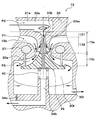
このエジェクタ13の具体的構成については、図2~図4を用いて説明する。なお、図2における上下の各矢印は、エジェクタ式冷凍サイクル10を車両用空調装置に搭載した状態における上下の各方向を示している。また、図3は、エジェクタ13の各冷媒通路の機能を説明するための模式的な断面図であって、図2と同一の機能を果たす部分には同一の符号を付している。
まず、本実施形態のエジェクタ13は、図2に示すように、複数の構成部材を組み合わせることによって構成されたボデー30を備えている。具体的には、ボデー30は、角柱状あるいは円柱状の金属もしくは樹脂にて形成されてエジェクタ13の外殻を形成するハウジングボデー31を有している。さらに、ハウジングボデー31の内部には、ノズルボデー32、ミドルボデー33、ロワーボデー34が固定されている。
ハウジングボデー31には、放熱器12から流出した冷媒を内部へ流入させる冷媒流入口31a、蒸発器14から流出した冷媒を吸引する冷媒吸引口31b、ボデー30の内部に形成された気液分離空間30fにて分離された液相冷媒を蒸発器14の冷媒入口側へ流出させる液相冷媒流出口31c、および気液分離空間30fにて分離された気相冷媒を圧縮機11の吸入口側へ流出させる気相冷媒流出口31d等が形成されている。
さらに、本実施形態では、気液分離空間30fと液相冷媒流出口31cとを接続する液相冷媒通路に、蒸発器14へ流入させる冷媒を減圧させる減圧装置としてのオリフィス30iを配置している。
ノズルボデー32は、冷媒流れ方向に先細る略円錐形状の金属部材で形成されている。さらに、ノズルボデー32は、軸方向が鉛直方向(図2の上下方向)となるように、ハウジングボデー31の内部に圧入等の手段によって固定されている。ノズルボデー32の上方側とハウジングボデー31との間には、冷媒流入口31aから流入した冷媒を旋回させる旋回空間30aが形成されている。
旋回空間30aは、回転体形状に形成され、図2の一点鎖線で示す中心軸が鉛直方向に延びている。なお、回転体形状とは、平面図形を同一平面上の1つの直線(中心軸)の周りに回転させた際に形成される立体形状である。より具体的には、本実施形態の旋回空間30aは、略円柱状に形成されている。もちろん、円錐あるいは円錐台と円柱とを結合させた形状等に形成されていてもよい。
冷媒流入口31aと旋回空間30aとを接続する冷媒流入通路31eは、旋回空間30aの中心軸方向から見たときに旋回空間30aの内壁面の接線方向に延びている。これにより、冷媒流入通路31eから旋回空間30aへ流入した冷媒は、旋回空間30aの内壁面に沿って流れ、旋回空間30aの中心軸周りに旋回する。
ここで、旋回空間30a内で旋回する冷媒には遠心力が作用するので、旋回空間30a内では中心軸側の冷媒圧力が外周側の冷媒圧力よりも低下する。そこで、本実施形態では、エジェクタ式冷凍サイクル10の通常運転時に、旋回空間30a内の中心軸側の冷媒圧力を、飽和液相冷媒となる圧力、あるいは、冷媒が減圧沸騰する(キャビテーションを生じる)圧力となるまで低下させるようにしている。
このような旋回空間30a内の中心軸側の冷媒圧力の調整は、旋回空間30a内で旋回する冷媒の旋回流速を調整することによって実現することができる。さらに、旋回流速の調整は、例えば、冷媒流入通路31eの通路断面積と旋回空間30aの軸方向垂直断面積との面積比を調整すること等によって行うことができる。なお、本実施形態の旋回流速とは、旋回空間30aの最外周部近傍における冷媒の旋回方向の流速を意味している。
また、ノズルボデー32の内部には、旋回空間30aから流出した冷媒を減圧させて下流側へ流出させる減圧用空間30bが形成されている。この減圧用空間30bは、円柱状空間とこの円柱状空間の下方側から連続して冷媒流れ方向に向かって徐々に広がる円錐台形状空間とを結合させた回転体形状に形成されており、減圧用空間30bの中心軸は旋回空間30aの中心軸と同軸上に配置されている。
さらに、減圧用空間30bの内部には、減圧用空間30b内に冷媒通路の通路断面積が最も縮小した最小通路面積部30mを形成するとともに、最小通路面積部30mの通路断面積を変化させる通路形成部材35が配置されている。
通路形成部材35は、冷媒流れ下流側に向かって徐々に広がる略円錐形状に形成されており、その中心軸が減圧用空間30bの中心軸と同軸上に配置されている。つまり、通路形成部材35は、減圧用空間30b側から離れるに伴って断面積が拡大する円錐状に形成されている。なお、通路形成部材35の詳細構成については後述する。
従って、ノズルボデー32の減圧用空間30bを形成する部位の内周面と通路形成部材35の上方側の外周面との間に形成される冷媒通路としては、図3に示すように、先細部131および末広部132が形成される。先細部131は、最小通路面積部30mよりも冷媒流れ上流側に形成されて、最小通路面積部30mに至るまでの通路断面積が徐々に縮小する冷媒通路である。末広部132は、最小通路面積部30mから冷媒流れ下流側に形成されて、通路断面積が徐々に拡大する冷媒通路である。
この末広部132では、径方向から見たときに減圧用空間30bと通路形成部材35が重合(オーバーラップ)しているので、冷媒通路の軸方向垂直断面の形状が円環状(円形状から同軸上に配置された小径の円形状を除いたドーナツ形状)となる。さらに、末広部132における通路断面積は、冷媒流れ下流側に向かって徐々に拡大している。
本実施形態では、このような通路形状によって減圧用空間30bの内周面と通路形成部材35の頂部側の外周面との間に形成される冷媒通路をラバールノズルとして機能するノズル通路13aとし、冷媒を減圧させるとともに、冷媒の流速を超音速となるように増速させて噴射している。
次に、ミドルボデー33は、図2に示すように、その中心部に表裏(上下)を貫通する貫通穴が設けられている。さらに、ミドルボデー33は、この貫通穴の外周側に通路形成部材35を変位させる駆動機構37を収容した金属製円板状部材で形成されている。なお、ミドルボデー33の貫通穴の中心軸は旋回空間30aおよび減圧用空間30bの中心軸と同軸上に配置されている。また、ミドルボデー33は、ハウジングボデー31の内部であって、かつ、ノズルボデー32の下方側に圧入等の手段によって固定されている。
さらに、ミドルボデー33の上面とこれに対向するハウジングボデー31の内壁面との間には、冷媒吸引口31bから流入した冷媒を滞留させる流入空間30cが形成されている。本実施形態では、ノズルボデー32の下方側の先細先端部がミドルボデー33の貫通穴の内部に位置付けられるため、流入空間30cは、旋回空間30aおよび減圧用空間30bの中心軸方向からみたときに、断面円環状に形成される。
また、ミドルボデー33の貫通穴のうち、ノズルボデー32の下方側が挿入される範囲、すなわち軸線に垂直な径方向から見たときにミドルボデー33とノズルボデー32が重合する範囲では、ノズルボデー32の先細先端部の外周形状に適合するように冷媒通路断面積が冷媒流れ方向に向かって徐々に縮小している。
これにより、貫通穴の内周面とノズルボデー32の下方側の外周面との間には、流入空間30cと減圧用空間30bの冷媒流れ下流側とを連通させる吸引通路30dが形成される。つまり、本実施形態では、流入空間30cおよび吸引通路30dによって、中心軸の外周側から内周側へ向かって吸引冷媒が流れる吸引用通路13bが形成されることになる。この吸引用通路13bの中心軸垂直断面も断面円環状に形成される。
また、ミドルボデー33の貫通穴のうち、吸引通路30dの冷媒流れ下流側には、冷媒流れ方向に向かって徐々に広がる略円錐台形状に形成された昇圧用空間30eが形成されている。昇圧用空間30eは、上述したノズル通路13aから噴射された噴射冷媒と吸引通路30dから吸引された吸引冷媒とを混合させる空間である。昇圧用空間30eの中心軸は旋回空間30aおよび減圧用空間30bの中心軸と同軸上に配置されている。
昇圧用空間30eの内部には、通路形成部材35の下方側が配置されている。さらに、ミドルボデー33の昇圧用空間30eを形成する部位の内周面と通路形成部材35の下方側の外周面との間に形成される冷媒通路は、冷媒流れ下流側に向かって通路断面積を徐々に拡大させる形状に形成されている。これにより、この冷媒通路では、噴射冷媒および吸引冷媒の混合冷媒の速度エネルギを圧力エネルギに変換させることができる。
従って、昇圧用空間30eを形成するミドルボデー33の内周面と通路形成部材35の下方側の外周面との間に形成される冷媒通路は、図3に示すように、噴射冷媒および吸引冷媒を混合して昇圧させるディフューザ(昇圧部)として機能するディフューザ通路13cを構成している。このディフューザ通路13cの中心軸垂直断面形状も円環状に形成される。
次に、ミドルボデー33の内部に配置されて、通路形成部材35を変位させる駆動装置である駆動機構37について説明する。この駆動機構37は、圧力応動部材である円形薄板状のダイヤフラム37aを有して構成されている。より具体的には、図2に示すように、ダイヤフラム37aはミドルボデー33の外周側に形成された円柱状の空間を上下の2つの空間に仕切るように、溶接等の手段によって固定されている。
ダイヤフラム37aによって仕切られた2つの空間のうち上方側(流入空間30c側)の空間は、蒸発器14出口側冷媒(具体的には、蒸発器14から流出した冷媒)の温度に応じて圧力変化する感温媒体が封入される封入空間37bを構成している。この封入空間37bには、エジェクタ式冷凍サイクル10を循環する冷媒と同等の組成の感温媒体が予め定めた密度となるように封入されている。従って、本実施形態における感温媒体は、R134aを主成分とする媒体である。
一方、ダイヤフラム37aによって仕切られた2つの空間のうち下方側の空間は、図示しない連通路を介して、蒸発器14出口側冷媒を導入させる導入空間37cを構成している。従って、封入空間37bに封入された感温媒体には、流入空間30cと封入空間37bとを仕切る蓋部材37dおよびダイヤフラム37aを介して、蒸発器14出口側冷媒の温度が伝達される。
さらに、ダイヤフラム37aは、封入空間37bの内圧と導入空間37cへ流入した蒸発器14出口側冷媒の圧力との差圧に応じて変形する。このため、ダイヤフラム37aは弾性に富み、かつ熱伝導が良好で、強靱な材質にて形成することが好ましい。従って、ダイヤフラム37aとして、ステンレス(SUS304)等の金属薄板を採用してもよいし、耐圧性およびシール性に優れる基布入りEPDM(エチレンプロピレンジエン共重合ゴム)等のゴム製のものを採用してもよい。
また、ダイヤフラム37aの中心部には、円柱状の作動棒37eの上端側が溶接等の手段によって接合され、作動棒37eの下端側には通路形成部材35の最下方部(底部)の外周側が固定されている。これにより、ダイヤフラム37aと通路形成部材35が連結され、ダイヤフラム37aの変位に伴って通路形成部材35が変位し、ノズル通路13aの最小通路面積部30mにおける通路断面積が調整される。
より具体的には、蒸発器14出口側冷媒の温度(過熱度)が上昇すると、封入空間37bに封入された感温媒体の飽和圧力が上昇し、封入空間37bの内圧から導入空間37cの圧力を差し引いた差圧が大きくなる。これにより、ダイヤフラム37aは、最小通路面積部30mにおける通路断面積を拡大させる方向(鉛直方向下方側)に通路形成部材35を変位させる。
一方、蒸発器14出口側冷媒の温度(過熱度)が低下すると、封入空間37bに封入された感温媒体の飽和圧力が低下して、封入空間37bの内圧から導入空間37cの圧力を差し引いた差圧が小さくなる。これにより、ダイヤフラム37aは、最小通路面積部30mにおける通路断面積を縮小させる方向(鉛直方向上方側)に通路形成部材35を変位させる。
このように蒸発器14出口側冷媒の過熱度に応じてダイヤフラム37aが通路形成部材35を変位させることによって、蒸発器14出口側冷媒の過熱度が予め定めた基準過熱度KSHに近づくように、最小通路面積部30mにおける通路断面積が調整される。なお、作動棒37eとミドルボデー33との隙間は、図示しないO-リング等のシール部材によってシールされており、作動棒37eが変位してもこの隙間から冷媒が漏れることはない。
また、通路形成部材35の底面は、ロワーボデー34に固定されたコイルバネ40の荷重を受けている。コイルバネ40は、通路形成部材35に対して、通路形成部材35が最小通路面積部30mにおける通路断面積を縮小する側に付勢する荷重を加える弾性部材である。この荷重を調整することで、通路形成部材35の開弁圧を変更して、狙いの基準過熱度KSHを変更することができる。
本実施形態では、ミドルボデー33の外周側に複数(具体的には2つ)の円柱状の空間を設け、この空間の内部にそれぞれ円形薄板状のダイヤフラム37aを固定して2つの駆動機構37を構成しているが、駆動機構37の数はこれに限定されない。なお、駆動機構37を複数箇所に設ける場合は、それぞれ中心軸に対して等角度間隔で配置されていることが望ましい。
また、軸方向からみたときに円環状に形成される空間内に、円環状の薄板で形成されたダイヤフラムを固定し、複数の作動棒でこのダイヤフラムと通路形成部材35とを連結する構成としてもよい。
次に、ロワーボデー34は、円柱状の金属部材で形成されており、ハウジングボデー31の底面を閉塞するように、ハウジングボデー31内にネジ止め等の手段によって固定されている。ロワーボデー34の上方側とミドルボデー33との間には、昇圧用空間30e内に形成されたディフューザ通路13cから流出した冷媒の気液を分離する気液分離空間30fが形成されている。
この気液分離空間30fは、略円柱状の回転体形状の空間として形成されており、気液分離空間30fの中心軸も、旋回空間30a、減圧用空間30b、昇圧用空間30e等の中心軸と同軸上に配置されている。さらに、ディフューザ通路13cから気液分離空間30fへ流出する冷媒は、中心軸周りに旋回する旋回方向の速度成分を有している。従って、気液分離空間30f内では遠心力の作用によって冷媒の気液が分離される。
さらに、この気液分離空間30fの内容積は、サイクルに負荷変動が生じてサイクルを循環する冷媒循環流量が変動しても、実質的に余剰冷媒を溜めることができない程度の容積になっている。
ロワーボデー34の中心部には、気液分離空間30fに対して同軸上に配置されて、上方側へ向かって延びる円筒状のパイプ34aが設けられている。そして、気液分離空間30fにて分離された液相冷媒は、パイプ34aの外周側に一時的に滞留して、液相冷媒流出口31cから流出する。パイプ34aの内部には、気液分離空間30fにて分離された気相冷媒をハウジングボデー31の気相冷媒流出口31dへ導く気相冷媒流出通路34bが形成されている。
パイプ34aの上端部には、前述したコイルバネ40固定されている。コイルバネ40は、通路形成部材35、および駆動機構37とともに、振動系を形成しており、冷媒が減圧される際の圧力脈動に起因する通路形成部材35の振動を減衰させる機能も有している。また、ロワーボデー34の底面には、液相冷媒中の冷凍機油を気相冷媒流出通路34bを介して圧縮機11内へ戻すオイル戻し穴34cが形成されている。
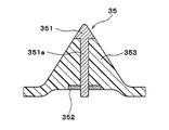
ここで、図4を用いて、本実施形態の通路形成部材35の詳細構成について説明する。本実施形態の通路形成部材35は、金属(本実施形態では、ステンレス合金)で形成された金属部(第1部材の一例)、および樹脂(本実施形態では、ポリフェニレンスルファイド(一般的略称:PPS))にて形成された樹脂部(第2部材の一例)を有している。さらに、金属部および樹脂部は、インサート成形されることによって、一体的に形成されている。
本実施形態の金属部としては、通路形成部材35の頂部側に配置された頂部側円錐状部材351、およびコイルバネ40が当接する部位に配置された円環状の板状部材352が設けられている。また、樹脂部としては、頂部側円錐状部材351の底面に配置された底部側円錐台状部材353が設けられている。
頂部側円錐状部材351は、通路形成部材35のうち、ノズル通路13aを形成する部位の外周面であって、少なくとも最小通路面積部30mを形成する部位を含む外周面を形成できる程度の大きさに形成されている。
より具体的には、本実施形態の通路形成部材35では、中心軸に垂直な方向からみたときに、減圧用空間30bの内部に配置される部位が頂部側円錐状部材351によって形成されている。これにより、通路形成部材35の円錐状側面のうち、最小通路面積部30mを形成する部位が確実に金属部で形成されるようにしている。
なお、本実施形態のノズル通路13aは、図3に示すように、通路形成部材35の外周面から法線方向に延びる線分がノズルボデー32のうち減圧用空間30bを形成する部位と交わる範囲に形成されるものとする。
さらに、頂部側円錐状部材351の底面には、底部側円錐台状部材353の底面側へ向かって延びる金属製の延設部351aが設けられている。延設部351aは、インサート成形時の金属部と樹脂部との接合面積を拡大させて、金属部と樹脂部との接合強度を向上させる機能を果たす。
より具体的には、本実施形態の延設部351aは、通路形成部材35と同軸上に配置された円柱状に形成されており、頂部側円錐状部材351の底面に一体的に形成されている。さらに、延設部351aは、金属部と樹脂部との接合面積を拡大させることができれば別の形状であってもよい。
また、エジェクタ13の液相冷媒流出口31cには、図1に示すように、蒸発器14の冷媒入口側が接続されている。蒸発器14は、エジェクタ13にて減圧された低圧冷媒と送風ファン14aから車室内へ送風される送風空気とを熱交換させることによって、低圧冷媒を蒸発させて吸熱作用を発揮させる吸熱用熱交換器である。
送風ファン14aは、制御装置から出力される制御電圧によって回転数(送風空気量)が制御される電動式送風機である。蒸発器14の出口側には、エジェクタ13の冷媒吸引口31bが接続されている。さらに、エジェクタ13の気相冷媒流出口31dには圧縮機11の吸入側が接続されている。
次に、図示しない制御装置は、CPU、ROMおよびRAM等を含む周知のマイクロコンピュータとその周辺回路から構成される。この制御装置は、そのROM内に記憶された制御プログラムに基づいて各種演算、処理を行って、上述の各種電気式のアクチュエータ11、12d、14a等の作動を制御する。
また、制御装置には、車室内温度を検出する内気温センサ、外気温を検出する外気温センサ、車室内の日射量を検出する日射センサ、蒸発器14の吹出空気温度(蒸発器温度)を検出する蒸発器温度センサ、放熱器12出口側冷媒の温度を検出する出口側温度センサおよび放熱器12出口側冷媒の圧力を検出する出口側圧力センサ等の空調制御用のセンサ群が接続され、これらのセンサ群の検出値が入力される。
さらに、制御装置の入力側には、車室内前部の計器盤付近に配置された図示しない操作パネルが接続され、この操作パネルに設けられた各種操作スイッチからの操作信号が制御装置へ入力される。操作パネルに設けられた各種操作スイッチとしては、車室内空調を行うことを要求する空調作動スイッチ、車室内温度を設定する車室内温度設定スイッチ等が設けられている。
なお、本実施形態の制御装置は、その出力側に接続された各種の制御対象機器の作動を制御する制御部が一体に構成されたものであるが、制御装置のうち、各制御対象機器の作動を制御する構成(ハードウェアおよびソフトウェア)が各制御対象機器の制御部を構成している。例えば、本実施形態では、圧縮機11の電動モータの作動を制御する構成が吐出能力制御部を構成している。
次に、上記構成における本実施形態の作動を図5のモリエル線図を用いて説明する。図5のモリエル線図の縦軸には、図3のP0、P1、P2に対応する圧力が示されている。まず、操作パネルの作動スイッチが投入(ON)されると、制御装置が圧縮機11の電動モータ、冷却ファン12d、送風ファン14a等を作動させる。これにより、圧縮機11が冷媒を吸入し、圧縮して吐出する。
圧縮機11から吐出された高温高圧冷媒(図5のa5点)は、放熱器12の凝縮部12aへ流入し、冷却ファン12dから送風された外気と熱交換し、放熱して凝縮する。凝縮部12aにて凝縮した冷媒は、レシーバ部12bにて気液分離される。レシーバ部12bにて気液分離された液相冷媒は、過冷却部12cにて冷却ファン12dから送風された外気と熱交換し、さらに放熱して過冷却液相冷媒となる(図5のa5点→b5点)。
放熱器12の過冷却部12cから流出した過冷却液相冷媒は、エジェクタ13の減圧用空間30bの内周面と通路形成部材35の外周面との間に形成されるノズル通路13aにて等エントロピ的に減圧されて噴射される(図5のb5点→c5点)。この際、減圧用空間30bの最小通路面積部30mにおける通路断面積は、蒸発器14出口側冷媒(図5のh5点)の過熱度が予め定めた所定値に近づくように調整される。
そして、ノズル通路13aから噴射された噴射冷媒の吸引作用によって、蒸発器14から流出した冷媒(図5のh5点)が、冷媒吸引口31bおよび吸引用通路13b(より詳細には、流入空間30cおよび吸引通路30d)を介して吸引される。ノズル通路13aから噴射された噴射冷媒および吸引通路13d等を介して吸引された吸引冷媒は、ディフューザ通路13cへ流入して合流する(図5のc5点→d5点、h’5点→d5点)。
ここで、吸引通路30dは、通路断面積が徐々に縮小する形状に形成されている。このため、吸引通路30dを通過する吸引冷媒は、その圧力を低下させながら(図5のh5点→h’5点)、流速を増加させる。これにより、吸引冷媒と噴射冷媒との速度差を縮小し、ディフューザ通路13cにて吸引冷媒と噴射冷媒が混合する際のエネルギ損失(混合損失)を減少させることができる。
ディフューザ通路13cでは冷媒通路断面積の拡大により、冷媒の運動エネルギが圧力エネルギに変換される。これにより、噴射冷媒と吸引冷媒が混合されながら混合冷媒の圧力が上昇する(図5のd5点→e5点)。ディフューザ通路13cから流出した冷媒は気液分離空間30fにて気液分離される(図5のe5点→f5点、e5点→g5点)。
気液分離空間30fにて分離された液相冷媒は、オリフィス30iにて減圧されて(図5のg5点→g’5点)、蒸発器14へ流入する。蒸発器14へ流入した冷媒は、送風ファン14aによって送風された送風空気から吸熱して蒸発する(図5のg’5点→h5点)。これにより、送風空気が冷却される。
一方、気液分離空間30fにて分離された気相冷媒は気相冷媒流出口31dから流出して、圧縮機11へ吸入され再び圧縮される(図5のf5点→a5点)。
本実施形態のエジェクタ式冷凍サイクル10は、以上の如く作動して、車室内へ送風される送風空気を冷却することができる。
この際、本実施形態のエジェクタ式冷凍サイクル10では、ディフューザ通路13cにて昇圧された冷媒を圧縮機11へ吸入させている。従って、エジェクタ式冷凍サイクル10によれば、蒸発器における冷媒蒸発圧力と圧縮機吸入冷媒の圧力が略同等となる通常の冷凍サイクル装置よりも、圧縮機11の消費動力を低減させて、サイクルの成績係数(COP)を向上させることができる。
また、本実施形態のエジェクタ13によれば、旋回空間30aにて冷媒を旋回させることで、旋回空間30a内の旋回中心側の冷媒圧力を、飽和液相冷媒となる圧力、あるいは、冷媒が減圧沸騰する(キャビテーションを生じる)圧力まで低下させることができる。これにより、旋回中心軸の外周側よりも内周側に気相冷媒が多く存在するようにして、旋回空間30a内の旋回中心線近傍はガス単相、その周りは液単相の二相分離状態とすることができる。
このように二相分離状態となった冷媒がノズル通路13aへ流入することで、ノズル通路13aの先細部131では、円環状の冷媒通路の外周側壁面から冷媒が剥離する際に生じる壁面沸騰および円環状の冷媒通路の中心軸側の冷媒のキャビテーションによって生じた沸騰核による界面沸騰によって冷媒の沸騰が促進される。これにより、ノズル通路13aの最小通路面積部30mへ流入する冷媒が、気相と液相が均質に混合した気液混合状態となる。
そして、最小通路面積部30mの近傍で気液混合状態の冷媒の流れに閉塞(チョーキング)が生じ、このチョーキングによって音速に到達した気液混合状態の冷媒が末広部132にて加速されて噴射される。このように、壁面沸騰および界面沸騰の双方による沸騰促進によって、気液混合状態の冷媒を音速となるまで効率よく加速できることで、ノズル通路13aにおけるエネルギ変換効率を向上させることができる。
また、本実施形態のエジェクタ13では、駆動機構37を備えているので、エジェクタ式冷凍サイクル10の負荷変動に応じて通路形成部材35を変位させて、ノズル通路13aの通路断面積(最小通路面積部30mにおける通路断面積)を調整することができる。これにより、サイクルを循環する冷媒の循環流量に応じて、最小通路面積部30mにおける通路断面積を適切に変化させて、エジェクタ13を適切に作動させることができる。
さらに、本実施形態の通路形成部材35は、樹脂部(底部側円錐台状部材353)を有しているので、全ての部位が金属で形成されたものよりも軽量化を図ることができる。これにより、通路形成部材35を含む振動系の共振周波数を比較的高い周波数とすることができる。従って、通路形成部材35を含む振動系が、車両振動に共振して、大きな騒音や振動を生じさせてしまうことを抑制することができる。
ここで、本実施形態のエジェクタ13のように、旋回空間30aにて冷媒を旋回させて二相分離状態とした冷媒をノズル通路13aへ流入させる構成では、気液界面におけるキャビテーションや、最小通路面積部30mにおける減圧によるキャビテーションが生じる。そして、キャビテーションによって生じた冷媒の気泡が、高速度で最小通路面積部30mを通過する。
このため、通路形成部材35の外周面(特に、最小通路面積部30mを形成する部位の外周面)にキャビテーションエロージョン(壊食)が生じて、通路形成部材35の外周面に損傷や変形を生じさせてしまうおそれがある。そして、通路形成部材35の外周面に損傷や変形が生じてしまうと、エジェクタ式冷凍サイクル10の負荷変動に応じて駆動機構37が通路形成部材35を変位させても、最小通路面積部30mにおける通路断面積を適切に変化させることができなくなってしまう。
これに対して、本実施形態のエジェクタ13では、金属部として、頂部側円錐状部材351が設けられているので、通路形成部材35の外周面のうち、通路形成部材35の最小通路面積部30mを形成する部位を含む外周面を金属とすることができる。従って、通路形成部材35の最小通路面積部30mを形成する部位の損傷や変形を抑制することができる。
これに加えて、一般的に、金属は樹脂よりも線膨張係数が小さいので、最小通路面積部30mにおける通路断面積が、温度変化によって変化してしまうことを抑制することができる。さらに、通路形成部材35の最小通路面積部30mを形成する部位が、温度変化によって変形して、ノズルボデー32の減圧用空間30bを形成する部位に噛みこんでしまうことを抑制することができる。
また、本実施形態のエジェクタ13のように、通路形成部材35を適切に変位させるために、通路形成部材35に対して荷重をかけるコイルバネ40を備える構成では、通路形成部材35のうち、コイルバネ40に当接して、コイルバネ40からの荷重を受ける部位に損傷や変形を生じさせてしまうおそれがある。
そして、コイルバネ40に当接して荷重を受ける部位に損傷や変形が生じてしまうと、駆動機構37が通路形成部材35を変位させた際の変位量等が変化してしまい、エジェクタ式冷凍サイクル10の負荷変動に応じて、最小通路面積部30mにおける通路断面積を適切に変化させることができなくなってしまう。
これに対して、本実施形態のエジェクタ13では、金属部として、円環状の板状部材352が設けられているので、通路形成部材35のうち、コイルバネ40に当接して荷重を受ける部位を金属とすることができる。従って、通路形成部材35のコイルバネ40に当接して荷重を受ける部位の損傷や変形を抑制することができる。
その結果、本実施形態のエジェクタ13によれば、通路形成部材35の軽量化を図りつつ、ノズル通路13aの通路断面積を適切に調整することができる。延いては、通路形成部材35を含む振動系が車両振動に共振してしまうことを回避しつつ、エジェクタ式冷凍サイクル10の負荷変動に応じて、エジェクタ13を適切に作動させることができる。
なお、本実施形態では、通路形成部材35の金属部(頂部側円錐状部材351、円環状の板状部材352)および樹脂部(底部側円錐台状部材353)をインサート成形によって一体的に形成した例を説明したが、金属部と樹脂部とを一体化させる手段はこれに限定されない。
例えば、金属部と樹脂部とを接着することによって一体化してもよい。頂部側円錐状部材351に設けられた延設部351aを底部側円錐台状部材353に圧入することによって一体化してもよい。
さらに、図6の変形例に示すように、延設部351aに形成された雄ねじ部351bを、底部側円錐台状部材353に形成された雌ねじ部に締結することによって一体化してもよい。このように線膨張係数が小さい金属部に雄ねじ部351bを形成することで、温度変化によって、雄ねじ部351bの外周側に配置される樹脂部に損傷や割れが生じてしまうことを抑制することができる。
また、図7の変形例に示すように、延設部351aの下方側端部(頂部側円錐状部材351の反対側の端部)を底部側円錐台状部材353の底面から突出させ、突出した部位の外周側に円環状の板状部材352の内周側を圧入することによって固定してもよい。これによれば、頂部側円錐状部材351の底面と板状部材352との間に、底部側円錐台状部材353を挟み混むことによって、金属部と樹脂部とを一体化することができる。
(第2実施形態)
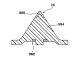
本実施形態では、第1実施形態に対して、通路形成部材35の構成を変更した例を説明する。本実施形態の通路形成部材35では、図8に示すように、樹脂部として、略円錐状に形成された円錐状部材354が設けられている。さらに、金属部として、第1実施形態と同様の円環状の板状部材352、および円錐状部材354の頂部側の側面を覆う円錐状カバー部材355が設けられている。
本実施形態では、第1実施形態に対して、通路形成部材35の構成を変更した例を説明する。本実施形態の通路形成部材35では、図8に示すように、樹脂部として、略円錐状に形成された円錐状部材354が設けられている。さらに、金属部として、第1実施形態と同様の円環状の板状部材352、および円錐状部材354の頂部側の側面を覆う円錐状カバー部材355が設けられている。
円錐状カバー部材355は、底面部を有しない中空の円錐形状に形成されており、通路形成部材35の外表面のうち、第1実施形態と同様の範囲の外表面を形成する程度の大きさに形成されている。さらに、本実施形態の樹脂部および金属部は、第1実施形態と同様の材料で形成されており、インサート成形されることによって、一体的に形成されている。
なお、図8は、第1実施形態の図4に対応する図面であって、第1実施形態と同一もしくは均等部分には同一の符号を付している。このことは、以下の図9、図10においても同様である。
その他のエジェクタ13およびエジェクタ式冷凍サイクル10の構成および作動は、第1実施形態と同様である。従って、本実施形態のエジェクタ13においても、第1実施形態と同様の効果を得ることができる。また、本実施形態の金属部および樹脂部についても、接着、圧入、ねじ締結等の手段によって一体化されていてもよい。
(第3実施形態)
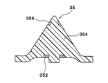
本実施形態では、第2実施形態の通路形成部材35に対して、さらに軽量化を狙った例を説明する。本実施形態の通路形成部材35では、図9に示すように、樹脂部として、第2実施形態と同様の円錐状部材354が設けられている。さらに、金属部として、第1実施形態と同様の円環状の板状部材352、および円錐状部材354の頂部側の側面を覆う円環状カバー部材356が設けられている。
本実施形態では、第2実施形態の通路形成部材35に対して、さらに軽量化を狙った例を説明する。本実施形態の通路形成部材35では、図9に示すように、樹脂部として、第2実施形態と同様の円錐状部材354が設けられている。さらに、金属部として、第1実施形態と同様の円環状の板状部材352、および円錐状部材354の頂部側の側面を覆う円環状カバー部材356が設けられている。
円環状カバー部材356は、上面部および底面部を有しない中空の円錐台形状に形成されており、通路形成部材35の外表面のうち、少なくとも最小通路面積部30mを形成する部位を含む外周面を形成できる程度の大きさに形成されている。このため、本実施形態の通路形成部材35の最頂部は、図9に示すように、樹脂製の円錐状部材354の頂部が減圧用空間30b内に露出している。
その他のエジェクタ13およびエジェクタ式冷凍サイクル10の構成および作動は、第2実施形態と同様である。従って、本実施形態のエジェクタ13においても、第1実施形態と同様の効果を得ることができる。
さらに、本実施形態では、円環状カバー部材356を採用しているので、金属部を減少させて、より一層、通路形成部材35全体としての軽量化を図ることができる。また、本実施形態の金属部および樹脂部についても、インサート成形、接着、圧入、ねじ締結等の手段によって一体化されていてもよい。
(第4実施形態)
本実施形態では、第2実施形態の通路形成部材35に対して、さらに軽量化を狙った例を説明する。本実施形態の通路形成部材35では、図10に示すように、樹脂部として、第2実施形態と同様の円錐状部材354が設けられている。さらに、金属部として、第1実施形態と同様の円環状の板状部材352、および円錐状部材354の円錐状側面を覆うようにメッキされた薄膜状カバー部材357が設けられている。
本実施形態では、第2実施形態の通路形成部材35に対して、さらに軽量化を狙った例を説明する。本実施形態の通路形成部材35では、図10に示すように、樹脂部として、第2実施形態と同様の円錐状部材354が設けられている。さらに、金属部として、第1実施形態と同様の円環状の板状部材352、および円錐状部材354の円錐状側面を覆うようにメッキされた薄膜状カバー部材357が設けられている。
なお、図10では、円錐状部材354の外周面のうち円錐状側面の略全域に薄膜状カバー部357を形成した例を示しているが、少なくとも通路形成部材35の最小通路面積部30mを形成する範囲を含む外周面に形成されていればよい。
その他のエジェクタ13およびエジェクタ式冷凍サイクル10の構成および作動は、第2実施形態と同様である。従って、本実施形態のエジェクタ13においても、第1実施形態と同様に、通路形成部材35の軽量化を図りつつ、内部に形成される冷媒通路の通路断面積を適切に調整することができる。
さらに、本実施形態では、薄膜状カバー部357を採用しているので、金属部を減少させて、より一層、通路形成部材35全体としての軽量化を図ることができる。また、本実施形態では、円錐状部材354に金属メッキを施すことによって、薄膜状カバー部材357を形成した例を説明したが、金属塗装によって薄膜状カバー部材357を形成してもよい。
(他の実施形態)
本開示は上述の実施形態に限定されることなく、本開示の趣旨を逸脱しない範囲内で、以下のように種々変形可能である。また、上記各実施形態に開示された手段は、実施可能な範囲で適宜組み合わせてもよい。
本開示は上述の実施形態に限定されることなく、本開示の趣旨を逸脱しない範囲内で、以下のように種々変形可能である。また、上記各実施形態に開示された手段は、実施可能な範囲で適宜組み合わせてもよい。
(1)上述の実施形態では、金属部として、通路形成部材35の最小通路面積部30mを形成する部位の損傷や変形を抑制するための金属部(頂部側円錐状部材351、各カバー部材355~357)、および通路形成部材35のコイルバネ40に当接して荷重を受ける部位の損傷や変形を抑制するための金属部(円環状の板状部材352)の双方を設けた例を説明したが、いずれか一方としてもよい。
(2)上述の第1実施形態では、頂部側円錐状部材351に延設部351aを設けた例を説明したが、金属部と樹脂部とを適切に接合可能であれば、延設部351aは必須の構成ではない。また、延設部351aを設ける場合には、延設部351aの下方側(頂部側円錐状部材351の反対側)に、円環状の板状部材352を圧入して固定してもよい。
(3)上記実施例の通路形成部材35では、第1材料よりなる第1部材(351、355、356、357)の一例として金属からなる金属部を用いて、および第1材料より密度が小さい第2材料よりなる第2部材(353、354)の一例として樹脂からなる樹脂部を用いている。しかし、第1材料の密度(単位体積あたりの質量)が、第2材料の密度(単位体積あたりの質量)より大きくすれば、第1部材と第2部材の材料は、金属と樹脂以外の材料でもよい。この場合,第1部材を構成する第1材料は、第2材料よりも強度的に強い材料にするのが望ましい。
例えば、第1材料は、アルミニウム又はSUSの少なくとも1種を主成分からなることでもよい。或いは/または、第2材料は、ポリフェニレンスルフィド(PPS GFxx、xxは数値)、ガラス繊維強化タイプのポリフェニレンスルフィド(PPS)、ポリアミド(PA)、ポリブチレンテレフタレート(PBT)、ポリイミド(PI)、ポリエーテルエーテルケトン(PEEK)の少なくとも1種を主成分からなってもよい。
(4)エジェクタ式冷凍サイクル10を構成する各構成機器は、上述の実施形態に開示されたものに限定されない。
例えば、上述の実施形態では、圧縮機11として、電動圧縮機を採用した例を説明したが、圧縮機11として、プーリ、ベルト等を介して車両走行用エンジンから伝達される回転駆動力によって駆動されるエンジン駆動式の圧縮機を採用してもよい。さらに、エンジン駆動式の圧縮機としては、吐出容量の変化により冷媒吐出能力を調整することのできる可変容量型圧縮機、あるいは電磁クラッチの断続により圧縮機の稼働率を変化させて冷媒吐出能力を調整する固定容量型圧縮機を採用することができる。
また、上述の実施形態では、放熱器12として、サブクール型の熱交換器を採用した例を説明したが、凝縮部12aのみからなる通常の放熱器を採用してもよい。さらに、通常の放熱器とともに、この放熱器にて放熱した冷媒の気液を分離して余剰液相冷媒を蓄える受液器(レシーバ)を一体化させたレシーバ一体型の凝縮器を採用してもよい。
また、上述の実施形態では、エジェクタ13の通路形成部材35を変位させる駆動装置として、駆動機構37を採用した例を説明したが、駆動装置はこれに限定されない。例えば、感温媒体として温度によって体積変化するサーモワックスを採用してもよい。さらに、駆動装置として形状記憶合金性の弾性部材を有して構成されたものを採用してもよいし、電動モータやソレノイド等の電気的機構によって通路形成部材35を変位させるものを採用してもよい。
また、上述の実施形態では、冷媒としてR134aあるいはR1234yf等を採用可能であることを説明したが、冷媒はこれに限定されない。例えば、R600a、R410A、R404A、R32、R1234yfxf、R407C等を採用することができる。または、これらの冷媒のうち複数種を混合させた混合冷媒等を採用してもよい。
(4)上述の実施形態では、本開示に係るエジェクタ式冷凍サイクル10を、車両用空調装置に適用した例を説明したが、エジェクタ式冷凍サイクル10の適用はこれに限定されない。例えば、据置型空調装置、冷温保存庫、自動販売機用冷却加熱装置等に適用してもよい。
また、上述の実施形態では、本開示に係るエジェクタ13を備えるエジェクタ式冷凍サイクル10の放熱器12を冷媒と外気とを熱交換させる室外側熱交換器とし、蒸発器14を送風空気を冷却する利用側熱交換器としている。これに対して、蒸発器14を外気等の熱源から吸熱する室外側熱交換器として用い、放熱器12を空気あるいは水等の被加熱流体を加熱する利用側熱交換器として用いてもよい。
Claims (13)
- 蒸気圧縮式の冷凍サイクル装置(10)に適用されるエジェクタであって、
冷媒流入口(31a)から流入した冷媒を減圧させる減圧用空間(30b)、前記減圧用空間(30b)の冷媒流れ下流側に連通して外部から吸引された冷媒を流通させる吸引用通路(13b)、前記減圧用空間(30b)から噴射された噴射冷媒と前記吸引用通路(13b)から吸引された吸引冷媒とを混合させる昇圧用空間(30e)が形成されたボデー(30)と、
少なくとも一部が前記減圧用空間(30b)の内部、および前記昇圧用空間(30e)の内部に配置されるとともに、前記減圧用空間(30b)側から離れるに伴って断面積が拡大する円錐状に形成された通路形成部材(35)と、
前記通路形成部材(35)を変位させる駆動装置(37)と、を備え、
前記ボデー(30)のうち前記減圧用空間(30b)を形成する部位の内周面と前記通路形成部材(35)の外周面との間に形成される冷媒通路は、前記冷媒流入口(31a)から流入した冷媒を減圧させて噴射するノズルとして機能するノズル通路(13a)であり、
前記ボデー(30)のうち前記昇圧用空間(30e)を形成する部位の内周面と前記通路形成部材(35)の外周面との間に形成される冷媒通路は、前記噴射冷媒および前記吸引冷媒を混合して昇圧させる昇圧部として機能するディフューザ通路(13c)であり、
前記通路形成部材(35)は、金属で形成された金属部(351、355、356、357)、および樹脂で形成された樹脂部(353、354)を有しており、
前記金属部は、前記ノズル通路(13a)を形成する部位の外周面であって、少なくとも前記ノズル通路(13a)の最小通路面積部(30m)を形成する部位を含む外周面を形成しているエジェクタ。 - 前記金属部として、前記通路形成部材(35)の頂部側に配置された頂部側円錐状部材(351)が設けられており、
前記樹脂部として、前記頂部側円錐状部材(351)の底面側に配置された底部側円錐台状部材(353)が設けられていることを特徴とする請求項1に記載のエジェクタ。 - 前記頂部側円錐状部材(351)の底面には、前記底部側円錐台状部材(353)の底面側へ向かって延びる延設部(351a)が設けられていることを特徴とする請求項2に記載のエジェクタ。
- 前記樹脂部として、円錐状に形成された円錐状部材(354)が設けられており、
前記金属部として、前記円錐状部材(354)の側面の少なくとも一部を覆うカバー部材(355、356、357)が設けられていることを特徴とする請求項1に記載のエジェクタ。 - 前記金属部(351、351a)および前記樹脂部(353)は、前記金属部(351a)に形成された雄ねじ部(351b)および前記樹脂部(353、354)に設けられた雌ねじ部が締結されることによって、一体化されていることを特徴とする請求項1ないし4のいずれか1つに記載のエジェクタ。
- 前記通路形成部材(35)に対して荷重を加える弾性部材(40)を備え、
前記金属部(352)は、前記通路形成部材(35)の前記弾性部材(40)が当接する部位に配置されていることを特徴とする請求項1ないし5のいずれか1つに記載のエジェクタ。 - 蒸気圧縮式の冷凍サイクル装置(10)に適用されるエジェクタであって、
冷媒流入口(31a)から流入した冷媒を減圧させる減圧用空間(30b)、前記減圧用空間(30b)の冷媒流れ下流側に連通して外部から吸引された冷媒を流通させる吸引用通路(13b)、前記減圧用空間(30b)から噴射された噴射冷媒と前記吸引用通路(13b)から吸引された吸引冷媒とを混合させる昇圧用空間(30e)が形成されたボデー(30)と、
少なくとも一部が前記減圧用空間(30b)の内部、および前記昇圧用空間(30e)の内部に配置されるとともに、前記減圧用空間(30b)側から離れるに伴って断面積が拡大する円錐状に形成された通路形成部材(35)と、
前記通路形成部材(35)に対して荷重を加える弾性部材(40)と、を備え、
前記ボデー(30)のうち前記減圧用空間(30b)を形成する部位の内周面と前記通路形成部材(35)の外周面との間に形成される冷媒通路は、前記冷媒流入口(31a)から流入した冷媒を減圧させて噴射するノズルとして機能するノズル通路(13a)であり、
前記ボデー(30)のうち前記昇圧用空間(30e)を形成する部位の内周面と前記通路形成部材(35)の外周面との間に形成される冷媒通路は、前記噴射冷媒および前記吸引冷媒を混合して昇圧させる昇圧部として機能するディフューザ通路(13c)であり、
前記通路形成部材(35)は、金属で形成された金属部(352)、および樹脂で形成された樹脂部(353、354)を有しており、
前記金属部(352)は、前記通路形成部材(35)の前記弾性部材(40)が当接する部位に配置されているエジェクタ。 - 前記弾性部材(40)は、コイルバネであり、
前記金属部は、円環状の板状部材(352)で形成されていることを特徴とする請求項7に記載のエジェクタ。 - 前記ボデー(30)には、前記冷媒流入口(31a)から流入した冷媒を旋回させて前記減圧用空間(30b)側へ流出させる旋回空間(30a)が形成されていることを特徴とする請求項1ないし8のいずれか1つに記載のエジェクタ。
- 蒸気圧縮式の冷凍サイクル装置(10)に適用されるエジェクタであって、
冷媒流入口(31a)から流入した冷媒を減圧させる減圧用空間(30b)、前記減圧用空間(30b)の冷媒流れ下流側に連通して外部から吸引された冷媒を流通させる吸引用通路(13b)、前記減圧用空間(30b)から噴射された噴射冷媒と前記吸引用通路(13b)から吸引された吸引冷媒とを混合させる昇圧用空間(30e)が形成されたボデー(30)と、
少なくとも一部が前記減圧用空間(30b)の内部、および前記昇圧用空間(30e)の内部に配置されるとともに、前記減圧用空間(30b)側から離れるに伴って断面積が拡大する円錐状に形成された通路形成部材(35)と、
前記通路形成部材(35)を変位させる駆動装置(37)と、を備え、
前記ボデー(30)のうち前記減圧用空間(30b)を形成する部位の内周面と前記通路形成部材(35)の外周面との間に形成される冷媒通路は、前記冷媒流入口(31a)から流入した冷媒を減圧させて噴射するノズルとして機能するノズル通路(13a)であり、
前記ボデー(30)のうち前記昇圧用空間(30e)を形成する部位の内周面と前記通路形成部材(35)の外周面との間に形成される冷媒通路は、前記噴射冷媒および前記吸引冷媒を混合して昇圧させる昇圧部として機能するディフューザ通路(13c)であり、
前記通路形成部材(35)は、第1材料よりなる第1部材(351、355、356、357)、および第1材料より密度が小さい第2材料よりなる第2部材(353、354)を有しており、
前記第1部材は、前記ノズル通路(13a)を形成する部位の外周面であって、少なくとも前記ノズル通路(13a)の最小通路面積部(30m)を形成する部位を含む外周面を形成しているエジェクタ。 - 前記第1部材を構成する第1材料は、第2材料よりも強度的に強いことを特徴とする請求項10に記載のエジェクタ。
- 前記第1材料は、アルミニウム又はSUSの少なくとも1種を主成分からなることを特徴とする請求項10または11に記載のエジェクタ。
- 前記第2材料は、ポリフェニレンスルフィド(PPS)、ガラス繊維強化タイプのポリフェニレンスルフィド(PPS)、ポリアミド(PA)、ポリブチレンテレフタレート(PBT)、ポリイミド(PI)、ポリエーテルエーテルケトン(PEEK)の少なくとも1種を主成分からなることを特徴とする請求項10ないし12のいずれか1つに記載のエジェクタ。
Applications Claiming Priority (2)
| Application Number | Priority Date | Filing Date | Title |
|---|---|---|---|
| JP2015-010231 | 2015-01-22 | ||
| JP2015010231A JP6380122B2 (ja) | 2015-01-22 | 2015-01-22 | エジェクタ |
Publications (1)
| Publication Number | Publication Date |
|---|---|
| WO2016117308A1 true WO2016117308A1 (ja) | 2016-07-28 |
Family
ID=56416863
Family Applications (1)
| Application Number | Title | Priority Date | Filing Date |
|---|---|---|---|
| PCT/JP2016/000172 Ceased WO2016117308A1 (ja) | 2015-01-22 | 2016-01-15 | エジェクタ |
Country Status (2)
| Country | Link |
|---|---|
| JP (1) | JP6380122B2 (ja) |
| WO (1) | WO2016117308A1 (ja) |
Families Citing this family (1)
| Publication number | Priority date | Publication date | Assignee | Title |
|---|---|---|---|---|
| WO2018105716A1 (ja) * | 2016-12-09 | 2018-06-14 | ダイキン工業株式会社 | ポリマー、組成物及び成形品 |
Citations (3)
| Publication number | Priority date | Publication date | Assignee | Title |
|---|---|---|---|---|
| JP2007257865A (ja) * | 2006-03-20 | 2007-10-04 | Aisin Seiki Co Ltd | 燃料電池スタック装置 |
| WO2014010162A1 (ja) * | 2012-07-09 | 2014-01-16 | 株式会社デンソー | エジェクタ |
| JP2014148970A (ja) * | 2013-01-11 | 2014-08-21 | Denso Corp | エジェクタ |
-
2015
- 2015-01-22 JP JP2015010231A patent/JP6380122B2/ja not_active Expired - Fee Related
-
2016
- 2016-01-15 WO PCT/JP2016/000172 patent/WO2016117308A1/ja not_active Ceased
Patent Citations (3)
| Publication number | Priority date | Publication date | Assignee | Title |
|---|---|---|---|---|
| JP2007257865A (ja) * | 2006-03-20 | 2007-10-04 | Aisin Seiki Co Ltd | 燃料電池スタック装置 |
| WO2014010162A1 (ja) * | 2012-07-09 | 2014-01-16 | 株式会社デンソー | エジェクタ |
| JP2014148970A (ja) * | 2013-01-11 | 2014-08-21 | Denso Corp | エジェクタ |
Also Published As
| Publication number | Publication date |
|---|---|
| JP6380122B2 (ja) | 2018-08-29 |
| JP2016133108A (ja) | 2016-07-25 |
Similar Documents
| Publication | Publication Date | Title |
|---|---|---|
| JP6048339B2 (ja) | エジェクタ | |
| JP6350108B2 (ja) | エジェクタ、およびエジェクタ式冷凍サイクル | |
| US9816738B2 (en) | Ejector | |
| JP6610313B2 (ja) | エジェクタ、エジェクタの製造方法、およびエジェクタ式冷凍サイクル | |
| JP6398802B2 (ja) | エジェクタ、およびエジェクタ式冷凍サイクル | |
| WO2014185069A1 (ja) | エジェクタ | |
| JP5962571B2 (ja) | エジェクタ | |
| WO2016143292A1 (ja) | エジェクタ式冷凍サイクル | |
| JP6511873B2 (ja) | エジェクタ、およびエジェクタ式冷凍サイクル | |
| WO2016143300A1 (ja) | エジェクタ、エジェクタの製造方法、およびエジェクタ式冷凍サイクル | |
| JP6380122B2 (ja) | エジェクタ | |
| JP2017089964A (ja) | エジェクタ式冷凍サイクル | |
| WO2016185664A1 (ja) | エジェクタ、およびエジェクタ式冷凍サイクル | |
| JP6399009B2 (ja) | エジェクタ、およびエジェクタ式冷凍サイクル | |
| WO2015015755A1 (ja) | エジェクタ | |
| JP6365408B2 (ja) | エジェクタ | |
| JP6011484B2 (ja) | エジェクタ | |
| JP6582950B2 (ja) | エジェクタ | |
| JP2017015346A (ja) | エジェクタ | |
| JP2016133084A (ja) | エジェクタ | |
| WO2017033724A1 (ja) | エジェクタ | |
| JP2017044207A (ja) | エジェクタ | |
| JP2017053574A (ja) | エジェクタ | |
| JP2017053290A (ja) | エジェクタ | |
| JP2017002872A (ja) | エジェクタ |
Legal Events
| Date | Code | Title | Description |
|---|---|---|---|
| 121 | Ep: the epo has been informed by wipo that ep was designated in this application |
Ref document number: 16739919 Country of ref document: EP Kind code of ref document: A1 |
|
| NENP | Non-entry into the national phase |
Ref country code: DE |
|
| 122 | Ep: pct application non-entry in european phase |
Ref document number: 16739919 Country of ref document: EP Kind code of ref document: A1 |