WO2016114300A1 - Support de joint d'étanchéité, structure de joint de bride, élément de positionnement de joint d'étanchéité, ensemble joint d'étanchéité et procédé de fabrication d'un ensemble joint d'étanchéité - Google Patents
Support de joint d'étanchéité, structure de joint de bride, élément de positionnement de joint d'étanchéité, ensemble joint d'étanchéité et procédé de fabrication d'un ensemble joint d'étanchéité Download PDFInfo
- Publication number
- WO2016114300A1 WO2016114300A1 PCT/JP2016/050823 JP2016050823W WO2016114300A1 WO 2016114300 A1 WO2016114300 A1 WO 2016114300A1 JP 2016050823 W JP2016050823 W JP 2016050823W WO 2016114300 A1 WO2016114300 A1 WO 2016114300A1
- Authority
- WO
- WIPO (PCT)
- Prior art keywords
- gasket
- flange
- positioning member
- center
- annular
- Prior art date
Links
Images


Classifications
-
- F—MECHANICAL ENGINEERING; LIGHTING; HEATING; WEAPONS; BLASTING
- F16—ENGINEERING ELEMENTS AND UNITS; GENERAL MEASURES FOR PRODUCING AND MAINTAINING EFFECTIVE FUNCTIONING OF MACHINES OR INSTALLATIONS; THERMAL INSULATION IN GENERAL
- F16J—PISTONS; CYLINDERS; SEALINGS
- F16J15/00—Sealings
- F16J15/02—Sealings between relatively-stationary surfaces
- F16J15/06—Sealings between relatively-stationary surfaces with solid packing compressed between sealing surfaces
-
- F—MECHANICAL ENGINEERING; LIGHTING; HEATING; WEAPONS; BLASTING
- F16—ENGINEERING ELEMENTS AND UNITS; GENERAL MEASURES FOR PRODUCING AND MAINTAINING EFFECTIVE FUNCTIONING OF MACHINES OR INSTALLATIONS; THERMAL INSULATION IN GENERAL
- F16L—PIPES; JOINTS OR FITTINGS FOR PIPES; SUPPORTS FOR PIPES, CABLES OR PROTECTIVE TUBING; MEANS FOR THERMAL INSULATION IN GENERAL
- F16L23/00—Flanged joints
- F16L23/003—Auxiliary devices
-
- F—MECHANICAL ENGINEERING; LIGHTING; HEATING; WEAPONS; BLASTING
- F16—ENGINEERING ELEMENTS AND UNITS; GENERAL MEASURES FOR PRODUCING AND MAINTAINING EFFECTIVE FUNCTIONING OF MACHINES OR INSTALLATIONS; THERMAL INSULATION IN GENERAL
- F16L—PIPES; JOINTS OR FITTINGS FOR PIPES; SUPPORTS FOR PIPES, CABLES OR PROTECTIVE TUBING; MEANS FOR THERMAL INSULATION IN GENERAL
- F16L23/00—Flanged joints
- F16L23/006—Attachments
-
- F—MECHANICAL ENGINEERING; LIGHTING; HEATING; WEAPONS; BLASTING
- F16—ENGINEERING ELEMENTS AND UNITS; GENERAL MEASURES FOR PRODUCING AND MAINTAINING EFFECTIVE FUNCTIONING OF MACHINES OR INSTALLATIONS; THERMAL INSULATION IN GENERAL
- F16L—PIPES; JOINTS OR FITTINGS FOR PIPES; SUPPORTS FOR PIPES, CABLES OR PROTECTIVE TUBING; MEANS FOR THERMAL INSULATION IN GENERAL
- F16L23/00—Flanged joints
- F16L23/16—Flanged joints characterised by the sealing means
- F16L23/18—Flanged joints characterised by the sealing means the sealing means being rings
Definitions
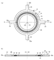
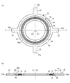
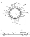
- a gasket holder is a gasket holder that holds an annular gasket disposed between two opposing flanges at a predetermined position with respect to the flange.
- An annular portion having an inner diameter capable of accommodating the gasket, and a plurality of projecting portions that project radially outward from the annular portion and are spaced apart in the circumferential direction of the annular portion. The length from the center of the annular portion to the tip of each protrusion corresponds to the flange from the center to the outer periphery.
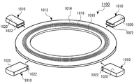
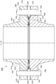
- the gasket assembly includes an annular gasket disposed between two opposing flanges, and a gasket positioning member for positioning the gasket at a predetermined position with respect to the flange.
- the gasket positioning member is composed of a plate-like piece, and a recess for attaching the gasket positioning member to the outer edge portion of the gasket is formed at one end of the plate-like piece. In a state where the gasket positioning member is attached to the outer edge of the gasket, the length from the center of the gasket to the other end of the plate-like piece corresponds to the length from the center of the flange to the outer peripheral edge.
- Still another aspect of the second embodiment is a gasket comprising an annular gasket disposed between two opposed flanges, and a gasket positioning member for positioning the gasket at a predetermined position with respect to the flange.
- This method comprises a step of preparing a gasket positioning member comprising a plate-like piece, wherein a gasket positioning member having a recess formed at one end of the plate-like piece for attaching itself to the outer edge of the gasket, and gasket positioning Attaching the member to the outer edge of the gasket.
- the length from the center of the gasket to the other end of the plate-like piece corresponds to the length from the center of the flange to the outer peripheral edge.
- the gasket positioning member 1010 By attaching the gasket positioning member 1010 to the gasket 1012 to constitute the gasket assembly 1100, the gasket 1012 can be easily attached at an accurate position.
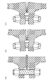
- the gasket positioning member 1010 is divided into two (first divided member 1010a and second divided member 1010b) at the center in the thickness direction.
- a first divided recess 1022a is formed at one end of the first divided member 1010a
- a second divided recess 1022b is formed at one end of the second divided member 1010b.
Landscapes
- Engineering & Computer Science (AREA)
- General Engineering & Computer Science (AREA)
- Mechanical Engineering (AREA)
- Gasket Seals (AREA)
Abstract
L'invention concerne un support de joint d'étanchéité (10) qui porte un joint d'étanchéité annulaire (12) dans une position prédéterminée par rapport à deux brides opposées, le joint d'étanchéité étant disposé entre les brides. Le support de joint d'étanchéité (10) est pourvu d'une partie annulaire (20) ayant un diamètre interne pouvant recevoir le joint d'étanchéité (12), et d'une pluralité de saillies (22) faisant saillie radialement vers l'extérieur à partir de la partie annulaire (20) et disposées par intervalles dans la direction périphérique de la partie annulaire (20). La longueur du centre de la partie annulaire (20) à une partie de pointe (22a) de chaque saillie (22) est équivalente à la longueur du centre au bord périphérique externe de chaque bride.
Applications Claiming Priority (4)
| Application Number | Priority Date | Filing Date | Title |
|---|---|---|---|
| JP2015004449A JP2016130549A (ja) | 2015-01-13 | 2015-01-13 | ガスケットホルダおよびフランジ継ぎ手構造 |
| JP2015-004450 | 2015-01-13 | ||
| JP2015004450A JP2016130550A (ja) | 2015-01-13 | 2015-01-13 | ガスケット位置決め部材、ガスケット組立体、フランジ継ぎ手構造およびガスケット組立体の製造方法 |
| JP2015-004449 | 2015-01-13 |
Publications (1)
| Publication Number | Publication Date |
|---|---|
| WO2016114300A1 true WO2016114300A1 (fr) | 2016-07-21 |
Family
ID=56405841
Family Applications (1)
| Application Number | Title | Priority Date | Filing Date |
|---|---|---|---|
| PCT/JP2016/050823 WO2016114300A1 (fr) | 2015-01-13 | 2016-01-13 | Support de joint d'étanchéité, structure de joint de bride, élément de positionnement de joint d'étanchéité, ensemble joint d'étanchéité et procédé de fabrication d'un ensemble joint d'étanchéité |
Country Status (1)
| Country | Link |
|---|---|
| WO (1) | WO2016114300A1 (fr) |
Citations (4)
| Publication number | Priority date | Publication date | Assignee | Title |
|---|---|---|---|---|
| JPH026889U (fr) * | 1988-06-28 | 1990-01-17 | ||
| JPH09508958A (ja) * | 1994-02-15 | 1997-09-09 | ダブリュ.エル.ゴア アンド アソシエイツ,インコーポレイティド | 立ち上がりフランジ用の容易に位置決め可能なガスケット |
| JP2007333065A (ja) * | 2006-06-14 | 2007-12-27 | Nippon Valqua Ind Ltd | 鋸歯形ガスケット |
| JP2011144870A (ja) * | 2010-01-14 | 2011-07-28 | Chiyoda Kako Kensetsu Kk | ガスケット |
-
2016
- 2016-01-13 WO PCT/JP2016/050823 patent/WO2016114300A1/fr active Application Filing
Patent Citations (4)
| Publication number | Priority date | Publication date | Assignee | Title |
|---|---|---|---|---|
| JPH026889U (fr) * | 1988-06-28 | 1990-01-17 | ||
| JPH09508958A (ja) * | 1994-02-15 | 1997-09-09 | ダブリュ.エル.ゴア アンド アソシエイツ,インコーポレイティド | 立ち上がりフランジ用の容易に位置決め可能なガスケット |
| JP2007333065A (ja) * | 2006-06-14 | 2007-12-27 | Nippon Valqua Ind Ltd | 鋸歯形ガスケット |
| JP2011144870A (ja) * | 2010-01-14 | 2011-07-28 | Chiyoda Kako Kensetsu Kk | ガスケット |
Similar Documents
| Publication | Publication Date | Title |
|---|---|---|
| EP2273164B1 (fr) | Joint mécanique fendu | |
| EP1767842B1 (fr) | Raccord pour tubes | |
| US20130097815A1 (en) | Profiled clamp with sealing element | |
| US4021128A (en) | Joint structure for modular shelf assembly | |
| US20200292113A1 (en) | Profile Clamp Comprising a Sealing Element, Sealing Element for a Profile Clamp and Conduit Connection Assembly Comprising a Profile Clamp of This Type | |
| JP2005308223A (ja) | カラーを有するピンを用いて部品をともに締め付けるためのファスナシステム | |
| WO2014031577A1 (fr) | Ensemble raccord de marteau, joint de raccord de marteau pour celui-ci et procédé de construction d'un joint de raccord de marteau | |
| US4184785A (en) | Axially bolted flange joint | |
| JP2017036806A (ja) | 軸継手 | |
| JP2012251583A (ja) | 部品締結構造 | |
| EP2610070B1 (fr) | Ensemble de roue de véhicule démontable, joint d'étanchéité destiné à être utilisé dans un tel ensemble de roue et procédé de fabrication d'un tel ensemble de roue | |
| US7467814B2 (en) | Flange | |
| JP2014118983A (ja) | 螺合金具離脱防止具及びクランプ装置 | |
| WO2016114300A1 (fr) | Support de joint d'étanchéité, structure de joint de bride, élément de positionnement de joint d'étanchéité, ensemble joint d'étanchéité et procédé de fabrication d'un ensemble joint d'étanchéité | |
| JP6962729B2 (ja) | 漏洩防止装置 | |
| JP2016130550A (ja) | ガスケット位置決め部材、ガスケット組立体、フランジ継ぎ手構造およびガスケット組立体の製造方法 | |
| JP2015137683A (ja) | フランジ接合部補強構造及びそれに用いられる環状保護部材 | |
| US20140035233A1 (en) | Mechanical seal | |
| US11009160B2 (en) | Joint assembly for fluid carrying pipes | |
| US10788153B2 (en) | Joint assembly for fluid carrying pipes | |
| WO2016021433A1 (fr) | Dispositif d'étanchéité | |
| JP3175094U (ja) | フランジ継手構造 | |
| JP2016130549A (ja) | ガスケットホルダおよびフランジ継ぎ手構造 | |
| KR20190084428A (ko) | 파이프 연결장치 | |
| US20220163148A1 (en) | Flexibly insertable profiled clamp |
Legal Events
| Date | Code | Title | Description |
|---|---|---|---|
| 121 | Ep: the epo has been informed by wipo that ep was designated in this application |
Ref document number: 16737371 Country of ref document: EP Kind code of ref document: A1 |
|
| NENP | Non-entry into the national phase |
Ref country code: DE |
|
| 122 | Ep: pct application non-entry in european phase |
Ref document number: 16737371 Country of ref document: EP Kind code of ref document: A1 |