WO2016114177A1 - 金属酸化物粒子の製造方法 - Google Patents
金属酸化物粒子の製造方法 Download PDFInfo
- Publication number
- WO2016114177A1 WO2016114177A1 PCT/JP2016/050146 JP2016050146W WO2016114177A1 WO 2016114177 A1 WO2016114177 A1 WO 2016114177A1 JP 2016050146 W JP2016050146 W JP 2016050146W WO 2016114177 A1 WO2016114177 A1 WO 2016114177A1
- Authority
- WO
- WIPO (PCT)
- Prior art keywords
- gas
- oxide particles
- temperature
- metal oxide
- combined
- Prior art date
- Legal status (The legal status is an assumption and is not a legal conclusion. Google has not performed a legal analysis and makes no representation as to the accuracy of the status listed.)
- Ceased
Links
Images

Classifications
-
- C—CHEMISTRY; METALLURGY
- C01—INORGANIC CHEMISTRY
- C01B—NON-METALLIC ELEMENTS; COMPOUNDS THEREOF; METALLOIDS OR COMPOUNDS THEREOF NOT COVERED BY SUBCLASS C01C
- C01B13/00—Oxygen; Ozone; Oxides or hydroxides in general
- C01B13/14—Methods for preparing oxides or hydroxides in general
- C01B13/20—Methods for preparing oxides or hydroxides in general by oxidation of elements in the gaseous state; by oxidation or hydrolysis of compounds in the gaseous state
- C01B13/22—Methods for preparing oxides or hydroxides in general by oxidation of elements in the gaseous state; by oxidation or hydrolysis of compounds in the gaseous state of halides or oxyhalides
-
- C—CHEMISTRY; METALLURGY
- C01—INORGANIC CHEMISTRY
- C01G—COMPOUNDS CONTAINING METALS NOT COVERED BY SUBCLASSES C01D OR C01F
- C01G23/00—Compounds of titanium
- C01G23/04—Oxides; Hydroxides
- C01G23/047—Titanium dioxide
- C01G23/07—Producing by vapour phase processes, e.g. halide oxidation
-
- B—PERFORMING OPERATIONS; TRANSPORTING
- B01—PHYSICAL OR CHEMICAL PROCESSES OR APPARATUS IN GENERAL
- B01J—CHEMICAL OR PHYSICAL PROCESSES, e.g. CATALYSIS OR COLLOID CHEMISTRY; THEIR RELEVANT APPARATUS
- B01J2235/00—Indexing scheme associated with group B01J35/00, related to the analysis techniques used to determine the catalysts form or properties
- B01J2235/15—X-ray diffraction
-
- B—PERFORMING OPERATIONS; TRANSPORTING
- B01—PHYSICAL OR CHEMICAL PROCESSES OR APPARATUS IN GENERAL
- B01J—CHEMICAL OR PHYSICAL PROCESSES, e.g. CATALYSIS OR COLLOID CHEMISTRY; THEIR RELEVANT APPARATUS
- B01J2235/00—Indexing scheme associated with group B01J35/00, related to the analysis techniques used to determine the catalysts form or properties
- B01J2235/30—Scanning electron microscopy; Transmission electron microscopy
Definitions
- the present invention relates to a method for producing metal oxide particles, and more particularly to a method for producing metal oxide particles for producing metal oxide particles for a long time without clogging a raw material gas flow path.
- the present invention claims priority based on Japanese Patent Application No. 2015-005149 filed in Japan on January 14, 2015, the contents of which are incorporated herein by reference.
- Patent Documents 1 and 2 and Non-Patent Documents 1 to 3 titanium oxide particles having a decahedral box shape and mainly composed of anatase crystals (hereinafter referred to as “decahedron titanium oxide particles”). Is disclosed. Patent Documents 1 and 2 and Non-Patent Documents 1 and 3 describe that decahedral titanium oxide particles have a large surface area per unit mass, high crystallinity, and few internal defects, and therefore have high activity as a photocatalyst. Has been.
- Non-Patent Document 2 describes that decahedral titanium oxide particles have a high ratio of (001) surfaces with high reactivity and are promising as photocatalysts.
- Non-Patent Document 2 As a method for producing decahedral titanium oxide particles, for example, there is a method utilizing hydrothermal reaction using hydrofluoric acid described in Non-Patent Document 2. However, since hydrofluoric acid has a strong acidity and is difficult to handle, the production method of Non-Patent Document 2 using this is not suitable for industrial use.
- TiCl 4 titanium tetrachloride
- O 2 oxygen
- the powder product containing a titanium oxide particle can be obtained in the downstream of a reaction tube.
- This powdery product contains a large amount of decahedral titanium oxide particles.
- the above-described production methods described in Patent Documents 1 and 2 and Non-Patent Documents 1 and 3 use titanium tetrachloride as a raw material when rapidly raising the temperature of the raw material gas to a temperature at which the thermal oxidation reaction of titanium tetrachloride proceeds. And oxygen gas is heated from the outside of the reaction tube.
- the flow rate of the raw material gas is large by joining titanium tetrachloride as a raw material in two stages with the preheated first gas and second gas and heating them. Even in this case, titanium oxide particles having a high photocatalytic activity can be produced in a high yield.
- the manufacturing method described in Patent Document 3 since at least one of the preheated titanium tetrachloride-containing gas and the preheated first gas contains oxygen, the titanium tetrachloride-containing gas is introduced.
- the glass is often broken because it is firmly fixed to the glass.
- the present invention has been made in view of the above circumstances, and an object thereof is to provide a method for producing metal oxide particles, in which metal oxide particles having high photocatalytic activity are produced for a long time.
- the metal chloride-containing gas containing the preheated metal chloride is combined with the first gas preheated at a temperature equal to or higher than the preheat temperature of the metal chloride-containing gas to heat the metal chloride-containing gas.
- the gas is further heated by combining the second gas preheated at a temperature higher than the temperature of the combined gas with the combined gas heated to a temperature higher than the preheating temperature of the metal chloride-containing gas.
- the inventors found that metal oxide particles having high photocatalytic activity can be produced for a long time by not containing oxygen and water vapor in both the metal chloride-containing gas and the first gas, and completed the following invention.
- the present invention employs the following configuration. That is, (1) In the reaction tube, the preheated metal chloride-containing gas is joined with the preheated first gas not containing the metal chloride at the first joining point to form the first joining gas, and the first joining gas Metal oxide particles including a step of joining the preheated second gas not containing the metal chloride at a second joining point farther downstream than the first joining point to form a second joining gas Both the metal chloride-containing gas and the first gas do not contain oxygen or water vapor, the second gas contains at least oxygen, and the preheating temperature of the first gas is increased.
- the first gas is joined at the first joining point at a temperature equal to or higher than the preheating temperature of the metal chloride-containing gas, so that the first joining point to the second joining point (referred to as a first zone). ),
- the pre-heated metal chloride-containing gas Are further heated, and the preheating temperature of the second gas is merged with the first merged gas as a temperature equal to or higher than the temperature of the first merged gas, so that the first merge is performed downstream from the second merge point.
- a method for producing metal oxide particles wherein the gas is further heated.
- a preheated first gas containing no metal chloride is joined to a preheated metal chloride-containing gas in a reaction tube at a first joining point.
- a second preheated gas that does not contain the metal chloride is joined to the first joining gas at a second joining point that is further downstream than the first joining point.
- a method for producing metal oxide particles, wherein both the metal chloride-containing gas and the first gas do not contain oxygen and water vapor, and the preheating temperature of the first gas is set to the metal chloride.
- the metal chloride-containing gas preheated between the first joining point and the second joining point is obtained by joining the first gas at the first joining point as a temperature equal to or higher than the preheating temperature of the contained gas.
- the preheating temperature of the second gas Metal oxidation with high photocatalytic activity is achieved by further heating the first combined gas downstream from the second combined point by combining the first combined gas with a temperature equal to or higher than the temperature of the first combined gas.
- Product particles can be produced for a long time.
- titanium tetrachloride is used as the metal chloride, and the metal oxide particles to be produced are titanium oxide particles, and also in this case, the metal chloride
- Both the contained gas and the first gas do not contain oxygen and water vapor, and the first gas is brought into the first merge with the preheating temperature of the first gas being equal to or higher than the preheating temperature of the metal chloride-containing gas.
- the metal chloride-containing gas preheated between the first merging point and the second merging point is further heated, and the preheating temperature of the second gas is changed to the first gas merging point.
- Titanium oxide particles having high photocatalytic activity can be obtained by further heating the first combined gas downstream from the second combined point by combining the first combined gas with a temperature equal to or higher than the temperature. A, it can be produced for a long time.
- the apparatus for producing metal oxide particles according to the present invention includes a reaction tube and a preheating unit for preheating each of the metal chloride-containing gas, the first gas, and the second gas, and the reaction tube has a hollow outer surface.
- a first conduit that introduces the first gas preheated upstream thereof, and the hollow outer cylinder is preheated upstream thereof.
- a second conduit for introducing the second gas, the preheated metal chloride-containing gas is introduced from the upstream side of the first hollow inner cylinder, and the introduced metal chloride-containing gas is the first gas
- the first gas preheated at the downstream end of the hollow inner cylinder merges, and the merged gas flows into the second hollow inner cylinder.
- FIG. 1 is a schematic view showing an example of a production apparatus used in the method for producing metal oxide particles according to an embodiment of the present invention.
- the manufacturing apparatus 101 used in the manufacturing method of the metal oxide particle which is embodiment of this invention is the hollow outer cylinder 1, and the hollow outer cylinder from the upstream (upstream part) 1a of the hollow outer cylinder 1.
- the second hollow inner cylinder 5 inserted to the middle of 1 and the first hollow inner cylinder 4 inserted from the upstream side 5a of the second hollow inner cylinder 5 to the middle of the second hollow inner cylinder 5 While having the reaction tube 11, the heat insulating material 2 is arrange
- the reaction tube 11 includes a hollow outer cylinder 1, a first hollow inner cylinder 4, and a second hollow inner cylinder 5.
- the reaction tube 11 is configured by a cylindrical tube made of, for example, quartz.
- the second hollow inner cylinder 5 is inserted partway from the upstream side 1 a of the hollow outer cylinder 1, and the downstream end 5 b is arranged so as to be near the center in the longitudinal direction of the hollow outer cylinder 1.
- the first hollow inner cylinder 4 is inserted partway from the upstream side 5 a of the second hollow inner cylinder 5, and the downstream end 4 b is disposed so as to be near the center in the longitudinal direction of the second hollow inner cylinder 5. ing.
- Metal chloride-containing gas The metal chloride-containing gas G1 preheated in the preheating region (preheating portion) X is poured into the first hollow inner cylinder opening 24 on the upstream side 4a of the first hollow inner cylinder 4.
- a vaporizer for evaporating a metal chloride such as titanium tetrachloride (TiCl 4 ) is installed on the upstream side of the preheating region X, and a liquid is installed on the upstream side of the vaporizer.
- An introduction pipe for introducing the metal chloride into the vaporizer and an introduction pipe for supplying a gas containing nitrogen are connected to the vaporizer through valves.
- the vaporizer has a function of evaporating a liquid metal chloride into a metal chloride vapor by setting the temperature to 165 ° C., for example. Thereby, it is set as the structure which can supply the metal chloride containing gas G1 which consists of mixed gas containing a metal chloride vapor
- the metal chloride-containing gas G1 is a gas containing a vapor such as titanium tetrachloride. Specifically, a mixed gas of a vapor such as titanium tetrachloride and nitrogen, or a mixed gas of a vapor such as titanium tetrachloride and an inert gas containing nitrogen can be used as the metal chloride-containing gas G1.
- the first gas G2 preheated in the preheating region (preheating portion) Y flows into the ring-shaped opening 25 between the downstream side 4b of the first hollow inner cylinder 4 and the upstream side 5a of the second hollow inner cylinder 5. It is.
- the first gas G2 is a gas containing no metal chloride such as titanium tetrachloride, oxygen, and water vapor.
- the first gas G2 is an inert gas such as nitrogen or argon, and these may be used alone or in combination. Therefore, a gas composed of only nitrogen, a gas composed of only argon, a mixed gas of nitrogen and an inert gas such as argon, or the like can be used.
- the second gas G3 is a gas that does not contain a metal chloride such as titanium tetrachloride. Specifically, the second gas G3 contains at least oxygen (O 2 ).
- the second gas G3 may contain oxygen, an inert gas such as nitrogen or argon, water vapor and ozone (O 3 ), or a mixture thereof. Accordingly, the second gas G3 is in a state of only oxygen, a state of a mixed gas of inert gas such as nitrogen or argon and oxygen, a state of a mixed gas of water vapor and oxygen, or a mixture of inert gas, water vapor and oxygen.
- the state of gas can be taken. Note that air may be used as a mixed gas of an inert gas and oxygen.
- the first hollow inner cylinder 4 and the second hollow inner cylinder 5 have a coaxial structure.
- the metal chloride-containing gas G1 can be collected on the central axis side, and the diffusion of titanium tetrachloride vapor to the inner wall surface of the second hollow inner cylinder 5 is suppressed, and the inner wall surface of the second hollow inner cylinder 5 is suppressed. Generation of a film-like product (by-product) that adheres to the substrate can be suppressed.
- the second hollow inner cylinder 5 and the hollow outer cylinder 1 have a coaxial structure. Thereby, diffusion of titanium tetrachloride vapor to the inner wall surface of the hollow outer cylinder 1 is suppressed, and generation of a film-like product (byproduct) that adheres to the inner wall surface of the first hollow outer cylinder 1 can be suppressed. it can.
- a heat insulating material 2 is disposed outside the reaction tube 11 to keep the gas in the reaction tube warm.
- a normal ceramic fiber is used as the heat insulating agent.
- First combined gas The gas merged at the first merge point is referred to as a first merge gas.
- ⁇ Second reaction zone> A region through which the second merged gas passes from the second merge point (downstream end 5b of the second hollow inner cylinder 5) to the downstream end of the heat insulating material 2 is referred to as a second reaction zone.
- a second reaction zone titanium tetrachloride vapor in the second combined gas is consumed by the oxidation reaction.
- ⁇ Preheating area> In the metal oxide particle manufacturing apparatus 101 according to the embodiment of the present invention, three preheating regions X, Y, and Z are provided.
- the preheating areas X, Y, and Z are configured by arranging an electric heater (not shown) or the like outside each gas flow path.
- the metal chloride-containing gas G1, the first gas G2, and the second gas G3 are set to predetermined preheating temperatures, respectively.
- the preheating temperature of the preheating region X (preheating temperature of the metal chloride-containing gas G1) is preferably set to a temperature range of 600 ° C. to 1000 ° C., more preferably 650 ° C. to 950 ° C., More preferably, the temperature range is 800 ° C. or higher and 950 ° C. or lower.
- the range of the preheating temperature in the preheating region X is a range of less than 600 ° C.
- the photocatalytic activity of the finally obtained powder product is lowered.
- the preheating temperature range of the preheating region X to a range of 1000 ° C. or higher, the rutile ratio increases and the decahedron ratio decreases.
- the photocatalytic activity of the finally obtained powder product decreases.
- the preheating temperature range of the preheating region X to 600 ° C. or more and 1000 ° C. or less, the ratio of decahedral titanium oxide particles in the finally obtained powder product is increased, and as a result, a decahedral having high photocatalytic activity. Titanium oxide particles are obtained.
- the preheating temperature of the preheating region Y (preheating temperature of the first gas G2) is set to a range of 800 ° C. or more and 1050 ° C. or less as the temperature higher than the preheating temperature of the preheating region X (preheating temperature of the metal chloride-containing gas G1). Is more preferable, and a temperature range of 850 ° C. to 1050 ° C. is more preferable.
- the preheating temperature of the first gas G2 as a temperature equal to or higher than the preheating temperature of the metal chloride-containing gas G1, and further heating the metal chloride-containing gas G1 preheated in the preheating region X in the first zone,
- the ratio of decahedral titanium oxide particles in the obtained powder product is high, and the photocatalytic activity is increased.
- the preheating temperature of the first gas G2 is lower than the preheating temperature of the metal chloride-containing gas G1, the ratio of decahedral titanium oxide particles in the finally obtained powder product is low, and the photocatalytic activity decreases. To do.
- the preheating temperature of the preheating region Y is less than 800 ° C., the ratio of decahedral titanium oxide particles in the obtained powder product is low, and the photocatalytic activity is low.
- the preheating temperature in the preheating region Y is higher than 1050 ° C., the rutile ratio of the obtained powder product becomes high, the ratio of decahedral titanium oxide particles is low, and the photocatalytic activity decreases.
- the rutile ratio in the finally obtained powder product is lowered by setting the temperature range to 800 ° C. or higher and 1050 ° C. or lower. The ratio of decahedral titanium oxide particles is increased, and as a result, decahedral titanium oxide particles having high photocatalytic activity are obtained.
- the preheating temperature of the preheating zone Z (preheating temperature of the second gas G3) is set to a temperature range of 900 ° C. or higher and 1100 ° C. or lower as the temperature higher than the preheating temperature of the preheating zone Y (preheating temperature of the first gas G2).
- the temperature range is 950 ° C. or higher and 1050 ° C. or lower.
- the preheating temperature in the preheating zone Z is lower than 900 ° C.
- the temperature of the second combined gas that is, the temperature of the second reaction zone is lowered, and the reaction is not completed in the second reaction zone, and the resulting powder is produced. In some cases, the yield of the product decreases.
- the preheating temperature of the preheating region Z is higher than 1100 ° C.
- the rutile ratio in the finally obtained powder product is high, the ratio of decahedral titanium oxide particles is low, and as a result, the photocatalytic activity is lowered. .
- a first zone B is provided between the first merging point (the downstream end 4 b of the first hollow inner cylinder 4) and the second merging point (the downstream end 5 b of the second hollow inner cylinder 5). It has been.
- the preheated metal chloride-containing gas G1 and the preheated first gas G2 merge to form a first merged gas, and the first merged gas flows until the second gas G3 merges. It is an area.
- the first combined gas temperature is preferably in the temperature range of 800 ° C. or higher and 1050 ° C. or lower, more preferably 850 ° C. or higher and 1000 ° C. or lower, and still more preferably 900 ° C.
- the first combined gas temperature in the temperature range of 800 ° C. or higher and 1050 ° C. or lower, the ratio of decahedral titanium oxide particles in the finally obtained powder product is increased, and high photocatalytic activity is obtained.
- the first combined gas temperature is lower than 800 ° C.
- the ratio of decahedral titanium oxide particles in the finally obtained powder product is lowered, and the photocatalytic activity is lowered.
- the second combined gas temperature is higher than 1050 ° C.
- the rutile ratio of the finally obtained powder product is increased, and the photocatalytic activity is decreased.
- the calculation method of the first combined gas temperature T 1 [° C.] will be described by taking as an example a case where titanium tetrachloride and nitrogen are used as the metal chloride-containing gas G1, nitrogen is used as the first gas G2, and oxygen is used as the second gas G3. .
- Q 1 is the total amount [kcal] of the amount of heat brought into the first junction by the metal chloride-containing gas G1 and the first gas G2
- C 1 is the heat capacity [kcal / ° C.] of the first junction gas
- Q R , T is the amount of heat carried into the first confluence by titanium tetrachloride in the metal chloride-containing gas G1
- QR and N are the amounts of heat carried into the first confluence by nitrogen in the metal chloride-containing gas G1.
- a second reaction zone A is provided between the downstream end 5 b of the second hollow inner cylinder 5 and the downstream end of the heat insulating material 2.
- the second reaction zone A is a region in which the first combined gas and the preheated second gas G3 are combined to form a second combined gas, and the second combined gas flows. This is a region where the heat insulating material 2 is wound outside, and the gas in the reaction tube 11 is kept warm in the second reaction zone A by winding the heat insulating material.
- the second combined gas temperature is preferably in a temperature range of 800 ° C. or higher and 1100 ° C. or lower, more preferably in a temperature range of 800 ° C. or higher and 1050 ° C.
- the second combined gas temperature is set to a temperature range of 800 ° C. or higher and 1100 ° C. or lower, the ratio of decahedral titanium oxide particles in the finally obtained powder product is increased, and high photocatalytic activity is obtained.
- the first combined gas temperature is lower than 800 ° C.
- the ratio of decahedral titanium oxide particles in the finally obtained powder product is lowered, and the photocatalytic activity is lowered.
- the temperature of the second combined gas is higher than 1100 ° C., the rutile ratio of the finally obtained powder product is increased, and the photocatalytic activity is decreased.
- T 2 Q 2 / C 2
- Q 2 Q 1, T + Q 1, N + Q 2G, O
- Q 1 T G 1, T ⁇ Cp T ⁇ T 1
- Q 1, N G 1, N ⁇ Cp N ⁇ T 1
- Q 2G, O G 2G, O ⁇ Cp O ⁇ T 2G
- C 2 G 1, T ⁇ Cp T + G 1, N ⁇ Cp N + G 2G, O ⁇ Cp O.
- Q 2 is the total amount of bringing heat to the second junction of the first combined gas and a second gas G3 [kcal]
- C 2 is the heat capacity of the second combined gas [kcal / °C]
- Q 1 , T Is the amount of heat brought into the second joining point by the titanium tetrachloride in the first joining gas [kcal]
- Q1 , N is the amount of heat brought into the second joining point by the nitrogen in the first joining gas [kcal]
- Q2G , O is the amount of heat brought into the second confluence by oxygen in the second gas G3 [kcal]
- G1 , T are mass flow rates of titanium tetrachloride in the first confluence gas [kg / h],
- G1 , N Is the mass flow rate [kg / h] of nitrogen in the first combined gas
- G 2G, O is the mass flow rate of oxygen in the second gas G3 [kg / h]
- T 2G is the preheating temperature [° C
- a product recovery unit 3 that recovers a product such as metal oxide particles is connected to the downstream side 1 b of the hollow outer cylinder 1 via a discharge pipe 6.
- the product recovery unit 3 includes a bag filter or the like and can recover the generated metal oxide particles.
- An exhaust pump 3a and a pressure adjusting valve 3b are connected to the downstream side of the product recovery unit 3.
- the pressure inside the reaction tube 11 increases.
- this pressure increase can be suppressed, and an oxidation reaction to a metal oxide can be performed near normal pressure.
- the metal oxide particles recovered by the product recovery unit 3 are decahedral titanium oxide particles or other titanium oxide particles.
- the decahedral titanium oxide particles mean titanium oxide particles having a decahedral box shape as defined in Patent Document 1.
- titanium oxide particles other than decahedral titanium oxide particles mean those not defined as the above-mentioned decahedral titanium oxide particles among the titanium oxide particles obtained by the production method of the present embodiment.
- the method for producing metal oxide particles includes a metal chloride-containing gas G1 containing a metal chloride, a first gas G2 not containing the metal chloride, and a metal chloride-free gas G1.
- a step of preheating the two gases G3 hereinafter referred to as a preheating step
- the metal chloride-containing gas G1 and the first gas G2 are joined to form a first joined gas, and the first joined gas is formed.
- Gas and the second gas G3 are merged to form a second merged gas, and the metal chloride is reacted in the second reaction zone.
- titanium tetrachloride is used as the metal chloride and titanium oxide is generated as the metal oxide particles will be described.
- a mixed gas (first gas G2) made of nitrogen preheated at a constant preheating temperature is poured into the ring-shaped opening 25 between the first hollow inner cylinder and the second hollow inner cylinder.
- a mixed gas (second gas G3) composed of oxygen, nitrogen, and water vapor preheated at a constant preheating temperature in the preheating zone Z is poured into the ring-shaped opening 26 between the second hollow inner cylinder and the hollow outer cylinder 1.
- the downstream end 4b of the first hollow inner cylinder 4 is a merging point (first merging point).
- reaction process In the second reaction zone A, the oxidation reaction of the reaction formula (1) proceeds at the second combined gas temperature, and titanium tetrachloride is changed to titanium oxide.
- the metal oxide in the combined gas is rapidly cooled to generate a powder product composed of titanium oxide particles.
- the range of the time during which the second combined gas stays in the second reaction zone A is preferably less than 300 milliseconds, more preferably less than 200 milliseconds, and even more preferably less than 150 milliseconds.
- the distance of the heat insulating material 2 in the axial direction of the reaction tube is increased, and the time during which the second combined gas stays in the second reaction zone A that is a heat retaining region is 300 milliseconds or more, aggregation between particles occurs, and the specific surface area is increased. And the photocatalytic activity of the resulting powder product is reduced.
- the second combined gas showing a method for calculating the time t 2 staying in the second reaction zone.
- L 2 is the length of the second reaction zone in the axial direction of the reaction tube [m]
- Ve 2 and T 2 are second combined gas temperature converted values [m / s] of the linear velocity of the second combined gas, Vo 2.
- T2 is the second combined gas temperature converted value [m 3 / s] of the second combined gas flow rate
- S 2R is the cross-sectional area [m 2 ] of the second reaction zone
- Vo 2 and 0 ° C. are the second combined gas.
- the flow rate converted to 0 ° C., T 2 is the second combined gas temperature
- Vo 1 , 0 ° C. is the first combined gas flow rate 0 ° C. converted value
- Vo 2G, 0 ° C. is the second gas G 3 flow rate 0 ° C.
- the converted value, Vo R, 0 ° C. is the 0 ° C. converted value of the metal chloride-containing gas G1 flow rate
- Vo 1G, 0 ° C. is the 0 ° C. converted value of the first gas G2 flow rate.
- the methods include natural heat dissipation from the reaction tube wall surface, blowing cooling air from the outside of the reaction tube, and introducing cooling air into the reaction tube.
- Tianium tetrachloride concentration In the region 27 from the downstream end 4b of the first hollow inner cylinder 4 to the downstream end 4b of the second hollow inner cylinder 5, the metal chloride-containing gas G1 and the first gas G2 are merged at the first junction point.
- the concentration of titanium tetrachloride in the first combined gas is preferably 0.1 to 20% by volume, more preferably 0.5 to 10% by volume, and 0.5 to 5% by volume. Is more preferable.
- the primary particle diameter of the titanium oxide particle which comprises the powder product finally obtained becomes small, so that the titanium tetrachloride density
- the time that the first combined gas stays in the first zone (hereinafter referred to as “residence time”) is preferably in the range of 2 to 100 milliseconds, and preferably in the range of 2 to 75 milliseconds. More preferably, it is more preferably in the range of 20 to 50 milliseconds.
- the first zone is installed, and the first joining gas stays in the first zone.
- a trace amount of the second gas flows backward. Therefore, when the residence time exceeds 100 milliseconds, a titanium oxide fixed substance, a film-like product, and a deposit are generated on the inner surface of the second hollow inner cylinder (especially the edge of the downstream end 5b) in the first zone. It becomes easy, the yield of the powder product finally obtained falls, a flow path is obstruct
- the residence time is less than 2 milliseconds, it is easy to generate a fixed amount of titanium oxide around the tip and the periphery of the first hollow inner quartz tube, and finally the channel is blocked, and the quartz glass Will be damaged. Although the rutile ratio is lowered, the photocatalytic activity of the finally obtained titanium oxide particles is lowered.
- the titanium oxide adhering matter, the on-film product, and the deposit on the first and second hollow inner quartz tubes can be produced for a long time with a high yield of 95% or more.
- the rutile ratio of the finally obtained titanium oxide particles is low, the ratio of decahedral titanium oxide particles in the powder product is increased, and the photocatalytic activity is increased.
- the first combined gas shows a method for calculating the time t 1 staying in the first zone.
- L 1 is the length of the first zone in the axial direction of the reaction tube [m]
- Ve 1 is the first combined gas temperature converted value [m / s] of the linear velocity of the first combined gas
- Vo 1 is the first combined gas temperature conversion value [m 3 / s] of the first combined gas flow rate
- S 1G is the cross-sectional area [m 2 ] of the first zone
- Vo 1 , 0 ° C. is the first combined gas flow rate 0 ° C conversion value
- T 1 is the first combined gas temperature
- Vo R, 0 ° C is the metal chloride-containing gas G1 flow rate 0 ° C conversion value
- Vo 1G, 0 ° C is the first gas G2 flow rate 0 ° C It is a converted value.
- the Reynolds number of the second combined gas is preferably in the range of 10 to 10,000, more preferably in the range of 1000 to 4000, and still more preferably in the range of 2100 to 3000.
- the Reynolds number exceeds 10,000, the turbulent state of the combined gas becomes remarkable, and the effect of the oxidizing gas that suppresses the diffusion of titanium tetrachloride vapor from the vicinity of the central axis of the reaction tube 11 to the inner wall surface side is lost. In other words, the amount of the film-like product fixed to the inner wall surface of the reaction tube 11 increases.
- the Reynolds number of the second combined gas When the Reynolds number of the second combined gas is less than 10 and the laminar flow has a minute flow rate condition, or a remarkable turbulent flow condition exceeding 10,000, the ratio of decahedral particles in the powder product decreases, The photocatalytic activity is also reduced.
- the Reynolds number of the second combined gas By setting the Reynolds number of the second combined gas in the range of 10 to 10,000, the ratio of decahedral particles in the powder product is increased, and the photocatalytic activity is increased.
- D is the inner diameter (m) of the hollow outer cylinder 1
- u is the linear velocity (m / s)
- ⁇ is the density (kg / m 3 )
- ⁇ is the viscosity [kg / (mx s)].
- 126 (mm) is used as the value of the inner diameter D of the hollow outer cylinder 1.
- the linear velocity (converted value of the second combined gas temperature) of the combined gas (Cl 2 + O 2 ) after the reaction in the second reaction zone is used.
- the density of the combined gas (Cl 2 + O 2 ) after the reaction (second combined gas temperature converted value) is used. Further, as the value of ⁇ , the viscosity of the combined gas after the reaction (second combined gas temperature converted value) is used.
- Viscosity ⁇ of the combined gas (Cl 2 + O 2 + N 2 ) after the reaction is averaged by the following formula to determine the viscosity ⁇ (converted to the second combined gas temperature) of the combined gas after the reaction.
- the titanium oxide particles have been described as examples of the metal oxide particles.
- the present invention is not limited to this.
- the metal oxide particles may be silicon oxide particles, tin oxide particles, or the like.
- a metal chloride-containing gas containing silicon tetrachloride vapor and tin tetrachloride vapor is used.
- titanium oxide particles are produced as metal oxide particles
- a mixed gas composed of titanium tetrachloride vapor and nitrogen is used as the metal chloride-containing gas
- nitrogen gas is used as the first gas
- second gas G3 is used.
- oxygen gas is used.
- metal oxide particles having high photocatalytic activity can be produced for a long time.
- titanium tetrachloride is used as the metal chloride and titanium oxide particles are produced as the metal oxide particles, the effect becomes remarkable.
- the method for producing metal oxide particles according to an embodiment of the present invention is configured such that the titanium oxide particles are decahedral titanium oxide particles, metal oxide particles having high photocatalytic activity can be produced for a long time.
- the method for producing metal oxide particles according to the embodiment of the present invention is configured such that the preheating temperature of the metal chloride-containing gas G1 is 600 ° C. or higher and 1000 ° C. or lower, metal oxide particles having high photocatalytic activity are produced for a long time. can do.
- the temperature of the first combined gas is 800 ° C. or higher and 1050 ° C. or lower, metal oxide particles having high photocatalytic activity can be produced for a long time. it can.
- the method for producing metal oxide particles according to the embodiment of the present invention is configured such that the temperature of the second combined gas is 800 ° C. or higher and 1100 ° C. or lower, metal oxide particles having high photocatalytic activity can be produced for a long time. it can.
- the method for producing metal oxide particles according to the embodiment of the present invention is configured such that the preheating temperature of the first gas G2 is 800 ° C. or higher and 1050 ° C. or lower, metal oxide particles having high photocatalytic activity are produced for a long time. Can do.
- the method for producing metal oxide particles according to the embodiment of the present invention is configured such that the preheating temperature of the second gas G3 is 800 ° C. or higher and 1100 ° C. or lower, metal oxide particles having high photocatalytic activity are produced for a long time. Can do.
- the method for producing metal oxide particles according to an embodiment of the present invention is characterized in that the metal chloride-containing gas G1 contains nitrogen gas, and therefore, metal oxide particles having high photocatalytic activity are produced for a long time. be able to.
- the first gas G2 includes one or more kinds of gases selected from the group consisting of nitrogen gas and argon, metal oxidation having high photocatalytic activity is performed.
- Product particles can be produced for a long time.
- the second gas G3 includes one or more gases selected from the group consisting of oxygen gas, nitrogen gas, argon, and water vapor, a high photocatalyst Metal oxide particles having activity can be produced for a long time.
- the method for producing metal oxide particles according to an embodiment of the present invention has a structure in which the concentration of the titanium tetrachloride contained in the first combined gas is 0.1 to 20% by volume, the metal oxide having high photocatalytic activity The particles can be produced for a long time.
- the method for producing metal oxide particles according to the embodiment of the present invention has a structure in which the time during which the first combined gas stays in the first zone is 2 to 100 milliseconds, so that the metal oxide particles having high photocatalytic activity can be obtained. Can be manufactured for a long time.
- the method for producing metal oxide particles according to the embodiment of the present invention has a configuration in which the Reynolds number of the second combined gas is 10 to 10,000, metal oxide particles having high photocatalytic activity can be produced for a long time.
- the apparatus for producing metal oxide particles includes a reaction tube 11 and preheating sections X, Y, and Z that preheat the metal chloride-containing gas G1, the first gas, and the second gas, respectively.
- the reaction tube 11 includes a hollow outer cylinder 1, a second hollow inner cylinder 5 inserted from the upstream side 1a of the hollow outer cylinder 1 to the middle of the hollow outer cylinder 1, and the second hollow
- the first hollow inner cylinder 4 is inserted from the upstream side 5a of the inner cylinder 5 to the middle of the second hollow inner cylinder 5, and the second hollow inner cylinder 5 is preheated to the upstream side 5a.
- the hollow outer cylinder 1 is provided with a second conduit 16 for introducing the second gas preheated on the upstream side 1a thereof, and contains the preheated metal chloride.
- the gas G1 is introduced from the upstream side 4a of the first hollow inner cylinder 4, and the introduced metal chloride-containing gas G1 is The first gas that has been preheated at the downstream end 4b of the first hollow inner cylinder 4 merges with the second gas that has been preheated at the downstream end 5b of the second hollow inner cylinder 5. Furthermore, since it can be merged, metal oxide particles having high photocatalytic activity can be produced for a long time.
- a quartz tube having an inner diameter of 126.0 mm is used as the hollow outer cylinder 1, and a quartz tube having an outer diameter of 27.0 mm, an inner diameter of 21.0 mm, and a thickness of 3.0 mm is used as the first hollow inner cylinder 4.
- a quartz tube having an outer diameter of 61.0 mm, an inner diameter of 55.0 mm, and a thickness of 3.0 mm is used as the hollow inner cylinder 5, and the hollow outer cylinder 1, the first hollow inner cylinder 4, and the second hollow inner cylinder 5 are The reaction tube 11 was produced by arranging it so as to be coaxial.
- a heat insulating material (ceramic fiber) 2 was wound around a part of the reaction tube 11 by 50 cm to set a second reaction zone A.
- the temperature of the gas in the reaction tube 11 decreases due to heat radiation to the outside of the reaction tube 11.
- the length of the 2nd reaction zone A was set by setting the length of a heat insulating material.
- the second hollow inner cylinder 5 was arranged so that the downstream end 5b of the second hollow inner cylinder 5 was positioned at the upstream end of the second reaction zone A.
- the second gas G3 preheated by the electric heater in the preheating region Z is introduced to the upstream side 1a of the hollow outer cylinder 1 upstream of the downstream end 5b of the second hollow inner cylinder 5.
- the 1st hollow inner cylinder 4 was arrange
- the first gas G2 preheated by the electric heater in the preheating region Y is introduced to the upstream side 5a of the second hollow inner cylinder 5 upstream of the downstream end 4b of the first hollow inner cylinder 4. .
- the metal chloride-containing gas G1 preheated by the electric heater in the preheating region X is introduced into the upstream side 4a of the first hollow inner cylinder 4.
- the length of the first zone B was 14.0 cm.
- the length of the second reaction zone A was 50.0 cm.
- the metal oxide particle manufacturing apparatus 101 shown in FIG. 1 was prepared as described above.
- the first gas G2 made of nitrogen (N 2 ) gas is passed through the preheating region Y kept at 1010 ° C. by an electric heater to reach 1010 ° C., and then introduced from the upstream side 5a of the second hollow inner cylinder 5 did.
- the flow rate of the first gas G2 was set to 6.5 Nm 3 / h.
- the second gas G3 made of oxygen (O 2 ) gas was passed through the preheating region Z kept at 1030 ° C. by an electric heater to reach 1030 ° C., and then introduced from the upstream side 1a of the hollow outer cylinder 1.
- the flow rate of the second gas G3 was 32 Nm 3 / h.
- a metal chloride-containing gas G1 composed of titanium tetrachloride (TiCl 4 ) and nitrogen (N 2 ) gas is passed through a preheating region X kept at 880 ° C. by an electric heater to reach 880 ° C., and then the first It was introduced from the upstream side 4 a of the hollow inner cylinder 4.
- the flow rate of the metal chloride-containing gas G1 was 1.3 Nm 3 / h.
- the total flow rate (raw material gas flow rate) of the metal chloride-containing gas G1, the first gas G2, and the second gas G3 was 39.8 Nm 3 / h.
- the residence time of the first combined gas in the first zone B was set to 32 milliseconds.
- the residence time of the second combined gas in the second reaction zone A was 118 milliseconds.
- the concentration of titanium tetrachloride in the first combined gas in the first zone B was 3.8% by volume (vol%).
- the first combined gas temperature was 979 ° C.
- the second combined gas temperature was 1020 ° C.
- the Reynolds number of the second combined gas in the second reaction zone A was 2800. This Reynolds number is a value when it is assumed that the second combined gas is 1020 ° C. downstream of the downstream end 5 b of the second hollow inner cylinder 5.
- the residence time in the first zone is a value when it is assumed that the first combined gas is 979 ° C.
- the characteristics of the metal oxide particles were evaluated as follows. First, the yield of the powder product with respect to the raw material was 97%. The obtained powder product was titanium oxide particles. “Yield of the powder product” refers to the mass of the titanium oxide product when all of the titanium tetrachloride used is converted to the titanium oxide product by the reaction of reaction formula (1) described above. , The proportion of mass of the powder product actually produced, ie titanium oxide particles.
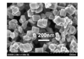
- decahedron ratio The ratio of decahedral titanium oxide particles (hereinafter referred to as “decahedron ratio”) is determined by observing titanium oxide particles (arbitrarily sampled powder product) with a scanning electron microscope in five or more fields of view. The ratio of decahedral titanium oxide particles contained in the titanium particles is calculated.
- FIG. 2 is a scanning electron micrograph obtained by enlarging the metal oxide particles (titanium oxide particles) of Example 1 by 100 k times. Moreover, it turned out that the specific surface area (BET) of the obtained particle
- the rutile ratio was 4%. This numerical value of the rutile ratio is a result obtained by estimating the ratio (%) of titanium oxide particles having a rutile crystal structure from the peak intensity obtained by X-ray diffraction measurement.
- the photocatalytic activity of the produced titanium oxide was evaluated using a gas chromatography method.
- 10 mg of titanium oxide powder was placed in a petri dish having an inner diameter of 27 mm, dispersed by adding water, and then dried at 110 ° C.
- this petri dish was placed in a 500 ml chamber, the interior was replaced with synthetic air, and then xenon light source with 500 ppm acetaldehyde equivalent and 5.8 ⁇ l water (corresponding to 50% relative humidity at 25 ° C.).
- the amount of carbon dioxide (CO 2 ) generated per hour was quantified by gas chromatography by irradiation with 0.2 mW / cm 2 of light. As a result, the amount of carbon dioxide (CO 2 ) generated as photocatalytic activity was 120 ppm / h.
- Example 2 to 4 The flow rate of the first gas G2, the concentration of titanium tetrachloride in the first combined gas, the residence time of the first combined gas in the first zone B, the residence time of the second combined gas in the second reaction zone A, the first combined gas temperature
- the second combined gas temperature and the Reynolds number of the second combined gas in the second reaction zone A were changed as shown in Tables 1 and 2, the metals of Examples 2 to 4 were used. Oxide particles were produced.
- Examples 5 to 7 Titanium tetrachloride supply amount, titanium tetrachloride concentration in the first combined gas, residence time of the first combined gas in the first zone B, residence time of the second combined gas in the second reaction zone A, first combined gas temperature, Except for changing the second combined gas temperature and the Reynolds number of the second combined gas in the second reaction zone A as shown in Tables 1 and 2, the metal oxidation of Examples 5 to 7 was performed in the same manner as in Example 1. Product particles were produced.
- Example 8 Preheating temperature of the first gas G2, residence time of the first joined gas in the first zone B, residence time of the second joined gas in the second reaction zone A, first joined gas temperature, second joined gas temperature, second reaction Example 8 metal oxide particles of Example 8 were produced in the same manner as in Example 1 except that the Reynolds number of the second combined gas in Zone A was changed as shown in Tables 1 and 2.
- Example 9 The preheating temperature of the first gas G2, the preheating temperature of the second gas G3, the residence time of the first combined gas in the first zone B, the residence time of the second combined gas in the second reaction zone A, the first combined gas temperature, the first 2 except that the combined gas temperature and the Reynolds number of the second combined gas in the second reaction zone A are changed as shown in Tables 1 and 2, and the metal oxide particles of Example 9 were used in the same manner as in Example 1. Manufactured.
- Example 10 Tables 1 and 2 show the preheating temperature of the second gas G3, the residence time of the second combined gas in the second reaction zone A, the second combined gas temperature, and the Reynolds number of the second combined gas in the second reaction zone A.
- the metal oxide particles of Example 10 were produced in the same manner as in Example 1 except that the above changes were made.
- Example 11 Except for changing the preheating temperature of the metal chloride-containing gas G1, the first combined gas temperature, the second combined gas temperature, and the Reynolds number of the second combined gas in the second reaction zone A as shown in Tables 1 and 2. In the same manner as in Example 1, metal oxide particles of Example 11 were produced.
- Example 12 The preheating temperature of the metal chloride-containing gas G1, the residence time of the first combined gas in the first zone B, the residence time of the second combined gas in the second reaction zone A, the first combined gas temperature, the second combined gas temperature, The metal oxide particles of Example 12 were produced in the same manner as in Example 1 except that the Reynolds number of the second combined gas in the two reaction zones A was changed as shown in Tables 1 and 2.
- Comparative Example 1 The manufacturing apparatus of Comparative Example 1 has the same configuration as the manufacturing apparatus 101 of Example 1. Comparison was made in the same manner as in Example 1 except that the type of the first gas G2, the first combined gas temperature, and the Reynolds number of the second combined gas in the second reaction zone A were changed as shown in Tables 1 and 2. The metal oxide particles of Example 1 were produced.
- Comparative Example 2 The manufacturing apparatus of Comparative Example 2 also has the same configuration as the manufacturing apparatus 101 of Example 1.
- Supply amount of titanium tetrachloride, type of first gas G2, concentration of titanium tetrachloride in the first combined gas, residence time of the first combined gas in the first zone B, residence time of the second combined gas in the second reaction zone A The first combined gas temperature, the second combined gas temperature, and the Reynolds number of the second combined gas in the second reaction zone A are compared in the same manner as in Example 1 except that they are changed as shown in Tables 1 and 2.
- the metal oxide particles of Example 2 were produced.
- Comparative Example 3 The manufacturing apparatus of Comparative Example 3 also has the same configuration as the manufacturing apparatus 101 of Example 1.
- Type of first gas G2, residence time of first combined gas in first zone B, residence time of second combined gas in second reaction zone A, first combined gas temperature, second combined gas temperature, second reaction zone Metal oxide particles of Comparative Example 3 were produced in the same manner as in Example 1 except that the Reynolds number of the second combined gas at A was changed as shown in Tables 1 and 2.
- Comparative Example 4 The manufacturing apparatus of Comparative Example 4 has the same configuration as the manufacturing apparatus 101 of Example 1.
- the metal oxide of Comparative Example 4 was the same as Example 1 except that the second combined gas temperature and the Reynolds number of the second combined gas in the second reaction zone A were changed as shown in Tables 1 and 2. Particles were produced.
- Comparative Example 5 For comparison of properties, commercially available titanium oxide particles for photocatalyst were purchased.
- the titanium oxide particles (Comparative Example 5) were particles synthesized by a flame method. As a result of observation using an electron microscope, the particle shape was indefinite and the primary particle size was 20 to 60 nm. Further, from the results of X-ray diffraction measurement, it was found that the particles were a mixture of anatase and rutile.
- Table 3 shows the yields of the powder products of Examples 1 to 12 and Comparative Examples 1 to 5, the decahedral ratio in the powder products, the photocatalytic activity, the specific surface area (measured BET, m 2 / g), The rutile ratio is summarized.
- Comparative Examples 1 to 3 in which oxygen is flowed to the first combustion-supporting gas, although titanium oxide deposits on the first and second hollow inner cylindrical quartz tubes are hardly formed at the initial stage of production, the production is continued. Over time, titanium oxide deposits gradually accumulated, and the flow path was blocked within a total production time of 5 to 20 hours, and the quartz glass was broken. For this reason, it turned out that production for a long time cannot be performed. Comparative Example 3 was a production method according to the description in Patent Document 3 (Japanese Patent Laid-Open No. 2011-184235), and the photocatalytic activity and the yield of the powder product were high.
- Example 1 the characteristics of the titanium oxide particles obtained were compared by changing the flow rate of the first gas G2 to change the residence time of the first combined gas in the first zone B.
- the length was increased from 47 milliseconds to 47 milliseconds (Example 3) and 75 milliseconds (Example 4) to 32 milliseconds in Example 1, the rutile ratio slightly increased from 4% to 6% to increase the photocatalytic activity. Decreased slightly. On the contrary, when it was shortened to 27 milliseconds (Example 2), the photocatalytic activity was slightly lowered although the rutile ratio was slightly lowered.
- Example 1 the characteristics of titanium oxide particles obtained by changing the titanium tetrachloride concentration (volume%) in the first combined gas by changing the flow rate of titanium tetrachloride were compared.
- Example 5 in which the concentration of titanium tetrachloride in the first combined gas was 0.6% compared to 3.8% in Example 1, the BET value increased and the photocatalytic activity slightly increased.
- Example 6 When the concentration of titanium tetrachloride in the first combined gas is increased to 5.9% (Example 6) and 13.6% (Example 7) with respect to 3.8% of Example 1,
- the BET value decreased from 14 m 2 / g to 9 m 2 / g and the rutile ratio increased from 4% to 8%.
- the titanium tetrachloride concentration in the first combined gas is preferably 0.1 to 20% by volume, more preferably 0.5 to 10% by volume, and 0.5 to 5% by volume. More preferably.
- the characteristics of titanium oxide particles obtained by changing the preheating temperature of the first gas G2 were compared.
- the rutile ratio was the same as in Example 1, and the photocatalytic activity was relatively high.
- the preheating temperature of the first gas G2 is preferably in the range of 800 ° C. or higher and 1050 ° C. or lower, and more preferably in the range of 850 ° C. or higher and 1050 ° C. or lower. preferable.
- Example 1 the characteristics of titanium oxide particles obtained by changing the preheating temperature of the second gas G3 were compared.
- Example 8 in which the preheating temperature of the first gas G2 is 900 ° C. and the preheating temperature of the second gas G3 is 1030 ° C., the preheating temperature of the first gas G2 is 900 ° C., and the preheating temperature of the second gas G3 is 950.
- Example 9 which was set to ° C., the photocatalytic activity was slightly reduced, although the rutile ratio was slightly decreased.
- the preheating temperature of the second gas G3 is preferably in the range of 900 ° C. or higher and 1100 ° C. or lower, and more preferably in the range of 950 ° C. or higher and 1050 ° C. or lower.
- the characteristics of titanium oxide particles obtained by changing the temperature of the metal chloride-containing gas G1 were compared.
- the preheating temperature of the metal chloride-containing gas G1 is preferably in the range of 600 ° C. or higher and 1000 ° C. or lower, more preferably in the range of 600 ° C. or higher and 950 ° C. or lower, and 800 ° C. or higher and 950 ° C. or lower. More preferably, it is in the range.
- Example 8 the temperature of the first combined gas was lowered by lowering the preheating temperature of the first gas G2 than in Example 1. Specifically, the temperature of the first combined gas in Example 1 was 979 ° C., whereas the temperature of the first combined gas was lowered to 895 ° C. in Example 8, but a relatively high photocatalytic activity was obtained. It was.
- Example 12 the temperature of the first combined gas was lowered by lowering the preheating temperature of the metal chloride-containing gas G1 than in Example 1. Specifically, the temperature of the first combined gas in Example 1 was 979 ° C., whereas the temperature of the first combined gas was lowered to 925 ° C. in Example 12, but a relatively high photocatalytic activity was obtained. It was.
- Example 11 the temperature of the first combined gas was raised by raising the preheating temperature of the metal chloride-containing gas G1 than in Example 1.
- the rutile ratio was 4% when the temperature of the first combined gas was 979 ° C.
- the rutile ratio was increased in Example 11 when the temperature of the first combined gas was increased to 1003 ° C.
- the photocatalytic activity decreased to 5%.
- the temperature of the first combined gas is preferably in the temperature range of 800 ° C. or higher and 1050 ° C. or lower, more preferably in the temperature range of 850 ° C. or higher and 1000 ° C. or lower, and still more preferably 900 ° C. or higher and 1000 ° C. or lower. .
- Example 1 characteristics of titanium oxide particles obtained by changing the temperature of the second combined gas were compared.
- the temperature of the second combined gas was set to 1020 ° C., whereas in Example 9, the temperature of the second combined gas was lowered to 939 ° C., but the photocatalytic activity was only slightly reduced.
- the rutile ratio was 4% when the temperature of the second combined gas was 1020 ° C., whereas in Example 10, the temperature of the second combined gas was increased to 1076 ° C.
- the rutile ratio increased to 12%, and the photocatalytic activity decreased significantly.
- the temperature of the second combined gas is preferably in the temperature range of 800 ° C. or higher and 1100 ° C. or lower, more preferably in the temperature range of 800 ° C. or higher and 1050 ° C. or lower, and still more preferably 850 ° C. or higher and 1050 ° C. or lower. .
- the present invention relates to a method for producing metal oxide particles and an apparatus for producing the same, and more particularly to a method for producing titanium oxide particles capable of producing titanium oxide having high photocatalytic activity for a long time. Therefore, it can be used in the photocatalyst industry.
- Hollow outer cylinder opening part, DESCRIPTION OF SYMBOLS 101 Manufacturing apparatus of metal oxide particle, A ... 2nd reaction zone, B ... 1st zone, G1 ... Metal chloride containing gas, G2 ... 1st gas, G3 ... 2nd gas, X ... Preheating area
Landscapes
- Chemical & Material Sciences (AREA)
- Organic Chemistry (AREA)
- Inorganic Chemistry (AREA)
- Life Sciences & Earth Sciences (AREA)
- Environmental & Geological Engineering (AREA)
- General Life Sciences & Earth Sciences (AREA)
- Geology (AREA)
- Inorganic Compounds Of Heavy Metals (AREA)
- Catalysts (AREA)
Abstract
本発明の金属酸化物粒子の製造方法は、予熱された金属塩化物含有ガスに、金属塩化物を含まない予熱された第1ガスを第1合流地点で合流させて第1合流ガスとし、第1合流ガスに、金属塩化物を含まない予熱された第2ガスを、第1合流地点よりも下流側に離れた第2合流地点で合流させて第2合流ガスとする工程を含み、金属塩化物含有ガス及び第1ガスの両方とも酸素、水蒸気を含有せず、第2ガスは少なくとも酸素を含有しており、第1ガスの予熱温度を、金属塩化物含有ガスの予熱温度以上の温度として合流させて、予熱された金属塩化物含有ガスを加熱し、第2ガスの予熱温度を、第1合流ガスの温度以上の温度として第1合流ガスと合流させて、第2合流地点から下流側において第1合流ガスを加熱することを特徴とする。
Description
本発明は、金属酸化物粒子の製造方法に関するものであり、特に、原料ガス流路を閉塞させずに、長時間金属酸化物粒子を製造する金属酸化物粒子の製造方法に関する。
本発明は、2015年1月14日に、日本に出願された特願2015-005149号に基づき優先権を主張し、その内容をここに援用する。
本発明は、2015年1月14日に、日本に出願された特願2015-005149号に基づき優先権を主張し、その内容をここに援用する。
近年、光触媒の分野で酸化チタン粒子が注目されている。例えば、特許文献1、2及び非特許文献1~3には、十面体の箱型形状を有し、主としてアナターゼ型結晶からなる酸化チタン粒子(以下、「十面体酸化チタン粒子」と称する。)が開示されている。
特許文献1、2及び非特許文献1、3には、十面体酸化チタン粒子は単位質量当たりの表面積が大きく、結晶性が高い上に内部欠陥も少ないので、光触媒として高い活性を有することが記載されている。また、非特許文献2には、十面体酸化チタン粒子は反応性の高い(001)面の比率が高く、光触媒として有望であることが記載されている。
特許文献1、2及び非特許文献1、3には、十面体酸化チタン粒子は単位質量当たりの表面積が大きく、結晶性が高い上に内部欠陥も少ないので、光触媒として高い活性を有することが記載されている。また、非特許文献2には、十面体酸化チタン粒子は反応性の高い(001)面の比率が高く、光触媒として有望であることが記載されている。
十面体酸化チタン粒子の製造方法としては、例えば、非特許文献2に記載のフッ酸を用いた水熱反応を利用する方法がある。しかし、フッ酸は、強い酸性を有し、取扱いが困難な物質であることから、これを用いる非特許文献2の製造方法は、工業的な用途には適さない。
特許文献1、2及び非特許文献1、3に記載されている十面体酸化チタン粒子の製造方法は、反応管内に四塩化チタン(TiCl4)蒸気と酸素(O2)ガスとを導入した後、これらのガスを反応管の外部から加熱して、下記反応式(1)に示す反応により、酸化チタン粒子TiO2を製造する方法である。
TiCl4+O2→TiO2+2Cl2…(1)
特許文献1、2及び非特許文献1、3に記載されている十面体酸化チタン粒子の製造方法は、反応管内に四塩化チタン(TiCl4)蒸気と酸素(O2)ガスとを導入した後、これらのガスを反応管の外部から加熱して、下記反応式(1)に示す反応により、酸化チタン粒子TiO2を製造する方法である。
TiCl4+O2→TiO2+2Cl2…(1)
上記製造方法を用いることにより、反応管の下流側で、酸化チタン粒子を含む粉末生成物を得ることができる。この粉状生成物には、十面体酸化チタン粒子が多く含まれる。
特許文献1、2及び非特許文献1、3に記載されている上記製造方法は、四塩化チタンの熱酸化反応が進行する温度まで原料ガスを急昇温する際に、原料となる四塩化チタンと酸素ガスを反応管の外部から加熱する方式をとっている。そのため、四塩化チタンと酸化性ガスを含む原料ガスの流量が多い場合には、反応管外部の熱源から反応管内の原料ガスに対して、原料ガス中の四塩化チタンが熱酸化反応によって全て消費されるのに必要なだけの熱伝導が確保されず、反応完結せずに、反応ゾーンよりも下流側において未反応四塩化チタンが残存する結果、得られる粉末生成物の収率が低下する問題が生じる。
特許文献1、2及び非特許文献1、3に記載されている上記製造方法は、四塩化チタンの熱酸化反応が進行する温度まで原料ガスを急昇温する際に、原料となる四塩化チタンと酸素ガスを反応管の外部から加熱する方式をとっている。そのため、四塩化チタンと酸化性ガスを含む原料ガスの流量が多い場合には、反応管外部の熱源から反応管内の原料ガスに対して、原料ガス中の四塩化チタンが熱酸化反応によって全て消費されるのに必要なだけの熱伝導が確保されず、反応完結せずに、反応ゾーンよりも下流側において未反応四塩化チタンが残存する結果、得られる粉末生成物の収率が低下する問題が生じる。
一方、特許文献3に記載されている製造方法は、原料となる四塩化チタンを、予熱された第1ガス、第2ガスと2段階で合流させて加熱することで、原料ガスの流量が多い場合であっても、光触媒活性の高い酸化チタン粒子を、高い収率で製造することができる。
しかし、特許文献3に記載されている製造方法では、予熱された四塩化チタン含有ガス及び予熱された第1ガスの少なくとも一方は酸素を含有しているために、四塩化チタン含有ガスを導入する石英ガラス製第1中空内筒の先端、内表面、外表面、第1ガスを導入する石英ガラス製第2中空内筒の先端、内表面に酸化チタンの固着物、膜状生成物、付着物が初期にはほとんど付かないものの、酸化チタン粒子を長時間生産しようとすると、徐々に蓄積されていき、最終的には原料ガス流路が閉塞して第1中空内筒や第2中空内筒が破損する問題が生じる。
上記、第1中空内筒の先端、内表面、外表面、第1ガスを導入する石英ガラス製第2中空内筒の先端、内表面に蓄積する、固着物、膜状生成物、付着物が原料ガス流路を閉塞させる前に、生産を中断してこれらを冶具等で掻き取ろうとしても、ガラスに強固に固着しているために、ガラスを破損することがしばしば生じる。
しかし、特許文献3に記載されている製造方法では、予熱された四塩化チタン含有ガス及び予熱された第1ガスの少なくとも一方は酸素を含有しているために、四塩化チタン含有ガスを導入する石英ガラス製第1中空内筒の先端、内表面、外表面、第1ガスを導入する石英ガラス製第2中空内筒の先端、内表面に酸化チタンの固着物、膜状生成物、付着物が初期にはほとんど付かないものの、酸化チタン粒子を長時間生産しようとすると、徐々に蓄積されていき、最終的には原料ガス流路が閉塞して第1中空内筒や第2中空内筒が破損する問題が生じる。
上記、第1中空内筒の先端、内表面、外表面、第1ガスを導入する石英ガラス製第2中空内筒の先端、内表面に蓄積する、固着物、膜状生成物、付着物が原料ガス流路を閉塞させる前に、生産を中断してこれらを冶具等で掻き取ろうとしても、ガラスに強固に固着しているために、ガラスを破損することがしばしば生じる。
草野大輔、寺田佳弘、阿部竜、大谷文章、第98回触媒討論会(平成18年9月)、討論会A予稿集、234頁
Hua Gui Yang et al.,Nature,Vol.453,p.638~p.641
Amano F.et al.,Chem.Mater.,21,2601~2603(2009)
本発明は、上記事情を鑑みてなされたもので、光触媒活性の高い金属酸化物粒子を、長時間製造する金属酸化物粒子の製造方法を提供することを目的とする。
反応管内で、予熱された金属塩化物を含む金属塩化物含有ガスに、この金属塩化物含有ガスの予熱温度以上の温度で予熱された第1ガスを合流させて金属塩化物含有ガスを加熱して、加熱されて金属塩化物含有ガスの予熱温度以上の温度になった合流ガスに、さらにこの合流ガスの温度以上の温度で予熱された第2ガスを合流させることによってさらにガスを加熱する製造方法において、前記金属塩化物含有ガス及び前記第1ガスの両方とも酸素、水蒸気を含有させないことによって光触媒活性の高い金属酸化物粒子を、長時間製造できることを見出して、以下の発明を完成した。
上記の目的を達成するために、本発明は以下の構成を採用した。すなわち、
(1)反応管内で、予熱された金属塩化物含有ガスに、前記金属塩化物を含まない予熱された第1ガスを第1合流地点で合流させて第1合流ガスとし、該第1合流ガスに、前記金属塩化物を含まない予熱された第2ガスを、前記第1合流地点よりも下流側に離れた第2合流地点で合流させて第2合流ガスとする工程を含む金属酸化物粒子の製造方法であって、前記金属塩化物含有ガス及び前記第1ガスの両方とも酸素、水蒸気を含有せず、前記第2ガスは少なくとも酸素を含有しており、前記第1ガスの予熱温度を、前記金属塩化物含有ガスの予熱温度以上の温度として前記第1ガスを前記第1合流地点で合流させることで、前記第1合流地点から前記第2合流地点までの間(第1ゾーンと呼ぶ)において、予熱された前記金属塩化物含有ガスをさらに加熱し、前記第2ガスの予熱温度を、前記第1合流ガスの温度以上の温度として前記第1合流ガスと合流させることで、前記第2合流地点から下流側において、前記第1合流ガスをさらに加熱することを特徴とする金属酸化物粒子の製造方法。
(2)前記金属塩化物が四塩化チタンであり、前記金属酸化物粒子が酸化チタン粒子であることを特徴とする請求項1に記載の金属酸化物粒子の製造方法。
(3)前記酸化チタン粒子が十面体酸化チタン粒子であることを特徴とする前項(2)に記載の金属酸化物粒子の製造方法。
(4)前記金属塩化物含有ガスの予熱温度が600℃以上1000℃以下であることを特徴とする前項(1)~(3)のいずれか1項に記載の金属酸化物粒子の製造方法。
(5)前記第1合流ガスの温度が800℃以上1050℃以下であることを特徴とする前項(1)~(4)のいずれか1項に記載の金属酸化物粒子の製造方法。
(6)前記第2合流ガスの温度が800℃以上1100℃以下であることを特徴とする前項(1)~(5)のいずれか1項に記載の金属酸化物粒子の製造方法。
(7)前記第1ガスの予熱温度が800℃以上1050℃以下であることを特徴とする前項(1)~(6)のいずれか1項に記載の金属酸化物粒子の製造方法。
(8)前記第2ガスの予熱温度が900℃以上1100℃以下であることを特徴とする前項(1)~(7)のいずれか1項に記載の金属酸化物粒子の製造方法。
(9)前記金属塩化物含有ガスが、窒素ガスを含むことを特徴とする前項(1)~(8)のいずれか1項に記載の金属酸化物粒子の製造方法。
(10)前記第1ガスが、窒素ガス及びアルゴンからなる群から選ばれた1種以上のガスを含むことを特徴とする前項(1)~(9)のいずれか1項に記載の金属酸化物粒子の製造方法。
(11)前記第2ガスが、酸素ガスとともに、窒素ガス、アルゴン及び水蒸気からなる群から選ばれた1種以上のガスを含むことを特徴とする前項(1)~(10)のいずれか1項に記載の金属酸化物粒子の製造方法。
(12)前記第1合流ガスに含まれる前記四塩化チタンの濃度を0.1~20体積%とすることを特徴とする前項(2)~(11)のいずれか1項に記載の金属酸化物粒子の製造方法。
(13)前記第1合流ガスが、前記第1ゾーンにおいて滞留する時間を2~100ミリ秒とすることを特徴とする前項(1)~(12)のいずれか1項に記載の金属酸化物粒子の製造方法。
(14)前記第2合流ガスのレイノルズ数を10~10000とすることを特徴とする前項(1)~(13)のいずれか1項に記載の金属酸化物粒子の製造方法。
(1)反応管内で、予熱された金属塩化物含有ガスに、前記金属塩化物を含まない予熱された第1ガスを第1合流地点で合流させて第1合流ガスとし、該第1合流ガスに、前記金属塩化物を含まない予熱された第2ガスを、前記第1合流地点よりも下流側に離れた第2合流地点で合流させて第2合流ガスとする工程を含む金属酸化物粒子の製造方法であって、前記金属塩化物含有ガス及び前記第1ガスの両方とも酸素、水蒸気を含有せず、前記第2ガスは少なくとも酸素を含有しており、前記第1ガスの予熱温度を、前記金属塩化物含有ガスの予熱温度以上の温度として前記第1ガスを前記第1合流地点で合流させることで、前記第1合流地点から前記第2合流地点までの間(第1ゾーンと呼ぶ)において、予熱された前記金属塩化物含有ガスをさらに加熱し、前記第2ガスの予熱温度を、前記第1合流ガスの温度以上の温度として前記第1合流ガスと合流させることで、前記第2合流地点から下流側において、前記第1合流ガスをさらに加熱することを特徴とする金属酸化物粒子の製造方法。
(2)前記金属塩化物が四塩化チタンであり、前記金属酸化物粒子が酸化チタン粒子であることを特徴とする請求項1に記載の金属酸化物粒子の製造方法。
(3)前記酸化チタン粒子が十面体酸化チタン粒子であることを特徴とする前項(2)に記載の金属酸化物粒子の製造方法。
(4)前記金属塩化物含有ガスの予熱温度が600℃以上1000℃以下であることを特徴とする前項(1)~(3)のいずれか1項に記載の金属酸化物粒子の製造方法。
(5)前記第1合流ガスの温度が800℃以上1050℃以下であることを特徴とする前項(1)~(4)のいずれか1項に記載の金属酸化物粒子の製造方法。
(6)前記第2合流ガスの温度が800℃以上1100℃以下であることを特徴とする前項(1)~(5)のいずれか1項に記載の金属酸化物粒子の製造方法。
(7)前記第1ガスの予熱温度が800℃以上1050℃以下であることを特徴とする前項(1)~(6)のいずれか1項に記載の金属酸化物粒子の製造方法。
(8)前記第2ガスの予熱温度が900℃以上1100℃以下であることを特徴とする前項(1)~(7)のいずれか1項に記載の金属酸化物粒子の製造方法。
(9)前記金属塩化物含有ガスが、窒素ガスを含むことを特徴とする前項(1)~(8)のいずれか1項に記載の金属酸化物粒子の製造方法。
(10)前記第1ガスが、窒素ガス及びアルゴンからなる群から選ばれた1種以上のガスを含むことを特徴とする前項(1)~(9)のいずれか1項に記載の金属酸化物粒子の製造方法。
(11)前記第2ガスが、酸素ガスとともに、窒素ガス、アルゴン及び水蒸気からなる群から選ばれた1種以上のガスを含むことを特徴とする前項(1)~(10)のいずれか1項に記載の金属酸化物粒子の製造方法。
(12)前記第1合流ガスに含まれる前記四塩化チタンの濃度を0.1~20体積%とすることを特徴とする前項(2)~(11)のいずれか1項に記載の金属酸化物粒子の製造方法。
(13)前記第1合流ガスが、前記第1ゾーンにおいて滞留する時間を2~100ミリ秒とすることを特徴とする前項(1)~(12)のいずれか1項に記載の金属酸化物粒子の製造方法。
(14)前記第2合流ガスのレイノルズ数を10~10000とすることを特徴とする前項(1)~(13)のいずれか1項に記載の金属酸化物粒子の製造方法。
上記の構成によれば、光触媒活性の高い金属酸化物粒子を、長時間製造する金属酸化物粒子の製造方法を提供することができる。
本発明の金属酸化物粒子の製造方法は、反応管内で、予熱された金属塩化物含有ガスに、前記金属塩化物を含まない予熱された第1ガスを第1合流地点で合流して第1合流ガスとし、該第1合流ガスに、前記金属塩化物を含まない予熱された第2ガスを前記第1合流地点よりも下流側に離れた第2合流地点で合流して第2合流ガスとする工程を含む金属酸化物粒子の製造方法であって、前記金属塩化物含有ガス及び前記第1ガスの両方とも酸素、水蒸気を含有せず、前記第1ガスの予熱温度を、前記金属塩化物含有ガスの予熱温度以上の温度として前記第1ガスを前記第1合流地点で合流させることで、前記第1合流地点から前記第2合流地点までの間において予熱された前記金属塩化物含有ガスをさらに加熱し、前記第2ガスの予熱温度を、前記第1合流ガスの温度以上の温度として前記第1合流ガスと合流させることで、前記第2合流地点から下流側において前記第1合流ガスをさらに加熱することによって、光触媒活性の高い金属酸化物粒子を、長時間製造することができる。
本発明の金属酸化物粒子の製造方法では、前記金属塩化物として四塩化チタンを用い、製造される前記金属酸化物粒子が酸化チタン粒子であることが好ましく、この場合にも、前記金属塩化物含有ガス及び前記第1ガスの両方とも酸素、水蒸気を含有させずに、前記第1ガスの予熱温度を、前記金属塩化物含有ガスの予熱温度以上の温度として前記第1ガスを前記第1合流地点で合流させることで、前記第1合流地点から前記第2合流地点までの間において予熱された前記金属塩化物含有ガスをさらに加熱し、前記第2ガスの予熱温度を、前記第1ガス合流温度以上の温度として前記第1合流ガスと合流させることで、前記第2合流地点から下流側において前記第1合流ガスをさらに加熱することによって、光触媒活性の高い酸化チタン粒子を、長時間製造することができる。
本発明の金属酸化物粒子の製造装置は、反応管と、金属塩化物含有ガス、第1のガス及び第2のガスのそれぞれを予熱する予熱部とを具備し、前記反応管は、中空外筒と、該中空外筒の上流側から該中空外筒の途中まで挿入されてなる第2中空内筒と、該第2中空内筒の上流側から該第2中空内筒の途中まで挿入されてなる第1中空内筒とを備え、前記第2中空内筒はその上流側に予熱された前記第1のガスを導入する第1導管を備え、前記中空外筒はその上流側に予熱された前記第2のガスを導入する第2導管を備え、予熱された前記金属塩化物含有ガスは第1中空内筒の上流側から導入され、導入された前記金属塩化物含有ガスは前記第1中空内筒の下流端で予熱された前記第1のガスと合流し、該合流したガスは前記第2中空内筒の下流端で予熱された前記第2のガスとさらに合流することができることによって、光触媒活性の高い金属酸化物粒子を、長時間製造することができる。
以下、本発明を適用した一実施形態である金属酸化物粒子の製造方法及び製造装置について、図面を用いて詳細に説明する。なお、以下の説明で用いる図面は、特徴をわかりやすくするために簡潔に模式的に示しており、各構成要素の寸法比率などは実際のものと同じではない。
<金属酸化物粒子の製造装置>
図1は、本発明の実施形態である金属酸化物粒子の製造方法において用いる製造装置の一例を示す模式図である。
図1に示すように、本発明の実施形態である金属酸化物粒子の製造方法において用いる製造装置101は、中空外筒1と、中空外筒1の上流側(上流部)1aから中空外筒1の途中まで挿入されてなる第2中空内筒5と、第2中空内筒5の上流側5aから第2中空内筒5の途中まで挿入されてなる第1中空内筒4と、からなる反応管11を具備するとともに、反応管11の外部に反応管11の一部を保温するように断熱材2が配置されて概略構成されている。
図1は、本発明の実施形態である金属酸化物粒子の製造方法において用いる製造装置の一例を示す模式図である。
図1に示すように、本発明の実施形態である金属酸化物粒子の製造方法において用いる製造装置101は、中空外筒1と、中空外筒1の上流側(上流部)1aから中空外筒1の途中まで挿入されてなる第2中空内筒5と、第2中空内筒5の上流側5aから第2中空内筒5の途中まで挿入されてなる第1中空内筒4と、からなる反応管11を具備するとともに、反応管11の外部に反応管11の一部を保温するように断熱材2が配置されて概略構成されている。
<反応管>
図1に示すように、反応管11は、中空外筒1と、第1中空内筒4と、第2中空内筒5を有して構成されている。反応管11は、例えば、石英などからなる円筒管で構成されている。
第2中空内筒5は、中空外筒1の上流側1aから途中まで挿入されてなり、その下流端5bは、中空外筒1の長手方向で中心付近にあるように配置されている。第1中空内筒4は、第2中空内筒5の上流側5aから途中まで挿入されてなり、その下流端4bは、第2中空内筒5の長手方向で中心付近にあるように配置されている。
図1に示すように、反応管11は、中空外筒1と、第1中空内筒4と、第2中空内筒5を有して構成されている。反応管11は、例えば、石英などからなる円筒管で構成されている。
第2中空内筒5は、中空外筒1の上流側1aから途中まで挿入されてなり、その下流端5bは、中空外筒1の長手方向で中心付近にあるように配置されている。第1中空内筒4は、第2中空内筒5の上流側5aから途中まで挿入されてなり、その下流端4bは、第2中空内筒5の長手方向で中心付近にあるように配置されている。
<金属塩化物含有ガス>
予熱領域(予熱部)Xで予熱された金属塩化物含有ガスG1は、第1中空内筒4の上流側4aの第1中空内筒開口部24に流し込まれる。
図では省略しているが、予熱領域Xの上流側には、四塩化チタン(TiCl4)などの金属塩化物を蒸発させるための気化器が設置され、この気化器の上流側には、液体の金属塩化物を気化器に導入するための導入管と、窒素を含むガスを供給するための導入管とが、それぞれバルブを介して気化器と接続されている。気化器は、たとえば温度を165℃として、液体の金属塩化物を気化して金属塩化物蒸気とする機能を有している。これにより、金属塩化物蒸気と窒素を含む混合ガスからなる金属塩化物含有ガスG1を、予熱領域Xに供給できる構成とされている。
予熱領域(予熱部)Xで予熱された金属塩化物含有ガスG1は、第1中空内筒4の上流側4aの第1中空内筒開口部24に流し込まれる。
図では省略しているが、予熱領域Xの上流側には、四塩化チタン(TiCl4)などの金属塩化物を蒸発させるための気化器が設置され、この気化器の上流側には、液体の金属塩化物を気化器に導入するための導入管と、窒素を含むガスを供給するための導入管とが、それぞれバルブを介して気化器と接続されている。気化器は、たとえば温度を165℃として、液体の金属塩化物を気化して金属塩化物蒸気とする機能を有している。これにより、金属塩化物蒸気と窒素を含む混合ガスからなる金属塩化物含有ガスG1を、予熱領域Xに供給できる構成とされている。
金属塩化物含有ガスG1は、四塩化チタン等の蒸気を含むガスである。具体的には、この金属塩化物含有ガスG1は、四塩化チタン等の蒸気と窒素との混合ガス、四塩化チタン等の蒸気と窒素を含む不活性ガスとの混合ガスを用いることができる。
<第1ガス>
第1中空内筒4の下流側4bと第2中空内筒5の上流側5aとの間のリング状開口部25には、予熱領域(予熱部)Yで予熱された第1ガスG2が流し込まれる。
第1中空内筒4の下流側4bと第2中空内筒5の上流側5aとの間のリング状開口部25には、予熱領域(予熱部)Yで予熱された第1ガスG2が流し込まれる。
第1ガスG2は、四塩化チタンなどの金属塩化物や、酸素、水蒸気を含まないガスである。具体的には、この第1ガスG2は、窒素、アルゴンなどの不活性ガスなどであり、これらを単独で用いても、混合して用いてもよい。従って、窒素のみからなるガス、アルゴンのみからなるガス、窒素とアルゴンなどの不活性ガスとの混合ガス、などを用いることができる。
<第2ガス>
第2中空内筒5の下流側5bと中空外筒1の上流側1aとの間のリング状開口部26には、予熱領域(予熱部)Zで予熱された第2ガスG3が流し込まれる。
第2中空内筒5の下流側5bと中空外筒1の上流側1aとの間のリング状開口部26には、予熱領域(予熱部)Zで予熱された第2ガスG3が流し込まれる。
第2ガスG3は、四塩化チタンなどの金属塩化物を含まないガスである。具体的には、第2ガスG3は、少なくとも酸素(O2)を含有している。また、第2ガスG3は、酸素とともに、窒素やアルゴンなどの不活性ガス、水蒸気及びオゾン(O3)、あるいはこれらの混合物を含有していてもよい。従って、第2ガスG3は、酸素のみの状態、窒素やアルゴンなどの不活性ガスと酸素との混合ガスの状態、水蒸気と酸素との混合ガスの状態、不活性ガスと水蒸気と酸素との混合ガスの状態などをとり得る。なお、不活性ガスと酸素との混合ガスとして、空気を用いてもよい。
第1中空内筒4と第2中空内筒5とは、同軸構造とすることが好ましい。これにより、金属塩化物含有ガスG1を中心軸側に集めることができ、第2中空内筒5の内壁面への四塩化チタン蒸気の拡散を抑制して、第2中空内筒5の内壁面に固着する膜状生成物(副生物)の発生を抑制することができる。
また、第2中空内筒5と中空外筒1とも、同軸構造とすることが好ましい。これにより、中空外筒1の内壁面への四塩化チタン蒸気の拡散を抑制して、第1中空外筒1の内壁面に固着する膜状生成物(副生物)の発生を抑制することができる。
<断熱材>
図1に示すように、反応管11の外部には、反応管内のガスの保温用に断熱材2が配置されている。断熱剤としては通常のセラミックファイバを用いる。
図1に示すように、反応管11の外部には、反応管内のガスの保温用に断熱材2が配置されている。断熱剤としては通常のセラミックファイバを用いる。
<第1合流地点>
金属塩化物含有ガスG1と第1ガスG2は第1中空内筒4の下流端4bで合流する。この両者の合流地点を第1合流地点という。
金属塩化物含有ガスG1と第1ガスG2は第1中空内筒4の下流端4bで合流する。この両者の合流地点を第1合流地点という。
<第1合流ガス>
第1合流地点で合流したガスを第1合流ガスという。
第1合流地点で合流したガスを第1合流ガスという。
<第2合流地点>
第1合流ガスと第2ガスG3は第2中空内筒5の下流端5bで合流する。この両者の合流地点を第2合流地点という。
第1合流ガスと第2ガスG3は第2中空内筒5の下流端5bで合流する。この両者の合流地点を第2合流地点という。
<第2合流ガス>
第2合流地点で合流したガスを第2合流ガスという。
第2合流地点で合流したガスを第2合流ガスという。
<第1ゾーン>
第1合流地点(第1中空内筒4の下流端4b)から第2合流地点(第2中空内筒5の下流端5b)までの間の、第1合流ガスが通過する領域を第1ゾーンという。
第1合流地点(第1中空内筒4の下流端4b)から第2合流地点(第2中空内筒5の下流端5b)までの間の、第1合流ガスが通過する領域を第1ゾーンという。
<第2反応ゾーン>
第2合流地点(第2中空内筒5の下流端5b)から断熱材2の下流端までの間の、第2合流ガスが通過する領域を第2反応ゾーンという。第2反応ゾーンにおいて、第2合流ガス中の四塩化チタン蒸気が酸化反応により消費される。
第2合流地点(第2中空内筒5の下流端5b)から断熱材2の下流端までの間の、第2合流ガスが通過する領域を第2反応ゾーンという。第2反応ゾーンにおいて、第2合流ガス中の四塩化チタン蒸気が酸化反応により消費される。
<予熱領域>
本発明の実施形態に係る金属酸化物粒子の製造装置101には、3つの予熱領域X、Y、Zが設けられている。
本発明の実施形態に係る金属酸化物粒子の製造装置101には、3つの予熱領域X、Y、Zが設けられている。
予熱領域X、Y、Zは、各々のガス流路の外部に電気ヒーター(図示略)などが配置されて構成される。予熱領域X、Y、Zにおいて、金属塩化物含有ガスG1、第1ガスG2、第2ガスG3をそれぞれ所定の予熱温度とする。
予熱領域Xの予熱温度(金属塩化物含有ガスG1の予熱温度)は、600℃以上1000℃以下の温度範囲とすることが好ましく、650℃以上950℃以下の温度範囲とすることがより好ましく、さらに好ましくは、800℃以上950℃以下の温度範囲とすることが好ましい。
予熱領域Xの予熱温度の範囲を600℃未満の範囲とすることにより、最終的に得られる粉末生成物の光触媒活性が低下する。また、予熱領域Xの予熱温度の範囲を1000℃以上の範囲とすることによっても、ルチル比率が高まり、十面体比率が下がる結果、最終的に得られる粉末生成物の光触媒活性が低下する。
予熱領域Xの予熱温度の範囲を600℃以上1000℃以下とすることにより、最終的に得られる粉末生成物中の十面体酸化チタン粒子の比率が高まり、その結果、高い光触媒活性を有する十面体酸化チタン粒子が得られる。
予熱領域Xの予熱温度の範囲を600℃未満の範囲とすることにより、最終的に得られる粉末生成物の光触媒活性が低下する。また、予熱領域Xの予熱温度の範囲を1000℃以上の範囲とすることによっても、ルチル比率が高まり、十面体比率が下がる結果、最終的に得られる粉末生成物の光触媒活性が低下する。
予熱領域Xの予熱温度の範囲を600℃以上1000℃以下とすることにより、最終的に得られる粉末生成物中の十面体酸化チタン粒子の比率が高まり、その結果、高い光触媒活性を有する十面体酸化チタン粒子が得られる。
予熱領域Yの予熱温度(第1ガスG2の予熱温度)は、予熱領域Xの予熱温度(金属塩化物含有ガスG1の予熱温度)以上の温度として、800℃以上1050℃以下の範囲とすることが好ましく、850℃以上1050℃以下の温度範囲とすることがより好ましい。
第1ガスG2の予熱温度を金属塩化物含有ガスG1の予熱温度以上の温度として合流させ、第1ゾーンにおいて、予熱領域Xで予熱された金属塩化物含有ガスG1をさらに加熱することによって、最終的に得られる粉末生成物中の十面体酸化チタン粒子の比率が高く、光触媒活性が高まる。逆に、第1ガスG2の予熱温度を金属塩化物含有ガスG1の予熱温度より低い温度とすると、最終的に得られる粉末生成物中の十面体酸化チタン粒子の比率が低く、光触媒活性が低下する。
予熱領域Yの予熱温度が800℃未満の温度範囲だと、得られる粉末生成物の十面体酸化チタン粒子の比率が低く、光触媒活性が低い。予熱領域Yの予熱温度が1050℃より高い温度範囲だと、得られる粉末生成物のルチル比率が高くなり、十面体酸化チタン粒子の比率が低く、光触媒活性が低下する。第1ガスG2の予熱温度を金属塩化物含有ガスG1の予熱温度以上として、800℃以上1050℃以下の温度範囲とすることにより、最終的に得られる粉末生成物中のルチル比率が低くなり、十面体酸化チタン粒子の比率が高まり、その結果、高い光触媒活性を有する十面体酸化チタン粒子が得られる。
予熱領域Zの予熱温度(第2ガスG3の予熱温度)は、予熱領域Yの予熱温度(第1ガスG2の予熱温度)以上の温度として、900℃以上1100℃以下の温度範囲とすることが好ましく、950℃以上1050℃以下の温度範囲とすることがさらに好ましい。第2ガスG3の予熱温度を第1合流ガス温度以上の温度として、第2合流地点において両者を合流させ、第2反応ゾーンにおいて、第1合流ガスをさらに加熱することによって、十面体比率が高く、高い光触媒活性の粒子を得ることができる。
予熱領域Zの予熱温度が900℃より低い温度範囲だと、第2合流ガスの温度、すなわち、第2反応ゾーンの温度が低くなり、第2反応ゾーンで反応完結せずに、得られる粉末生成物の収率が低下する場合が生じる。予熱領域Zの予熱温度が1100℃より高い温度範囲だと、最終的に得られる粉末生成物中のルチル比率が高くなり、十面体酸化チタン粒子の比率が低く、その結果、光触媒活性が低下する。
<第1合流ガス温度>
反応管11において、第1合流地点(第1中空内筒4の下流端4b)から第2合流地点(第2中空内筒5の下流端5b)までの間には、第1ゾーンBが設けられている。第1ゾーンBは、予熱された金属塩化物含有ガスG1と予熱された第1ガスG2が合流して第1合流ガスが形成され、第2ガスG3が合流されるまで第1合流ガスが流れる領域である。
第1合流ガス温度は、800℃以上1050℃以下の温度範囲とすることが好ましく、850℃以上1000℃以下とすることがより好ましく、さらに好ましくは900℃以上1000℃以下とすることが好ましい。第1合流ガス温度を800℃以上1050℃以下の温度範囲とすることにより、最終的に得られる粉末生成物中の十面体酸化チタン粒子の比率が高まり、高い光触媒活性が得られる。
反応管11において、第1合流地点(第1中空内筒4の下流端4b)から第2合流地点(第2中空内筒5の下流端5b)までの間には、第1ゾーンBが設けられている。第1ゾーンBは、予熱された金属塩化物含有ガスG1と予熱された第1ガスG2が合流して第1合流ガスが形成され、第2ガスG3が合流されるまで第1合流ガスが流れる領域である。
第1合流ガス温度は、800℃以上1050℃以下の温度範囲とすることが好ましく、850℃以上1000℃以下とすることがより好ましく、さらに好ましくは900℃以上1000℃以下とすることが好ましい。第1合流ガス温度を800℃以上1050℃以下の温度範囲とすることにより、最終的に得られる粉末生成物中の十面体酸化チタン粒子の比率が高まり、高い光触媒活性が得られる。
第1合流ガス温度が800℃未満の場合には、最終的に得られる粉末生成物中の十面体酸化チタン粒子の比率が低下し、光触媒活性が低下する。第2合流ガス温度が1050℃より高い温度の場合には、最終的に得られる粉末生成物のルチル比率が高くなり、光触媒活性が低下する。
第1合流ガス温度T1[℃]の算出方法について、金属塩化物含有ガスG1として四塩化チタンと窒素、第1ガスG2として窒素、第2ガスG3として酸素を用いた場合を例として説明する。
T1=Q1/C1、
Q1=QR,T+QR,N+Q1G,N、
QR,T=GR、T×CpT×TR、
QR,N=GR,N×CpN×TR、
Q1G,N=G1G,N×CpN×T1G、
C1=GR、T×CpT+GR、N×CpN+G1G,N×CpN、という式で計算する。
ここで、Q1は金属塩化物含有ガスG1と第1ガスG2による第1合流地点への持ち込み熱量の合計量[kcal]、C1は第1合流ガスの熱容量[kcal/℃]、QR,Tは金属塩化物含有ガスG1中の四塩化チタンによる第1合流地点への持ち込み熱量[kcal]、QR,Nは金属塩化物含有ガスG1中の窒素による第1合流地点への持ち込み熱量[kcal]、Q1G,Nは第1ガスG2中の窒素による第1合流地点への持ち込み熱量[kcal]、GR、Tは金属塩化物含有ガスG1中の四塩化チタンの質量流量[kg/h]、CpTは四塩化チタンの比熱[kcal/(kg・℃)]、TRは金属塩化物含有ガスG1の予熱温度、GR、Nは金属塩化物含有ガスG1中の窒素の質量流量[kg/h]、CpNは窒素の比熱[kcal/(kg・℃)]、G1G,Nは第1ガスG2中の窒素の質量流量[kg/h]、CpNは窒素の比熱[kcal/(kg・℃)]、T1Gは第1ガスG2の予熱温度[℃]である。CpT=0.6[kcal/(kg・℃)]、CpN=1.2[kcal/(kg・℃)]として計算を行った。
T1=Q1/C1、
Q1=QR,T+QR,N+Q1G,N、
QR,T=GR、T×CpT×TR、
QR,N=GR,N×CpN×TR、
Q1G,N=G1G,N×CpN×T1G、
C1=GR、T×CpT+GR、N×CpN+G1G,N×CpN、という式で計算する。
ここで、Q1は金属塩化物含有ガスG1と第1ガスG2による第1合流地点への持ち込み熱量の合計量[kcal]、C1は第1合流ガスの熱容量[kcal/℃]、QR,Tは金属塩化物含有ガスG1中の四塩化チタンによる第1合流地点への持ち込み熱量[kcal]、QR,Nは金属塩化物含有ガスG1中の窒素による第1合流地点への持ち込み熱量[kcal]、Q1G,Nは第1ガスG2中の窒素による第1合流地点への持ち込み熱量[kcal]、GR、Tは金属塩化物含有ガスG1中の四塩化チタンの質量流量[kg/h]、CpTは四塩化チタンの比熱[kcal/(kg・℃)]、TRは金属塩化物含有ガスG1の予熱温度、GR、Nは金属塩化物含有ガスG1中の窒素の質量流量[kg/h]、CpNは窒素の比熱[kcal/(kg・℃)]、G1G,Nは第1ガスG2中の窒素の質量流量[kg/h]、CpNは窒素の比熱[kcal/(kg・℃)]、T1Gは第1ガスG2の予熱温度[℃]である。CpT=0.6[kcal/(kg・℃)]、CpN=1.2[kcal/(kg・℃)]として計算を行った。
<第2合流ガス温度>
反応管11において、第2中空内筒5の下流端5bから断熱材2の下流端までの間には、第2反応ゾーンAが設けられている。第2反応ゾーンAは第1合流ガスと予熱された第2ガスG3が合流して第2合流ガスが形成され、第2合流ガスが流れる領域であって、本実施形態では中空外筒1の外側に断熱材2が巻きつけられた領域であり、断熱材を巻きつけることにより、第2反応ゾーンAにおいて反応管11内のガスを保温する。第2合流ガス温度は、800℃以上1100℃以下の温度範囲とすることが好ましく、800℃以上1050℃以下の温度範囲とすることがより好ましく、850℃以上1050℃以下の温度範囲とすることが更に好ましい。第2合流ガス温度を800℃以上1100℃以下の温度範囲とすることにより、最終的に得られる粉末生成物中の十面体酸化チタン粒子の比率が高まり、高い光触媒活性が得られる。
反応管11において、第2中空内筒5の下流端5bから断熱材2の下流端までの間には、第2反応ゾーンAが設けられている。第2反応ゾーンAは第1合流ガスと予熱された第2ガスG3が合流して第2合流ガスが形成され、第2合流ガスが流れる領域であって、本実施形態では中空外筒1の外側に断熱材2が巻きつけられた領域であり、断熱材を巻きつけることにより、第2反応ゾーンAにおいて反応管11内のガスを保温する。第2合流ガス温度は、800℃以上1100℃以下の温度範囲とすることが好ましく、800℃以上1050℃以下の温度範囲とすることがより好ましく、850℃以上1050℃以下の温度範囲とすることが更に好ましい。第2合流ガス温度を800℃以上1100℃以下の温度範囲とすることにより、最終的に得られる粉末生成物中の十面体酸化チタン粒子の比率が高まり、高い光触媒活性が得られる。
第1合流ガス温度が800℃未満の場合には、最終的に得られる粉末生成物中の十面体酸化チタン粒子の比率が低下し、光触媒活性が低下する。第2合流ガス温度が1100℃より高い温度の場合には、最終的に得られる粉末生成物のルチル比率が高くなり、光触媒活性が低下する。
第2合流ガス温度T2[℃]の算出方法について、金属塩化物含有ガスG1として四塩化チタンと窒素を用い、第1ガスG2として窒素を用い、第2ガスG3として酸素を用いた場合を例に挙げて説明する。
T2=Q2/C2、
Q2=Q1,T+Q1,N+Q2G,O、
Q1,T=G1、T×CpT×T1、
Q1,N=G1,N×CpN×T1、
Q2G,O=G2G,O×CpO×T2G、
C2=G1、T×CpT+G1、N×CpN+G2G,O×CpO、という式で計算する。
ここで、Q2は第1合流ガスと第2ガスG3による第2合流地点への持ち込み熱量の合計量[kcal]、C2は第2合流ガスの熱容量[kcal/℃]、Q1,Tは第1合流ガス中の四塩化チタンによる第2合流地点への持ち込み熱量[kcal]、Q1,Nは第1合流ガス中の窒素による第2合流地点への持ち込み熱量[kcal]、Q2G,Oは第2ガスG3中の酸素による第2合流地点への持ち込み熱量[kcal]、G1、Tは第1合流ガス中の四塩化チタンの質量流量[kg/h]、G1、Nは第1合流ガス中の窒素の質量流量[kg/h]、G2G,Oは第2ガスG3中の酸素の質量流量[kg/h]、T2Gは第2ガスG3の予熱温度[℃]である。CpT=0.60[kcal/(kg・℃)]、CpO=1.1[kcal/(kg・℃)]、CpN=1.2[kcal/(kg・℃)]として計算を行った。
T2=Q2/C2、
Q2=Q1,T+Q1,N+Q2G,O、
Q1,T=G1、T×CpT×T1、
Q1,N=G1,N×CpN×T1、
Q2G,O=G2G,O×CpO×T2G、
C2=G1、T×CpT+G1、N×CpN+G2G,O×CpO、という式で計算する。
ここで、Q2は第1合流ガスと第2ガスG3による第2合流地点への持ち込み熱量の合計量[kcal]、C2は第2合流ガスの熱容量[kcal/℃]、Q1,Tは第1合流ガス中の四塩化チタンによる第2合流地点への持ち込み熱量[kcal]、Q1,Nは第1合流ガス中の窒素による第2合流地点への持ち込み熱量[kcal]、Q2G,Oは第2ガスG3中の酸素による第2合流地点への持ち込み熱量[kcal]、G1、Tは第1合流ガス中の四塩化チタンの質量流量[kg/h]、G1、Nは第1合流ガス中の窒素の質量流量[kg/h]、G2G,Oは第2ガスG3中の酸素の質量流量[kg/h]、T2Gは第2ガスG3の予熱温度[℃]である。CpT=0.60[kcal/(kg・℃)]、CpO=1.1[kcal/(kg・℃)]、CpN=1.2[kcal/(kg・℃)]として計算を行った。
<生成物回収部>
中空外筒1の下流側1bには、排出管6を介して金属酸化物粒子などの生成物を回収する生成物回収部3が接続されている。生成物回収部3はバグフィルターなどからなり、生成した金属酸化物粒子を回収できる。
なお、生成物回収部3の下流側には、排気ポンプ3aと圧力調整バルブ3bとが接続されている。通常、生成物回収部3に生成物がたまり、フィルターが目詰まりするにつれて、反応管11の内部の圧力が上昇する。排気ポンプ3aにより吸引することによって、この圧力上昇を押さえることができ、常圧付近で金属酸化物への酸化反応させることができる。なお、この際、圧力調整バルブ3bを調整して、排気ポンプ3aの吸引力を調節することが好ましい。これにより、金属酸化物粒子をより効率的に生成することができる。
中空外筒1の下流側1bには、排出管6を介して金属酸化物粒子などの生成物を回収する生成物回収部3が接続されている。生成物回収部3はバグフィルターなどからなり、生成した金属酸化物粒子を回収できる。
なお、生成物回収部3の下流側には、排気ポンプ3aと圧力調整バルブ3bとが接続されている。通常、生成物回収部3に生成物がたまり、フィルターが目詰まりするにつれて、反応管11の内部の圧力が上昇する。排気ポンプ3aにより吸引することによって、この圧力上昇を押さえることができ、常圧付近で金属酸化物への酸化反応させることができる。なお、この際、圧力調整バルブ3bを調整して、排気ポンプ3aの吸引力を調節することが好ましい。これにより、金属酸化物粒子をより効率的に生成することができる。
金属塩化物として四塩化チタンを用いた場合には、生成物回収部3で回収される金属酸化物粒子は、十面体酸化チタン粒子もしくはそれ以外の酸化チタン粒子となる。十面体酸化チタン粒子とは、特許文献1の定義と同様に、十面体の箱型形状を有する酸化チタン粒子を意味する。
また、十面体酸化チタン粒子以外の酸化チタン粒子とは、本実施形態の製造方法で得られた酸化チタン粒子のうち、上記の十面体酸化チタン粒子として定義されないものを意味する。
また、十面体酸化チタン粒子以外の酸化チタン粒子とは、本実施形態の製造方法で得られた酸化チタン粒子のうち、上記の十面体酸化チタン粒子として定義されないものを意味する。
<金属酸化物粒子の製造方法>
次に、本発明の実施形態である金属酸化物粒子の製造方法について、図1に示した金属酸化物粒子の製造装置101を用いて説明する。
本発明の実施形態である金属酸化物粒子の製造方法は、金属塩化物を含む金属塩化物含有ガスG1と、前記金属塩化物を含まない第1ガスG2と、前記金属塩化物を含まない第2ガスG3とをそれぞれ予熱する工程(以下、予熱工程という。)と、前記金属塩化物含有ガスG1と前記第1ガスG2とを合流して第1合流ガスを形成させて、前記第1合流ガスと前記第2ガスG3を合流して第2合流ガスを形成させて第2反応ゾーンで前記金属塩化物を反応させる工程)と、を有する。
以下、金属塩化物として四塩化チタンを用い、金属酸化物粒子として酸化チタンを生成する場合について説明する。
次に、本発明の実施形態である金属酸化物粒子の製造方法について、図1に示した金属酸化物粒子の製造装置101を用いて説明する。
本発明の実施形態である金属酸化物粒子の製造方法は、金属塩化物を含む金属塩化物含有ガスG1と、前記金属塩化物を含まない第1ガスG2と、前記金属塩化物を含まない第2ガスG3とをそれぞれ予熱する工程(以下、予熱工程という。)と、前記金属塩化物含有ガスG1と前記第1ガスG2とを合流して第1合流ガスを形成させて、前記第1合流ガスと前記第2ガスG3を合流して第2合流ガスを形成させて第2反応ゾーンで前記金属塩化物を反応させる工程)と、を有する。
以下、金属塩化物として四塩化チタンを用い、金属酸化物粒子として酸化チタンを生成する場合について説明する。
<予熱工程>
予熱領域Xで一定の予熱温度で予熱された金属塩化物含有ガスG1が第1中空内筒4の上流側4aから流し込まれる。
予熱領域Xで一定の予熱温度で予熱された金属塩化物含有ガスG1が第1中空内筒4の上流側4aから流し込まれる。
予熱領域Yで一定の予熱温度で予熱された窒素からなる混合ガス(第1ガスG2)が第1中空内筒と第2中空内筒の間のリング状開口部25に流し込まれる。
予熱領域Zで一定の予熱温度で予熱された酸素、窒素及び水蒸気からなる混合ガス(第2ガスG3)が第2中空内筒と中空外筒1の間のリング状開口部26に流し込まれる。
第1中空内筒4の下流端4bから噴出された金属塩化物含有ガスG1は、リング状開口部25から噴出された第1ガスG2と、第1中空内筒4の下流端4bで合流して第1合流ガスを形成する。つまり、第1中空内筒4の下流端4bが合流地点(第1合流地点)となる。
<反応工程>
第2反応ゾーンAでは、第2合流ガス温度にて、反応式(1)の酸化反応が進行し、四塩化チタンを酸化チタンへと変える。第2反応ゾーンAを第2合流ガスが通過すると合流ガス中の金属酸化物は急冷却されて、酸化チタン粒子からなる粉末生成物を生成する。
第2反応ゾーンAでは、第2合流ガス温度にて、反応式(1)の酸化反応が進行し、四塩化チタンを酸化チタンへと変える。第2反応ゾーンAを第2合流ガスが通過すると合流ガス中の金属酸化物は急冷却されて、酸化チタン粒子からなる粉末生成物を生成する。
第2合流ガスが、第2反応ゾーンAに滞留する時間の範囲としては、300ミリ秒未満が好ましく、より好ましくは200ミリ秒未満、さらに好ましくは150ミリ秒未満である。断熱材2の反応管軸方向の距離が長くなり、第2合流ガスが、保温領域である第2反応ゾーンAに滞留する時間が300ミリ秒以上となると粒子間の凝集が起こり、比表面積が低下し、得られる粉末生成物の光触媒活性が低下する。
第2合流ガスが第2反応ゾーンに滞留する時間t2の算出方法を示す。t2=L2/Ve2、T2、Ve2、T2=Vo2、T2/S2R、Vo2、T2=Vo2、0℃×(273.15+T2)/273.15、Vo2、0℃=Vo1、0℃+Vo2G、0℃、Vo1、0℃=VoR、0℃+Vo1G、0℃という式で計算する。
ここで、L2は第2反応ゾーンの反応管軸方向の長さ[m]、Ve2、T2は第2合流ガスの線速度の第2合流ガス温度換算値[m/s]、Vo2、T2は第2合流ガス流量の第2合流ガス温度換算値[m3/s]、S2Rは、第2反応ゾーンの断面積[m2]、Vo2、0℃は、第2合流ガス流量の0℃換算値、T2は、第2合流ガス温度、Vo1、0℃は、第1合流ガス流量の0℃換算値、Vo2G、0℃は、第2ガスG3流量の0℃換算値、VoR、0℃は金属塩化物含有ガスG1流量の0℃換算値、Vo1G、0℃は第1ガスG2流量の0℃換算値である。
第2合流ガスが第2反応ゾーンに滞留する時間t2の算出方法を示す。t2=L2/Ve2、T2、Ve2、T2=Vo2、T2/S2R、Vo2、T2=Vo2、0℃×(273.15+T2)/273.15、Vo2、0℃=Vo1、0℃+Vo2G、0℃、Vo1、0℃=VoR、0℃+Vo1G、0℃という式で計算する。
ここで、L2は第2反応ゾーンの反応管軸方向の長さ[m]、Ve2、T2は第2合流ガスの線速度の第2合流ガス温度換算値[m/s]、Vo2、T2は第2合流ガス流量の第2合流ガス温度換算値[m3/s]、S2Rは、第2反応ゾーンの断面積[m2]、Vo2、0℃は、第2合流ガス流量の0℃換算値、T2は、第2合流ガス温度、Vo1、0℃は、第1合流ガス流量の0℃換算値、Vo2G、0℃は、第2ガスG3流量の0℃換算値、VoR、0℃は金属塩化物含有ガスG1流量の0℃換算値、Vo1G、0℃は第1ガスG2流量の0℃換算値である。
断熱材2の下流側において粒子間の凝集を抑制するために、反応管内のガスを効果的に冷却することが望ましい。その方法としては、反応管壁面からの自然放熱、反応管外部からの冷却エア吹き付け、冷却エアの反応管内への導入などの方法がある。
[四塩化チタンの濃度]
第1中空内筒4の下流端4bから第2中空内筒5の下流端4bまでの領域27で、第1合流地点で金属塩化物含有ガスG1と第1ガスG2が合流して形成される第1合流ガス中の四塩化チタンの濃度は、0.1~20体積%とすることが好ましく、0.5~10体積%とすることがより好ましく、0.5~5体積%とすることが更に好ましい。第1合流ガス中の四塩化チタンの濃度を上記範囲内とすることにより、高い光触媒活性を有する十面体酸化チタン粒子が得られる。
第1中空内筒4の下流端4bから第2中空内筒5の下流端4bまでの領域27で、第1合流地点で金属塩化物含有ガスG1と第1ガスG2が合流して形成される第1合流ガス中の四塩化チタンの濃度は、0.1~20体積%とすることが好ましく、0.5~10体積%とすることがより好ましく、0.5~5体積%とすることが更に好ましい。第1合流ガス中の四塩化チタンの濃度を上記範囲内とすることにより、高い光触媒活性を有する十面体酸化チタン粒子が得られる。
また、上記領域27で、第1ゾーンを流れる第1合流ガス中の四塩化チタン濃度が低いほど、最終的に得られる粉末生成物を構成する酸化チタン粒子の一次粒子径が小さくなり、比表面積が増大する。第1ゾーンを流れる第1合流ガス中の四塩化チタン濃度を上記範囲内とすることにより、高い光触媒活性を有する粉末生成物が得られる。
[滞留時間]
第1合流ガスが第1ゾーンに滞留する時間(以下、「滞留時間」という。)は、2~100ミリ秒の範囲内であることが好ましく、2~75ミリ秒の範囲内であることがより好ましく、20~50ミリ秒の範囲内であることが更に好ましい。
第1合流ガスが第1ゾーンに滞留する時間(以下、「滞留時間」という。)は、2~100ミリ秒の範囲内であることが好ましく、2~75ミリ秒の範囲内であることがより好ましく、20~50ミリ秒の範囲内であることが更に好ましい。
第2合流地点を第1合流地点の下流側に離して設置することで、第1ゾーンが設置され、第1合流ガスが第1ゾーンに滞留する時間が生じる。
このとき、微量の第2ガス(第2支燃ガス)が逆流する。そのため、前記滞留時間が100ミリ秒を越える場合には、第1ゾーンにおいて第2中空内筒内壁面(特に下流端5bの縁)に酸化チタン固着物や膜状生成物、付着物が生成しやすくなり、最終的に得られる粉末生成物の収率が低下したり、流路が閉塞し、石英ガラスが破損する。またルチル比率が増えて光触媒活性が低下する。
逆に、前記滞留時間が2ミリ秒未満の場合には、第1中空内筒石英管の先端や周囲に酸化チタン固着物が若干生成しやすくなり、最終的に流路が閉塞し、石英ガラスが破損する。ルチル比率は低下するものの、最終的に得られる酸化チタン粒子の光触媒活性が低下する。
このとき、微量の第2ガス(第2支燃ガス)が逆流する。そのため、前記滞留時間が100ミリ秒を越える場合には、第1ゾーンにおいて第2中空内筒内壁面(特に下流端5bの縁)に酸化チタン固着物や膜状生成物、付着物が生成しやすくなり、最終的に得られる粉末生成物の収率が低下したり、流路が閉塞し、石英ガラスが破損する。またルチル比率が増えて光触媒活性が低下する。
逆に、前記滞留時間が2ミリ秒未満の場合には、第1中空内筒石英管の先端や周囲に酸化チタン固着物が若干生成しやすくなり、最終的に流路が閉塞し、石英ガラスが破損する。ルチル比率は低下するものの、最終的に得られる酸化チタン粒子の光触媒活性が低下する。
第1合流ガスが第1ゾーンに滞留する時間を2~100ミリ秒の範囲内とすることによって、第1、第2中空内筒石英管への酸化チタン固着物や膜上生成物、付着物が発生せず、95%以上の高収率で長時間の生産が可能である。
また、最終的に得られる酸化チタン粒子のルチル比率が低く、粉末生成物中の十面体酸化チタン粒子の比率が高まり、光触媒活性が高まる。
また、最終的に得られる酸化チタン粒子のルチル比率が低く、粉末生成物中の十面体酸化チタン粒子の比率が高まり、光触媒活性が高まる。
第1合流ガスが第1ゾーンに滞留する時間t1の算出方法を示す。t1=L1/Ve1、T1、Ve1、T1=Vo1、T1/S1G、Vo1、T1=Vo1、0℃×(273.15+T1)/273.15、Vo1、0℃=VoR、0℃+Vo1G、0℃という式で計算する。
ここで、L1は第1ゾーンの反応管軸方向の長さ[m]、Ve1、T1は第1合流ガスの線速度の第1合流ガス温度換算値[m/s]、Vo1、T1は第1合流ガス流量の第1合流ガス温度換算値[m3/s]、S1Gは、第1ゾーンの断面積[m2]、Vo1、0℃は、第1合流ガス流量の0℃換算値、T1は、第1合流ガス温度、VoR、0℃は、金属塩化物含有ガスG1流量の0℃換算値、Vo1G、0℃は、第1ガスG2流量の0℃換算値である。
ここで、L1は第1ゾーンの反応管軸方向の長さ[m]、Ve1、T1は第1合流ガスの線速度の第1合流ガス温度換算値[m/s]、Vo1、T1は第1合流ガス流量の第1合流ガス温度換算値[m3/s]、S1Gは、第1ゾーンの断面積[m2]、Vo1、0℃は、第1合流ガス流量の0℃換算値、T1は、第1合流ガス温度、VoR、0℃は、金属塩化物含有ガスG1流量の0℃換算値、Vo1G、0℃は、第1ガスG2流量の0℃換算値である。
[レイノルズ数]
第2合流ガスのレイノルズ数は、10~10000の範囲であることが好ましく、1000~4000の範囲であることがより好ましく、2100~3000の範囲であることが更に好ましい。
レイノルズ数が10000を越える場合には、合流ガスの乱流状態が顕著になり、反応管11の中心軸付近から内壁面側への四塩化チタン蒸気の拡散を抑制する酸化性ガスの効果が失われ、反応管11の内壁面への膜状生成物の固着量が増える。第2合流ガスのレイノルズ数が10未満となり、層流で微小流量条件の場合、または10000を越える顕著な乱流条件となる場合には、粉末生成物中の十面体粒子の比率が低下し、光触媒活性も低下する。第2合流ガスのレイノルズ数を10~10000の範囲内とすることにより、粉末生成物中の十面体粒子の比率が高まり、光触媒活性が高まる。
第2合流ガスのレイノルズ数は、10~10000の範囲であることが好ましく、1000~4000の範囲であることがより好ましく、2100~3000の範囲であることが更に好ましい。
レイノルズ数が10000を越える場合には、合流ガスの乱流状態が顕著になり、反応管11の中心軸付近から内壁面側への四塩化チタン蒸気の拡散を抑制する酸化性ガスの効果が失われ、反応管11の内壁面への膜状生成物の固着量が増える。第2合流ガスのレイノルズ数が10未満となり、層流で微小流量条件の場合、または10000を越える顕著な乱流条件となる場合には、粉末生成物中の十面体粒子の比率が低下し、光触媒活性も低下する。第2合流ガスのレイノルズ数を10~10000の範囲内とすることにより、粉末生成物中の十面体粒子の比率が高まり、光触媒活性が高まる。
レイノルズ数Reは、Re=D×u×ρ/μという式で計算する。ここで、Dは中空外筒1の内径(m)であり、uは線速度(m/s)であり、ρは密度(kg/m3)であり、μは粘度[kg/(m×s)]である。
本実施形態では、中空外筒1の内径Dの値として126(mm)を用いる。また、uの値としては、第2反応ゾーンにおける反応後の合流ガス(Cl2+O2)の線速度(第2合流ガス温度換算値)を用いる。ρの値としては、反応後の合流ガス(Cl2+O2)の密度(第2合流ガス温度換算値)を用いる。さらに、μの値としては、反応後の合流ガスの粘度(第2合流ガス温度換算値)を用いる。
本実施形態では、中空外筒1の内径Dの値として126(mm)を用いる。また、uの値としては、第2反応ゾーンにおける反応後の合流ガス(Cl2+O2)の線速度(第2合流ガス温度換算値)を用いる。ρの値としては、反応後の合流ガス(Cl2+O2)の密度(第2合流ガス温度換算値)を用いる。さらに、μの値としては、反応後の合流ガスの粘度(第2合流ガス温度換算値)を用いる。
[合流ガスの線速度u]
第2反応ゾーンにおける反応後の合流ガス(Cl2+O2+N2)の線速度uの値として、第2合流ガス(TiCl4+O2+N2)の線速度u(第2合流ガス温度換算値)を用いることができる。
先に記載した反応式(1)の反応により、金属塩化物含有ガスG1に含有させたTiCl4がすべて消費された場合には、TiCl4の2倍の(流)量のCl2が生成するとともに、O2はTiCl4の分だけ消費されて、O2流量が減少する。しかし、生成するTiO2は粒子でありガスではないので結局、この反応前後で流れる気体全体の流量は変わらないからである。
第2反応ゾーンにおける反応後の合流ガス(Cl2+O2+N2)の線速度uの値として、第2合流ガス(TiCl4+O2+N2)の線速度u(第2合流ガス温度換算値)を用いることができる。
先に記載した反応式(1)の反応により、金属塩化物含有ガスG1に含有させたTiCl4がすべて消費された場合には、TiCl4の2倍の(流)量のCl2が生成するとともに、O2はTiCl4の分だけ消費されて、O2流量が減少する。しかし、生成するTiO2は粒子でありガスではないので結局、この反応前後で流れる気体全体の流量は変わらないからである。
[合流ガスの密度ρ]
第2反応ゾーンで反応後の合流ガス(Cl2+O2+N2)の密度ρの値を計算するために、単位時間当たりに流れる反応後の合流ガスの流量(すなわち、第2合流ガスの流量)を用いる。
まず、第2反応ゾーンにおける反応後の合流ガスの流量を第2合流ガス温度で換算した流量をX2T(m3/h)とする。反応後の合流ガスの流量X2T(m3/h)の標準状態(0℃、1atm)における流量を用いて、合流ガスの質量流量Y0℃,1atm(kg/h)が求まる。このとき、第2反応ゾーンおける反応後の合流ガスの密度ρ=Y0℃,1atm(kg)/X2T(m3)となる。
第2反応ゾーンで反応後の合流ガス(Cl2+O2+N2)の密度ρの値を計算するために、単位時間当たりに流れる反応後の合流ガスの流量(すなわち、第2合流ガスの流量)を用いる。
まず、第2反応ゾーンにおける反応後の合流ガスの流量を第2合流ガス温度で換算した流量をX2T(m3/h)とする。反応後の合流ガスの流量X2T(m3/h)の標準状態(0℃、1atm)における流量を用いて、合流ガスの質量流量Y0℃,1atm(kg/h)が求まる。このとき、第2反応ゾーンおける反応後の合流ガスの密度ρ=Y0℃,1atm(kg)/X2T(m3)となる。
第2反応ゾーンにおける反応後の合流ガス(Cl2+O2+N2)の粘度μの計算には、μ=exp{a+b×ln(t+273)}という算出式を用いる。上記算出式において、tは温度(℃)であり、ここでは第2合流ガス温度である。また、a、bは使用するガスの種類によって決まる定数であり、Cl2についてはa=0.015、b=0.864であり、O2についてはa=1.289、b=0.711でありN2についてはa=1.388、b=0.668という値である。なお、a、bのこれらの値は、すでに既知となっているtとμの組み合わせから、aとbの連立方程式を解いて得た値である。
以下の式により、反応後の合流ガス(Cl2+O2+N2)の粘度μを平均化して、反応後の合流ガスの粘度μ(第2合流ガス温度換算)を求める。
反応後の合流ガスの粘度μ(第2合流ガス温度換算値)={(Cl2流量の第2合流ガス温度換算値)×(第2合流ガス温度換算のCl2の粘度)+(O2流量の第2合流ガス温度換算値)×(第2合流ガス温度換算のO2の粘度)+(N2流量の第2合流ガス温度換算値)×(第2合流ガス温度換算のN2の粘度)}/{反応後の合流ガス(Cl2+O2+N2)の流量}
反応後の合流ガスの粘度μ(第2合流ガス温度換算値)={(Cl2流量の第2合流ガス温度換算値)×(第2合流ガス温度換算のCl2の粘度)+(O2流量の第2合流ガス温度換算値)×(第2合流ガス温度換算のO2の粘度)+(N2流量の第2合流ガス温度換算値)×(第2合流ガス温度換算のN2の粘度)}/{反応後の合流ガス(Cl2+O2+N2)の流量}
以上、金属酸化物粒子として酸化チタン粒子を例として説明したが、これに限られるものではなく、たとえば、前記金属酸化物粒子は、酸化ケイ素粒子、酸化スズ粒子などでもよい。これらの金属酸化物粒子を製造する場合には、それぞれ四塩化ケイ素蒸気及び四塩化スズ蒸気を含む金属塩化物含有ガスを使用する。
なお、金属酸化物粒子として酸化チタン粒子を生成する場合には、金属塩化物含有ガスとして四塩化チタンの蒸気と窒素とからなる混合ガスを用い、第1ガスとして窒素ガスを、第2ガスG3として酸素ガスを用いるのが最も好ましい。この組み合わせを用いることにより、高い光触媒活性を持つ粒子を長時間生産することが可能となる。
本発明の実施形態である金属酸化物粒子の製造方法によれば、光触媒活性の高い金属酸化物粒子を、長時間製造することができる。特に、金属塩化物として四塩化チタンを用い、金属酸化物粒子として酸化チタン粒子を製造する場合に、その効果が顕著となる。
本発明の実施形態である金属酸化物粒子の製造方法は、酸化チタン粒子が十面体酸化チタン粒子である構成なので、光触媒活性の高い金属酸化物粒子を、長時間製造することができる。
本発明の実施形態である金属酸化物粒子の製造方法は、金属塩化物含有ガスG1の予熱温度が600℃以上1000℃以下である構成なので、高い光触媒活性を有する金属酸化物粒子を長時間製造することができる。
本発明の実施形態である金属酸化物粒子の製造方法は、第1合流ガスの温度が800℃以上1050℃以下である構成なので、高い光触媒活性を有する金属酸化物粒子を長時間製造することができる。
本発明の実施形態である金属酸化物粒子の製造方法は、第2合流ガスの温度が800℃以上1100℃以下である構成なので、高い光触媒活性を有する金属酸化物粒子を長時間製造することができる。
本発明の実施形態である金属酸化物粒子の製造方法は、第1ガスG2の予熱温度が800℃以上1050℃以下である構成なので、高い光触媒活性を有する金属酸化物粒子を長時間製造することができる。
本発明の実施形態である金属酸化物粒子の製造方法は、第2ガスG3の予熱温度が800℃以上1100℃以下である構成なので、高い光触媒活性を有する金属酸化物粒子を長時間製造することができる。
本発明の実施形態である金属酸化物粒子の製造方法は、金属塩化物含有ガスG1が、窒素ガスを含むことを特徴とする構成なので、高い光触媒活性を有する金属酸化物粒子を長時間製造することができる。
本発明の実施形態である金属酸化物粒子の製造方法は、第1ガスG2が、窒素ガス、アルゴンからなる群から選ばれた1種以上のガスを含む構成なので、高い光触媒活性を有する金属酸化物粒子を長時間製造することができる。
本発明の実施形態である金属酸化物粒子の製造方法は、第2ガスG3が、酸素ガス、窒素ガス、アルゴン及び水蒸気からなる群から選ばれた1種以上のガスを含む構成なので、高い光触媒活性を有する金属酸化物粒子を長時間製造することができる。
本発明の実施形態である金属酸化物粒子の製造方法は、第1合流ガスに含まれる前記四塩化チタンの濃度を0.1~20体積%とする構成なので、高い光触媒活性を有する金属酸化物粒子を長時間製造することができる。
本発明の実施形態である金属酸化物粒子の製造方法は、第1合流ガスが前記第1ゾーンに滞留する時間を2~100ミリ秒とする構成なので、高い光触媒活性を有する金属酸化物粒子を長時間製造することができる。
本発明の実施形態である金属酸化物粒子の製造方法は、第2合流ガスのレイノルズ数を10~10000とする構成なので、高い光触媒活性を有する金属酸化物粒子を長時間製造することができる。
本発明の実施形態である金属酸化物粒子の製造装置は、反応管11と、金属塩化物含有ガスG1、第1のガス及び第2のガスのそれぞれを予熱する予熱部X,Y,Zとを具備し、前記反応管11は、中空外筒1と、該中空外筒1の上流側1aから該中空外筒1の途中まで挿入されてなる第2中空内筒5と、該第2中空内筒5の上流側5aから該第2中空内筒5の途中まで挿入されてなる第1中空内筒4とからなり、前記第2中空内筒5はその上流側5aに予熱された前記第1のガスを導入する第1導管15を備え、前記中空外筒1はその上流側1aに予熱された前記第2のガスを導入する第2導管16を備え、予熱された前記金属塩化物含有ガスG1は第1中空内筒4の上流側4aから導入され、導入された前記金属塩化物含有ガスG1は前記第1中空内筒4の下流端4bで予熱された前記第1のガスと合流し、該合流したガスは前記第2中空内筒5の下流端5bで予熱された前記第2のガスとさらに合流することができる構成なので、高い光触媒活性を有する金属酸化物粒子を長時間製造することができる。
以下、本発明を実施例に基づいて具体的に説明する。しかし、本発明はこれらの実施例にのみ限定されるものではない。その要旨を変更しない範囲で適宜変更して実施することができる。
(実施例1)
<装置準備>
まず、中空外筒1としては内径126.0mmの石英管を使用し、第1中空内筒4としては外径27.0mm、内径21.0mm、厚み3.0mmの石英管を使用し、第2中空内筒5としては、外径61.0mm、内径55.0mm、厚み3.0mmの石英管を使用し、中空外筒1と第1中空内筒4と第2中空内筒5とが同軸となるように配置して反応管11を作製した。
<装置準備>
まず、中空外筒1としては内径126.0mmの石英管を使用し、第1中空内筒4としては外径27.0mm、内径21.0mm、厚み3.0mmの石英管を使用し、第2中空内筒5としては、外径61.0mm、内径55.0mm、厚み3.0mmの石英管を使用し、中空外筒1と第1中空内筒4と第2中空内筒5とが同軸となるように配置して反応管11を作製した。
次に、反応管11の一部に断熱材(セラミックファイバ)2を50cm巻きつけて、第2反応ゾーンAを設定した。断熱材2の下流側においては、反応管11内のガスの温度が、反応管11外への放熱により低下する。このため、断熱材の長さを設定することで第2反応ゾーンAの長さを設定した。
次に、第2中空内筒5の下流端5bが第2反応ゾーンAの上流端の位置となるように、第2中空内筒5を配置した。第2中空内筒5の下流端5bよりも上流であって、中空外筒1の上流側1aに、予熱領域Zで電気ヒーターによって予熱された第2ガスG3が導入されるようにした。
次に、第1中空内筒4の下流端4bが第2中空内筒の下流端5bよりも上流の位置となるように、第1中空内筒4を配置した。第1中空内筒4の下流端4bよりも上流であって、第2中空内筒5の上流側5aに、予熱領域Yで電気ヒーターによって予熱された第1ガスG2が導入されるようにした。第1中空内筒4の上流側4aに、予熱領域Xで電気ヒーターによって予熱された金属塩化物含有ガスG1が導入されるようにした。第1ゾーンBの長さは14.0cmとした。第2反応ゾーンAの長さは50.0cmとした。
以上のようにして、図1に示す金属酸化物粒子の製造装置101を準備した。
次に、第2中空内筒5の下流端5bが第2反応ゾーンAの上流端の位置となるように、第2中空内筒5を配置した。第2中空内筒5の下流端5bよりも上流であって、中空外筒1の上流側1aに、予熱領域Zで電気ヒーターによって予熱された第2ガスG3が導入されるようにした。
次に、第1中空内筒4の下流端4bが第2中空内筒の下流端5bよりも上流の位置となるように、第1中空内筒4を配置した。第1中空内筒4の下流端4bよりも上流であって、第2中空内筒5の上流側5aに、予熱領域Yで電気ヒーターによって予熱された第1ガスG2が導入されるようにした。第1中空内筒4の上流側4aに、予熱領域Xで電気ヒーターによって予熱された金属塩化物含有ガスG1が導入されるようにした。第1ゾーンBの長さは14.0cmとした。第2反応ゾーンAの長さは50.0cmとした。
以上のようにして、図1に示す金属酸化物粒子の製造装置101を準備した。
<製造工程>
次に、窒素(N2)ガスからなる第1ガスG2を、電気ヒーターによって1010℃に保温した予熱領域Yを通過させて1010℃とした後、第2中空内筒5の上流側5aから導入した。なお、第1ガスG2の流量は、6.5Nm3/hとした。
次に、酸素(O2)ガスからなる第2ガスG3を、電気ヒーターによって1030℃に保温した予熱領域Zを通過させて1030℃とした後、中空外筒1の上流側1aから導入した。なお、第2ガスG3の流量は、32Nm3/hとした。
次に、四塩化チタン(TiCl4)と窒素(N2)ガスからなる金属塩化物含有ガスG1を、電気ヒーターによって880℃に保温した予熱領域Xを通過させて880℃とした後、第1中空内筒4の上流側4aから導入した。なお、金属塩化物含有ガスG1の流量は、1.3Nm3/hとした。
金属塩化物含有ガスG1と第1ガスG2と第2ガスG3の合計流量(原料ガス流量)は、39.8Nm3/hとした。
次に、窒素(N2)ガスからなる第1ガスG2を、電気ヒーターによって1010℃に保温した予熱領域Yを通過させて1010℃とした後、第2中空内筒5の上流側5aから導入した。なお、第1ガスG2の流量は、6.5Nm3/hとした。
次に、酸素(O2)ガスからなる第2ガスG3を、電気ヒーターによって1030℃に保温した予熱領域Zを通過させて1030℃とした後、中空外筒1の上流側1aから導入した。なお、第2ガスG3の流量は、32Nm3/hとした。
次に、四塩化チタン(TiCl4)と窒素(N2)ガスからなる金属塩化物含有ガスG1を、電気ヒーターによって880℃に保温した予熱領域Xを通過させて880℃とした後、第1中空内筒4の上流側4aから導入した。なお、金属塩化物含有ガスG1の流量は、1.3Nm3/hとした。
金属塩化物含有ガスG1と第1ガスG2と第2ガスG3の合計流量(原料ガス流量)は、39.8Nm3/hとした。
第1合流ガスの第1ゾーンBでの滞留時間を32ミリ秒とした。第2合流ガスの第2反応ゾーンAでの滞留時間を118ミリ秒とした。また、第1ゾーンBにおける第1合流ガス中の四塩化チタンの濃度は3.8体積%(vol%)とした。第1合流ガス温度は979℃とした。第2合流ガス温度は1020℃とした。また、第2反応ゾーンAでの第2合流ガスのレイノルズ数は2800とした。
なお、このレイノルズ数は第2中空内筒5の下流端5bより下流側において第2合流ガスが1020℃になっていると仮定した場合の値である。また、第1ゾーンにおける滞留時間は第1中空内筒4の下流端4bより下流側において第1合流ガスが979℃になっていると仮定した場合の値である。第2反応ゾーンにおける滞留時間は第2中空内筒5の下流端5bより下流側において第2合流ガスが1020℃になっていると仮定し、第2合流ガスが、第2中空内筒5の下流端5bから断熱材2の下流端に到達するまでの滞留時間を算出した値である。
最後に、生成物回収部3で粉末生成物からなる金属酸化物粒子(実施例1)を回収した。
なお、このレイノルズ数は第2中空内筒5の下流端5bより下流側において第2合流ガスが1020℃になっていると仮定した場合の値である。また、第1ゾーンにおける滞留時間は第1中空内筒4の下流端4bより下流側において第1合流ガスが979℃になっていると仮定した場合の値である。第2反応ゾーンにおける滞留時間は第2中空内筒5の下流端5bより下流側において第2合流ガスが1020℃になっていると仮定し、第2合流ガスが、第2中空内筒5の下流端5bから断熱材2の下流端に到達するまでの滞留時間を算出した値である。
最後に、生成物回収部3で粉末生成物からなる金属酸化物粒子(実施例1)を回収した。
<特性評価>
以下のようにして、金属酸化物粒子(実施例1)の特性評価を行った。
まず、原料に対する粉末生成物の収率は97%であった。また、得られた粉末生成物は酸化チタン粒子であった。
「粉末生成物の収率」とは、使用した四塩化チタンのすべてが先に記載した反応式(1)の反応によって酸化チタン生成物に変換された場合の酸化チタン生成物の質量に対して、実際に製造された粉末生成物、すなわち酸化チタン粒子の質量の割合である。
以下のようにして、金属酸化物粒子(実施例1)の特性評価を行った。
まず、原料に対する粉末生成物の収率は97%であった。また、得られた粉末生成物は酸化チタン粒子であった。
「粉末生成物の収率」とは、使用した四塩化チタンのすべてが先に記載した反応式(1)の反応によって酸化チタン生成物に変換された場合の酸化チタン生成物の質量に対して、実際に製造された粉末生成物、すなわち酸化チタン粒子の質量の割合である。
次に、走査型電子顕微鏡で観察することにより、粉末生成物中の十面体酸化チタンの比率が70%であることが分かった。
十面体酸化チタン粒子の比率(以下「十面体比率」という)とは、走査型電子顕微鏡で、5箇所以上の視野にて酸化チタン粒子(任意にサンプリングした粉末生成物)を観察して、酸化チタン粒子中に含まれる十面体酸化チタン粒子の割合を算出したものである。
なお、図2は、実施例1の金属酸化物粒子(酸化チタン粒子)を100k倍に拡大した走査型電子顕微鏡写真である。
また、得られた粒子の比表面積(BET)は14m2/gであることが分かった。
十面体酸化チタン粒子の比率(以下「十面体比率」という)とは、走査型電子顕微鏡で、5箇所以上の視野にて酸化チタン粒子(任意にサンプリングした粉末生成物)を観察して、酸化チタン粒子中に含まれる十面体酸化チタン粒子の割合を算出したものである。
なお、図2は、実施例1の金属酸化物粒子(酸化チタン粒子)を100k倍に拡大した走査型電子顕微鏡写真である。
また、得られた粒子の比表面積(BET)は14m2/gであることが分かった。
次に、X線回折測定により、ルチル比率が4%であることが分かった。このルチル比率の数値は、X線回折測定で得られたピーク強度からルチル型結晶構造の酸化チタン粒子の割合(%)を推定して得られた結果である。
次に、製造した酸化チタンの光触媒活性についてガスクロマトグラフィー法を用いて評価した。
まず、酸化チタン粉末10mgを内径27mmのシャーレに入れ、水を加えて分散させた後、110℃で乾燥させた。
次に、500mlチャンバー内に、このシャーレを入れて、合成エアで内部を置換後、アセトアルデヒド500ppm相当分、水5.8μl(25℃における相対湿度50%相当分)を入れた状態で、キセノン光源の0.2mW/cm2の光を照射して、1時間あたりに発生する二酸化炭素(CO2)量をガスクロマトグラフィー法で定量した。その結果、光触媒活性としての二酸化炭素(CO2)の発生量は120ppm/hであった。
まず、酸化チタン粉末10mgを内径27mmのシャーレに入れ、水を加えて分散させた後、110℃で乾燥させた。
次に、500mlチャンバー内に、このシャーレを入れて、合成エアで内部を置換後、アセトアルデヒド500ppm相当分、水5.8μl(25℃における相対湿度50%相当分)を入れた状態で、キセノン光源の0.2mW/cm2の光を照射して、1時間あたりに発生する二酸化炭素(CO2)量をガスクロマトグラフィー法で定量した。その結果、光触媒活性としての二酸化炭素(CO2)の発生量は120ppm/hであった。
(実施例2~4)
第1ガスG2の流量、第1合流ガス中における四塩化チタン濃度、第1ゾーンBにおける第1合流ガスの滞留時間、第2反応ゾーンAにおける第2合流ガスの滞留時間、第1合流ガス温度、第2合流ガス温度、第2反応ゾーンAでの第2合流ガスのレイノルズ数を、表1、2に示すように変更する以外は、実施例1と同様にして実施例2~4の金属酸化物粒子を製造した。
第1ガスG2の流量、第1合流ガス中における四塩化チタン濃度、第1ゾーンBにおける第1合流ガスの滞留時間、第2反応ゾーンAにおける第2合流ガスの滞留時間、第1合流ガス温度、第2合流ガス温度、第2反応ゾーンAでの第2合流ガスのレイノルズ数を、表1、2に示すように変更する以外は、実施例1と同様にして実施例2~4の金属酸化物粒子を製造した。
(実施例5~7)
四塩化チタン供給量、第1合流ガス中における四塩化チタン濃度、第1ゾーンBにおける第1合流ガスの滞留時間、第2反応ゾーンAにおける第2合流ガスの滞留時間、第1合流ガス温度、第2合流ガス温度、第2反応ゾーンAでの第2合流ガスのレイノルズ数を、表1、2に示すように変更する以外は、実施例1と同様にして実施例5~7の金属酸化物粒子を製造した。
四塩化チタン供給量、第1合流ガス中における四塩化チタン濃度、第1ゾーンBにおける第1合流ガスの滞留時間、第2反応ゾーンAにおける第2合流ガスの滞留時間、第1合流ガス温度、第2合流ガス温度、第2反応ゾーンAでの第2合流ガスのレイノルズ数を、表1、2に示すように変更する以外は、実施例1と同様にして実施例5~7の金属酸化物粒子を製造した。
(実施例8)
第1ガスG2の予熱温度、第1ゾーンBにおける第1合流ガスの滞留時間、第2反応ゾーンAにおける第2合流ガスの滞留時間、第1合流ガス温度、第2合流ガス温度、第2反応ゾーンAでの第2合流ガスのレイノルズ数を、表1、2に示すように変更する以外は、実施例1と同様にして実施例8の金属酸化物粒子を製造した。
第1ガスG2の予熱温度、第1ゾーンBにおける第1合流ガスの滞留時間、第2反応ゾーンAにおける第2合流ガスの滞留時間、第1合流ガス温度、第2合流ガス温度、第2反応ゾーンAでの第2合流ガスのレイノルズ数を、表1、2に示すように変更する以外は、実施例1と同様にして実施例8の金属酸化物粒子を製造した。
(実施例9)
第1ガスG2の予熱温度、第2ガスG3の予熱温度、第1ゾーンBにおける第1合流ガスの滞留時間、第2反応ゾーンAにおける第2合流ガスの滞留時間、第1合流ガス温度、第2合流ガス温度、第2反応ゾーンAでの第2合流ガスのレイノルズ数を、表1、2に示すように変更する以外は、実施例1と同様にして実施例9の金属酸化物粒子を製造した。
第1ガスG2の予熱温度、第2ガスG3の予熱温度、第1ゾーンBにおける第1合流ガスの滞留時間、第2反応ゾーンAにおける第2合流ガスの滞留時間、第1合流ガス温度、第2合流ガス温度、第2反応ゾーンAでの第2合流ガスのレイノルズ数を、表1、2に示すように変更する以外は、実施例1と同様にして実施例9の金属酸化物粒子を製造した。
(実施例10)
第2ガスG3の予熱温度、第2反応ゾーンAにおける第2合流ガスの滞留時間、第2合流ガス温度、第2反応ゾーンAでの第2合流ガスのレイノルズ数を、表1、2に示すように変更する以外は、実施例1と同様にして実施例10の金属酸化物粒子を製造した。
第2ガスG3の予熱温度、第2反応ゾーンAにおける第2合流ガスの滞留時間、第2合流ガス温度、第2反応ゾーンAでの第2合流ガスのレイノルズ数を、表1、2に示すように変更する以外は、実施例1と同様にして実施例10の金属酸化物粒子を製造した。
(実施例11)
金属塩化物含有ガスG1の予熱温度、第1合流ガス温度、第2合流ガス温度、第2反応ゾーンAでの第2合流ガスのレイノルズ数を、表1、2に示すように変更する以外は、実施例1と同様にして、実施例11の金属酸化物粒子を製造した。
金属塩化物含有ガスG1の予熱温度、第1合流ガス温度、第2合流ガス温度、第2反応ゾーンAでの第2合流ガスのレイノルズ数を、表1、2に示すように変更する以外は、実施例1と同様にして、実施例11の金属酸化物粒子を製造した。
(実施例12)
金属塩化物含有ガスG1の予熱温度、第1ゾーンBにおける第1合流ガスの滞留時間、第2反応ゾーンAにおける第2合流ガスの滞留時間、第1合流ガス温度、第2合流ガス温度、第2反応ゾーンAでの第2合流ガスのレイノルズ数を、表1、2に示すように変更する以外は、実施例1と同様にして実施例12の金属酸化物粒子を製造した。
金属塩化物含有ガスG1の予熱温度、第1ゾーンBにおける第1合流ガスの滞留時間、第2反応ゾーンAにおける第2合流ガスの滞留時間、第1合流ガス温度、第2合流ガス温度、第2反応ゾーンAでの第2合流ガスのレイノルズ数を、表1、2に示すように変更する以外は、実施例1と同様にして実施例12の金属酸化物粒子を製造した。
(比較例1)
比較例1の製造装置は、実施例1の製造装置101と同一の構成とした。第1ガスG2の種類、第1合流ガス温度、第2反応ゾーンAでの第2合流ガスのレイノルズ数を、表1、2に示すように変更する以外は、実施例1と同様にして比較例1の金属酸化物粒子を製造した。
比較例1の製造装置は、実施例1の製造装置101と同一の構成とした。第1ガスG2の種類、第1合流ガス温度、第2反応ゾーンAでの第2合流ガスのレイノルズ数を、表1、2に示すように変更する以外は、実施例1と同様にして比較例1の金属酸化物粒子を製造した。
(比較例2)
比較例2の製造装置も、実施例1の製造装置101と同一の構成とした。四塩化チタン供給量、第1ガスG2の種類、第1合流ガス中における四塩化チタン濃度、第1ゾーンBにおける第1合流ガスの滞留時間、第2反応ゾーンAにおける第2合流ガスの滞留時間、第1合流ガス温度、第2合流ガス温度、第2反応ゾーンAでの第2合流ガスのレイノルズ数を、表1、2に示すように変更する以外は、実施例1と同様にして比較例2の金属酸化物粒子を製造した。
比較例2の製造装置も、実施例1の製造装置101と同一の構成とした。四塩化チタン供給量、第1ガスG2の種類、第1合流ガス中における四塩化チタン濃度、第1ゾーンBにおける第1合流ガスの滞留時間、第2反応ゾーンAにおける第2合流ガスの滞留時間、第1合流ガス温度、第2合流ガス温度、第2反応ゾーンAでの第2合流ガスのレイノルズ数を、表1、2に示すように変更する以外は、実施例1と同様にして比較例2の金属酸化物粒子を製造した。
(比較例3)
比較例3の製造装置も、実施例1の製造装置101と同一の構成とした。第1ガスG2の種類、第1ゾーンBにおける第1合流ガスの滞留時間、第2反応ゾーンAにおける第2合流ガスの滞留時間、第1合流ガス温度、第2合流ガス温度、第2反応ゾーンAでの第2合流ガスのレイノルズ数を、表1、2に示すように変更する以外は、実施例1と同様にして比較例3の金属酸化物粒子を製造した。
比較例3の製造装置も、実施例1の製造装置101と同一の構成とした。第1ガスG2の種類、第1ゾーンBにおける第1合流ガスの滞留時間、第2反応ゾーンAにおける第2合流ガスの滞留時間、第1合流ガス温度、第2合流ガス温度、第2反応ゾーンAでの第2合流ガスのレイノルズ数を、表1、2に示すように変更する以外は、実施例1と同様にして比較例3の金属酸化物粒子を製造した。
(比較例4)
比較例4の製造装置も、実施例1の製造装置101と同一の構成とした。第1ガスG2の流量、第1合流ガス中における四塩化チタン濃度、第1ゾーンBにおける第1合流ガスの滞留時間、第2反応ゾーンAにおける第2合流ガスの滞留時間、第1合流ガス温度、第2合流ガス温度、第2反応ゾーンAでの第2合流ガスのレイノルズ数を、表1、2に示すように変更する以外は、実施例1と同様にして比較例4の金属酸化物粒子を製造した。
比較例4の製造装置も、実施例1の製造装置101と同一の構成とした。第1ガスG2の流量、第1合流ガス中における四塩化チタン濃度、第1ゾーンBにおける第1合流ガスの滞留時間、第2反応ゾーンAにおける第2合流ガスの滞留時間、第1合流ガス温度、第2合流ガス温度、第2反応ゾーンAでの第2合流ガスのレイノルズ数を、表1、2に示すように変更する以外は、実施例1と同様にして比較例4の金属酸化物粒子を製造した。
(比較例5)
特性比較のため、市販の光触媒用酸化チタン粒子を購入した。この酸化チタン粒子(比較例5)は火炎法で合成された粒子であり、電子顕微鏡を用いて観察した結果、粒子形状は不定形であり、一次粒子径は20~60nmであった。また、X線回折測定の結果より、アナターゼとルチルが混在した粒子であることが分かった。
特性比較のため、市販の光触媒用酸化チタン粒子を購入した。この酸化チタン粒子(比較例5)は火炎法で合成された粒子であり、電子顕微鏡を用いて観察した結果、粒子形状は不定形であり、一次粒子径は20~60nmであった。また、X線回折測定の結果より、アナターゼとルチルが混在した粒子であることが分かった。

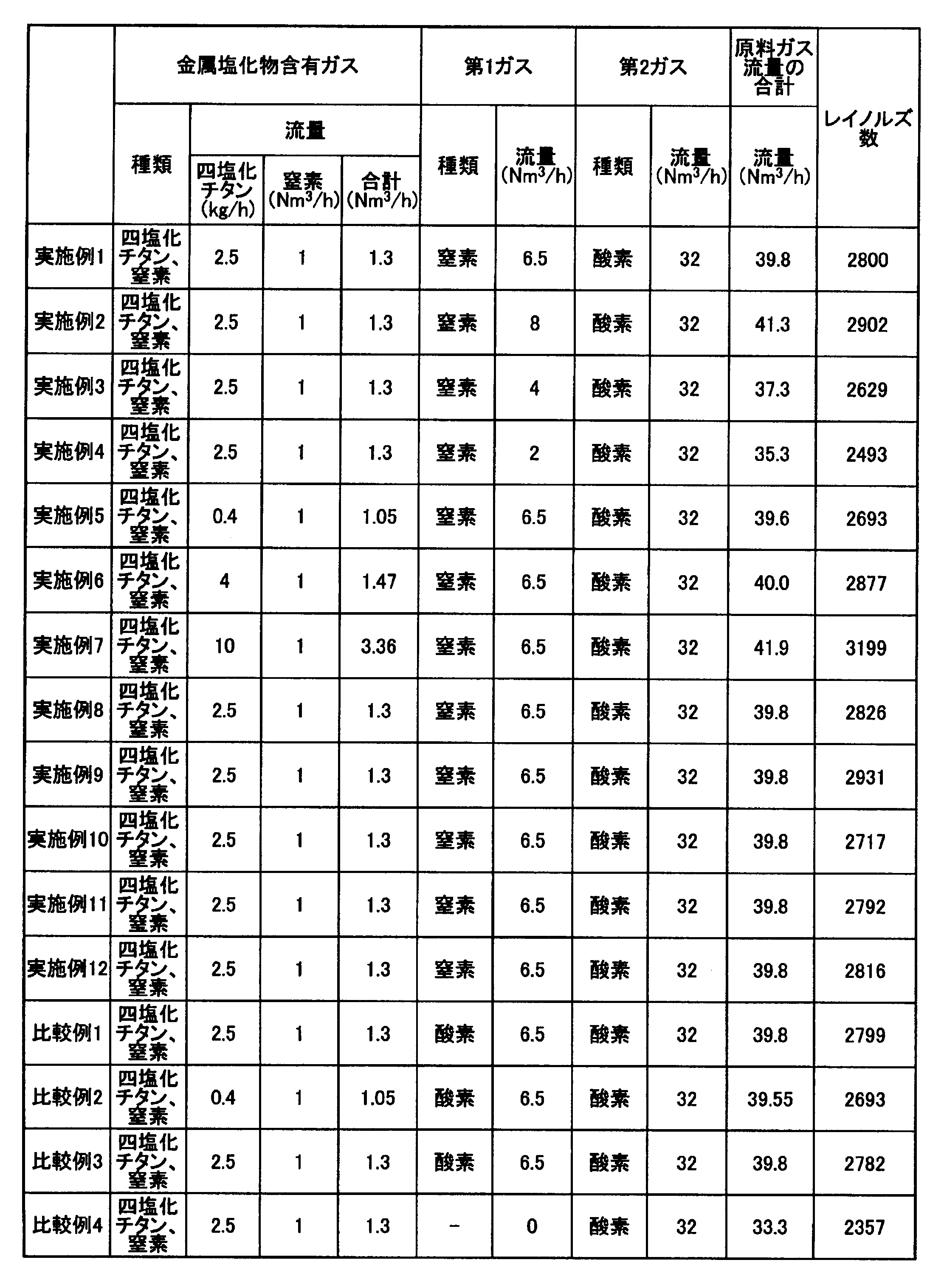
また、表3に、実施例1~12、比較例1~5の粉末生成物の収率と粉末生成物中の十面体比率、光触媒活性、比表面積(BET測定値、m2/g)、ルチル比率をまとめた。

第1支燃ガスに酸素を流す方式の比較例1~3においては、生産の初期には第1、第2中空内筒石英管への酸化チタン付着物がほとんど生成しないものの、生産を継続していくうちに、酸化チタン付着物が徐々に蓄積していき、生産時間が通算5~20時間の範囲内で流路が閉塞し、石英ガラスが破損した。このため、長時間の生産はできないことが分かった。
比較例3は、特許文献3(特開2011-184235号公報)の記載に従った製造方法であり、光触媒活性と粉末生成物の収率が高かった。
比較例1、2は、特開2011-184235号公報の製造方法よりも第1支燃ガスの温度が高いために、ルチル比率が高くなり、光触媒活性が低かった。
比較例4は第1支燃ガスを全く流さないために、第2支燃ガスの酸素の一部が第2中空内筒開口部27に逆流して流れ込みやすくなっており、第1、第2中空内筒石英管への酸化チタン付着物が生成され、流路閉塞により石英ガラスが破損した。
これに対し、予熱された四塩化チタン含有ガス及び第1ガスG2に酸素、水蒸気を含まない実施例1~12は、第1、第2中空内筒石英管への酸化チタン付着物が発生せず、95%以上の高収率で長時間、少なくとも通算で100時間の生産が可能であることが分かった。
比較例3は、特許文献3(特開2011-184235号公報)の記載に従った製造方法であり、光触媒活性と粉末生成物の収率が高かった。
比較例1、2は、特開2011-184235号公報の製造方法よりも第1支燃ガスの温度が高いために、ルチル比率が高くなり、光触媒活性が低かった。
比較例4は第1支燃ガスを全く流さないために、第2支燃ガスの酸素の一部が第2中空内筒開口部27に逆流して流れ込みやすくなっており、第1、第2中空内筒石英管への酸化チタン付着物が生成され、流路閉塞により石英ガラスが破損した。
これに対し、予熱された四塩化チタン含有ガス及び第1ガスG2に酸素、水蒸気を含まない実施例1~12は、第1、第2中空内筒石英管への酸化チタン付着物が発生せず、95%以上の高収率で長時間、少なくとも通算で100時間の生産が可能であることが分かった。
実施例1~4では第1ガスG2の流量を変えることで、第1ゾーンBにおける第1合流ガスの滞留時間を変えて、得られる酸化チタン粒子の特性比較を行った。
実施例1の32ミリ秒に対して、47ミリ秒(実施例3)、75ミリ秒(実施例4)と長くしていくと、ルチル比率が4%から6%へと若干増えて光触媒活性が若干低下した。逆に27ミリ秒(実施例2)と短くすると、ルチル比率は若干下がるものの、光触媒活性は若干下がった。
実施例1、5~7では四塩化チタンの流量を変えることで、第1合流ガス中における四塩化チタン濃度(体積%)を変えて得られる酸化チタン粒子の特性比較を行った。実施例1の3.8%に対して、第1合流ガス中における四塩化チタン濃度を0.6%とした実施例5は、BET値が増えて、光触媒活性が若干高まった。実施例1の3.8%に対して、第1合流ガス中における四塩化チタン濃度を5.9%(実施例6)、13.6%(実施例7)と濃度を高めていくと、BET値が14m2/gから9m2/gまで低下し、ルチル比率が4%から8%まで上がる結果、光触媒活性が低下した。これより、第1合流ガス中における四塩化チタン濃度は、0.1~20体積%とすることが好ましく、0.5~10体積%とすることがより好ましく、0.5~5体積%とすることが更に好ましい。
実施例1、8では第1ガスG2の予熱温度を変えて得られる酸化チタン粒子の特性比較を行った。第1ガスG2の予熱温度を1010℃とした実施例1に対して、900℃とした実施例8では、ルチル比は実施例1と同じで、光触媒活性は比較的高い結果が得られた。
実施例1の32ミリ秒に対して、47ミリ秒(実施例3)、75ミリ秒(実施例4)と長くしていくと、ルチル比率が4%から6%へと若干増えて光触媒活性が若干低下した。逆に27ミリ秒(実施例2)と短くすると、ルチル比率は若干下がるものの、光触媒活性は若干下がった。
実施例1、5~7では四塩化チタンの流量を変えることで、第1合流ガス中における四塩化チタン濃度(体積%)を変えて得られる酸化チタン粒子の特性比較を行った。実施例1の3.8%に対して、第1合流ガス中における四塩化チタン濃度を0.6%とした実施例5は、BET値が増えて、光触媒活性が若干高まった。実施例1の3.8%に対して、第1合流ガス中における四塩化チタン濃度を5.9%(実施例6)、13.6%(実施例7)と濃度を高めていくと、BET値が14m2/gから9m2/gまで低下し、ルチル比率が4%から8%まで上がる結果、光触媒活性が低下した。これより、第1合流ガス中における四塩化チタン濃度は、0.1~20体積%とすることが好ましく、0.5~10体積%とすることがより好ましく、0.5~5体積%とすることが更に好ましい。
実施例1、8では第1ガスG2の予熱温度を変えて得られる酸化チタン粒子の特性比較を行った。第1ガスG2の予熱温度を1010℃とした実施例1に対して、900℃とした実施例8では、ルチル比は実施例1と同じで、光触媒活性は比較的高い結果が得られた。
実施例1、8より、高い光触媒活性を得るには、第1ガスG2の予熱温度が800℃以上1050℃以下の範囲にあることが好ましく、850℃以上1050℃以下の範囲にあることがより好ましい。
実施例1、8~10を用いて、第2ガスG3の予熱温度を変えて得られる酸化チタン粒子の特性比較を行った。第1ガスG2の予熱温度を900℃、第2ガスG3の予熱温度を1030℃とした実施例8に対して、第1ガスG2の予熱温度を900℃、第2ガスG3の予熱温度を950℃とした実施例9は、ルチル比率は若干下がるものの、光触媒活性は若干低下した。第2ガスG3の予熱温度を1100℃とした実施例10では1030℃とした実施例1と比較するとルチル比率が高くなった結果、十面体比率が低下し、光触媒活性が低下した。
これより、第2ガスG3の予熱温度は、900℃以上1100℃以下の範囲にあることが好ましく、950℃以上1050℃以下の範囲にあることがさらに好ましい。
これより、第2ガスG3の予熱温度は、900℃以上1100℃以下の範囲にあることが好ましく、950℃以上1050℃以下の範囲にあることがさらに好ましい。
実施例1、11、12を用いて、金属塩化物含有ガスG1の温度を変えて得られる酸化チタン粒子の特性比較を行った。実施例1の880℃に対して、980℃(実施例11)に上げるとルチル比率が4%から5%へ若干増えて光触媒活性が低下した。
逆に650℃に下げると、ルチル比率は4%から3%へ下がり、光触媒活性は比較的高い結果が得られた。
これより、金属塩化物含有ガスG1の予熱温度は、600℃以上1000℃以下の範囲にあることが好ましく、600℃以上950℃以下の範囲にあることがより好ましく、800℃以上950℃以下の範囲にあることがさらに好ましい。
逆に650℃に下げると、ルチル比率は4%から3%へ下がり、光触媒活性は比較的高い結果が得られた。
これより、金属塩化物含有ガスG1の予熱温度は、600℃以上1000℃以下の範囲にあることが好ましく、600℃以上950℃以下の範囲にあることがより好ましく、800℃以上950℃以下の範囲にあることがさらに好ましい。
実施例1、8、11、12を用いて、第1合流ガスの温度を変えて得られる酸化チタン粒子の特性比較を行った。
実施例8は、実施例1よりも第1ガスG2の予熱温度を下げることで、第1合流ガスの温度を下げた。具体的には、実施例1において第1合流ガスの温度を979℃としたのに対して、実施例8において第1合流ガスの温度を895℃に下げたが、比較的高い光触媒活性が得られた。
実施例12は、実施例1よりも金属塩化物含有ガスG1の予熱温度を下げることで、第1合流ガスの温度を下げた。具体的には、実施例1において第1合流ガスの温度を979℃としたのに対して、実施例12において第1合流ガスの温度を925℃に下げたが、比較的高い光触媒活性が得られた。
実施例11は、実施例1よりも金属塩化物含有ガスG1の予熱温度を上げることで、第1合流ガスの温度を上げた。実施例1において第1合流ガスの温度を979℃とした場合にルチル比率が4%であったのに対して、実施例11において第1合流ガスの温度を1003℃に上げた場合にルチル比率も5%に上がり、光触媒活性は低下した。
これより、第1合流ガスの温度は800℃以上1050℃以下の温度範囲とすることが好ましく、850℃以上1000℃以下の温度範囲がより好ましく、さらに好ましくは、900℃以上1000℃以下が好ましい。
これより、第1合流ガスの温度は800℃以上1050℃以下の温度範囲とすることが好ましく、850℃以上1000℃以下の温度範囲がより好ましく、さらに好ましくは、900℃以上1000℃以下が好ましい。
実施例1、9、10では第2合流ガスの温度を変えて得られる酸化チタン粒子の特性比較を行った。実施例1では第2合流ガスの温度を1020℃としたのに対して、実施例9では第2合流ガスの温度を939℃に下げたが、光触媒活性は若干下がる程度であった。
また、実施例1では第2合流ガスの温度を1020℃とした場合にルチル比率が4%であったのに対して、実施例10では第2合流ガスの温度を1076℃に上げた場合にルチル比率が12%に上がり、光触媒活性は大幅に低下した。
これより、第2合流ガスの温度は800℃以上1100℃以下の温度範囲とすることが好ましく、800℃以上1050℃以下の温度範囲がより好ましく、さらに好ましくは、850℃以上1050℃以下が好ましい。
また、実施例1では第2合流ガスの温度を1020℃とした場合にルチル比率が4%であったのに対して、実施例10では第2合流ガスの温度を1076℃に上げた場合にルチル比率が12%に上がり、光触媒活性は大幅に低下した。
これより、第2合流ガスの温度は800℃以上1100℃以下の温度範囲とすることが好ましく、800℃以上1050℃以下の温度範囲がより好ましく、さらに好ましくは、850℃以上1050℃以下が好ましい。
本発明は、金属酸化物粒子の製造方法及びその製造装置に関するものであって、特に、高い光触媒活性を有する酸化チタンを、長時間生産することを可能とする酸化チタン粒子の製造方法に関するものであって、光触媒産業などにおいて利用可能性がある。
1…中空外筒、1a…上流側、1b…下流側、2…断熱材(セラミックファイバ)、3…生成物回収部、3a…排気ポンプ、3b…圧力調整バルブ、4…第1中空内筒、4a…上流側、4b…下流端(第1合流地点)、5…第2中空内筒、5a…上流側、5b…下流端(第2合流地点)、6…排出管、11…反応管、15…第1導管、16…第2導管、24…第1中空内筒開口部、25、26…リング状開口部、27…第2中空内筒開口部、28…中空外筒開口部、101…金属酸化物粒子の製造装置、A…第2反応ゾーン、B…第1ゾーン、G1…金属塩化物含有ガス、G2…第1ガス、G3…第2ガス、X…予熱領域、Y…予熱領域、Z…予熱領域。
Claims (14)
- 反応管内で、予熱された金属塩化物含有ガスに、前記金属塩化物を含まない予熱された第1ガスを第1合流地点で合流させて第1合流ガスとし、該第1合流ガスに、前記金属塩化物を含まない予熱された第2ガスを、前記第1合流地点よりも下流側に離れた第2合流地点で合流して第2合流ガスとする工程を含む金属酸化物粒子の製造方法であって、
前記金属塩化物含有ガス及び前記第1ガスの両方とも酸素、水蒸気を含有せず、
前記第2ガスは少なくとも酸素を含有しており、
前記第1ガスの予熱温度を、前記金属塩化物含有ガスの予熱温度以上の温度として前記第1ガスを前記第1合流地点で合流させることで、前記第1合流地点から前記第2合流地点までの間(第1ゾーンと呼ぶ)において、予熱された前記金属塩化物含有ガスをさらに加熱し、前記第2ガスの予熱温度を、前記第1合流ガスの温度以上の温度として前記第1合流ガスと合流させることで、前記第2合流地点から下流側において、前記第1合流ガスをさらに加熱することを特徴とする金属酸化物粒子の製造方法。 - 前記金属塩化物が四塩化チタンであり、前記金属酸化物粒子が酸化チタン粒子であることを特徴とする請求項1に記載の金属酸化物粒子の製造方法。
- 前記酸化チタン粒子が十面体酸化チタン粒子であることを特徴とする請求項2に記載の金属酸化物粒子の製造方法。
- 前記金属塩化物含有ガスの予熱温度が600℃以上1000℃以下であることを特徴とする請求項1~3のいずれか1項に記載の金属酸化物粒子の製造方法。
- 前記第1合流ガスの温度が800℃以上1050℃以下であることを特徴とする請求項1~3のいずれか1項に記載の金属酸化物粒子の製造方法。
- 前記第2合流ガスの温度が800℃以上1100℃以下であることを特徴とする請求項1~3のいずれか1項に記載の金属酸化物粒子の製造方法。
- 前記第1ガスの予熱温度が800℃以上1050℃以下であることを特徴とする請求項1~3のいずれか1項に記載の金属酸化物粒子の製造方法。
- 前記第2ガスの予熱温度が900℃以上1100℃以下であることを特徴とする請求項1~3のいずれか1項に記載の金属酸化物粒子の製造方法。
- 前記金属塩化物含有ガスが、窒素ガスを含むことを特徴とする請求項1~3のいずれか1項に記載の金属酸化物粒子の製造方法。
- 前記第1ガスが、窒素ガス及びアルゴンからなる群から選ばれた1種以上のガスを含むことを特徴とする請求項1~3のいずれか1項に記載の金属酸化物粒子の製造方法。
- 前記第2ガスが、酸素ガスとともに、窒素ガス、アルゴン及び水蒸気からなる群から選ばれた1種以上のガスを含むことを特徴とする請求項1~3のいずれか1項に記載の金属酸化物粒子の製造方法。
- 前記第1合流ガスに含まれる前記四塩化チタンの濃度を0.1~20体積%とすることを特徴とする請求項2または3のいずれかに記載の金属酸化物粒子の製造方法。
- 前記第1合流ガスが、前記第1ゾーンにおいて滞留する時間を2~100ミリ秒とすることを特徴とする請求項1~3のいずれか1項に記載の金属酸化物粒子の製造方法。
- 前記第2合流ガスのレイノルズ数を10~10000とすることを特徴とする請求項1~3のいずれか1項に記載の金属酸化物粒子の製造方法。
Priority Applications (1)
| Application Number | Priority Date | Filing Date | Title |
|---|---|---|---|
| JP2016569311A JPWO2016114177A1 (ja) | 2015-01-14 | 2016-01-05 | 金属酸化物粒子の製造方法 |
Applications Claiming Priority (2)
| Application Number | Priority Date | Filing Date | Title |
|---|---|---|---|
| JP2015-005149 | 2015-01-14 | ||
| JP2015005149 | 2015-01-14 |
Publications (1)
| Publication Number | Publication Date |
|---|---|
| WO2016114177A1 true WO2016114177A1 (ja) | 2016-07-21 |
Family
ID=56405724
Family Applications (1)
| Application Number | Title | Priority Date | Filing Date |
|---|---|---|---|
| PCT/JP2016/050146 Ceased WO2016114177A1 (ja) | 2015-01-14 | 2016-01-05 | 金属酸化物粒子の製造方法 |
Country Status (3)
| Country | Link |
|---|---|
| JP (1) | JPWO2016114177A1 (ja) |
| TW (1) | TW201641416A (ja) |
| WO (1) | WO2016114177A1 (ja) |
Citations (2)
| Publication number | Priority date | Publication date | Assignee | Title |
|---|---|---|---|---|
| JP2010095401A (ja) * | 2008-10-15 | 2010-04-30 | Showa Denko Kk | 金属酸化物粒子の製造方法及び製造装置 |
| JP2011184235A (ja) * | 2010-03-08 | 2011-09-22 | Hokkaido Univ | 金属酸化物粒子の製造方法及び製造装置 |
-
2016
- 2016-01-05 WO PCT/JP2016/050146 patent/WO2016114177A1/ja not_active Ceased
- 2016-01-05 JP JP2016569311A patent/JPWO2016114177A1/ja not_active Withdrawn
- 2016-01-08 TW TW105100537A patent/TW201641416A/zh unknown
Patent Citations (2)
| Publication number | Priority date | Publication date | Assignee | Title |
|---|---|---|---|---|
| JP2010095401A (ja) * | 2008-10-15 | 2010-04-30 | Showa Denko Kk | 金属酸化物粒子の製造方法及び製造装置 |
| JP2011184235A (ja) * | 2010-03-08 | 2011-09-22 | Hokkaido Univ | 金属酸化物粒子の製造方法及び製造装置 |
Also Published As
| Publication number | Publication date |
|---|---|
| TW201641416A (zh) | 2016-12-01 |
| JPWO2016114177A1 (ja) | 2017-09-28 |
Similar Documents
| Publication | Publication Date | Title |
|---|---|---|
| JP7732612B2 (ja) | 酸化チタン粒子及びその製造方法 | |
| JPWO2012070461A1 (ja) | 金属チタン製造装置および金属チタンの製造方法 | |
| JP5669057B2 (ja) | 酸化チタン粒子の製造方法及び製造装置 | |
| TWI382960B (zh) | 金屬氧化物粒子之製造方法及製造裝置 | |
| JP5682929B2 (ja) | 酸化チタン粒子の製造方法及び製造装置 | |
| WO2016114177A1 (ja) | 金属酸化物粒子の製造方法 | |
| WO2010023757A1 (ja) | 酸化チタン粒子の製造方法 | |
| JP2001287996A (ja) | アナターゼ型酸化チタン単結晶 | |
| JP4997552B2 (ja) | 酸化チタン粒子の製造方法 | |
| JP3949143B2 (ja) | 二酸化チタンナノ光触媒粉体、その製法及び装置 | |
| KR20200081724A (ko) | Rf 플라즈마를 이용한 삼산화텅스텐 나노분말의 제조방법 | |
| JP2025065778A (ja) | 酸化チタン粒子及びその製造方法 | |
| JP2025065787A (ja) | 酸化チタン粒子及びその製造方法 | |
| JP2005139033A (ja) | シリコンクラスタ内包シリコン酸化物の製造方法 |
Legal Events
| Date | Code | Title | Description |
|---|---|---|---|
| 121 | Ep: the epo has been informed by wipo that ep was designated in this application |
Ref document number: 16737248 Country of ref document: EP Kind code of ref document: A1 |
|
| ENP | Entry into the national phase |
Ref document number: 2016569311 Country of ref document: JP Kind code of ref document: A |
|
| NENP | Non-entry into the national phase |
Ref country code: DE |
|
| 122 | Ep: pct application non-entry in european phase |
Ref document number: 16737248 Country of ref document: EP Kind code of ref document: A1 |