WO2016114155A1 - 画像処理装置、画像処理方法、プログラム、及び、内視鏡システム - Google Patents
画像処理装置、画像処理方法、プログラム、及び、内視鏡システム Download PDFInfo
- Publication number
- WO2016114155A1 WO2016114155A1 PCT/JP2016/050016 JP2016050016W WO2016114155A1 WO 2016114155 A1 WO2016114155 A1 WO 2016114155A1 JP 2016050016 W JP2016050016 W JP 2016050016W WO 2016114155 A1 WO2016114155 A1 WO 2016114155A1
- Authority
- WO
- WIPO (PCT)
- Prior art keywords
- image
- parallax
- parallax amount
- pixel
- unit
- Prior art date
Links
Images


Classifications
-
- H—ELECTRICITY
- H04—ELECTRIC COMMUNICATION TECHNIQUE
- H04N—PICTORIAL COMMUNICATION, e.g. TELEVISION
- H04N13/00—Stereoscopic video systems; Multi-view video systems; Details thereof
- H04N13/10—Processing, recording or transmission of stereoscopic or multi-view image signals
- H04N13/106—Processing image signals
- H04N13/128—Adjusting depth or disparity
-
- A—HUMAN NECESSITIES
- A61—MEDICAL OR VETERINARY SCIENCE; HYGIENE
- A61B—DIAGNOSIS; SURGERY; IDENTIFICATION
- A61B1/00—Instruments for performing medical examinations of the interior of cavities or tubes of the body by visual or photographical inspection, e.g. endoscopes; Illuminating arrangements therefor
- A61B1/00002—Operational features of endoscopes
- A61B1/00004—Operational features of endoscopes characterised by electronic signal processing
- A61B1/00009—Operational features of endoscopes characterised by electronic signal processing of image signals during a use of endoscope
- A61B1/000095—Operational features of endoscopes characterised by electronic signal processing of image signals during a use of endoscope for image enhancement
-
- A—HUMAN NECESSITIES
- A61—MEDICAL OR VETERINARY SCIENCE; HYGIENE
- A61B—DIAGNOSIS; SURGERY; IDENTIFICATION
- A61B1/00—Instruments for performing medical examinations of the interior of cavities or tubes of the body by visual or photographical inspection, e.g. endoscopes; Illuminating arrangements therefor
- A61B1/00064—Constructional details of the endoscope body
- A61B1/00071—Insertion part of the endoscope body
- A61B1/0008—Insertion part of the endoscope body characterised by distal tip features
- A61B1/00087—Tools
-
- A—HUMAN NECESSITIES
- A61—MEDICAL OR VETERINARY SCIENCE; HYGIENE
- A61B—DIAGNOSIS; SURGERY; IDENTIFICATION
- A61B1/00—Instruments for performing medical examinations of the interior of cavities or tubes of the body by visual or photographical inspection, e.g. endoscopes; Illuminating arrangements therefor
- A61B1/00163—Optical arrangements
- A61B1/00193—Optical arrangements adapted for stereoscopic vision
-
- A—HUMAN NECESSITIES
- A61—MEDICAL OR VETERINARY SCIENCE; HYGIENE
- A61B—DIAGNOSIS; SURGERY; IDENTIFICATION
- A61B1/00—Instruments for performing medical examinations of the interior of cavities or tubes of the body by visual or photographical inspection, e.g. endoscopes; Illuminating arrangements therefor
- A61B1/04—Instruments for performing medical examinations of the interior of cavities or tubes of the body by visual or photographical inspection, e.g. endoscopes; Illuminating arrangements therefor combined with photographic or television appliances
-
- H—ELECTRICITY
- H04—ELECTRIC COMMUNICATION TECHNIQUE
- H04N—PICTORIAL COMMUNICATION, e.g. TELEVISION
- H04N13/00—Stereoscopic video systems; Multi-view video systems; Details thereof
- H04N13/20—Image signal generators
- H04N13/204—Image signal generators using stereoscopic image cameras
Definitions
- the present technology relates to an image processing device, an image processing method, a program, and an endoscope system, and in particular, for example, an image processing device, an image processing method, a program, and a program capable of reducing a user's burden.
- the present invention relates to an endoscope system.
- the 3D (Dimensions) image of the human body (inside) is used to smoothly guide the treatment tool in the depth direction during procedures such as surgery and diagnosis using the endoscope.
- it is required to display a 3D endoscopic image obtained as a result (see, for example, Patent Document 1).
- the user can obtain information in the depth direction by observing the 3D endoscopic image. For this reason, for example, the treatment instrument can be guided smoothly in the depth direction. can do.
- the 3D endoscopic image includes, for example, a left eye image observed with the user's left eye and a right eye image observed with the user's right eye.
- the left eye image and the right eye image constituting the 3D endoscopic image have parallax, and this parallax allows the user observing the 3D endoscopic image to display information in the depth direction. Perceive.
- a user who observes a 3D endoscopic image can perceive information in the depth direction based on the parallax of the 3D endoscopic image, but observes the 3D endoscopic image. In doing so, the user may feel discomfort or discomfort unique to 3D, which may be a burden on the user.
- a 3D endoscopic image for example, when an object that moves rapidly is shown, or when the front part of an object that extends from the front to the back moves, observe the 3D endoscopic image. The user who is doing this may feel burdened.
- This technology has been made in view of such a situation, and is intended to reduce the burden on the user.
- the image processing apparatus or the program of the present technology adjusts the parallax amount of the 3D biological image according to whether or not the parallax of the 3D (Dimensions) biological image obtained by imaging the biological body is a burden on the user.
- An image processing apparatus including an adjustment unit, or a program for causing a computer to function as such an image processing apparatus.
- the image processing method includes a step of adjusting the amount of parallax of the 3D biological image according to whether or not the parallax of the 3D (Dimensions) biological image obtained by imaging the biological body is a burden on the user. It is.
- the endoscope system of the present technology is an endoscope that captures a 3D (Dimensions) image, and whether or not the parallax between the 3D biological image obtained by imaging the living body with the endoscope is a burden on the user And a display unit for displaying the 3D biological image whose parallax amount is adjusted by the parallax amount adjusting unit.
- 3D Dissions
- the image processing device the image processing method, the program, and the endoscope system of the present technology, depending on whether or not the parallax of the 3D (Dimensions) biological image obtained by imaging the living body is a burden on the user, the 3D The parallax amount of the biological image is adjusted.
- the image processing apparatus may be an independent apparatus or an internal block constituting one apparatus.
- the program can be provided by being transmitted through a transmission medium or by being recorded on a recording medium.
- FIG. 10 is a flowchart illustrating an example of image display processing for displaying a 3D endoscopic image.
- 12 is a flowchart for describing an example of processing for adjusting a parallax amount of a 3D endoscopic image.
- FIG. 3 is a block diagram illustrating a configuration example of a parallax amount adjustment unit 40.
- FIG. 3 is a block diagram illustrating a configuration example of a frame difference calculation unit 41.
- FIG. 12 is a flowchart for describing an example of processing for adjusting a parallax amount of a 3D endoscopic image.
- FIG. 12 is a flowchart for describing an example of processing for adjusting a parallax amount of a 3D endoscopic image. It is a flowchart explaining the example of a process of forceps area
- FIG. 18 is a block diagram illustrating a configuration example of an embodiment of a computer to which the present technology is applied.
- FIG. 1 is a block diagram illustrating a configuration example of a first embodiment of an endoscope system to which the present technology is applied.
- the endoscope system includes an endoscope 11, a parallax amount adjustment unit 12, a display unit 13, an electric knife 14, an electric knife switch 15, and an electric knife control unit 16.
- the endoscope 11 is inserted into a body cavity of a patient (human body), for example, and captures an endoscopic image that is a 3D image with tissue in the body cavity as a subject.
- the endoscope 11 includes, for example, a camera head 11A held by an operator (doctor) who performs an operation as a user of the endoscope system in appearance, and an endoscope scope inserted into the patient's body. 11B.
- endoscopic surgery that is, surgery using an endoscope system
- the endoscope scope 11B is inserted into the body, and the user operates the endoscope 11 with the camera head 11A.
- the endoscope 11 for example, light is irradiated from the distal end of the endoscope scope 11B, and the surgical part (tissue) serving as a subject in the patient's body is illuminated by the light.
- the light that illuminates the subject is reflected by the subject, and the reflected light from the subject enters from the tip of the endoscope scope 11B.
- light incident from the distal end of the endoscope scope 11 ⁇ / b> B is received and photoelectrically converted, whereby a 3D endoscope image of the subject is captured.
- the 3D endoscopic image captured by the endoscope 11 includes an image signal L of the left eye image observed with the left eye and an image signal R of the right eye image observed with the right eye. Is done.
- the left eye image and the right eye image have parallax, and the user perceives information in the depth direction by observing the left eye image and the right eye image having such parallax with the left eye and the right eye, respectively. be able to.
- the image signal L of the left eye image and the image signal R of the right eye image constituting the 3D endoscopic image captured by the endoscope 11 are supplied to the parallax amount adjustment unit 12.
- the parallax amount adjustment unit 12 determines whether the parallax of the 3D endoscopic image (the image signals L and R thereof) from the endoscopic image 11 is a burden on the user who observes the endoscopic image. The parallax amount of the 3D endoscopic image from the endoscopic image 11 is adjusted so as to reduce the burden on the user.
- the parallax amount adjustment unit 12 based on the electric knife control information supplied from the electric knife control unit 16, the 3D endoscope image from the endoscope image 11. It is detected (determined) whether or not the parallax is a burden on the user.
- the parallax amount adjusting unit 12 performs the parallax amount of the 3D endoscopic image from the endoscopic image 11. Is adjusted so that the parallax is reduced.
- the parallax amount adjustment unit 12 includes an image signal L of a left eye image (hereinafter, also referred to as an adjustment image signal L) and an image signal R of a right eye image that configure a 3D endoscopic image after adjusting the parallax amount. (Hereinafter also referred to as an adjusted image signal R) is supplied to the display unit 13.
- the display unit 13 is a display device that can display a 3D image, such as a head-mounted display, and displays a 3D endoscopic image supplied from the parallax amount adjustment unit 12.
- a display method of the (adjustment) image signal L of the left eye image and the image signal R of the (adjustment) right eye image constituting the 3D endoscopic image for example, a side-by-side method, a line-by-line method, a frame There are sequential methods.
- a display method for displaying a 3D image on the display unit 13 is not particularly limited.
- the electric knife 14 is a treatment tool capable of performing a surgical operation for incising a human tissue by flowing a high-frequency current supplied from the electric knife control unit 16 through the human body.
- a tool used to perform some kind of treatment in an operation or diagnosis using an endoscope system is referred to as a treatment tool.
- a surgical instrument Is called a surgical instrument.
- the electric knife 14 is one of surgical instruments called an energy device. Examples of the energy device include a device using an ultrasonic wave as well as a device using an electric current such as the electric knife 14.
- the electric knife switch 15 is operated by, for example, a user when turning on or off the current flowing through the electric knife 14.
- the electric knife control signal corresponding to the operation is supplied to the electric knife controller 16.
- the electric knife control unit 16 turns on or off the supply of high-frequency current to the electric knife 14 in accordance with the electric knife control signal supplied from the electric knife switch 15. Further, the electric knife control unit 16 supplies electric parallax control information indicating that the electric knife 14 is turned on or off to the parallax amount adjustment unit 12 according to the electric knife control signal.
- a user inserts an endoscope scope 11B into a patient's body, and the endoscope 11 is a surgical part (a subject in the patient's body). A 3D endoscopic image of the tissue is captured.
- the 3D endoscopic image captured by the endoscope 11 (the image signal L of the left eye image and the image signal R of the right eye image constituting the 3D image) is supplied from the endoscope 11 to the parallax amount adjustment unit 12. Further, the parallax amount adjustment unit 12 supplies the display unit 13 with the display.
- the electric scalpel control signal indicating on is It is supplied to the knife control unit 16.
- the electric knife control unit 16 turns on (starts) the supply of a high-frequency current to the electric knife 14 in response to an electric knife control signal indicating ON from the electric knife switch 15, whereby the user can 14 allows the patient's tissue to be incised.
- the electric knife control unit 16 supplies electric knife control information indicating ON / OFF of the electric knife 14 to the parallax amount adjustment unit 12.
- the electric knife control information indicates that the electric knife 14 is turned on. Therefore, when the electric knife 14 is used, the parallax amount adjustment unit 12 displays the parallax of the 3D endoscope image displayed on the display unit 13. Is a burden on the user, the parallax amount of the 3D endoscope image from the endoscope 11 is adjusted.
- mist and smoke are generated when the tissue of the human body is incised using the electric scalpel 14.
- mist and smoke generated when the electric knife 14 is used move vigorously and are reflected in the 3D endoscopic image close to the tip of the endoscope 11B, the 3D endoscopic image is observed. The user may feel uncomfortable with the mist and smoke that move rapidly.
- the user's discomfort caused by the intense movement of mist and smoke reflected in the 3D endoscopic image increases the burden on the user who observes the 3D endoscopic image, and the user may watch the part he / she originally wants to see Hinder.
- the parallax amount adjusting unit 12 is configured to reduce the burden on the user due to the mist and smoke generated by using the electric knife 14 being reflected in the 3D endoscope image.
- the parallax amount of the 3D endoscopic image from the endoscope 11 is adjusted so that the parallax becomes small.
- the display unit 13 displays a 3D endoscopic image in which the parallax amount is adjusted by the parallax amount adjusting unit 12.
- the electric knife 14 is used as the energy device.
- an energy device other than the electric knife 14 such as a device using ultrasonic waves is used in addition to the electric knife 14. can do.
- FIG. 2 is a diagram illustrating a schematic configuration example of the endoscope 11 that captures a 3D endoscope image.
- the endoscope 11 has two image sensors (image sensors) 21L and 21R.
- the image sensor 21L captures an image to be a left eye image.
- the imaging element 21R captures an image that is a right eye image.
- the image sensors 21L and 21R are arranged side by side in the horizontal (left and right) direction, whereby the left and right eye images with parallax are captured by the image sensors 21L and 21R, respectively.
- the image sensors 21L and 21R can be provided, for example, at the distal end portion of the endoscope scope 11B or the camera head 11A.
- a method for capturing a 3D image for example, there are a so-called two-lens image capturing method and a single-lens (monocular) image capturing method.
- a 3D endoscopic image is captured.
- the method for imaging is not particularly limited.
- FIG. 3 is a block diagram illustrating a configuration example of the parallax amount adjusting unit 12 in FIG.
- the parallax amount adjustment unit 12 includes development units 31L and 31R, image shift adjustment units 32L and 32R, image correction units 33L and 33R, a parallax image generation unit 34, and a parallax adjustment image generation unit 35.
- the image signal L of the left eye image constituting the 3D endoscope image is supplied from the endoscope 11 to the developing unit 31L.
- the left eye image and the right eye image constituting the 3D endoscope image captured by the endoscope 11 are so-called RAW images having a predetermined arrangement such as a Bayer arrangement.
- the developing unit 31L performs a developing process on the image signal L of the left eye image from the endoscope 11, and the image signal of each plane of R (red), G (green), and B (blue). Is generated and supplied to the image shift adjustment unit 32L and the parallax image generation unit 34.
- the image shift adjustment unit 32L is supplied with the development signal L of the left eye image from the development unit 31L, and is also supplied with a parallax adjustment image to be described later from the parallax adjustment image generation unit 35.
- the image shift adjustment unit 32L shifts the pixel value of the pixel of the left eye image (the development signal L) from the development unit 31L in accordance with the parallax adjustment image from the parallax adjustment image generation unit 35, thereby developing the image.
- the parallax amount of the 3D endoscopic image composed of the left eye image from the unit 31L is adjusted.
- the image shift adjustment unit 32L supplies the left eye image (image signal) after the pixel value shift to the image correction unit 33L.
- the image correcting unit 33L corrects the left eye image by interpolating missing pixels among the pixels constituting the left eye image after the pixel value is shifted from the image shift adjusting unit 32L.
- the image correction unit 33L corrects the left-eye image by interpolating the pixel value of the missing pixel of the left-eye image using a pixel value of a pixel that is near the missing pixel and is not a missing pixel. . Then, the image correction unit 33L converts the image signal of the left eye image after correction, that is, the image signal of the left eye image having no missing pixel, which constitutes the 3D endoscope image in which the parallax amount is adjusted, into the adjusted image.
- the signal L is supplied to the display unit 13.
- the image signal R of the right eye image that constitutes the 3D endoscope image is supplied from the endoscope 11 to the developing unit 31R.
- the developing unit 31R, the image shift adjusting unit 32R, and the image correcting unit 33R perform the same processes as the developing unit 31L, the image shift adjusting unit 32L, and the image correcting unit 33L, respectively.
- the developing unit 31R performs development processing on the image signal R of the right eye image from the endoscope 11, and generates a development signal R having image signals of R, G, and B planes. Then, the image is supplied to the image shift adjustment unit 32R and the parallax image generation unit 34.
- the image shift adjustment unit 32R shifts the pixel value of the pixel of the right eye image (the development signal R thereof) from the development unit 31R in the horizontal direction according to the parallax adjustment image from the parallax adjustment image generation unit 35, thereby developing the image.
- the parallax amount of the 3D endoscopic image composed of the right eye image from the unit 31R is adjusted.
- the image shift adjustment unit 32R supplies the right eye image (image signal) after the pixel value shift to the image correction unit 33R.
- the image correction unit 33R interpolates the missing pixels among the pixels constituting the right eye image after the pixel value shift from the image shift adjustment unit 32R, thereby obtaining the right eye image. Correct.
- the image correcting unit 33R displays, as the adjusted image signal R, the image signal of the right eye image that is included in the 3D endoscopic image in which the parallax amount is adjusted and is obtained by correcting the right eye image and has no missing pixels. To the unit 13.
- the parallax image generation unit 34 uses the left eye image (the development signal L) supplied from the development unit 31L and the right eye image (the development signal R) supplied from the development unit 31R, and outputs these left eyes. The amount of parallax between the image and the right eye image is detected.
- the parallax image generation unit 34 is one of the left eye image from the development unit 31L and the right eye image from the development unit 31R, for example, the left eye image with reference to the left eye image. Corresponding corresponding pixels in the right eye image are detected for each of the pixels.
- the parallax image generation unit 34 sequentially selects each pixel of the left eye image as a target pixel of interest, and detects a corresponding pixel corresponding to the target pixel from the pixels of the right eye image.
- Corresponding pixels can be detected, for example, by performing block matching or the like that searches a block similar to the block including the target pixel in the right eye image in the horizontal direction.
- the parallax image generation unit 34 detects a shift amount of the position of the corresponding pixel from the position corresponding to the target pixel in the right eye image as a parallax amount between the target pixel and the corresponding pixel, and the parallax amount is determined as the pixel value. A parallax image to be generated is generated.
- the parallax image generation unit 34 generates, as a parallax image, an image in which the parallax amount detected for the target pixel is the pixel value of the pixel at the position of the target pixel.
- the parallax image generation unit 34 supplies the parallax image to the parallax adjustment image generation unit 35.
- the parallax adjustment image generation unit 35 uses the parallax image from the parallax image generation unit 34 to generate a parallax adjustment image having a parallax adjustment value for adjusting the parallax amount that is a pixel value of the parallax image as a pixel value. .
- the electric knife control information is supplied from the electric knife control unit 16 to the parallax amount adjustment image generation unit 35.
- the parallax amount adjustment image generation unit 35 generates a parallax adjustment image using the parallax image from the parallax image generation unit 34 based on the electric knife control information.
- parallax amount which is the pixel value of the pixel at the position (x, y) of the parallax image
- d (x, y) the pixel at the position (x, y) of the parallax adjustment image
- a parallax adjustment value that is a pixel value is represented as c (x, y).
- the parallax adjustment image generation unit 35 obtains a parallax adjustment value c (x, y) for adjusting the parallax amount d (x, y) according to, for example, the equation (1) or the equation (2).
- Equation (1) a is a constant equal to or greater than 1, and for example, the value is experimentally determined by the developer of the endoscope system.
- parallax adjustment value c (x, y) is obtained according to the equation (1) or the equation (2) is controlled based on the electric knife control information.
- the parallax adjustment value c (x, y) is obtained according to the equation (1).
- the parallax adjustment value c (x, y) is obtained according to the equation (2).
- Equation (1) as the parallax adjustment value c (x, y), a value ((d (x, y) ⁇ d (x, y) / a) / 2) is required. Further, according to Equation (2), 0 is obtained as the parallax adjustment value c (x, y).
- the parallax adjustment image generation unit 35 generates a parallax adjustment image having the above-described parallax adjustment value c (x, y) as a pixel value, and supplies the parallax adjustment image to the image shift adjustment units 32L and 32R.
- the pixel values of the pixels of the left eye image and the right eye image are shifted in the horizontal direction in accordance with the parallax adjustment image supplied from the parallax adjustment image generation unit 35 as described above.
- the parallax amount of the 3D endoscopic image composed of the left eye image and the right eye image is adjusted.
- FIG. 4 is a diagram for explaining the adjustment of the amount of parallax by the shift of the pixel value in the image shift adjustment units 32L and 32R.
- the pixel at the position (x, y) of the development signal L of the left eye image be the target pixel
- the pixel value of the target pixel is represented as l (x, y)
- the development signal R of the right eye image The pixel value of the corresponding pixel corresponding to the target pixel is represented as r (x, y).
- the image shift adjustment unit 32L converts the pixel value l (x, y) of the target pixel of the development signal L of the left eye image into the parallax adjustment value c () that is the pixel value of the pixel at the position (x, y) of the parallax adjustment image.
- the amount of parallax between the target pixel and the corresponding pixel is adjusted by shifting in the horizontal direction according to x, y).
- the image shift adjustment unit 32L for example, in accordance with Expression (3), the pixel value l ′ () at the position where the pixel value l (x, y) of the target pixel is shifted in the horizontal direction by ⁇ c (x, y). Let xc (x, y), y).
- the image shift adjustment unit 32R uses the pixel value r (x, y) of the corresponding pixel of the development signal R of the right eye image as the pixel value of the pixel at the position (x, y) of the parallax adjustment image.
- the amount of parallax between the target pixel and the corresponding pixel is adjusted by shifting in the horizontal direction according to the value c (x, y).
- the image shift adjustment unit 32R for example, according to the equation (4), the pixel value r ′ () at the position where the pixel value r (x, y) of the corresponding pixel is shifted in the horizontal direction by + c (x, y). Let x + c (x, y), y).
- the parallax adjustment value c (x, y) is greater than 0, the shifted pixel values l ′ (xc (x, y), y) and r ′ (x + c (x, y), y ) Is smaller than the parallax between the pixel values l (x, y) and r (x, y) before the shift, and thus the user's burden felt by the parallax can be reduced. .
- each pixel of the development signal L of the left eye image is sequentially set as the target pixel, and the pixel value of each pixel of the development signal L of the left eye image and the development signal R of the right eye image is shifted. To do.
- the image shift adjustment unit 32L supplies an image signal obtained by shifting the pixel value of each pixel of the development signal L of the left eye image to the image correction unit 33L as the adjustment development signal L of the left eye image.
- the image shift adjustment unit 32R supplies an image signal obtained by shifting the pixel value of each pixel of the development signal R of the right eye image to the image correction unit 33R as the adjustment development signal R of the right eye image.
- the parallax adjustment value c (x, y) becomes 0 according to the equation (2), so that the image shift adjustment units 32L and 32R The parallax amount is not substantially adjusted by shifting the pixel value.
- the parallax adjustment value c (x, y) is obtained according to the equation (1), and the parallax adjustment value c (x, y) is obtained in the image shift adjustment units 32L and 32R. Accordingly, the amount of parallax is adjusted so that the parallax is reduced by shifting the pixel value.
- the user's discomfort caused by the intense movement of mist and smoke reflected in the 3D endoscopic image increases the burden on the user who observes the 3D endoscopic image, and the user may watch the part he / she originally wants to see Hinder.
- the parallax amount of the 3D endoscopic image is adjusted so that the parallax becomes small as described above.
- the burden on the user who observes the image can be reduced.
- FIG. 5 is a flowchart illustrating an example of image display processing for displaying a 3D endoscope image in the endoscope system of FIG.
- step S1 the endoscope 11 is inserted into a body cavity of a patient (human body), for example, and captures a 3D endoscopic image with a tissue in the body cavity as a subject, and configures the 3D endoscopic image.
- the image signal L of the left eye image and the image signal R of the right eye image to be supplied are supplied to the parallax amount adjustment unit 12.
- step S1 the process proceeds from step S1 to step S2, and the parallax amount adjustment unit 12 adjusts the parallax amount of the 3D endoscopic image (image signals L and R thereof) from the endoscopic image 11, and the parallax thereof.
- the 3D endoscopic images (adjusted image signals L and R thereof) after the amount adjustment are supplied to the display unit 13.
- the parallax amount adjusting unit 12 When the parallax of the 3D endoscopic image from the endoscopic image 11 is a burden for the user who observes the endoscopic image, the parallax amount adjusting unit 12 The amount of parallax is adjusted so that the parallax is reduced. Then, the parallax amount adjustment unit 12 supplies the display unit 13 with the 3D endoscopic image after the parallax amount adjustment, and the process proceeds from step S2 to step S3.
- step S3 the display unit 13 displays a 3D endoscope image supplied from the parallax amount adjustment unit 12. Thereafter, the process returns from step S3 to step S1, and thereafter the same process is repeated.
- FIG. 6 is a flowchart for explaining an example of processing for adjusting the parallax amount of the 3D endoscopic image performed in step S2 of FIG. 5 in the endoscope system of FIG.
- step S11 the developing units 31L and 31R perform development processing, and the processing proceeds to step S12.
- the developing unit 31L performs a developing process on the image signal L of the left eye image constituting the 3D endoscopic image from the endoscope 11 to generate the developing signal L, and the image shift adjusting unit. 32L and the parallax image generation unit 34.
- the developing unit 31R performs a developing process on the image signal R of the right eye image constituting the 3D endoscopic image from the endoscope 11 to generate the developing signal R, and the image shift adjusting unit 32R. And it supplies to the parallax image generation part 34.
- step S12 the parallax image generation unit 34 uses the left eye image from the development unit 31L and the right eye image from the development unit 31R to generate a parallax image having the parallax amount d (x, y) as a pixel value.
- the image is generated and supplied to the parallax adjustment image generation unit 35, and the process proceeds to step S13.
- step S13 the parallax adjustment image generation unit 35 uses the parallax image supplied from the parallax image generation unit 34 based on the electric knife control information supplied from the electric knife control unit 16, and uses the parallax adjustment value c (x, A parallax adjustment image having y) as a pixel value is generated.
- the parallax adjustment image generation unit 35 supplies the parallax adjustment image to the image shift adjustment units 32L and 32R, and the process proceeds to step S14.
- step S14 the image shift adjustment units 32L and 32R follow the parallax adjustment image from the parallax adjustment image generation unit 35, and each pixel of the left eye image from the development unit 31L and the right eye image from the development unit 31R. By shifting the value in the horizontal direction, the parallax amount of the 3D endoscope image composed of the left eye image and the right eye image is adjusted.
- the image shift adjustment unit 32L supplies the left eye image (adjusted image signal L) after the pixel value shift to the image correction unit 33L. Further, the image shift adjustment unit 32R supplies the right eye image (adjusted image signal R) after the pixel value shift to the image correction unit 33L, and the process proceeds from step S14 to step S15.
- step S15 the image correcting unit 33L corrects the left eye image by interpolating the missing pixels among the pixels constituting the left eye image after the pixel value shift from the image shift adjusting unit 32L. Then, the image correcting unit 33L supplies the left eye image (adjusted image signal L) having no missing pixels, which is obtained by correcting the left eye image, to the display unit 13.
- step S15 the image correction unit 33R corrects the right eye image by interpolating the missing pixels among the pixels constituting the right eye image after the pixel value shift from the image shift adjustment unit 32R. . Then, the image correction unit 33R supplies the right eye image (adjusted image signal R) having no missing pixels obtained by correcting the right eye image to the display unit 13, and the process ends (returns).
- FIG. 7 is a diagram illustrating an example of interpolation of missing pixels (pixel values thereof) in the image correction units 33L and 33R.
- the image correcting unit 33L sequentially sets the pixels constituting the left eye image as the target pixel.
- the target pixel is a missing pixel whose pixel value is missing due to the pixel value shift in the image shift adjustment unit 32L
- the pixel value of the target pixel that is the missing pixel is interpolated.
- the interpolation of the pixel value of the target pixel that is a missing pixel is performed using, for example, the pixel value of a pixel that is not a missing pixel among the pixels near the target pixel.
- the image correction unit 33 ⁇ / b> L calculates an average value of pixel values of pixels that are not missing pixels among 8 pixels adjacent to the target pixel in the left-eye image. As the pixel value of the target pixel.
- the right adjacent pixel adjacent to the right of the target pixel and the lower adjacent pixel adjacent below the target pixel are the missing pixels. ing.
- the average value of the pixel values a, b, c, d, e, and f of the six pixels excluding the right adjacent pixel and the lower adjacent pixel (a + b + c + d + e + f) / 6 interpolates the pixel value of the pixel of interest that is a missing pixel.
- FIG. 8 is a flowchart for explaining an example of correction processing of the left eye image and the right eye image by interpolation of missing pixels, which is performed in step S15 of FIG.
- step S ⁇ b> 21 the image correction unit 33 ⁇ / b> L includes a pixel count as a variable for counting the interpolated pixels (missing pixels), and a target pixel position as a variable representing the position of the pixel as the target pixel in the left eye image. Is reset, and the process proceeds to step S22.
- the target pixel position is set to a position one pixel left from the position of the upper left pixel of the left-eye image.
- step S22 the image correcting unit 33L updates the target pixel position by one pixel in the raster scan order, for example, and the process proceeds to step S23.
- step S23 the image correcting unit 33L determines whether or not the pixel at the target pixel position, that is, the target pixel among the pixels of the left eye image is a missing pixel.
- step S23 If it is determined in step S23 that the target pixel is not a missing pixel, the process skips steps S24 and S25 and proceeds to step S26.
- step S23 If it is determined in step S23 that the target pixel is a missing pixel, the process proceeds to step S24.
- step S24 the image correction unit 33L is a missing pixel using a pixel value of a pixel that is not a missing pixel among pixels in the vicinity (periphery) of the target pixel among the pixels of the left eye image.
- the pixel value of the pixel of interest is interpolated, and the process proceeds to step S25.
- step S25 the image correcting unit 33L increments the number of interpolated pixels as a variable for counting the pixels subjected to interpolation in step S24 by 1, and the process proceeds to step S26.
- step S26 the image correction unit 33L determines whether or not the pixel of interest is a missing pixel, with all the pixels constituting the left eye image as the pixel of interest.
- step S26 If it is determined in step S26 that all the pixels constituting the left eye image have not yet been set as the target pixel, the process returns to step S22, and the same process is repeated thereafter.
- step S26 when it is determined in step S26 that all the pixels constituting the left eye image are the target pixels, that is, the target pixel position is the position of the last pixel in the raster scan order of the left eye image. If yes, the process proceeds to step S27, and the image correction unit 33L determines whether or not the pixel count is zero.
- step S27 If it is determined in step S27 that the pixel count is not 0, the process returns to step S21, and the same process is repeated thereafter.
- steps S21 to S27 are recursively repeated.
- step S27 if it is determined in step S27 that the pixel count is 0, the process ends (returns).
- the image correction unit 33L uses the left eye image obtained by the interpolation of the pixel values in step S24. , And the process ends.
- whether or not the target pixel is a missing pixel can be determined using, for example, a missing flag representing the missing pixel.
- a missing flag is embedded (stored) in a memory that stores the pixel value after the shift, and the pixel value after the shift is written in the memory in the form of overwriting.
- the pixel corresponding to the memory address in which the missing flag is stored is the missing pixel. Can be determined.
- the image correction unit 33R corrects the right-eye image in the same manner as the image correction unit 33L.
- FIG. 9 is a block diagram illustrating a configuration example of the second embodiment of the endoscope system to which the present technology is applied.
- the endoscope system is common to the case of FIG. 1 in that it includes an endoscope 11, a display unit 13, an electric knife 14, an electric knife switch 15, and an electric knife control unit 16.
- the endoscope system of FIG. 9 is different from the case of FIG. 1 in that a parallax amount adjustment unit 40 is provided instead of the parallax amount adjustment unit 12.
- the parallax amount adjustment unit 40 sets the parallax amount of the 3D endoscope image when the parallax of the 3D endoscope image from the endoscope image 11 is a burden on the user who observes the endoscope image. 1 is common to the parallax amount adjusting unit 12 of FIG. 1 in that adjustment is performed so as to reduce the burden on the user and the adjusted endoscopic image is supplied to the display unit 13.
- the parallax amount adjustment unit 40 adjusts the parallax amount of the burden area where the parallax in the 3D endoscopic image is a burden based on the 3D endoscopic image from the endoscopic image 11. This is different from the parallax amount adjustment unit 12 that adjusts the parallax amount based on the electric knife control information.
- the electric knife control information is not supplied from the electric knife control unit 16 to the parallax amount adjustment unit 40 as in the case of FIG.
- the electric knife control information can be supplied from the electric knife control unit 16 to the parallax amount adjustment unit 40 as in the case of FIG. 1.
- the parallax amount adjustment unit 40 when the electric knife 14 is turned on based on the electric knife control information, based on the 3D endoscope image from the endoscope image 11, the 3D inside It is possible to adjust the parallax amount of the burden area in the endoscopic image.
- FIG. 10 is a block diagram illustrating a configuration example of the parallax amount adjustment unit 40 of FIG.
- the parallax amount adjustment unit 40 includes the development units 31L and 31R, the image shift adjustment units 32L and 32R, the image correction units 33L and 33R, and the parallax image generation unit 34. Common to the part 12.
- the parallax amount adjustment unit 40 in FIG. 10 is different from the parallax amount adjustment unit 12 in FIG. 3 in that a parallax adjustment image generation unit 43 is provided instead of the parallax adjustment image generation unit 35. Furthermore, the parallax amount adjustment unit 40 in FIG. 10 is different from the parallax amount adjustment unit 12 in FIG. 3 in that a frame difference calculation unit 41 and a luminance signal conversion unit 42 are newly provided.
- the left eye image (the development signal L) obtained by the development unit 31L and the right eye image (the development signal R) obtained by the development unit 31R are displayed. One of them is supplied.
- the left eye image serving as a reference in generating the parallax image is supplied to the frame difference calculation unit 41 and the luminance signal conversion unit 42.
- the frame difference calculation unit 41 calculates a difference absolute value of pixel values of each pixel between adjacent frames of the left eye image supplied from the developing unit 31L, and calculates a frame difference image having the difference absolute value as a pixel value.
- the parallax adjusted image generation unit 43 is supplied.
- the luminance signal conversion unit 42 obtains the luminance signal of each pixel of the left eye image from the development signals L of the R, G, and B planes of the left eye image supplied from the developing unit 31L, and the luminance signal Is supplied to the parallax adjusted image generating unit 43.
- the luminance signal can be obtained from the values of R, G, and B as the development signal L by Expression (5).
- the parallax adjustment image generation unit 43 is supplied with the frame difference image from the frame difference calculation unit 41, the luminance signal conversion unit 42, and the parallax image from the parallax image generation unit 34.
- the parallax adjustment image generation unit 43 uses the parallax image from the parallax image generation unit 34 based on the frame difference image from the frame difference calculation unit 41 and the luminance image from the luminance signal conversion unit 42 to generate a parallax adjustment image. Generate.
- the difference absolute value which is the pixel value at the position (x, y) of the frame difference image
- S the pixel value at the position (x, y) of the frame difference image
- luminance the pixel value at the position (x, y) of the luminance image
- Signal is represented as L (x, y).
- the parallax adjustment image generation unit 43 uses the parallax amount d (x, y) that is the pixel value of the parallax image, for example, according to Equation (6), Equation (7), and Equation (8), for example, c (x, y) is obtained, and a parallax adjustment image having the parallax adjustment value c (x, y) as a pixel value is generated and supplied to the image shift adjustment units 32L and 32R.
- Equation (8) b is an adjustment value for adjusting a (x, y), and is determined experimentally by, for example, an endoscope system developer.
- the parallax adjustment value c (x, y) is obtained according to Equation (6).
- the parallax adjustment value c (x, y) obtained according to Expression (6) is a negative value
- the parallax adjustment value c (x, y) is corrected to 0 according to Expression (7).
- the parallax adjustment value c (x, y) in equation (6) is obtained using the parallax amount d (x, y) and a (x, y), and a (x, y) is obtained from equation (8).
- the parallax adjustment value c (x, y) in Expression (6) is a value corresponding to the parallax amount d (x, y) and the absolute difference value (motion) S (x, y). be able to.
- the parallax adjustment value c (x, y) in Expression (6) is a value corresponding to the parallax amount d (x, y) and the luminance L (x, y).
- a (x, y) becomes large for a pixel having a large difference absolute value S (x, y) or luminance L (x, y),
- the parallax adjustment value c (x, y) becomes large.
- the image shift adjustment units 32L and 32R adjust the parallax to be smaller.
- the difference absolute value S (x, y) which is the pixel value of the pixel of the frame difference image, represents the movement at that pixel.
- the mist and smoke generated by using the electric knife 14 have a feature that the movement is fluid and large, and is close to white and has a high luminance level. Therefore, in a 3D endoscopic image, a pixel having a large difference absolute value S (x, y) or luminance L (x, y) can be estimated as a pixel in a region where mist or smoke appears.
- the area where mist and smoke are reflected makes the user observing the 3D endoscopic image uncomfortable due to the intensity of the movement, so the burden area that is a burden on the user It can be said that.
- the area where mist and smoke are reflected is a burden area, and the difference absolute value S (x, y) and luminance L (x, y) increase.
- the parallax adjustment image generation unit 35 obtains a parallax adjustment value c (x, y) having a large value for a pixel having a large difference absolute value S (x, y) or luminance L (x, y). As a result, the parallax amount is adjusted to be smaller in the image shift adjustment units 32L and 32R.
- the parallax of the burden area where the mist or smoke generated by using the electric knife 14 is reflected is reduced, and the burden on the user can be reduced.
- the amount of parallax in the burden area is adjusted based on both the absolute difference value S (x, y) representing the motion and the luminance L (x, y).
- the adjustment of the parallax amount of the region can be performed based on one of the difference absolute value S (x, y) and the luminance L (x, y).
- a (x, y) indicates that the pixel at the position (x, y) in the 3D endoscopic image (the left eye image thereof) is a mist or It represents a certain level (hereinafter also referred to as a burden area degree) in a burden area where smoke or the like is reflected. Then, the larger the burden area degree a (x, y), the smaller the amount of parallax is adjusted.
- the parallax amount adjustment unit 40 adjusts the parallax amount according to the burden area degree a (x, y) of the pixel, and detects the burden area by threshold processing, for example. Only the amount of parallax can be adjusted.
- the parallax adjustment image generation unit 43 can obtain the parallax adjustment value c (x, y), for example, according to the equation (9).
- TH1 and TH2 are threshold values used for detection of a burden area, and a is a constant of 1 or more.
- the values of TH1, TH2, and a are experimentally determined by, for example, an endoscope system developer.
- the 3D endoscopic image A parallax adjustment value c (x, y) having a value of 0 is obtained assuming that the pixel at the position (x, y) in is not a burden area.
- the burden area in which mist, smoke, and the like are reflected is adjusted to reduce the parallax, and as a result, the burden on the user can be reduced.
- FIG. 11 is a block diagram illustrating a configuration example of the frame difference calculation unit 41 in FIG.
- the frame difference calculation unit 41 includes a frame memory 51 and a difference absolute value calculation unit 52.
- the frame (the development signal L) of the left eye image is supplied from the development unit 31L to the frame memory 51 and the absolute difference calculation unit 52.
- the frame memory 51 stores a frame of the left eye image from the developing unit 31L.
- the difference absolute value calculation unit 52 sequentially stores the frames of the left eye image supplied from the developing unit 31L as the target frame, and stores each pixel of the frame immediately before the target frame and the target frame stored in the frame memory 51. The difference absolute value of the pixel values of is calculated. Then, the difference absolute value calculation unit 52 generates a frame difference image having the difference absolute value as a pixel value, and supplies the frame difference image to the parallax adjustment image generation unit 43.
- the difference absolute value calculation unit 52 stores the (N-1) th frame # N-1 and the frame #N stored in the frame memory 51. For each pixel, a frame difference image is generated by calculating a difference absolute value of pixel values.
- FIG. 12 is a flowchart for explaining an example of processing for adjusting the parallax amount of the 3D endoscopic image performed in step S2 of FIG. 5 in the endoscope system of FIG.
- step S41 the developing units 31L and 31R perform development processing, and the processing proceeds to step S42.
- the developing unit 31L performs a developing process on the image signal L of the left eye image constituting the 3D endoscopic image from the endoscope 11 to generate the developing signal L, and the image shift adjusting unit. 32L, the parallax image generation unit 34, the frame difference calculation unit 41, and the luminance signal conversion unit 42.
- the developing unit 31R performs a developing process on the image signal R of the right eye image constituting the 3D endoscopic image from the endoscope 11 to generate the developing signal R, and the image shift adjusting unit 32R. And it supplies to the parallax image generation part 34.
- step S42 the parallax image generating unit 34 uses the left eye image from the developing unit 31L and the right eye image from the developing unit 31R to generate a parallax image having the parallax amount d (x, y) as a pixel value.
- the image is generated and supplied to the parallax adjustment image generation unit 43, and the process proceeds to step S43.
- step S43 the frame difference calculation unit 41 calculates a difference absolute value of the pixel values of each pixel between adjacent frames of the left eye image from the developing unit 31L, and uses the difference absolute value as a pixel value. Is supplied to the parallax adjustment image generation unit 43.
- step S43 the luminance signal conversion unit 42 obtains a luminance signal of each pixel of the left eye image from the left eye image from the developing unit 31L, and generates a luminance image using the luminance signal as a pixel value. And supplied to the parallax adjusted image generation unit 43.
- step S43 the parallax adjustment image generation unit 43 is based on the frame difference image from the frame difference calculation unit 41 and the luminance image from the luminance signal conversion unit 42.
- the parallax image supplied from 34 a parallax adjustment image having the parallax adjustment value c (x, y) as a pixel value is generated.
- parallax adjustment image generation unit 43 supplies the parallax adjustment image to the image shift adjustment units 32L and 32R, and the process proceeds from step S44 to step S45.
- steps S45 and S46 the same processing as in steps S14 and S15 of FIG. 6 is performed, respectively.
- FIG. 13 is a block diagram illustrating a configuration example of the third embodiment of the endoscope system to which the present technology is applied.
- the endoscope system is common to the case of FIG. 1 in that it includes an endoscope 11 and a display unit 13.
- the endoscope system of FIG. 13 is different from the case of FIG. 1 in that forceps 61 are provided instead of the electric knife 14, the electric knife switch 15, and the electric knife control unit 16.
- the endoscope system of FIG. 13 is different from the case of FIG. 1 in that a parallax amount adjustment unit 70 is provided instead of the parallax amount adjustment unit 12.
- the forceps 61 is used by a user to be inserted into a patient's body and to treat a surgical site.
- the parallax amount adjustment unit 70 sets the parallax amount of the 3D endoscopic image when the parallax of the 3D endoscopic image from the endoscopic image 11 is a burden on the user who observes the endoscopic image. 1 is common to the parallax amount adjusting unit 12 of FIG. 1 in that adjustment is performed so as to reduce the burden on the user and the adjusted endoscopic image is supplied to the display unit 13.
- the parallax amount adjustment unit 70 detects a burden area in which the parallax in the 3D endoscope image is a burden based on the 3D endoscope image from the endoscope image 11, and the parallax of the burden area It differs from the parallax amount adjustment unit 12 that adjusts the parallax amount based on the electric knife control information in that the amount is adjusted.
- an area where mist or smoke appears in the 3D endoscopic image is used as a burden area.
- the 3D endoscopic image For example, a region where a treatment tool such as the forceps 61 is reflected is detected as a burden region.
- the forceps region which is the region where the forceps 61 are reflected, may cover a wide range from the front toward the back of the surgical site.
- the forceps region which has a large area, on the near side, the user feels uncomfortable as well as the violently moving mist and smoke described above, causing a burden on the user.
- the parallax adjustment unit 70 detects all or part of the forceps area as a burden area, and adjusts the parallax of the burden area to be reduced, thereby reducing the burden on the user.
- the parallax amount adjustment unit 70 can detect the entire forceps region as a burden region, or only the region on the near side of the forceps region that has a large burden on the user when moved is a burden region. Can also be detected.
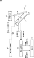
- FIG. 14 is a diagram showing an example of a 3D endoscopic image (a left-eye image or a right-eye image constituting the same) in which the forceps 61 is reflected.
- FIG. 14 two forceps as the forceps 61 inserted into the body cavity are shown on the left and right sides of the 3D endoscopic image with the tissue as the background.
- the left forceps 61 is reflected over a wide range from the front to the back of the surgical site.
- the forceps area where the left forceps 61 is reflected especially the area on the near side, which has a large area, moves greatly, it may cause discomfort to the user observing the 3D endoscopic image. , It may be a burden on the user.
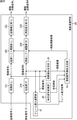
- FIG. 15 is a block diagram illustrating a configuration example of the parallax amount adjustment unit 70 of FIG.
- the parallax amount adjustment unit 70 includes the development units 31L and 31R, the image shift adjustment units 32L and 32R, the image correction units 33L and 33R, and the parallax image generation unit 34 in FIG. Common to the part 12.
- the parallax adjustment unit 70 in FIG. 15 is different from the parallax adjustment unit 12 in FIG. 3 in that a parallax adjustment image generation unit 72 is provided instead of the parallax adjustment image generation unit 35. Further, the parallax amount adjusting unit 70 in FIG. 15 is different from the parallax amount adjusting unit 12 in FIG. 3 in that a forceps region detecting unit 71 is newly provided.
- One of the left eye image (the development signal L) obtained by the developing unit 31L and the right eye image (the development signal R) obtained by the developing unit 31R is supplied to the forceps region detection unit 71.
- the left eye image serving as a reference in generating the parallax image is supplied to the forceps region detection unit 71.
- the forceps region detection unit 71 detects a forceps region in which the forceps 61 is reflected from the left eye image supplied from the developing unit 31L, generates a forceps region image representing the detection result, and supplies the forceps region image to the parallax adjustment image generation unit 72. To do.
- the method of detecting the forceps region by the forceps region detection unit 71 is not particularly limited.
- a method for detecting the forceps region for example, a first detection method or a second detection method can be employed.
- the hue (hue) is calculated from the R, G, and G values of the development signal L of the left eye image. ) Is calculated. Then, by performing the threshold processing of the hue, a region in which the forceps 61 are colored is detected as a forceps region.
- the luminance of each pixel is obtained from the R, G, and G values of the development signal L of the left eye image, and a luminance image having the luminance as the pixel value is generated. Furthermore, by performing edge detection of the luminance image, an edge image representing the edge is generated, and by performing Hough transform of the edge image, a straight line (like edge) on the edge image is detected. Then, two straight lines having a long length are detected from the straight lines on the edge image, and a region surrounded by the two straight lines is detected as a forceps region.
- the parallax adjustment image generation unit 72 is supplied with a parallax image from the parallax image generation unit 34 in addition to being supplied with a forceps region image from the forceps region detection unit 71.
- the parallax adjustment image generation unit 72 generates a parallax adjustment image using the parallax image from the parallax image generation unit 34 based on the forceps region image from the forceps region detection unit 71 and supplies the parallax adjustment image to the image shift adjustment units 32L and 32R. To do.
- the parallax The adjusted image generation unit 72 obtains the parallax adjustment value c (x, y) according to, for example, the equation (10).
- the parallax adjustment image generation unit 72 obtains the parallax adjustment value c (x, y), for example, according to the equation (11).
- the parallax adjustment image generation unit 72 obtains the parallax adjustment value c (x, y) according to the equation (10) or the equation (11), and uses the parallax adjustment value c (x, y) as the pixel value.
- a parallax adjustment image to be generated is generated and supplied to the image shift adjustment units 32L and 32R.
- the threshold value TH3 is a threshold value used for detecting a burden area, and a is a constant of 1 or more.
- the values of TH3 and a are experimentally determined by, for example, an endoscope system developer.
- a region where the parallax d (x, y) is larger than the threshold TH3 in the forceps region in which the forceps 61 as a predetermined object is reflected, that is, the region on the near side is a burden. Detected as a region.
- the burden area for example, the value corresponding to the parallax amount d (x, y) ((d (x, y) ⁇ d (x, y) / a) / a) as in the case of Expression (1).
- the parallax adjustment value c (x, y) of 2) is obtained.
- the parallax adjustment image generation unit 72 even if the pixel at the position (x, y) is not the forceps region, or the pixel at the position (x, y) is the forceps region, the parallax d (x, y ) Is not larger than the threshold value TH3, the parallax adjustment value c (x, y) having a value of 0 is obtained assuming that the pixel at the position (x, y) is not a burden area.
- the near side of the forceps area where the forceps 61 is reflected is adjusted so that the parallax is reduced. As a result, the burden on the user can be reduced.
- FIG. 16 is a diagram illustrating an example of a forceps region image generated by the forceps region detection unit 71 of FIG.
- FIG. 16A shows an example of a left eye image as a target image to be detected by the forceps region in the forceps region detection unit 71.
- FIG. 16A shows an example of a left eye image as a target image to be detected by the forceps region in the forceps region detection unit 71.
- forceps 61 are reflected from the center to the lower part of the left eye image.
- 16B shows an example of a forceps region image generated by detecting a forceps region from the left eye image of FIG. 16A.
- the forceps region image is, for example, a binary image representing the forceps region.
- FIG. 17 is a flowchart for explaining an example of processing for adjusting the amount of parallax of a 3D endoscope image performed in step S2 of FIG. 5 in the endoscope system of FIG.
- step S51 the developing units 31L and 31R perform development processing, and the processing proceeds to step S52.
- the developing unit 31L performs a developing process on the image signal L of the left eye image constituting the 3D endoscopic image from the endoscope 11 to generate the developing signal L, and the image shift adjusting unit. 32L, the parallax image generation unit 34, and the forceps region detection unit 71.
- the developing unit 31R performs a developing process on the image signal R of the right eye image constituting the 3D endoscopic image from the endoscope 11 to generate the developing signal R, and the image shift adjusting unit 32R. And it supplies to the parallax image generation part 34.
- step S52 the parallax image generating unit 34 uses the left eye image from the developing unit 31L and the right eye image from the developing unit 31R to generate a parallax image having the parallax amount d (x, y) as a pixel value.
- the image is generated and supplied to the parallax adjustment image generation unit 72, and the process proceeds to step S53.
- step S53 the forceps region detection unit 71 performs a forceps region detection process for detecting a forceps region from the left eye image from the developing unit 31L, generates a forceps region image representing the forceps region, and a parallax adjustment image generation unit. 72.
- step S53 the process proceeds from step S53 to step S54, and the parallax adjustment image generation unit 72 uses the parallax image supplied from the parallax image generation unit 34 based on the forceps region image from the forceps region detection unit 71 to perform parallax.
- a parallax adjustment image having the adjustment value c (x, y) as a pixel value is generated.
- parallax adjustment image generation unit 72 supplies the parallax adjustment image to the image shift adjustment units 32L and 32R, and the process proceeds from step S54 to step S55.
- steps S55 and S56 the same processes as in steps S14 and S15 of FIG. 6 are performed.
- FIG. 18 is a flowchart illustrating an example of the forceps region detection process performed in step S53 of FIG.
- the forceps region detection unit 71 detects the forceps region from the left eye image by, for example, the second detection method of the first and second detection methods described above.
- step S61 the forceps region detection unit 71 obtains the luminance of each pixel from the R, G, and G values of the development signal L of the left eye image from the development unit 31L, and calculates the luminance as the pixel value. And the process proceeds to step S62.
- step S62 the forceps region detection unit 71 performs edge detection of the luminance image, generates an edge image showing the edge, and the process proceeds to step S63.
- step S63 the forceps region detection unit 71 performs a Hough transform on the edge image to detect a straight line (line segment) on the edge image, and the process proceeds to step S64.
- step S64 the forceps region detection unit 71 detects two straight lines in order of length from the straight lines on the edge image detected in step S63 as boundary straight lines representing the boundaries of the forceps region. The process proceeds to step S65.
- step S65 the forceps region detection unit 71 detects a region surrounded by two boundary straight lines as a forceps region, and the process ends (returns).
- the forceps region (a part of) the forceps 61 is detected as a burden region.
- a sheath And other predetermined objects that are burdensome for the user observing 3D endoscopic images for example, objects that move greatly in the depth direction, or moving objects that occupy a large area in 3D endoscopic images) Etc.
- the amount of parallax can be adjusted so that a user's burden may be reduced.
- the endoscope system of the present embodiment for example, in a case where a surgical operation is performed while observing a 3D endoscope image, intense movement close to the distal end of the endoscope scope 11B is performed. Since the amount of parallax is adjusted with respect to mist and smoke, a 3D endoscopic image with less discomfort and discomfort can be presented to the user (operator).
- the endoscope system of the present embodiment for example, in a case where a surgical operation is performed while observing a 3D endoscope image, the forceps region close to the distal end of the endoscope scope 11B is applied.
- the amount of parallax is adjusted, a 3D endoscopic image with less discomfort and discomfort can be presented to the user.
- the endoscope system of the present embodiment it is possible to reduce user fatigue and contribute to maintenance of concentration.
- the present technology for example, an endoscopic image captured by a so-called capsule endoscope It can be applied when processing.
- the present technology can be applied when processing an image obtained by imaging a living body other than a human body in addition to an image obtained by imaging a human body.
- the present technology can be applied when processing a biological image obtained by imaging the living body with a microscope.
- the present technology can be applied to an endoscope image obtained by imaging a subject other than a living body with an endoscope called a fiberscope.
- the adjustment of the parallax amount in the endoscope system of the first to third embodiments described above can be used in combination. That is, for example, the adjustment to reduce the amount of parallax can be performed in both the area where smoke and mist are reflected and the forceps area where the forceps are reflected.
- a series of processing of the parallax amount adjusting unit 12 and 40 and 70 can be performed by hardware or can be performed by software.
- a program constituting the software is installed in a microcomputer or the like.
- FIG. 19 shows a configuration example of an embodiment of a computer in which a program for executing the series of processes described above is installed.
- the program can be recorded in advance in a hard disk 105 or a ROM 103 as a recording medium built in the computer.
- the program can be stored (recorded) in the removable recording medium 111.
- a removable recording medium 111 can be provided as so-called package software.
- examples of the removable recording medium 111 include a flexible disk, a CD-ROM (Compact Disc Read Only Memory), an MO (Magneto Optical) disc, a DVD (Digital Versatile Disc), a magnetic disc, and a semiconductor memory.
- the program can be installed on the computer from the removable recording medium 111 as described above, or can be downloaded to the computer via the communication network or the broadcast network and installed on the built-in hard disk 105. That is, the program is transferred from a download site to a computer wirelessly via a digital satellite broadcasting artificial satellite, or wired to a computer via a network such as a LAN (Local Area Network) or the Internet. be able to.
- a network such as a LAN (Local Area Network) or the Internet.
- the computer includes a CPU (Central Processing Unit) 102, and an input / output interface 110 is connected to the CPU 102 via the bus 101.
- CPU Central Processing Unit
- the CPU 102 executes a program stored in a ROM (Read Only Memory) 103 accordingly. .
- the CPU 102 loads a program stored in the hard disk 105 into a RAM (Random Access Memory) 104 and executes it.
- the CPU 102 performs processing according to the flowchart described above or processing performed by the configuration of the block diagram described above. Then, the CPU 102 outputs the processing result as necessary, for example, via the input / output interface 110, from the output unit 106, transmitted from the communication unit 108, and further recorded in the hard disk 105.
- the input unit 107 includes a keyboard, a mouse, a microphone, and the like.
- the output unit 106 includes an LCD (Liquid Crystal Display), a speaker, and the like.
- the processing performed by the computer according to the program does not necessarily have to be performed in chronological order in the order described as the flowchart. That is, the processing performed by the computer according to the program includes processing executed in parallel or individually (for example, parallel processing or object processing).
- the program may be processed by one computer (processor), or may be distributedly processed by a plurality of computers. Furthermore, the program may be transferred to a remote computer and executed.
- the system means a set of a plurality of components (devices, modules (parts), etc.), and it does not matter whether all the components are in the same housing. Accordingly, a plurality of devices housed in separate housings and connected via a network and a single device housing a plurality of modules in one housing are all systems. .
- the present technology can take a cloud computing configuration in which one function is shared by a plurality of devices via a network and is jointly processed.
- each step described in the above flowchart can be executed by one device or can be shared by a plurality of devices.
- the plurality of processes included in the one step can be executed by being shared by a plurality of apparatuses in addition to being executed by one apparatus.
- this technique can take the following structures.
- An image processing apparatus comprising: a parallax amount adjustment unit that adjusts a parallax amount of a 3D biological image according to whether or not a parallax of a 3D (Dimensions) biological image obtained by imaging a biological body is a burden on a user.
- a parallax amount adjustment unit that adjusts a parallax amount of a 3D biological image according to whether or not a parallax of a 3D (Dimensions) biological image obtained by imaging a biological body is a burden on a user.
- the parallax amount adjustment unit adjusts the parallax amount of the 3D biological image when an energy device is used.
- the energy device is an electric knife.
- ⁇ 4> The image processing device according to ⁇ 1>, wherein the parallax amount adjustment unit adjusts a parallax amount of a burden area where a parallax in the 3D biological image is a burden based on the 3D biological image.
- ⁇ 5> The image processing device according to ⁇ 4>, wherein the parallax amount adjustment unit adjusts the parallax amount of the burden area based on the movement of the 3D biological image.
- ⁇ 6> The image processing device according to ⁇ 4>, wherein the parallax amount adjustment unit adjusts the parallax amount of the burden area based on luminance of the 3D biological image.
- ⁇ 7> The image processing device according to ⁇ 4>, wherein the parallax amount adjustment unit adjusts the parallax amount of the burden area based on a motion and luminance of the 3D biological image.
- the parallax adjustment unit detects an area in which a predetermined object appears in the 3D biological image as the burden area.
- the parallax adjustment unit detects a region where a treatment tool is reflected in the 3D biological image as the burden region.
- ⁇ 10> The image processing apparatus according to ⁇ 8>, wherein the parallax adjustment unit detects a region where mist or smoke appears in the 3D biological image as the burden region.
- the parallax amount adjustment unit adjusts the parallax amount of the 3D biological image so that the parallax is reduced.
- the parallax amount adjustment unit adjusts the parallax amount of the 3D biological image so that the parallax is reduced by an adjustment value corresponding to the parallax amount.
- the parallax amount adjustment unit reduces the parallax amount of the 3D biological image by an adjustment value corresponding to the parallax amount and one or both of the motion and luminance of the 3D biological image.
- the image processing apparatus according to ⁇ 11>.
- the parallax amount adjusting unit includes a pixel value of a target pixel of one of a left eye image observed with a left eye and a right eye image observed with a right eye constituting the 3D biological image, and The parallax amount of the 3D biological image is adjusted by horizontally shifting the pixel value of the corresponding pixel corresponding to the target pixel of the other of the left eye image and the right eye image.
- the image processing device according to any one of ⁇ 1> to ⁇ 13>.
- An image correction unit that corrects the left eye image and the right eye image by interpolating a pixel value of a missing pixel in which a pixel value is missing due to the shift of the pixel value of the left eye image and the right eye image.
- the image processing apparatus according to ⁇ 14>.
- ⁇ 16> The image processing device wherein the image correction unit interpolates a pixel value of the missing pixel by a pixel value of a pixel that is not a missing pixel among pixels in the vicinity of the missing pixel.
- ⁇ 17> The image processing apparatus according to any one of ⁇ 1> to ⁇ 16>, wherein the biological image is an endoscopic image obtained by imaging the living body with an endoscope.
- An image processing method including a step of adjusting a parallax amount of a 3D biological image according to whether or not a parallax of a 3D (Dimensions) biological image obtained by imaging a biological body is a burden on a user.
- An endoscope that captures 3D (Dimensions) images;
- a parallax amount adjustment unit that adjusts the parallax amount of the 3D biological image according to whether or not the parallax of the 3D biological image obtained by imaging the living body with the endoscope is a burden on the user;
- An endoscope system comprising: a display unit that displays the 3D biological image in which the parallax amount is adjusted by the parallax amount adjusting unit.
Abstract
本技術は、ユーザの負担を軽減することができるようにする画像処理装置、画像処理方法、プログラム、及び、内視鏡システムに関する。 視差量調整部において、生体を撮像した3D(Dimensions)の生体画像の視差がユーザにとって負担になるかどうかに応じて、3Dの生体画像の視差量が調整される。本技術は、例えば、内視鏡で生体を撮像する内視鏡システム等に適用することができる。
Description
本技術は、画像処理装置、画像処理方法、プログラム、及び、内視鏡システムに関し、特に、例えば、ユーザの負担を軽減することができるようにする画像処理装置、画像処理方法、プログラム、及び、内視鏡システムに関する。
例えば、内視鏡システムについては、内視鏡を用いた手術や診断等の処置において、処置具を奥行き方向にスムースに誘導するために、人体(内部)を、3D(Dimensions)の画像で撮像し、その結果得られる3Dの内視鏡画像を表示することが要請されている(例えば、特許文献1を参照)。
3Dの内視鏡画像によれば、ユーザは、その3Dの内視鏡画像を観察することにより、奥行き方向の情報を得ることができ、そのため、例えば、処置具を、奥行き方向にスムースに誘導することができる。
ところで、3Dの内視鏡画像は、例えば、ユーザの左眼で観察される左眼画像とユーザの右眼で観察される右眼画像とで構成される。そして、3Dの内視鏡画像を構成する左眼画像と右眼画像とには、視差があり、この視差があることによって、3Dの内視鏡画像を観察するユーザは、奥行き方向の情報を知覚する。
以上のように、3Dの内視鏡画像を観察するユーザは、その3Dの内視鏡画像の視差によって、奥行き方向の情報を知覚することができるが、かかる3Dの内視鏡画像を観察するにあたって、ユーザは、3Dに特有の違和感や不快感を感じる場合があり、ユーザの負担になることがある。
すなわち、3Dの内視鏡画像において、例えば、動きが激しい物体が映っている場合や、手前から奥に亘っている物体の手前側の部分が動く場合には、3Dの内視鏡画像を観察しているユーザが、負担を感じることがある。
本技術は、このような状況に鑑みてなされたものであり、ユーザの負担を軽減することができるようにするものである。
本技術の画像処理装置、又は、プログラムは、生体を撮像した3D(Dimensions)の生体画像の視差がユーザにとって負担になるかどうかに応じて、前記3Dの生体画像の視差量を調整する視差量調整部を備える画像処理装置、又は、そのような画像処理装置として、コンピュータを機能させるためのプログラムである。
本技術の画像処理方法は、生体を撮像した3D(Dimensions)の生体画像の視差がユーザにとって負担になるかどうかに応じて、前記3Dの生体画像の視差量を調整するステップを含む画像処理方法である。
本技術の内視鏡システムは、3D(Dimensions)の画像を撮像する内視鏡と、前記内視鏡で生体を撮像することにより得られる3Dの生体画像の視差がユーザにとって負担になるかどうかに応じて、前記3Dの生体画像の視差量を調整する視差量調整部と、前記視差量調整部で前記視差量が調整された前記3Dの生体画像を表示する表示部とを備える内視鏡システムである。
本技術の画像処理装置、画像処理方法、プログラム、及び、内視鏡システムにおいては、生体を撮像した3D(Dimensions)の生体画像の視差がユーザにとって負担になるかどうかに応じて、前記3Dの生体画像の視差量が調整される。
なお、画像処理装置は、独立した装置であっても良いし、1つの装置を構成している内部ブロックであっても良い。
また、プログラムは、伝送媒体を介して伝送することにより、又は、記録媒体に記録して、提供することができる。
本技術によれば、ユーザの負担を軽減することができる。
なお、ここに記載された効果は必ずしも限定されるものではなく、本開示中に記載されたいずれかの効果であってもよい。
<内視鏡システムの第1実施の形態>
図1は、本技術を適用した内視鏡システムの第1実施の形態の構成例を示すブロック図である。
図1において、内視鏡システムは、内視鏡11、視差量調整部12、表示部13、電気メス14、電気メススイッチ15、及び、電気メス制御部16を有する。
内視鏡11は、例えば、患者(人体)の体腔に挿入され、その体腔内の組織を被写体とする3Dの画像である内視鏡画像を撮像する。
すなわち、内視鏡11は、例えば、外観上、内視鏡システムのユーザとしての手術等を行う術者(医師)が手で持つカメラヘッド11Aと、患者の体内に挿入される内視鏡スコープ11Bとを有する。
内視鏡下手術、つまり、内視鏡システムを用いた手術では、内視鏡スコープ11Bが体内に挿入され、ユーザが、カメラヘッド11Aを持って、内視鏡11を操作する。
内視鏡11では、例えば、内視鏡スコープ11Bの先端から、光が照射され、その光によって、患者の体内の被写体となる術部(組織)が照明される。被写体を照明する光は、被写体で反射され、その被写体からの反射光が、内視鏡スコープ11Bの先端から入射する。そして、内視鏡11では、内視鏡スコープ11Bの先端から入射した光が受光され、光電変換されることにより、被写体の3Dの内視鏡画像が撮像される。
ここで、内視鏡11で撮像された3Dの内視鏡画像は、左眼で観察される左眼画像の画像信号Lと、右眼で観察される右眼画像の画像信号Rとで構成される。左眼画像と右眼画像とには、視差があり、ユーザは、かかる視差がある左眼画像及び右眼画像を、左眼及び右眼でそれぞれ観察することにより、奥行き方向の情報を知覚することができる。
内視鏡11で撮像された3Dの内視鏡画像を構成する左眼画像の画像信号L、及び、右眼画像の画像信号Rは、視差量調整部12に供給される。
視差量調整部12は、内視鏡画像11からの3Dの内視鏡画像(の画像信号L及びR)の視差が、その内視鏡画像を観察するユーザにとって負担になるかどうかに応じて、内視鏡画像11からの3Dの内視鏡画像の視差量を、ユーザの負担が軽減されるように調整する。
すなわち、図1において、視差量調整部12は、例えば、後述するように、電気メス制御部16から供給される電気メス制御情報に基づいて、内視鏡画像11からの3Dの内視鏡画像の視差がユーザにとって負担になるかどうかを検出(判定)する。そして、内視鏡画像11からの3Dの内視鏡画像の視差がユーザにとって負担になる場合には、視差量調整部12は、内視鏡画像11からの3Dの内視鏡画像の視差量を、視差が小さくなるように調整する。
視差量調整部12は、視差量を調整した後の3Dの内視鏡画像を構成する左眼画像の画像信号L(以下、調整画像信号Lともいう)、及び、右眼画像の画像信号R(以下、調整画像信号Rともいう)を、表示部13に供給する。
表示部13は、3Dの画像を表示することが可能な、例えば、ヘッドマウントディスプレイ等の表示デバイスであり、視差量調整部12から供給される3Dの内視鏡画像を表示する。
なお、3Dの内視鏡画像を構成する左眼画像の(調整)画像信号L及び(調整)右眼画像の画像信号Rの表示方式としては、例えば、サイドバイサイド方式や、ラインバイライン方式、フレームシーケンシャル方式等がある。表示部13において、3Dの画像を表示する表示方式は、特に限定されるものではない。
電気メス14は、電気メス制御部16から供給される高周波の電流を人体に流すことで、人体の組織を切開する施術を施すことができる処置具である。
ここで、本明細書では、内視鏡システムを用いた手術や診断等において、何らかの処置を施すのに用いられる道具を、処置具といい、処置具の中で、特に、手術に用いられる道具を、術具という。電気メス14は、エネルギデバイスと呼ばれる術具の1つである。エネルギデバイスとしては、電気メス14のように、電流を用いるデバイスの他、例えば、超音波を用いるデバイス等がある。
電気メススイッチ15は、電気メス14に流す電流をオン又はオフにするときに、例えば、ユーザによって操作される。電気メススイッチ15は、電流をオン又はオフにするように操作されると、その操作に対応する電気メス制御信号を、電気メス制御部16に供給する。
電気メス制御部16は、電気メススイッチ15から供給される電気メス制御信号に応じて、電気メス14への高周波の電流の供給を、オン又はオフにする。また、電気メス制御部16は、電気メス制御信号に応じて、電気メス14がオン又はオフになっていることを表す電気メス制御情報を、視差量調整部12に供給する。
以上のように構成される内視鏡システムでは、ユーザ(術者)が、内視鏡スコープ11Bを、患者の体内に挿入し、内視鏡11において、患者の体内の被写体となる術部(組織)の3Dの内視鏡画像が撮像される。
内視鏡11で撮像された3Dの内視鏡画像(を構成する左眼画像の画像信号L、及び、右眼画像の画像信号R)は、内視鏡11から視差量調整部12に供給され、さらに、視差量調整部12から表示部13に供給されて表示される。
ユーザが、表示部13に表示された3Dの内視鏡画像を見ながら、手術を実施するために、電気メススイッチ15をオンにするように操作すると、オンを表す電気メス制御信号が、電気メス制御部16に供給される。
電気メス制御部16は、電気メススイッチ15からのオンを表す電気メス制御信号に応じて、電気メス14への高周波の電流の供給をオンにし(開始し)、これにより、ユーザは、電気メス14によって、患者の組織を切開することが可能になる。
また、電気メス制御部16は、電気メス14のオン又はオフを表す電気メス制御情報を、視差量調整部12に供給する。
電気メス制御情報が、電気メス14のオンを表しており、したがって、電気メス14が使用されている場合、視差量調整部12は、表示部13に表示された3Dの内視鏡画像の視差がユーザの負担になる場合であるとして、内視鏡11からの3Dの内視鏡画像の視差量を調整する。
すなわち、電気メス14が使用されている場合には、その電気メス14を用いて、人体の組織が切開されるときに、ミストや煙が生じる。この、電気メス14の使用時に生じるミストや煙が激しく動き、内視鏡スコープ11Bの先端に近接して、3Dの内視鏡画像に映ると、その3Dの内視鏡画像を観察しているユーザは、動きの激しいミストや煙に不快感を感じることがある。
3Dの内視鏡画像に映る動きの激しいミストや煙によって生じるユーザの不快感は、3Dの内視鏡画像を観察するユーザの負担を大きくし、ユーザが、本来見たい部分を注視することの妨げとなる。
そこで、電気メス14が使用されている場合には、その電気メス14の使用によって生じるミストや煙が3Dの内視鏡画像に映ることによるユーザの負担を軽減すべく、視差量調整部12は、内視鏡11からの3Dの内視鏡画像の視差量を、視差が小さくなるように調整する。
そして、表示部13では、視差量調整部12において視差量が調整された3Dの内視鏡画像が表示される。
なお、図1では、エネルギデバイスとして、電気メス14を採用しているが、エネルギデバイスとしては、電気メス14の他、例えば、超音波を用いるデバイス等の、電気メス14以外のエネルギデバイスを採用することができる。
図2は、3Dの内視鏡画像を撮像する内視鏡11の模式的な構成例を示す図である。
内視鏡11は、2個の撮像素子(イメージセンサ)21L及び21Rを有する。
撮像素子21Lは、左眼画像となる画像を撮像する。撮像素子21Rは、右眼画像となる画像を撮像する。
図2において、撮像素子21L及び21Rは、水平(左右)方向に並べて配置されており、これにより、撮像素子21L及び21Rでは、視差がある左眼画像及び右眼画像がそれぞれ撮像される。
なお、内視鏡11において、撮像素子21L及び21Rは、例えば、内視鏡スコープ11Bの先端部分や、カメラヘッド11Aに設けることができる。
また、3Dの画像を撮像する方法としては、例えば、いわゆる2眼で撮像を行う方法や、1眼(単眼)で撮像を行う方法があるが、内視鏡11において、3Dの内視鏡画像を撮像する方法は、特に限定されるものではない。
図3は、図1の視差量調整部12の構成例を示すブロック図である。
図3において、視差量調整部12は、現像部31L及び31R、画像シフト調整部32L及び32R、画像補正部33L及び33R、視差画像生成部34、並びに、視差調整画像生成部35を有する。
現像部31Lには、内視鏡11から、3Dの内視鏡画像を構成する左眼画像の画像信号Lが供給される。
ここで、内視鏡11で撮像される3Dの内視鏡画像を構成する左眼画像及び右眼画像は、例えば、ベイヤ配列等の所定の配列の、いわゆるRAW画像になっている。
現像部31Lは、内視鏡11からの左眼画像の画像信号Lを対象に、現像処理を行って、R(red),G(green)、及び、B(blue)の各プレーンの画像信号を有する現像信号Lを生成し、画像シフト調整部32L、及び、視差画像生成部34に供給する。
画像シフト調整部32Lには、現像部31Lから左眼画像の現像信号Lが供給される他、視差調整画像生成部35から、後述する視差調整画像が供給される。
画像シフト調整部32Lは、現像部31Lからの左眼画像(の現像信号L)の画素の画素値を、視差調整画像生成部35からの視差調整画像に従って、水平方向にシフトすることにより、現像部31Lからの左眼画像で構成される3Dの内視鏡画像の視差量を調整する。
画像シフト調整部32Lは、画素値のシフト後の左眼画像(の画像信号)を、画像補正部33Lに供給する。
画像補正部33Lは、画像シフト調整部32Lからの、画素値のシフト後の左眼画像を構成する画素のうちの欠落画素を補間することにより、左眼画像を補正する。
ここで、画像シフト調整部32Lから画像補正部33Lに供給される、画素値のシフト後の左眼画像を構成する画素の中には、画素値が欠落している欠落画素が存在することがある。
すなわち、後述する視差画像生成部34での視差量の誤検出や、画像シフト調整部32Lでの画素値のシフトにおけるシフト先の重複、シフト先にならなかった画素の存在等に起因して、画素値のシフト後の左眼画像には(右眼画像についても同様)、画素値が欠落している欠落画素が存在することがある。
画像補正部33Lは、左眼画像の欠落画素の画素値を、その欠落画素の近傍の画素であって、欠落画素ではない画素の画素値を用いて補間することで、左眼画像を補正する。そして、画像補正部33Lは、補正後の左眼画像の画像信号、すなわち、視差量が調整された3Dの内視鏡画像を構成する、欠落画素がない左眼画像の画像信号を、調整画像信号Lとして、表示部13に供給する。
現像部31Rには、内視鏡11から、3Dの内視鏡画像を構成する右眼画像の画像信号Rが供給される。
現像部31R、画像シフト調整部32R、及び、画像補正部33Rは、現像部31L、画像シフト調整部32L、及び、画像補正部33Lとそれぞれ同様の処理を行う。
すなわち、現像部31Rは、内視鏡11からの右眼画像の画像信号Rを対象に、現像処理を行って、R,G、及び、Bの各プレーンの画像信号を有する現像信号Rを生成し、画像シフト調整部32R、及び、視差画像生成部34に供給する。
画像シフト調整部32Rは、現像部31Rからの右眼画像(の現像信号R)の画素の画素値を、視差調整画像生成部35からの視差調整画像に従って、水平方向にシフトすることにより、現像部31Rからの右眼画像で構成される3Dの内視鏡画像の視差量を調整する。
画像シフト調整部32Rは、画素値のシフト後の右眼画像(の画像信号)を、画像補正部33Rに供給する。
画像補正部33Rは、画素値補正部33Lと同様に、画像シフト調整部32Rからの、画素値のシフト後の右眼画像を構成する画素のうちの欠落画素を補間することにより、右眼画像を補正する。画像補正部33Rは、右眼画像の補正により得られる、視差量が調整された3Dの内視鏡画像を構成する、欠落画素がない右眼画像の画像信号を、調整画像信号Rとして、表示部13に供給する。
視差画像生成部34は、現像部31Lから供給される左眼画像(の現像信号L)と、現像部31Rから供給される右眼画像(の現像信号R)とを用いて、それらの左眼画像と右眼画像との視差量を検出する。
すなわち、視差画像生成部34は、現像部31Lからの左眼画像、及び、現像部31Rからの右眼画像のうちの一方の画像である、例えば、左眼画像を基準として、その左眼画像の各画素について、右眼画像において対応する対応画素を検出する。
具体的には、視差画像生成部34は、例えば、左眼画像の各画素を、順次、注目する注目画素に選択し、右眼画像の画素から、注目画素に対応する対応画素を検出する。
対応画素は、例えば、右眼画像において、注目画素を含むブロックと類似するブロックを水平方向に探索するブロックマッチング等を行うことによって検出することができる。
視差画像生成部34は、右眼画像において、注目画素に対応する位置からの、対応画素の位置のずれ量を、注目画素と対応画素との視差量として検出し、その視差量を画素値とする視差画像を生成する。
すなわち、視差画像生成部34は、注目画素に対して検出された視差量を、注目画素の位置の画素の画素値とする画像を、視差画像として生成する。
視差画像生成部34は、視差画像を生成すると、その視差画像を、視差調整画像生成部35に供給する。
視差調整画像生成部35は、視差画像生成部34からの視差画像を用いて、その視差画像の画素値になっている視差量を調整する視差調整値を画素値とする視差調整画像を生成する。
すなわち、視差量調整画像生成部35には、視差画像生成部34から視差画像が供給される他、電気メス制御部16から、電気メス制御情報が供給される。
視差量調整画像生成部35は、電気メス制御情報に基づき、視差画像生成部34からの視差画像を用いて、視差調整画像を生成する。
具体的には、いま、視差画像の位置(x,y)の画素の画素値である視差量を、d(x,y)と表すとともに、視差調整画像の位置(x,y)の画素の画素値である視差調整値を、c(x,y)と表すこととする。
視差調整画像生成部35は、例えば、式(1)又は式(2)に従って、視差量d(x,y)を調整する視差調整値c(x,y)を求める。
c(x,y)=(d(x,y)-d(x,y)/a)/2
・・・(1)
c(x,y)=0
・・・(2)
・・・(1)
c(x,y)=0
・・・(2)
なお、式(1)において、aは、1以上の定数であり、例えば、内視鏡システムの開発者によって、実験的に値が決定される。
また、視差調整値c(x,y)を、式(1)及び式(2)のうちのいずれに従って求めるかは、電気メス制御情報に基づいて制御される。
すなわち、電気メス制御情報が、電気メス14のオンを表している場合には、視差調整値c(x,y)は、式(1)に従って求められる。また、電気メス制御情報が、電気メス14のオフを表している場合には、視差調整値c(x,y)は、式(2)に従って求められる。
ここで、式(1)によれば、視差調整値c(x,y)として、視差量d(x,y)に対応する値((d(x,y)-d(x,y)/a)/2)が求められる。また、式(2)によれば、視差調整値c(x,y)として、0が求められる。
したがって、電気メス14がオンになっており、その電気メス14の使用によって、ミストや煙が生じやすい場合には、式(1)に従い、視差量d(x,y)に対応する値の視差調整値c(x,y)が求められる。
また、電気メス14がオフになっており、その電気メス14の使用に起因するミストや煙の発生がない場合には、式(2)に従い、値が0の視差調整値c(x,y)が求められる。
視差調整画像生成部35は、以上のような視差調整値c(x,y)を画素値とする視差調整画像を生成し、画像シフト調整部32L及び32Rに供給する。
画像シフト調整部32L及び32Rでは、以上のようにして視差調整画像生成部35から供給される視差調整画像に従い、左眼画像及び右眼画像の画素の画素値を水平方向にシフトすることにより、その左眼画像及び右眼画像で構成される3Dの内視鏡画像の視差量が調整される。
図4は、画像シフト調整部32L及び32Rでの画素値のシフトによる視差量の調整を説明する図である。
いま、左眼画像の現像信号Lの位置(x,y)の画素を注目画素として、その注目画素の画素値を、l(x,y)と表すとともに、右眼画像の現像信号Rの、注目画素に対応する対応画素の画素値を、r(x,y)と表すこととする。
画像シフト調整部32Lは、左眼画像の現像信号Lの注目画素の画素値l(x,y)を、視差調整画像の位置(x,y)の画素の画素値である視差調整値c(x,y)に従って、水平方向にシフトすることにより、注目画素と対応画素との視差量を調整する。
すなわち、画像シフト調整部32Lは、例えば、式(3)に従い、注目画素の画素値l(x,y)を、-c(x,y)だけ水平方向にシフトした位置の画素値l'(x-c(x,y),y)とする。
l'(x-c(x,y),y)=l(x,y)
・・・(3)
・・・(3)
同様に、画像シフト調整部32Rは、右眼画像の現像信号Rの対応画素の画素値r(x,y)を、視差調整画像の位置(x,y)の画素の画素値である視差調整値c(x,y)に従って、水平方向にシフトすることにより、注目画素と対応画素との視差量を調整する。
すなわち、画像シフト調整部32Rは、例えば、式(4)に従い、対応画素の画素値r(x,y)を、+c(x,y)だけ水平方向にシフトした位置の画素値r'(x+c(x,y),y)とする。
r'(x+c(x,y),y)=r(x,y)
・・・(4)
・・・(4)
視差調整値c(x,y)が0より大である場合には、シフト後の画素値l'(x-c(x,y),y)とr'(x+c(x,y),y)との間の視差は、シフト前の画素値l(x,y)とr(x,y)との間の視差よりも小さくなり、したがって、視差によって感じるユーザの負担を軽減することができる。
画像シフト調整部32L及び32Rでは、左眼画像の現像信号Lの各画素を、順次、注目画素として、左眼画像の現像信号L及び右眼画像の現像信号Rの各画素の画素値をシフトする。
そして、画像シフト調整部32Lは、左眼画像の現像信号Lの各画素の画素値のシフトによって得られる画像の信号を、左眼画像の調整現像信号Lとして、画像補正部33Lに供給する。同様に、画像シフト調整部32Rは、右眼画像の現像信号Rの各画素の画素値のシフトによって得られる画像の信号を、右眼画像の調整現像信号Rとして、画像補正部33Rに供給する。
ここで、図3で説明したように、電気メス14がオフの場合には、視差調整値c(x,y)は、式(2)に従って0になるので、画像シフト調整部32L及び32Rにおいて、画素値のシフトによる視差量の調整は、実質的に行われない。
一方、電気メス14がオンの場合には、視差調整値c(x,y)は、式(1)に従って求められ、画像シフト調整部32L及び32Rにおいて、その視差調整値c(x,y)に従って、画素値のシフトが行われることにより、視差が小さくなるように、視差量が調整される。
オンになっている電気メス14が、人体(被術者(患者))の組織に接触すると、ミストや煙が発生する。このミストや煙が激しく動き、内視鏡スコープ11Bの先端に近接して、3Dの内視鏡画像に映ると、その3Dの内視鏡画像を観察しているユーザは、動きの激しいミストや煙に、3Dの画像に特有の不快感を感じることがある。
3Dの内視鏡画像に映る動きの激しいミストや煙によって生じるユーザの不快感は、3Dの内視鏡画像を観察するユーザの負担を大きくし、ユーザが、本来見たい部分を注視することの妨げとなる。
図1の内視鏡システムでは、電気メス14がオンの場合に、上述したように、視差が小さくなるように、3Dの内視鏡画像の視差量が調整されるので、3Dの内視鏡画像を観察するユーザの負担を軽減することができる。
図5は、図1の内視鏡システムにおいて、3Dの内視鏡画像を表示する画像表示の処理の例を説明するフローチャートである。
ステップS1において、内視鏡11は、例えば、患者(人体)の体腔に挿入され、その体腔内の組織を被写体とする3Dの内視鏡画像を撮像し、その3Dの内視鏡画像を構成する左眼画像の画像信号Lと右眼画像の画像信号Rとを、視差量調整部12に供給する。
そして、処理は、ステップS1からステップS2に進み、視差量調整部12は、内視鏡画像11からの3Dの内視鏡画像(の画像信号L及びR)の視差量を調整し、その視差量の調整後の3Dの内視鏡画像(の調整画像信号L及びR)を、表示部13に供給する。
すなわち、視差量調整部12は、内視鏡画像11からの3Dの内視鏡画像の視差が、その内視鏡画像を観察するユーザにとって負担になる場合に、その3Dの内視鏡画像の視差量を、視差が小さくなるように調整する。そして、視差量調整部12は、視差量の調整後の3Dの内視鏡画像を、表示部13に供給して、処理は、ステップS2からステップS3に進む。
ステップS3では、表示部13は、視差量調整部12から供給される3Dの内視鏡画像を表示する。その後、処理は、ステップS3からステップS1に戻り、以下、同様の処理が繰り返される。
図6は、図1の内視鏡システムにおいて、図5のステップS2で行われる、3Dの内視鏡画像の視差量の調整の処理の例を説明するフローチャートである。
ステップS11において、現像部31L及び31Rは、現像処理を行って、処理は、ステップS12に進む。
すなわち、現像部31Lは、内視鏡11からの3Dの内視鏡画像を構成する左眼画像の画像信号Lを対象に、現像処理を行って、現像信号Lを生成し、画像シフト調整部32L、及び、視差画像生成部34に供給する。
現像部31Rは、内視鏡11からの3Dの内視鏡画像を構成する右眼画像の画像信号Rを対象に、現像処理を行って、現像信号Rを生成し、画像シフト調整部32R、及び、視差画像生成部34に供給する。
ステップS12では、視差画像生成部34は、現像部31Lからの左眼画像、及び、現像部31Rからの右眼画像を用いて、視差量d(x,y)を画素値とする視差画像を生成し、視差調整画像生成部35に供給して、処理は、ステップS13に進む。
ステップS13では、視差調整画像生成部35は、電気メス制御部16から供給される電気メス制御情報に基づき、視差画像生成部34から供給される視差画像を用いて、視差調整値c(x,y)を画素値とする視差調整画像を生成する。
そして、視差調整画像生成部35は、視差調整画像を、画像シフト調整部32L及び32Rに供給して、処理は、ステップS14に進む。
ステップS14では、画像シフト調整部32L及び32Rは、視差調整画像生成部35からの視差調整画像に従い、現像部31Lからの左眼画像、及び、現像部31Rからの右眼画像の各画素の画素値を水平方向にシフトすることにより、その左眼画像及び右眼画像で構成される3Dの内視鏡画像の視差量を調整する。
そして、画像シフト調整部32Lは、画素値のシフト後の左眼画像(の調整画像信号L)を、画像補正部33Lに供給する。さらに、画像シフト調整部32Rは、画素値のシフト後の右眼画像(の調整画像信号R)を、画像補正部33Lに供給し、処理は、ステップS14からステップS15に進む。
ステップS15では、画像補正部33Lは、画像シフト調整部32Lからの、画素値のシフト後の左眼画像を構成する画素のうちの欠落画素を補間することにより、左眼画像を補正する。そして、画像補正部33Lは、左眼画像の補正によって得られる、欠落画素がない左眼画像(の調整画像信号L)を、表示部13に供給する。
さらに、ステップS15では、画像補正部33Rは、画像シフト調整部32Rからの、画素値のシフト後の右眼画像を構成する画素のうちの欠落画素を補間することにより、右眼画像を補正する。そして、画像補正部33Rは、右眼画像の補正によって得られる、欠落画素がない右眼画像(の調整画像信号R)を、表示部13に供給し、処理は終了する(リターンする)。
図7は、画像補正部33L及び33Rでの欠落画素(の画素値)の補間の例を説明する図である。
画像補正部33Lは、左眼画像を構成する画素を、順次、注目画素とする。そして、注目画素が、画像シフト調整部32Lでの画素値のシフトによって画素値が欠落している欠落画素である場合には、その欠落画素となっている注目画素の画素値を補間する。
欠落画素となっている注目画素の画素値の補間は、例えば、注目画素の近傍の画素のうちの、欠落画素になっていない画素の画素値を用いて行われる。
すなわち、画像補正部33Lは、例えば、図7に示すように、左眼画像において、注目画素に隣接する8画素のうちの、欠落画素になっていない画素の画素値の平均値を、欠落画素となっている注目画素の画素値として求める。
図7では、欠落画素になっている注目画素に隣接する8画素のうちの、注目画素の右に隣接する右隣接画素と、注目画素の下に隣接する下隣接画素とが、欠落画素になっている。この場合、欠落画素になっている注目画素に隣接する8画素のうちの、右隣接画素及び下隣接画素を除く6画素の画素値a,b,c,d,e,fの平均値(a+b+c+d+e+f)/6によって、欠落画素になっている注目画素の画素値が補間される。
画像補正部33Rでも、画像補正部33Lと同様に、右眼画像の欠落画素の補間が行われる。
図8は、図6のステップS15で行われる、欠落画素の補間による左眼画像及び右眼画像の補正の処理の例を説明するフローチャートである。
ステップS21において、画像補正部33Lは、補間を行った画素(欠落画素)をカウントする変数としての画素カウントと、左眼画像において、注目画素とする画素の位置を表す変数としての注目画素位置とをリセットし、処理は、ステップS22に進む。
すなわち、画素カウントのリセットでは、例えば、画素カウントが0に設定される。注目画素位置のリセットでは、例えば、注目画素位置が、左眼画像の最も左上の画素の位置から、1画素分だけ左の位置に設定される。
ステップS22では、画像補正部33Lは、注目画素位置を、例えば、ラスタスキャン順に、1画素分だけ更新し、処理は、ステップS23に進む。
ステップS23では、画像補正部33Lは、左眼画像の画素のうちの、注目画素位置の画素、すなわち、注目画素が、欠落画素であるかどうかを判定する。
ステップS23において、注目画素が、欠落画素でないと判定された場合、処理は、ステップS24及びS25をスキップして、ステップS26に進む。
また、ステップS23において、注目画素が、欠落画素であると判定された場合、処理は、ステップS24に進む。
ステップS24では、画像補正部33Lは、左眼画像の画素の中で、注目画素の近傍(周辺)にある画素のうちの、欠落画素でない画素の画素値を用いて、欠落画素になっている注目画素の画素値を補間し、処理は、ステップS25に進む。
ステップS25では、画像補正部33Lは、ステップS24で補間を行った画素をカウントする変数としての補間画素数を、1だけインクリメントし、処理は、ステップS26に進む。
ステップS26では、画像補正部33Lは、左眼画像を構成するすべての画素を、注目画素として、注目画素が欠落画素かどうかの判定を行ったかどうかを判定する。
ステップS26において、左眼画像を構成するすべての画素を、まだ、注目画素としていないと判定された場合、処理は、ステップS22に戻り、以下、同様の処理が繰り返される。
また、ステップS26において、左眼画像を構成するすべての画素を、注目画素としたと判定された場合、すなわち、注目画素位置が、左眼画像のラスタスキャン順で最後の画素の位置になっている場合、処理は、ステップS27に進み、画像補正部33Lは、画素カウントが0であるかどうかを判定する。
ステップS27において、画素カウントが0でないと判定された場合、処理は、ステップS21に戻り、以下、同様の処理が繰り返される。
すなわち、直前のステップS22ないしS26のループ処理において、左眼画像に欠落画素が存在し、その欠落画素の画素値の補間が行われた場合、左眼画像に、まだ、欠落画素が存在する可能性があるため、ステップS21ないしS27の処理が、リカーシブに繰り返される。
一方、ステップS27において、画素カウントが0であると判定された場合、処理は終了する(リターンする)。
すなわち、直前のステップS22ないしS26のループ処理において、左眼画像に欠落画素が存在しないことが確認された場合、画像補正部33Lは、ステップS24の画素値の補間によって得られた左眼画像を、表示部13に供給し、処理は終了する。
ここで、画像補正部33Lにおいて、注目画素が欠落画素であるかどうかの判定は、例えば、欠落画素を表す欠落フラグを用いて行うことができる。
すなわち、画像シフト調整部32Lにおいて、シフト後の画素値を格納するメモリに、欠落フラグを埋め込んでおき(記憶させておき)、そのメモリに、シフト後の画素値を、上書きの形で書き込ませる。
この場合、シフト後の画素値が書き込まれなかったメモリアドレスには、欠落フラグが記憶されたままになっているので、欠落フラグが記憶されたメモリアドレスに対応する画素が、欠落画素であると判定することができる。
なお、画像補正部33Rでは、画像補正部33Lと同様に、右眼画像の補正が行われる。
<内視鏡システムの第2実施の形態>
図9は、本技術を適用した内視鏡システムの第2実施の形態の構成例を示すブロック図である。
なお、図中、図1の場合と対応する部分については、同一の符号を付してあり、以下では、その説明は、適宜、省略する。
図9において、内視鏡システムは、内視鏡11、表示部13、電気メス14、電気メススイッチ15、及び、電気メス制御部16を有する点で、図1の場合と共通する。
但し、図9の内視鏡システムは、視差量調整部12に代えて、視差量調整部40が設けられている点で、図1の場合と相違する。
視差量調整部40は、内視鏡画像11からの3Dの内視鏡画像の視差が、その内視鏡画像を観察するユーザにとって負担になる場合に、3Dの内視鏡画像の視差量を、ユーザの負担が軽減されるように調整し、その調整後の内視鏡画像を表示部13に供給する点で、図1の視差量調整部12と共通する。
但し、視差量調整部40は、内視鏡画像11からの3Dの内視鏡画像に基づいて、その3Dの内視鏡画像における視差が負担になる負担領域の視差量を調整する点で、電気メス制御情報に基づいて視差量を調整する視差量調整部12と相違する。
そのため、図9の内視鏡システムでは、図1の場合のように、電気メス制御部16から視差量調整部40には、電気メス制御情報が供給されるようにはなっていない。
但し、図9の内視鏡システムでは、図1の場合と同様に、電気メス制御部16から視差量調整部40に、電気メス制御情報を供給することができる。この場合、視差量調整部40では、電気メス制御情報に基づき、電気メス14がオンになっているときに、内視鏡画像11からの3Dの内視鏡画像に基づいて、その3Dの内視鏡画像における負担領域の視差量の調整を行うことができる。
図10は、図9の視差量調整部40の構成例を示すブロック図である。
なお、図中、図3の視差量調整部12と対応する部分については、同一の符号を付してあり、以下では、その説明は、適宜省略する。
図10において、視差量調整部40は、現像部31L及び31R、画像シフト調整部32L及び32R、画像補正部33L及び33R、並びに、視差画像生成部34を有する点で、図3の視差量調整部12と共通する。
但し、図10の視差量調整部40は、視差調整画像生成部35に代えて、視差調整画像生成部43が設けられている点で、図3の視差量調整部12と相違する。さらに、図10の視差量調整部40は、フレーム差分演算部41、及び、輝度信号変換部42が、新たに設けられている点で、図3の視差量調整部12と相違する。
フレーム差分演算部41、及び、輝度信号変換部42には、現像部31Lで得られる左眼画像(の現像信号L)、及び、現像部31Rで得られる右眼画像(の現像信号R)のうちの一方が供給される。
図10では、左眼画像及び右眼画像のうちの、例えば、視差画像の生成で基準となる左眼画像が、フレーム差分演算部41、及び、輝度信号変換部42に供給される。
フレーム差分演算部41は、現像部31Lから供給される左眼画像の隣接するフレームどうしの各画素の画素値の差分絶対値を演算し、その差分絶対値を画素値とするフレーム差分画像を、視差調整画像生成部43に供給する。
輝度信号変換部42は、現像部31Lから供給される左眼画像のR,G、及び、Bの各プレーンの現像信号Lから、その左眼画像の各画素の輝度信号を求め、その輝度信号を画素値とする輝度画像を、視差調整画像生成部43に供給する。
輝度信号は、現像信号LとしてのR,G、及び、Bの値から、式(5)により求めることができる。
Y=0.2126R+0.7152G+0.0722B
・・・(5)
・・・(5)
視差調整画像生成部43には、フレーム差分演算部41からフレーム差分画像が供給されるとともに、輝度信号変換部42から輝度画像が供給される他、視差画像生成部34から、視差画像が供給される。
視差調整画像生成部43は、フレーム差分演算部41からのフレーム差分画像、及び、輝度信号変換部42からの輝度画像に基づき、視差画像生成部34からの視差画像を用いて、視差調整画像を生成する。
すなわち、いま、フレーム差分画像の位置(x,y)の画素値である差分絶対値を、S(x,y)と表すとともに、輝度画像の位置(x,y)の画素値である輝度(信号)を、L(x,y)と表すこととする。
視差調整画像生成部43は、例えば、式(6)、式(7)、及び、式(8)に従い、視差画像の画素値である視差量d(x,y)を用いて、視差調整値c(x,y)を求め、その視差調整値c(x,y)を画素値とする視差調整画像を生成して、画像シフト調整部32L及び32Rに供給する。
c(x,y)=(d(x,y)-d(x,y)/a(x,y))/2
・・・(6)
if (c(x,y)<0) {c(x,y)=0}
・・・(7)
a(x,y)=b・L(x,y)・S(x,y)
・・・(8)
・・・(6)
if (c(x,y)<0) {c(x,y)=0}
・・・(7)
a(x,y)=b・L(x,y)・S(x,y)
・・・(8)
なお、式(8)において、bは、a(x,y)を調整する調整値であり、例えば、内視鏡システムの開発者によって、実験的に値が決定される。
式(6)ないし式(8)によれば、視差調整値c(x,y)は、式(6)に従って求められる。但し、式(6)に従って求められる視差調整値c(x,y)が負の値である場合には、視差調整値c(x,y)は、式(7)に従って0に補正される。
式(6)の視差調整値c(x,y)は、視差量d(x,y)と、a(x,y)とを用いて求められ、a(x,y)は、式(8)に従い、差分絶対値S(x,y)と輝度L(x,y)とを用いて求められる。したがって、式(6)の視差調整値c(x,y)は、視差量d(x,y)と、差分絶対値(動き)S(x,y)とに対応する値になっているということができる。さらに、式(6)の視差調整値c(x,y)は、視差量d(x,y)と、輝度L(x,y)とに対応する値になっている、ということもできる。
式(6)ないし式(8)によれば、差分絶対値S(x,y)や、輝度L(x,y)が大きい画素については、a(x,y)が大になり、ひいては、視差調整値c(x,y)が大になる。その結果、差分絶対値S(x,y)や、輝度L(x,y)が大きい画素については、画像シフト調整部32L及び32Rにおいて、視差が、より小さくなるように調整される。
ここで、フレーム差分画像の画素の画素値である差分絶対値S(x,y)は、その画素における動きを表す。また、電気メス14の使用によって発生するミストや煙は、動きが流動的で大きく、さらに、白色に近くて、輝度レベルが大きいといった特徴がある。したがって、3Dの内視鏡画像において、差分絶対値S(x,y)や輝度L(x,y)が大きい画素は、ミストや煙が映る領域の画素であると推定することができる。
また、3Dの内視鏡画像において、ミストや煙が映る領域は、その動きの激しさから、3Dの内視鏡画像を観察するユーザに不快感を感じさせるので、ユーザの負担となる負担領域であるということができる。
以上のように、3Dの内視鏡画像において、ミストや煙が映る領域は、負担領域であり、差分絶対値S(x,y)や輝度L(x,y)が大きくなる。
差分絶対値S(x,y)や輝度L(x,y)が大きい画素については、上述したように、視差調整画像生成部35において、値が大きな視差調整値c(x,y)が求められ、その結果、画像シフト調整部32L及び32Rにおいて、視差量が、より小さくなるように調整される。
したがって、3Dの内視鏡画像において、電気メス14の使用によって生じたミストや煙が映る負担領域の視差は小さくなり、ユーザの負担を軽減することができる。
なお、上述の場合には、動きを表す差分絶対値S(x,y)と、輝度L(x,y)との両方に基づいて、負担領域の視差量を調整することとしたが、負担領域の視差量の調整は、差分絶対値S(x,y)及び輝度L(x,y)のうちの一方に基づいて行うことができる。
すなわち、式(8)において、L(x,y)=1とすることにより、動きを表す差分絶対値S(x,y)に基づいて、負担領域の視差量の調整を行うことができる。また、式(8)において、S(x,y)=1とすることにより、輝度L(x,y)に基づいて、負担領域の視差量の調整を行うことができる。
ここで、上述の式(6)ないし式(8)においては、a(x,y)は、3Dの内視鏡画像(の左眼画像)における位置(x,y)の画素が、ミストや煙等が映る負担領域である程度(以下、負担領域度ともいう)を表す。そして、負担領域度a(x,y)が大きい画素ほど、視差量が小さくなるように調整される。
視差量調整部40では、以上のように、画素の負担領域度a(x,y)に応じた視差量の調整を行う他、例えば、閾値処理によって、負担領域を検出し、その負担領域についてだけ、視差量の調整を行うことができる。
すなわち、視差量調整部40では、視差調整画像生成部43において、例えば、式(9)に従って、視差調整値c(x,y)を求めることができる。
if (L(x,y)>TH1 & S(x,y)>TH2) {c(x,y)=(d(x,y)-d(x,y)/a)/2} else{c(x,y)=0}
・・・(9)
・・・(9)
式(9)において、TH1及びTH2は、負担領域の検出に用いる閾値であり、aは、1以上の定数である。TH1,TH2、及び、aは、例えば、内視鏡システムの開発者によって、実験的に値が決定される。
式(9)によれば、輝度L(x,y)が閾値TH1より大であり、かつ、差分絶対値S(x,y)が閾値TH2より大である場合、3Dの内視鏡画像(の左眼画像)における位置(x,y)の画素が、ミストや煙等の、ユーザの負担になる所定の物体が映る負担領域(を構成する画素)として検出される。そして、負担領域については、式(1)の場合と同様に、視差量d(x,y)に対応する値((d(x,y)-d(x,y)/a)/2)の視差調整値c(x,y)が求められる。
また、式(9)によれば、輝度L(x,y)が閾値TH1より大でないか、又は、差分絶対値S(x,y)が閾値TH2より大でない場合、3Dの内視鏡画像における位置(x,y)の画素が、負担領域ではないとして、値が0の視差調整値c(x,y)が求められる。
したがって、式(9)によれば、3Dの内視鏡画像において、ミストや煙等が映る負担領域について、視差が小さくなるように調整され、その結果、ユーザの負担を軽減することができる。
図11は、図10のフレーム差分演算部41の構成例を示すブロック図である。
図11において、フレーム差分演算部41は、フレームメモリ51及び差分絶対値演算部52を有する。
フレームメモリ51及び差分絶対値演算部52には、現像部31Lから左眼画像のフレーム(の現像信号L)が供給される。
フレームメモリ51は、現像部31Lからの左眼画像のフレームを記憶する。
差分絶対値演算部52は、現像部31Lから供給される左眼画像のフレームを、順次、注目フレームとして、フレームメモリ51に記憶された、注目フレームの直前のフレームと、注目フレームとの各画素の画素値の差分絶対値を演算する。そして、差分絶対値演算部52は、差分絶対値を画素値とするフレーム差分画像を生成し、視差調整画像生成部43に供給する。
すなわち、いま、注目フレームが、N番目のフレーム#Nであるとすると、差分絶対値演算部52は、フレームメモリ51に記憶された、N-1番目のフレーム#N-1とフレーム#Nとの各画素について、画素値の差分絶対値を演算することにより、フレーム差分画像を生成する。
次に、図9の内視鏡システムで行われる、3Dの内視鏡画像を表示する画像表示の処理について説明する。
図9の内視鏡システムでは、図5のフローチャートで説明した場合と同様の画像表示の処理が行われる。但し、図5の画像表示の処理において、ステップS2で行われる、3Dの内視鏡画像の視差量の調整の処理は、図6の場合と異なる。
図12は、図9の内視鏡システムにおいて、図5のステップS2で行われる、3Dの内視鏡画像の視差量の調整の処理の例を説明するフローチャートである。
ステップS41において、現像部31L及び31Rは、現像処理を行って、処理は、ステップS42に進む。
すなわち、現像部31Lは、内視鏡11からの3Dの内視鏡画像を構成する左眼画像の画像信号Lを対象に、現像処理を行って、現像信号Lを生成し、画像シフト調整部32L、視差画像生成部34、フレーム差分演算部41、及び、輝度信号変換部42に供給する。
現像部31Rは、内視鏡11からの3Dの内視鏡画像を構成する右眼画像の画像信号Rを対象に、現像処理を行って、現像信号Rを生成し、画像シフト調整部32R、及び、視差画像生成部34に供給する。
ステップS42では、視差画像生成部34は、現像部31Lからの左眼画像、及び、現像部31Rからの右眼画像を用いて、視差量d(x,y)を画素値とする視差画像を生成し、視差調整画像生成部43に供給して、処理は、ステップS43に進む。
ステップS43では、フレーム差分演算部41は、現像部31Lからの左眼画像の隣接するフレームどうしの各画素の画素値の差分絶対値を演算し、その差分絶対値を画素値とするフレーム差分画像を生成して、視差調整画像生成部43に供給する。
さらに、ステップS43では、輝度信号変換部42は、現像部31Lからの左眼画像から、その左眼画像の各画素の輝度信号を求め、その輝度信号を画素値とする輝度画像を生成して、視差調整画像生成部43に供給する。
そして、処理は、ステップS43からステップS44に進み、視差調整画像生成部43は、フレーム差分演算部41からのフレーム差分画像と、輝度信号変換部42からの輝度画像とに基づき、視差画像生成部34から供給される視差画像を用いて、視差調整値c(x,y)を画素値とする視差調整画像を生成する。
さらに、視差調整画像生成部43は、視差調整画像を、画像シフト調整部32L及び32Rに供給して、処理は、ステップS44からステップS45に進む。
以下、ステップS45及びS46では、図6のステップS14及びS15とそれぞれ同様の処理が行われる。
<内視鏡システムの第3実施の形態>
図13は、本技術を適用した内視鏡システムの第3実施の形態の構成例を示すブロック図である。
なお、図中、図1の場合と対応する部分については、同一の符号を付してあり、以下では、その説明は、適宜、省略する。
図13において、内視鏡システムは、内視鏡11、及び、表示部13を有する点で、図1の場合と共通する。
但し、図13の内視鏡システムは、電気メス14、電気メススイッチ15、及び、電気メス制御部16に代えて、鉗子61が設けられている点で、図1の場合と相違する。
さらに、図13の内視鏡システムは、視差量調整部12に代えて、視差量調整部70が設けられている点で、図1の場合と相違する。
鉗子61は、ユーザによって、患者の体内に挿入され、術部に処置を施すこと等に用いられる。
視差量調整部70は、内視鏡画像11からの3Dの内視鏡画像の視差が、その内視鏡画像を観察するユーザにとって負担になる場合に、3Dの内視鏡画像の視差量を、ユーザの負担が軽減されるように調整し、その調整後の内視鏡画像を表示部13に供給する点で、図1の視差量調整部12と共通する。
但し、視差量調整部70は、内視鏡画像11からの3Dの内視鏡画像に基づいて、その3Dの内視鏡画像における視差が負担になる負担領域を検出し、その負担領域の視差量を調整する点で、電気メス制御情報に基づいて視差量を調整する視差量調整部12と相違する。
なお、図9の視差量調整部40では、3Dの内視鏡画像において、ミストや煙が映る領域を負担領域としたが、図13の視差量調整部70では、3Dの内視鏡画像において、例えば、鉗子61等の処置具が映る領域が、負担領域として検出される。
すなわち、3Dの内視鏡画像において、例えば、鉗子61が映る領域である鉗子領域は、手前から奥の術部の方向に向かって広範囲に亘っていることがある。この場合、ユーザによる鉗子61の操作によって、鉗子領域の中でも面積が大きい手前側の領域が大きく動くと、上述の激しく動くミストや煙と同様に、ユーザに不快感を与え、ユーザの負担になることがある。
そこで、視差量調整部70は、鉗子領域の全部又は一部を、負担領域として検出し、その負担領域の視差を小さくするように調整することで、ユーザの負担を軽減する。
なお、視差量調整部70では、鉗子領域の全体を、負担領域として検出することもできるし、鉗子領域のうちの、動いた場合のユーザへの負担が大きい手前側の領域だけを、負担領域として検出することもできる。
図14は、鉗子61が映っている3Dの内視鏡画像(を構成する左眼画像又は右眼画像)の例を示す図である。
図14では、3Dの内視鏡画像の、左側と右側とに、体腔に挿入された鉗子61としての2本の鉗子が、組織を背景として映っている。
図14の3Dの内視鏡画像においては、左側の鉗子61が、手前から奥の術部の方向に広範囲に亘って映っている。かかる3Dの内視鏡画像において、左側の鉗子61が映る鉗子領域の、特に、面積が大きい手前側の領域が大きく動くと、3Dの内視鏡画像を観察しているユーザに不快感を与え、ユーザの負担になることがある。
図15は、図13の視差量調整部70の構成例を示すブロック図である。
なお、図中、図3の視差量調整部12と対応する部分については、同一の符号を付してあり、以下では、その説明は、適宜省略する。
図15において、視差量調整部70は、現像部31L及び31R、画像シフト調整部32L及び32R、画像補正部33L及び33R、並びに、視差画像生成部34を有する点で、図3の視差量調整部12と共通する。
但し、図15の視差量調整部70は、視差調整画像生成部35に代えて、視差調整画像生成部72が設けられている点で、図3の視差量調整部12と相違する。さらに、図15の視差量調整部70は、鉗子領域検出部71が、新たに設けられている点で、図3の視差量調整部12と相違する。
鉗子領域検出部71には、現像部31Lで得られる左眼画像(の現像信号L)、及び、現像部31Rで得られる右眼画像(の現像信号R)のうちの一方が供給される。
図15では、左眼画像及び右眼画像のうちの、例えば、視差画像の生成で基準となる左眼画像が、鉗子領域検出部71に供給される。
鉗子領域検出部71は、現像部31Lから供給される左眼画像から、鉗子61が映る鉗子領域を検出し、その検出結果を表す鉗子領域画像を生成して、視差調整画像生成部72に供給する。
ここで、鉗子領域検出部71での鉗子領域の検出の方法は、特に限定されるものではない。鉗子領域の検出の方法としては、例えば、第1の検出方法や第2の検出方法を採用することができる。
第1の検出方法では、鉗子61の色が、体内の組織の色と明らかに異なることを前提として、左眼画像の現像信号LのR,G、及び、Gの各値から、色相(hue)が演算される。そして、その色相の閾値処理を行うことにより、鉗子61の色になっている領域が、鉗子領域として検出される。
第2の検出方法では、左眼画像の現像信号LのR,G、及び、Gの各値から、各画素の輝度が求められ、その輝度を画素値とする輝度画像が生成される。さらに、輝度画像のエッジ検出を行うことで、エッジが表されたエッジ画像が生成され、そのエッジ画像のハフ変換を行うことで、エッジ画像上の直線(状のエッジ)が検出される。そして、エッジ画像上の直線の中から、長さの長い2つの直線が検出され、その2つの直線で囲まれる領域が、鉗子領域として検出される。
視差調整画像生成部72には、鉗子領域検出部71から鉗子領域画像が供給される他、視差画像生成部34から、視差画像が供給される。
視差調整画像生成部72は、鉗子領域検出部71からの鉗子領域画像に基づき、視差画像生成部34からの視差画像を用いて、視差調整画像を生成し、画像シフト調整部32L及び32Rに供給する。
すなわち、位置(x,y)の画素が、鉗子領域(の画素)であり、かつ、位置(x,y)の画素の視差d(x,y)が、閾値TH3より大である場合、視差調整画像生成部72は、例えば、式(10)に従って、視差調整値c(x,y)を求める。
c(x,y)=(d(x,y)-d(x,y)/a(x,y))/2
・・・(10)
・・・(10)
また、位置(x,y)の画素が、鉗子領域でないか、又は、位置(x,y)の画素が、鉗子領域であっても、視差d(x,y)が、閾値TH3より大でない場合、視差調整画像生成部72は、例えば、式(11)に従って、視差調整値c(x,y)を求める。
c(x,y)=0
・・・(11)
・・・(11)
以上のように、視差調整画像生成部72は、式(10)又は式(11)に従って、視差調整値c(x,y)を求め、その視差調整値c(x,y)を画素値とする視差調整画像を生成して、画像シフト調整部32L及び32Rに供給する。
なお、閾値TH3は、負担領域の検出に用いる閾値であり、aは、1以上の定数である。TH3及びaは、例えば、内視鏡システムの開発者によって、実験的に値が決定される。
以上のような視差調整画像生成部72では、所定の物体としての鉗子61が映る鉗子領域の中で、視差d(x,y)が閾値TH3より大きい領域、すなわち、手前側の領域が、負担領域として検出される。そして、負担領域については、例えば、式(1)の場合と同様に、視差量d(x,y)に対応する値((d(x,y)-d(x,y)/a)/2)の視差調整値c(x,y)が求められる。
また、視差調整画像生成部72では、位置(x,y)の画素が、鉗子領域でないか、又は、位置(x,y)の画素が、鉗子領域であっても、視差d(x,y)が、閾値TH3より大でない場合、位置(x,y)の画素が、負担領域ではないとして、値が0の視差調整値c(x,y)が求められる。
したがって、画像シフト調整部32L及び32Rにおいて、視差調整画像生成部72で求められる視差調整値c(x,y)(を画素値とする視差調整画像)に基づいて、視差の調整を行うことにより、ユーザの負担を軽減することができる。
すなわち、画像シフト調整部32L及び32Rでは、3Dの内視鏡画像において、鉗子61が映る鉗子領域のうちの手前側の負担領域について、視差が小さくなるように調整される。その結果、ユーザの負担を軽減することができる。
図16は、図15の鉗子領域検出部71で生成される鉗子領域画像の例を示す図である。
図16のAは、鉗子領域検出部71において、鉗子領域の検出の対象となる対象画像としての左眼画像の例を示している。
図16のAの左眼画像においては、左眼画像の中央から下部に亘って、鉗子61が映っている。
図16のBは、図16のAの左眼画像から鉗子領域を検出することにより生成される鉗子領域画像の例を示している。
鉗子領域画像は、鉗子領域を表す、例えば、2値の画像になっている。
次に、図13の内視鏡システムで行われる、3Dの内視鏡画像を表示する画像表示の処理について説明する。
図13の内視鏡システムでは、図5のフローチャートで説明した場合と同様の画像表示の処理が行われる。但し、図5の画像表示の処理において、ステップS2で行われる、3Dの内視鏡画像の視差量の調整の処理は、図6の場合と異なる。
図17は、図13の内視鏡システムにおいて、図5のステップS2で行われる、3Dの内視鏡画像の視差量の調整の処理の例を説明するフローチャートである。
ステップS51において、現像部31L及び31Rは、現像処理を行って、処理は、ステップS52に進む。
すなわち、現像部31Lは、内視鏡11からの3Dの内視鏡画像を構成する左眼画像の画像信号Lを対象に、現像処理を行って、現像信号Lを生成し、画像シフト調整部32L、視差画像生成部34、及び、鉗子領域検出部71に供給する。
現像部31Rは、内視鏡11からの3Dの内視鏡画像を構成する右眼画像の画像信号Rを対象に、現像処理を行って、現像信号Rを生成し、画像シフト調整部32R、及び、視差画像生成部34に供給する。
ステップS52では、視差画像生成部34は、現像部31Lからの左眼画像、及び、現像部31Rからの右眼画像を用いて、視差量d(x,y)を画素値とする視差画像を生成し、視差調整画像生成部72に供給して、処理は、ステップS53に進む。
ステップS53では、鉗子領域検出部71は、現像部31Lからの左眼画像から鉗子領域を検出する鉗子領域検出の処理を行い、鉗子領域を表す鉗子領域画像を生成して、視差調整画像生成部72に供給する。
そして、処理は、ステップS53からステップS54に進み、視差調整画像生成部72は、鉗子領域検出部71からの鉗子領域画像に基づき、視差画像生成部34から供給される視差画像を用いて、視差調整値c(x,y)を画素値とする視差調整画像を生成する。
さらに、視差調整画像生成部72は、視差調整画像を、画像シフト調整部32L及び32Rに供給して、処理は、ステップS54からステップS55に進む。
以下、ステップS55及びS56では、図6のステップS14及びS15とそれぞれ同様の処理が行われる。
図18は、図17のステップS53で行われる鉗子領域検出の処理の例を説明するフローチャートである。
鉗子領域検出部71は、上述の第1及び第2の検出方法のうちの、例えば、第2の検出方法によって、左眼画像から鉗子領域を検出する。
すなわち、ステップS61において、鉗子領域検出部71は、現像部31Lからの左眼画像の現像信号LのR,G、及び、Gの各値から、各画素の輝度を求め、その輝度を画素値とする輝度画像を生成して、処理は、ステップS62に進む。
ステップS62では、鉗子領域検出部71は、輝度画像のエッジ検出を行い、エッジが表されたエッジ画像を生成して、処理は、ステップS63に進む。
ステップS63では、鉗子領域検出部71は、エッジ画像をハフ変換することにより、エッジ画像上の直線(線分)を検出して、処理は、ステップS64に進む。
ステップS64では、鉗子領域検出部71は、ステップS63で検出されたエッジ画像上の直線の中から、長さの長い順に2つの直線を、鉗子領域の境界を表す境界直線として検出し、処理は、ステップS65に進む。
ステップS65では、鉗子領域検出部71は、2つの境界直線で囲まれる領域を、鉗子領域として検出し、処理は終了する(リターンする)。
なお、図13の視差量調整部70では、鉗子61が映る鉗子領域(の一部)を、負担領域として検出することとしたが、視差量調整部70では、鉗子61の他、例えば、シース等の処置具、その他の、3Dの内視鏡画像を観察するユーザの負担になる所定の物体(例えば、奥行き方向に大きく動く物体や、3Dの内視鏡画像において大きな領域を占める、動く物体等)が映る領域の一部又は全部を、負担領域として検出することができる。そして、その負担領域について、ユーザの負担を軽減するように、視差量の調整を行うことができる。
以上のように、本実施の形態の内視鏡システムによれば、例えば、3Dの内視鏡画像を観察しながら外科手術を行うケースにおいて、内視鏡スコープ11Bの先端に近接した激しい動きのミストや煙に対し、視差量が調整されるので、違和感や不快感の少ない3Dの内視鏡画像を、ユーザ(術者)に提示することができる。
さらに、本実施の形態の内視鏡システムによれば、例えば、3Dの内視鏡画像を観察しながら外科手術を行うケースにおいて、内視鏡スコープ11Bの先端に近接した動きの激しい鉗子領域に対し、視差量が調整されるので、違和感や不快感の少ない3Dの内視鏡画像を、ユーザに提示することができる。
したがって、本実施の形態の内視鏡システムによれば、ユーザの疲労を軽減し、集中力の維持に貢献することできる。
なお、本技術は、体内に、内視鏡スコープ11Bが挿入される内視鏡11で撮像された内視鏡画像の他、例えば、いわゆるカプセル型の内視鏡で撮像された内視鏡画像を処理する場合に適用することができる。
さらに、本技術は、人体を撮像した画像の他、人体以外の生体を撮像した画像を処理する場合に適用することができる。
また、本技術は、内視鏡11で生体を撮像した内視鏡画像の他、例えば、顕微鏡で生体を撮像した生体画像を処理する場合に適用することができる。その他、本技術は、ファイバスコープと呼ばれる内視鏡で、生体以外の被写体を撮像した内視鏡画像に適用することができる。
さらに、上述の第1実施の形態ないし第3実施の形態の内視鏡システムにおける視差量の調整は、組み合わせて用いることができる。すなわち、例えば、視差量を小さくする調整は、煙やミストが映る領域と、鉗子が映る鉗子領域との両方に行うことができる。
<本技術を適用したコンピュータの説明>
次に、視差量調整部12や、40,70の一連の処理は、ハードウェアにより行うこともできるし、ソフトウェアにより行うこともできる。一連の処理をソフトウェアによって行う場合には、そのソフトウェアを構成するプログラムが、マイクロコンピュータ等にインストールされる。
そこで、図19は、上述した一連の処理を実行するプログラムがインストールされるコンピュータの一実施の形態の構成例を示している。
プログラムは、コンピュータに内蔵されている記録媒体としてのハードディスク105やROM103に予め記録しておくことができる。
あるいはまた、プログラムは、リムーバブル記録媒体111に格納(記録)しておくことができる。このようなリムーバブル記録媒体111は、いわゆるパッケージソフトウエアとして提供することができる。ここで、リムーバブル記録媒体111としては、例えば、フレキシブルディスク、CD-ROM(Compact Disc Read Only Memory),MO(Magneto Optical)ディスク,DVD(Digital Versatile Disc)、磁気ディスク、半導体メモリ等がある。
なお、プログラムは、上述したようなリムーバブル記録媒体111からコンピュータにインストールする他、通信網や放送網を介して、コンピュータにダウンロードし、内蔵するハードディスク105にインストールすることができる。すなわち、プログラムは、例えば、ダウンロードサイトから、ディジタル衛星放送用の人工衛星を介して、コンピュータに無線で転送したり、LAN(Local Area Network)、インターネットといったネットワークを介して、コンピュータに有線で転送することができる。
コンピュータは、CPU(Central Processing Unit)102を内蔵しており、CPU102には、バス101を介して、入出力インタフェース110が接続されている。
CPU102は、入出力インタフェース110を介して、ユーザによって、入力部107が操作等されることにより指令が入力されると、それに従って、ROM(Read Only Memory)103に格納されているプログラムを実行する。あるいは、CPU102は、ハードディスク105に格納されたプログラムを、RAM(Random Access Memory)104にロードして実行する。
これにより、CPU102は、上述したフローチャートにしたがった処理、あるいは上述したブロック図の構成により行われる処理を行う。そして、CPU102は、その処理結果を、必要に応じて、例えば、入出力インタフェース110を介して、出力部106から出力、あるいは、通信部108から送信、さらには、ハードディスク105に記録等させる。
なお、入力部107は、キーボードや、マウス、マイク等で構成される。また、出力部106は、LCD(Liquid Crystal Display)やスピーカ等で構成される。
ここで、本明細書において、コンピュータがプログラムに従って行う処理は、必ずしもフローチャートとして記載された順序に沿って時系列に行われる必要はない。すなわち、コンピュータがプログラムに従って行う処理は、並列的あるいは個別に実行される処理(例えば、並列処理あるいはオブジェクトによる処理)も含む。
また、プログラムは、1のコンピュータ(プロセッサ)により処理されるものであっても良いし、複数のコンピュータによって分散処理されるものであっても良い。さらに、プログラムは、遠方のコンピュータに転送されて実行されるものであっても良い。
さらに、本明細書において、システムとは、複数の構成要素(装置、モジュール(部品)等)の集合を意味し、すべての構成要素が同一筐体中にあるか否かは問わない。したがって、別個の筐体に収納され、ネットワークを介して接続されている複数の装置、及び、1つの筐体の中に複数のモジュールが収納されている1つの装置は、いずれも、システムである。
なお、本技術の実施の形態は、上述した実施の形態に限定されるものではなく、本技術の要旨を逸脱しない範囲において種々の変更が可能である。
例えば、本技術は、1つの機能をネットワークを介して複数の装置で分担、共同して処理するクラウドコンピューティングの構成をとることができる。
また、上述のフローチャートで説明した各ステップは、1つの装置で実行する他、複数の装置で分担して実行することができる。
さらに、1つのステップに複数の処理が含まれる場合には、その1つのステップに含まれる複数の処理は、1つの装置で実行する他、複数の装置で分担して実行することができる。
また、本明細書に記載された効果はあくまで例示であって限定されるものではなく、他の効果があってもよい。
なお、本技術は、以下の構成をとることができる。
<1>
生体を撮像した3D(Dimensions)の生体画像の視差がユーザにとって負担になるかどうかに応じて、前記3Dの生体画像の視差量を調整する視差量調整部
を備える画像処理装置。
<2>
前記視差量調整部は、エネルギデバイスが使用されている場合に、前記3Dの生体画像の視差量を調整する
<1>に記載の画像処理装置。
<3>
前記エネルギデバイスは、電気メスである
<2>に記載の画像処理装置。
<4>
前記視差量調整部は、前記3Dの生体画像に基づいて、前記3Dの生体画像における視差が負担になる負担領域の視差量を調整する
<1>に記載の画像処理装置。
<5>
前記視差量調整部は、前記3Dの生体画像の動きに基づいて、前記負担領域の視差量を調整する
<4>に記載の画像処理装置。
<6>
前記視差量調整部は、前記3Dの生体画像の輝度に基づいて、前記負担領域の視差量を調整する
<4>に記載の画像処理装置。
<7>
前記視差量調整部は、前記3Dの生体画像の動き及び輝度に基づいて、前記負担領域の視差量を調整する
<4>に記載の画像処理装置。
<8>
前記視差量調整部は、前記3Dの生体画像において、所定の物体が映る領域を、前記負担領域として検出する
<4>に記載の画像処理装置。
<9>
前記視差量調整部は、前記3Dの生体画像において、処置具が映る領域を、前記負担領域として検出する
<8>に記載の画像処理装置。
<10>
前記視差量調整部は、前記3Dの生体画像において、ミスト又は煙が映る領域を、前記負担領域として検出する
<8>に記載の画像処理装置。
<11>
前記視差量調整部は、前記3Dの生体画像の視差量を、視差が小さくなるように調整する
<1>ないし<10>のいずれかに記載の画像処理装置。
<12>
前記視差量調整部は、前記3Dの生体画像の視差量を、視差が、前記視差量に対応する調整値だけ小さくなるように調整する
<11>に記載の画像処理装置。
<13>
前記視差量調整部は、前記3Dの生体画像の視差量を、視差が、前記視差量と、前記3Dの生体画像の動き及び輝度のうちの一方又は両方とに対応する調整値だけ小さくなるように調整する
<11>に記載の画像処理装置。
<14>
前記視差量調整部は、前記3Dの生体画像を構成する左眼で観察される左眼画像、及び、右眼で観察される右眼画像とのうちの一方の画像の注目画素の画素値と、前記左眼画像及び前記右眼画像のうちの他方の画像の、前記注目画素に対応する対応画素の画素値とを水平方向にシフトすることにより、前記3Dの生体画像の視差量を調整する
<1>ないし<13>のいずれかに記載の画像処理装置。
<15>
前記左眼画像及び前記右眼画像のうちの、前記画素値のシフトによって画素値が欠落した欠落画素の画素値を補間することにより、前記左眼画像及び前記右眼画像を補正する画像補正部をさらに備える
<14>に記載の画像処理装置。
<16>
前記画像補正部は、前記欠落画素の画素値を、その欠落画素の近傍の画素のうちの、欠落画素になっていない画素の画素値によって補間する
<15>に記載の画像処理装置。
<17>
前記生体画像は、内視鏡で前記生体を撮像した内視鏡画像である
<1>ないし<16>のいずれかに記載の画像処理装置。
<18>
生体を撮像した3D(Dimensions)の生体画像の視差がユーザにとって負担になるかどうかに応じて、前記3Dの生体画像の視差量を調整する
ステップを含む画像処理方法。
<19>
生体を撮像した3D(Dimensions)の生体画像の視差がユーザにとって負担になるかどうかに応じて、前記3Dの生体画像の視差量を調整する視差量調整部
として、コンピュータを機能させるためのプログラム。
<20>
3D(Dimensions)の画像を撮像する内視鏡と、
前記内視鏡で生体を撮像することにより得られる3Dの生体画像の視差がユーザにとって負担になるかどうかに応じて、前記3Dの生体画像の視差量を調整する視差量調整部と、
前記視差量調整部で前記視差量が調整された前記3Dの生体画像を表示する表示部と
を備える内視鏡システム。
生体を撮像した3D(Dimensions)の生体画像の視差がユーザにとって負担になるかどうかに応じて、前記3Dの生体画像の視差量を調整する視差量調整部
を備える画像処理装置。
<2>
前記視差量調整部は、エネルギデバイスが使用されている場合に、前記3Dの生体画像の視差量を調整する
<1>に記載の画像処理装置。
<3>
前記エネルギデバイスは、電気メスである
<2>に記載の画像処理装置。
<4>
前記視差量調整部は、前記3Dの生体画像に基づいて、前記3Dの生体画像における視差が負担になる負担領域の視差量を調整する
<1>に記載の画像処理装置。
<5>
前記視差量調整部は、前記3Dの生体画像の動きに基づいて、前記負担領域の視差量を調整する
<4>に記載の画像処理装置。
<6>
前記視差量調整部は、前記3Dの生体画像の輝度に基づいて、前記負担領域の視差量を調整する
<4>に記載の画像処理装置。
<7>
前記視差量調整部は、前記3Dの生体画像の動き及び輝度に基づいて、前記負担領域の視差量を調整する
<4>に記載の画像処理装置。
<8>
前記視差量調整部は、前記3Dの生体画像において、所定の物体が映る領域を、前記負担領域として検出する
<4>に記載の画像処理装置。
<9>
前記視差量調整部は、前記3Dの生体画像において、処置具が映る領域を、前記負担領域として検出する
<8>に記載の画像処理装置。
<10>
前記視差量調整部は、前記3Dの生体画像において、ミスト又は煙が映る領域を、前記負担領域として検出する
<8>に記載の画像処理装置。
<11>
前記視差量調整部は、前記3Dの生体画像の視差量を、視差が小さくなるように調整する
<1>ないし<10>のいずれかに記載の画像処理装置。
<12>
前記視差量調整部は、前記3Dの生体画像の視差量を、視差が、前記視差量に対応する調整値だけ小さくなるように調整する
<11>に記載の画像処理装置。
<13>
前記視差量調整部は、前記3Dの生体画像の視差量を、視差が、前記視差量と、前記3Dの生体画像の動き及び輝度のうちの一方又は両方とに対応する調整値だけ小さくなるように調整する
<11>に記載の画像処理装置。
<14>
前記視差量調整部は、前記3Dの生体画像を構成する左眼で観察される左眼画像、及び、右眼で観察される右眼画像とのうちの一方の画像の注目画素の画素値と、前記左眼画像及び前記右眼画像のうちの他方の画像の、前記注目画素に対応する対応画素の画素値とを水平方向にシフトすることにより、前記3Dの生体画像の視差量を調整する
<1>ないし<13>のいずれかに記載の画像処理装置。
<15>
前記左眼画像及び前記右眼画像のうちの、前記画素値のシフトによって画素値が欠落した欠落画素の画素値を補間することにより、前記左眼画像及び前記右眼画像を補正する画像補正部をさらに備える
<14>に記載の画像処理装置。
<16>
前記画像補正部は、前記欠落画素の画素値を、その欠落画素の近傍の画素のうちの、欠落画素になっていない画素の画素値によって補間する
<15>に記載の画像処理装置。
<17>
前記生体画像は、内視鏡で前記生体を撮像した内視鏡画像である
<1>ないし<16>のいずれかに記載の画像処理装置。
<18>
生体を撮像した3D(Dimensions)の生体画像の視差がユーザにとって負担になるかどうかに応じて、前記3Dの生体画像の視差量を調整する
ステップを含む画像処理方法。
<19>
生体を撮像した3D(Dimensions)の生体画像の視差がユーザにとって負担になるかどうかに応じて、前記3Dの生体画像の視差量を調整する視差量調整部
として、コンピュータを機能させるためのプログラム。
<20>
3D(Dimensions)の画像を撮像する内視鏡と、
前記内視鏡で生体を撮像することにより得られる3Dの生体画像の視差がユーザにとって負担になるかどうかに応じて、前記3Dの生体画像の視差量を調整する視差量調整部と、
前記視差量調整部で前記視差量が調整された前記3Dの生体画像を表示する表示部と
を備える内視鏡システム。
11 内視鏡, 11A カメラヘッド, 11B 内視鏡スコープ, 12 視差量調整部, 13 表示部, 14 電気メス, 15 電気メススイッチ, 16 電気メス制御部, 21L,21R 撮像素子, 31L,31R 現像部, 32L,32R 画像シフト調整部, 33L,33R 画像補正部, 34 視差画像生成部, 35 視差調整画像生成部, 40 視差量調整部, 41 フレーム差分演算部, 42 輝度信号変換部, 43 視差調整画像生成部, 51 フレームメモリ, 52 差分絶対値演算部, 61 鉗子, 70 視差量調整部, 71 鉗子領域検出部, 101 バス, 102 CPU, 103 ROM, 104 RAM, 105 ハードディスク, 106 出力部, 107 入力部, 108 通信部, 109 ドライブ, 110 入出力インタフェース, 111 リムーバブル記録媒体
Claims (20)
- 生体を撮像した3D(Dimensions)の生体画像の視差がユーザにとって負担になるかどうかに応じて、前記3Dの生体画像の視差量を調整する視差量調整部
を備える画像処理装置。 - 前記視差量調整部は、エネルギデバイスが使用されている場合に、前記3Dの生体画像の視差量を調整する
請求項1に記載の画像処理装置。 - 前記エネルギデバイスは、電気メスである
請求項2に記載の画像処理装置。 - 前記視差量調整部は、前記3Dの生体画像に基づいて、前記3Dの生体画像における視差が負担になる負担領域の視差量を調整する
請求項1に記載の画像処理装置。 - 前記視差量調整部は、前記3Dの生体画像の動きに基づいて、前記負担領域の視差量を調整する
請求項4に記載の画像処理装置。 - 前記視差量調整部は、前記3Dの生体画像の輝度に基づいて、前記負担領域の視差量を調整する
請求項4に記載の画像処理装置。 - 前記視差量調整部は、前記3Dの生体画像の動き及び輝度に基づいて、前記負担領域の視差量を調整する
請求項4に記載の画像処理装置。 - 前記視差量調整部は、前記3Dの生体画像において、所定の物体が映る領域を、前記負担領域として検出する
請求項4に記載の画像処理装置。 - 前記視差量調整部は、前記3Dの生体画像において、処置具が映る領域を、前記負担領域として検出する
請求項8に記載の画像処理装置。 - 前記視差量調整部は、前記3Dの生体画像において、ミスト又は煙が映る領域を、前記負担領域として検出する
請求項8に記載の画像処理装置。 - 前記視差量調整部は、前記3Dの生体画像の視差量を、視差が小さくなるように調整する
請求項1に記載の画像処理装置。 - 前記視差量調整部は、前記3Dの生体画像の視差量を、視差が、前記視差量に対応する調整値だけ小さくなるように調整する
請求項11に記載の画像処理装置。 - 前記視差量調整部は、前記3Dの生体画像の視差量を、視差が、前記視差量と、前記3Dの生体画像の動き及び輝度のうちの一方又は両方とに対応する調整値だけ小さくなるように調整する
請求項11に記載の画像処理装置。 - 前記視差量調整部は、前記3Dの生体画像を構成する左眼で観察される左眼画像、及び、右眼で観察される右眼画像とのうちの一方の画像の注目画素の画素値と、前記左眼画像及び前記右眼画像のうちの他方の画像の、前記注目画素に対応する対応画素の画素値とを水平方向にシフトすることにより、前記3Dの生体画像の視差量を調整する
請求項1に記載の画像処理装置。 - 前記左眼画像及び前記右眼画像のうちの、前記画素値のシフトによって画素値が欠落した欠落画素の画素値を補間することにより、前記左眼画像及び前記右眼画像を補正する画像補正部をさらに備える
請求項14に記載の画像処理装置。 - 前記画像補正部は、前記欠落画素の画素値を、その欠落画素の近傍の画素のうちの、欠落画素になっていない画素の画素値によって補間する
請求項15に記載の画像処理装置。 - 前記生体画像は、内視鏡で前記生体を撮像した内視鏡画像である
請求項1に記載の画像処理装置。 - 生体を撮像した3D(Dimensions)の生体画像の視差がユーザにとって負担になるかどうかに応じて、前記3Dの生体画像の視差量を調整する
ステップを含む画像処理方法。 - 生体を撮像した3D(Dimensions)の生体画像の視差がユーザにとって負担になるかどうかに応じて、前記3Dの生体画像の視差量を調整する視差量調整部
として、コンピュータを機能させるためのプログラム。 - 3D(Dimensions)の画像を撮像する内視鏡と、
前記内視鏡で生体を撮像することにより得られる3Dの生体画像の視差がユーザにとって負担になるかどうかに応じて、前記3Dの生体画像の視差量を調整する視差量調整部と、
前記視差量調整部で前記視差量が調整された前記3Dの生体画像を表示する表示部と
を備える内視鏡システム。
Priority Applications (3)
| Application Number | Priority Date | Filing Date | Title |
|---|---|---|---|
| EP16737226.7A EP3247113B1 (en) | 2015-01-13 | 2016-01-04 | Image processing device, image processing method, program, and endoscope system |
| US15/539,859 US10512389B2 (en) | 2015-01-13 | 2016-01-04 | Image processing device, image processing method, and endoscope system |
| US16/697,378 US10993603B2 (en) | 2015-01-13 | 2019-11-27 | Image processing device, image processing method, and endoscope system |
Applications Claiming Priority (2)
| Application Number | Priority Date | Filing Date | Title |
|---|---|---|---|
| JP2015004127A JP2016131276A (ja) | 2015-01-13 | 2015-01-13 | 画像処理装置、画像処理方法、プログラム、及び、内視鏡システム |
| JP2015-004127 | 2015-01-13 |
Related Child Applications (2)
| Application Number | Title | Priority Date | Filing Date |
|---|---|---|---|
| US15/539,859 A-371-Of-International US10512389B2 (en) | 2015-01-13 | 2016-01-04 | Image processing device, image processing method, and endoscope system |
| US16/697,378 Continuation US10993603B2 (en) | 2015-01-13 | 2019-11-27 | Image processing device, image processing method, and endoscope system |
Publications (1)
| Publication Number | Publication Date |
|---|---|
| WO2016114155A1 true WO2016114155A1 (ja) | 2016-07-21 |
Family
ID=56405703
Family Applications (1)
| Application Number | Title | Priority Date | Filing Date |
|---|---|---|---|
| PCT/JP2016/050016 WO2016114155A1 (ja) | 2015-01-13 | 2016-01-04 | 画像処理装置、画像処理方法、プログラム、及び、内視鏡システム |
Country Status (4)
| Country | Link |
|---|---|
| US (2) | US10512389B2 (ja) |
| EP (1) | EP3247113B1 (ja) |
| JP (1) | JP2016131276A (ja) |
| WO (1) | WO2016114155A1 (ja) |
Cited By (2)
| Publication number | Priority date | Publication date | Assignee | Title |
|---|---|---|---|---|
| WO2018154661A1 (ja) * | 2017-02-22 | 2018-08-30 | オリンパス株式会社 | 内視鏡のための画像処理装置及び内視鏡システム |
| US10904437B2 (en) | 2017-03-16 | 2021-01-26 | Sony Corporation | Control apparatus and control method |
Families Citing this family (2)
| Publication number | Priority date | Publication date | Assignee | Title |
|---|---|---|---|---|
| WO2021038789A1 (ja) * | 2019-08-29 | 2021-03-04 | オリンパス株式会社 | 画像処理方法および画像処理装置 |
| US11219358B2 (en) * | 2020-03-02 | 2022-01-11 | Capso Vision Inc. | Method and apparatus for detecting missed areas during endoscopy |
Citations (3)
| Publication number | Priority date | Publication date | Assignee | Title |
|---|---|---|---|---|
| JP2010057619A (ja) * | 2008-09-02 | 2010-03-18 | Olympus Medical Systems Corp | 立体画像撮影表示システム |
| WO2012046369A1 (ja) * | 2010-10-07 | 2012-04-12 | パナソニック株式会社 | 撮像装置、視差調整方法、半導体集積回路及びデジタルカメラ |
| JP2012205148A (ja) * | 2011-03-25 | 2012-10-22 | Kyocera Corp | 電子機器 |
Family Cites Families (6)
| Publication number | Priority date | Publication date | Assignee | Title |
|---|---|---|---|---|
| JP3869029B2 (ja) | 1995-05-16 | 2007-01-17 | オリンパス株式会社 | 立体視内視鏡システム |
| US7101334B2 (en) * | 2001-10-31 | 2006-09-05 | Olympus Corporation | Optical observation device and 3-D image input optical system therefor |
| US10555775B2 (en) * | 2005-05-16 | 2020-02-11 | Intuitive Surgical Operations, Inc. | Methods and system for performing 3-D tool tracking by fusion of sensor and/or camera derived data during minimally invasive robotic surgery |
| KR101763686B1 (ko) * | 2010-11-15 | 2017-08-01 | 삼성전자 주식회사 | 입체 영상 처리 장치 및 그 처리 방법 |
| CN103597822A (zh) * | 2011-06-06 | 2014-02-19 | 富士胶片株式会社 | 图像加工装置、复眼摄像装置、图像加工方法及程序 |
| US9225969B2 (en) * | 2013-02-11 | 2015-12-29 | EchoPixel, Inc. | Graphical system with enhanced stereopsis |
-
2015
- 2015-01-13 JP JP2015004127A patent/JP2016131276A/ja active Pending
-
2016
- 2016-01-04 US US15/539,859 patent/US10512389B2/en active Active
- 2016-01-04 EP EP16737226.7A patent/EP3247113B1/en active Active
- 2016-01-04 WO PCT/JP2016/050016 patent/WO2016114155A1/ja active Application Filing
-
2019
- 2019-11-27 US US16/697,378 patent/US10993603B2/en active Active
Patent Citations (3)
| Publication number | Priority date | Publication date | Assignee | Title |
|---|---|---|---|---|
| JP2010057619A (ja) * | 2008-09-02 | 2010-03-18 | Olympus Medical Systems Corp | 立体画像撮影表示システム |
| WO2012046369A1 (ja) * | 2010-10-07 | 2012-04-12 | パナソニック株式会社 | 撮像装置、視差調整方法、半導体集積回路及びデジタルカメラ |
| JP2012205148A (ja) * | 2011-03-25 | 2012-10-22 | Kyocera Corp | 電子機器 |
Non-Patent Citations (1)
| Title |
|---|
| See also references of EP3247113A4 * |
Cited By (3)
| Publication number | Priority date | Publication date | Assignee | Title |
|---|---|---|---|---|
| WO2018154661A1 (ja) * | 2017-02-22 | 2018-08-30 | オリンパス株式会社 | 内視鏡のための画像処理装置及び内視鏡システム |
| US11045071B2 (en) | 2017-02-22 | 2021-06-29 | Olympus Corporation | Image processing apparatus for endoscope and endoscope system |
| US10904437B2 (en) | 2017-03-16 | 2021-01-26 | Sony Corporation | Control apparatus and control method |
Also Published As
| Publication number | Publication date |
|---|---|
| US10993603B2 (en) | 2021-05-04 |
| EP3247113A4 (en) | 2018-08-29 |
| US20170367560A1 (en) | 2017-12-28 |
| EP3247113B1 (en) | 2022-04-06 |
| JP2016131276A (ja) | 2016-07-21 |
| EP3247113A1 (en) | 2017-11-22 |
| US20200093350A1 (en) | 2020-03-26 |
| US10512389B2 (en) | 2019-12-24 |
Similar Documents
| Publication | Publication Date | Title |
|---|---|---|
| US9635343B2 (en) | Stereoscopic endoscopic image processing apparatus | |
| WO2017145788A1 (ja) | 画像処理装置、画像処理方法、プログラム、及び、手術システム | |
| US10993603B2 (en) | Image processing device, image processing method, and endoscope system | |
| JP6764574B2 (ja) | 画像処理装置、画像処理方法、プログラム、及び、手術システム | |
| JP7074065B2 (ja) | 医療用画像処理装置、医療用画像処理方法、プログラム | |
| US10966592B2 (en) | 3D endoscope apparatus and 3D video processing apparatus | |
| US10609354B2 (en) | Medical image processing device, system, method, and program | |
| US11457801B2 (en) | Image processing device, image processing method, and endoscope system | |
| US11483473B2 (en) | Surgical image processing apparatus, image processing method, and surgery system | |
| US20210369080A1 (en) | Medical observation system, medical signal processing device, and medical signal processing device driving method | |
| US11244478B2 (en) | Medical image processing device, system, method, and program | |
| JPWO2018163499A1 (ja) | 医療画像表示制御装置、医療画像表示装置、医療情報処理システム、及び医療画像表示制御方法 | |
| US11451698B2 (en) | Medical system and control unit | |
| JP2017086648A (ja) | 手術システム、手術用制御方法、およびプログラム | |
| WO2023184526A1 (en) | System and method of real-time stereoscopic visualization based on monocular camera | |
| JP7456385B2 (ja) | 画像処理装置、および画像処理方法、並びにプログラム | |
| US20220261967A1 (en) | Endoscopic surgery system, image processing apparatus, and image processing method |
Legal Events
| Date | Code | Title | Description |
|---|---|---|---|
| 121 | Ep: the epo has been informed by wipo that ep was designated in this application |
Ref document number: 16737226 Country of ref document: EP Kind code of ref document: A1 |
|
| WWE | Wipo information: entry into national phase |
Ref document number: 15539859 Country of ref document: US |
|
| REEP | Request for entry into the european phase |
Ref document number: 2016737226 Country of ref document: EP |
|
| NENP | Non-entry into the national phase |
Ref country code: DE |