WO2016113997A1 - 撮像装置及び撮像装置の表示方法 - Google Patents
撮像装置及び撮像装置の表示方法 Download PDFInfo
- Publication number
- WO2016113997A1 WO2016113997A1 PCT/JP2015/082286 JP2015082286W WO2016113997A1 WO 2016113997 A1 WO2016113997 A1 WO 2016113997A1 JP 2015082286 W JP2015082286 W JP 2015082286W WO 2016113997 A1 WO2016113997 A1 WO 2016113997A1
- Authority
- WO
- WIPO (PCT)
- Prior art keywords
- angle
- image data
- focal length
- imaging
- value
- Prior art date
- Legal status (The legal status is an assumption and is not a legal conclusion. Google has not performed a legal analysis and makes no representation as to the accuracy of the status listed.)
- Ceased
Links
Images





Classifications
-
- H—ELECTRICITY
- H04—ELECTRIC COMMUNICATION TECHNIQUE
- H04N—PICTORIAL COMMUNICATION, e.g. TELEVISION
- H04N23/00—Cameras or camera modules comprising electronic image sensors; Control thereof
- H04N23/60—Control of cameras or camera modules
- H04N23/63—Control of cameras or camera modules by using electronic viewfinders
-
- G—PHYSICS
- G06—COMPUTING OR CALCULATING; COUNTING
- G06T—IMAGE DATA PROCESSING OR GENERATION, IN GENERAL
- G06T3/00—Geometric image transformations in the plane of the image
Definitions
- the present invention relates to an imaging device including an imaging device and an image display device, and a display method of the imaging device.
- Japanese Patent Application Laid-Open No. 2007-43545 discloses a technique for detecting a posture of an imaging device when photographing a subject using an acceleration sensor and performing a trapezoidal correction process for automatically correcting the trapezoidal distortion of the subject. It is disclosed.
- the present invention has been made in view of the above-described points, and an object thereof is to provide an imaging apparatus capable of performing trapezoidal correction processing on an image as the user intends, and a display method for the imaging apparatus. .
- An imaging system is an imaging system in which the imaging device according to one aspect of the present invention is arranged so that the light receiving surface is orthogonal to the optical axis of the imaging lens, and acquires primary image data every predetermined frame period.
- An element a focal length detection unit that acquires a first focal length that is a focal length of the imaging lens in synchronization with the frame period, a first angle that is an angle formed in a pitch direction with respect to the light receiving surface, and
- An input device configured to input a correction angle including two values including a second angle that is an angle formed in the yaw direction with respect to the light receiving surface; and the first focal length in synchronization with the frame period.
- the primary image data is formed on the plane that forms the first angle in the pitch direction with respect to the light receiving surface and the second angle in the yaw direction with respect to the light receiving surface using the value and the correction angle value.
- Apply deformation processing to project And comprising an image processing unit that generates second image data, in synchronization with the frame period, an image display device that displays an image based on the secondary image data.
- a display method for an image pickup apparatus wherein an image pickup element that is arranged so that a light receiving surface is orthogonal to an optical axis of an image pickup lens and acquires primary image data every predetermined frame period; A focal length detection unit that acquires a focal length of the imaging lens in synchronization with a period; a first angle that is an angle in a pitch direction with respect to the optical axis; and an angle that is in a yaw direction with respect to the optical axis.
- An image display apparatus display method comprising: an input device that inputs a correction angle including two values of a certain second angle; and an image display device, wherein the focal length value and the image data are synchronized with the frame period.
- the primary image data is projected on a plane that forms the first angle in the pitch direction with respect to the optical axis and forms the second angle in the yaw direction with respect to the optical axis.
- Deformed secondary image data And generating the data, in synchronization with the frame period, and displaying an image based on the secondary image data to the image display device.
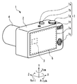
- the imaging device 1 includes an imaging device 3 such as a CCD or a CMOS image sensor, an image display device 6, an input device 7, and a control unit 10.
- the imaging apparatus 1 includes a main body 2 that houses the imaging element 3 and the control unit 10, and an imaging lens 4 that is fixed to the main body 2, and is imaged by the imaging lens 4. It has the form of a so-called digital camera that stores the optical image as electronic data.
- the imaging device 1 may be a so-called interchangeable lens digital camera in which the imaging lens 4 can be removed from the main body 2, or a lens-integrated digital camera in which the imaging lens 4 cannot be removed from the main body 2. It may be a camera.
- the optical axis direction of the imaging lens 4 is defined as the Z axis.
- the direction orthogonal to the optical axis and horizontal is the X axis
- the direction orthogonal to and perpendicular to the optical axis is the Y axis.
- the rotation direction around the X axis of the imaging device 1 is referred to as the pitch direction
- the rotation direction around the Y axis is referred to as the yaw direction
- the rotation direction around the Z axis is referred to as the rotation direction. Called the roll direction.
- the image sensor 3 has a rectangular light receiving surface.
- the light receiving surface of the image sensor 3 is disposed so as to be orthogonal to the optical axis of the image pickup lens 4.
- the imaging lens 4 can perform an autofocus operation, and includes an AF mechanism unit 4a that moves some or all of the lenses to change the focusing distance.
- the imaging lens 4 is a so-called zoom lens that can change the focal length.
- the zoom operation of the imaging lens 4 may be in the form of manual zoom performed by the force input from the user, or the form of electric zoom performed by the force generated by the electric motor incorporated in the imaging lens 4. It may be.
- the imaging lens 4 of the present embodiment includes a focal length detection unit 4b that outputs information on the current focal length of the imaging lens 4 to the control unit 10.
- the configuration of the focal length detection unit 4b is a known technique such as a configuration in which a focal length is detected using a rotary encoder, or a number of pulses for operating a stepping motor for zoom operation is counted.
- the focal length detection unit 4b may be included in the control unit 10.
- the imaging device 1 may include a lens shutter mechanism or a focal plane shutter mechanism.
- the imaging device 1 may include an aperture mechanism in the imaging lens 4.
- the image display device 6 includes, for example, a liquid crystal display device or an organic EL display device, and displays an image.
- the image display device 6 displays a graphical user interface (GUI) of the imaging device 1, displays a live view that functions as a finder during an imaging operation, displays recorded image data, and the like.
- GUI graphical user interface
- the image display device 6 is disposed in the main body 2.
- the image display device 6 may be separated from the main body 2 and may be disposed in another electronic device that is connected to the main body 2 by wired communication or wireless communication.
- the input device 7 is composed of one or a plurality of operation members such as a lever switch, a dial switch, a button switch, and a touch sensor for the user to input an operation instruction of the imaging device 1.
- the input device 7 includes a power operation switch 7a, a release switch 7b, a four-way switch 7c, a dial switch 7d, a touch panel 7e, and a two-way switch 7f.
- the touch panel 7 e is disposed on the display surface of the image display device 15.
- all members constituting the input device 7 are provided in the imaging device 1 as an example.
- the configuration of the input device 7 is not limited to this embodiment.
- part or all of the input device 7 is separated from the main body 2 and is connected to the main body 2 by wired communication or wireless communication. It may be arranged in another electronic device.
- the release switch 7b is a so-called two-stage push button switch including a first release switch and a second release switch that are operated by different pushing amounts or different pushing forces.
- the first release switch is turned on first, and then the second release switch is turned on.
- the state where only the first release switch is in the ON state is a so-called half-pressed state, and the state where the second release switch is in the ON state is a so-called fully-pressed state.
- the control unit 10 includes a CPU (arithmetic device) 11, a RAM (storage device) 12, a flash memory (auxiliary storage device) 13, an image processing unit 16, an input / output device, a power control device, and the like. It has the structure which controls the operation
- the control program for the imaging apparatus 1 is stored in the flash memory 13 or the like that is a nonvolatile storage medium.
- the control unit 10 is electrically connected to the image sensor driving unit 8.
- the image sensor driving unit 8 drives the image sensor 3 under the control of the control unit 10.
- the image sensor driving unit 8 converts the two-dimensional image signal output from the image sensor 3 into primary image data that is a digital signal.
- the axis along the vertical direction in the visual field is the y axis
- the axis along the horizontal direction in the visual field is the x axis.
- the image sensor 3 and the image sensor drive unit 8 are shown as separate bodies, but the image sensor drive unit 8 may be integrally included in the image sensor 3.
- the RAM 12 has a plurality of storage areas for a control program 12a, an image data buffer 12b, and a log information buffer 12c.
- the control program 12a is a storage area for storing a control program read from the flash memory 13 when the imaging apparatus 1 is powered on.
- the image data buffer 12b is a storage area for storing primary image data output from the image sensor driving unit 8 and secondary image data generated by the image processing unit 16 described later.
- the data stored in the image data buffer 12b is simply referred to as image data when it is not necessary to distinguish between primary image data and secondary image data.
- the image data buffer 12b may be a storage area provided in a video memory dedicated to image data handled by the image processing unit 16.
- the log information buffer 12c is a storage area for storing variables used for execution of trapezoidal distortion correction processing described later.
- the AF control unit 14 detects the focus state of the imaging lens 4 on the light receiving surface of the imaging device 3 and controls the autofocus operation by the imaging device 1. More specifically, the AF control unit 14 controls the AF mechanism unit 4a to change the in-focus distance while detecting the contrast in the AF region which is a predetermined region in the primary image data. Set to the in-focus state. That is, the imaging apparatus 1 of the present embodiment can perform an autofocus operation generally called a contrast detection method. Note that the form of the autofocus operation of the imaging apparatus 1 is not limited to the above-described contrast detection method.
- the imaging apparatus 1 includes an imaging element 3 in which a distance measuring sensor that detects a phase difference of a subject image is disposed on an imaging surface, and drives the imaging lens 4 based on a defocus amount detected by the distance measuring sensor.
- An autofocus operation that is generally referred to as a phase difference detection method may be possible.
- the AF area is a part of the rectangular primary image data.
- the coordinates and size of the AF area in the primary image data may be fixed or may be changed according to the operation of the input device 7 by the user. Further, the coordinates and size of the AF area in the primary image data may be changed automatically by the control unit 10 based on a predetermined program.
- the coordinates of the AF area in the primary image data can be changed.
- the user can determine the coordinates of the AF area by the input device 7 such as the touch panel 7e or the four-way switch 7c. It is done by operating.
- the AE control unit 15 controls the exposure amount for the primary image data acquired from the image sensor 3.
- the AE control unit 15 calculates an exposure value based on the subject brightness obtained from the primary image data.
- the image processing unit 16 performs predetermined image processing on the image data stored in the image data buffer 12b.
- the image data that has been subjected to image processing by the image processing unit 16 is referred to as secondary image data.
- the image processing unit 16 of the present embodiment includes a trapezoidal distortion correction coefficient calculation unit 16a and a correction processing unit 16b for performing trapezoidal correction described later on the image data.
- the trapezoidal correction coefficient calculation unit 16a uses the value of the focal length of the imaging lens 4 obtained from the focal length detection unit 4b and the value of the correction angle (described later) input via the input device 7 to calculate the keystone correction. A correction coefficient necessary for executing the process is calculated.
- the correction processing unit 16b performs image interpolation processing with coordinate conversion on the primary image data based on the correction coefficient calculated by the trapezoidal correction coefficient calculation unit 16a.
- the image interpolation processing performs image interpolation processing such as bicubic interpolation and bilinear interpolation.
- the functional configurations of the AF control unit 14, the AE control unit 15, and the image processing unit 16 described above are included in the control unit 10.
- the functional configurations of the AF control unit 14, the AE control unit 15, and the image processing unit 16 may be, for example, a form using dedicated hardware such as a dedicated processor circuit that executes each function.
- the imaging apparatus 1 of the present embodiment includes a power connection unit 21 connected to a commercial power source, a power source 20 such as an AC adapter or a battery, and a storage medium connection unit 23 connected to a storage medium 22 such as a flash memory card.
- a power connection unit 21 connected to a commercial power source
- a power source 20 such as an AC adapter or a battery
- a storage medium connection unit 23 connected to a storage medium 22 such as a flash memory card.
- the power source 20 is a battery and is detachably accommodated in the main body 2.
- the storage medium 22 is a flash memory card and is detachably accommodated in the main body 2.
- the battery and the storage medium 22 serving as the power source 20 may be fixed in the main body 2.
- the storage medium 22 may be arranged in another electronic device that is separated from the main body 2 and connected to the main body 2 by wired communication or wireless communication.
- the trapezoidal correction process is generally a virtual that directly faces a subject by performing geometric deformation processing for correcting trapezoidal distortion on primary image data captured at a position not facing the subject. This is a process of generating secondary image data as if it were captured from a specific viewpoint.
- the orientation of the imaging device 1 is in the pitch direction (in the vertical direction and the inclination angle is relative to the position facing the subject.
- the orientation of the imaging device 1 is in the pitch direction (in the vertical direction and the inclination angle is relative to the position facing the subject.
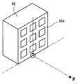
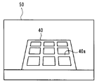
- the front surface 40 a that is a rectangle of the building 40 is imaged by the imaging device 1 so as to look up from the actual viewpoint P close to the ground, as shown in FIG.
- the front surface 40a has a trapezoidally distorted shape.
- the imaging apparatus 1 is in a posture in which the optical axis of the imaging lens 4 is directed upward by a first angle ⁇ y from the horizontal to the pitch direction.
- the reason why the front surface 40a is distorted on the primary image data 50 is that the photographing magnification changes in the vertical direction as the distance from the imaging device 1 to the front surface 40a increases as the distance increases from bottom to top.
- the front surface 40a has a rectangular shape on the primary image data 50 as shown in FIG. .
- the subject image in the primary image data 50 taken from the real viewpoint P has a shape that approximates the subject image taken from the virtual viewpoint P ′, which is a virtual viewpoint, as shown in FIG.
- the primary image data 50 is transformed into secondary image data 50 ′.
- the primary image data 50 on the plane A parallel to the light receiving surface of the image sensor 3 is projected onto the plane B inclined by the first angle ⁇ y in the pitch direction with respect to the plane A.
- the applied secondary image data 50 ' is applied to the plane A.
- step S31 the value of the focal length f of the imaging lens 4 is acquired from the focal length detection unit 4b and stored in the log information buffer 12c of the RAM 12.
- the correction angle is acquired and stored in the log information buffer 12c of the RAM 12.
- the correction angle is a first angle ⁇ y that is an angle formed in the pitch direction with respect to the light receiving surface of the image sensor 3 and an angle that is formed in the yaw direction with respect to the light receiving surface of the image sensor 3. It includes two angle values with a certain second angle ⁇ x.
- the value of the correction angle is determined by the user operating the input device 7. For example, the value of the first angle ⁇ y increases or decreases when the user operates the four-way switch 7c in the vertical direction, and the value of the second angle ⁇ x increases or decreases when the user operates the four-way switch 7c in the horizontal direction. To do. Further, for example, the values of the first angle ⁇ y and the second angle ⁇ x may be increased or decreased according to the direction of the drag operation that the user traces on the touch panel 7e. The value of the correction angle may be continuously changed or may be changed stepwise.
- step S33 the primary image data 50 is subjected to trapezoidal correction processing using the focal length f value and the correction angle value stored in the log information buffer 12c to generate secondary image data 50 ′. To do.
- the following mathematical formula (1) is expressed by the coordinates (x, y) of the primary image data 50 of the plane A and the coordinates (x of the secondary image data 50 ′ of the plane B inclined by the angle ⁇ with respect to the plane A in the pitch direction. ', Y').
- k1 and k2 are conversion coefficients
- k1 cos ⁇ sin ⁇ ⁇ tan ⁇
- k2 H-2sin ⁇ ⁇ tan ⁇ It is.
- H is the number of pixels on a predetermined side of the effective pixel region of the image sensor 3 corresponding to the correction angle input by the user via the input device 7.
- H is the effective pixel region of the image sensor 3.
- the number of pixels in the short side direction is obtained by dividing the length (pixel pitch) per pixel in the image sensor 3 with respect to the length in the short side direction of the effective pixel region of the image sensor 3. Result.
- H is the long side of the effective pixel area of the image sensor 3
- the number of pixels corresponding to H is obtained by dividing the length (pixel pitch) per pixel in the image sensor 3 with respect to the length in the long side direction of the effective pixel region of the image sensor 3.
- angle ⁇ is calculated by the following mathematical formula (2).
- L is the effective pixel area of the image sensor 3. (The unit is shown in mm).
- L is the long side of the effective pixel area of the image sensor 3
- the length in the direction (unit is mm).
- f is a focal length of the imaging lens 4 (unit is shown in mm). That is, the angle ⁇ is a half value of the angle of view in the direction in which the trapezoidal distortion of the imaging apparatus 1 is performed.
- the value of the focal length f may be a value input via the input device 7 by the user.
- the user inputs the value of the focal length f, so that the trapezoid desired by the user is obtained. Correction can be performed.
- the user by enabling the user to input the value of the focal length f, it is possible to perform keystone correction that produces a sense of perspective according to the user's intention.
- the user selects whether to perform the keystone correction using the value acquired from the imaging lens 4 or the value input by the user. Means may be provided.
- step S33 a trapezoidal correction process in the short side direction is performed on the primary image data 50 by using the above formulas (1) and (2) to generate secondary image data 50 '.
- the coordinates (x ′, y ′) of the secondary image data after the keystone correction are calculated by back calculating the relational expression with the coordinates (x, y) of the primary image data 50 indicated by the above formula (1).
- step S33 using the above equations (1) and (2), the coordinates (x ', y') of the primary image data 50 with respect to the coordinates (x ', y') after the keystone correction are performed. , Y) is defined.
- the relational expression based on the defined mathematical formula (1) is reversely calculated, and the coordinates (x ′, y ′) of the secondary image data 50 ′ are calculated from the coordinates (x, y) of the input primary image data 50.
- the trapezoid correction process has been described as being performed in the vertical direction (pitch direction) in the field of view.
- the trapezoidal correction process is similarly performed in the horizontal direction (yaw direction) in the field of view.
- the trapezoidal correction processing is performed, for example, by using the primary image data captured from the actual viewpoint P where the angle between the front surface 40a of the building 40 and the optical axis of the imaging lens 4 in the horizontal direction is not a right angle as the surface of the building 40.
- a trapezoidal correction is performed to approximate an image taken from a virtual viewpoint P ′ directly facing 40a. Under such shooting conditions, the rectangular front surface 40a of the building 40 is asymmetric in the left-right direction in the primary image data.
- the trapezoidal correction process is performed by converting the primary image data 50 or the secondary image data 50 ′ subjected to the trapezoidal correction process in the pitch direction to the plane B inclined by the second angle ⁇ x with respect to the plane A in the yaw direction.
- the image subjected to the deformation process to be projected is defined as secondary image data 50 ′.
- the coordinates (x ′, y ′) of the secondary image data 50 ′ of the plane B inclined by the second angle ⁇ x in the yaw direction with respect to the plane A are 1 Relationship in which the variable (x, y) of the coordinate related to the next image is replaced with (y, x), and the variable (x ′, y ′) of the coordinate related to the secondary image is replaced with (y ′, x ′). It becomes an expression.
- L [mm] related to the value of ⁇ is the length of the effective pixel region of the image sensor 3 in the long side direction.
- the image processing unit 16 forms the primary image data 50 in the pitch direction with respect to the plane A parallel to the light receiving surface of the image sensor 3, with respect to the light receiving surface. Then, the secondary image data subjected to the deformation process for projecting onto the plane B forming the second angle ⁇ x in the yaw direction is generated.
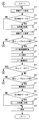
- the flowchart shown in FIG. 3 shows an operation when the power supply of the imaging apparatus 1 is on and in the imaging operation mode.
- the imaging operation mode as an initial state, primary image data is acquired from the imaging device 3 every predetermined frame period, and secondary image data after image processing by the image processing unit 16 is sequentially performed on the image display device 6. Live view display operation for display output.
- the imaging device 1 executes an operation in which the imaging device 1 stores the subject image as electronic data in the storage medium 22 in response to an operation input to the release switch 7b.
- the imaging apparatus 1 may be capable of executing a reproduction mode in which electronic image data stored in the storage medium 22 is reproduced and displayed on the image display apparatus 6.
- the imaging operation mode is, for example, when the user operates the power operation switch 7a to input the imaging apparatus 1 to be in a dormant state, when an operation to switch to another operation mode is input, or when the control unit 10 If it is determined to enter the hibernation state, the process ends.
- the determination process for ending the imaging operation mode is omitted in the flowchart of FIG.
- the imaging operation mode power is supplied to the imaging device 3 and the imaging device driving unit 8. Further, in order to perform the live view display operation, the acquisition of the primary image data 50 from the image sensor 3 is performed every predetermined frame period.
- the imaging operation mode first, in step S11, the primary image data 50 output from the imaging element driving unit 8 is stored in the image data buffer 12b of the RAM 12.
- step S12 it is determined whether or not the keystone correction mode is selected by the user.
- the trapezoidal correction mode is an operation mode in which the imaging apparatus 1 performs the above-described trapezoidal correction process on the primary image data 50 using the image processing unit 16. Whether or not the trapezoid correction mode is selected can be switched by the user operating the four-way switch 7c or the touch panel 7e on the GUI displayed on the image display device 6, for example.
- step S12 If it is determined in step S12 that the keystone correction mode is selected by the user, the process proceeds to step S14 after the keystone correction process shown in FIG. 4 is executed in step S13.
- step S13 secondary image data 50 'obtained by performing keystone correction processing on the primary image data 50 is stored in the image data buffer 12b.
- step S13 is skipped and the process proceeds to step S14.
- step S14 the image data stored in the image data buffer 12b of the RAM 12 is displayed on the image display device 6. If step S13 is skipped, the primary image data 50 that has not been subjected to the trapezoidal correction process is displayed on the image display device 6 in step S14. On the other hand, when step S13 is executed, the secondary image data 50 'subjected to the trapezoidal correction process is displayed on the image display device 6.
- the field of view of the imaging device 1 is not rectangular as shown in FIG. 9.
- the entire secondary image data 50 ' may be displayed on the image display device 6, or a part of the secondary image data 50' trimmed into a rectangular area as shown by a two-dot chain line in FIG. These areas may be displayed on the image display device 6.
- step S15 it is determined whether or not the first release switch of the release switch 7b is in an ON state. That is, it is determined whether or not the release switch 7b is half pressed.
- step S15 If it is determined in step S15 that the first release switch of the release switch 7b is in the OFF state, the process returns to step S11. That is, until the release switch 7b is operated, the operations from step S11 to step S14 are repeatedly executed in synchronization with a predetermined frame period.
- the live view in which the primary image data 50 or the secondary image data 50 ′ displayed on the image display device 6 is constantly updated by repeating the operations from step S11 to step S14 in synchronization with a predetermined frame period. Operation is performed.
- step S15 if it is determined in step S15 that the first release switch of the release switch 7b is in the ON state, the process proceeds to step S16.
- step S16 the coordinates of the AF area are acquired. As described above, the coordinates of the AF area in the primary image data 50 are values specified by the user.
- step S17 the AF control unit 14 performs an autofocus operation using the contrast value in the AF area of the coordinates acquired in step S16.
- the autofocus operation is performed using the defocus amount detected by the distance measuring sensor.
- step S18 a frame-like AF area icon indicating the position and size of the AF area is superimposed on the live view display displayed on the image display device 6 and displayed.
- step S19 it is determined whether or not the first release switch of the release switch 7b is in an OFF state. If it is determined in step S19 that the first release switch of the release switch 7b is in the OFF state, it is determined that the user has stopped the framing operation, and the process returns to step S11 again.
- step S19 if it is determined in step S19 that the first release switch of the release switch 7b is in the ON state, the process proceeds to step S20.
- step S20 it is determined whether or not the second release switch of the release switch 7b is in an ON state.
- step S20 If it is determined in step S20 that the second release switch of the release switch 7b is in the OFF state, the process returns to step S11.
- step S20 when it is determined in step S20 that the second release switch of the release switch 7b is in the ON state, the process proceeds to step S21 to execute an imaging operation.
- the imaging operation the imaging device 3 is driven so that imaging using the exposure value calculated by the AE control unit 15 is performed, and the obtained image data is stored in the image data buffer 12b as imaging image data.
- step S22 it is determined whether or not the keystone correction mode is selected by the user. If it is determined in step S22 that the trapezoid correction mode has been selected by the user, the process proceeds to step S23, and the above-described trapezoid correction process is performed on the image data for imaging.
- step S24 the imaging image data that has been subjected to the trapezoidal correction process is stored in the storage medium 22 as an electronic file of a predetermined format.
- step S23 is skipped and the process proceeds to step S24, where the image data for imaging is stored as an electronic file in a predetermined format. Store in the medium 22.
- the imaging apparatus 1 includes the imaging element 3 that acquires primary image data every predetermined frame period, and the focal point that acquires the focal length of the imaging lens 4 in synchronization with the frame period.
- the distance detection unit 4b includes two values including a first angle ⁇ y that is an angle formed in the pitch direction with respect to the light receiving surface of the image sensor 3 and a second angle ⁇ x that is an angle formed in the yaw direction with respect to the light receiving surface.
- An image processing unit 16 for generating secondary image data subjected to a deformation process for projecting onto a plane having a second angle ⁇ x in the yaw direction with respect to the light receiving surface, and based on the secondary image data in synchronization with the frame period.
- Image display device for displaying images It includes a 6, a.
- trapezoidal correction processing for correcting the trapezoidal distortion of the subject can be executed in two directions of the pitch direction and the yaw direction of the imaging apparatus 1.
- the degree of the trapezoid correction process (correction angle) can be freely changed by operating the input device 7.
- the secondary image data 50 ′ which is the result of the keystone correction process, is displayed on the image display device 6 as a live view, and the result of changing the correction angle is immediately displayed in the live view. Reflected. For this reason, by using the imaging apparatus 1 of the present embodiment, the user can perform the trapezoidal correction process on the image as intended while confirming the subject composition.
- the imaging apparatus 1 includes a rotation correction unit 16 c in the image processing unit 16, and performs rotation correction processing that rotates primary image data in the roll direction in the trapezoid correction processing in step S ⁇ b> 23. It is feasible.
- the rotation correction unit 16c performs horizontal axis (X axis) and vertical axis (Y axis) according to the correction angle (third angle ⁇ ) in the roll direction input to the primary image data via the input unit 7. ) Is subjected to rotation correction processing for rotating coordinate conversion.
- the value of the third angle ⁇ is input by operating the two-way switch 7f by the user as an example in the present embodiment. For example, the value of the third angle ⁇ increases when the two-way switch 7f is operated on one side, and the value of the third angle ⁇ decreases when the two-way switch 7f is operated on one side.
- the imaging device 1 when the imaging device 1 is arranged with an inclination of ⁇ in the roll direction, the horizontal and vertical directions of the subject in the primary image data 150 and the primary image data 150 as shown in FIG.
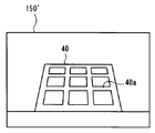
- the x-axis and y-axis which are the coordinate axes, are not coincident. Even if the keystone correction processing in the pitch direction and the yaw direction is performed on the primary image data 150 in this case, secondary image data on which the keystone correction desired by the user has been performed may not be obtained.
- the imaging apparatus 1 performs a rotation correction process on the primary image data 150 before performing the keystone correction process, and the horizontal and vertical directions of the subject and the x axis and y in the image data. Match the axis.
- FIG. 11 is a flowchart of the trapezoid correction process in the imaging apparatus 1 of the present embodiment.
- step S131 an operation similar to that in step S31 of the first embodiment is performed. That is, the value of the focal length f of the imaging lens 4 of the imaging lens 4 is acquired and stored in the log information buffer 12 c of the RAM 12.
- step S132 the value of the third angle ⁇ which is the correction angle in the roll direction is acquired and stored in the log information buffer 12c of the RAM 12. As described above, the value of the third angle ⁇ is input by the user via the input unit 7.
- step S133 the rotation correction unit 16c performs rotation correction on the horizontal axis (X axis) and the vertical axis (Y axis) with respect to the primary image data according to the value of the third angle ⁇ .
- the rotation correction unit 16c performs rotation correction on the horizontal axis (X axis) and the vertical axis (Y axis) with respect to the primary image data according to the value of the third angle ⁇ .
- Rotational coordinate transformation calculation processing means uses rotational coordinate transformation processing using primary transformation processing based on the following mathematical formula (3).
- the following mathematical formula (3) is expressed by the coordinates (x, y) of the primary image data 150 and the coordinates (x ′, y) of the secondary image data 150 ′ rotated by the angle ⁇ in the roll direction with respect to the primary image data 150.
- ') Is a formula representing the relationship with.
- step S134 the same operation as step S32 of the first embodiment is performed. That is, the values of the first angle ⁇ y and the second angle ⁇ x, which are correction angles in the pitch direction and the yaw direction, are acquired and stored in the log information buffer 12c of the RAM 12.
- step S135 the same operation as in step S33 of the first embodiment is performed. That is, using the value of the focal length f and the values of the first angle ⁇ y and the second angle ⁇ x stored in the log information buffer 12c, the keystone correction process is performed on the secondary image data 150 ′ obtained by the execution of step S133. Secondary image data 150 "is generated. In the secondary image data 150", the trapezoidal distortion of the building 40 that is the subject is corrected as shown in FIG.
- means for performing rotation correction processing on the primary image data in the image processing unit 16 is shown.
- the means for the rotation correction processing is not limited to this embodiment.
- a rotation mechanism that rotates the image pickup device 3 in the roll direction is installed in the image pickup apparatus 1, and the image pickup device 3 is moved to the third angle ⁇ .
- the rotation correction process can also be performed by rotating according to the value of.
- the rotation correction process is performed so that the horizontal or vertical direction of the subject image corresponds to the yaw direction and the pitch direction related to the keystone correction. be able to.
- the rotation correction process is performed so that the horizontal or vertical direction of the subject image corresponds to the yaw direction and the pitch direction related to the keystone correction. be able to.
- the present invention is not limited to the above-described embodiment, and can be appropriately changed without departing from the gist or concept of the invention that can be read from the claims and the entire specification.
- the display method of the apparatus and the imaging apparatus is also included in the technical scope of the present invention.
- the imaging apparatus according to the present invention is not limited to the form of the digital camera as described in the above-described embodiment, and may be, for example, the form of an electronic device having an imaging function.
- electronic devices having an imaging function include portable communication terminals, game machines, digital media players, watches, voice recorders, binoculars, and the like.
Landscapes
- Engineering & Computer Science (AREA)
- Multimedia (AREA)
- Signal Processing (AREA)
- Physics & Mathematics (AREA)
- General Physics & Mathematics (AREA)
- Theoretical Computer Science (AREA)
- Studio Devices (AREA)
- Image Processing (AREA)
Abstract
撮像装置は、所定のフレーム周期毎に1次画像データを取得する撮像素子と、前記フレーム周期に同期して撮像レンズの焦点距離である第1の焦点距離を取得する焦点距離検出部と、第1角度及び第2角度からなる2つの値を含む補正角度を入力する構成を有する入力装置と、前記フレーム周期に同期して、前記第1の焦点距離の値及び前記補正角度の値を用い、前記1次画像データを、前記受光面に対してピッチ方向に前記第1角度をなし、前記受光面に対してヨー方向に前記第2角度をなす平面上に投影する変形処理を施した2次画像データを生成する画像処理部と、前記フレーム周期に同期して、前記2次画像データに基づく画像を表示する画像表示装置と、を備える。
Description
本発明は、撮像素子及び画像表示装置を備える撮像装置及び撮像装置の表示方法に関する。
デジタルカメラ等の撮像装置を用いて例えば被写体である建築物を見上げる姿勢で撮像する場合、画像中において建築物は上すぼまりに台形状に歪む。例えば、日本国特開2007-43545号公報には、被写体を撮影するときの撮像装置の姿勢を加速度センサによって検出し、被写体の台形状の歪みを自動的に補正する台形補正処理を行う技術が開示されている。
日本国特開2007-43545号公報に開示の技術のように、加速度センサによって撮像装置の姿勢を検出する場合、撮像装置の上下方向(ピッチ方向)の傾きしか検出できないため、使用者が望む台形補正処理が行われない場合がある。
本発明は、上述した点に鑑みてなされたものであって、使用者の意図通りに画像に台形補正処理を行うことが可能な撮像装置及び撮像装置の表示方法を提供することを目的とする。
本発明の一態様の撮像システムは、 本発明の一態様の撮像装置は、撮像レンズの光軸に受光面が直交するように配置され、所定のフレーム周期毎に1次画像データを取得する撮像素子と、前記フレーム周期に同期して前記撮像レンズの焦点距離である第1の焦点距離を取得する焦点距離検出部と、前記受光面に対してピッチ方向になす角度である第1角度、及び前記受光面に対してヨー方向になす角度である第2角度からなる2つの値を含む補正角度を入力する構成を有する入力装置と、前記フレーム周期に同期して、前記第1の焦点距離の値及び前記補正角度の値を用い、前記1次画像データを、前記受光面に対してピッチ方向に前記第1角度をなし、前記受光面に対してヨー方向に前記第2角度をなす平面上に投影する変形処理を施した2次画像データを生成する画像処理部と、前記フレーム周期に同期して、前記2次画像データに基づく画像を表示する画像表示装置と、を備える。
また、本発明の一態様の撮像装置の表示方法は、撮像レンズの光軸に受光面が直交するように配置され、所定のフレーム周期毎に1次画像データを取得する撮像素子と、前記フレーム周期に同期して前記撮像レンズの焦点距離を取得する焦点距離検出部と、前記光軸に対してピッチ方向になす角度である第1角度、及び前記光軸に対してヨー方向になす角度である第2角度からなる2つの値を含む補正角度を入力する入力装置と、画像表示装置とを備える撮像装置の表示方法であって、前記フレーム周期に同期して、前記焦点距離の値及び前記補正角度の値を用い、前記1次画像データを、前記光軸に対してピッチ方向に前記第1角度をなし、前記光軸に対してヨー方向に前記第2角度をなす平面上に投影する変形処理を施した2次画像データを生成するステップと、前記フレーム周期に同期して、前記2次画像データに基づく画像を前記画像表示装置に表示するステップと、を含む。
以下に、本発明の好ましい形態について図面を参照して説明する。なお、以下の説明に用いる各図においては、各構成要素を図面上で認識可能な程度の大きさとするため、構成要素毎に縮尺を異ならせてあるものであり、本発明は、これらの図に記載された構成要素の数量、構成要素の形状、構成要素の大きさの比率、及び各構成要素の相対的な位置関係のみに限定されるものではない。 以下に、本発明の好ましい形態について図面を参照して説明する。なお、以下の説明に用いる各図においては、各構成要素を図面上で認識可能な程度の大きさとするため、構成要素毎に縮尺を異ならせてあるものであり、本発明は、これらの図に記載された構成要素の数量、構成要素の形状、構成要素の大きさの比率、及び各構成要素の相対的な位置関係のみに限定されるものではない。
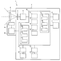
図1及び図2に示すように、撮像装置1は、CCDやCMOSイメージセンサ等の撮像素子3、画像表示装置6、入力装置7及び制御部10を備える。本実施形態では一例として、撮像装置1は、撮像素子3及び制御部10を収容する本体部2と、当該本体部2に固定される撮像レンズ4とを具備し、撮像レンズ4によって結像された光学像を電子データとして記憶する、いわゆるデジタルカメラの形態を有する。なお、撮像装置1は、撮像レンズ4を本体部2から取り外し可能な、いわゆるレンズ交換式のデジタルカメラであってもよいし、撮像レンズ4を本体部2から取り外すことのできないレンズ一体式のデジタルカメラであってもよい。
以下では、撮像装置1の姿勢方向の定義として、撮像レンズ4の光軸方向をZ軸と定義する。また、撮像装置1を正立状態とした場合に、光軸と直交しかつ水平となる方向をX軸とし、光軸と直交しかつ垂直となる方向をY軸とする。また、撮像装置1の姿勢変化の方向を表すために、撮像装置1のX軸周りの回転方向をピッチ方向と称し、Y軸周りの回転方向をヨー方向と称し、Z軸周りの回転方向をロール方向と称する。
撮像素子3は、矩形の受光面を有する。撮像素子3の受光面は、撮像レンズ4の光軸に直交するように配設されている。撮像レンズ4は、オートフォーカス動作が可能であり、合焦距離を変化させるために一部又は全部のレンズを移動させるAF機構部4aを備える。また、本実施形態では一例として、撮像レンズ4は、焦点距離を変更可能な、いわゆるズームレンズである。撮像レンズ4のズーム動作は、使用者から入力される力によって行われる手動ズームの形態であってもよいし、撮像レンズ4内に組み込まれた電動モータが発生する力によって行われる電動ズームの形態であってもよい。
本実施形態の撮像レンズ4は、撮像レンズ4の現在の焦点距離の情報を制御部10に出力する焦点距離検出部4bを備える。焦点距離検出部4bの構成は、ロータリーエンコーダを用いて焦点距離を検出する形態や、ズーム動作用のステッピングモータを動作させるパルス数をカウントする形態等、公知の技術である。なお、例えば撮像装置1がレンズ一体式である場合には、焦点距離検出部4bは、制御部10に含まれる形態であってもよい。
撮像装置1は、レンズシャッタ機構又はフォーカルプレーンシャッタ機構を備えていてもよい。また、撮像装置1は、撮像レンズ4に、絞り機構を備えていてもよい。
画像表示装置6は、例えば液晶表示装置又は有機EL表示装置等からなり、画像を表示する。画像表示装置6は、撮像装置1のグラフィカル・ユーザー・インターフェース(GUI)の表示、撮像動作中にファインダーとして機能するライブビューの表示、及び記録された画像データの表示等を行う。
本実施形態では一例として、画像表示装置6は、本体部2に配設されている。なお、画像表示装置6は、本体部2と分離されており、かつ本体部2と有線通信又は無線通信により接続される他の電子機器に配設される形態であってもよい。
入力装置7は、例えばレバースイッチ、ダイヤルスイッチ、ボタンスイッチ、タッチセンサ等の、使用者が撮像装置1の動作指示を入力するための一つ又は複数の操作部材からなる。
本実施形態では一例として、入力装置7は、電源操作スイッチ7a、レリーズスイッチ7b、4方向スイッチ7c、ダイヤルスイッチ7d、タッチパネル7e及び2方向スイッチ7fを備える。タッチパネル7eは、画像表示装置15の表示面上に配設されている。なお、図示する本実施形態では、一例として入力装置7を構成する全ての部材が撮像装置1に設けられている。しかし、入力装置7の構成は本実施形態に限られるものではなく、例えば入力装置7の一部又は全部は、本体部2と分離されており、かつ本体部2と有線通信又は無線通信により接続される他の電子機器に配設される形態であってもよい。
レリーズスイッチ7bは、異なる押し込み量又は異なる押し込み力によって動作する第1レリーズスイッチ及び第2レリーズスイッチを備えた、いわゆる2段の押しボタンスイッチである。本実施形態では、レリーズスイッチ7bに加える押し込み力を増大させていった場合、先に第1レリーズスイッチがON状態となり、次に第2レリーズスイッチがON状態となる。第1レリーズスイッチのみがON状態である状態は、いわゆる半押しの状態であり、第2レリーズスイッチがON状態である状態は、いわゆる全押しの状態である。
制御部10は、CPU(演算装置)11、RAM(記憶装置)12、フラッシュメモリ(補助記憶装置)13、画像処理部16、入出力装置及び電力制御装置等を具備して構成されており、撮像装置1の後述する動作を、所定のプログラムに基づいて制御する構成を有している。本実施形態では、撮像装置1の制御プログラムは、不揮発性の記憶媒体であるフラッシュメモリ13等に記憶されている。
制御部10は、撮像素子駆動部8に電気的に接続されている。撮像素子駆動部8は、制御部10の制御にしたがって撮像素子3を駆動する。また、撮像素子駆動部8は、撮像素子3から出力された2次元の画像信号をデジタル信号である1次画像データに変換する。ここで、1次画像データ中の座標について、撮像装置1を正立状態に保持した場合において視野中の鉛直方向に沿う軸をy軸とし、視野中の水平方向に沿う軸をx軸とする。なお、本実施形態では一例として、撮像素子3と撮像素子駆動部8とを別体として示しているが、撮像素子駆動部8は撮像素子3内に一体に含まれる形態であってもよい。
RAM12には、制御プログラム12a、画像データバッファ12b及びログ情報バッファ12cの複数の記憶エリアを有する。制御プログラム12aは、撮像装置1の電源投入時に、フラッシュメモリ13から読み出した制御プログラムを記憶する記憶エリアである。
画像データバッファ12bは、撮像素子駆動部8から出力された1次画像データや、後述する画像処理部16によって生成された2次画像データを記憶する記憶エリアである。以下では、画像データバッファ12bに記憶されているデータについて、1次画像データ及び2次画像データの区別が不要である場合には、単に画像データと称する。
なお、画像データバッファ12bは、画像処理部16が扱う画像データ専用のビデオメモリに設けられる記憶エリアであってもよい。また、ログ情報バッファ12cは、後述する台形歪補正処理の実行に用いる変数を記憶する記憶エリアである。
AF制御部14は、撮像素子3の受光面での撮像レンズ4の焦点状態を検出し、撮像装置1によるオートフォーカス動作を制御する。より詳しくは、AF制御部14は、1次画像データ中の所定の領域であるAF領域内のコントラストを検出しつつ、AF機構部4aを制御して合焦距離を変化させて撮像レンズ4を合焦状態とする。すなわち、本実施形態の撮像装置1は、一般にコントラスト検出方式と称されるオートフォーカス動作が可能である。なお、撮像装置1のオートフォーカス動作の形態は、前述したコントラスト検出方式に限られるものではない。例えば、撮像装置1は、撮像面に被写体像の位相差を検出する測距センサが配置された撮像素子3を備え、測距センサによって検出されたデフォーカス量に基づいて撮像レンズ4を駆動し合焦状態とする、一般に位相差検出方式と称されるオートフォーカス動作が可能であってもよい。
本実施形態では、AF領域は、矩形状である1次画像データ中の一部の領域である。1次画像データ中におけるAF領域の座標及び大きさは、固定されていてもよいし、使用者による入力装置7の操作に応じて変更可能であってもよい。また、1次画像データ中におけるAF領域の座標及び大きさは、これらを制御部10が所定のプログラムに基づいて自動的に変更する形態であってもよい。
本実施形態では一例として、1次画像データ中のAF領域の座標は変更することが可能であり、このAF領域の座標の決定は、使用者がタッチパネル7eや4方向スイッチ7c等の入力装置7を操作することによって行われる。
AE制御部15は、撮像素子3から取得される1次画像データに対する、露出量の制御を行う。AE制御部15は、1次画像データから得られる被写体輝度に基づいて、露出値を算出する。
画像処理部16は、画像データバッファ12bに記憶されている画像データに所定の画像処理を施す。以下では、画像処理部16によって画像処理を施された後の画像データを、2次画像データと称する。本実施形態の画像処理部16は、画像データに対して後述する台形補正を施すための、台形歪補正係数算出部16a及び補正処理部16bを含む。
台形補正係数算出部16aは、焦点距離検出部4bから得られる撮像レンズ4の焦点距離の値と、入力装置7を介して入力された後述する補正角度の値、を用いて、台形補正の演算処理の実行に必要な補正係数を算出する。補正処理部16bは、台形補正係数算出部16aによって算出された補正係数に基づいて、1次画像データに対して座標変換を伴う画像補間処理を行う。前記画像補間処理は、バイキュービック補間やバイリニア補間等の画像補間処理を実施するものである。
なお、本実施形態では一例として、前述のAF制御部14、AE制御部15及び画像処理部16の機能構成は、制御部10に含まれている。なお、AF制御部14、AE制御部15及び画像処理部16の機能構成は、例えばそれぞれの機能を実行する専用のプロセッサ回路等の専用のハードウェアを用いる形態であってもよい。
また、本実施形態の撮像装置1は、商用電源、ACアダプタ又は電池等の電源20に接続される電源接続部21及び、フラッシュメモリカード等の記憶媒体22に接続される記憶媒体接続部23を備える。本実施形態では一例として、電源20は電池であって、本体部2内に着脱可能に収容される。また、本実施形態では一例として、記憶媒体22はフラッシュメモリカードであって、本体部2内に着脱可能に収容される。なお、電源20となる電池及び記憶媒体22は、本体部2内に固定される形態であってもよい。また、記憶媒体22は、本体部2と分離されており、かつ本体部2と有線通信又は無線通信により接続される他の電子機器に配設される形態であってもよい。
次に、画像処理部16において実行される台形補正処理について、図4に示すフローチャートを参照して説明する。台形補正処理とは、概略的には、被写体に正対していない位置において撮像された1次画像データに対して台形歪みを補正する幾何学的な変形処理を施すことによって、被写体に正対する仮想的な視点から撮像したような2次画像データを生成する処理である。
以下では台形歪みを補正する幾何学的な変形処理について、説明を簡単なものとするために、被写体に正対する位置に対して、撮像装置1の姿勢がピッチ方向(上下方向にあおり傾斜角が生じる方向)に所定の角度をなす位置に配置された場合について説明する。
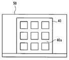
例えば、図5及び図6に示すように、建築物40の矩形である前面40aを、地面に近い実視点Pから見上げるように撮像装置1によって撮像する場合、図7に示すように、1次画像データ50上では、前面40aは上すぼまりに台形に歪んだ形状となる。このとき、実視点Pからの撮像では、撮像装置1は、撮像レンズ4の光軸を水平からピッチ方向に第1角度αyだけ上方に向けた姿勢となる。1次画像データ50上において前面40aが歪むのは、撮像装置1から前面40aへの距離が下から上に向かうほど遠くなることによって、上下方向で撮影倍率が変化するためである。
一方、撮像装置1を建築物40の前面40aに正対する仮想視点P’に配置して撮像する場合には、図8に示すように、1次画像データ50上において前面40aは矩形状となる。
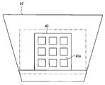
台形補正処理では、実視点Pから撮像した1次画像データ50中の被写体像が、図9に示すように仮想的な視点である仮想視点P’から撮影した被写体像に近似した形状となるように1次画像データ50を変形して、これを2次画像データ50’とする。言い換えれば、撮像素子3の受光面に平行な平面A上の1次画像データ50を、平面Aに対してピッチ方向に第1角度αyだけ傾いた平面Bに投影したものが、台形補正処理が施された2次画像データ50’である。
具体的には、台形補正処理では、まずステップS31において、焦点距離検出部4bから、撮像レンズ4の焦点距離fの値を取得し、RAM12のログ情報バッファ12cに記憶する。
次に、ステップS32において、補正角度を取得し、RAM12のログ情報バッファ12cに記憶する。ここで、補正角度とは、前述のように、撮像素子3の受光面に対してピッチ方向になす角度である第1角度αyと、撮像素子3の受光面に対してヨー方向になす角度である第2角度αxとの2つの角度の値を含む。
補正角度の値は、使用者が入力装置7を操作することによって定められる。例えば、使用者が4方向スイッチ7cを上下方向に操作することによって第1角度αyの値が増減し、使用者が4方向スイッチ7cを左右方向に操作することによって第2角度αxの値が増減する。また例えば、使用者がタッチパネル7e上をなぞるドラッグ操作の方向に応じて、第1角度αy及び第2角度αxの値が増減する形態であってもよい。補正角度の値は、連続的に変化する形態であってもよいし、ステップ状に変化する形態であってもよい。
次に、ステップS33において、ログ情報バッファ12cに記憶されている焦点距離fの値及び補正角度の値を用いて、1次画像データ50に台形補正処理を施し、2次画像データ50’を生成する。
下記数式(1)は、平面Aの1次画像データ50の座標(x,y)と、平面Aに対してピッチ方向に角度αだけ傾いた平面Bの2次画像データ50’の座標(x’、y’)との関係を表す式である。
[数1]
y={H・k1・y’}/{H-k2・y’}
x={H・x’}/{H-k2・y’}
ここで、k1及びk2は変換係数であり、
k1=cosα-sinα・tanβ
k2=H-2sinα・tanβ
である。
y={H・k1・y’}/{H-k2・y’}
x={H・x’}/{H-k2・y’}
ここで、k1及びk2は変換係数であり、
k1=cosα-sinα・tanβ
k2=H-2sinα・tanβ
である。
Hは、使用者によって入力装置7を介して入力された補正角度に対応した撮像素子3の有効画素領域の所定の辺の画素数である。例えば、図7に示すように、撮像素子3の有効画素領域の長辺を水平にして撮影し、視野の上下方向の台形歪みの補正を行う場合には、Hは撮像素子3の有効画素領域の短辺方向の画素数である。具体的には、Hに対応する画素数は、撮像素子3の有効画素領域の短辺方向となる長さに対して、撮像素子3にある1画素あたりの長さ(画素ピッチ)を割り算した結果となる。
また、図示しないが、撮像素子3の有効画素領域の長辺を水平にして撮影し、視野の左右方向の台形歪みの補正を行う場合には、Hは撮像素子3の有効画素領域の長辺方向の画素数である。この場合、Hに対応する画素数は、撮像素子3の有効画素領域の長辺方向となる長さに対して、撮像素子3にある1画素あたりの長さ(画素ピッチ)を割り算した結果となる。
また、角度βは、下記数式(2)によって算出される。
[数2]
β=arctan{L/(2・f)}
Lは、使用者によって入力装置7を介して入力された補正角度に対応した撮像素子3の有効画素領域の所定の辺の長さである(単位はmmで示す)。例えば、図7に示すように、撮像素子3の有効画素領域の長辺を水平にして撮影し、視野の上下方向の台形歪みの補正を行う場合には、Lは撮像素子3の有効画素領域の短辺方向の長さである(単位はmmで示す)。また、図示しないが、撮像素子3の有効画素領域の長辺を水平にして撮影し、視野の左右方向の台形歪みの補正を行う場合には、Lは撮像素子3の有効画素領域の長辺方向の長さである(単位はmmで示す)。fは撮像レンズ4の焦点距離である(単位はmmで示す)。すなわち、角度βは、撮像装置1の台形歪みを行う方向の画角の半分の値である。
β=arctan{L/(2・f)}
Lは、使用者によって入力装置7を介して入力された補正角度に対応した撮像素子3の有効画素領域の所定の辺の長さである(単位はmmで示す)。例えば、図7に示すように、撮像素子3の有効画素領域の長辺を水平にして撮影し、視野の上下方向の台形歪みの補正を行う場合には、Lは撮像素子3の有効画素領域の短辺方向の長さである(単位はmmで示す)。また、図示しないが、撮像素子3の有効画素領域の長辺を水平にして撮影し、視野の左右方向の台形歪みの補正を行う場合には、Lは撮像素子3の有効画素領域の長辺方向の長さである(単位はmmで示す)。fは撮像レンズ4の焦点距離である(単位はmmで示す)。すなわち、角度βは、撮像装置1の台形歪みを行う方向の画角の半分の値である。
なお、焦点距離fの値は、使用者によって入力装置7を介して入力される値であってもよい。例えば、撮像装置1がレンズ交換式であり、焦点距離情報を取得できない撮像レンズ4が装着されている場合には、焦点距離fの値を使用者が入力することによって、使用者が所望する台形補正を実施することができる。また、焦点距離fの値を使用者が入力可能とすることによって、使用者の意図に応じた遠近感を生じさせる台形補正を行うことができる。なお、焦点距離fの値を使用者が入力可能である場合には、撮像レンズ4から取得される値と、使用者によって入力される値のどちらを用いて台形補正を実行するかを選択する手段が設けられてもよい。
ステップS33では、上記数式(1)及び(2)を用いることによって、1次画像データ50に、短辺方向の台形補正処理を実施し、2次画像データ50’を生成する。台形補正後となる2次画像データの座標(x’,y’)は、上記数式(1)が示す1次画像データ50の座標(x,y)との関係式を逆算することによって算出される。より具体的には、ステップS33では、上記数式(1)及び(2)を用い、台形補正後となる2次画像データの座標(x’,y’)に対する1次画像データ50の座標(x,y)の関係式を定義する。次にこの定義した数式(1)に基づく関係式を逆算して、入力される1次画像データ50の座標(x,y)から2次画像データ50’の座標(x’,y’)を求めることによって、図7に一例として示すような1次画像データ50に、ピッチ方向の補正角度入力に応じて、一次画像データ50の短辺方向(図7の例ではy方向)の台形補正処理を実施し、図9に示す様な2次画像データ50’を生成する。
以上の例示では、台形補正処理は視野中の鉛直方向(ピッチ方向)について行われる作用を説明した。なお、台形補正処理は視野中の水平方向(ヨー方向)についても同様に行われる。この場合の台形補正処理は、例えば建築物40の前面40aと撮像レンズ4の光軸との水平方向になす角度が直角でない実視点Pから撮影された1次画像データを、建築物40の表面40aに正対する仮想視点P’から撮影された画像に近似させる台形補正を実行するものである。このような撮影条件では、建築物40の矩形状の前面40aは、1次画像データ中において左右方向に非対称となる。この場合の台形補正処理は、1次画像データ50又はピッチ方向の台形補正処理が施された2次画像データ50’を、平面Aに対してヨー方向に第2角度αxだけ傾いた平面Bに投影する変形処理を施したものを2次画像データ50’とする。具体的には、平面Aに対してヨー方向に第2角度αxだけ傾いた平面Bの2次画像データ50’の座標(x’、y’)は、前記数式(1)に対して、1次画像に係る座標の変数(x、y)を(y、x)に置き換えて、さらに2次画像に係る座標の変数(x’、y’)を(y’、x’)に置き換えた関係式となる。また、前記数式(2)に対して、βの値に係る、L[mm]は、撮像素子3の有効画素領域の長辺方向の長さになる。
以上のように、本実施形態の画像処理部16は、1次画像データ50を、撮像素子3の受光面と平行な平面Aに対してピッチ方向に第1角度αyをなし、受光面に対してヨー方向に第2角度αxをなす平面B上に投影する変形処理を施した2次画像データを生成する。
なお、以上に述べた台形補正処理の生成に必要な画像処理の詳細については、公知の技術であるため詳細な説明は省略するものとする。
次に、以上に説明した構成を有する撮像装置1の動作について説明する。図3に示すフローチャートは、撮像装置1の電源がオン状態であり、かつ撮像動作モードである場合の動作を示している。撮像動作モードでは、初期状態として、所定のフレーム周期毎に撮像素子3から1次画像データを取得し、画像処理部16にて画像処理された後の2次画像データを画像表示装置6に逐次表示出力させるライブビュー表示動作をしている。また、撮像動作モードでは、撮像装置1は、レリーズスイッチ7bへの操作入力に応じて、撮像装置1が被写体像を電子データとして記憶媒体22に記憶する動作を実行する。なお、撮像装置1は、記憶媒体22に記憶されている画像の電子データを、画像表示装置6に再生表示する再生モードを実行可能であってもよい。
撮像動作モードは、例えば使用者によって電源操作スイッチ7aが操作されて撮像装置1を休止状態とする入力が行われた場合、他の動作モードに切り替える操作が入力された場合、又は制御部10が休止状態に移行する判断をした場合、に終了する。この撮像動作モードを終了する判定処理は、図3のフローチャートでは省略している。
撮像動作モードでは、撮像素子3及び撮像素子駆動部8に電力が供給されている。また、ライブビュー表示動作を行うために、撮像素子3からの1次画像データ50の取得は、所定のフレーム周期毎に行われる。撮像動作モードでは、まず、ステップS11において、撮像素子駆動部8から出力された1次画像データ50を、RAM12の画像データバッファ12bに記憶する。
次にステップS12において、台形補正モードが使用者によって選択されているか否かを判定する。台形補正モードとは、撮像装置1が、1次画像データ50に対して、画像処理部16を用いて前述した台形補正処理を施す動作モードである。台形補正モードの選択の有無は、例えば画像表示装置6に表示されるGUIにおいて、使用者が4方向スイッチ7c又はタッチパネル7eを操作することによって切り替えられる。
ステップS12において、台形補正モードが使用者によって選択されていると判定した場合には、ステップS13において図4に示す台形補正処理を実行した後にステップS14に移行する。ステップS13が実行されることによって、1次画像データ50に対して台形補正処理を施したものである2次画像データ50’が、画像データバッファ12bに記憶される。
一方、ステップS12において、台形補正モードが使用者によって選択されていないと判定した場合には、ステップS13をスキップしてステップS14に移行する。
ステップS14では、RAM12の画像データバッファ12bに記憶されている画像データを、画像表示装置6に表示する。ここで、ステップS13がスキップされている場合には、ステップS14では、台形補正処理が施されていない1次画像データ50が画像表示装置6に表示される。一方、ステップS13が実行されている場合には、台形補正処理が施された2次画像データ50’が画像表示装置6に表示される。
台形補正処理が施された2次画像データ50’中では、図9に示すように、撮像装置1の視野は矩形では無くなる。ステップS14では、2次画像データ50’の全体を画像表示装置6に表示してもよいし、2次画像データ50’を図9に2点鎖線で示すように矩形の領域にトリミングした一部の領域を画像表示装置6に表示してもよい。
次に、ステップS15では、レリーズスイッチ7bの第1レリーズスイッチがON状態であるか否かを判定する。すなわち、レリーズスイッチ7bが半押し状態であるか否かを判定する。
ステップS15において、レリーズスイッチ7bの第1レリーズスイッチがOFF状態であると判定した場合には、ステップS11に戻る。すなわち、レリーズスイッチ7bが操作されるまでは、ステップS11からステップS14までの動作は、所定のフレーム周期に同期して繰り返し実行される。ステップS11からステップS14までの動作は、所定のフレーム周期に同期して繰り返すことによって、画像表示装置6に表示される1次画像データ50又は2次画像データ50’が、常に更新されるライブビュー動作が行われる。
一方、ステップS15において、レリーズスイッチ7bの第1レリーズスイッチがON状態であると判定した場合には、ステップS16へ移行する。ステップS16では、AF領域の座標を取得する。前述のように1次画像データ50中のAF領域の座標は、使用者によって指定される値である。
そしてステップS17において、ステップS16で取得した座標のAF領域内のコントラスト値を用いて、AF制御部14によりオートフォーカス動作を実行する。なお、前述のように、撮像装置1が位相差検出方式のオートフォーカス動作が可能である場合には、オートフォーカス動作は、測距センサによって検出されたデフォーカス量を用いて行われる。また、ステップS18において、画像表示装置6に表示されているライブビュー表示に、AF領域の位置及び大きさを示す枠状のAF領域アイコンを重畳して表示する。
次のステップS19では、レリーズスイッチ7bの第1レリーズスイッチがOFF状態であるか否かを判定する。ステップS19において、レリーズスイッチ7bの第1レリーズスイッチがOFF状態であると判定した場合には、使用者がフレーミング操作を止めたと判断して、再度ステップS11に戻る。
一方、ステップS19において、レリーズスイッチ7bの第1レリーズスイッチがON状態であると判定した場合には、ステップS20に移行する。ステップS20では、レリーズスイッチ7bの第2レリーズスイッチがON状態であるか否かを判定する。
ステップS20において、レリーズスイッチ7bの第2レリーズスイッチがOFF状態であると判定した場合には、ステップS11に戻る。
一方、ステップS20において、レリーズスイッチ7bの第2レリーズスイッチがON状態であると判定した場合には、ステップS21に移行して撮像動作を実行する。撮像動作では、AE制御部15によって算出した露出値を用いた撮像が行われるように、撮像素子3を駆動し、得られた画像データを撮像用画像データとして画像データバッファ12bに記憶する。
次にステップS22において、台形補正モードが使用者によって選択されているか否かを判定する。ステップS22において、台形補正モードが使用者によって選択されていると判定した場合には、ステップS23に移行して撮像用画像データに対して前述した台形補正処理を実行する。そしてステップS24において、台形補正処理が施された撮像用画像データを、所定の形式の電子ファイルとして記憶媒体22に記憶する。
一方、ステップS22において、台形補正モードが使用者によって選択されていないと判定した場合には、ステップS23をスキップしてステップS24に移行し、撮像用画像データを、所定の形式の電子ファイルとして記憶媒体22に記憶する。
以上に説明したように、本実施形態の撮像装置1は、所定のフレーム周期毎に1次画像データを取得する撮像素子3と、フレーム周期に同期して撮像レンズ4の焦点距離を取得する焦点距離検出部4bと、撮像素子3の受光面に対してピッチ方向になす角度である第1角度αy及び受光面に対してヨー方向になす角度である第2角度αxからなる2つの値を含む補正角度を入力する入力装置7と、フレーム周期に同期して、焦点距離の値及び補正角度の値を用いて、1次画像データを、受光面に対してピッチ方向に第1角度αyをなし、受光面に対してヨー方向に第2角度αxをなす平面上に投影する変形処理を施した2次画像データを生成する画像処理部16と、フレーム周期に同期して2次画像データに基づく画像を表示する画像表示装置6と、を備える。
このような構成を有する本実施形態の撮像装置1によれば、撮像装置1のピッチ方向及びヨー方向の2つの方向について、被写体の台形歪みを補正する台形補正処理を実行可能であり、使用者は、この台形補正処理の度合い(補正角度)を入力装置7を操作することによって自由に変更することができる。また、本実施形態では、台形補正処理が施された結果である2次画像データ50’がライブビューとして画像表示装置6に表示され、かつ補正角度を変更した結果が即時にライブビューの表示に反映される。このため、本実施形態の撮像装置1を用いれば、使用者は、被写体構図を確認しながら、意図通りに画像に台形補正処理を行うことが可能である。
(第2の実施形態)
次に、本発明の第2の実施形態について説明する。以下では第1の実施形態との相違点のみを説明するものとし、第1の実施形態と同様の構成要素については同一の符号を付し、その説明を適宜に省略するものとする。
次に、本発明の第2の実施形態について説明する。以下では第1の実施形態との相違点のみを説明するものとし、第1の実施形態と同様の構成要素については同一の符号を付し、その説明を適宜に省略するものとする。
本実施形態の撮像装置1は、図10に示すように、画像処理部16に回転補正部16cを備え、ステップS23の台形補正処理において、1次画像データをロール方向に回転する回転補正処理を実行可能である。
回転補正部16cは、1次画像データに対して、入力部7を介して入力されたロール方向の補正角度(第3角度αθ)に応じて、水平軸(X軸)と垂直軸(Y軸)を回転座標変換する回転補正処理を実行する。
第3角度αθの値は、本実施形態では一例として、使用者が2方向スイッチ7fを操作することによって入力される。例えば、2方向スイッチ7fが一方の側に操作された場合に第3角度αθの値が増加し、2方向スイッチ7fが一方の側に操作された場合に第3角度αθの値が減少する。
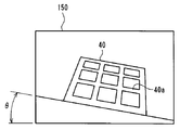
例えば、撮像装置1がロール方向に角度θだけ傾斜して配置される場合には、図12に示すように、1次画像データ150中において被写体の水平方向及び垂直方向と、1次画像データ150の座標軸であるx軸及びy軸とが一致しない。この場合の1次画像データ150にピッチ方向及びヨー方向の台形補正処理を実施しても、使用者が所望する台形補正が施された2次画像データが得られない場合がある。
そこで、本実施形態の撮像装置1は、台形補正処理を実施する前の1次画像データ150に対して回転補正処理を実行し、被写体の水平方向及び垂直方向と画像データ中のx軸及びy軸とを一致させる。
図11は、本実施形態の撮像装置1における台形補正処理のフローチャートである。台形補正処理では、まず、ステップS131では、第1の実施形態のステップS31と同様の動作を行う。すなわち、撮像レンズ4の撮像レンズ4の焦点距離fの値を取得し、RAM12のログ情報バッファ12cに記憶する。
次に、ステップS132において、ロール方向の補正角度である第3角度αθの値を取得し、RAM12のログ情報バッファ12cに記憶する。第3角度αθの値は、前述のように、使用者によって入力部7を介して入力される。
次に、ステップS133において、回転補正部16cによって、第3角度αθの値に応じて、1次画像データに対して水平軸(X軸)と垂直軸(Y軸)を回転座標変換する回転補正処理を行う。ステップS133の実行によって、回転補正処理された2次画像データを取得する。
回転座標変換の演算処理手段は、下記数式(3)に基づいた1次変換処理を用いた回転座標変換処理を用いる。下記数式(3)は、1次画像データ150の座標(x,y)と、1次画像データ150に対してロール方向に角度θだけ回転した2次画像データ150’の座標(x’,y’)との関係を表す式である。
[数3]
x’=x・cosθ-y・sinθ
y’=x・sinθ+y・cosθ
回転補正処理によって得られた2次画像データ150’中では、図13のように、被写体である建築物40の傾きが補正される。
x’=x・cosθ-y・sinθ
y’=x・sinθ+y・cosθ
回転補正処理によって得られた2次画像データ150’中では、図13のように、被写体である建築物40の傾きが補正される。
次に、ステップS134において、第1の実施形態のステップS32と同様の動作を行う。すなわち、ピッチ方向及びヨー方向の補正角度である、第1角度αy及び第2角度αxの値を取得し、RAM12のログ情報バッファ12cに記憶する。
そして、ステップS135では、第1の実施形態のステップS33と同様の動作を行う。すなわち、ログ情報バッファ12cに記憶されている焦点距離fの値と第1角度αy及び第2角度αxの値を用いて、ステップS133の実行によって得られた2次画像データ150’に台形補正処理を施した2次画像データ150”を生成する。2次画像データ150”中では、図14のように、被写体である建築物40の台形歪みが補正される。
なお、本実施形態では、1次画像データに対する回転補正処理を、画像処理部16で行う手段を示した。しかしながら回転補正処理の手段は、本実施形態に限られるものではなく、例えば撮像装置1内に、撮像素子3をロール方向に回動させる回動機構を設置し、撮像素子3を第3角度αθの値に応じて回動することによっても、回転補正処理を行うことができる。
本実施形態に係る撮像装置によれば、台形補正処理を行う前に、回転補正処理を行って、被写体像の水平または垂直方向を、台形補正に係るヨー方向、ピッチ方向に対応した状態にすることができる。この作用によって、撮影構図として、被写体の水平方向と撮像装置の水平方向とを一致させられない場合であっても、撮影者の所望通りの台形補正を施した撮影画像を取得することが可能になる。
なお、本発明は、上述した実施形態に限られるものではなく、特許請求の範囲及び明細書全体から読み取れる発明の要旨或いは思想に反しない範囲で適宜変更可能であり、そのような変更を伴う撮像装置及び撮像装置の表示方法もまた本発明の技術的範囲に含まれるものである。
また、本発明に係る撮像装置は、上述の実施形態で説明したような、デジタルカメラの形態に限らず、例えば撮像機能を備えた電子機器の形態であってもよい。撮像機能を備えた電子機器としては、例えば携帯通信端末、ゲーム機、デジタルメディアプレーヤー、腕時計、ボイスレコーダー、双眼鏡等が考えられる。
本出願は、2015年1月16日に日本国に出願された特願2015-6977号を優先権主張の基礎として出願するものであり、上記の開示内容は、本願明細書、請求の範囲、図面に引用されたものとする。
Claims (4)
- 撮像レンズの光軸に受光面が直交するように配置され、所定のフレーム周期毎に1次画像データを取得する撮像素子と、
前記フレーム周期に同期して前記撮像レンズの焦点距離である第1の焦点距離を取得する焦点距離検出部と、
前記受光面に対してピッチ方向になす角度である第1角度、及び前記受光面に対してヨー方向になす角度である第2角度からなる2つの値を含む補正角度を入力する構成を有する入力装置と、
前記フレーム周期に同期して、前記第1の焦点距離の値及び前記補正角度の値を用い、前記1次画像データを、前記受光面に対してピッチ方向に前記第1角度をなし、前記受光面に対してヨー方向に前記第2角度をなす平面上に投影する変形処理を施した2次画像データを生成する画像処理部と、
前記フレーム周期に同期して、前記2次画像データに基づく画像を表示する画像表示装置と、
を備えることを特徴とする撮像装置。 - 前記入力装置は、前記撮像レンズの光軸周りの角度である第3角度の値を補正するための回転補正角度を入力する構成を更に有しており、
前記画像処理部は、前記フレーム周期に同期して、前記第1の焦点距離の値及び前記補正角度の値を用いて、前記1次画像データを、ロール方向へ回転する回転変形処理を施した2次画像データを生成する回転補正処理手段を更に有する
ことを特徴とする請求項1に記載の撮像装置。 - 前記入力装置は、任意の値である第2の焦点距離を入力する構成と、
前記焦点距離検出部が取得した前記第1の焦点距離と、前記第2の焦点距離のどちらか1つを選択する構成と、を更に有しており、
前記画像処理部は、前記入力装置によって選択された前記第1の焦点距離又は前記第2の焦点距離の値と、前記補正角度の値とを用い、前記1次画像データを、前記受光面に対してピッチ方向に前記第1角度をなし、前記受光面に対してヨー方向に前記第2角度をなす平面上に投影する変形処理を施した2次画像データを生成する
ことを特徴とする請求項1又は2に記載の撮像装置。 - 撮像レンズの光軸に受光面が直交するように配置され、所定のフレーム周期毎に1次画像データを取得する撮像素子と、
前記フレーム周期に同期して前記撮像レンズの焦点距離を取得する焦点距離検出部と、
前記光軸に対してピッチ方向になす角度である第1角度、及び前記光軸に対してヨー方向になす角度である第2角度からなる2つの値を含む補正角度を入力する入力装置と、
画像表示装置と
を備える撮像装置の表示方法であって、
前記フレーム周期に同期して、前記焦点距離の値及び前記補正角度の値を用い、前記1次画像データを、前記光軸に対してピッチ方向に前記第1角度をなし、前記光軸に対してヨー方向に前記第2角度をなす平面上に投影する変形処理を施した2次画像データを生成するステップと、
前記フレーム周期に同期して、前記2次画像データに基づく画像を前記画像表示装置に表示するステップと、
を含むことを特徴とする撮像装置の表示方法。
Applications Claiming Priority (2)
| Application Number | Priority Date | Filing Date | Title |
|---|---|---|---|
| JP2015006977A JP2016134685A (ja) | 2015-01-16 | 2015-01-16 | 撮像装置及び撮像装置の表示方法 |
| JP2015-006977 | 2015-01-16 |
Publications (1)
| Publication Number | Publication Date |
|---|---|
| WO2016113997A1 true WO2016113997A1 (ja) | 2016-07-21 |
Family
ID=56405554
Family Applications (1)
| Application Number | Title | Priority Date | Filing Date |
|---|---|---|---|
| PCT/JP2015/082286 Ceased WO2016113997A1 (ja) | 2015-01-16 | 2015-11-17 | 撮像装置及び撮像装置の表示方法 |
Country Status (2)
| Country | Link |
|---|---|
| JP (1) | JP2016134685A (ja) |
| WO (1) | WO2016113997A1 (ja) |
Citations (6)
| Publication number | Priority date | Publication date | Assignee | Title |
|---|---|---|---|---|
| JPH10210354A (ja) * | 1997-01-27 | 1998-08-07 | Minolta Co Ltd | デジタルカメラ |
| JP2001134751A (ja) * | 1999-08-26 | 2001-05-18 | Ricoh Co Ltd | 画像処理方法及び装置、デジタルカメラ、画像処理システム、並びに、画像処理プログラムを記録した記録媒体 |
| JP2005122327A (ja) * | 2003-10-14 | 2005-05-12 | Casio Comput Co Ltd | 撮影装置、その画像処理方法及びプログラム |
| JP2005184089A (ja) * | 2003-12-16 | 2005-07-07 | Konica Minolta Opto Inc | 撮像装置 |
| JP2007096829A (ja) * | 2005-09-29 | 2007-04-12 | Matsushita Electric Ind Co Ltd | 撮像装置 |
| JP2008176768A (ja) * | 2006-12-19 | 2008-07-31 | Hitachi Kokusai Electric Inc | 画像処理装置 |
-
2015
- 2015-01-16 JP JP2015006977A patent/JP2016134685A/ja active Pending
- 2015-11-17 WO PCT/JP2015/082286 patent/WO2016113997A1/ja not_active Ceased
Patent Citations (6)
| Publication number | Priority date | Publication date | Assignee | Title |
|---|---|---|---|---|
| JPH10210354A (ja) * | 1997-01-27 | 1998-08-07 | Minolta Co Ltd | デジタルカメラ |
| JP2001134751A (ja) * | 1999-08-26 | 2001-05-18 | Ricoh Co Ltd | 画像処理方法及び装置、デジタルカメラ、画像処理システム、並びに、画像処理プログラムを記録した記録媒体 |
| JP2005122327A (ja) * | 2003-10-14 | 2005-05-12 | Casio Comput Co Ltd | 撮影装置、その画像処理方法及びプログラム |
| JP2005184089A (ja) * | 2003-12-16 | 2005-07-07 | Konica Minolta Opto Inc | 撮像装置 |
| JP2007096829A (ja) * | 2005-09-29 | 2007-04-12 | Matsushita Electric Ind Co Ltd | 撮像装置 |
| JP2008176768A (ja) * | 2006-12-19 | 2008-07-31 | Hitachi Kokusai Electric Inc | 画像処理装置 |
Also Published As
| Publication number | Publication date |
|---|---|
| JP2016134685A (ja) | 2016-07-25 |
Similar Documents
| Publication | Publication Date | Title |
|---|---|---|
| US9774782B2 (en) | Image pickup apparatus and image pickup method | |
| JP7030442B2 (ja) | 画像処理装置、画像処理方法、及びプログラム | |
| JP6518409B2 (ja) | 撮影装置及び撮影方法 | |
| CN103139472B (zh) | 数字拍摄设备及其控制方法 | |
| JP6312460B2 (ja) | 撮像装置、撮像装置の制御方法、プログラム、および、記憶媒体 | |
| CN103636187B (zh) | 摄像装置 | |
| JP7163057B2 (ja) | 撮像装置、撮像方法、プログラムおよび記録媒体 | |
| US20200021745A1 (en) | Imaging apparatus | |
| JP2016134686A (ja) | 撮像装置及び撮像方法 | |
| JP2020034759A (ja) | 撮像装置及びその制御方法、並びにプログラム | |
| JP6300569B2 (ja) | 撮像装置及びその制御方法 | |
| JP6395156B2 (ja) | 撮像装置及び撮像方法 | |
| JP6494060B2 (ja) | 情報処理装置、情報処理方法、及びプログラム | |
| JP6376753B2 (ja) | 撮像装置、表示制御装置の制御方法、記録装置の制御方法 | |
| WO2016113997A1 (ja) | 撮像装置及び撮像装置の表示方法 | |
| JP2017011657A (ja) | 撮像装置 | |
| JP6456093B2 (ja) | 撮像装置、および、撮像装置の制御方法 | |
| JP7051586B2 (ja) | 撮像装置、撮像方法およびプログラム | |
| JP6218615B2 (ja) | 表示機器、表示方法、撮影装置及び撮影システム | |
| JP2012060552A (ja) | カメラおよび電子機器 | |
| JP2017055268A (ja) | 撮像装置、撮像装置の制御方法及びプログラム | |
| JP2014165517A (ja) | 撮像装置及びその制御方法 | |
| JP2021021804A (ja) | 撮像装置 | |
| JP5775620B2 (ja) | 画像処理装置、撮像装置、制御方法及びプログラム | |
| JP2016208204A (ja) | 画像撮影方法および画像撮影装置、プログラム |
Legal Events
| Date | Code | Title | Description |
|---|---|---|---|
| 121 | Ep: the epo has been informed by wipo that ep was designated in this application |
Ref document number: 15877949 Country of ref document: EP Kind code of ref document: A1 |
|
| NENP | Non-entry into the national phase |
Ref country code: DE |
|
| 122 | Ep: pct application non-entry in european phase |
Ref document number: 15877949 Country of ref document: EP Kind code of ref document: A1 |