WO2016111191A1 - 真空遮断器 - Google Patents
真空遮断器 Download PDFInfo
- Publication number
- WO2016111191A1 WO2016111191A1 PCT/JP2015/086157 JP2015086157W WO2016111191A1 WO 2016111191 A1 WO2016111191 A1 WO 2016111191A1 JP 2015086157 W JP2015086157 W JP 2015086157W WO 2016111191 A1 WO2016111191 A1 WO 2016111191A1
- Authority
- WO
- WIPO (PCT)
- Prior art keywords
- vacuum
- vacuum interrupter
- link mechanism
- bellows
- circuit breaker
- Prior art date
- Legal status (The legal status is an assumption and is not a legal conclusion. Google has not performed a legal analysis and makes no representation as to the accuracy of the status listed.)
- Ceased
Links
Images

Classifications
-
- H—ELECTRICITY
- H01—ELECTRIC ELEMENTS
- H01H—ELECTRIC SWITCHES; RELAYS; SELECTORS; EMERGENCY PROTECTIVE DEVICES
- H01H33/00—High-tension or heavy-current switches with arc-extinguishing or arc-preventing means
- H01H33/60—Switches wherein the means for extinguishing or preventing the arc do not include separate means for obtaining or increasing flow of arc-extinguishing fluid
- H01H33/66—Vacuum switches
- H01H33/662—Housings or protective screens
- H01H33/66238—Specific bellows details
-
- H—ELECTRICITY
- H01—ELECTRIC ELEMENTS
- H01H—ELECTRIC SWITCHES; RELAYS; SELECTORS; EMERGENCY PROTECTIVE DEVICES
- H01H33/00—High-tension or heavy-current switches with arc-extinguishing or arc-preventing means
- H01H33/60—Switches wherein the means for extinguishing or preventing the arc do not include separate means for obtaining or increasing flow of arc-extinguishing fluid
- H01H33/66—Vacuum switches
- H01H33/662—Housings or protective screens
-
- H—ELECTRICITY
- H01—ELECTRIC ELEMENTS
- H01H—ELECTRIC SWITCHES; RELAYS; SELECTORS; EMERGENCY PROTECTIVE DEVICES
- H01H33/00—High-tension or heavy-current switches with arc-extinguishing or arc-preventing means
- H01H33/60—Switches wherein the means for extinguishing or preventing the arc do not include separate means for obtaining or increasing flow of arc-extinguishing fluid
- H01H33/66—Vacuum switches
- H01H33/666—Operating arrangements
-
- H—ELECTRICITY
- H01—ELECTRIC ELEMENTS
- H01H—ELECTRIC SWITCHES; RELAYS; SELECTORS; EMERGENCY PROTECTIVE DEVICES
- H01H33/00—High-tension or heavy-current switches with arc-extinguishing or arc-preventing means
- H01H33/02—Details
- H01H33/53—Cases; Reservoirs, tanks, piping or valves, for arc-extinguishing fluid; Accessories therefor, e.g. safety arrangements, pressure relief devices
- H01H33/56—Gas reservoirs
- H01H2033/566—Avoiding the use of SF6
-
- H—ELECTRICITY
- H01—ELECTRIC ELEMENTS
- H01H—ELECTRIC SWITCHES; RELAYS; SELECTORS; EMERGENCY PROTECTIVE DEVICES
- H01H33/00—High-tension or heavy-current switches with arc-extinguishing or arc-preventing means
- H01H33/02—Details
- H01H33/04—Means for extinguishing or preventing arc between current-carrying parts
- H01H33/14—Multiple main contacts for the purpose of dividing the current through, or potential drop along, the arc
Definitions
- the present invention relates to a vacuum circuit breaker, and more particularly to an internal pressure structure of a two-point vacuum circuit breaker.
- the vacuum circuit breaker is widely applied in the power system mainly in the middle voltage class of 84 kV or less.
- the vacuum circuit breaker has a long life of the circuit breaker and has a high global warming potential gas (for example, SF 6 gas) compared to other circuit breakers (for example, a gas circuit breaker (GCB)).
- SF 6 gas global warming potential gas
- GCB gas circuit breaker
- the tank type circuit breaker has a vacuum interrupter (VI) covered with a grounding layer and has a low center of gravity. Compared with a conventional insulator type circuit breaker, it is possible to attach a current transformer and improve earthquake resistance. It has an advantage such as.
- Non-Patent Document 1 With respect to the higher voltage of the vacuum circuit breaker, the withstand voltage is improved by connecting two vacuum interrupters as a breaker in series.
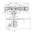
- FIG. 4 is a front longitudinal sectional view of a vacuum circuit breaker 35 according to the prior art.
- the vacuum circuit breaker 35 includes a ground tank 2, a vacuum interrupter 3 and a vacuum interrupter 4 housed in the ground tank 2, and a link mechanism 5 that opens and closes the vacuum interrupters 3 and 4.
- the ground tank 2 is a cylindrical metal container and houses the vacuum interrupters 3 and 4 and the link mechanism 5.
- the ground tank 2 is filled with an insulating gas such as SF 6 gas.
- the vacuum interrupter 3 is configured by housing a pair of electrodes (a fixed electrode 7 and a movable electrode 8) in a vacuum vessel 6 composed of an insulating cylinder and a metal flange.
- An intermediate shield 9 is provided in the vacuum vessel 6 so as to cover the fixed electrode 7 and the movable electrode 8.
- the fixed electrode 7 is fixed to one end of the fixed lead 3a.
- the other end of the fixed lead 3 a extends from the end surface of the vacuum vessel 6 and is fixed to the support insulator 10.
- a conductor 12 is connected to the other end of the fixed lead 3a through a conductor fitting 11.
- the movable electrode 8 is fixed to one end of the movable lead 3b.
- the other end of the movable lead 3 b extends from the end surface of the vacuum vessel 6 and is connected to the link mechanism 5.
- the bellows 13 is provided in the insertion part of the movable lead 3b in the vacuum vessel 6, and the movable lead 3b can move in the axial direction while keeping the inside of the vacuum vessel 6 in a vacuum.
- a voltage dividing capacitor 14 is provided in parallel with the vacuum interrupter 3.
- the vacuum interrupter 4 has the same configuration as the vacuum interrupter 3. That is, the vacuum interrupter 4 is configured by housing a pair of electrodes (a fixed electrode 7 and a movable electrode 8) in a vacuum vessel 6.
- the fixed electrode 7 is fixed to one end of the fixed lead 4 a, and the other end of the fixed lead 4 a is fixed to the support insulator 15. Further, a conductor 17 is connected to the other end of the fixed lead 4a through a conductor fitting 16.
- the movable electrode 8 is fixed to one end of the movable lead 4b. The other end of the movable lead 4 b extends from the end surface of the vacuum vessel 6 and is connected to the link mechanism 5.
- a voltage dividing capacitor 18 is provided in parallel with the vacuum interrupter 4.
- the link mechanism 5 includes a link 5a, a link 5b, and a link 5c.
- the link mechanism 5 is housed in the link mechanism case 36.
- One end of the link 5a is rotatably supported in the link mechanism case 36, and the other end of the link 5a is rotatably supported by the movable lead 3b.
- one end of the link 5c is rotatably provided on the link 5a, and the other end of the link 5c is rotatably supported by one end of the insulating operation rod 20 for opening and closing the vacuum interrupters 3 and 4.
- one end of the link 5b is rotatably supported in the link mechanism case 36, and the other end of the link 5b is rotatably supported by the movable lead 4b.
- One end of the link 5c is rotatably supported by the link 5b, and the end of the link 5c is rotatably supported by one end of the insulating operation rod 20.
- the link mechanism case 36 houses the link mechanism 5 and electrically connects the movable lead 3b and the movable lead 4b.
- the link mechanism case 36 includes a movable side end of the vacuum interrupter 3 (that is, the end of the vacuum interrupter 3 from which the movable lead 3b projects) and a movable side end of the vacuum interrupter 4 (that is, the vacuum interrupter from which the movable lead 4b projects). 4 end portions).
- the link mechanism case 36 is supported by the support rod 21 provided on the inner peripheral surface of the ground tank 2.
- the insulating operation rod 20 is provided through the side of the link mechanism case 36, the support rod 21 and the ground tank 2.
- An operation chamber 23 is provided on the outer periphery of the ground tank 2 and in the insertion portion of the insulating operation rod 20.
- the operation room 23 houses the conversion mechanism 24.
- the conversion mechanism 24 converts the rotation operation of the rotary shaft 25 into a linear motion of the insulating operation rod 20.
- One end of the rotary shaft 25 is exposed to the outside of the operation chamber 23 through the rotary seal portion 26, and an operation mechanism (not shown) for operating the insulating operation rod 20 outside the operation chamber 23 and the like.
- the drive unit 27 for driving the insulating operation rod of the first phase is connected to the rotary shaft 25.
- the vacuum circuit breaker 35 in order to insulate the high-voltage conductors 12 and 17, the fixed-side end portions and the movable-side end portions of the vacuum interrupters 3 and 4 and the link mechanism case 36 from the ground tank 2 which is the ground potential Insulating gas is sealed in the ground tank 2, the link mechanism case 36, the support rod 21 and the operation chamber 23.
- the insulating gas for example, SF 6 gas of about 0.25 MPa is used. Since SF 6 gas is excellent in insulation performance, the gas pressure can be handled at a low pressure. Since the vacuum circuit breaker 35 has a structure in which the vacuum interrupters 3 and 4 as the circuit breaker are connected in series at two points, the withstand voltage is high, and the vacuum circuit breaker 35 can be increased in voltage.
- the making operation is performed by moving the insulating operation rod 20 in the direction toward the inside of the ground tank 2 (upward in the figure) by the rotation of a lever (not shown) connected to the drive unit 27 in accordance with the making command. That is, the link 5c connected to the link 5a is raised while turning right according to the movement of the insulating operation rod 20. In accordance with the movement of the link 5c, the link 5a moves the movable lead 3b in the direction of the vacuum interrupter 3 along the axis. As a result, the fixed electrode 7 and the movable electrode 8 of the vacuum interrupter 3 are connected. Similarly, in accordance with the movement of the insulating operation rod 20, the link 5c connected to the link 5b rises while turning counterclockwise. In response to the movement of the link 5c, the link 5b moves the movable lead 4b along the axis in the direction of the vacuum interrupter 4, and the fixed electrode 7 and the movable electrode 8 of the vacuum interrupter 4 are connected.
- shut-off operation is performed by moving the insulating operation rod 20 in the outward direction of the ground tank 2 (downward in the figure). That is, by the reverse operation to the closing operation, the movable lead 3b moves along the axis in the direction away from the vacuum interrupter 3, and the fixed electrode 7 and the movable electrode 8 of the vacuum interrupter 3 are separated. Similarly, the movable lead 4b moves along the axis in a direction away from the vacuum interrupter 4, and the fixed electrode 7 and the movable electrode 8 of the vacuum interrupter 4 are separated from each other.
- the vacuum inside the vacuum container 6 is maintained by the bellows 13 which can be expanded and contracted even when the movable leads 3 b and 4 b move during the turning on and off.
- the bellows 13 has a structure that can withstand to some extent the pressure difference between the vacuum on the outer peripheral side and the insulating gas (for example, SF 6 gas) on the inner peripheral side.
- the bellows is made of a thin metal such as stainless steel, and when the differential pressure becomes larger than a certain level, a phenomenon called buckling occurs. Therefore, the pressure of the insulating gas sealed on the inner peripheral side of the bellows must be at least about 0.3 MPa or less.
- the pressure of the insulating gas sealed in the vacuum circuit breaker will be increased and the insulation performance of the vacuum circuit breaker will be improved.
- One of the weakest points is the vacuum interrupter bellows.
- Non-Patent Document 2 measures such as making the bellows have a structure that can withstand the pressure difference between the inside and outside (for example, an external pressure bellows) have been taken (for example, Non-Patent Document 2).
- the material and structure of the bellows used in the high pressure resistant vacuum interrupter is special, which causes an increase in the cost of the vacuum circuit breaker.
- the bellows is an external pressure type, the bellows portion may be increased in size, or the heat dissipation of the vacuum interrupter may be reduced.
- This invention aims at providing the technique which contributes to the high voltage of a 2 point cut vacuum circuit breaker.
- the vacuum circuit breaker of the present invention that achieves the above object is a vacuum vessel composed of an insulating cylinder and a metal flange, a fixed electrode and a movable electrode housed in the vacuum vessel, and the movable electrode can be attached to and detached from the fixed electrode.
- a first vacuum interrupter and a second vacuum interrupter having a movable lead to be supported; and a bellows provided in the movable lead insertion portion in the vacuum vessel; and a ground tank for storing the first vacuum interrupter and the second vacuum interrupter.
- a link mechanism provided in the grounding tank for moving the movable lead of the first vacuum interrupter and the movable lead of the second vacuum interrupter in the axial direction, a link mechanism case for housing the link mechanism, and provided on the inner peripheral surface of the grounding tank.
- a vacuum circuit breaker having a supporting rod supporting the link mechanism case and an insulating operation rod for operating the link mechanism, The movable lead of the first vacuum interrupter is inserted into the structure case, the inside of the link mechanism case and the space of the inner periphery of the bellows of the first vacuum interrupter are communicated with each other at the insertion portion of the movable lead, and the second vacuum interrupter is connected to the link mechanism case.
- the movable lead is inserted, the inside of the link mechanism case and the space of the inner periphery of the bellows of the second vacuum interrupter are communicated with each other at the insertion portion of the movable lead, and the insulating operation rod is connected to the inside of the support rod pipe and the side of the ground tank.
- a space communicating with the inner peripheral portion of the bellows of the second vacuum interrupter is filled with an insulating gas of 0.3 MPa or less, and the first vacuum is placed in the outer periphery of the link mechanism case and the outer periphery of the support pipe in the ground tank.
- a high-pressure insulating gas is filled in a space communicating with the inner peripheral portion of the bellows of the interrupter and the inner peripheral portion of the bellows of the second vacuum interrupter.
- a vacuum circuit breaker according to an embodiment of the present invention will be described with reference to the drawings.
- the drawings are schematic views of a vacuum circuit breaker according to an embodiment of the present invention, and the dimensions of each component are exaggerated for explanation.
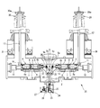
- FIG. 1 is a front longitudinal sectional view of a vacuum circuit breaker 1 according to an embodiment of the present invention.
- the vacuum circuit breaker 1 includes a ground tank 2, a vacuum interrupter 3 and a vacuum interrupter 4 housed in the ground tank 2, and a link mechanism 5 that opens and closes the vacuum interrupters 3 and 4.
- the ground tank 2 is a cylindrical metal container and houses the vacuum interrupters 3 and 4 and the link mechanism 5.
- the ground tank 2 is filled with an insulating gas such as SF 6 gas.
- the vacuum interrupter 3 is configured by housing a pair of electrodes (a fixed electrode 7 and a movable electrode 8) in a vacuum vessel 6 composed of an insulating cylinder and a metal flange.
- An intermediate shield 9 is provided in the vacuum vessel 6 so as to cover the fixed electrode 7 and the movable electrode 8.
- the fixed electrode 7 is fixed to one end of the fixed lead 3a.
- the other end of the fixed lead 3 a extends from the end surface of the vacuum vessel 6 and is fixed to the support insulator 10.
- a conductor 12 is connected to the other end of the fixed lead 3a through a conductor fitting 11.
- the movable electrode 8 is fixed to one end of the movable lead 3b.
- the other end of the movable lead 3 b extends from the end surface of the vacuum vessel 6 and is connected to the link mechanism 5.
- the bellows 13 is provided in the insertion part of the movable lead 3b in the vacuum vessel 6, and the movable lead 3b can move in the axial direction while keeping the inside of the vacuum vessel 6 in a vacuum.
- a voltage dividing capacitor 14 is provided in parallel with the vacuum interrupter 3.
- the vacuum interrupter 4 has the same configuration as the vacuum interrupter 3. That is, the vacuum interrupter 4 is configured by housing a pair of electrodes (a fixed electrode 7 and a movable electrode 8) in a vacuum vessel 6.
- the fixed electrode 7 is fixed to one end of the fixed lead 4 a, and the other end of the fixed lead 4 a is fixed to the support insulator 15. Further, a conductor 17 is connected to the other end of the fixed lead 4a through a conductor fitting 16.
- the movable electrode 8 is fixed to one end of the movable lead 4b. The other end of the movable lead 4 b extends from the end surface of the vacuum vessel 6 and is connected to the link mechanism 5.
- a voltage dividing capacitor 18 is provided in parallel with the vacuum interrupter 4.
- the link mechanism 5 includes a link 5a, a link 5b, and a link 5c.
- the link mechanism 5 is housed in the link mechanism case 19.
- One end of the link 5a is rotatably supported in the link mechanism case 19, and the other end of the link 5a is rotatably connected to the movable lead 3b.
- one end of the link 5c is rotatably provided on the link 5a, and the other end of the link 5c is rotatably supported by one end of the insulating operation rod 20 for opening and closing the vacuum interrupters 3 and 4.
- one end of the link 5b is rotatably supported in the link mechanism case 19, and the other end of the link 5b is rotatably connected to the movable lead 4b.
- one end of the link 5c is rotatably supported by the link 5b, and the other end of the link 5c is rotatably supported by one end of the insulating operation rod 20.
- the link mechanism case 19 houses the link mechanism 5 and electrically connects the movable lead 3b and the movable lead 4b.
- the link mechanism case 19 includes a movable end of the vacuum interrupter 3 (that is, the end of the vacuum interrupter 3 from which the movable lead 3b protrudes) and a movable end of the vacuum interrupter 4 (that is, the vacuum interrupter from which the movable lead 4b protrudes). 4 end portions).
- the link mechanism case 19 is supported by a support rod 21 provided on the inner peripheral surface of the ground tank 2.
- the link mechanism case 19 and the movable side end 3c of the vacuum interrupter 3 are hermetically connected by a packing (not shown) such as an O-ring.
- the link mechanism case 19 is provided with the movable lead 3b inserted therethrough, and the inner peripheral portion of the bellows 13 of the vacuum interrupter 3 communicates with the inside of the link mechanism case 19 through the insertion portion 19a of the movable lead 3b of the link mechanism case 19.
- the insertion portion 19a is provided with a connection portion 22 such as a ring contact, and the movable lead 3b and the link mechanism case 19 are electrically connected.
- the link mechanism case 19 and the movable end 4c of the vacuum interrupter 4 are hermetically connected by a packing (not shown) such as an O-ring.
- the link mechanism case 19 is provided with the movable lead 4b inserted therethrough, and the inner periphery of the bellows 13 of the vacuum interrupter 4 and the inside of the link mechanism case 19 communicate with each other through the insertion portion 19b of the movable lead 4b of the link mechanism case 19. .
- the insertion portion 19b is provided with a connection portion 22 such as a ring contact, and the movable lead 4b and the link mechanism case 19 are electrically connected.
- a manhole 19 c for providing the link mechanism 5 in the link mechanism case 19 is formed at the upper part of the link mechanism case 19. The manhole 19c is sealed with a sealing member 19d.
- the support rod 21 is provided in the inner periphery of the ground tank 2 and supports the link mechanism case 19.
- the connection portion between the support rod tube 21 and the link mechanism case 19 and the connection portion between the support rod tube 21 and the ground tank 2 are airtightly provided by packing such as an O-ring.
- the insulating operation rod 20 is provided through the side of the link mechanism case 19, the supporting rod 21 and the ground tank 2.
- An operation chamber 23 is provided in the outer peripheral portion of the ground tank 2 and in the insertion portion of the insulating operation rod 20.
- the operation chamber 23 is airtightly provided on the outer periphery of the ground tank 2 by packing such as an O-ring.
- a conversion mechanism 24 is accommodated in the operation chamber 23.
- the conversion mechanism 24 converts the rotation operation of the rotation shaft (rotation drive shaft) 25 into a linear motion of the insulating operation rod 20.
- One end of the rotary shaft 25 is exposed to the outside of the operation chamber 23 via a rotation seal portion 26 (for example, a rotary seal case sealed with hydraulic packing such as SKY packing).
- An operating mechanism (not shown) for operating the insulating operating rod 20 and a drive unit 27 for driving an insulating operating rod of another phase are connected to the rotary shaft 25.
- the operation chamber 23 is provided with a pressure gauge for monitoring the internal pressure, a valve for adjusting the internal pressure, and the like.
- the conductor 12 is provided in a state protruding from the ground tank 2, and a bushing 28 is provided around the conductor 12.
- the bushing 28 is supported by the ground tank 2.
- a bushing terminal 28 a that is electrically connected to the conductor 12 is provided at the upper end portion of the bushing 28, and a bushing current transformer 29 is provided at a connection portion between the bushing 28 and the ground tank 2.
- the conductor 17 is provided in a state protruding from the ground tank 2, and a bushing 30 is provided around the conductor 17.
- the bushing 30 is supported by the ground tank 2.
- a bushing terminal 30 a that is electrically connected to the conductor 17 is provided at the upper end portion of the bushing 30, and a bushing current transformer 31 is provided at a connection portion between the bushing 30 and the ground tank 2.
- This space is filled with an insulating gas of 0.3 MPa or less (for example, SF 6 gas of 0.25 MPa). That is, the hatched portion in FIG. 1 is a portion filled with a low-pressure insulating gas.
- a high-pressure insulating gas for example, a space on the inner peripheral side of the bellows 13 of the vacuum interrupter 3 or a space on the inner peripheral portion of the bellows 13 of the vacuum interrupter 4 is higher.
- SF 6 gas is filled.
- a low-pressure side space (a space communicating with the inner peripheral portion of the bellows 13 of the vacuum interrupter 3 and a space communicating with the inner peripheral portion of the bellows 13 of the vacuum interrupter 4) and a high-pressure side space (the communication with the inner peripheral portion of the bellows 13).
- an insulating gas such as dry air, nitrogen gas (N 2 ), and carbon dioxide gas (CO 2 ) is filled in the space.
- the insulating gas filled in the low pressure side space portion and the high pressure side space portion be the same type of gas because the maintenance and management of the vacuum circuit breaker 1 is facilitated.
- the insulation performance of the high pressure side space portion increases as the pressure of the SF 6 gas filled in the high pressure side space portion increases.
- the vacuum circuit breaker 1 can be made smaller.
- the insulation performance which is lower than that of SF 6 gas, is compensated by increasing the pressure of the dry air filling the high-pressure side space. be able to. In this case, the decrease in the insulation performance in the low-pressure space is compensated by a method such as increasing the distance.
- the obtained vacuum circuit breaker 1 can be obtained.
- the low pressure side space is filled with SF 6 gas and the high pressure side space is filled with dry air, the use of the SF 6 gas can be suppressed, and the vacuum circuit breaker 1 with reduced size can be obtained. .
- the closing / breaking operation of the vacuum circuit breaker 1 is performed by operating the link mechanism 5 by the insulating operation rod 20. Since the rotation seal portion 26 is provided in the rotating shaft 17 insertion portion of the operation chamber 23 of the vacuum circuit breaker 1, the pressure in the operation chamber 23 (that is, the pressure in the inner peripheral portion of the bellows 13) is 0.3 MPa or less.
- the insulation operation rod 20 is operated in a state where the pressure is kept low, and the vacuum circuit breaker 1 is turned on (or cut off).
- the closing operation of the vacuum circuit breaker 1 by the link mechanism 5 is performed by moving the insulating operation rod 20 in the direction toward the inside of the ground tank 2 (upward in the figure). That is, the link 5c connected to the link 5a is raised while turning right according to the movement of the insulating operation rod 20.
- the link 5a moves the movable lead 3b in the direction of the vacuum interrupter 3 along the axis.
- the fixed electrode 7 and the movable electrode 8 of the vacuum interrupter 3 are connected.
- the link 5c connected to the link 5b rises while turning counterclockwise.
- the link 5b moves the movable lead 4b along the axis in the direction of the vacuum interrupter 4, and the fixed electrode 7 and the movable electrode 8 of the vacuum interrupter 4 are connected.
- the breaking operation of the vacuum circuit breaker 1 by the link mechanism 5 is performed when the insulating operation rod 20 moves in the outward direction of the ground tank 2 (downward in the figure). That is, by the reverse operation to the closing operation, the movable lead 3b moves along the axis in the direction away from the vacuum interrupter 3, and the fixed electrode 7 and the movable electrode 8 of the vacuum interrupter 3 are separated. Similarly, the movable lead 4b moves along the axis in a direction away from the vacuum interrupter 4, and the fixed electrode 7 and the movable electrode 8 of the vacuum interrupter 4 are separated from each other.
- the pressure of the insulating gas filled in the inner peripheral part of the bellows 13 of the vacuum interrupter 3 and the inner peripheral part of the bellows 13 of the vacuum interrupter 4 is set to 0.3 MPa.
- the internal / external pressure difference of the bellows 13 can be reduced and damage to the bellows 13 can be suppressed.
- the pressure of the insulating gas with which the space (for example, the space in the grounding tank 2 and the outer peripheral side of the link mechanism case 19 and the outer peripheral side of the support rod 21) that is not in communication with the inner peripheral portion of the bellows 13 is increased.
- the insulation performance of the vacuum circuit breaker 1 is improved, which contributes to a higher voltage of the vacuum circuit breaker 1.
- dry air of about 0.6 MPa is used. Therefore, the pressure of the insulating gas filled in the space not communicating with the inner peripheral portion of the bellows 13 is higher than the pressure of the space communicating with the inner peripheral portion of the bellows 13, more preferably a pressure higher than 0.3 MPa, More preferably, by setting the pressure to 0.6 to 0.8 MPa, the insulating performance of the vacuum circuit breaker 1 can be improved without increasing the size of the vacuum circuit breaker 1.
- the 2-point vacuum circuit breaker has been used mainly in the middle voltage class in the past, and has not been studied so far for increasing the voltage.
- the insulation performance of the vacuum circuit breaker 1 can improve and the vacuum circuit breaker 1 can be made higher voltage.
- the vacuum circuit breaker 1 can be applied to a higher voltage class (for example, a class higher than 84 kV).
- a higher voltage class for example, a class higher than 84 kV.
- a vacuum circuit breaker having one vacuum interrupter there is a vacuum circuit breaker having a voltage class of 145 kV, so that it can be expanded to a voltage class of 300 kV or more as a two-point vacuum circuit breaker. It is done.
- SF 6 gas has a high global warming potential, it is required to suppress its use as much as possible in order to prevent global warming.
- N 2 nitrogen gas
- CO 2 carbon dioxide gas
- these alternative gases have poor insulation performance compared to SF 6 gas, it is necessary to increase the gas pressure to be filled to about 0.5 to 0.6 MPa to improve the insulation performance.
- the bellows 13 of the vacuum interrupter 3 may be damaged. That is, in the conventional vacuum circuit breaker 35 as shown in FIG.
- the vacuum circuit breaker 1 fills a space communicating with the inner peripheral portion of the bellows 13 with a low-pressure insulating gas, and is a space other than that that requires insulation.
- a structure filled with a high-pressure insulating gas so-called two-pressure chamber structure
- damage to the bellows 13 can be suppressed and the insulating performance of the vacuum circuit breaker 1 can be improved.
- an insulating gas having a high global warming potential can be used without impairing the insulating performance. It is suppressed. As a result, it can contribute to prevention of global warming.
- the bellows 13 does not need to have a structure capable of withstanding the pressure difference between inside and outside, can be made into a mass production structure, and the vacuum interrupters 3 and 4 can be made inexpensive. it can. Since such a general internal pressure type bellows can be used, an operating device having a small self-closing force and a small operating force can be used. That is, since a special high-pressure-resistant vacuum interrupter or the like is not used, the vacuum circuit breaker 1 can be manufactured at a low cost, and an increase in the size of the vacuum circuit breaker 1 can be suppressed.
- the end of the rotation shaft 25 of the conversion mechanism 24 that operates the insulating operation rod 20 is projected outside the operation chamber 23 through the rotation seal portion 26, whereby the rotation shaft 25 can be operated in an airtight manner. That is, by making the space where the insulating operation rod 20 is provided airtight at one place, the vacuum interrupters 3 and 4 are made airtight in the inner peripheral part of the bellows 13 of the vacuum interrupter 3 and the inner peripheral part of the bellows 13 of the vacuum interrupter 4. Can be opened and closed.
- vacuum circuit breaker of the present invention is not limited to the embodiment, and the design can be appropriately changed within a range not impairing the features of the invention, and the modified design belongs to the technical scope of the present invention.
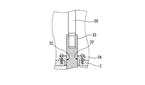
- a linear seal portion 32 as shown in FIG. 3 may be provided in the portion where the insulating operation rod 20 is inserted in the ground tank 2. More specifically, the linear seal portion 32 is formed by providing the ground-side metal fitting 33 at the ground tank 2 insertion portion of the insulation operation rod 20 and providing the housing 34 at the insulation operation rod 20 insertion portion of the ground tank 2. .
- the vacuum interrupters 3 and 4 are opened / closed, the insulating operation rod 20 operates in the internal direction or the external direction of the ground tank 2 while the outer peripheral portion of the ground side metal fitting 33 and the inner peripheral portion of the housing 34 are kept airtight. By sliding, the insulating operation rod 20 can be operated while the inside of the support rod 21 is kept airtight.
- the space filled with the low-pressure insulating gas is further narrowed, and in addition to the effects of the vacuum circuit breaker 1 of the embodiment. Further, the amount of the insulating gas filled in the space communicating with the inner peripheral portion of the bellows 13 can be further reduced.
- the vacuum circuit breaker 1 in which the movable lead 3b of the vacuum interrupter 3 and the movable lead 4b of the vacuum interrupter 4 are provided on the same axis is illustrated, but the movable lead 3b and the movable lead 4b are acute angles. It can also be applied to a vacuum circuit breaker that is arranged so that the movable lead 3b and the movable lead 4b are arranged in parallel.
Landscapes
- High-Tension Arc-Extinguishing Switches Without Spraying Means (AREA)
- Gas-Insulated Switchgears (AREA)
Abstract
Description
Claims (3)
- 絶縁筒と金属フランジで構成された真空容器と、真空容器内に収納される固定電極及び可動電極と、可動電極を固定電極に離接可能に支持する可動リードと、真空容器内であって可動リード挿通部に設けられるベローズと、を有する第1真空インタラプタ及び第2真空インタラプタと、
第1真空インタラプタ及び第2真空インタラプタを収納する接地タンクと、
接地タンク内に設けられ、第1真空インタラプタの可動リードと第2真空インタラプタの可動リードを軸方向に移動させるリンク機構と、
リンク機構を収納するリンク機構ケースと、
接地タンク内周面に設けられ、リンク機構ケースを支持する支持碍管と、
リンク機構に接続され、リンク機構の動作を行う絶縁操作棒と、を有する真空遮断器であって、
リンク機構ケースに第1真空インタラプタの可動リードを挿通し、この可動リードの挿通部においてリンク機構ケース内と第1真空インタラプタのベローズ内周部の空間とを連通させ、
リンク機構ケースに第2真空インタラプタの可動リードを挿通し、この可動リードの挿通部においてリンク機構ケース内と第2真空インタラプタのベローズ内周部の空間とを連通させ、
絶縁操作棒を支持碍管の管内及び接地タンクの側部を挿通して設け、
第1真空インタラプタのベローズ内周部の空間、第2真空インタラプタのベローズ内周部の空間、リンク機構ケース内及び支持碍管内を連通した空間とし、この空間を接地タンク内周部であってリンク機構ケース外周部及び支持碍管外周部の空間に対して気密とし、
前記第1真空インタラプタのベローズ内周部及び第2真空インタラプタのベローズ内周部と連通した空間に0.3MPa以下の絶縁ガスを充填し、接地タンク内であってリンク機構ケース外周部及び支持碍管外周部の空間に、前記第1真空インタラプタのベローズ内周部及び第2真空インタラプタのベローズ内周部と連通した空間より高圧の絶縁ガスを充填する、真空遮断器。 - 接地タンクの外側面であって絶縁操作棒の挿通部に、支持碍管内の空間と連通する操作室を設け、
操作室内において、絶縁操作棒に回転駆動軸を設け、
回転駆動軸の一端部を回転シール部を介して操作室外部に露出させる、請求項1に記載の真空遮断器。 - 接地タンクの絶縁操作棒の挿通部に直線シール部を設ける、請求項1に記載の真空遮断器。
Priority Applications (2)
| Application Number | Priority Date | Filing Date | Title |
|---|---|---|---|
| US15/540,433 US20180005784A1 (en) | 2015-01-07 | 2015-12-25 | Vacuum circuit breaker |
| AU2015375779A AU2015375779B2 (en) | 2015-01-07 | 2015-12-25 | Vacuum circuit breaker |
Applications Claiming Priority (2)
| Application Number | Priority Date | Filing Date | Title |
|---|---|---|---|
| JP2015001239A JP6044645B2 (ja) | 2015-01-07 | 2015-01-07 | 真空遮断器 |
| JP2015-001239 | 2015-01-07 |
Publications (1)
| Publication Number | Publication Date |
|---|---|
| WO2016111191A1 true WO2016111191A1 (ja) | 2016-07-14 |
Family
ID=56355890
Family Applications (1)
| Application Number | Title | Priority Date | Filing Date |
|---|---|---|---|
| PCT/JP2015/086157 Ceased WO2016111191A1 (ja) | 2015-01-07 | 2015-12-25 | 真空遮断器 |
Country Status (4)
| Country | Link |
|---|---|
| US (1) | US20180005784A1 (ja) |
| JP (1) | JP6044645B2 (ja) |
| AU (1) | AU2015375779B2 (ja) |
| WO (1) | WO2016111191A1 (ja) |
Cited By (1)
| Publication number | Priority date | Publication date | Assignee | Title |
|---|---|---|---|---|
| JP2020529189A (ja) * | 2017-08-03 | 2020-10-01 | ヌベンチュラ ゲーエムベーハーNuventura Gmbh | ガス絶縁型開閉装置用の回路遮断器 |
Families Citing this family (15)
| Publication number | Priority date | Publication date | Assignee | Title |
|---|---|---|---|---|
| CN108172457B (zh) * | 2017-12-19 | 2019-09-10 | 上海天灵开关厂有限公司 | 一种用于中压气体绝缘开关设备的双断口真空断路器 |
| DE102018215507A1 (de) * | 2018-09-12 | 2020-03-12 | Siemens Aktiengesellschaft | Leistungsschalter |
| US10796868B2 (en) | 2019-02-11 | 2020-10-06 | Eaton Intelligent Power Limited | Thomson coil integrated moving contact in vacuum interrupter |
| US11152178B2 (en) | 2019-03-01 | 2021-10-19 | Eaton Intelligent Power Limited | Disconnect switches with combined actuators and related circuit breakers and methods |
| US10957505B2 (en) * | 2019-06-19 | 2021-03-23 | Eaton Intelligent Power Limited | Disconnect switch assemblies with a shared actuator that concurrently applies motive forces in opposing directions and related circuit breakers and methods |
| JP7028270B2 (ja) * | 2020-03-23 | 2022-03-02 | 株式会社明電舎 | 真空インタラプタおよび真空遮断器 |
| FR3111007B1 (fr) * | 2020-05-26 | 2022-05-13 | Inst Supergrid | Commutateur à ampoule à vide à commande par induction limitant les vibrations |
| JP7004027B2 (ja) | 2020-06-18 | 2022-01-21 | 株式会社明電舎 | 真空インタラプタおよび真空遮断器 |
| DE102020210183A1 (de) * | 2020-08-12 | 2022-02-17 | Siemens Energy Global GmbH & Co. KG | Hochspannungsleistungsschalter und Verfahren zum Herstellen eines Hochspannungsleistungsschalters |
| CN113745042B (zh) * | 2021-09-07 | 2024-07-19 | 南京南瑞继保电气有限公司 | 一种多断口罐式高压快速断路器 |
| EP4297059B1 (en) * | 2022-06-23 | 2025-03-05 | Abb Schweiz Ag | Medium voltage or high voltage circuit breaker |
| DE102022210985A1 (de) * | 2022-10-18 | 2024-04-18 | Siemens Energy Global GmbH & Co. KG | Basismodul für Hochspannungs-Schaltgeräte mit Vakuumschaltröhren und Hochspannungs-Schaltgerät mit dem Basismodul |
| CN116260067B (zh) * | 2023-03-24 | 2026-05-05 | 江苏大全长江电器股份有限公司 | 一种海上风电塔筒用72.5kV单罐型环保气体绝缘GIS结构 |
| EP4746014A1 (en) * | 2023-07-10 | 2026-05-20 | Mitsubishi Electric Corp | VACUUM CIRCUIT BREAKER |
| DE102023209613A1 (de) * | 2023-09-29 | 2025-04-03 | Siemens Energy Global GmbH & Co. KG | Anordnung von Vakuumschaltröhren zum Schalten von Hochspannungen |
Citations (3)
| Publication number | Priority date | Publication date | Assignee | Title |
|---|---|---|---|---|
| JPH01292719A (ja) * | 1988-05-18 | 1989-11-27 | Hitachi Ltd | ガス絶縁開閉装置用遮断器 |
| JPH07322432A (ja) * | 1994-05-25 | 1995-12-08 | Mitsubishi Electric Corp | ガス絶縁開閉装置及びその開閉器ユニット |
| JP2004236455A (ja) * | 2003-01-31 | 2004-08-19 | Hitachi Ltd | ガス絶縁開閉装置 |
Family Cites Families (1)
| Publication number | Priority date | Publication date | Assignee | Title |
|---|---|---|---|---|
| CN102356447B (zh) * | 2009-05-18 | 2014-04-02 | 株式会社日立制作所 | 气体绝缘真空断路器 |
-
2015
- 2015-01-07 JP JP2015001239A patent/JP6044645B2/ja active Active
- 2015-12-25 WO PCT/JP2015/086157 patent/WO2016111191A1/ja not_active Ceased
- 2015-12-25 US US15/540,433 patent/US20180005784A1/en not_active Abandoned
- 2015-12-25 AU AU2015375779A patent/AU2015375779B2/en active Active
Patent Citations (3)
| Publication number | Priority date | Publication date | Assignee | Title |
|---|---|---|---|---|
| JPH01292719A (ja) * | 1988-05-18 | 1989-11-27 | Hitachi Ltd | ガス絶縁開閉装置用遮断器 |
| JPH07322432A (ja) * | 1994-05-25 | 1995-12-08 | Mitsubishi Electric Corp | ガス絶縁開閉装置及びその開閉器ユニット |
| JP2004236455A (ja) * | 2003-01-31 | 2004-08-19 | Hitachi Ltd | ガス絶縁開閉装置 |
Cited By (3)
| Publication number | Priority date | Publication date | Assignee | Title |
|---|---|---|---|---|
| JP2020529189A (ja) * | 2017-08-03 | 2020-10-01 | ヌベンチュラ ゲーエムベーハーNuventura Gmbh | ガス絶縁型開閉装置用の回路遮断器 |
| US11107652B2 (en) | 2017-08-03 | 2021-08-31 | Nuventura Gmbh | Circuit breaker for gas insulated switchgear |
| JP6990294B2 (ja) | 2017-08-03 | 2022-01-12 | ヌベンチュラ ゲーエムベーハー | ガス絶縁型開閉装置用の回路遮断器 |
Also Published As
| Publication number | Publication date |
|---|---|
| JP2016126952A (ja) | 2016-07-11 |
| US20180005784A1 (en) | 2018-01-04 |
| AU2015375779A1 (en) | 2017-07-27 |
| JP6044645B2 (ja) | 2016-12-14 |
| AU2015375779B2 (en) | 2017-10-26 |
Similar Documents
| Publication | Publication Date | Title |
|---|---|---|
| JP6044645B2 (ja) | 真空遮断器 | |
| JP6382069B2 (ja) | スイッチギヤ | |
| US8110770B2 (en) | Vacuum circuit breaker of tank type | |
| CN102356447B (zh) | 气体绝缘真空断路器 | |
| JP2005276839A (ja) | 部品の一方が真空内で遮断を行う、スイッチギアの少なくとも2つの部品を調和された方式で駆動するための制御デバイス | |
| CN104810195B (zh) | 一种高气体压力下真空灭弧室波纹管的保护结构及应用 | |
| JP4749495B1 (ja) | タンク形真空遮断器 | |
| JP2019506718A (ja) | 高圧電力遮断器の開閉ロッドの案内装置および方法 | |
| CN204596701U (zh) | 一种高气体压力下真空灭弧室波纹管的保护结构 | |
| JP2025503916A (ja) | 制御可能な真空遮断バルブ及びアセンブリ、並びに、複数の真空遮断バルブの電圧配分方法 | |
| CN112366113B (zh) | 高气体压力下真空灭弧室波纹管的保护结构及工作方法 | |
| JP2004220922A (ja) | ガス絶縁開閉装置 | |
| US10014140B2 (en) | Medium voltage circuit breaker for the use in high pressure environments | |
| JP6519179B2 (ja) | 真空遮断器 | |
| JP2004236455A (ja) | ガス絶縁開閉装置 | |
| NZ732949A (en) | Vacuum circuit breaker | |
| CN112614740A (zh) | 低操作功真空断路器 | |
| JP4119441B2 (ja) | ガス絶縁開閉装置 | |
| JP7580672B1 (ja) | 真空遮断器及び真空遮断器の製造方法 | |
| CN214542004U (zh) | 一种低操作功断路器 | |
| JP2012033363A (ja) | 碍子型開閉装置 | |
| JP2019022298A (ja) | 金属閉鎖型スイッチギヤ | |
| JP2023125170A (ja) | ガス絶縁開閉ユニット及びガス絶縁開閉装置 | |
| JP2012094782A (ja) | ガス絶縁負荷時タップ切換器 | |
| JP6492665B2 (ja) | 真空遮断器及び真空遮断器の開閉構造 |
Legal Events
| Date | Code | Title | Description |
|---|---|---|---|
| 121 | Ep: the epo has been informed by wipo that ep was designated in this application |
Ref document number: 15877064 Country of ref document: EP Kind code of ref document: A1 |
|
| WWE | Wipo information: entry into national phase |
Ref document number: 15540433 Country of ref document: US |
|
| NENP | Non-entry into the national phase |
Ref country code: DE |
|
| ENP | Entry into the national phase |
Ref document number: 2015375779 Country of ref document: AU Date of ref document: 20151225 Kind code of ref document: A |
|
| 122 | Ep: pct application non-entry in european phase |
Ref document number: 15877064 Country of ref document: EP Kind code of ref document: A1 |